Review Describe each of the following in terms of network layers – Repeater – Hub/Switch – Bridge – Router

Review F Describe each of the following in terms of network layers –Repeater –Hub/Switch –Bridge –Router.
Dec 19, 2015
Welcome message from author
This document is posted to help you gain knowledge. Please leave a comment to let me know what you think about it! Share it to your friends and learn new things together.
Transcript

Review
Describe each of the following in terms of network layers– Repeater– Hub/Switch– Bridge– Router

Computer Networks
Network Layer

Topics
Introduction (5 - 5.1) Routing (5.2) Congestion Control (5.3) Internetworking (5.4) Misc (5.5 - 5.6)
– the Internet, ATM

Introduction to Network Layer
Service to transport layer Getting packets from source to destination
– may require many hops– data link layer from one end of wire to another
Must know topology of subnet Avoid overloading routes Deal with different networks

Network Layer Services Depend upon services to Transport Layer Often network carrier to network customer
– very well defined Goals
– services independent of subnet technology– shield transport layer from topology– uniform number of network addresses, across LANs or
WANS Lots of freedom, but two factions
– connection-oriented and connectionless

Connectionless Internet camp
– 30 years of experience with real networks– subnet is unreliable, no matter how well
designed– hosts should accept this and do error control and
flow control– SEND_PACKET and RECV_PACKET– each packet full information on source, dest– no ordering or flow control since will be
redundant with transport layer

Connection-Oriented
Telephone company camp– 100 years of international experience– set up connection between end hosts– negotiate about parameters, quality and cost– communicate in both directions– all packets delivered in sequence
some might still be lost
– flow control to help slow senders

Connected Vs Connectionless
Really, where to put the complexity– transport layer (connectionless)
computers cheap don’t clutter network layer since relied upon for years some applications don’t want all those services
– subnet (connected) most users don’t want complex protocols on their machines
– embedded systems don’t
real-time services much better on connected
(Un) Connected, (Un) Reliable– 4 classes, but two are the most popular

Internal Organization
Virtual Circuit– do not choose new route per packet– establish route and re-use– terminate route when terminate connection
Datagrams– no advance routes– each packet routed independently– more work but more robust

Summary Comparison

Examples of Services

Topics
Introduction (5 - 5.1) Routing (5.2) Congestion Control (5.3) Misc (5.5 - 5.6)
– the Internet, ATM

Routing Algorithms correctness and simplicity (obviously) robustness
parts can fail, but system should not topology can change
stability fairness and optimality conflict!

Optimality vs. Fairness
What to optimize?– Minimize delay– Maximize network throughput– But basic queuing theory says if system near
capacity then long delays! Compromise: minimize hops (common metric)
– Improves delay – Reduces bandwidth, so usually increases throughput

Two Classes of Routing Algorithms Non-Adaptive algorithms
– decisions not based on measurements – routes computed offline in advance– also called Static Routing
Adaptive algorithms– change routes based on topology and traffic– info: locally, adjacent routers, all routers– freq: every T seconds, load change, topology change
Metric?– distance, number of hops, transit time

Optimality Principal
“If J is on optimal path from I to K, then optimal path from J to K is also on that path”
Explanation by contradiction:– Call I to J, r1 and J to K, r2
– Assume J to K has a route better than r2, say r3
– Then r1r3 is shorter than r1r2 contradiction!
Useful when analyzing specific algorithms

Sink Tree Set of optimal nodes to a given destination Not necessarily unique Routing algorithms want sink trees

Sink Trees
No loops– each packet delivered in finite time– well, routers go up and down and have different
notions of sink trees How is sink tree information collected?
– we’ll talk about this later Next up: static routing algorithms On deck: adaptive algorithms

Static Routing - Start Simple
Shortest path routing How do we measure shortest? Number of hops Geographic distance Mean queuing and transmission delay Combination of above

Computing the Shortest Path
Dijkstra’s Algorithm (1959) Label each node with distance from source
– if unknown, then As algorithm proceeds, labels change
– tentative at first– permanent when “added” to tree

Dijkstra’s Algorithm: A to D

Flooding Send every incoming packet on every
outgoing link– problems?
Vast numbers of duplicate packets– infinite, actually, unless we stop. How?
Hop count: decrease each hop Sequence number: don’t flood twice Selective flooding: send only in about the
right direction

Uses of Flooding Military applications
– redundancy is nice– routers can be blown to bits
Distributed databases– multiple sources– update all at once
Baseline– flooding always chooses shortest path– compare other algorithm to flooding

Flow Based Routing Above algorithms only consider topology
– Do not consider load
Ex: if huge traffic from A to B then better path would be AGEFC
Min average delay for the entire subnet

Topics
Introduction Routing (5.2)
– static – adaptive
Congestion Control (5.3) The Internet (5.4, brief)

Modern Routing
Most of today’s computer networks use dynamic routing
Distance vector routing– Original Internet routing algorithm
Link state routing– Modern Internet routing algorithm

Distance Vector Routing
Each router has table– preferred outgoing line– estimate of “distance” to get there
Assume knows “distance” to each neighbor– if hops, just 1 hop– if queue length, measure the queues– if delay, can send PING packet
Exchange tables with neighbors periodically

Distance Vector Routing Computation
Just got Routing Table from X– Xi is estimate of time from X to i
Delay to X is m msec Know distance to X (say, from ECHO’s)
– Can reach router i via X in Xi + m msec
Do for all neighbors Closest to i as “preferred outgoing line” Can then make new routing table

Distance Vector Example

Good News Travels Fast
A is initially down Path to A updated every exchange Stable in 4 exchanges

Bad News Travels Slowly
Sloooowly converges to (count to infinity) Better to set infinity to max + 1

The Split Horizon Hack Report to router along path
– ex: C says to reach A when talking to B Widely used … but sometimes fails! If D goes down
– C can say to D quickly A and B have route
through other– A and B count to as
slowly as before! Other Ad Hoc also fail

Link State Routing Used (w/variations) on Internet since 1979 Basically
– Experimentally measure distance– Use Dijkstra’s shortest path
Steps– Discover neighbors– Measure delay to each– Construct a packet telling what learned– Send to all other routers– Compute shortest path

Learning Neighbors Upon boot, send HELLO packet along point-
to-point line– names must be unique
Routers attached to LAN?
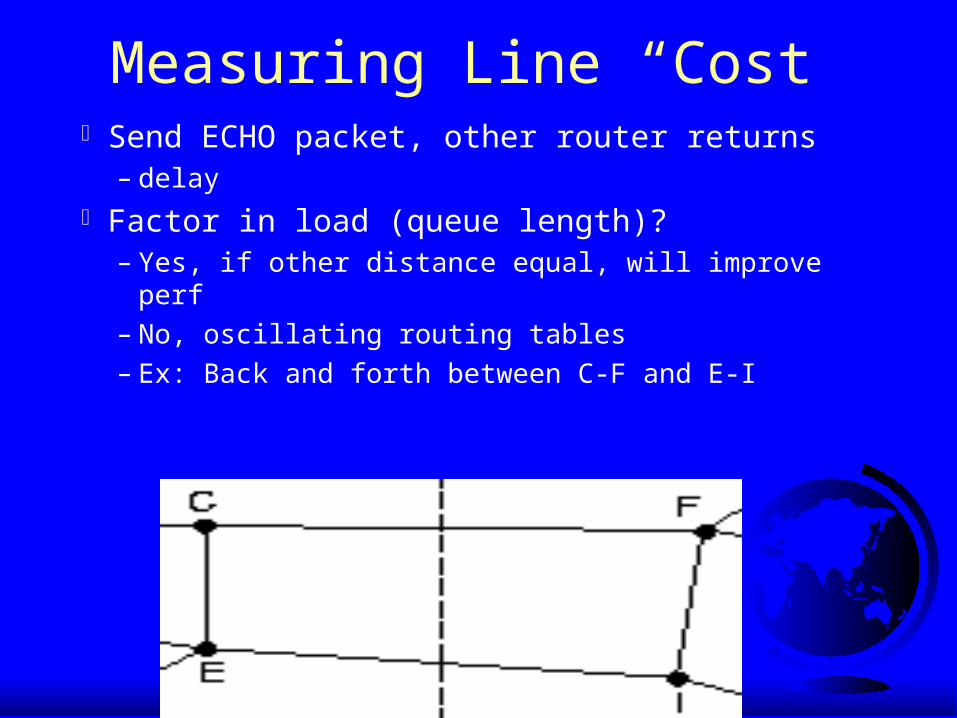
Measuring Line “Cost” Send ECHO packet, other router returns
– delay Factor in load (queue length)?
– Yes, if other distance equal, will improve perf– No, oscillating routing tables– Ex: Back and forth between C-F and E-I

Building Link State Packets Identity of sender, sequence number, age, list of (neighbors +
distance)
When to send them?

Distributing Link State Packets
Tricky if topology changes as packets travel– routes will change “mid-air” based on new topology
Basically, use flooding with checks– increment sequence each time new packet sent
Forward all new packets Discard all duplicates If sequence number lower than max for sending
station– then packet is obsolete and discard

Distribution Problems Sequence numbers wrap around
– use 32 bits and will take 137 years Router crashes … start sequence number at 0?
– next packet it sends will be ignored Corrupted packet (65540)
– packets 5 - 65540 will be ignored Use age field
– decrement every second– if 0, then discard info for that router
Hold for a bit before processing

Keeping Track of Packets
F arrived– ack F– forward A and C
A arrived– ack A– forward C and F
StationB

Keeping Track of Packets
E arrived via EAB and via EFB– send only to C
If C arrives via F before forwarded, updated bits and don’t send to F

Computing New Routes Router has all link state packets
– build subnet graph N routers degree K, O(KN) space Problems
– router lies: forgets link, claims low distance– router fails to forward, or corrupts packets– router runs out of memory, calculates wrong– with large subnets, becomes probable
Limit damage from above when happens

Link State Routing Today
Open Shortest Path First (OSPF) (5.5.5)– used in Internet today
Intermediate Sys Intermediate Sys (IS-IS)– used in Internet backbones– variant used for IPX in Novell networks– carry multiple network layer protocols

A Slight Change in Plans
The Network Layer– Introduction – Routing (5.2) – The Internet (5.5)
ARP (5.5.4) OSPF (5.5.5) BGP (5.5.6)
– Congestion Control (5.3)

Network to Data Link Adress Translation
Internet hosts use IP Data link layer does not understand IP
– Ethernet uses 48-bit address– ex: ifconfig gives 00:10:4B:9E:B3:E6
Q: How do IP addresses get mapped onto data link layer addresses, such as Ethernet?
A: The Address Resolution Protocol (ARP)


Address Resolution Lookup IP of eagle.cs.uni.edu
– DNS (chapter 7)– returns 192.31.65.5
Host 1 builds packet to 192.31.65.5– now, how does data link layer know where to send it?– need Ethernet address of Host 2
Could have config file to map IP to Ethernet– hard to maintain for thousands of machines

Address Resolutioning Host 1 broadcasts packet asking “Who
owns IP address 192.31.65.5?” Each machien checks its IP address. Host 2 responds w/Ethernet address (E2)
– Address Resolution Protocol (ARP) Host 1 data-link can then encapsulate IP
packet in frame addressed to E2 and dump Enet board on Host 2 recognizes, strips
frame header and sends up to IP layer

ARP Optimizations
Send to H2 again?– cache requests (time out in case of new card)
Many times, H1 requires ack from H2– send H1 IP + enet (192.31.65.7, E2)– H2 caches and uses if needed
Hosts broadcast mapping when boot– host looks for its own IP address
should get no answer, else don’t boot
– other enet hosts all can cache answer

Example 2
Host 1 sends message to Host 4
Router does not forward data-link layer broadcasts

Solutions Solution 1
– CS router configured to respond to ARP requests for 192.31.63.0
– Host 1 makes an ARP cache entry of
(192.31.63.8, E3) sends all traffic to Host 4 to CS router
– Called Proxy ARP Solution 2
– Host 1 knows Host 4 is on different subnet sends to CS router
– CS router doesn’t need to know about remote networks

Either way ...
Host 1 packs IP into Enet frame to E3 CS router receives frame, removes packet
– sees 192.31.63.0 to 192.31.60.7 Sends ARP packet onto FDDI
– learns 192.31.60.7 is at F3 Puts packet into payload of FDDI frame and
put on ring EE router receives frame, removes packet ...

Inside Out and Upside Down Can a host learn its IP address at boot?
– Reverse Address Resolution Protocol (RARP) Broadcast:
– “my enet adress 13.05.05.18.01.25”– “does anyone know my IP?”
RARP server sees request, sends IP Allows sharing boot images
– IP not hard-coded RARP broadcasts not across router
– BOOTP uses UDP

Routing on the Internet
Internet made up of Autonomous Systems (AS)
Standard for routing inside AS– interior gateway protocol– OSPF
Standard for routing outside AS– exterior gateway protocol– BGP

Open Shortest Path First (OSPF)
1979, RIP, distance vector, replaced by link-state
In 1990, OSPF standardized “O” is for “Open”, not proprietary ASes can be large, need to scale
– Areas, that are self-contained (not visible from outside)

OSPF, continued Every AS has a backbone, area 0
– all areas connect to backbone, possibly by a tunnel Routers are nodes and links are arcs with weights Computes “shortest” path for each:
– delay– throughput– reliability
Floods link-state packets

ASes, Backbones and Areas

Border Gateway Protocol (BGP)
Inside AS, only efficiency Between AS, have to worry about politics
– No transit traffic through some ASes– Never put Iraq on a route starting at the Pentagon– Do not use the US to get from British Columbia
to Ontario– Traffic starting or ending at IBM should not
transit Microsoft

BGP
Types of networks– stub: only one connection– multiconnected: could transit, but don’t– transit: handle 3rd party, but with restrictions
(backbones) BGP router pairs communicate via TCP
– hides details in between Uses distance vector protocol
– but “cost” can be any metric

BGP
F gets all paths, uses “distance” function for bestCount to infinity fixedRFC 1654

Hierarchical Routing Global picture difficult for large networks Divide into regions
– Router knows detail of its region– Routers in other regions reduced to a point

Reduced Routing Table
•Cost is efficiency
•Consider 1A to 5C•via 3 better for most of 5

Congestion
Losing packetsmakes things
worse

Causes of Congestion Queue build up until full
– Many input lines to one output line– Slow processors– Low-bandwidth lines
system components mismatch (bottleneck)
– Insufficient memory to buffer If condition continues, infinite memory makes
worse!– timeouts cause even more transmission– congestion feeds upon itself until collapse

Flow Control vs. Congestion Control Congestion control (network layer)
– make sure subnet can carry offered traffic– global issues, including hosts and routers
Flow control (data link layer)– point-to-point between sender and receiver– fast sender does not overpower receiver– involves direct feedback to sender by receiver
Ex: Super-computer to PC w/1Gbps line Ex: 1000 computers w/1 Mbps lines
transferring files at 1kbps to other half

Topics
The Network Layer– Introduction – Routing (5.2) – The Internet (5.5, brief)
– Congestion Control (5.3) The Transport Layer

Principles of Congestion Control Control theory: open loop and closed loop Open loop: ahead of time
– solve problem by making sure doesn’t happen– when to accept new traffic– deciding to discard packets and which ones– scheduling decisions within the network
Closed loop: feedback– detect congestion … how?– pass information to system that can adjust

Closed Loop (cont) Metrics to detect congestion:
– percentage of dropped packets– average queue length– number of timed out packets– average packet delay (and std dev of delay)
Transfer info:– router to send packet to traffic source(s)
but this increases the load!
– set bit in acks going back (ECN) Send probe packets out to ask other routers
– ala traffic helicopters to help route cars

Congestion Control Algorithms
Lots of them– taxonomy to view (Yang and Reddy 1995)
Open or Closed (as above) Source or Destination Explicit or Implicit feedback (for closed)
– explicit: send congestion info back to source– implicit: source deduces congestion (by looking
at round-trip time for acks, say)

Congestion Fix Load is greater than resources
– increase resources or decrease load Increase resources
– adding extra leased bandwidth– boost satellite power– split traffic over multiple routes– use backup, fault-tolerant routers– …Difficult under many systems!
Decrease load– at data link, network or transport layer

Preventing Congestion
Traffic is often bursty– periods of lots of traffic– followed by periods of little traffic
If steady rate, easier to avoid congestion Open loop method to help manage
congestion by forcing packets at more predicable rate– Traffic Shaping

Traffic Shaping
Limit rate data is sent User and subnet agree upon certain pattern
(shape) of traffic– especially important for real-time traffic– easier on virtual circuit, but possible on datagram
Monitoring agreement is traffic policing

The Leaky Bucket
No matter how fast water enters bucket, drips out at same rate
If bucket is empty, – then is 0
If bucket is full, then spills over sides– i.e. - lost

The Leaky Bucket Algorithm
Each router has finite internal queue– excess packets discarded
One packet per tick sent– or fixed bytes, if different
sized packets

Leaky Example
200 Mbps network 2 Mbps for long intervals 25 MB/sec for 40 sec
(a) is w/out bucket, (b) is with bucket

Leaky Enhancements
Leaky bucket enforces rigid output rate– instead, allow some speedup of output– token bucket algorithm
Token generated every T seconds– to send packet, station must capture and destroy
Example:

Token Bucket Example
• station wants to send 5 packets
• there are 3 tokens

Traffic Shaping with Token Bucket
Leaky bucket does not allow hosts to “save up” for sending later
Token bucket host can capture up to some max n tokens
Since hosts must stop transmitting when no tokens, then can avoid lost data– leaky bucket will just drop data, resulting in
timeouts and retransmissions (or, just lost data)

Token Bucket Example
250 Kb token bucket Token rate allows 2Mb/sec 25 Mb/sec arrives for 40 sec
– can drain at this rate for about 10 seconds– then must cut back to 2 Mb/sec

Closed-Loop Congestion Control
Router monitors utilization (queue, cpu …)– ex: each line a real number 0.0 to 10.0– how to sample?
f is instantaneous sample (0 or 1) unew = auold + (1-a) f a determines how fast “forgets” old state
– consider a = 0 and a = 1
u above threshold then enters a “warning” state– router sends choke packet to source– original packet is tagged so will not generate more choke packets

Choke Packets (cont) When source receives choke packet, reduces
traffic by X percent– reduce window size or bucket parameters– decrease 0.5, 0.25, … increase slowly, too
Ignore new choke packets from destination for some time interval– why?
Increase flow at some time Variations: degrees of warning

Foul Play Consider A, B and C send through Router Router detects congestion, sends choke packet to each A cuts back packet rate but B and C continue blasting
away– requires voluntary cutback
Transport protocols:– TCP: built in flow-control helps congestion control
– UDP: mis-behaved flows Solution: fair queuing

Fair Queuing
Multiple queues for each output line– one per source
Do round-robin among queues– with n hosts competing, get 1/n of bandwidth
Sending more packets will not help Trouble?
– More bandwidth to hosts with large packets Solution: byte-by-byte round robin
Related Documents