Review Article Software Frameworks for Model Composition Mikel D. Petty, 1 Jungyoon Kim, 2 Salvador E. Barbosa, 1 and Jai-Jeong Pyun 3 1 University of Alabama in Huntsville, Huntsville, USA 2 REALTIMEVISUAL Inc., Seoul, Republic of Korea 3 Agency for Defense Development, Daejeon, Republic of Korea Correspondence should be addressed to Mikel D. Petty; [email protected] Received 10 July 2013; Accepted 17 December 2013; Published 18 February 2014 Academic Editor: Abdelali El Aroudi Copyright © 2014 Mikel D. Petty et al. is is an open access article distributed under the Creative Commons Attribution License, which permits unrestricted use, distribution, and reproduction in any medium, provided the original work is properly cited. A soſtware framework is an architecture or infrastructure intended to enable the integration and interoperation of soſtware components. Specialized types of soſtware frameworks are those specifically intended to support the composition of models or other components within a simulation system. Such frameworks are intended to simplify the process of assembling a complex model or simulation system from simpler component models as well as to promote the reuse of the component models. Several different types of soſtware frameworks for model composition have been designed and implemented; those types include common library, product line architecture, interoperability protocol, object model, formal, and integrative environment. e various framework types have different components, processes for composing models, and intended applications. In this survey the fundamental terms and concepts of soſtware frameworks for model composition are presented, the different types of such frameworks are explained and compared, and important examples of each type are described. 1. Introduction A soſtware framework is an architecture or infrastruc- ture intended to support and enable the integration and interoperation of soſtware components. It may consist of concepts, technologies, tools, protocols, standards, control mechanisms, interfaces, and processes intended to enable the rapid, efficient, and flexible assembly of systems from components in a practical setting. Here we focus our attention on a subclass of soſtware frameworks, specifically those soſtware frameworks where the components are either implementations of models, for example, a model of terrain effect on wheeled vehicle movement, or nonmodel support components, for example, a map display for a user interface, and the framework is intended to support the composition of those models and support components into more complex models and simulation systems. For brevity, such soſtware frameworks specifically designed to support the composition and integration of models and simulation support compo- nents will be referred to as simulation frameworks or when the meaning is clear simply as a framework. is paper’s scope is simulation frameworks for model composition. Its purpose is to review such frameworks, including both their theoretical characteristics and capa- bilities and their implementation and use in practice. To that end, this paper is both a tutorial and a literature survey. As a tutorial, it explains basic context and defines important terminology and provides a categorization scheme for simulation framework types. As a literature survey, it cites and summarizes publications in the research and professional literature. In an important part of the paper’s approach to the subject, several existing soſtware frameworks that have been developed to support model composition are described in some detail. is paper is structured as follows. Section 2 introduces background material, including context and key defini- tions. Section 3 defines categories or types of simulation frameworks. Section 4 describes important examples of the different simulation framework types. Section 5 provides a summary of paper’s findings and recommendations. 2. Background is section introduces essential background information for understanding the soſtware frameworks to be surveyed. It Hindawi Publishing Corporation Modelling and Simulation in Engineering Volume 2014, Article ID 492737, 18 pages http://dx.doi.org/10.1155/2014/492737

Welcome message from author
This document is posted to help you gain knowledge. Please leave a comment to let me know what you think about it! Share it to your friends and learn new things together.
Transcript

Review ArticleSoftware Frameworks for Model Composition
Mikel D. Petty,1 Jungyoon Kim,2 Salvador E. Barbosa,1 and Jai-Jeong Pyun3
1 University of Alabama in Huntsville, Huntsville, USA2 REALTIMEVISUAL Inc., Seoul, Republic of Korea3 Agency for Defense Development, Daejeon, Republic of Korea
Correspondence should be addressed to Mikel D. Petty; [email protected]
Received 10 July 2013; Accepted 17 December 2013; Published 18 February 2014
Academic Editor: Abdelali El Aroudi
Copyright © 2014 Mikel D. Petty et al. This is an open access article distributed under the Creative Commons Attribution License,which permits unrestricted use, distribution, and reproduction in any medium, provided the original work is properly cited.
A software framework is an architecture or infrastructure intended to enable the integration and interoperation of softwarecomponents. Specialized types of software frameworks are those specifically intended to support the composition ofmodels or othercomponents within a simulation system. Such frameworks are intended to simplify the process of assembling a complex model orsimulation system from simpler component models as well as to promote the reuse of the component models. Several differenttypes of software frameworks for model composition have been designed and implemented; those types include common library,product line architecture, interoperability protocol, object model, formal, and integrative environment. The various frameworktypes have different components, processes for composingmodels, and intended applications. In this survey the fundamental termsand concepts of software frameworks for model composition are presented, the different types of such frameworks are explainedand compared, and important examples of each type are described.
1. Introduction
A software framework is an architecture or infrastruc-ture intended to support and enable the integration andinteroperation of software components. It may consist ofconcepts, technologies, tools, protocols, standards, controlmechanisms, interfaces, and processes intended to enablethe rapid, efficient, and flexible assembly of systems fromcomponents in a practical setting. Here we focus ourattention on a subclass of software frameworks, specificallythose software frameworks where the components are eitherimplementations of models, for example, a model of terraineffect on wheeled vehicle movement, or nonmodel supportcomponents, for example, a map display for a user interface,and the framework is intended to support the compositionof those models and support components into more complexmodels and simulation systems. For brevity, such softwareframeworks specifically designed to support the compositionand integration of models and simulation support compo-nents will be referred to as simulation frameworks or whenthe meaning is clear simply as a framework.
This paper’s scope is simulation frameworks for modelcomposition. Its purpose is to review such frameworks,
including both their theoretical characteristics and capa-bilities and their implementation and use in practice. Tothat end, this paper is both a tutorial and a literaturesurvey. As a tutorial, it explains basic context and definesimportant terminology and provides a categorization schemefor simulation framework types. As a literature survey, it citesand summarizes publications in the research and professionalliterature. In an important part of the paper’s approach tothe subject, several existing software frameworks that havebeen developed to support model composition are describedin some detail.
This paper is structured as follows. Section 2 introducesbackground material, including context and key defini-tions. Section 3 defines categories or types of simulationframeworks. Section 4 describes important examples of thedifferent simulation framework types. Section 5 provides asummary of paper’s findings and recommendations.
2. Background
This section introduces essential background information forunderstanding the software frameworks to be surveyed. It
Hindawi Publishing CorporationModelling and Simulation in EngineeringVolume 2014, Article ID 492737, 18 pageshttp://dx.doi.org/10.1155/2014/492737
2 Modelling and Simulation in Engineering
Component52
Component58
Component86
Component87 Framework
Data interfaceData channel
Component38
Component42
Component60
Component99
Component124… Library
Selection
Component52
Component58
Component86
Component87
Component38
Component42
Component60
Component99
Component124· · ·
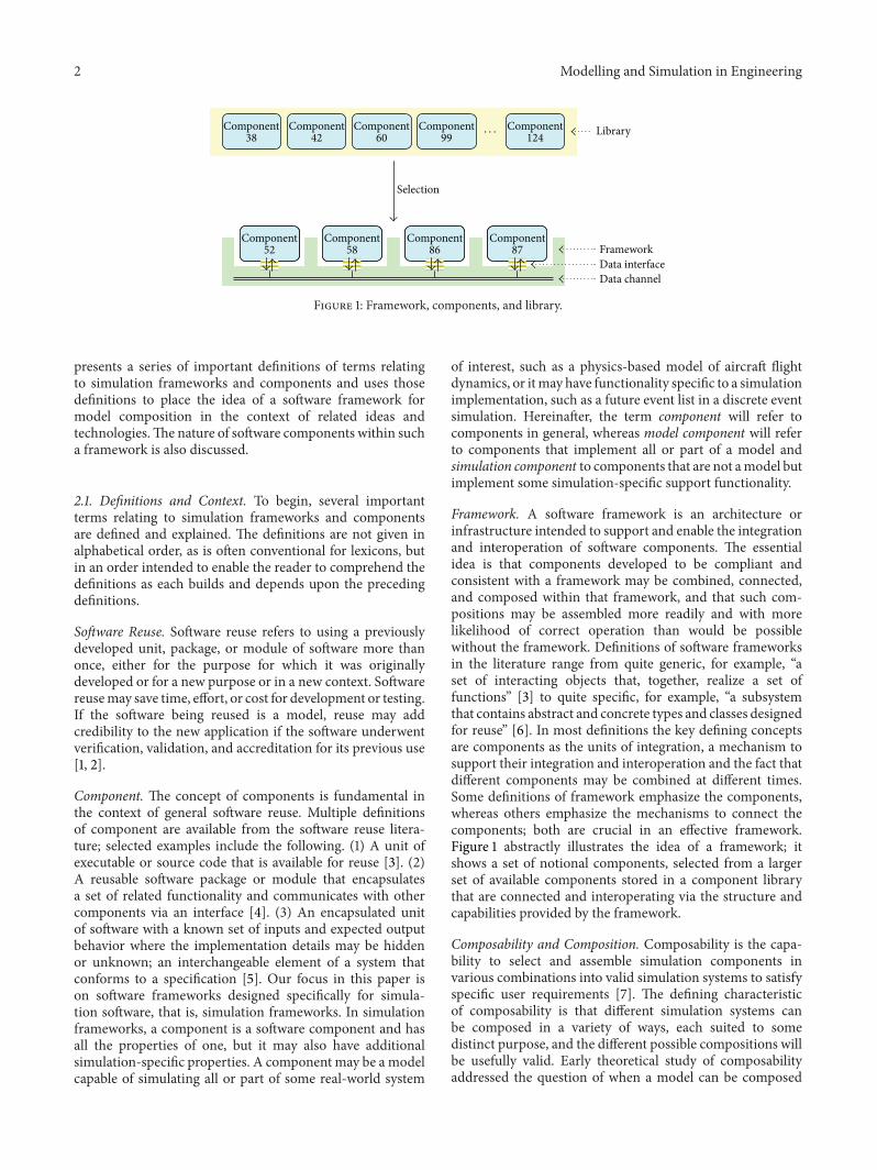
Figure 1: Framework, components, and library.
presents a series of important definitions of terms relatingto simulation frameworks and components and uses thosedefinitions to place the idea of a software framework formodel composition in the context of related ideas andtechnologies.The nature of software components within sucha framework is also discussed.
2.1. Definitions and Context. To begin, several importantterms relating to simulation frameworks and componentsare defined and explained. The definitions are not given inalphabetical order, as is often conventional for lexicons, butin an order intended to enable the reader to comprehend thedefinitions as each builds and depends upon the precedingdefinitions.
Software Reuse. Software reuse refers to using a previouslydeveloped unit, package, or module of software more thanonce, either for the purpose for which it was originallydeveloped or for a new purpose or in a new context. Softwarereusemay save time, effort, or cost for development or testing.If the software being reused is a model, reuse may addcredibility to the new application if the software underwentverification, validation, and accreditation for its previous use[1, 2].
Component. The concept of components is fundamental inthe context of general software reuse. Multiple definitionsof component are available from the software reuse litera-ture; selected examples include the following. (1) A unit ofexecutable or source code that is available for reuse [3]. (2)A reusable software package or module that encapsulatesa set of related functionality and communicates with othercomponents via an interface [4]. (3) An encapsulated unitof software with a known set of inputs and expected outputbehavior where the implementation details may be hiddenor unknown; an interchangeable element of a system thatconforms to a specification [5]. Our focus in this paper ison software frameworks designed specifically for simula-tion software, that is, simulation frameworks. In simulationframeworks, a component is a software component and hasall the properties of one, but it may also have additionalsimulation-specific properties. A component may be a modelcapable of simulating all or part of some real-world system
of interest, such as a physics-based model of aircraft flightdynamics, or itmay have functionality specific to a simulationimplementation, such as a future event list in a discrete eventsimulation. Hereinafter, the term component will refer tocomponents in general, whereas model component will referto components that implement all or part of a model andsimulation component to components that are not amodel butimplement some simulation-specific support functionality.
Framework. A software framework is an architecture orinfrastructure intended to support and enable the integrationand interoperation of software components. The essentialidea is that components developed to be compliant andconsistent with a framework may be combined, connected,and composed within that framework, and that such com-positions may be assembled more readily and with morelikelihood of correct operation than would be possiblewithout the framework. Definitions of software frameworksin the literature range from quite generic, for example, “aset of interacting objects that, together, realize a set offunctions” [3] to quite specific, for example, “a subsystemthat contains abstract and concrete types and classes designedfor reuse” [6]. In most definitions the key defining conceptsare components as the units of integration, a mechanism tosupport their integration and interoperation and the fact thatdifferent components may be combined at different times.Some definitions of framework emphasize the components,whereas others emphasize the mechanisms to connect thecomponents; both are crucial in an effective framework.Figure 1 abstractly illustrates the idea of a framework; itshows a set of notional components, selected from a largerset of available components stored in a component librarythat are connected and interoperating via the structure andcapabilities provided by the framework.
Composability and Composition. Composability is the capa-bility to select and assemble simulation components invarious combinations into valid simulation systems to satisfyspecific user requirements [7]. The defining characteristicof composability is that different simulation systems canbe composed in a variety of ways, each suited to somedistinct purpose, and the different possible compositions willbe usefully valid. Early theoretical study of composabilityaddressed the question of when a model can be composed

Modelling and Simulation in Engineering 3
Composability Reuse
Frameworks Standards
Capabilities
Technologies
Composability
Frameworks
Reuse
Standards
Composable componentsare more likely to be reused
All or part of a framework’sarchitecture may be the
subject of a standard
Com
pone
nts w
ithin
afr
amew
ork
are m
ore
likely
to b
e com
posa
ble
Components within aframework maybereusable in multiplesystems that usethe framework
Componentscompliant with thesame standard are
more likely to becomposable St
anda
rds-
com
plia
ntco
mpo
nent
s are
mor
e lik
ely to
be
reus
able
Figure 2: Survey context.
with other models, and if it is so composed, whether theresulting composition is valid [8, 9]. Similarly, the structuraland numerical inconsistencies that may arise when compos-ing components that implement physics-based models basedon differential equations have been examined [10]. Of moredirect relevance to simulation frameworks, efforts aimed atthe practical implementation of composability have beenidentified [11] (Portions of this paper use concepts and termsintroduced in [11]).
Given this definition of composability, composition (as averb) is the process or capability of selecting and assemblingcomponents for execution. Exactly how the componentsare selected and assembled will depend on the frameworkwithin which they are composed. The details of selectingcomponents dependmore on the framework’s library, and thedetails of assembling them depend more on the framework’simplementation mechanisms. Both will be discussed in thissurvey. Composition (as a noun) refers to a set of componentsthat have been composed to produce an integrated or inter-operable whole (in some situations, phrases such as “set ofcomponents” or “composition of components” will be usedinstead of simply “composition” as a noun. The terms aremeant be synonymous).
Standards. A standard is an agreed-upon convention orrequirement that defines or prescribes some aspect or aspectsof a technical system. Such standards are usually embodied asa formal and configuration-controlled document that spec-ifies consistent engineering or technical criteria, methods,processes or practices. Standards may be considered de jure,which have the formal definition just described, de facto,which exist when a particular product, format, or represen-tation becomes so ubiquitous and dominant that its nonusewould cause significant problems or proprietary, which arestandards-like entities that are owned and controlled by acommercial organization [12]. Simulation standards are thosestandards that apply to simulation, whether to software,development practices, data definitions, or any other aspect ofsimulation.Of special interest in this paper are the distributedsimulation interoperability protocols, including distributedinteractive simulation (DIS) [13], high level architecture(HLA) [14], and test and training enabling architecture
(TENA) [15]), which can be understood as both standardsand frameworks.
Resolution.When describing amodel, resolution is defined as“the degree of detail which with the real world is simulated”[16]. When describing a component, resolution denotes thesize of the component not in bytes or lines of code, but ratherin terms of the scope or extent of the functionality providedby the component. A small component has a narrow andlimited functionality and is likely to be useful only whencombined with other components, for example, a randomnumber generator, whereas a large component may have abroad and extensive functionality and is likely to be capable ofindependent operation even without other components, forexample, semiautomated forces system [17] (Hereinafter, wewill use the terms “small” and “large” to describe componentswith meaning defined here, i.e., scope of the component’sfunctionality, not its size in bytes.). Successful components,that is, those that are reused, may be of any size. Thecomposition of different size components defines differentlevels of composability [7].
Library. In the context of frameworks, a library is a collectionof components that are available for reuse. A library isrealized as a system that accepts, stores, and provides accessto components that may be reused. Issues of configura-tion management (controlling and tracking changes to thecomponents) and discovery (enabling potential users of thecomponents to locate and assess components for reuse) areimportant in software libraries, but are outside the scope ofthis survey. A library may store other artifacts in additionto components, such as metadata, data, or documentation.A range of closely related terms are used, for example,catalog (which specifically stores discovery metadata), reg-istry (which specifically stores metadata schemas), repository(which may contain components developed independentlyand with no prior intent for interoperation), and storehouse(which is generic for storage systems) [1], but the distinctionsbetween these terms will not be needed in this survey.
Equippedwith these definitions, the subject of this surveycan be placed in context, as illustrated in Figure 2. In thefigure “composability” and “reuse” are desired capabilities,

4 Modelling and Simulation in Engineering
and “frameworks” and “standards” are technologies thatcontribute to the achievement of those capabilities. Themechanisms through which technologies and goals supportand enable each other are indicated by the labeled arrows; thedirectionality of the arrows indicates that the “from” technol-ogy or capabilities supports or enables the “to” technology orcapability.
2.2. Characteristics of Components. In simulation frame-works, model components are typically larger than a singlemodel of a domain-specific object but are still small enoughto be confined to a single area of subject matter expertise.Of course, not all components are model components; somemay provide supporting infrastructure to simulation systems,such as a network interface component or an event queuecomponent. Determining the size or functionality of a com-ponent is not amenable to rules applicable in all situations, butthe “satisfies user requirements” clause within the compos-ability definition provides a guideline; a component shouldhave capabilities that are useful to potential users as a unit,neither too small nor too large. The criteria for making thatdetermination will necessarily depend on the application.
The initial development of a composable component isoften more difficult than a noncomposable one, but subse-quent development is made easier by the use of previouslydeveloped components. Contributing to the additional ini-tial effort is the need to document the assumptions andvalidity limits of the models more carefully in a composablecomponent. Modeling practices already considered positivein general, such as using parameters instead of constants,documenting well, checking input for validity limits, andstriving for clarity in implementation, are beneficial in par-ticular to the development of composable components thatembody those models. Not as obvious is that the needs ofcomposability support goodmodeling practices, for example,the requirement imposed by composability to document amodel’s assumptions and limits of validity would help themodeler to consider his/her models more carefully at theoutset.
Components can be integrated and used with other com-ponents only through well-defined interfaces. A componentinterface should define “. . . a set of properties, methods,and events through which external entities can connect toand communicate with the component” [18]. In some casescomponents would have customizable aspects that could bemodified at run-time through the interface.
Structured descriptions or specifications of the compo-nents (sometimes called metadata or metamodels) can beused to guide the processes of selecting components for aspecific purpose and determining if a set of components canbe composed [5]. A component’s specification (metadata)should include details of the component’s interface(s) andmodel(s).
In practice, it is often assumed that anymodel componentthat had been placed in a repository is valid, at least withinbounds stated in its component specification. A component’svalidity constraints are the limits or bounds within with thecomponent’s model is deemed valid and may be defined
at a low level in terms of physical parameter values, timestep sizes, and so on or at a high level in terms of validapplications for the component. Even so, it has been shownthat the validity of individual components does not implythat a composition of them can be assumed to be valid[8]. Validating a composition can use traditional validationmethods, such as comparing composition output data tobaseline data [19] and can also exploit the composition’scomponent structure, such as automatically comparing thedomains of validity for each component with the data theyare receiving from other components in the composition.
3. Framework Types
Several distinct types of software frameworks for modelcomposition have been developed. The mechanisms usedto implement a framework may vary; they include rules,protocols, standards, programming language structures (e.g.,class and type hierarchies), interface definitions and imple-mentations (e.g., application programming interfaces), datatranslators and converters, and data transport utilities. Thesedifferent mechanisms may be used together in a wide rangeof combinations to produce a framework. Moreover, dif-ferent framework types may also vary in the forms andresolutions of the components the framework is designedto connect. Some frameworks are designed for small com-ponents, whereas others are designed for large components.(Here “small” and “large” are used as defined earlier withrespect to resolution.) As a result of this variability inmechanism and design intent, a number of different typesof frameworks have been developed and used within thecommunity of modeling and simulation practitioners. Eachoffers a mechanism for linking components and transportingdata and control between them, and each is intended anddesigned to support components at a certain range of levelsor resolutions but they differ in regarding how to do so.
This section defines six categories or types of softwareframework for model composition and briefly identifiesexamples of each type. (An earlier version of the catego-rization scheme for framework types used here was intro-duced in [11], where the framework types were describedas “approaches to composability engineering”.) Extendeddescriptions of important or interesting example frameworksare given later.
3.1. Common Library. A common library simulation frame-work is based on a collection or set of software modulesor components that are composable or reusable throughconformance to a standard interface or set of interfaces thatallows the modules to interoperate with the other modulesin the library or a subset of them. Typically the componentsin a common library framework are not models that canbe executed in stand-alone mode, although that is not afirm characteristic. The framework may also include tools,services, and standards. Common libraries are developedusing a common set of assumptions underlying the modelswithin them and a common protocol for data transferbetween them. The components are intentionally designedfrom the outset to work together with each other in various
Modelling and Simulation in Engineering 5
combinations. The library may include components withvarying degrees of composability, that is, some of themodulesmay be composable with all or most of the components inthe library, whereas other components may work with only asmall subset of the other components.
Implemented examples of common library simulationframeworks include the Joint Modeling and Simulation Sys-tem (JMASS) [20–23], the Common Simulation Framework(CSF) [24], the Pervasive System for Indoor-GIS (PSI) [25],and J-Sim [26]. It is often the case that a common librarysimulation framework is intended from the outset or evolvesto become focused on a particular category of simulationapplications. JMASS is focused on modeling aircraft avionicsand electronics systems, CSF on modeling tactical missilesystems, PSI onubiquitous computing applications, and J-Simon computer and communications networks. CSF and CSFAwill be described in more detail later.
3.2. Product Line Architecture. A product line architecturesimulation framework is based on the carefully planneddevelopment of multiple related simulation products that,to the extent possible, share common software components.The architecture is realized using two software developmentprocesses. The first is developing a set of components thatwill be integrated in various compositions into the products.The second is integrating subsets of those components intospecific products.The product line architecture includes boththe library of components and an automated (or semiauto-mated) process or tool for integrating them into products[27].The range of possible products is known in advance anddocumented in a detailed specification. The components aredesigned from the outset to work together in those specificproducts. As with a common library framework, typicallynone of the components is a stand-alone simulation product.
Data and control interfaces between the componentswithin an anticipated product are documented in advance inthe specification for each component. The architecture mayprovide a data transfer protocol used within the products.
Examples of simulation products implemented within aproduct line architecture simulation framework include aflight instrumentation trainer [27], a synthetic environmentmodel [28], a physics-based model of weapons effects onbuildings and structures [29], two families of live traininginstrumentation systems [30, 31], and one semiautomatedForces, a real-time constructive combat model [32]. OneSAFwill be described in more detail later.
3.3. Interoperability Protocol. An interoperability protocolsimulation framework is based on the run-time exchangeof simulation data or services, typically using a distributedsimulation interoperability protocol such as ALSP, DIS, HLA,or TENA [33]. In this framework type, simulation systemsconsist of models or support utilities, each of which isan independently executing process or program distributedacross multiple computation platforms that exchange dataduring the execution of a simulation via a network. Thatdata and the transport mechanisms to distribute and deliverit are defined according to the protocol being used. In the
terminology of HLA, which is an architecture standard andinteroperability protocol for such systems, the simulationsare federates and the distributed simulation systems arefederations [14]. The federates can run independently, butnormally interact during execution by sending and receiv-ing data via network messages. In simulation frameworkterms, the federates are the components and the distributedsimulation interoperability protocol is the mechanism forconnecting them. Compliance with such a protocol does not,however, guarantee semantic composability and achieving itmay require considerable additional effort beyond the initialtechnical integration of a system; for example, see [34].
It is useful to distinguish between special-purpose feder-ations, which are developed and used for a single or limitednumber of executions (such as exercises, analyses, or experi-ments) and persistent federations, which are used repeatedlyand possibly modified or enhanced over longer periods oftime. There are numerous examples of interoperability pro-tocol simulation frameworks, that is, persistent federationsdeveloped using a distributed simulation protocol. Examplesinclude the Joint TrainingConfederation [35, 36], theCombatTrauma Patient Simulation (CTPS) [37–39], CombinedArmsTactical Trainer (CATT) [40], the Close Combat TacticalTrainer (CCTT) [40], the Modeling Architecture for Tech-nology, Research, and Experimentation (MATREX) [41, 42],and the Framework for Incident Management (FIM) [43].MATREX will be described in more detail later.
3.4. Object Model. An object model simulation framework isbased on a standard for component specifications; note thatthe standard is for specification, not implementation, of thecomponent. Components that comply with the specificationstandard are intended to be composable with each otherand reusable in a variety of applications. Typically the com-ponents are not themselves stand-alone simulation systems,but rather are meant to be composed with each other inthe context of an overall simulation system. The definingstandard supports interaction of the models with tools andservices via the standardized interfaces and is designed towork with interoperability protocols such as HLA.
The primary implemented example of an object modelsimulation framework is the Base Object Model (BOM)standard [44, 45]. The BOM standard will be described inmore detail later.
3.5. Formal. A formal simulation framework depends upona formal mathematical notation to define the components(usually models), compositions of models, and the interfacesbetween them. The component connection mechanism isprovided by an implementation environment that actuallyprovides the connections specified by the formal definitions.The formal framework type is motivated by a desire tomathematically prove that the components can be composedand to derive their combined behavior once composed.
Examples of formal simulation frameworks include Dis-crete Event System Specification (DEVS) [46] and Model-Based Systems Engineering (MBSE) [47]. The DEVS for-malism supports composability through the use “coupled”

6 Modelling and Simulation in Engineering
(i.e., composite) models that pass data using “ports” (i.e.,interfaces). Model-Based Systems Engineering (MBSE) [47]is another formalism with applicability to simulation. DEVSand MBSE are syntactically quite different but semanticallynearly identical, and they have very similar mathematicalproperties and limits [48, 49]. The DEVS literature is largeand many theoretical studies and example applications areavailable; of particular relevance to simulation frameworksthat use components are [50, 51]. Arguably, the defining char-acteristic of the formal approach, the use of a mathematicalformalism to specify components, can increase the difficultyof using them for large practical applications.
3.6. Integrative Environment. An integrative environmentsimulation framework is a software development and execu-tion environment is used to connect components which mayhave been written with no prior intent to interoperate. Thecomponents may be executable models or data files, and themodel components may be written in different languages ortools, such as Excel and C++. Specialized software wrappersand scripts that are part of the simulation framework areused to connect the components. The integrative environ-ment provides communications channels between them.Theintegrative environment executes the components and relaysthe intercomponent communications along those channels.
Implemented examples of integrative environment sim-ulation frameworks include VisualComposer [52] and Mod-elCenter [53]. VisualComposer is focused on modeling elec-trical systems, whereas ModelCenter is a general purposeframework.ModelCenter is described in more detail later.
4. Example Frameworks
This section describes six important or interesting examplesof simulation frameworks. A framework’s historical signifi-cance, the novelty and effectiveness of its technical features,and its utility in illustrating the comparative strengths andweaknesses of each of the framework types were all consid-ered in choosing the examples. For each example framework,the design intent, capabilities, technical features, and selectedexample applications are explained.
4.1. Common Library Example: Common SimulationFramework. The United States Army Aviation andMissile Research, Development, and Engineering Center(AMRDEC) commissioned the development of the CommonSimulation Framework (CSF) in 1999. The frameworkwas conceived as a standardized structure for dynamicsimulations [24]. Although originally designed to be domainneutral, that is, able to technically support many domains ofdynamic simulations, it rapidly evolved into a toolkit focusedon the modeling and simulation of tactical missile systems[24].
4.1.1. Design Intent. CSF was intended to provide a commonenvironment for simulation and to foster model reuse [24].CSF was envisioned as a framework for the conduct ofdynamic simulations to support systems acquisition and
testing by providing a standard for the management andorganization of object-oriented models that could in turn becomposed into customized simulation systems. The frame-workwas intended to provide a homogenous simulation envi-ronment that would enhance reuse of component models,enable rapid developments, and reduce the learning curveof engineers transitioning between programs. As an object-oriented simulation environment, the primary goal for CSFwas the ability to assemble custom simulation systems bycomposing existing object-oriented models compliant withits specifications.
4.1.2. Capabilities. The allowable resolution of the compo-nent models is variable; the framework only requires that thecomponent interfaces be compliant with CSF’s specifications.The level of detail of any model component’s decompositioninto subcomponents is not constrained by the standard, solong as communications and invocation of services adheredto the framework’s established interfaces. However, theframework’s design encourages model-submodel structuresthat follow the structure of the actual hardware componentsbeing modeled [24]. The system provides a graphical userinterface for assembling composite models. The individualmodels are treated as plug-ins into the overall simulationsystem [54] (A “plug-in” is a software component that addsa feature or capability to an existing software application,to which it connects by a predefined interface. Plug-insrely on the application they connect to and cannot executeindependently.).
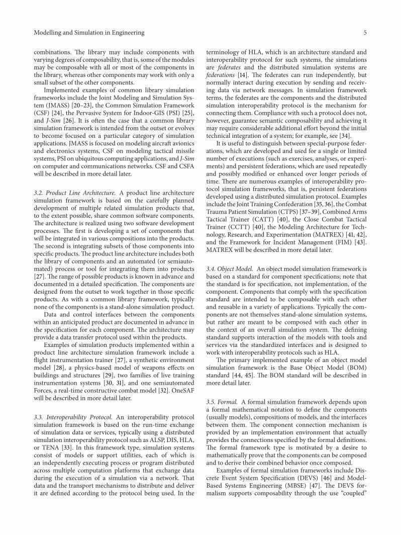
4.1.3. Technical Features. Figure 3(a) depicts the layered CSFarchitecture. As is conventional in layered architectures,software functions in oneCSF layer thatmay invoke functionsin the layer below it. CSF was designed to support variousunderlying hardware platforms and operating systems, suchas Linux, Windows, and IRIX. It supports both discreteevent simulation and differential equations for continuoussystem simulation [55]. CSF is implemented in C++ usinga client-server approach (user interface and models respec-tively). The framework itself is supported by the operatingsystem, programming languages, and a set of general utilities.Compliant models are then constructed to execute based onthe framework. In order to maximize reuse and portability,models are coded using the standard C++ library for server-side frameworks [55]. Once the models are compiled and theframework are linked into a single executable. The modelsexchange data during execution via method calls.
The framework layer provides several features to supportsimulation, including model execution scheduling, file inputand output, numerical integration of physics models, andsimulation dynamics [24]. Both real-time and non-real-timesimulation timing is supported.
4.1.4. Example Applications. TheMissile Component Library(MCLib) is a typical example of aCSF application.MCLibwasdeveloped to promote uniformity and consistency in tacticalmissile simulations by providing a common library to users ofsuch simulations. As a collection of object classes it provides
Modelling and Simulation in Engineering 7
Hardware and firmware
Native operating system (Linux, IRIX)
Common simulation framework
CSF Utilities
Simulation models
Native software support (C ++, , Qt, X)
(a)
Hardware and firmware
Native operating system (Linux, IRIX)
Common simulation framework
Missile-specific models
MCLib
CSF utilities
Native software support (C + +, Qt, X)
(b)
Figure 3: CSF layered architecture (a) and MCLib relationship to CSF and missile models (b); adapted from [56, 57].
general simulation support in two areas: a 6-degrees-of-freedom Propulsion Aerodynamics Controls and Kinematicsmodule (6-PACK) and a Modular Object-Oriented SensorEvaluation Suite (MOSES). The 6-PACK module providesa set of missile kinematic object classes that model theflight and trajectory of simulated missiles. In object-orientedfashion, these classesmay be extended by end users to provideadditional functionality or to modify the default behavior ofthe underlying models. TheMOSES module is a collection ofCSF-native models that capture the behavior of sensors fortarget detection, acquisition, and tracking. As with 6-PACK,MOSES may be tailored or extended in an object-orientedfashion. Architecturally, MCLib is a layer above the CSFframework that provides a library of object classes that maybe invoked for creating individual missile models, withoutremoving the flexibility of direct access to the framework’sfeatures [57]. Figure 3(b) shows the relationship betweenCSF,MCLib, and custom missile-specific models.
A second CSF application extended the framework tosupport hardware-in-the-loop (HWIL) testing [54]. Real-time support features within the framework were extendedto provide constructs necessary to support HWIL operation.To provide a real-time monitoring capability for externalhardware, the frameworkwas enhanced by adding a real-timemonitor class. The monitor class runs as a separate threadto avoid performance degradation in the framework. HWILsupport was demonstrated by driving amotion simulator ratetable with a simulated 6DOF missile trajectory in real-time.
4.1.5. Discussion. CSF’s object-oriented design and simpleuse interface has led to wide use in modeling tactical missilesystems [54], for example, the Non-Line-of-Sight LaunchSystem [56].
4.2. Common Library Example: Composable SimulationFramework Architecture. Within the Korean military theuse of simulation is increasing in parallel with advancesin its defense technologies and weapon systems. In Korea,conventional simulation software development projects haveoften started from scratch; thus, many simulation systemshave been designed with monolithic non-component-basedstructures. The investments in such systems are consideredby some to be inefficient because the resulting systems
frequently have redundant or overlapping capabilities acrossmilitary simulation applications areas such as training, oper-ations research, and combat analysis. In response, the KoreanAgency for Defense Development (ADD) initiated researchtowards composable simulations which are assembled fromreusable software components. The Composable SimulationFramework Architecture (CSFA) is a simulation frameworkpilot project started in 2010 as a feasibility study. CSFA hasa hybrid architecture that could be categorized as either acommon library or an object model framework.
4.2.1. Design Intent. For component composability, semanticconsistency between composed components is a crucialfactor [7]. Therefore, an important design goal of CSFAis to facilitate the reuse of composable components byadopting an overarching reference model that is a structuredrepresentation of the relevant domain knowledge and guidesthe composition of components. Additionally, the referencemodel supports checking the semantic consistency of com-posed components. Components are developed according tothe domain knowledge of the reference model and storedin a repository or common library. Users from variousdomain areas can share common components which are tobe assembled into custom simulation systems for each user’sapplication. CSFA has a layered architecture, which enablesusers to separate domain-specific model components fromdomain-generic simulation engines and supporting tools.Domain-specific model components are layered above thesimulation engine and tool layers, so as to facilitate reusabilityof domain models.
4.2.2. Capabilities. The CSFA framework has two main sec-tions, the reference model and the software. The CSFA ref-erence model, which documents combat domain knowledgeand defines the system’s scope, has two parts, an ontologyand a conceptual model. The reference model’s ontologycontains representations of the combat elements (i.e., entities,units, and systems) corresponding to the likely participantsin the battlefield engagements of interest to ADD. Theontology specifies the capabilities of the individual elements.A portion of the ontology is stored in a database, allowing itto be used to check the consistency of components selectedfor composition with the ontology. The reference model’s

8 Modelling and Simulation in Engineering
Combat model
Army’s SOP, field manual, technical manual, training, and education materials
Applicationsareas
Training
Analysis
Experiment
Simulation engine
Assemble guide
Functions
Actors(entities/
units)
Tasks
(2) Concept model
(3) Component repository(1) Ontology
Army’s task list
Ontology for elements
in battlefield
Assembled components
(Simulation model)
Componentselection
1 and 2 are in a document, “reference model,” while 3 and 4 are software chunks
- btw. units- btw. entities
Primitive entities
Aggregated entities
Passive/environmententities
Function model
Function serviceion ser
Consistency
Scenarioauthoring
Parsing
BOM template
∗POI: pattern of interplay∗∗Composable simulation framework architecture
- Units or entities’ states
(Entities +tasks +functions)
+ supporting tools
(4) CSFA∗∗middleware
∙ POI∗ ∙ State machine
Knowledge, rules Development spec’
...
...
Figure 4: CSFA architecture and context.
conceptual model specifies the possible interactions betweenthe combat elements defined in the ontology. Importantly, asa matter of policy the CSFA reference model can not be easilymodified. Proposed changes to the reference model must bereviewed and approved by an administrative organizationserving as a configuration control board.
The CSFA software likewise has two parts, a componentrepository that stores components that have been developedaccording to the reference model (i.e., the elements in theontology and the interactions in the conceptual model)and middleware that implements the underlying simulationengine as well as supporting tools for functions such asscenario authoring. Figure 4 shows the four parts of CSFAand their context. Brief explanations of each part were asfollows.
(1) Ontology. The ontology expresses military domain knowl-edge, including battlefield elements, is organized hierarchi-cally. It provides semantic content and is CSFA’s most dis-tinctive aspect as compared to other conventional simulationsystems. In the ontology, combat elements are categorizedas physical or abstract; physical elements represent thebattlefield entities such as combatants, automobiles, weapons,rocks, and buildings, whereas abstract elements representbehavioral aspect of elements such as motions, actions, tasks,or missions. The ontology is used to check the consistencybetween assembled components.
(2) Conceptual Model. The conceptual model specifies thebehavioral aspects of the battlefield elements defined in theontology, especially their interactions, and so reflects the pat-tern of interplay between battlefield entities.The specificationtemplate used in the conceptual model is heavily influenced
by the Base Object Model (BOM) SISO standard [44], whichwill be described in some detail later. Each conceptual modelspecification includes both a pattern of interplay and abehavior state machine.The pattern of interplay and the statemachine are expressed as standard UML representations, asequence diagram and a state machine diagram, respectively.The conceptual model is also used to check the consistencyof selected components, and it provides specifications forcomponent development.
(3) Component Repository. The component repository, whichcan be seen as a common library, allows simulation users toselect and compose components.The components implementaspects of the reference model (the ontology and the concep-tual model). Developers produce components according tothe specifications in the reference model.
(4)Middleware.Themiddleware is CSFA’s execution software;it includes the run-time simulation engine and supportingtools. The simulation engine parses the scenario file, loadscomponents and assembles a compositemodel to be executedaccording to the scenario, and executes the assembledmodel.It supports distributed simulation interoperability using thehigh level architecture protocol.Themiddleware’s supportingtools support the various phases of simulation preparation,execution, and analysis; including scenario editing, reposi-tory management, component composition, simulation exe-cution control, 2- and 3-dimensional visualization, and afteraction playback and review.
4.2.3. Technical Features. TheCSFA software is written in theC++ language using the Microsoft Visual Studio integrateddevelopment environment and is implemented as a plug-in.

Modelling and Simulation in Engineering 9
Component explorer: add/modifcation/deletion
of components and elements in ontology
Edit elements of reference model: add/modifcation/deletion
Edit components: component creation/modifcation/deletion
A component cannot be created if the type of the component (the element
reference model) not exists
Figure 5: Example screen image from CSFA’s Component Explorer.
(a) (b)
Figure 6: CSFA screen images, showing entity-level (a) and unit-level (b) combat.
This environment is consistent with ADD’s emphasis on theuse of commercial products. Figure 5 illustrates CSFA’s Com-ponent Explorer, which is part of the component compositionsupporting tool. In the left panel of the figure, the yellowfolders correspond to elements or categories of elements inthe ontology and the black icons are implemented compo-nents. A component cannot be added to the repository unlessthere is a corresponding element in the ontology. Becauseof the policy of limiting ontology modifications mentionedearlier, additions and modifications to the yellow foldersare strictly controlled, thereby preventing the developmentof components that are potentially inconsistent with thereference model.
4.2.4. Example Applications. As this is written, CSFA isan ongoing project; thus, there are no examples of it inpractical application. However, two simulation models havebeen built using CSFA as feasibility demonstrations: direct-fire engagements under different close air support weaponstypes and a large-scale attack of blue infantry battalions onred mechanized battalions. The former models combat at theentity level and the latter at the unit level, demonstratingCSFA’s ability to simulate combat at multiple resolution
levels. Figure 6 shows screen images from both the entity-level model (left) and the unit-level model (right). Theentity-level model includes algorithms which reflect entitylevel engagements such as firing weapons’ kill probabilitiesand targets’ damage assessment. In the unit-level model,Lanchester attrition functions [58] model combat betweenmilitary units, considering factors that include number ofweapons, type of weapons, and unit vulnerability coefficients.
4.2.5. Discussion. The Korean military has already adoptedOneSAF (described later), but it is limited in actual use inKorea because of indigenous Korean tactics, weapons, andenvironments. CSFA is a intended as a means of overcomingthose limitations. To date, CSFA development has achievedonly preliminary component reuse goals, reusing only thecomponents that reflect the elements in the reference modelontology.
Further development is planned to extend the scope ofreuse to nonmodel components that are parts of softwareproducts. An important and advanced feature of CSFA isthe close connection between the system’s “documentation,”that is, the reference model embodied in its ontology and
10 Modelling and Simulation in Engineering
conceptual model, and its “software,” that is, the compo-nent repository and middleware. This connection providessemantic context and consistency to components developedfor the framework, thereby increasing their composability.The usefulness of conceptual models in facilitating modelinteroperability and composability has been observed byothers as well [59].
4.3. Project Line Architecture Example: One SemiautomatedForce. OneSAF is a US Army constructive entity-level com-bat model, designed to simulate brigade and below combatand noncombat operations at the entity level [32]. Devel-opment of OneSAF began in 1996; it has been extendedand enhanced continuously since then. As a semiautomatedforce system, OneSAF generates doctrinally correct tacticalbehaviors up to company-sized forces [17, 30].
4.3.1. Design Intent. OneSAF is intended to be a general-purpose entity-level model that will reduce duplication inthe US Army’s modeling and simulation development efforts,provide improved interoperability and reuse, andmeet futuresimulation needs [60]. Expected uses of OneSAF include thedevelopment of advanced concepts for doctrine and tactics,training of unit commanders and staffs, development ofnew weapon systems, support to test and evaluation, andproduction of data as input to other simulations.
OneSAF is built on a simulation framework known as theOneSAF Product Line Architecture Framework intended to“organize, categorize, and define a layered software structurein order to incrementally meet the OneSAF requirements”[61]. The framework is designed to support various userdomains with multiple applications working from a com-mon architecture and set of components [62]. Within theframework, components, tools, and services can be composedinto products and system compositions specific to userapplications. OneSAF’s product line architecture frameworkhas been widely described [62–66].
4.3.2. Capabilities. The OneSAF Product Line ArchitectureFramework, illustrated in Figure 7, is organized into layersof products and components and employs a hierarchicalcomposition process. Beginning with the component layerin the middle of the figure and moving up, componentsare defined within the framework. Components may be oneof four types: model, tool, infrastructure, and repository[62]. The framework allows independent development ofcomponents; they must have complete service and interfacedefinitions and formal documentation. A single componentmay be used in multiple products and system compositions;conversely, multiple implementations of a single componentare possible for situations when a specific product requiresa particular variation of a component. One or more compo-nents are composed into products, shown in the figure in theproduct layer. Each product is a distinct unit of simulationor simulation-support functionality. Finally, products arecomposed into system configurations, shown in the figure inthe system compositions layer, which are complete executablesystems that provide configured end-user functionality for
operational use within mission areas, such as analysis ortraining. Examples of typical system compositions a singleplatform standalone executable to be used for force structureanalysis or a multiplatform federated executable to be usedfor distributed staff training [61].
The layers below the component layer figure containcomponents that provide capabilities that will be used bymost or all products or that enable the composition process.The component support layer provides common simulationand composition services that are used by components orused to compose components. The repository componentlayer is a set of repositories for storing compositions and sim-ulation data.The common services layer provides shared andnon-domain-specific services, such as databasemanagement,time synchronization, and interoperability protocol services.Finally, the platform layer abstracts the hardware and soft-ware environment in which the components, products, andsystem compositions operate.
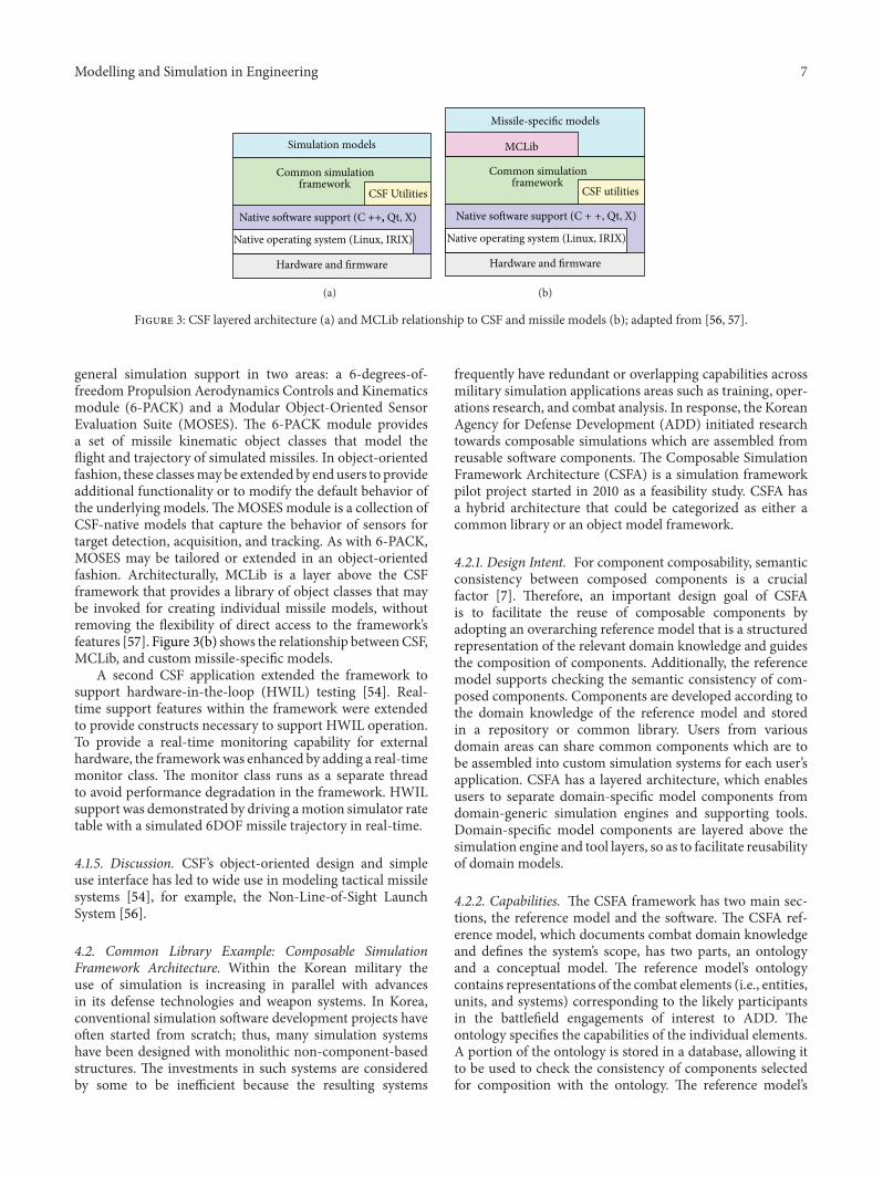
4.3.3. Technical Features. The components can be assembledwithin the framework into twelve specific products thatcollectively make up the OneSAF product line [30, 62]:
(1) System composer composes components into prod-ucts and products into system compositions.
(2) Knowledge engineering environment stores and orga-nizes combat domain knowledge.
(3) Event planner plans activities and tasks in preparationfor a simulation event or exercise.
(4) Model composer composes primitive models, suchas physical or behavioral models, into compositemodels.
(5) Simulation generator selects terrain and scenarioinformation for an execution.
(6) Technical manager supports execution configuration,performance prediction, and benchmarking.
(7) Simulation core serves as the runtime engine for asimulation execution.
(8) Simulation controller provides mechanisms, such asmaps, overlays, and monitors for run-time control ofa simulation execution.
(9) C4I adapter connects OneSAF system compositionsand actual command, control, communications, com-puters, and intelligence (C4I) devices.
(10) Analysis and review provides recording, playback, andanalysis of simulation execution data.
(11) Repository manager enables creation and use of localand remote components and data.
(12) Maintenance environment provides an integrated soft-ware development environment.
4.3.4. Example Applications. OneSAF has been used for anextensive range of analysis, acquisition, and training appli-cations. In addition to everyday applications, some unusualexamples include the creation of a tool providing course of

Modelling and Simulation in Engineering 11
Managementand control
tool
Component support layer
Product layer
System composition layer
Repository component layer
Environment
Common services layer
Platform layer
Environmentdatabase
generationenvironment
Militaryscenario
developmentenvironment Entity
composer
KA/KEtools
Behaviorcomposer
Unitcomposer
Systemcomposer
tool
Icontool
Battlefieldenumeration
tool
Environmentcomposer
Datacollection
specificationtool
Simulationconfiguration
and assetmanagement
toolFederation
developmenttool
Performancemodeling
toolNetwork
loadertool
Benchmarktool
Entitymodels
Behaviormodels
Unitmodels
Environmentmodels
Physicalmodels
Managementand control
tool
Stealthtool
Systemconfiguration
and assetmanagement
tool
Monitorand control
servicesTranslation
servicesConnectservices
Afteractionreview
Annotatortool
Modelverification
tool
Datamanagement
toolInformationmeta-data
tool
Softwareengineeringenvironment
Configurationmanagement
toolDefect
toolSoftware
verificationtool
Systemaccount
toolSoftware
installtool
Systemdistribution
tool
Component layer
Compositionservices
Plan viewdisplay
Environmentruntimeservices
Environmentreasoningservices
Graphicaluser interface
services
Datacollectionservices
Simulationservices
Simulationobject runtime
databaseModelingservices
Simulationrepository
services
Systemcomposer
Knowledgeengineeringenvironment
Eventplanner
Modelcomposer
Simulationgenerator
Technicalmanager
Simulationcore
Simulationcontroller
C4Iadaptor
Analysisand review
Repositorymanager
Maintenanceenvironment
Leader and stafftraining
Seamlesstraining
Force andorganizations analysis
Test andevaluation
KA/KErepository
Militaryscenario
repositoryEnvironment
repositorySoftware
repositorySystem
compositionrepository
Local exerciseenvironment
repository
Parametricand initialization
repository
Simulationoutput
repository
Monitorservices
Coordinateservices
Timeservices
Namedirectoryservices
Messagingservices
Interchangeservices
Middlewareservices
HardwareOperating
systemNetwork
· · ·
Figure 7: The OneSAF product line architecture framework; adapted from [30].
action analysis andmission rehearsal capabilities [67], testingalgorithms for real C4I systems [68], modeling World WarII tank combat [69], creation of a “cyber range” for cyberwarfare analysis and training [70], and virtual training onoperating construction equipment [71].
4.3.5. Discussion. The product line architecture approachuses layers of components and products to develop specificsimulation systems. Advantages of this type of simulationframework are that only the components needed for aspecific user application are composed, reducing compu-tational requirements; components can be replaced, easing
maintenance and upgrades; and development of new modelsand tools is encouraged by the ability to reuse existingcomponents as context [61]. However, in the framework theproducts and system compositions are normally defined inadvance, and OneSAF has no inherent mechanism to enforcethe assumptions and dependencies of a component if it isreused in a different context [72]. Ultimately, the developeris responsible for ensuring that a composed product is valid.
4.4. Interoperability Protocol Example: Modeling Architecturefor Technology, Research, andExperimentation. Development

12 Modelling and Simulation in Engineering
began of the US Army’s Modeling Architecture for Technol-ogy, Research, and Experimentation (MATREX) in 2006 [41].MATREX consists of a large set of distinct combat-relatedmodels and simulation tools interoperable via HLA or TENA[42] and is an example of how an interoperability protocolmay serve as a simulation framework. (The terminologyof HLA and TENA differ slightly; in this description ofMATREX HLA terms are used.)
4.4.1. Design Intent. MATREX is intended to support theintegration of live, virtual, and constructivemodels operatingat either the entity or engineering level [41]. From an HLAperspective, MATREX is a persistent federation, that is,an HLA federation that after initial development is reusedrepeatedly, perhaps with modifications and enhancements,over a long period of time. Like many persistent federations,MATREX is not specific to any particular application; rather,it is intended to be adaptable to a range of applications as isor through extension.
4.4.2. Capabilities. The MATREX federation includesapproximately 30 different simulation applications orfederates. One important MATREX federate is OneSAF(described earlier), which provides broad capabilities tosimulate a range of combat entity types and interactions.Also more specialized federates that model specific typesof entities, interactions, and phenomena in more detail toprovide for higher-fidelity or higher-resolution simulationas needed are present. Among them are the AviationMobility Server, the Countermine Server, the MissileServer, the Weather Server, the Vehicle Dynamics MobilityServer, the Chemical Biological Simulation Suite [73], theComprehensive Munitions and Sensor Simulation, theLogistics Server, and the Vehicle Level Human PerformanceModel. Five MATREX federates, collectively known as theC3 Grid, provide services related to modeling command,control, and communications actions and effects. In additionto federates that provide modeling capabilities, MATREXincludes a set of nonmodel tools that support testing anddebugging, execution control, and results logging andanalysis.
4.4.3. Technical Features. The MATREX architecture isbroadly organized into three layers [41]. The first layerincludes the federates themselves, which may include high-fidelity physics-based engineering models of battlefield vehi-cles, sensors, weapons, and so on, as well as tools to supportsystem integration, testing, and analysis. The second layeris the core architecture, which includes the HLA interface,the object model used by the MATREX federations, and asoftware middleware layer, which stands between the inter-operability protocols and the federates’ model-specific code.The third layer is the distributed execution infrastructure,with includes a secure network that links MATREX federatesat distributed sites. The MATREX middleware is commonacross the federates; they communicate through it at run-time. It includes an application programming interface and
code-generated software that abstracts the details of theinteroperability protocol and the object model [74].
The MATREX Federation Object Model (FOM) wasinitially based on the Real-time Platform Reference FOM,an HLA FOM that specifies as closely as possible the sameentities, attributes, interactions, and parameters defined intheDIS protocol [75].TheMATREX FOMhas been extendedwith objects and interactions of special interest to theMATREX user community.
4.4.4. Example Applications. MATREX applications haveincluded integration of human behavior models into theMATREX architecture [76], support of distributed test eventsfor network centric warfare systems [77], and networkedeffects command and control [41].
4.4.5. Discussion. An important feature of the MATREXframework is its middleware, which provides an interfacebetween the federates and the interoperability protocol beingused to connect them. The middleware is intended to reduceor eliminate the need to modify the federates in the eventof changes to the interoperability protocol and its supportsoftware, for example, different versions of the RTI, as wellas differences between object models. The MATREX versionof the HLA RTI has a variety of parameters that allowusers to configure HLA services, such as Data DistributionManagement, as best suits their application [78]; properconfiguration of the MATREX RTI for Data DistributionManagement requires some care [79].
4.5. Object Model Example: Base Object Models. The BaseObject Model (BOM) specification (the description of BaseObject Models given here is adapted from portions of[45]), which was standardized by Simulation InteroperabilityStandards Organization (SISO) in 2006, is intended to enablemodel developers and simulation engineers to createmodularand composable conceptual models and object models whichcan be used in the design or specification of executablesimulations or simulation environments [44].
4.5.1. Design Intent. The BOM standard is meant to providea standardized means to represent important aspects of aconceptual model. Conceptual models in general are notexecutable; rather they are normally developed as a precursorto the subsequent development of an executable model[19, 80]. Conceptual models are used to document andcommunicate “what is to be represented (in the executablemodel), the assumptions limiting those representations, andother capabilities needed to satisfy user’s requirements” [81].
A BOM model (The term Base Object Model and theacronym BOM are used in the literature to refer to both thestandard and to a particular instance of a conceptualmodel orobject model developed according to the standard. To reducethe potential for confusion, in this paper we will used thephrase “BOM model” for the latter meaning, even thoughthat phrase is technically redundant in that the “M” in BOMstands for “model”.) is intended to be a “reusable package of
Modelling and Simulation in Engineering 13
Assign control of interceptor
Direct interceptor to target
Engage target
Air operations center Air mission control function Interceptor Target
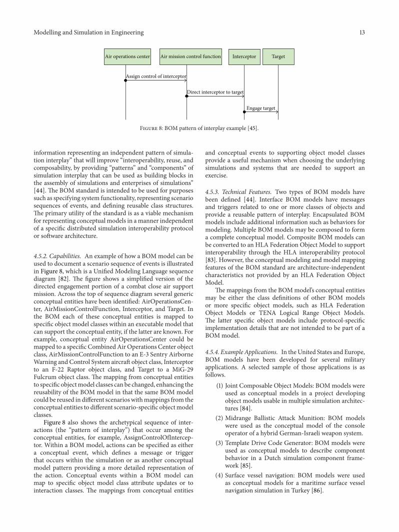
Figure 8: BOM pattern of interplay example [45].
information representing an independent pattern of simula-tion interplay” that will improve “interoperability, reuse, andcomposability, by providing “patterns” and “components” ofsimulation interplay that can be used as building blocks inthe assembly of simulations and enterprises of simulations”[44]. The BOM standard is intended to be used for purposessuch as specifying system functionality, representing scenariosequences of events, and defining reusable class structures.The primary utility of the standard is as a viable mechanismfor representing conceptual models in amanner independentof a specific distributed simulation interoperability protocolor software architecture.
4.5.2. Capabilities. An example of how a BOMmodel can beused to document a scenario sequence of events is illustratedin Figure 8, which is a Unified Modeling Language sequencediagram [82]. The figure shows a simplified version of thedirected engagement portion of a combat close air supportmission. Across the top of sequence diagram several genericconceptual entities have been identified: AirOperationsCen-ter, AirMissionControlFunction, Interceptor, and Target. Inthe BOM each of these conceptual entities is mapped tospecific object model classes within an executable model thatcan support the conceptual entity, if the latter are known. Forexample, conceptual entity AirOperationsCenter could bemapped to a specific CombinedAir Operations Center objectclass, AirMissionControlFunction to an E-3 Sentry AirborneWarning and Control System aircraft object class, Interceptorto an F-22 Raptor object class, and Target to a MiG-29Fulcrum object class. The mapping from conceptual entitiesto specific objectmodel classes can be changed, enhancing thereusability of the BOM model in that the same BOM modelcould be reused in different scenarioswithmappings from theconceptual entities to different scenario-specific objectmodelclasses.
Figure 8 also shows the archetypical sequence of inter-actions (the “pattern of interplay”) that occur among theconceptual entities, for example, AssignControlOfIntercep-tor. Within a BOM model, actions can be specified as eithera conceptual event, which defines a message or triggerthat occurs within the simulation or as another conceptualmodel pattern providing a more detailed representation ofthe action. Conceptual events within a BOM model canmap to specific object model class attribute updates or tointeraction classes. The mappings from conceptual entities
and conceptual events to supporting object model classesprovide a useful mechanism when choosing the underlyingsimulations and systems that are needed to support anexercise.
4.5.3. Technical Features. Two types of BOM models havebeen defined [44]. Interface BOM models have messagesand triggers related to one or more classes of objects andprovide a reusable pattern of interplay. Encapsulated BOMmodels include additional information such as behaviors formodeling. Multiple BOM models may be composed to forma complete conceptual model. Composite BOM models canbe converted to an HLA Federation Object Model to supportinteroperability through the HLA interoperability protocol[83]. However, the conceptual modeling and model mappingfeatures of the BOM standard are architecture-independentcharacteristics not provided by an HLA Federation ObjectModel.
The mappings from the BOMmodel’s conceptual entitiesmay be either the class definitions of other BOM modelsor more specific object models, such as HLA FederationObject Models or TENA Logical Range Object Models.The latter specific object models include protocol-specificimplementation details that are not intended to be part of aBOMmodel.
4.5.4. Example Applications. In theUnited States and Europe,BOM models have been developed for several militaryapplications. A selected sample of those applications is asfollows.
(1) Joint Composable Object Models: BOMmodels wereused as conceptual models in a project developingobject models usable in multiple simulation architec-tures [84].
(2) Midrange Ballistic Attack Munition: BOM modelswere used as the conceptual model of the consoleoperator of a hybrid German-Israeli weapon system.
(3) Template Drive Code Generator: BOM models wereused as conceptual models to describe componentbehavior in a Dutch simulation component frame-work [85].
(4) Surface vessel navigation: BOM models were usedas conceptual models for a maritime surface vesselnavigation simulation in Turkey [86].
14 Modelling and Simulation in Engineering
(5) Torpedo engineering: BOM models were used asconceptual models for reusable components imple-menting underwater acoustic models [87].
(6) Airborne Electronic Attack: BOM models developedfromUSDepartment of Defense Architecture Frame-work (DoDAF) viewswere used as conceptualmodelsfor the airborne electronic attack architecture for theUS Air Force [88].
(7) Human behavior modeling: BOM models have beenproposed as a standard mechanism for encodingand documenting multiresolution human behaviormodels [89].
4.5.5. Discussion. It is not clear that the BOM standard fullyqualifies as a simulation framework as defined earlier. TheBOM standard is for component specifications (componentmodels and object models), not components, and it does notprovide an explicit integral mechanism for linking compo-nents developed according to the standard. Instead, the BOMstandard assumes that some other framework, usually one ofthe distributed simulation interoperability protocols such asHLA or TENA, will serve to link the components that aredeveloped to the BOM standard.
BOM models are intended to supplement the semanticinformation present in an interoperability protocol objectmodel, but mappings from BOM models to ontologieshave been proposed to provide additional semantic contentbeyond that in the BOMmodels themselves [90].
4.6. Integrative Environment Example: ModelCenter. Model-Center (ModelCenter is a commercial product of PhoenixIntegration.) is a graphical toolkit and software frameworkfor engineering design integration and optimization. Itallows exploration of the design space to identify promisingapproaches to the problem under analysis.
4.6.1. Design Intent. ModelCenter is intended to facilitate theintegration of multiple distinct models used in the processof engineering design. It supports the creation of linkedapplications by enabling the automatic runtime exchange ofdata between the differentmodels.ModelCenterwas designedto provide ease of use, in the form of integration with existinganalysis and modeling packages allowing direct reuse ofexisting models, improved engineering design, via supportfor early identification of design problems and analysis of thetrade space, and error reduction, by automating the processof creating data exchange channels between models [53].
4.6.2. Capabilities. ModelCenter’s capabilities fall into threeprimary areas [53, 91].
(1) Model Wrapping. To link the multiple models that makeup the composite model, automated data exchange channelsare created by “wrapping” the component models. Threedifferent types of wrapper support various forms of data. Filewrapping wraps existing data files through the creation ofinput and output files for the various components and stages
of the model by identifying which items in a file serve asinput to each model, and what each model must output foruse by subsequent stages. Script wrapping is accomplishedvia the ModelCenter application programming interfaces tohandle formats such as theMicrosoft COM protocol. Customwrapping is available through tailored applications writtenin high-level languages such as C++ or Java. This method isemployed when third party models provide APIs that allowaccess to internal functions.
(2) Visual Model/Process Integration. The graphical interfaceallows the construction of designs, through the linking ofapplications and models, and the execution of simulations.Linking is accomplished via drag-and-drop interfaces andsupport not only direct connections but also conditionaland looping associations between models. Execution of anddataflow between linked components are supported directlyfor models such as Excel, MATLAB, or common computer-aided design and computer-aided engineering tools, as welladditional custom model types. Other components mayrequire scripting or user intervention for execution.
(3) Analysis and Optimization. Once integrated, the com-posite model may be executed repeatedly for trade spaceexploration or design optimization. ModelCenter is able toprocess both discrete and continuous variables with the goalof minimizing, maximizing, or solving for given attributes,while satisfying specified constraints.
4.6.3. Technical Features. Model wrapping is available viaboth a separate tool and a native component ofModelCenter.The latter provides the ability to wrap ASCII files via a point-and-click interface that identifies variables within the files.For files that have a defined structure, such as FORTRANname lists and name-value pairs, matching patterns may becreated to automate thewrapping process. Additionally, it willprocess files from commercial computer-aided engineeringproducts. Scripting capability and functions are also available.
Along with the previously mentioned drag-and-dropcapability and simulation control functions, the graphicalinterface provides a robust set of logical connectors, includingif-then, switches, parallel branches, and looping, which canbe used to link component models. Characterization of thetype of data exchange across the links (values, arrays, files, orobjects) is also possible.
ModelCenter can generate and analyze response surfaces.The data composing the surface may come from previoussimulation runs or may be approximations created withinthe toolkit. The process supports curve fit types such asthe polynomial or Kringing methods. The resulting responsesurface may then be incorporated into the set of linkedmodels. Response surfaces created by simulations may beincorporated in lieu of the simulation.
AnotherModelCenter component performs optimizationof variables in the design. The optimizer employs geneticalgorithms and recommends algorithmic approaches andvariable selection from questions posed to engineers aboutthe design and its goals. Final results are provided viaoptimization reports. A software development kit that allows
Modelling and Simulation in Engineering 15
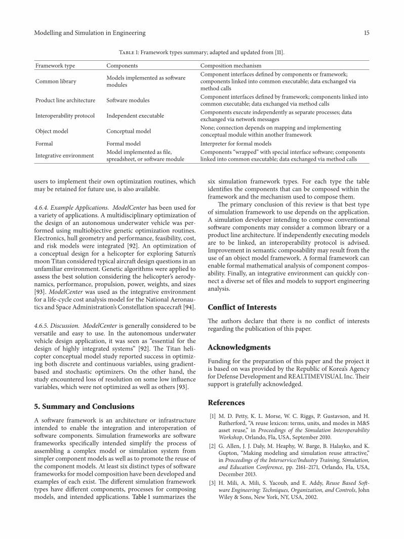
Table 1: Framework types summary; adapted and updated from [11].
Framework type Components Composition mechanism
Common library Models implemented as softwaremodules
Component interfaces defined by components or framework;components linked into common executable; data exchanged viamethod calls
Product line architecture Software modules Component interfaces defined by framework; components linked intocommon executable; data exchanged via method calls
Interoperability protocol Independent executable Components execute independently as separate processes; dataexchanged via network messages
Object model Conceptual model None; connection depends on mapping and implementingconceptual module within another framework
Formal Formal model Interpreter for formal models
Integrative environment Model implemented as file,spreadsheet, or software module
Components “wrapped” with special interface software; componentslinked into common executable; data exchanged via method calls
users to implement their own optimization routines, whichmay be retained for future use, is also available.
4.6.4. Example Applications. ModelCenter has been used fora variety of applications. A multidisciplinary optimization ofthe design of an autonomous underwater vehicle was per-formed using multiobjective genetic optimization routines.Electronics, hull geometry and performance, feasibility, cost,and risk models were integrated [92]. An optimization ofa conceptual design for a helicopter for exploring Saturn’smoon Titan considered typical aircraft design questions in anunfamiliar environment. Genetic algorithms were applied toassess the best solution considering the helicopter’s aerody-namics, performance, propulsion, power, weights, and sizes[93]. ModelCenter was used as the integrative environmentfor a life-cycle cost analysis model for the National Aeronau-tics and Space Administration’s Constellation spacecraft [94].
4.6.5. Discussion. ModelCenter is generally considered to beversatile and easy to use. In the autonomous underwatervehicle design application, it was seen as “essential for thedesign of highly integrated systems” [92]. The Titan heli-copter conceptual model study reported success in optimiz-ing both discrete and continuous variables, using gradient-based and stochastic optimizers. On the other hand, thestudy encountered loss of resolution on some low influencevariables, which were not optimized as well as others [93].
5. Summary and Conclusions
A software framework is an architecture or infrastructureintended to enable the integration and interoperation ofsoftware components. Simulation frameworks are softwareframeworks specifically intended simplify the process ofassembling a complex model or simulation system fromsimpler component models as well as to promote the reuse ofthe component models. At least six distinct types of softwareframeworks for model composition have been developed andexamples of each exist. The different simulation frameworktypes have different components, processes for composingmodels, and intended applications. Table 1 summarizes the
six simulation framework types. For each type the tableidentifies the components that can be composed within theframework and the mechanism used to compose them.
The primary conclusion of this review is that best typeof simulation framework to use depends on the application.A simulation developer intending to compose conventionalsoftware components may consider a common library or aproduct line architecture. If independently executing modelsare to be linked, an interoperability protocol is advised.Improvement in semantic composability may result from theuse of an object model framework. A formal framework canenable formal mathematical analysis of component compos-ability. Finally, an integrative environment can quickly con-nect a diverse set of files and models to support engineeringanalysis.
Conflict of Interests
The authors declare that there is no conflict of interestsregarding the publication of this paper.
Acknowledgments
Funding for the preparation of this paper and the project itis based on was provided by the Republic of Korea’s Agencyfor Defense Development and REALTIMEVISUAL Inc.Theirsupport is gratefully acknowledged.
References
[1] M. D. Petty, K. L. Morse, W. C. Riggs, P. Gustavson, and H.Rutherford, “A reuse lexicon: terms, units, and modes in M&Sasset reuse,” in Proceedings of the Simulation InteroperabilityWorkshop, Orlando, Fla, USA, September 2010.
[2] G. Allen, J. J. Daly, M. Heaphy, W. Barge, B. Halayko, and K.Gupton, “Making modeling and simulation reuse attractive,”in Proceedings of the Interservice/Industry Training, Simulation,and Education Conference, pp. 2161–2171, Orlando, Fla, USA,December 2013.
[3] H. Mili, A. Mili, S. Yacoub, and E. Addy, Reuse Based Soft-ware Engineering: Techniques, Organization, and Controls, JohnWiley & Sons, New York, NY, USA, 2002.

16 Modelling and Simulation in Engineering
[4] Y. Yu, T. Li, Q. Liu, and F. Dai, “Approach to modelingcomponents in software architecture,” Journal of Software, vol.6, no. 11, pp. 2196–2200, 2011.
[5] K. L. Morse, M. D. Petty, P. F. Reynolds, W. F. Waite, and P.M. Zimmerman, “Findings and recommendations from the2003 composable mission space environments workshop,” inProceedings of the Simulation InteroperabilityWorkshop, pp. 313–323, Arlington, Va, USA, April 2004.
[6] I. Jacobson, M. Griss, and P. Jonsson, Software Reuse: Archi-tecture, Process, and Organization for Success, ACM Press, NewYork, NY, USA, 1997.
[7] M. D. Petty and E. W. Weisel, “A composability lexicon,” inProceedings of the Simulation InteroperabilityWorkshop, pp. 181–187, Orlando, Fla, USA, March-April 2003.
[8] E. W. Weisel, R. R. Mielke, and M. D. Petty, “Validity ofmodels and classes of models in semantic composability,” inProceedings of the Simulation Interoperability Workshop, pp.526–536, Orlando, Fla, USA, September 2003.
[9] M. D. Petty, E. W. Weisel, and R. R. Mielke, “Composabilitytheory overview and update,” in Proceedings of the SimulationInteroperability Workshop, pp. 431–437, San Diego, Calif, USA,April 2005.
[10] P. Bunus and P. Fritzson, “Automated static analysis of equation-based components,” Simulation, vol. 80, no. 7-8, pp. 321–345,2004.
[11] E. W. Weisel, M. D. Petty, and R. R. Mielke, “A survey ofengineering approaches to composability,” in Proceedings of theSimulation Interoperability Workshop, pp. 722–731, Arlington,Va, USA, April 2004.
[12] A. E. Henninger, K. L. Morse, M. L. Loper, and R. D. Gibson,“Developing a process for M&S standards management withinDoD,” in Proceedings of the Interservice/Industry Training,Simulation, and Education Conference, Orlando, Fla, USA,November-December 2009.
[13] R. C. Hofer and M. L. Loper, “DIS today,” Proceedings of theIEEE, vol. 83, no. 8, pp. 1124–1137, 1995.
[14] J. S. Dahmann, F. Kuhl, and R. Weatherly, “Standards forsimulation: as simple as possible but not simpler the high levelarchitecture for simulation,” SIMULATION, vol. 71, no. 6, pp.378–387, 1998.
[15] E. T. Powell and J. R. Noseworthy, “The test and trainingenabling architecture,” in Engineering Principles of CombatModeling and Distributed Simulation, A. Tolk, Ed., pp. 449–477,John Wiley & Sons, Hoboken, NJ, USA, 2012.
[16] C. M. Banks, “Introduction to modeling and simulation,” inModeling and Simulation Fundamentals: Theoretical Underpin-nings and Practical Domains, J. A. Sokolowski and C. M. Banks,Eds., pp. 1–24, John Wiley & Sons, Hoboken, NJ, USA, 2010.
[17] M. D. Petty, “Behavior generation in semi-automated forces,”in The PSI Handbook of Virtual Environment Training andEducation: Developments for the Military and Beyond, Volume2: VE Components and Training Technologies, D. Nicholson, D.Schmorrow, and J. Cohn, Eds., pp. 189–204, Praeger SecurityInternational, Westport, Conn, USA, 2009.
[18] D. Krieger and R. M. Adler, “The emergence of distributedcomponent platforms,” Computer, vol. 31, no. 3, pp. 43–53, 1998.
[19] M. D. Petty, “Verification, validation, and accreditation,” inModeling and Simulation Fundamental: Theoretical Underpin-nings and Practical Domains, J. A. Sokolowski and C. M. Banks,Eds., pp. 325–372, JohnWiley & Sons, Hoboken, NJ, USA, 2010.
[20] D. Russell andW.McQuay, “The joint modeling and simulationsystem: a common modeling architecture for the DoD,” inProceedings of the Winter Simulation Conference (WSC ’93), pp.984–988, Los Angeles, Calif, USA, December 1993.
[21] V. K. Handley, P. M. Shea, and M. Morano, “An introductionto the Joint Modeling and Simulation System (JMASS),” in Pro-ceedings of the Simulation Interoperability Workshop, Orlando,Fla, USA, September 2000.
[22] B. McCauley, J. Hill, P. Gravitz, and D.McFarland, “JMASS98—engagement level simulation framework++,” in Proceedings ofthe Simulation Interoperability Workshop, Orlando, Fla, USA,March 2000.
[23] R. J. Meyer, “Joint Modeling and Simulation System (JMASS):what it does, . . . and what it doesn’t!,” in Proceedings ofthe Simulation Interoperability Workshop, Orlando, Fla, USA,March 2001.
[24] B. Haynes, T. Carroll, D. Tollison, W. Kendrick, and A. Salter,“Development of the Missile Component Simulation Library(MCLib) for tactical missile simulation,” in Proceedings ofthe Huntsville Simulation Conference, Huntsville, Ala, USA,October 2003.
[25] K. Shibuya, “A framework of multi-agent-based modeling,simulation, and computational assistance in an ubiquitousenvironment,” SIMULATION, vol. 80, no. 7-8, pp. 367–380,2004.
[26] H.-Y. Tyan, A. Sobeih, and J. C. Hou, “Design, realizationand evaluation of a component-based, compositional networksimulation environment,” SIMULATION, vol. 85, no. 3, pp. 159–181, 2009.
[27] D. C. Gross, L. D. Stuckey, and R. R. Macala, “Implicationsof megaprogramming for the training systems community,” inProceedings of the 17th Interservice/Industry Training Systemsand Education Conference, pp. 88–97, Albuquerque, NM, USA,November 1995.
[28] L. D. Stuckey, G.M. Kamsickas, andW. V. Tucker, “An approachfor a configurable and accessible environment model,” inProceedings of the 18th Interservice/Industry Training Systemsand Education Conference, pp. 492–502, Orlando, Fla, USA,December 1996.
[29] J. Mann, A. York, and B. Shankle, “Integrating physics-baseddamage effects in urban simulations,” in Proceedings of theInterservice/Industry Training, Simulation, and Education Con-ference, pp. 653–662, Orlando, Fla, USA, December 2004.
[30] P. Dumanoir, R. Parrish, and H. A. Sotomayor, “LVC interop-erability: where is the best place to start?” in Proceedings ofthe Interservice/Industry Training, Simulation, and EducationConference, pp. 666–675, Orlando, Fla, USA, November 2007.
[31] J. Lanman, B. Becker, andW. Samper, “Joint service partnership:extending the live training transformation product line,” inProceedings of the Interservice/Industry Training, Simulation,and Education Conference, pp. 1743–1754, Orlando, Fla, USA,November-December 2009.
[32] D. Parsons, J. Surdu, and B. Jordan, “OneSAF: a next generationsimulation modeling the contemporary operating environ-ment,” inProceedings of the European Simulation InteroperabilityWorkshop, Toulouse, France, June 2005.
[33] M. L. Loper and C. Turnitsa, “History of combat modelingand distributed simulation,” in Engineering Principles of CombatModelIng and Distributed Simulation, A. Tolk, Ed., pp. 331–355,John Wiley & Sons, Hoboken, NJ, USA, 2012.
[34] A. Ceranowicz, M. Torpey, B. Helfinstine, and J. Evans,“Reflections on building the joint experimental federation,” in
Modelling and Simulation in Engineering 17
Proceedings of the Interservice/Industry Training, Simulation,and Education Conference, pp. 1349–1359, Orlando, Fla, USA,December 2002.
[35] M. C. Fischer, “Joint training confederation,” in Proceedingsof the 1st International Simulation Technology and TrainingConference, Melbourne, Australia, March 1996.
[36] J. A. Tufarolo and E. H. Page, “Evolving the VV&A processfor the ALSP joint training confederation,” in Proceedings ofthe Winter Simulation Conference (WSC ’96), pp. 952–958,December 1996.
[37] M. B. Pettitt, B. F. Goldiez, M. D. Petty, S. Rajput, and H. Tu,“The combat trauma patient simulator,” in Proceedings of theSimulation Interoperability Workshop, pp. 936–946, Orlando,Fla, USA, March 1998.
[38] M. D. Petty and P. S. Windyga, “A high level architecture-basedmedical simulation system,” SIMULATION, vol. 73, no. 5, pp.281–287, 1999.
[39] M. B. Pettitt, M. Mayo, and J. Norfleet, “Medical simulationtraining simulations,” in The PSI Handbook of Virtual Environ-ment Training and Education: Developments for theMilitary andBeyond, Volume 3: Integrated Systems, Training Evaluations, andFuture Directions, J. Cohn, D. Nicholson, and D. Schmorrow,Eds., pp. 99–106, Praeger Security International, Westport,Conn, USA, 2009.
[40] H.A.Marshall, “SAF inCATT training systems, update 1999,” inProceedings of the 8th Conference on Computer Generated Forcesand Behavioral Representation, pp. 277–283, Orlando , Fla, USA,May 1999.
[41] T. Hurt, T.McKelvy, and J.McDonnell, “Themodeling architec-ture for technology, research, and experimentation,” in Proceed-ings of the Winter Simulation Conference (WSC ’06), pp. 1261–1265, Monterey, Calif, USA, December 2006.
[42] U.S. Army Research, Development, and Engineering Com-mand, “MATREX simulation architecture,” in Proceedings ofthe Department of DefenseModeling and Simulation Conference,Orlando, Fla, USA, March 2008.
[43] S. Jain and C. R. McLean, “Components of an incidentmanagement simulation and gaming framework and relateddevelopments,” SIMULATION, vol. 84, no. 1, pp. 3–26, 2008.
[44] Simulation Interoperability Standards Organization, BaseObject Model (BOM) Template Specification, SISO-STD-003-2006, 2006, http://www.sisostds.org/.
[45] M. D. Petty and P. Gustavson, “Combat modeling with thehigh level architecture and base object models,” in EngineeringPrinciples of Combat Modeling and Distributed Simulation, A.Tolk, Ed., pp. 413–448, John Wiley & Sons, Hoboken, NJ, USA,2012.
[46] B. P. Zeigler, H. Praehofer, and T. G. Kim, Theory of Modelingand Simulation: Integrating Discrete Event and ContinuousComplex Dynamic Systems, Academic Press, San Diego, Calif,USA, 2nd edition, 2000.
[47] A. W. Wymore, Model-Based Systems Engineering, CRC Press,Boca Raton, Fla, USA, 1993.
[48] E. W. Weisel, M. D. Petty, and R. R. Mielke, “A comparison ofDEVS and semantic composability theory,” in Proceedings of theSimulation Interoperability Workshop, pp. 956–964, San Diego,Calif, USA, April 2005.
[49] R. R. Mielke, M. D. Petty, and E. W. Weisel, “A comparison ofmodel-based systems engineering and cmposability theory,” inProceedings of the Huntsville Simulation Conference, pp. 300–308, Huntsville, Ala, USA, October 2005.
[50] L. Yilmaz, “Verifying collaborative behavior in component-based DEVS models,” SIMULATION, vol. 80, no. 7-8, pp. 399–415, 2004.
[51] M. N. Alpdemir, “SiMA: a discrete event system specification-based modeling and simulation framework to support modelcomposability,” Journal of DefenseModeling and Simulation, vol.9, no. 2, pp. 147–160, 2012.
[52] B. Delinchant, F. Wurtz, D. Magot, and L. Gerbaud, “Acomponent-based framework for the composition of simulationsoftware modeling electrical systems,” SIMULATION, vol. 80,no. 7-8, pp. 347–356, 2004.
[53] M. Bigley, C. Nelson, P. Ryan, and W. H. Mason, “Tutorialsand examples of software integration techniques for aircraftdesign usingmodel center,” Tech. Rep.MAD99-06-02, VirginiaPolytechnic Institute and State University, Blacksburg, Va, USA,1999.
[54] J. D. Gardiner, “Real-time hardware-in-the-loop testing withcommon simulation framework,” in Proceedings of the Depart-ment of Defense High Performance Computing ModernizationProgram Users Group Conference, pp. 379–381, Seattle, Wash,USA, July 2008.
[55] B. Gossage, J. Lucas, D. Harbison, and B. Haynes, “Towardsa parallel simulation framework using modern, multi-nodelinux clusters utilizing MPI,” in Proceedings of the HuntsvilleSimulation Conference, Huntsville, Ala, USA, October 2004.
[56] S. Speigle, B. Haynes, T. P. Etherege et al., “High-fidelitysystem simulation technology for interactive networkedmissilesystems,” in Proceedings of the Huntsville Simulation Conference,Huntsville, Ala, USA, October 2004.
[57] S. Speigle and P. White, “Path forward for digital simulationtechnologies,” in Proceedings of the Huntsville Simulation Con-ference, Huntsville, Ala, USA, October 2004.
[58] J. T. Taylor, Force-on-Force Attrition Modeling, Military Opera-tions Research Society (MORS), Alexandria, Va, USA, 1981.
[59] O. Balci, J. D. Arthur, and W. F. Ormsby, “Achieving reusabilityand composabilitywith a simulation conceptualmodel,” Journalof Simulation, vol. 5, no. 3, pp. 157–165, 2011.
[60] R. L. Wittman and A. J. Courtemanche, “The OneSAF productline architecture: an overview of the products and process,” inProceedings of the Simulation Technology and Training Confer-ence (SimTecT ’02), Melbourne, Australia, May 2002.
[61] L. A. Rieger and C. T. Harrison, “Use of product line architec-ture for multi-use simulations,” in Proceedings of the Interser-vice/Industry Training, Simulation, and Education Conference,pp. 1424–1431, Orlando, Fla, USA, December 2002.
[62] A. J. Courtemanche and R. L. Wittman, “OneSAF: a productline approach for a next-generation CGF,” in Proceedings of the11th Conference on Computer Generated Forces and BehavioralRepresentation, pp. 349–361, Orlando, Fla, USA, May 2002.
[63] A. J. Courtemanche and R. B. Burch, “Using and developingobject frameworks to achieve a composable CGF architecture,”in Proceedings of the 9th Conference on Computer GeneratedForces and Behavioral Representation, pp. 49–62, Orlando, Fla,USA, May 2000.
[64] R. L. Wittman and C. T. Harrison, “OneSAF: a product lineapproach to simulation development,” in Proceedings of theEuropean Simulation Interoperability Workshop, London, UK,June 2001.
[65] D. J. Franceschini, K. R. Hawkes, and S. Graffuis, “Systemcomposition in OneSAF,” in Proceedings of the SimulationInteroperability Workshop, Kissimmee, Fla, USA, March-April2003.

18 Modelling and Simulation in Engineering
[66] B. Grainger and C. Henderson, “Battlespace composition inthe OneSAF objective system,” in Proceedings of the SimulationInteroperability Workshop, Kissimmee, Fla, USA, March-April2003.
[67] P. Dumanoir and J. Bittel, “Mission Planning and RehearsalSystem (MPARS)—part of the OneSAF tool set,” in Proceedingsof the Simulation InteroperabilityWorkshop, Arlington,Va,USA,April 2004.
[68] J. A. Giampapa, K. Sycara, S. Owens et al., “Extending theOneSAF testbed into a C4ISR testbed,” SIMULATION, vol. 80,no. 12, pp. 681–691, 2004.
[69] K. M. Kelly, C. Finch, D. Tartaro, and S. Jaganathan, “Creating aworld war II combat simulator usingOneSAF objective system,”in Proceedings of the Interservice/Industry Training, Simulation,and Education Conference, pp. 510–520, Orlando, Fla, USA,December 2006.
[70] L. Wihl and M. Varshney, “A virtual cyber range for cyberwarfare analysis and training,” in Proceedings of the Interser-vice/Industry Training, Simulation, and Education Conference,pp. 1932–11940, Orlando, Fla, USA, December 2012.
[71] G. Dukstein, J. Watkins, K. Le, and H. Gonzalez, “Extendingconstruction simulators through commonality and innovativeresearch,” in Proceedings of the Interservice/Industry Training,Simulation, and Education Conference, pp. 2355–2365, Orlando,Fla, USA, December 2013.
[72] R.G. Bartholet, D. C. Brogan, P. F. Reynolds, and J. C. Carnahan,“In search of the philosopher’s stone: simulation composabilityversus component-based software design,” in Proceedings ofthe Simulation Interoperability Workshop, Orlando, Fla, USA,September 2004.
[73] M. J. O’Connor, J. D. Fann, and D. L. Jones, “CB defensemodeling & simulation (M&S) suite,” in Proceedings ofthe Huntsville Simulation Conference, Huntsville, Ala, USA,October-November 2007.
[74] C. Metevier, G. Gaughan, S. Gallant, K. Truong, and G. Smith,“A path forward to protocol independent distributed M&S,”in Proceedings of the Interservice/Industry Training, Simulation,and Education Conference, pp. 2764–2775, Orlando, Fla, USA,November-December 2010.
[75] Simulation Interoperability Standards Organization, SISO-STD-001.1-1999: Real-time Platform Reference Federation ObjectModel (RPR FOM 1.0), 1999.
[76] B. Kellihan and R. Washington, “C3HPM: an application ofIMPRINT with the MATREX,” in Proceedings of the Conferenceon Behavior Representation in Modeling and Simulation, pp.220–226, Arlington, Va, USA, May 2004.
[77] K. G. LeSueur, K. Yetzer, M. Stokes, A. Krishnamurthy, and A.Chalker, “Distributed tests: an army perspective,” in Proceedingsof the HPCMP Users Group Conference (UGC ’06), pp. 337–344,Denver, Colo, USA, June 2006.
[78] J. Lewis and D. Vagiakos, “Combating network load inhigh entity count federations,” in Proceedings of the Interser-vice/Industry Training, Simulation, and Education Conference,pp. 1351–1358, Orlando, Fla, USA, November-December 2009.
[79] J. Lewis, K. Do, and D. Vagiakos, “DDM explained: lessonsfor data distribution management developers and strategists,”in Proceedings of the Interservice/Industry Training, Simulation,and Education Conference, pp. 2911–2920, Orlando, Fla, USA,November-December 2010.
[80] F. D. McKenzie, “Systems modeling: analysis and operationsresearch,” inModeling and Simulation Fundamental:Theoretical
Underpinnings and Practical Domains, J. A. Sokolowski and C.M. Banks, Eds., pp. 147–180, John Wiley & Sons, Hoboken, NJ,USA, 2010.
[81] Institute for Electrical and Electronic Engineers, IEEE Recom-mended Practice for High Level Architecture (HLA) FederationDevelopment and Execution Process, IEEE Std 1516.3-2003, 2003.
[82] J. Rumbaugh, I. Jacobson, and G. Booch,The Unified ModelingLanguage Reference Manual, Addison-Wesley, Reading, Mass,USA, 1999.
[83] B. Moller, P. Gustavson, B. Lutz, and B. Lofstrand, “Makingyour BOMs and FOM modules play together,” in Proceedingsof the Simulation Interoperability Workshop, Orlando, Fla, USA,September 2007.
[84] R. Rheinsmith, J. Wallace, W. Bizub et al., “Joint composableobject model and LVC methodology,” in Proceedings of theMODSIMWorld Conference, Virginia Beach, Va, USA, October2009.
[85] R. Jansen, L. Prins, and W. Huiskamp, “Template driven codegenerator forHLAmiddleware,” inProceedings of the SimulationInteroperability Workshop, Orlando, Fla, USA, September 2007.
[86] Y. Timar, I. Tasdelen, S. Akgun, O. Dikenelli, and I. Bikmaz,“Using BOM in conceptual modelling of distributed simulationprojects,” in Proceedings of the Simulation InteroperabilityWork-shop, Orlando, Fla, USA, September 2007.
[87] J. Watkins, P. Lallement, and D. Diederich, “Applying the baseobject model to the torpedo enterprise advanced modelingand simulation initiative,” in Proceedings of the SimulationInteroperability Workshop, Orlando, Fla, USA, September 2007.
[88] P. Gustavson and T. Chase, “Building composable bridgesbetween the conceptual space and the implementation space,”in Proceedings of the Winter Simulation Conference (WSC ’07),pp. 804–814, Washington, DC, USA, December 2007.
[89] C. Turnista, P. Gustavson, and C. Blais, “Exploring multi-resolution humanbehaviormodeling using base objectmodels,”in Proceedings of the Simulation Interoperability Workshop,Orlando, Fla, USA, September 2010.
[90] H. Benali and N. B. Ben Saoud, “Towards a component-basedframework for interoperability and composability in modelingand simulation,” Simulation, vol. 87, no. 1-2, pp. 133–148, 2011.
[91] K. A. Geiselhart, L. P. Ozoroski, J.W. Fenbert, E.W. Shields, andW. Li, “Integration of multifidelity multidisciplinary computercodes for design and analysis of supersonic aircraft,” in Proceed-ings of the 49th AIAA Aerospace Sciences Meeting, Orlando, Fla,USA, January 2011.
[92] M. Martz and W. L. Neu, “Multi-objective optimization ofan autonomous underwater vehicle,” in Proceedings of theOCEANS Conference, Quebec, Canada, September 2008.
[93] N. Brown, T. Percy, J. Pimentel, S. Steffes, K. Taya, andJ. R. Olds, Conceptual Design of a Titan Helicopter andArchitecture, School of Aerospace Engineering, GeorgiaInstitute of Technology, 2003, http://www.phoenix-int.com/documents/pubDownload.php/Titan Helicopter.pdf.
[94] A. Prince, H. Rose, and J. Wood, “Constellation programLife-Cycle Cost Analysis Model (LCAM),” in Proceedings ofthe International Society of Parametric Analysis/Society of CostEstimating and Analysis Joint Annual Conference, pp. 1–12,Nordwijk, The Netherlands, May 2008.

International Journal of
AerospaceEngineeringHindawi Publishing Corporationhttp://www.hindawi.com Volume 2014
RoboticsJournal of
Hindawi Publishing Corporationhttp://www.hindawi.com Volume 2014
Hindawi Publishing Corporationhttp://www.hindawi.com Volume 2014
Active and Passive Electronic Components
Control Scienceand Engineering
Journal of
Hindawi Publishing Corporationhttp://www.hindawi.com Volume 2014
International Journal of
RotatingMachinery
Hindawi Publishing Corporationhttp://www.hindawi.com Volume 2014
Hindawi Publishing Corporation http://www.hindawi.com
Journal ofEngineeringVolume 2014
Submit your manuscripts athttp://www.hindawi.com
VLSI Design
Hindawi Publishing Corporationhttp://www.hindawi.com Volume 2014
Hindawi Publishing Corporationhttp://www.hindawi.com Volume 2014
Shock and Vibration
Hindawi Publishing Corporationhttp://www.hindawi.com Volume 2014
Civil EngineeringAdvances in
Acoustics and VibrationAdvances in
Hindawi Publishing Corporationhttp://www.hindawi.com Volume 2014
Hindawi Publishing Corporationhttp://www.hindawi.com Volume 2014
Electrical and Computer Engineering
Journal of
Advances inOptoElectronics
Hindawi Publishing Corporation http://www.hindawi.com
Volume 2014
The Scientific World JournalHindawi Publishing Corporation http://www.hindawi.com Volume 2014
SensorsJournal of
Hindawi Publishing Corporationhttp://www.hindawi.com Volume 2014
Modelling & Simulation in EngineeringHindawi Publishing Corporation http://www.hindawi.com Volume 2014
Hindawi Publishing Corporationhttp://www.hindawi.com Volume 2014
Chemical EngineeringInternational Journal of Antennas and
Propagation
International Journal of
Hindawi Publishing Corporationhttp://www.hindawi.com Volume 2014
Hindawi Publishing Corporationhttp://www.hindawi.com Volume 2014
Navigation and Observation
International Journal of
Hindawi Publishing Corporationhttp://www.hindawi.com Volume 2014
DistributedSensor Networks
International Journal of
Related Documents