178 JOINING PROCESSES Advanced ceramics are relatively new materials that slowly but steadily have been used in an increasing number of applications, especially as structural materials. Nevertheless, designing and engineering ceramic structures require additional attention to the development of elevated tensile stresses, which could result in component failure. As responses to their predominantly covalent nature, advanced ceramics are hard lightweight materials capable of withstanding severe abrasion and maintaining chemical inertness at elevated temperatures. Reducing weight and increasing operating temperatures are goals of combustion engines and turbine manufacturers aiming at increased payload and improved thermodynamic efficiency to energy conversion [1-4]. Examples of ceramic parts used in turbines and engines are illustrated in Fig. 1. On the other hand, hard covalent materials exhibit serious drawbacks, i.e., they are brittle are difficult to machine [3, 5, 6]. These limits have been overcome by developing ceramic strengthening mechanisms and limiting the application of ceramics to small critical components. For the former approach, different routes from improving composites to tailoring of microstructures have been employed. The latter methodology basically involves the use of small parts made of monolithic ceramics joined together to structural metals. Joining dissimilar materials has been long investigated Review Article: Recent advances in metal-ceramic brazing (Artigo Revisão: Avanços recentes em brasagem metal-cerâmica) R. M. do Nascimento 1 , A. E. Martinelli 1 , A. J. A. Buschinelli 2 1 Departamento de Engenharia Mecânica Universidade Federal do Rio Grande do Norte, Campus Lagoa Nova Natal, RN, 59072-970 2 Departamento de Engenharia Mecânica, Laboratório de Soldagem Universidade Federal de Santa Catarina, Campus Universitário Trindade Florianópolis SC, 88040-900 [email protected], [email protected], [email protected] Abstract Metal-ceramic joining has slowly but steadily become an important manufacturing step. The evolution of joining processes has allowed ceramics to be used in combination with metals in a number of hybrid devices from traditional light bulbs and seals to improved cutting tools and modern monitoring and measuring electronic devices. New joining methods and newer approaches to conventional methods have been developed aiming at joints characterized by improved reliability, and interfaces capable of withstanding high-temperature resistance with minimum residual stresses. A summary of recent improvements on alternative approaches to ceramic-metal joining as well as new developments on brazing are presented herein. The present review also focuses on recent advances towards brazing metallized ceramics and the selection of filler alloys, since in a scenario that includes joining by laser and direct bonding with liquid transient phases, brazing continues to be by far the most widely used approach to joining as a result of its low-cost and possibility to join intricate geometries for large-scale production. Finally, methods to evaluate the mechanical strength and residual thermal stresses are presented in addition to alternative approaches to minimize residual stresses and, consequently, improve joint reliability. Keywords: ceramic-metal joining, structural ceramics, brazing, metallization, titanium coating. Resumo O interesse no estudo de métodos de junção-cerâmica para aplicações industriais tem crescido gradativamente ao longo dos anos. A evolução dos processos de união tem permitido a utilização de cerâmicas em conjunto com metais na fabricação de diversos componentes híbridos incluindo lâmpadas tradicionais, juntas para vácuo, ferramentas de corte de alto desempenho e modernos dispositivos eletrônicos de medição e monitoramento. Novos métodos de união e aprimoramentos de métodos convencionais têm sido estudados com o intuito de produzir-se juntas com alta confiabilidade e interfaces capazes de suportar altas temperaturas de trabalho com o mínimo de tensões residuais. O presente trabalho apresenta um panorama dos recentes avanços em técnicas alternativas de união, incluindo união por laser e junção direta com fases líquidas transientes. Além disso, apresenta-se uma discussão sobre novas tendências em brasagem de cerâmicas metalizadas e seleção de ligas de adição, já que este processo continua sendo amplamente utilizado por seu baixo custo de fabricação de grandes lotes de peças. Por fim, métodos de análise de resistência mecânica e tensões residuais são apresentados juntamente com alternativas para melhoria de confiabilidade de juntas por meio da redução de tensões. Palavras-chave: junção cerâmica-metal, cerâmicas estruturais, brasagem, metalização, revestimento de titânio. Cerâmica 49 (2003) 178-198

Welcome message from author
This document is posted to help you gain knowledge. Please leave a comment to let me know what you think about it! Share it to your friends and learn new things together.
Transcript

178
JOINING PROCESSES
Advanced ceramics are relatively new materials that slowlybut steadily have been used in an increasing number ofapplications, especially as structural materials. Nevertheless,designing and engineering ceramic structures require additionalattention to the development of elevated tensile stresses, whichcould result in component failure. As responses to theirpredominantly covalent nature, advanced ceramics are hardlightweight materials capable of withstanding severe abrasionand maintaining chemical inertness at elevated temperatures.Reducing weight and increasing operating temperatures aregoals of combustion engines and turbine manufacturers aiming
at increased payload and improved thermodynamic efficiencyto energy conversion [1-4]. Examples of ceramic parts used inturbines and engines are illustrated in Fig. 1. On the other hand,hard covalent materials exhibit serious drawbacks, i.e., theyare brittle are difficult to machine [3, 5, 6]. These limits havebeen overcome by developing ceramic strengtheningmechanisms and limiting the application of ceramics to smallcritical components.
For the former approach, different routes from improvingcomposites to tailoring of microstructures have been employed.The latter methodology basically involves the use of small partsmade of monolithic ceramics joined together to structuralmetals. Joining dissimilar materials has been long investigated
Review Article: Recent advances in metal-ceramic brazing(Artigo Revisão: Avanços recentes em brasagem metal-cerâmica)
R. M. do Nascimento1, A. E. Martinelli1, A. J. A. Buschinelli2
1Departamento de Engenharia MecânicaUniversidade Federal do Rio Grande do Norte, Campus Lagoa Nova
Natal, RN, 59072-9702Departamento de Engenharia Mecânica, Laboratório de Soldagem
Universidade Federal de Santa Catarina, Campus Universitário TrindadeFlorianópolis SC, 88040-900
[email protected], [email protected], [email protected]
Abstract
Metal-ceramic joining has slowly but steadily become an important manufacturing step. The evolution of joining processes hasallowed ceramics to be used in combination with metals in a number of hybrid devices from traditional light bulbs and seals toimproved cutting tools and modern monitoring and measuring electronic devices. New joining methods and newer approaches toconventional methods have been developed aiming at joints characterized by improved reliability, and interfaces capable ofwithstanding high-temperature resistance with minimum residual stresses. A summary of recent improvements on alternativeapproaches to ceramic-metal joining as well as new developments on brazing are presented herein. The present review also focuseson recent advances towards brazing metallized ceramics and the selection of filler alloys, since in a scenario that includes joining bylaser and direct bonding with liquid transient phases, brazing continues to be by far the most widely used approach to joining as aresult of its low-cost and possibility to join intricate geometries for large-scale production. Finally, methods to evaluate the mechanicalstrength and residual thermal stresses are presented in addition to alternative approaches to minimize residual stresses and,consequently, improve joint reliability.Keywords: ceramic-metal joining, structural ceramics, brazing, metallization, titanium coating.
Resumo
O interesse no estudo de métodos de junção-cerâmica para aplicações industriais tem crescido gradativamente ao longo dos anos.A evolução dos processos de união tem permitido a utilização de cerâmicas em conjunto com metais na fabricação de diversoscomponentes híbridos incluindo lâmpadas tradicionais, juntas para vácuo, ferramentas de corte de alto desempenho e modernosdispositivos eletrônicos de medição e monitoramento. Novos métodos de união e aprimoramentos de métodos convencionais têmsido estudados com o intuito de produzir-se juntas com alta confiabilidade e interfaces capazes de suportar altas temperaturas detrabalho com o mínimo de tensões residuais. O presente trabalho apresenta um panorama dos recentes avanços em técnicasalternativas de união, incluindo união por laser e junção direta com fases líquidas transientes. Além disso, apresenta-se umadiscussão sobre novas tendências em brasagem de cerâmicas metalizadas e seleção de ligas de adição, já que este processocontinua sendo amplamente utilizado por seu baixo custo de fabricação de grandes lotes de peças. Por fim, métodos de análise deresistência mecânica e tensões residuais são apresentados juntamente com alternativas para melhoria de confiabilidade de juntaspor meio da redução de tensões.Palavras-chave: junção cerâmica-metal, cerâmicas estruturais, brasagem, metalização, revestimento de titânio.
Cerâmica 49 (2003) 178-198

179
not only for ceramic-metal, but also for a number of othercombinations such as glass/metal and glass-ceramic/metal.Glass/metal joining, for example, dates back to the inventionof the electric light bulb in the early 1800 s. Construction ofthe device depended on joining a glass bulb to a metal to closean electric contact. This type of joint was improved between1950 and 1970 and is now largely employed in the electronicindustry as well as in the manufacture of medical equipment(heart pacemakers and insulin pumps) and weaponry. Replacingglasses by glass-ceramics improves joining reliability due totheir improved resistance and toughness. The thermalexpansion of glass-ceramics and metals are also closer-matchedas compared to metal and conventional glasses [7].
Most of the time, joining different materials is not an easytask. Atoms, ions, or molecules in materials of different classes− ceramics, metals, or polymers − are joined together indifferent ways, and therefore characterized by particularcombinations of physical-chemical and mechanical properties.Joining dissimilar materials implies in property mismatchesand structure discontinuities, which must be accounted for andminimized. For instance, brazing ceramics relies on wetting(spreading) of the ceramic surface by some kind of metal, whichis often hindered by the covalent nature of the ceramics. Oncea suitable interlayer (metal coating) or metal alloys wet andreact with the ceramic, which can then be bonded to itscounterpart, e.g., a metal. The vast majority of joiningprocesses involves heating of the couple. Upon cooling of thejoint, mismatches in elastic modulus and thermal expansion
coefficient (Fig. 2a) often result in the development of residualstresses deleterious to the mechanical soundness of the joint(Fig. 2b). Ceramics with limited fracture toughness interfaceoften rupture under the effect of such stresses. The key to asuccessful joint with dissimilar counterparts is the design ofbuffer interfaces capable of accommodating materialsdissimilarities originated from different chemical bonds andproperties [8-11].
The evolution of joining processes has allowed ceramicsto be used in combination with metals in the manufacture of agrowing number of hybrid devices from the traditional electriclight bulb to improved cutting tools and modern monitoringand measuring electronic devices [7]. Joining has become an
Figure 1: Ceramic-metal joint components in turbines and engines[4,5].[Figura 1: Juntas cerâmica-metal utilizadas em motores e turbinas[4,5]. ]
R. M. do Nascimento et al. / Cerâmica 49 (2003) 178-198
Figure 2: (a) Properties of ceramics and metals [8] and (b)schematics of residual stresses developed during joining process.[Figura 2: (a) Propriedades de cerâmicas e metais [8] e (b)representação esquemática do surgimento de tensões residuaisdurante a união.]
(a)
(b)
R. M. do Nascimento et al. / Cerâmica 49 (2003) 178-198

180
important manufacturing step. A variety of metal-ceramicjoining processes, whose use mainly depend on the basematerials to be bonded and the application of the joinedcomponent, are either currently available or underdevelopment. Ceramics and metals can be joined together bymechanical, direct, or indirect processes (Fig. 3) [5, 10].
Mechanical joining encompasses simple and cost-efficientprocesses such as screwing, fastening, clamping, and shrinkfitting. Typical mechanical strengths of the joints vary from10 to 50 MPa. Stress concentration areas (especially in theceramic counterpart) and design limitation are among the majorrestrictions of those methods [5, 10, 12].
Indirect and direct joining refers to the use or not of anintermediate material (such as a filler alloy) to promote physicalor chemical bonding between counterparts. Charge or masstransfer can take place in either case [5]. Solid-state diffusionis a well-known example of a direct ceramic-to-metal joiningprocess. Close tolerances and high mechanical strengths (100– 1000 MPa) are usually attained. In addition to that, admissibleworking temperatures are imposed by the base materials insteadof the interface. Temperatures in excess of 1000 °C are oftenpossible for SiC-, Si3N4- and Al2O3-metal joints. Stresses areattenuated by optimizing joint geometry and using a variety ofinterlayers such as refractory metals or functionally gradedmaterials (FGM) [13]. Hot-pressing or hot-isostatic pressing(HIPing) are batch processes normally used to produce planarjoints [5, 10, 14, 15]. Friction welding is another example ofsolid state joining (Fig. 4). Application in ceramic-metal joiningis still in its early stages of development. Successful ZrO2/aluminum alloys joints have been reported [16]. Firstly, oneof the joining surfaces is rotated, the joining surfaces areslightly pressured together and frictioned against each other,resulting in enough heating and joining of the couple. Therelative movement is then interrupted and the normal force isincreased. The process can be carried out using conventionalfriction welding apparatus but under a protective atmosphereto avoid metal oxidation. The components to be joined(especially the ceramic) must be planar and parallel to avoidcrack formation and propagation as well as joining imperfections.These defects can be originated from uneven heating of non-
parallel surfaces. Finally, fusion welding is a direct joiningmethod based on the localized melting of the metalliccomponent. A laser beam is commonly used as heating source.The resulting joints normally reach mechanical strengths between50 and 200 MPa at temperatures in excess of 1000 °C (dependingon the base materials). On the downside, grain growth andresidual stress development may also occur [17-20].
Joining processes which require the use of filler materials,such as adhesive joining and brazing, are commonly referredto as indirect joining processes. Adhesive joining using organicinterlayers offers suitable mechanical strength below 250 °C(Table I). Glassy interlayers can also be used to improve high-temperature resistance. Examples of adhesive joining includemagnetic ceramics in electric motors as well as ceramic liningto oil ducts. In the latter case, ceramics are used as a protectivebarrier against corrosion of wear. Glassy interlayers have beenlong used to join Al2O3 to Nb in sodium vapor light bulbs [5,7, 10]. Brazed joints can be used in devices subjected totemperatures as high as 500 °C with moderate mechanicalstrength (~ 100 MPa) [5, 8, 10]. Structural ceramics such asSi3N4, SiC, Al2O3, AlN and ZrO2 have been brazed to a numberof structural metals and alloys [21, 22]. New and improvedfiller alloys have been extensively studied aiming at loweringjoining costs and producing refractory joints [21-25].
New joining methods and newer approaches to conventionalmethods have been developed over the years aiming at improvedreliability. The availability of reliable ceramic/ceramic andceramic/metal joining processes and its effect on the expansionof the structural ceramics market to large scale use is a quiteestablished concept by now [21, 26- 28]. Broadening the use ofjoining technology to new devices as well as improving joiningto specific applications have always been the major goals [18,
(a) (b)
R. M. do Nascimento et al. / Cerâmica 49 (2003) 178-198
Figure 3: Ceramic-metal joining processes.[Figura 3: Métodos de união cerâmica-metal.]
Figure 4: Schematics of friction welding [8][Figura 4: Representação esquemática da soldagem por atrito [8].]

181
21, 23, 26]. Recent improvements on ceramic rotor technologyand their systematic use to reduce consumption and pollutantemission of Japanese automobiles have driven forward metal-ceramic joining and resulted in significant technological andscientific advances. Traditionally, shrink fitting and brazed havebeen used to join Si3N4 rotors to metallic shafts [29, 30]. On amore recent joint design, the ceramic rotor was shrink fitted to ametallic sleeve which was then friction welded to the shaft,resulting in improved bearing cooling and reduced residualstresses [31, 32].
Novel ceramic/metal joining techniques are in constantdevelopment. Diffusion bonding with the formation of transientliquid phases and direct joining of metals to ceramics usinglaser are some of the most recent advances [18, 26].Nevertheless, brazing is by far the most widely used joiningprocess when mechanically reliable vacuum tight joints arerequired to operate at relatively high temperatures. Brazing
Adhesive Setting Maximum
Working
Temperature (°C)
Epoxy Hot 170-220
Polyurethane Hot + cold 120-180
Silicon Cold 180-220
Cyanocrilate Cold 150-250
Elastomer Hot 90-110
Table I - Organic adhesives used in ceramic/metal joining [16].[Tabela I - Adesivos orgânicos utilizados em união cerâmica/metal [16].]
Process Ceramic/ Applications Specific TypicalMetal Conditions Strength (MPa)
W/Mo-Al2O3 – Al2O3 (> 97%) Vacuum devices, - 20-200(Bend)MnO-SiO2 Electronic packaging
Active Metal Al2O3, AlN, Vacuum devices, - 100-200Brazing ZrO2, SiC, Si3N4, automotive parts (Bend)
Sialons
Oxide meets from Al2O3, Sialons Light sources, - 50-200Al2O3-CaO-MgO- automotive parts, (Bend)MnO-SiO2 system recorder heads
Metal-metal oxide Al2O3, AlN Electronic Packaging - 50-150eutectic Cu/CuO (Bend)
Ceramic frit joints Al2O3/Mo - H2/N2, 1500 °C, 150(Al2O3-CaO-MgO frit) 2 min. (3-point bend)
Ceramic frit Joints Al2O3/Kovar - H2/N2, 1200 °C, 170(Al2O3-MnO-SiO2 frit) 2 min. (3-point bend)
Active Metal Brazing 316 steel/RBSN - Vacuum, ≤ 45(shear)(Ag-13%Cu-18%Ti 900 °C, 5 min.
filler alloy)
Active Metal Brazing 316 steel/PLS SiC - Vacuum ≤ 50(shear)(Ag-13%Cu-1,5%Ti (Ti-Mo interlayer) (3,0 x 10⁻³ Pa),
Filler alloy) 810 °C, 10 min.
W/Mn –Metallization Al2O3/Fe-Ni-Co - - 80(Ag-Cu filler alloy) (4-point bend)
Active Metal Brazing ZrO2/Steel - - 109-144(shear)(Ag-Cu-Ti)
Table II - Examples of ceramic/metal joints and corresponding brazing approach.[Tabela II - Exemplos de juntas cerâmica/metal e correspondentes métodos de brasagem.]
R. M. do Nascimento et al. / Cerâmica 49 (2003) 178-198
182
allows low-cost large-scale joining of intricate geometries andis not necessarily restricted to flat surfaces. The main advancedstructural ceramics, i.e., SiC, Si3N4, and Al2O3 have been brazedto a variety of metals and steels of engineering interest [5, 10,12, 15, 33, 34]. Some examples are shown in Table II [8, 12]
Brazing has been defined by the American Welding Society(AWS) as a joining process that takes place above 450 °Cusing filler metals or alloys which flows by capillary forcesand whose melting temperature is lower than the solidustemperature of the base materials. Filler metals or alloys shouldadhere to the surface of the base materials [35-38]. The Germanstandard DIN 8505 classifies brazing into three categories,i.e, soft (or soldering), hard, and high-temperature brazing (Fig. 5).The criterion takes into account the process temperature, thetype of filler alloy, the use of fluxes and the brazing atmosphere[16, 39, 40]. By soft brazing it is possible to minimize thermaldeformations because of the typical low process temperatures.Joining couples can be heated using resistive or inductionfurnaces, ultrasound or flame. Pb- or Zn-based filler alloysare mostly used along with fluxes in order to prevent oxidationand improve wetting of the substrate [37, 39, 40]. Soft brazingis not commonly used in ceramic/metal joining. Hard brazingcan be carried out with the use of fluxes or not. Brazingatmospheres can be vacuum, reducing or inert gases, or evenair. Heating sources such as those mentioned for soft brazingcan be used. Laser and electron beam heating can also beapplied. High-temperature brazing is normally carried out
Figure 5: DIN 8505 classification of brazing techniques accordingto temperature and filler alloys [39, 16, 40].[Figura 5: Classificação DIN 8505 das técnicas de brasagem emfunção da temperatura do processo e liga de adição [39, 16, 40].]
Comercial Ag Cu Ti Au Sn Outros Tsolidus Tliquidus
Name (%) (%) (%) (%) (%) (%) (°C) (°C)
Cusil-ABA* 63.00 35.25 1.75 - - - 780 815
Cusin 1 ABA* 63.00 34.25 1.75 - 1.00 - 775 806
Silver ABA* 92.75 5.00 1.25 - - Al - 1.00 860 912
Incusil ABA* 59.00 27.25 1.25 - - In -12.50 605 715
Ticusil* 68.80 26.70 4.50 - - - 830 850
Gold ABA* - - 0.60 96.40 - Ni - 3.00 1003 1030
Nioro ABA* - - - 82.00 - 15.60Ni-0.75 940 960
Mo-1.75V
CB1** 72.50 19.50 3.00 - - In- 5.00 730 760
CB2** 96.00 - 4.00 - - - - 970
CB4** 70.50 26.50 3.00 - - - 780 805
CB5** 64.00 34.50 1.50 - - - 770 810
CB6** 98.00 - 1.00 - - In – 1.00 948 959
CS1** 10.00 - 4.00 - 86.00 - 221 300
Table III - Commercial filler alloys (wt.%) [21,26,39,47,48,49,50,51].[Tabela III - Ligas comerciais de adição (peso%) [21,26,39,47,48,49,50,51]. ]
* Wesgo, Inc. Brazing Alloys, Belmont, CA, EUA.;** Degussa, Germany.
under protective atmosphere or vacuum [16, 37, 39, 40].Filler alloys are also classified into two categories: active
and non-active. Active filler alloys include the presence of anactive element, such as Ti or Nb in its composition. Non-active
R. M. do Nascimento et al. / Cerâmica 49 (2003) 178-198

183
filler alloys are significantly cheaper but require priormetallization of the ceramic substrate to grant enough wettingso an interface (usually reactive) is formed. Active filler alloysfor direct ceramic/metal brazing should depict some essentialfeatures in order to improve interfacial microstructure, suchas [35, 41-43]:
1. Melting point or melting range compatible with those ofthe base materials;
2. Moderated fluidity at the brazing temperature, promotingcapilarity and uniform distribution over the joint but preventinginfiltration into sintered base materials (both metals andceramics);
3. Homogeneous composition and stability to minimizeconstituent separation or segregation upon melting andsolidification (brazing cycle);
4. Thermodynamic compatibility with the base metalsurfaces promoting wetting;
5. Limited trend to brittle phase formation (usuallyintermetallics) and
6. Compatibility with the working temperature, mechanicalloading, environment, and intended life span for the joint.
Active-metal filler alloys used to braze ceramics usuallymelt between 700 °C and 1000 °C. They can be classifiedaccording to their composition into two major groups: Cu-Xand Ag-Cu-X alloys. The active component of the system (X)is commonly an element of the IVB group of the periodic table(Ti, Zr, Hf) which can be used in combination with otherelements (Ni, Be, V, Sn, or In) to adjust the alloy behavior,e.g., improve the activity of the element, reduce meltingtemperature, increase alloy fluidity [15, 44, 45]. The reducedsolubility of Ti in Ag, for example, acts towards increasing theactivity of Ti in the alloy. Therefore, small contents of Ticonsiderably improve wetting of ceramic substrates. Moreover,Ti is highly soluble in Cu, which on its turn forms an eutecticwith Ag, hence attenuating the activity of Ti. This combinationof features is used to produce rather functional Ag-Cu-Ti alloysfor ceramic/metal brazing [15, 42, 45, 46]. Other Cu-basedfiller alloys include active metals such as Au, Ni, Cr, Mo, V,and Pd and melt at relatively higher temperatures (~ 1000 °C)[21, 24]. Table III summarizes the chemical composition alongwith the solidus and liquidus temperatures of widely usedcommercial filler alloys [21, 26, 47-51].
The present review reports on the basic aspects, majorconcerns and new trends on brazing of advanced oxide andnon-oxide ceramics to metals such as low-expansion alloysand stainless steels. Wetting, metallization, common brazedjoints, and mechanical behavior and residual stress evaluationwill be discussed in some detail.
WETTING AND ADHESION
Joining two materials together requires the establishmentof an interface where bonding occurs. The nature of thisinteraction can be chemical, physical, or simply mechanical.Joining processes resulting in physical or chemical bonding,such as solid-state diffusion and brazing, are ruled by the
general thermodynamic principle of energy reduction: theelimination of two surfaces to form an interface reduces thetotal energy of the system. When the materials to be joined aredissimilar, there also exists a chemical potential gradient at theinterface [52]. Ceramic/metal brazing relies on the ability of afiller metal or alloy to wet the ceramic surface. Whether a liquidwets or not a solid surface depends on the magnitude of thesurface tensions and the reactivity of the species involved [46,53, 54]. Surface properties, microstructure of the ceramicmaterial, and reactivity of the filler alloy with the ceramic in thebrazing atmosphere are the main aspects that control wetting[54]. Wetting can be either physical or chemical, depending onthe nature of the bonding established between solid and liquid.Physical wetting occurs when reversible Van der Waals forcesact at the interface level. Chemical wetting occurs when chemicalreactions between solid and liquid take place, resulting in strongbonds responsible for wetting. Physical and chemical wettingdiffer on the magnitude of the bonding energy, 1 - 10 J/mol forthe former, and 10 - 100 J/mol for the latter [53, 54].
The total free energy of a system can be expressed as
G = Gº + A.γ (A)
where A is the interfacial area and γ is the free energy per unitarea, i.e., the excess energy due to the presence of an interface.Gº is the free energy of the system assuming that the surfaceand bulk properties of the material are identical. For a liquid-vapor interface at constant pressure and temperature, thesurface containing free energy γ (J/m², SI units) exerts a surfacetension σ (N/m, SI units) on the liquid. The term surface isapplied to an area formed between a condensed (solid or liquid)and a gaseous phase. Interface refers to systems involving onlycondensed phases. The energy and reactivity of atoms andmolecules forming surfaces or interfaces is significantly higherthan those of the constituents of the bulk material. This storedenergy is referred to as the interfacial or superficial energy[54-56]. The tension produced on liquid/vapor interfacial atomsor molecules as a result of unbalanced repulsive and attractiveforces is interpreted as surface tension [56]. The concept ofsurface energy is also associated with solid surfaces. However,it cannot be measured using the same techniques applied toliquids. The surface energy of solid surfaces is difficult to bequantified and theoretically interpreted. For interfacesinvolving solids, it is not clear that the interfacial energy, γ,depends on the area, and consequently, the free energy andsurface tension are not identical [54].
Non-reactive wetting
The magnitude of wetting of a solid surface by a liquid canbe evaluated from the contact angle, θ, defined by Young´sequation [53-55, 57, 58]:
cos θ = (γsv - γsl )/ γlv (B)
where γsv is the solid-vapor (air), γsl is the solid-liquid and
R. M. do Nascimento et al. / Cerâmica 49 (2003) 178-198

184
γlv is the liquid-vapor interfacial energies. The thermodynamicbalance between interfacial energies represented by surfacetensions is schematically shown in Fig. 6. The contact angledetermines wetting (θ < 90°) and non-wetting (θ > 90°)conditions. From a practical standpoint, wetting is assumedwhen (θ < 70°) [57]. Wetting thus takes place [54]. Equation(A) is valid under thermodynamic equilibrium conditions andconsidering that no adsorption takes place at the interface.Moreover, it should be noted that the values of surface tensioncorrespond to areas far from the contact line [53, 54, 59, 60].Young’s equation refers only to equilibrium on the horizontaldirection. On the normal direction, γlv.sen(θ) is balanced bythe reaction force of the substrate. The deformation of thesurface of the solid is irrelevant [54, 56].
In non-reactive conditions, wetting is represented by astationary contact angle, and depends only on the physicalproperties of the materials involved. The thermodynamiccondition for wetting to occur is expressed by γsv>γsl>γlv..Conversely, wetting does not take place when γsv<γsl<γlv. Thedriving force, F, for non-reactive wetting can be written as:
F = γsv - γsl - γlv.cosθ(t) (C)
where θ(t) is the instantaneous contact angle.Non-reactive wetting is considered under thermodynamic
equilibrium which can be reached after a few seconds or severalminutes [54, 61]. Thermodynamic equilibrium requires thechemical potential of each component to be equal at thetemperature and pressure of each phase. The total free energyof a solid-liquid-vapor system in equilibrium can then bemathematically expressed as a function of the existent phases,their chemical potentials, µ, the number of moles, n, of eachcomponent in each phase, and the interfacial area, A.Furthermore, the interface tensions should not depend on theorientation and pressure and temperature should be constant.Finally, applying the condition for thermodynamic equilibriumof the system, i.e., dG = 0 and safely assuming that the massvariation does not depend on the interfacial area, the generalequation can be simplified and didactically divided into two
parts that represent the mechanical and chemical equilibriumof the system [54]. Taking into consideration the condition ofchemical equilibrium and that the liquid metal shapes into asmall sphere, a solid/liquid interface is formed between a dropand a planar surface if total ∆G < 0. The driving force toincrease the solid/liquid interface is then expressed by
(D)
In a non-reactive system under equilibrium, the final shapeof the liquid metal drop is determined only by the mechanicalequilibrium. Hence, changes in the free energy of the systemare associated exclusively to variations in the surface area. Ananalysis of the shape of the drop as a function of the contactangle and interfacial area (Fig. 6) suggests that equation (D)can be simplified, and written in terms of drop height:
(E)
Equation (E) shows that as the free energy variation as afunction of drop height is less than zero (dG/dh < 0), the solid/liquid interface area increases and the contact angle decreasesuntil the minimum energy condition (dG/dh = 0) is reached[54, 62]. The previous argument does not take intoconsideration the effect of the gravitational force on the liquiddrop [54, 63].
Reactive wetting
When the condition for chemical equilibrium is notsatisfied, solid, liquid and vapor phases react with each otherin attempt to take the system to equilibrium. Under theseconditions, the interfacial energies and the contact angle varyaccording to the kinetics of the undergoing chemical reaction.Recent studies have focused on the kinetics of wetting andspreading of reactive systems using both theoretical models
Figure 6: Contact angle of sessile drop on ceramic substrate. (a) wetting and (b) non-wetting case.[Figura 6: Ângulo de contato da gota sésil em substrato cerâmico. Situação de (a) molhamento e (b) não-molhamento.]
R. M. do Nascimento et al. / Cerâmica 49 (2003) 178-198

185
and numerical analysis. The assumptions are based onmolecular dynamics and experimental results from high-resolution electronic microscopy [59, 61, 64].
A clear and unambiguous definition for the wetting drivingforce is still not available for solid/liquid reactive systems. Anumber of hypotheses along with theoretical and experimentalresults have been proposed though [54, 62, 64]. A simple andconsistent alternative to the question is to add to equation (C)(for non-reactive systems) an additional term representing thevariation in the Gibbs free energy per unit area, ∆Gr, for thereactions that take place near the solid/liquid interface [64]
F = γsv - γlv.cosθ - γsl - ∆Gr(t) (F)
∆Gr(t), however, cannot be easily figured out, since thecircumstances that correlate the extent of the interfacial reactionto wetting kinetics are not established. Calculations performedso far yielded only a rough estimate of ∆Gr [64].
The reactions that can take place between solid and liquidcan be classified into four major categories according to theextent of saturation of the phases involved, such as [65]:a) Reactions where only the solid phase is not saturated withthe constituents of the liquid phase;b) Reactions where only the liquid phase is not saturated withthe constituents of the solid phase;c) Reactions with no saturation of the solid phase with respectto the liquid phase or the other way around andd) Reactions with the formation of interfacial compounds.
In describing reactive wetting it is important to introducethe concept of dynamic surface tension, γdin, corresponding tothe surface tension at the moment of the creation of a newsurface. γdin is different from the tension under equilibrium, γ,which can be attained after a fraction of a second or severalhours [54, 56].
Fig. 7 schematically shows the different stages of reactivewetting for the case where only the solid is not saturated withthe constituents of the liquid. In the first condition (representedby the sequence I-II-III-IV), the growth rate of the reactionproduct is less than the spreading rate of the liquid drop. Thisscenario changes in the second condition (represented by thesequence I-II’-III’-IV). At t0 (I) no reaction occurred and thesituation is described by Young’s equilibrium equation (B).As the reaction starts (t1), γsl
din decreases. At this point, theliquid at the periphery of the drop is in contact with the solidsubstrate, which has not yet reacted and the interfacial energy,γsv, remains constant (II). The diffusion of the constituents ofthe reaction product continues until the reaction zone reachesthe liquid drop. Both solid/liquid and solid/vapor interfacialenergies decrease to ∆Gr (III) and the system moves toward itsthermodynamic equilibrium condition (IV) [54, 56, 60]. In casethe diffusion rate of the reaction product constituents is higherthan the spreading rate of the liquid drop (I-II’-III’-IV), γsl andγsv reduce to ∆Gr starting at t1 (II’) and the equilibrium isreached faster [54, 56, 60].
If the liquid is not initially (at t0) saturated with respect tothe solid (reaction b), Young’s equation applies. Following thebeginning of the reaction, the composition of the liquid at the
periphery of the drop rapidly tends to that of the equilibrium condition.γsl and γlv are then reduced by the free energy of the reaction. Duringthe initial stages of reaction, the contact angle decreases until theinterfacial energies reach equilibrium [54, 56, 60]. Reactions classifiedabove as (c) behave similarly to classes (a) or (b), depending onwhich component is saturated with respect to the other. Reactions (d)are associated with the formation of interfacial compounds and shouldbehave just like reactions (a) [54].
Wetting experiments should reproduce the brazingconditions, i.e., atmosphere and heating cycle. Brazing isusually carried out under vacuum at least 20 °C above themelting temperature of the brazing alloy.
Spreading and Adhesion
Understanding the mechanisms that rule spreading of a liquidover a solid surface involves thermodynamic notions (γlv, γsv, γsl)and fluid mechanics theory. In the thermodynamic approach,the viscosity of the liquid is assumed to be constant. Disregardinggravitational effects, spreading becomes a function only of theinterfacial energies involved [56, 60]. The spreading coefficient,S, is a parameter defined to indicate this trend
S = γsv - (γsl + γlv) (G)
S > 0 suggests that its is energetically possible for a liquid tospread over a solid surface [54, 58-60, 66]. Microscopicanalyses suggested that spreading is controlled by atomicmechanisms which occur at the triple line (solid/liquid/vaporinterface), such as adsorption and desorption, surface diffusion,evaporation and condensation, molecular reorientation and
Figure 7: Different stages of reactive wetting for the case whereonly the solid is not saturated with the constituents of the liquid.[Figura 7: Estágios de molhamento reativo para sólido não saturadocom componentes do líquido.]
R. M. do Nascimento et al. / Cerâmica 49 (2003) 178-198

186
Ceramic Filler metal Temperature Contact
Substrate or alloy (°C) Angle (°)
CoO Sn 900 0
ZrO2 (5.02%Y2O3) Ag-27%Cu-3%Ti 1000 30
Si3N4 Cu 1150 140
Si3N4 Cu-20%Ga-8%Ti (%at.) 1150 20
Si3N4 Au-37.7%Ni-4.8%V (%at.) 1050 45
AlN Ag-79%In-2%Ti 750 2
AlN In-1%Ti 750 30
SiC (PLS)* Ag-28%Cu 930 160
SiC (PLS)* Ag-35%Cu-1.5%Ti (Cusil ABA) 850 10
Al2O3 Fe 1550 141
Al2O3(>99.95%) 68.8%Ag-26.7%Cu-4.5%Ti 900 10
(Ticusil)
viscoelastic deformation. It is believed that adsorption of thereactive element of the filler alloy by oxygen reduces thecontact angle and controls wetting. At this stage, reactionproducts are not observed at the interface [59].
Work of adhesion, Wad, is a thermodynamic parameterrelated to the level of interaction between surfaces in contact.Considering a simple case where an interface between twomaterials such as a ceramic and a filler alloy is establishedonly chemical bonding (no reaction product is formed), Wad
can be interpreted as the work per unit area necessary to breakthe interfacial bonds and create two surfaces without plasticdeformation of the base materials [67, 68]. Wad can be estimatedmeasuring the contact angle between the surfaces and inputtingit in the expression [67, 68]:
Wad = γlv.(1+cosθ) (H)
By rearranging equations (B) and (H) it is possible toestablish a direct correlation between work of adhesion andinterfacial energy
γsl = γlv + γsv - Wad (I)
Equation (I) reveals that the lower the interfacial energy,γsl, the higher the work of adhesion, Wad, which strengthensbonding between ceramic and metal and results in adherentjoints (Fig. 8) [67, 68].
Structural ceramics are tightly bonded electronically stablematerials. The interaction between liquid metals and solidceramics is only possible after partial or complete dissociation
of atomic bonds [54]. Oxide ceramic surfaces arepredominantly ionic and composed of anions. They depictsevere charge discontinuity and high electronic bonding force.The interaction between oxide ceramics and liquid metals isruled by the interaction between metal atoms and ceramicanions [54, 68]. Wetting a ceramic oxide depends on the affinityof the liquid metal with oxygen. Reactive metals such as Ti,Zr, Si, Al and Li completely spread onto the most commonstructural ceramics, i.e., Al2O3, ZrO2, TiO2, SiO2 and MgO [54].
Non-oxide covalent ceramics such as diamond, Si3N4, SiC,and BN, among others, are also characterized by stableelectronic configurations and strong bonding. Wetting by a
Table IV - Contact angle between ceramic and liquid filler metal or alloy [21, 22, 26, 39, 49-51].[Tabela IV - Ângulo de contato entre cerâmica e gota de metal ou liga de adição [21, 22, 26, 39, 49-51].]
* PLS – Pressureless Sintered.
Figure 8: Correlation between work of adhesion and interfacial energy[5,11].[Figura 8: Correlação entre trabalho de adesão e energia deinterface [5,11].]
R. M. do Nascimento et al. / Cerâmica 49 (2003) 178-198
Excellent
187
liquid metal also requires interfacial chemical reaction and,therefore, dissociation of the solid. Filler alloys to that purposeusually contain transition metals such as W, Fe, Ti, or Ta, whoseaffinity for the ceramic ions is rather high [54]. Table IV listscontact angles between common ceramic/filler alloy systems,illustrating the effect of the reactive element on ceramic wetting.
Knowledge of the thermodynamics and kinetics ofinterfacial processes is of ultimate importance in brazingmaterials with dissimilar characteristics, such as ceramics andmetals. Both scientific and technological concepts areemployed to grant enough wetting of the ceramic surfacenecessary to produce sound joints. Addition of small contentsof a reactive element into a conventional brazing alloy usuallyimproves wetting of ceramic substrates by diffusion of involvedspecies and chemical reactions (direct brazing). [70].Alternatively, the surface energy, γsv, of a ceramic substratecan be increased by metallization (indirect brazing). The nextsection addresses metallization methods and recent advances.
METALLIZATION OF CERAMICS
Brazing and Metallization
Ceramic/metal brazing and metallization are intimatelyrelated, since metallized ceramics can be brazed to metalswithout active filler alloys at reduced costs [71-73].Metallization processes have been long studied and several ofthem are now available. The choice of a suitable metallizationtechnique should take into account the base materials involvedand microstructural characteristics of the ceramic (such aspresence of intergranular glassy phases) as well as availabilityof equipment and intended purpose of the joint [71-75].
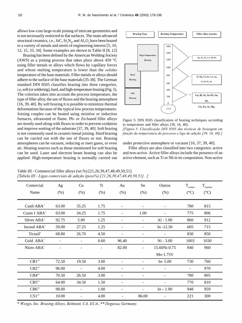
Physical vapor deposition - PVD - can be used to depositmetallic films onto ceramic surfaces. Vapor production andtransport to the substrate take place by low-pressure physicalphenomena. Ion plating is an important example of a PVDprocess (Fig. 9a). A metal is vaporized, ionized and acceleratedtowards a ceramic substrate by a bias potential. Arc ion platingis a variation of this technique. It employs a DC source andtakes place at higher working voltages thus improving theefficiency of metal ionization [74, 75]. Sputtering is anotherPVD process (Fig. 9b). It has been largely used to depositmetals onto optical devices and magnetic heads. Sputteringconsists in ionizing a gas, usually argon, using either a DC orRF (radio frequency) source. The ions are then speeded uptowards a metallic target whose atoms are then pulled out bythe resulting ionic bombardment. The sputtered atoms fromthe target are ionized and accelerated towards a ceramicsubstrate. An important feature of sputtering is thatstoichiometric films can be formed. Moreover, it is possibleto use elements with considerably different vapor pressures ata single temperature [74-77].
Sputtering film deposition can be carried out in a plasmareactor at approximately 100 mTorr (0.13 mbar) and flowinginert gas (e.g., argon). In a DC discharge, the target acts as thecathode of the process and is connected to the negative pole
of the high-tension source (-V). The ceramic substrate worksas the anode of the discharge and is either grounded or undera floating potential [75, 77]. As an abnormal discharge isgenerated between cathode and anode of a plasma reactor,positive argon ions are produced and driven towards the target(negative potential) colliding with it. The momentum transferthat results from these collisions produce other phenomena.For example, atoms are ejected from the surface of the targetin all directions of the plasma chamber. Some of them hit theceramic substrate and form a film [75]. Sputtering is not arecent technique. It has been used since 1877 but is underconstant development. Special interest for this process comesfrom its versatility. Adherent and dense films from virtuallyany material, including multicomponent and alloy targets, canbe formed and deposited [75, 77, 78].
Chemical Vapor Deposition – CVD - processes are also apossibility. Heterogeneous chemical reactions take place onthe surface of the ceramic substrate. The pressure of the gas inthe reaction chamber ranges from 103 to 104 Pa. The productionof high-quality CVD coatings requires appropriate reactionchambers and substrate temperatures around 1000 °C. Withplasma-assisted CVD it is possible to produce metallized
Figure 9: Film deposition by (a) PVD and (b) sputtering.[Figura 9: Deposição de filme por (a) PVD e (b) sputtering.]
(a)
(b)
R. M. do Nascimento et al. / Cerâmica 49 (2003) 178-198

188
ceramics at lower temperatures. Examples of plasma-assistedCVD include amorphous silicon films deposited ontophotovoltaic cells and thin films onto transistors [74, 75].
The Moly-Mn process has been widely used for many yearsand is reported to be one of the first metallization techniquesapplied to join metals to ceramics, mainly Al2O3. The approachconsists in sintering metallic powders on ceramic surfaces. Dueto its elevated sintering temperature, Al2O3 is metallized withrefractory metals. Molybdenum and tungsten are often usedbecause of their low coefficient of thermal expansion [12, 79].Different metallizing pastes containing Mo and Mn powderscan be dissolved in a solvent and used (Table V). A glassyphase is added to the paste for joining highly pure ceramicswith less than 3% amorphous grain boundary phases, especiallySiC and some types of Si3N4 [12, 39, 79].
A schematically diagram of the process is shown in Fig.10. A thin layer of a metallizing paste is applied onto a ceramicsurface which is subsequently heated to 1300 °C - 1600°C in amoist nitrogen-hydrogen (75%N2 –25%H2) atmosphere. Underthese conditions, the vitreous phase present in the bulk of theceramic substrate moves to its surface by capillary forces andreact with Mn at around 1400°C forming spinels, such asMnAl2O4 (when joining Al2O3). Simultaneously, Mo particlesare sintered onto the spinel layer, whose main function is tolink the ceramic substrate to the metallic film formed [39, 69,80]. Although the method requires an additional high-temperature step, ceramics previously metallized by the Mo-Mn process are commercially available. Metallized ceramicscost approximately 30% more [39].
An alternative metallization route is the TiH2 process. Acoating layer of TiH2 powder dissolved in nitrocellulose ismanually applied to the ceramic surface. Upon heating to thebrazing temperature, the hydride dissociates around 450 °C
and a direct contact between the ceramic surface and Ti isestablished. Brazing is accomplished using conventional filleralloys with no active metal [81].
Si3N4 has been metallized using Ti salts. A mixture of NaCland KCl containing 5 to 10 wt.% of a Ti-F-K compound isprepared and placed in a furnace at 700 e 1100 ºC under argon.Si3N4 parts are then immersed in the molten mixture severaltimes until reaction occurs between the ceramic and the saltsproducing a metallic layer. Next, the ceramic is cleaned, driedand brazed [71, 73]. Drawbacks associated with the methodinclude: i) the ceramic is entirely metallized which alters theproperties of surfaces which are not brazed, ii) the process islong and requires a specific furnace for melting salts and iii)the method is not environmentally safe as the chemicals usedand the residues are toxic.
Another commercial metallization method was developedby Sameer (Society for Applied Microwave ElectronicsEngineering and Research of India). The solution metallizationmethod consists in applying a water-soluble ink containing ~90 % ammonium molybdenate and 10 % potassiumpermanganate to alumina substrates and placing them at1050°C under moist hydrogen. Although simple, the processrequires successive inking and heating to form metallic filmsthat allow for brazing. The method is time and energyconsuming [72].
Finally, the mechanical metallization is a new, simple andfast method to metallize ceramics. It was developed andpatented by the Jülich Research Center, in German(Forschungszentrum Jülich). The process has been initiallystudied for the metallization of alumina and zirconia with Ti[82-84].
Mechanical Metallization
Planar ceramic surfaces can be mechanically metallizedby frictioning a metal against them. Preliminary experimentshave been carried out using either cone-shaped or (and) planartools made of titanium. Al2O3 and non-oxide ceramics – SiCand Si3N4 - have been mechanically metallized with Ti and
Mo (wt.% Mn (wt.%) Additional
elements (wt.%)
80 20 -
80 10 10 TiH2
75 20 5 Si
75 20 5 Mo2B5
75 20 5 Glass
80 14 6 Iron-Silicon
75 20 5 V2O5
80 -2 0 Glass
(MnO-Al2O3-SiO2)
70 20 10 MoB4
Table V - Composition of some pastes used in the Mo-Mnmetallization process [39].[Tabela V - Composição de algumas pastas utilizadas nametalização pelo processo Mo-Mn [39].]
Figure 10: Schematics of ceramic surface metallized by the Mo-Mnprocess (after [39]).[Figura 10: Representação esquemática de superfície cerâmicametalizada pelo processo Mo-Mn (adaptado de [39]).]
R. M. do Nascimento et al. / Cerâmica 49 (2003) 178-198

189
subsequently brazed to low-expansion alloys and stainless steel.Conventional tool machines can be used just adapting a deviceto generate and control the relative movement between metaland ceramic (Fig. 11) [82]. The process is based on the wearand deposition of a metal as it is frictioned against a harderceramic surface.
Numerous advantages are associated with this process [82]:a) Conventional tools can be used;b) Metallization occurs at room temperature;c) No chemicals are used and no hazardous residues are formed.The process is environmentally safe;d) Large choice of coating metals or alloys;e) Selection of coating area;f) Easy automation of the process and adaptation for non-planarsurfaces andg) Applicable to batch and large scale production
Mechanical metallization with Ti and subsequent brazingof alumina substrates has been investigated. Conventionalactive metal free filler alloys have been used. Ti reacts withalumina and molten Ag/Cu and Au/Ni alloys at the brazingtemperature resulting in a thin reaction layer (equation I)responsible for the microstructural connection between filleralloy and ceramic substrate. As a reaction layer is formed, Tialso dissolves in the molten filler alloy forming other interfacialphases [8, 85].
2Al2O3 + 3Ti → 4Al + 3TiO2 (J)
Studies on mechanical metallization of alumina with Ti haveshown that the quality of the metallic film deposited onto theceramic is strongly affected by process parameters. These canbe adjusted within wide ranges in order to optimize the qualityof the films. The films are characterized by a distribution ofvoids. According to the number and size of these voids,
microstructural defects can be formed. Fig. 12 shows the filmand distribution of defect size of a Ti-film mechanicallydeposited onto alumina. Roughly 80% of the defects arebetween 0.010 mm and 0.023 mm in diameter and ~ 95% ofall defects are smaller than 0.05 mm in diameter [8, 85].
The mechanical metallization process is experimentallysimple and straightforward but its rationalization is rathercomplex. It involves equations from the classical mechanicalto model the dynamic friction between contact surfaces; surfacewear also has to be considered and requires knowledge on theelastic and plastic properties of the tribological couple andtheir dependence with temperature. Thermal phenomena arealso important since heat generation, dissipation and flowtowards the metallic and ceramic components affect the filmdeposition [8].
Finally, the ceramic counterpart should be carefullycharacterized. Disadvantageous combinations of metallizationparameters and surface roughness can lead to brittle fracture andchipping as a result of the relatively high force applied to themetallization tool against the ceramic surface as well as the vibration
Figure 11: Apparatus for mechanical metallization and processparameters.[Figura 11: Equipamento para metalização mecânica e parâmetrosde processo.]
R. M. do Nascimento et al. / Cerâmica 49 (2003) 178-198
Figure 12: Optical macrograph of Ti film mechanically depositeddeposited (top); defect size distribution (bottom).[Figura 12: (a) Macrografia ótica de filme de Ti depositadomecanicamente (acima); distribuição de tamanhos de defeitos(embaixo).]

190
and corresponding impact of the metallization system [8].Adhesion of the Ti film onto the ceramic takes place by
particle interlocking and physical bonding. Metallizationoccurs at room temperature, which is insufficient to dissociatethe ceramic with contact with Ti and to form interfacialcompounds [8].
The thickness of typical Ti films mechanically applied ontoceramic substrates is of the same order of magnitude of Rz,i.e., the roughness parameter for the ceramic. Films depositedonto alumina were about 5 ± 2 µm thick (Fig. 13).
BRAZING
Brazing has been extensively investigated and employedfor metal/ceramic joining. The process does not require costlyequipment and can be easily automated. Strong and heat-resistant joints are commonly produced in large number [4,41, 86, 87]. Great efforts have been focused on improvingreliability and reproducibility of the process. Superior qualitydirectly depends on the adherence of the filler alloys to thesurfaces of the base materials and the ductility of eventualinterfacial reaction compounds [35, 36, 38, 43]. New routeshave been developed mainly to improve wetting of the filleralloys to ceramic substrates [88, 89]. For instance, oxideceramics such as Al2O3 and SiO2 can be superficially treatedwith high power laser beams. A thin layer of ceramic material(50 µm – 100 µm) is melted. This significantly reduces thecontact angle with the filler alloy [8, 90, 91]. Pre-oxidation ofSiC has also been carried out in an attempt to improve wettingwith commercial Ti-based filler alloys, such as (Cusil, CusilABA, and Incusil). Reactions involving Ti and the ceramicsurfaces, SiC and SiO2, an their effect on the contact anglehave been studied [49].
Ceramic/metal and ceramic/metal brazing were originallycarried out following metallization of the ceramic surface(s)using the conventional Moly-Mn method. This can be attributedto the domain of the metallization technique and the price and
difficulty associated with obtaining active filler alloys. Directbrazing using active filler alloys is a single step process thatdoes not require furnaces capable of operating between 1300and 1500 °C, necessary for metallization with Moly-Mn. Thisis a very attractive feature when considering production atcommercial scale. The development of active alloys containingTi played a very important role in expanding the use of directbrazing [53, 92]. Significant research was directed towardsoptimizing technological parameters and describing themetallurgical reactions that took place during the process asthe basis to determine interfacial microstructure.
Different active elements can be used in filler alloys: Nb,Ti, Ta, Zr, Hf. By far, Ti is the most common one. Theychemically react with the ceramic surface, promotingdissociation and formation of a reaction zone [5, 44, 53].Because of the high affinity of these elements for oxygen, brittleoxide layers, such as TiO2 and NbO2, easily form in the ceramic/filler alloy interface. Although useful for establishing achemical bridge between the base materials, excessivebrittleness is deleterious to the mechanical strength of the joint,as it reduces the ability of the couple to absorb residualthermomechanical stresses. Optimizing parameters means thatthe contents of the active element should allow for a balancebetween maximizing wetting and minimizing the contents ofinterfacial oxides.
Another growing research area in ceramic brazing concernsthe development of active filler alloys but no noble metals(Ag, Au). Alloys such as CuNiTiB, CuGaTi, and In-Ti havebeen used to braze nitride ceramics [22, 25, 93]. Ti has alsobeen replace by Zr in Al2O3/alloy steels brazing [94]. High-temperature joints have also been brazed using high-meltingpoint Au-Ni-Mo filler alloys containing V as active element.Ni-Cr-Si alloys have been used to braze Si3N4 [23, 24, 95]. Asa general goal, the reactions between a number of structuralceramics and filler alloys in both direct and indirect brazinghave been studied. The thermodynamics of interface formationbetween ceramics and different filler alloys has also been objectof studies. [9, 21, 27, 95-97].
The formation of a reaction zone between a ceramic and afiller alloy depends on the activation of chemical reactions[11]. The reactions that form an interface take place only whenthe formation of a new phase reduces the Gibbs free energy ofthe system. For their nature, they should be described by thethermodynamics of irreversible processes where their entropyis determined by the chemical potential, mass, and heat flowof the reacting species [11]. As such data is not readily availablefor the vast majority of ceramic/metal combinations,equilibrium thermodynamics is often applied as firstapproximation. The behavior of a system is described by thevariation in the Gibbs free energy, ∆G, of the reactions whichare likely to occur [5, 11].
Al2O3 has been joined to metals using filler alloyscontaining Ti. Alumina is more stable than titanium oxides.The reduction of alumina to form a reaction layer isthermodynamically possible because it is limited to the surface.Reduction of surface material requires less energy than forbulk material, i.e, ∆GAl2O3
Sup. >∆GAl2O3o [53]. Reaction
Figure 13: SEM image of Ti film on Al2O3.[Figura 13: Imagem eletrônica de filme de Ti em Al2O3.]
R. M. do Nascimento et al. / Cerâmica 49 (2003) 178-198

191
between dissociated surface atoms from the ceramic and themolten filler alloy is represented by
Al2O3sup. + 3x M ⇔ 3MxO + 2Al (L)
where M represents the active metal of the filler alloy [53,98], and grants the necessary ceramic wetting to promotejoining.
Ti from Cu-Ag based active alloys reacts superficially withalumina forming a thin layer of oxides, whose stoichiometry,TiO, Ti2O3, Ti3O5, Ti4O7 or TiO2, depends on the activity of Tiin the filler alloy [15, 98-100]. A second layer of reactionproducts can be formed on top of the primary oxide zone andis originated from the reaction of Ti with Cu from the filleralloy, resulting in mixed Cu-Ti oxides [46, 101]. Fig. 14represents a general aspect of an interface between aluminaand Ag-Cu-Ti. A good agreement could be established betweenexperimental results and the proposed distribution of reactionproducts from equilibrium thermodynamic equations for thatparticular system.
In the chemical equations written in Fig. 14, Al from thereduction of alumina and Ti which is originated from the filleralloy and is responsible for such reduction depict are bothdissolved in Cu. This is symbolized by Al(Cu) and Ti(Cu) [46,101]. At the brazing temperature, Ti segregates and movestowards the surface promoting the dissociation of alumina intoaluminum and oxygen. The latter react with Ti according toequation (J) forming the primary oxide layer, which rapidlycoats the entire surface of the ceramic [46]. In the formationof the mixed Cu-Ti oxide, Al(Cu) is now dissolved by Cu-Ti-O[46, 101]. It should also be mentioned that oxygen from thefiller alloy and the brazing atmosphere can also oxidize Ti,since the partial pressure of oxygen in the brazing atmosphere(at about 1.0 x 10 -6 mbar) is far greater than that necessary toprevent the oxidation of Ti, i.e., 1.0 x 10 -19 mbar [44].
Ti-oxides from layer 1 are almost as stable as alumina,which prevents wetting of the Ag-Cu alloy. Reaction layer 2 isformed by a mixed oxide, which wets the Ti-oxide (layer 1)and promotes the formation of a transition structure responsiblefor the structural link between ceramic and filler alloy [101].Since Ti moves towards the surface of the ceramic, it shouldbe expected a reduction in the Ti contents at the remainder ofthe interface microstructure (filler alloy) at the brazing
temperature.Ticusil is a commercial filler alloy with 4.5 wt.% Ti and is
extensively used to braze alumina. The microstructure ofbrazed Al2O3/Fe-28Ni-18Co interfaces using Ticusil has beencharacterized as a function of the brazing time [102]. Thepresence of a Ti-rich reaction layer and intermetallic phasescould be established. The formation and distribution ofinterfacial reaction products from have been extensivelyinvestigated to assist in the interpretation of the mechanismsinvolved in interface growth. Both thermodynamic and kineticaspects have been taken into account [1, 46, 99, 101]. IncusilABA (Ag-Cu-Ti-In) is also widely used as filler alloy in metal/ceramic joining. It has been shown that both the thickness ofthe reaction layer and its Ti contents are affected by the brazingcycle. The microstructure of a brazed joint using Incusil isshown in Fig. 15, revealing the existence of a reaction layer incontact with alumina.
Indirect brazing of ceramics to metals can be accomplished
using conventional (non-active) and inexpensive filler alloyson metallized ceramics. Other metallization techniques havebeen simultaneously developed as an alternative to the Moly-Mn process and the use of active filler alloys [75, 82] in anattempt to reduce costs. It is evident, however, that novelapproaches for brazing in large scale should not requireexpensive machinery, numerous steps or high temperaturefurnaces [79, 82]. Mechanical metallization is an interestingsolution in this case. Alumina and non-oxide ceramics havebeen mechanically metallized with Ti and subsequently brazedto Cu or low expansion alloys (kovar and vacon 70) usingconventional filler alloys without active metal [8].
In joints brazed after mechanical metallization of theceramic, the interaction between filler alloy, Ti-film andceramic substrate resulted in the precipitation of a reactionlayer and Ti-containing intermetallic phases. It is in theprecipitation zone that the filler alloy reacts with Ti (Fig. 16)
Figure 14: Schematics of Ag-Cu-Ti/Al2O3 interface.[Figura 14: Ilustração de interface Ag-Cu-Ti/Al2O3.]
Figure 15: Reaction layer of joint brazed at 750 °C for 30 min usingIncusil ABA.[Figura 15: Camada de reação de junta brasada a 750 °C durante30 min utilizando Incusil ABA.]
R. M. do Nascimento et al. / Cerâmica 49 (2003) 178-198

192
whereas the reaction layer results from the reaction betweenthe ceramic substrate and Ti. The microstructure of brazedjoints after mechanical metallization shows a well-definedprecipitation zone, generally more accentuated than thatobserved in brazed joints with active filler alloys. On the otherhand, reaction layers on metallized surfaces are normallydiscontinuous. The reactions between active filler alloy andceramic substrate usually take place above 850 ºC [1].However, with the mechanical metallization the intermetallicprecipitation and reaction products were formed at 820 ºC [85].
Reaction layers on metallized brazed joints were usuallybetween 2 and 4 µm thick as a result of the wavy anddiscontinuous aspect of the deposited Ti-films. In defect areas,wetting took place because the filler alloy becomes active,however, the local availability of Ti is lower at these pointsthus reducing the thickness of the reaction layer. At the brazing
temperature, Ti from the metallic film is in the solid state andforms an interface with the liquid filler alloy (Fig. 17). As theprocess takes place, Ti from that interface is dissolved by thefiller alloy forming an active filler, which extends itself to about25 µm from the ceramic surface. The increase in Ti contentsin the filler alloy ultimately results in the formation of theprecipitation zone.
MECHANICAL BEHAVIOR
Ideally, the mechanical strength of a ceramic/metal jointcomponent should be higher than those of its constituents. Thejoint should fail at one of the base materials. In reality, jointsfail at lower strengths, either because of the interfacial strengthis inherently lower or because of residual stresses which lowerthe strength of the ceramic counterpart. Effective joining shouldgrant strength levels compatible to the demand of the intendapplication along with maximum reliability [103]. Jointstrength is mainly determined by
• Joining process and related parameters. The strength ofbrazed joints, in particular, depend on the quality of themetallized layer (when present), filler alloy, and brazing cycle;
• Intrinsic properties (Young modulus and coefficient ofthermal expansion) and characteristics (roughness andtoughness of the ceramic) of the base materials, especially theceramic for its brittle nature and
• Joint type (planar or fitted) and geometry (cylindrical orrectangular).
However, a fundamental aspect on ceramic/metalmechanical strength is the composition and microstructure ofthe interface. The presence of intermetallics (usually brittle)along with the thickness and morphology of reaction layerscan drastically enhance or dwindle the strength of the joint.The presence of organic material or impurity particles eitheron the surfaces to be joined of in the filler alloy (for brazing)is deleterious to the interfacial microstructure. Joining defectsare created. These areas of joining discontinuities increase local
Figure 16: Overall aspect of Cu/Al2O3 joint brazed at 820 ºC, usingAg-Cu euthetic as filler alloy.[Figura 16: Aspecto geral de junta Cu/Al2O3 brasada a 820 ºCutilizando-se o eutético Ag-Cu como liga de adição.]
Figure 17: Schematic drawing showing the formation of active alloyand reaction layer in a defect zone [munchen].[Figura 17: Ilustração do mecanismo de formação de liga ativa ecamada de reação em zona de defeito. ]
Figure 18: Schematic representation of possible defects present in jointcomponents [5].[Figura 18: Representação de possíveis defeitos presentes em juntas [5].]
R. M. do Nascimento et al. / Cerâmica 49 (2003) 178-198

193
stresses and promote crack nucleation and growth (Fig. 18)[5, 11, 102, 103]. In particular, ceramics are quite susceptibleto the presence of microcracks and areas of high local stresses.Upon cooling, the ceramic is often submitted to tensile stressescapable of growing existent cracks and nucleating new ones.
In addition, controlling the thickness of interfacial oxidelayers calls for additional caution. Usually brittle, reactionoxide layers can be the limiting aspect on the mechanicalstrength of otherwise sound joints and should be characterizedby statistical analyses and represented by Weibull plots [5, 11,12, 104]. As for ceramics, joint strength should be characterizedby statistical analyses. Tensile, flexural (3- or 4-point bending)and shear tests are commonly used [5, 11, 12]. Fig. 19 illustratesthe sample geometry and test configuration used in themechanical characterization of ceramic/metal joints. Accordingto Weibull’s weak link theory, tensile tests are the mostappropriate approach [104]. The volume under tension ismaximum and the result is representative of the whole testspecimen. However, close tolerances and expensive machiningdue to the large number of samples required are limitingaspects. Results are characterized by large scattering.
Although specimens for bending tests also require adequatefinishing to assure planar and parallel surfaces, tight tolerancesare more paramount and the alignment between sample andtest machine is easier to accomplish. Scattering is also reduced
and therefore, the results are more reliable. Higher values aremeasured compared to tensile tests since the volume undertension is smaller [104, 105]. Comparing the volume undertension, V, and the strength resulting from tensile and 3- and4-point bending tests yield
Vtensile >V 4p-bending >V3p-bending ⇒ σtensile < σ4p-bending < σ3p-bending (M)
Weibull’s statistical method should make it possible totransfer results from one test to another taking into accountthe differences in volume under tension. Although applied tomonolithic ceramics with reasonable success the approach hasnot yielded satisfactory results for joint strength [12,104].Transfer rates from tensile tests to 3-point bending of x 1.7were calculated for Si3N4 - Al - Invar joints. Experimentalvalues were about 2.5. Major sources of errors can be attributedto differences between the calculated and real stressdistributions, presence of residual stresses, and plasticdeformation upon test loading [5, 12].
Residual stresses result from mismatches in the coefficientof thermal expansion and elastic modulus of the base materials.Upon cooling from the relatively high joining temperatures,characteristic of usual joining processes, the interface restrictsthe contraction of the material, concentrating local stresses [5,11]. The magnitude and distribution of residual stresses in andaround ceramic/metal interfaces depends on a number ofaspects, such as joint geometry, joining temperature, thicknessand composition of reaction layers, in addition to intrinsicmechanical properties of the base materials [4, 5, 14].
Thermal stresses affect the results from mechanical testsand increase their scattering [4, 5]. For cylindrical samples,the magnitude of thermal stresses increases with the diameterof the sample and reach its maximum near the border. Thesharp edges of rectangular specimens also concentrate stresses[4,5]. Minimizing residual stresses significantly contributesto increasing both the mechanical strength and reliability ofjoint components. Different approaches related to design andprocess can be used to reduce stresses.
Joint geometry can be optimized to avoid areas of stressesconcentration and maximize strength. Measures should also betaken towards minimizing property mismatches. Ductile metallayers (e.g. copper or aluminum) can be inserted at the interfaceto accommodate stresses [5,12] whereas refractory metals andexpansion-controlled alloys (Invar, Kovar and Superinvar) canbe used to promote a gradual transition from the ceramic to themetal, thus reducing CTE mismatches [4, 5, 12].
The evaluation of thermal residual stresses can beperformed either experimentally (X-ray or neutron diffraction)or numerically using the Finite Element Method (FEM) [5].X-ray diffraction is far more employed than neutron diffractiondue to experimental availability. A disadvantage associated withthe method consists in the limited penetration of the radiationinto the material. Stress analysis is limited to shallow depthsand bulk stresses cannot be assessed. Neutron diffraction, onthe other hand, provides full penetration but requires longerdata collecting periods and a neutron source [5].
The numerical approach, FEM, has been widely used to
Figure 19: Sample geometry for mechanical tests of joined specimens.(a) tensile; b) 3-point bending, (c) 4-point bending, (d) plain shearand (e) shear on ring/cylinder.[Figura 19: Geometrias de amostras para ensaios mecânicos dejuntas: (a) tração; b) flexão 3-pontos, (c) flexão 4-pontos, (d)cisalhamento simples e (e) cisalhamento em anel/cilindro. ]
R. M. do Nascimento et al. / Cerâmica 49 (2003) 178-198

194
evaluate residual stresses [11, 106, 107, 108]. Simpler, faster,and much cheaper than the experimental techniques, complete2- or 3-dimensional stress maps can be obtained. The key tosuccessful numerical analyses relies on the selection ofmaterials property, the proposed mechanisms for interfaceformation, and the development of elastic or elastic-plasticdeformation models [5]. Modeling of complex and thickreaction layers (~ 3 µm) can be extremely complicated andnormally induce erroneous responses.
The basis for the diffraction techniques is the peak shiftthat accompanies lattice distortion due to the presence ofresidual stresses. Neutron diffraction experiments depend onthe availability of a neutron source, however the results providevaluable information on the distribution of stresses not onlynear the edges but also in the bulk of joined components.Neutron diffraction analyses rely on establishing differencesbetween the angular position of specific peaks comparingstress-free reference sample and joined components. Apolychromatic neutron beam in generated at the source andcollimated toward a monochromator crystal. Themonochromatic hits a sample normally placed on top of amoving table. The spatial position of the sample is adjustedby a set of independent stages. The x- and y-coordinates areusually variable and the z-coordinate fixed (Fig. 20). The beamheight can be set to be greater than the sample height in orderto integrate the diffraction process through the entire sample,i.e., along the y-axis. The diffraction angle is given by
φ = 2θ (N)
where θ is the Bragg angle. Values of φ should be chosen inorder to maximize the intensity of the diffracted peak andminimize distortion of the sampling volume (φ ≈ 90°). It shouldbe noted that the intensity of a neutron beam is far less thanthe intensity of an X ray beam. Strains can be defined as [109]
(O)
where d corresponds to the spacing between a particular set ofcrystallographic planes under tension or compression. If thesample is under tension, the planes are pulled slightly apart sothat d increases with respect to a strain-free value, do.Conversely, if the sample is under compression, the planes arepushed together and d decreases with respect to do. The angleof rotation of the table (ψ) is adjusted to select the geometryof the diffraction process and, therefore, the strain componentunder investigation. The normal component of strain (εz) isstudied by setting ψ equal to φ/2, and the in-plane component(εx) by setting equal ψ equal to φ/2 + 90°. The stresses arethen calculated according to
(P)
where E is the elastic modulus, and v is the Poisson’s ratio. Acyclic permutation of indices yields the other two componentsof stress (σy and σz). Although for symmetric samples, it isusually assumed that strains along both in-plane componentsare equivalent (εx = εy), this is somehow an oversimplification.From a mechanical standpoint, the only area that satisfies thisassumption is situated on the middle edge z of the sample, andrigorously, εx is different from εy almost everywhere. On theother hand, εx is a result of an integrated measurement alongthe entire height of the sample. Thus, when measurements wereperformed along the z-axis, εx may be recognized as arepresentative value of the middle point of the transversalsection and, hence, the hypothesis is applicable.
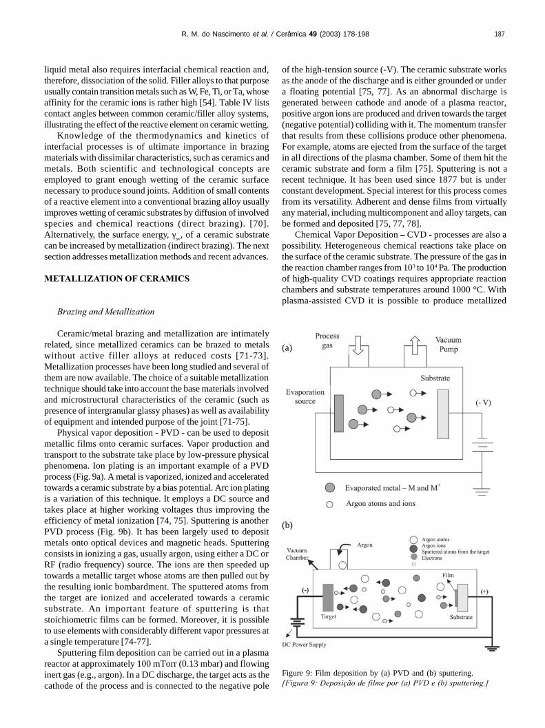
Results obtained from hot-pressed SiC-Mo joints withrectangular cross section are shown in Fig. 21 [109].
The distribution of residual stresses in SiC-Mo joints wasstudied along a line perpendicular to the SiC/Mo interfaces(Fig. 21a). Maximum σx stress (330 MPa) was measured onthe molybdenum side of the joint at a distance of 0.25 mmfrom the interface (Fig. 21b). On the SiC side, a correspondingvalue of -150 MPa was measured at an equivalent distancefrom the interface. SiC was in compression in the direction ofσx, whereas molybdenum was in tension. Evidently, thisoccurrence was a result of the CTE mismatch between thematerials. Molybdenum has a higher CTE than SiC; therefore,it contracted more during cooling of the joint from the joiningtemperature. However, its contraction was restrained by itsbonding to SiC, thus resulting in compressive stresses on theceramic side. Molybdenum reacted to that tendency, trying toextend the interface, yielding the concentration of tensilestresses, especially near the interface with SiC. On both theceramic and metal sides, the amplitude of σx decreased as thedistance from the interface increased. On the SiC side, σx wasalmost zero at a distance of 1.5 mm, whereas on themolybdenum side, residual stresses were measured at an
Figure 20: Neutron diffraction setup to evaluate residual stresses inceramic-metal joints.[Figura 20: Montagem de equipamento de difração de nêutrons paraanálise de tensões residuais em juntas cerâmica-metal.]
R. M. do Nascimento et al. / Cerâmica 49 (2003) 178-198

195
equivalent distance, as a result of the plastic deformation ofthe metal. In contrast, σz remained nearly null (within themargin of error) for most of the region analyzed, with anoscillating pattern that resulted in slight tension on the metalside and compression on the ceramic side. This behavior wasconfirmed by FEM analysis. To that end, a tridimensionalthermal elastoplastic model was generated to study those joints.A preliminary analysis was performed considering bothmaterials as ideally linear-elastic components. Subsequently,a model where only the ceramic was considered to be linear-elastic throughout the thermal loading was constructed. In thiscase, the metallic component was modeled considering anelastic-perfect-plastic behavior, the von Mises yield criterion,and the associative Prandtl-Reuss flow rule. The program usedallowed the constitutive behavior to be modeled usingkinematic hardening, as very low values of the tangent moduluswere involved, i.e., ET/E = 0.05. Because of the typically highjoining temperatures, the variation of the mechanical propertiesof the material with temperature must be considered, especiallyYoung moduli, linear coefficients of thermal expansion, as wellas yield strength and tangential modulus of the metal. Poisson’sratio could be assumed to be constant. The symmetry of thejoined couple with respect to geometry, mechanical properties,and loading may allow significant simplification of the model.Only one quadrant of rectangular joints, such as that illustrated
in Fig. 22 [109], can be modeled. A sequence of finite-elementmashes was then built. Firstly, a uniform mesh composed oftrilinear hexagonal elements was considered. Subsequently,to improve the accuracy of the analysis near the interface(region of stress concentration), a triquadratic mesh wasconsidered (Fig 22b). In addition, sample cooling was assumedto occur free from mechanical loads. The temperaturedistribution inside the diffusion couple was assumed to beuniform, to avoid the need to solve a heat-transfer equationduring the iterative process. This assumption is quitestraightforward considering that cooling times are usually longenough considering the thermal diffusivity of metals and therelatively limited size of the joints. Creep effects were notconsidered.
A comparison of numerical and experimental results (Fig.23) showed a reasonable agreement between experimental andcalculated values for the σx stress component of SiC-Mo joints,especially on the ceramic side of the joint. Further refinementof the numerical model must include creep effects andviscoplastic relief of the metal.
FEM analyses may also provide a complete map of all stresscomponents, including shear stresses, which are particularlyhard to obtain experimentally. An example of normal and shearstress maps obtained from Fe-Ni-Co/Al2O3 brazed joints isshown in Fig. 24 [110].
Figure 21: (a) neutron scan line and (b) stresses calculated fromneutron diffraction data on SiC-Mo interface.[Figura 21: (a) Linha de varredura de nêutrons e (b) tensõescalculadas a partir de difração de nêutrons em interfaces SiC-Mo.]
Figure 22: (a) Overall sample and modeled quadrant and (b) modeled mesh.[Figura 22: (a) Amostra e quadrante modelado e (b) detalhe da malha.]
R. M. do Nascimento et al. / Cerâmica 49 (2003) 178-198
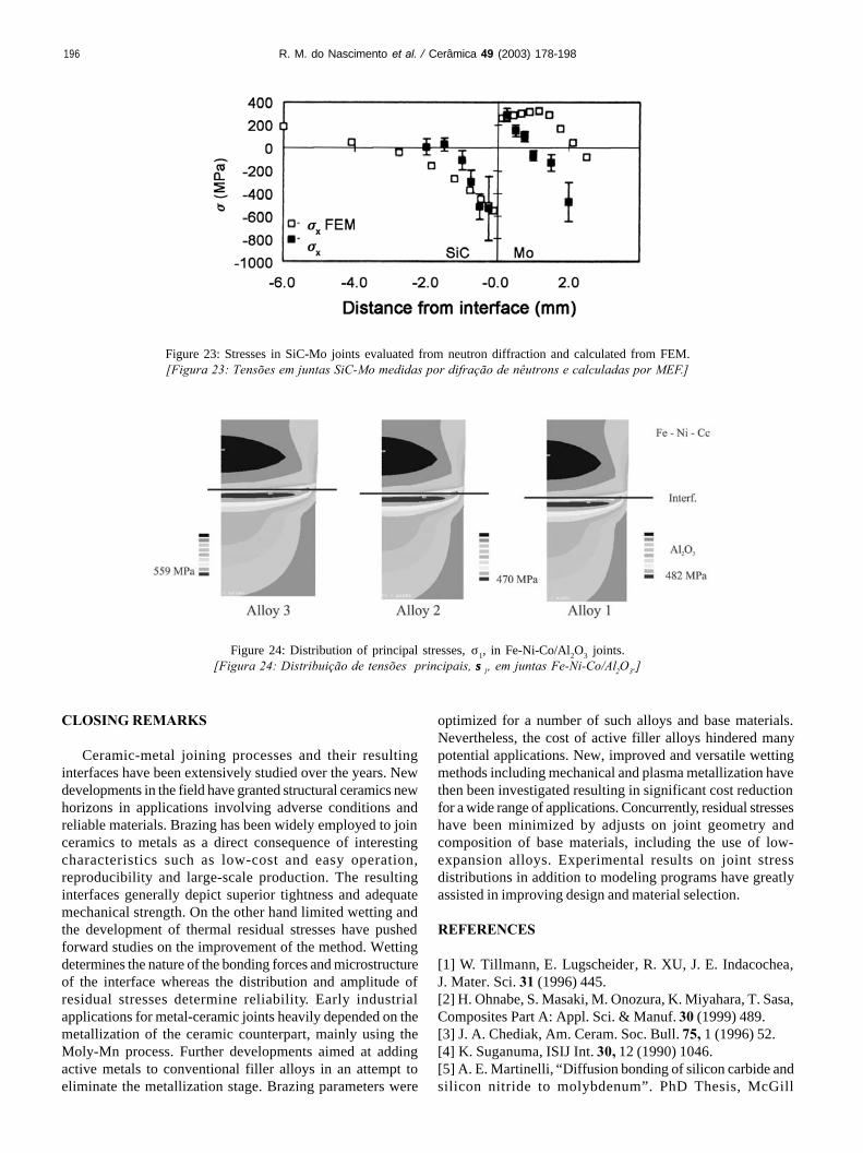
196
CLOSING REMARKS
Ceramic-metal joining processes and their resultinginterfaces have been extensively studied over the years. Newdevelopments in the field have granted structural ceramics newhorizons in applications involving adverse conditions andreliable materials. Brazing has been widely employed to joinceramics to metals as a direct consequence of interestingcharacteristics such as low-cost and easy operation,reproducibility and large-scale production. The resultinginterfaces generally depict superior tightness and adequatemechanical strength. On the other hand limited wetting andthe development of thermal residual stresses have pushedforward studies on the improvement of the method. Wettingdetermines the nature of the bonding forces and microstructureof the interface whereas the distribution and amplitude ofresidual stresses determine reliability. Early industrialapplications for metal-ceramic joints heavily depended on themetallization of the ceramic counterpart, mainly using theMoly-Mn process. Further developments aimed at addingactive metals to conventional filler alloys in an attempt toeliminate the metallization stage. Brazing parameters were
optimized for a number of such alloys and base materials.Nevertheless, the cost of active filler alloys hindered manypotential applications. New, improved and versatile wettingmethods including mechanical and plasma metallization havethen been investigated resulting in significant cost reductionfor a wide range of applications. Concurrently, residual stresseshave been minimized by adjusts on joint geometry andcomposition of base materials, including the use of low-expansion alloys. Experimental results on joint stressdistributions in addition to modeling programs have greatlyassisted in improving design and material selection.
REFERENCES
[1] W. Tillmann, E. Lugscheider, R. XU, J. E. Indacochea,J. Mater. Sci. 31 (1996) 445.[2] H. Ohnabe, S. Masaki, M. Onozura, K. Miyahara, T. Sasa,Composites Part A: Appl. Sci. & Manuf. 30 (1999) 489.[3] J. A. Chediak, Am. Ceram. Soc. Bull. 75, 1 (1996) 52.[4] K. Suganuma, ISIJ Int. 30, 12 (1990) 1046.[5] A. E. Martinelli, “Diffusion bonding of silicon carbide andsilicon nitride to molybdenum”. PhD Thesis, McGill
Figure 24: Distribution of principal stresses, σ1, in Fe-Ni-Co/Al2O3 joints.[Figura 24: Distribuição de tensões principais, σσ1, em juntas Fe-Ni-Co/Al2O3.]
Figure 23: Stresses in SiC-Mo joints evaluated from neutron diffraction and calculated from FEM.[Figura 23: Tensões em juntas SiC-Mo medidas por difração de nêutrons e calculadas por MEF.]
R. M. do Nascimento et al. / Cerâmica 49 (2003) 178-198

197
University, Montreal, Canada (1996).[6] M. G. Nicholas, Advanced Joining Technologies, Proc. Int.Inst. Welding Congress on Joining Research (1990) 161.[7] R. D. Watkins, ASM Handbook, Ceramics and Glasses,Vol. 4 (1991) 478.[8] R. M. Nascimento, “ Metalização Mecânica de Al2O3 paraBrasagem Metal/Cerâmica”, D. Eng. Thesis, UFSC, Brasil(2001) in Portuguese.[9] O. C. Paiva, M. A. Barbosa, J. Mater. Sci. 35 (2000) 1165.[10] K. Suganuma, Mater. Res. Soc. Symp. Proc. 314 (1993) 51.[11] J. A. Howe, Intern. Mater. Rev. 38, 5 (1993) 257.[12] J. T. Klomp, G. De With, Mater. & Manuf. Proc. 8, 2(1993) 129.[13] M. M. Schwartz, Ceramic Joining, ASM International, 1990.[14] G. Elssner, G. Petzow, ISIJ Int. 30, 12 (1990) 1011.[15] O. M. Akselsen, J. Mater. Sci. 27 (1992) 1989.[16] M. Boretius, E. Lugscheider, W. Tillmann, “Fügen vonHochleistungskeramik: Verfahren-Auslegung-Prüfung-Anwendung”. VDI- Verlag GmbH, Düsseldorf (1995) in German.[17] L. Shepeleva, B. Medres, W. D. Kaplan, M. Bamberger,M.H. McCay, T. D. McCay, M. Sharp. Surf. & Coating Tech.125 (2000) 40.[18] V. Curicuta, D. E. Poulain, D. R. Alexander, R. J. de Angelis,S. Gasser, E. Kolawa, Mater. Sci. Eng. B 68 (2000) 186.[19] K. Suganuma, Mater. Res. Soc. Symp. Proc. 314 (1993) 51.[20] V. Curicuta, D. E. Poulain, D. R. Alexander, R. J. de Angelis,S. Gasser, E. Kolawa, Mater. Sci. Eng. B 68 (2000) 196.[21] T. H. Chuang, M. S. Yeh, Y. H. Chai, Metallurgical andMaterials Transactions A. 31A (2000) 1591.[22] D. Huh, D. H. Kim, J. Mater. Res. 12, 4 (1997) 1048-1055.[23] M. R. Rijnders, S. D. Peteves, Scripta Mater. 41, 10 (1999) 1137.[24] A. M. Hadian, R. A. L. Drew, J. Eur. Ceram. Soc. 19, 8(1999) 1623.[25] H. Xiong, C. Wan, Z. Zhou, Metallurgical and MaterialsTransaction A 29A (1998) 2591.[26] S. D. Peteves, M. Paulosto, G. Ceccone, V. Stamos, ActaMater. 46, 7 (1998) 2407.[27] M. Paulasto, J. Kivilahti, J. Mater. Res. 13, 2 (1998) 343.[28] J. Besson, J. L. Terrier, PH. Dubois, Metal. Trans. A 23(1992) 2791.[29] T. Itoh, H. Kimura, J. Eng. Gas Turbines and Power 115(1993) 42.[30] K. Takama, S. Sasaki, S. Shimizu, N. Kamiya, J. Eng.Gas Turbines and Power 115 (1993) 17.[31] Y. Katano, M. Ando, T. Itoh, M. Sasaki, J. Eng. GasTurbines and Power 115 (1993) 9.[32] H. Kawase, K. Kato, T. Matsuhisa, T. Mizuno, J. Eng.Gas Turbines and Power 115 (1993) 23.[33] B. Wielage, D. Ashoff. Aktivloeten von Ingenieurkeramik.Hart- und Hochtemperaturlöten: Vorträge des gleichnamigen9. Dortmunder Hochschulkolloquiums. DVS – Berichte band.132 (1990) 15 in German.[34] A. Guedes, A. M. P. Pinto, M. Vieira, F. Viana, Mater.Sci. Eng. A 301 (2001) 118.[35] American Welding Society, Welding Handbook, 7th Ed.,Vol. 2 (1978).[36] British Standards Institution, Guide to Brazing, Part 2:
Brazing, BS 1723 (1986).[37] K. Nogi, K. Oisshi, K. Ogino, Materials Transactions 30,2 (1989) 137.[38] DIN 8505 Standard T1 Löten; Allgemeines, Begriffe (Mai1979) und DIN 8505 T2 “Löten; Einteilung der Verfahren”,Begriffe (1979) in German.[39] R. Lison, Wege zum Stoffschluß über Schweiß- undLötprozesse. Fachbuchreihe Schweißtechnik, Band 131. Verlagfür Schweißen und verwandte Verfahren DVS - Verlag GmbH,Düsseldorf (1998) in German.[40] L. Dorn, P. Dorner, K. Iversen, J. Kinzel, H. Pelster, E.Lugscheider, H. Schchinger, Hartlöten: Grundlagen undAnwendungen. Expert Verlag, Sindelfingen (1985) in German.[41] J. A. Hamill Jr, Int. J. Powder Metal. 27, 4 (1991) 363.[42] R. Arróyave, T. W. Eagar, Acta Mater. 51 (2003) 4871.[43] M. M. Schwartz, Brazing, ASM Int. (1995).[44] E. Lugscheider, W. Tillmann, Mater. & Manuf. Proc. 8, 2(1993) 219.[45] M. G. Nicholas, T. M. Valentine, M. J. Waite, J. Mater.Sci. 15 (1980) 2197.[46] P. R. Chidambaram, G. R., Edwards, D. L Olson, Metal.& Mater. Trans. A 25 (1994) 2083.[47] WESGO, Inc. Brazing Alloy, Active metal alloyscatalogue, CA (1994).[48] Degussa AG, Loettechnik und Durferrit-Verfahren,Catalogue (2001).[49] J. Lopez-Cuevas, H. Jones H. V. Atkinson, Mater. Sci.Eng. A 266 (1999) 161.[50] D. Huh, D.-H Kim, J. Mater. Res. 12, 4 (1997) 1048.[51] R. K. Shiue, S. K. Wu, J. M. O., J. Y. Wang, Metal. &Mater. Trans. A 31 (2000) 2527.[52] D. J. Cawley, Introduction to Ceramic-metal Joining,Metal-Ceramic Joining, Eds.: P. Kumar, V. A. Greenhut - TheMinerals, Metals & Materials Society (1991) p. 3.[53] P. R. Chidambaram, G. R. Edwards, D. L Olson,Metallurgical Transactions B 23 (1992) 215.[54] A. M. Hadian, “Joining of silicon nitride-to-silicon nitrideand to molybdenum for high-temperature applications”, Ph.D.Thesis, McGill University, Montreal, Canada (1993).[55] J. A. Pask, A. P. Tomsia, Surfaces and Interfaces inCeramic and Ceramic-Metal Systems, Mater. Sci. Res. 14(1986) 411.[56] K. M. Martorano, “Molhamento e espalhamento deestanho e da liga 60%Sn-40%Pb sobre chapas de cobre e ligascobre-estanho”, D.Eng. Thesis, EPUSP (2001) in Portuguese.[57] A. J. Moorhead, H. Keating, Welding J. 65 (1986) 17.[58] M. D. Baldwin, P. R. Chidambaram, G. R., Edwards,Metal. Trans. A 25 (1994) 2497.[59] E. Saiz, R. M. Cannon, A. P. Tomsia, Acta Mater. 48 (2000)4449.[60] S. D. Brandi, “Molhamento e espalhamento de ligas Ag-Cu-Ti, Ag-Cu-Ti-In e Ag-Cu-Nb sobre nitreto de silício”, Tesede livre docência, EPUSP, S. Paulo (1995) in Portuguese.[61] A. Meier, P. R. Chidambaram, G. R. Edwards, Acta Mater.46, 12 (1998) 4453.[62] J. A. Pask, A. P. Tomsia, L. Berkeley, ASM HandbookCeramics and Glasses, Vol. 4 (1991) 482.
R. M. do Nascimento et al. / Cerâmica 49 (2003) 178-198

198
[63] J. Zhu, A. Kamiya, T. Yamada, W. Shi, K. Naganuma, K.Mukai. Mater. Sci. Eng. A 327 (2002) 117.[64] N. Eustathopoulos, Acta Mater. 46, 7 (1998) 2319.[65] H. H. Van Der Sluis, Active brazing of technical ceramics,in: High Temperature Brazing and Diffusion Welding,Proceedings, Germany (1992) pp. 68-72.[66] M. Voué, J. De Coninck, Acta Mater. 48 (2000) 4405.[67] A.G. Evans, B. J. Dalgleish, Mater. Sci. Eng. A 162, 1-29(1993) 1-13.[68] J. A. Howe, Int. Mater. Rev. 38, 5 (1993) 233.[69] A. A. Prokopenko, V. S. Zhuravlev, Y.V. Naidich, J. Mater.Sci. Lett. 17 (1998) 2121.[70] F. G. Yost, Scripta Mater. 42 (2000) 801.[71] J. Chen, P. Wei, J. Lian, L-H. Du, Y. Huang, J. Mater. Sci.Lett. 17 (1998) 2113.[72] S. Das, A. N. Tiwari, A. R. Kulkarni, T. S. Syunry, Am.Ceram. Soc. Bull. 78, 2 (1999) 85.[73] P. Wei, J. Chen, Y. Huang, J. Mater. Sci. 35 (2000) 3685.[74] A. Doi, H. Kawai, T. Yoshioka, S. Yamanaka, Vapordeposition ceramic coating: Status and Prospect, Conf. HighPerformance Ceramic Films and Coating, Elsevier SciencePublishers, Ed.: P. Vincenzini (1991) p. 77.[75] L. C. Fontana, “Estudo da deposição de filmes de Ti eTiN e desenvolvimento do sistema modificado triodo-magnetron-sputtering”, D. Eng. Thesis, MechanicalEngineering/UFSC (1997) in Portuguese.[76] B. Wielage, K. Mohwald, D. Ashoff, Löten von PVD-metallisierter Ingenieurkeramik. Hart- undHochtemperaturlöten: Vorträge des gleichnamigen 9,Dortmunder Hochschul-kolloquiums. DVS - Berichte band 132(1990) pp. 25-29 in German.[77] B. Chapman, Glow Discharge Processes - Sputtering andplasma etching, Wiley-Interscience Publ., USA (1980).[78] L. C. Fontana, J. L. R. Muzart, Surf. Coat. Tech. 107(1998) 24.[79] H. Mizuhara, T. Oyama, Ceramic/Metal seals, ASMHandbook, Ceramics and Glasses, Vol. 4 (1993) 502.[80] S. H. Yang, S. Kang, J. Mater. Res. 15, 10 (2000) 2238.[81] J. R. Martinelli, A. C. Bastos, P. R. Jr. Pascholati, J. ETakahashi, A.Wulfhorst, Anais do 39o Congresso Brasileirode Cerâmica, Águas de Lindóia, SP (1995) p. 991 inPortuguese.[82] R. Lison, Verfahren zum verlöten zweier keramiken odereiner keramik mit einen metall. Patent P.T, 1.1481, Germany.[83] P. Wille, Untersuchung des Lötverhaltens von Ti-beschichteten Oxidkeramiken bei der Herstellung von Metall-Keramik-Verbindungen, Diplomarbeit, FachhochschuleAachen (1999) in German.[84] R. Classen, K. Watermeyer, Prakt. Metallogr. 38, 1 (2001) 38.[85] R. M. Nascimento, A. J. A. Buschinelli, A. E. Martinelli,E. Sigismund, J. Remmel, U. Reisgen, E. Lugscheider, 6th Int.Conf. on Joining Ceramics, Glass and Metal, Munich, Germany
(2002) p. 58.[86] F. Moret, N. Eustathopoulos, J. Phys. IV 3 (1993) 1043.[87] R. M. Nascimento, A. J. A., Buschinelli, E. Sigismund, J.Remmel, Soldagem e Inspeção, S. Paulo (2002) 28 inPortuguese.[88] C. Zhang, G. Qiao, Z. Jin, J. Eur. Ceram. Soc. 22 (2002)2181.[89] J. Piekoszewski, A. Krajewski, F. Senkara, J. Stanislawski,L. Walis, Z. Werner, W. Wlosinski, Vacuum 70 (2003) 307.[90] J. Lawrence, L. Li, J. T. Spencer, Mater. Sci. Eng. A. 266(1999) 167.[91] R. M. Nascimento, A. J. A., Buschinelli, E. Sigismund, J.Remmel, Anais do XXVII Congresso Brasileiro de Soldagem,S. Paulo (2002) in Portuguese.[92] J. Intrater, Mater. & Manuf. Proc. 8, 3 (1993) 353.[93] C. Wan, H. Xiong, Z. Zhou, J. Mater. Sci. 34 (1999) 3013.[94] Y. C. Yoo, J. H. Kim, K. Park, Mater. Lett. 42, 6 (2000) 362.[95] P. Wei, L. Rongti, C. Jian, S. Ruifeng, L. Jie, Mater. Sci.Eng. A 287 (2000) 72.[95] H. Hao, Y. Wang, Z. Jin, X. Wang, J. Mater. Sci. 32 (1997)5011.[97] D. B. Lee, J. H. Woo, S. W. Park, Mater. Sci. Eng. A 268(1999) 202.[98] J. J. Pak, M. L. Santella, R. J. Fruehan, Metal. Trans. B21 (1990) 349.[99] G. P. Kelkar, K. E. Spear, A. H. Carim, J. Mater. Res. 9, 9(1994) 2244.[100] M. G. Nicholas, D. A. Mortimer, Mater. Sci. Tech. Ser.1, 9 (1985) 657.[101] S. Suenaga, M. Nakahashi, M. Maruyama, T. Fukasawa,J. Am. Ceram. Soc. 80, 2 (1997) 439.[102] R. M. Nascimento, A. E. Martinelli, A. N. Klein, A. J.A. Buschinelli, J. Mater. Sci. 34, 23 (1999) 5839.[103] G. Soyez, G. Elssner, M. Rühle, R. Raj, Acta Mater. 46,10 (1998) 3571.[104] R. W. Davidge, Mechanical behaviour of ceramics,Cambridge University Press, (1979).[105] R. G. Hoagland, C. W. Marschall, Duckworth. Reductionof errors in ceramic bend tests, in: 76th Annual Meeting, Am.Ceram. Soc., n. 8 B-74 (1974) pp. 189-192.[106] A. G. Evans, M. C. Lu, S. Schmauder, M. Rühle, ActaMetall. 34, 8 (1986) 1643.[107] J. H. Selverian, D. O’Neil, S. Kang, Am. Ceram. Soc.Bull. 71, 9 (1992) 1403.[108] D. N. Travessa, M. Ferrante, G. Ouden, Mater. Sci. Tech.16 (2000) 687.[109] A. E. Martinelli, R. A. L. Drew, E. A. Fancello, R. Rogge,J. H. Root, J. Am. Ceram. Soc. 82, 7 (1999) 1787.[110] R. M. Nascimento, J. G. Justino, A. E. Martinelli, A. N.Klein. Proc. Powder Metallurgy World Congress, Spain, vol. 3(1998) p. 387.(Rec. 12/09/03, Ac.07/11/03)
R. M. do Nascimento et al. / Cerâmica 49 (2003) 178-198
Related Documents