Review Part 3 of Course

Review
Dec 31, 2015
Review. Part 3 of Course. Passive Circuit Elements. i. i. i. +. -. Energy stored in the capacitor. The instantaneous power delivered to the capacitor is. The energy stored in the capacitor is thus. Energy stored in the capacitor. - PowerPoint PPT Presentation
Welcome message from author
This document is posted to help you gain knowledge. Please leave a comment to let me know what you think about it! Share it to your friends and learn new things together.
Transcript
Review
Part 3 of Course
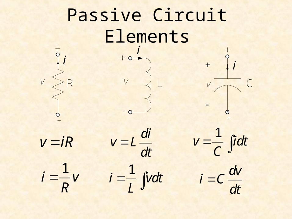
Passive Circuit Elements
v iR
1i v
R
div L
dt
1i vdt
L
1v idt
C
dvi C
dt
+
-
Rv
+
-
Lv
+
-
Cv
ii
i+
-
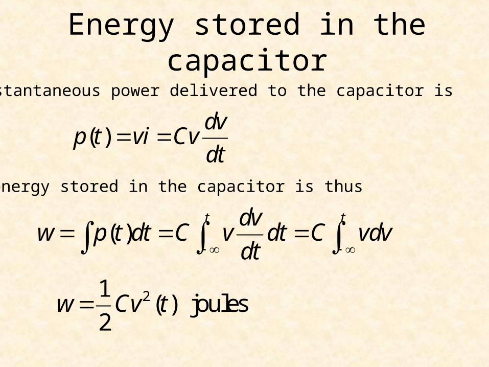
Energy stored in the capacitor
The instantaneous power delivered to the capacitor is
( )t tdv
w p t dt C v dt C vdvdt
( )dv
p t vi Cvdt
The energy stored in the capacitor is thus
21( ) joules
2w Cv t
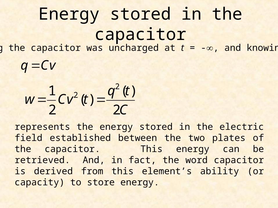
Energy stored in the capacitor
221 ( )( )
2 2
q tw Cv t
C
q CvAssuming the capacitor was uncharged at t = -, and knowing that
represents the energy stored in the electric field established between the two plates of the capacitor. This energy can be retrieved. And, in fact, the word capacitor is derived from this element’s ability (or capacity) to store energy.
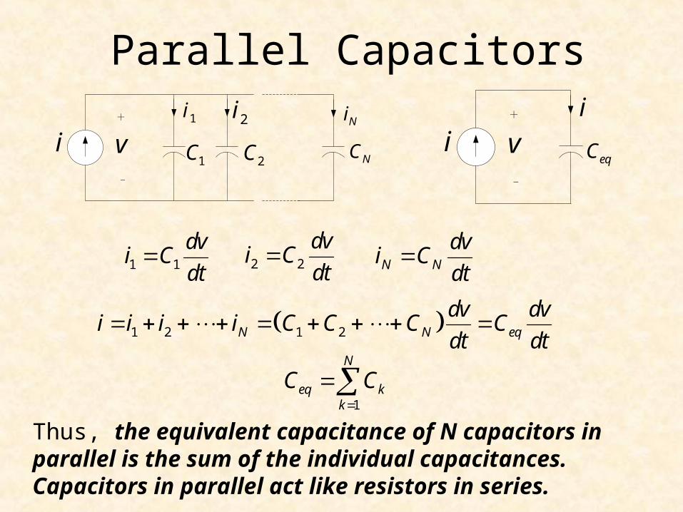
Parallel Capacitors
i1i 2i Ni
1C 2C NCv+
-
ii
eqCv+
-
1 1
dvi C
dt 2 2
dvi C
dt N N
dvi C
dt
1 2 1 2N N eq
dv dvi i i i C C C C
dt dt
1
N
eq kk
C C
Thus, the equivalent capacitance of N capacitors in parallel is the sum of the individual capacitances. Capacitors in parallel act like resistors in series.
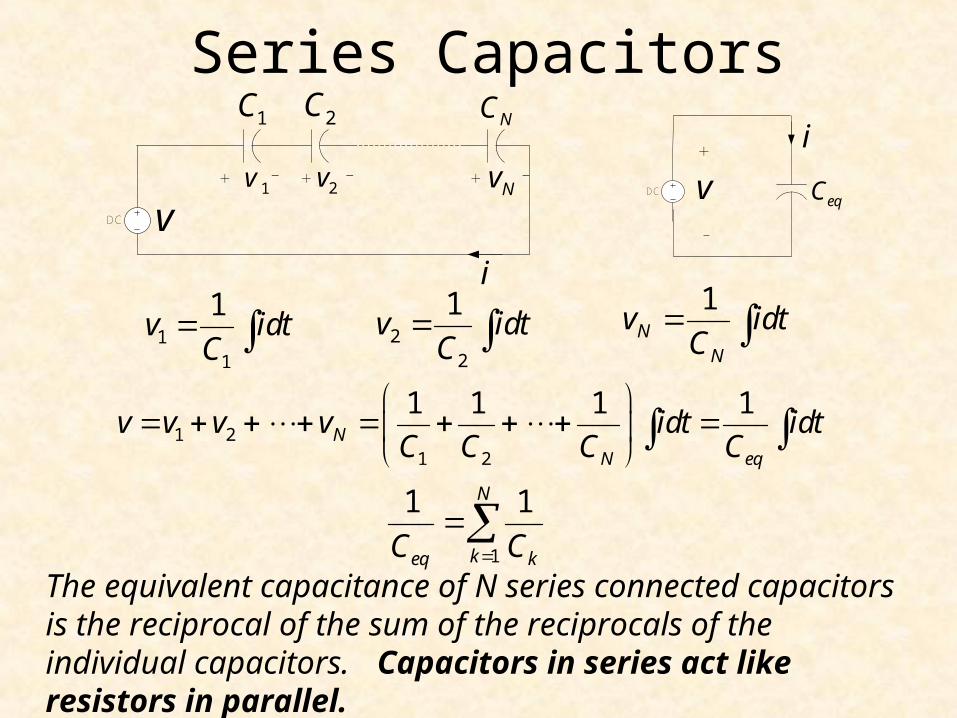
Series Capacitors
11
1v idt
C
1 21 2
1 1 1 1N
N eq
v v v v idt idtC C C C
1
1 1N
keq kC C
The equivalent capacitance of N series connected capacitors is the reciprocal of the sum of the reciprocals of the individual capacitors. Capacitors in series act like resistors in parallel.
DC
1v 2v Nv
1C 2C NC
vi
+ + + -- -
i
eqCv+
-
DC
22
1v idt
C
1N
N
v idtC
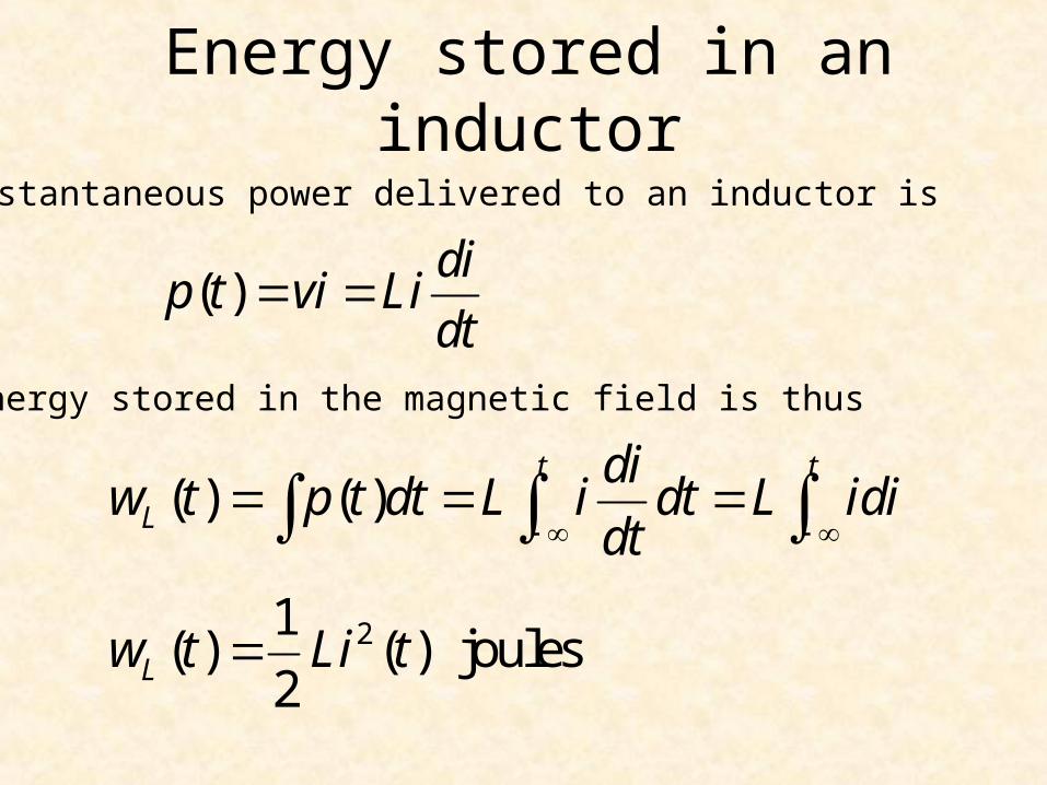
Energy stored in an inductor
The instantaneous power delivered to an inductor is
( ) ( )t t
L
diw t p t dt L i dt L idi
dt
( )di
p t vi Lidt
The energy stored in the magnetic field is thus
21( ) ( ) joules
2Lw t Li t
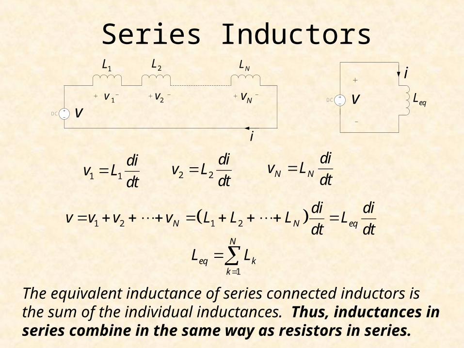
Series Inductors
1 1
div L
dt 2 2
div L
dt N N
div L
dt
1 2 1 2N N eq
di div v v v L L L L
dt dt
1
N
eq kk
L L
The equivalent inductance of series connected inductors is the sum of the individual inductances. Thus, inductances in series combine in the same way as resistors in series.
DC
1L 2L NL
1v 2v Nv+ + + -- -
v
i
i
eqLv+
-
DC
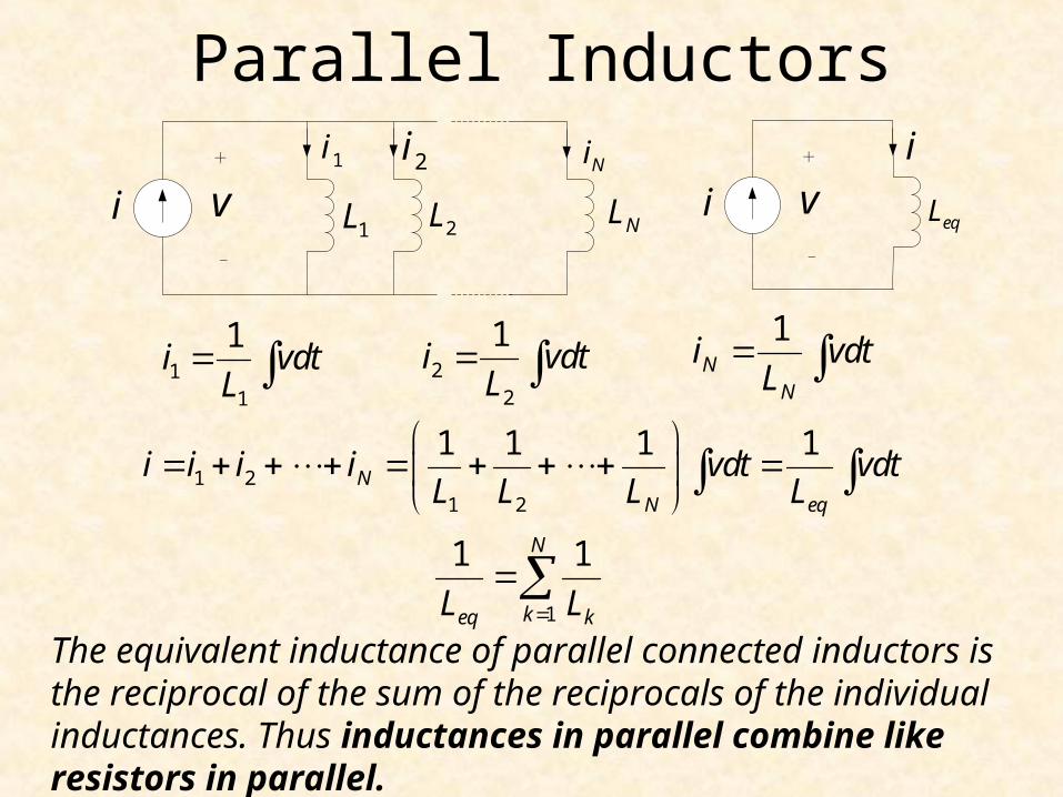
Parallel Inductors
11
1i vdt
L
1 21 2
1 1 1 1N
N eq
i i i i vdt vdtL L L L
1
1 1N
keq kL L
The equivalent inductance of parallel connected inductors is the reciprocal of the sum of the reciprocals of the individual inductances. Thus inductances in parallel combine like resistors in parallel.
22
1i vdt
L
1N
N
i vdtL
1i 2i Ni
1L 2L NLv+
-
i
i
v+
-
eqLi
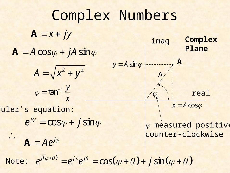
Complex Numbers
real
imag
A
x jy A
jAe A
1tany
x
cos sinje j Euler's equation:
cos sinA jA A
2 2A x y
cosx A
siny A
ComplexPlane
measured positivecounter-clockwise
cos sinj j je e e j
Note:
A
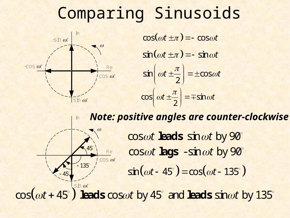
Comparing Sinusoids
sin 45 cos 135t t
sin cos2
t t
cos cost t
sin sint t
Note: positive angles are counter-clockwise
cos sin2
t t
cos sin by 90t t leads
cos - sin by 90t t lags
sin t
Re
Im
cos t
-sin t
-cos t
sin t
Re
Im
cos t
45
45
135
cos 45 cos by 45 and sin by 135t t t leads leads
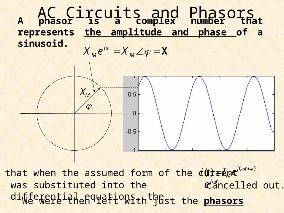
AC Circuits and Phasors
jM MX e X X
XM
Recall that when the assumed form of the current j te cancelled out.
We were then left with just the phasors
A phasor is a complex number that represents the amplitude and phase of a sinusoid.
( ) j tMi t I e
was substituted into the differential equations, the
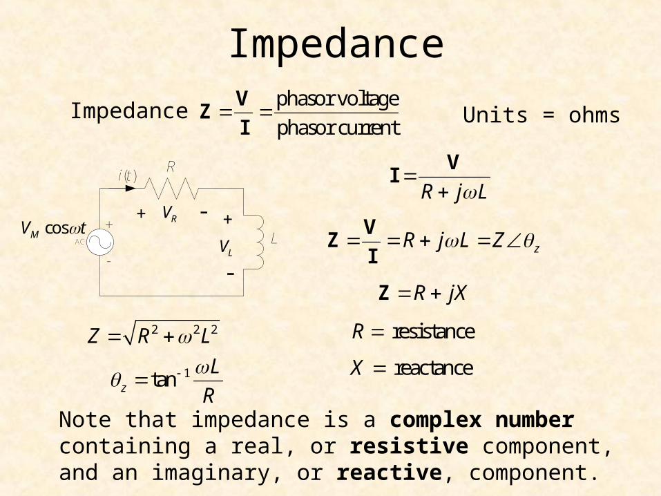
Impedance
Impedancephasor voltage
phasor current
VZ
I
2 2 2Z R L
R j L
V
I
zR j L Z V
ZI
1tanz
L
R
Note that impedance is a complex number containing a real, or resistive component, and an imaginary, or reactive, component.
Units = ohms
AC
R
LcosMV t
i(t)
+
-
VR
VL
+ -
-
+
R jX Z
resistanceR
reactanceX
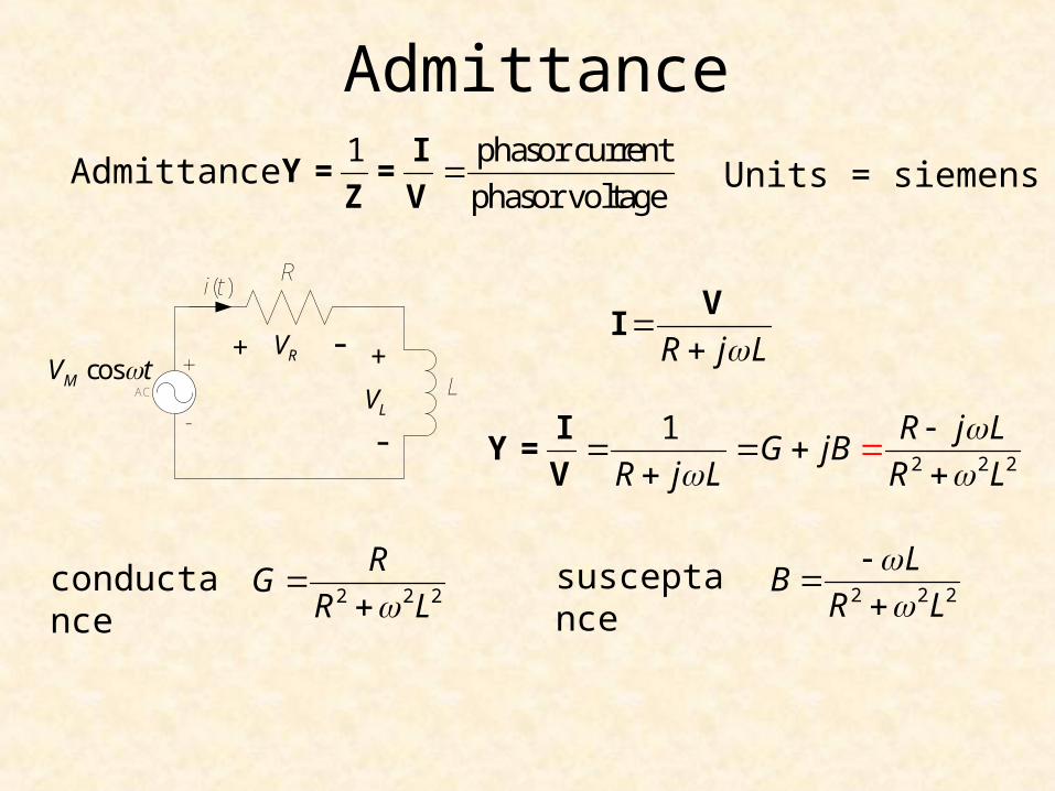
Admittance
Admittance1 phasor current
phasor voltage
IY = =
Z V
2 2 2
RG
R L
R j L
V
I
2 2 2
1 R j LG jB
R j L R L
I
Y =V
conductance
Units = siemens
susceptance2 2 2
LB
R L
AC
R
LcosMV t
i(t)
+
-
VR
VL
+ -
-
+
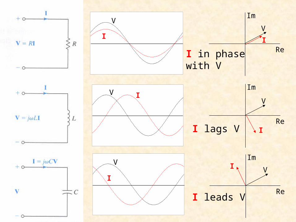
Re
Im
Re
Im
Re
Im
V
V
V
V
V
V
I
I
I
I
I
I
I in phasewith V
I lags V
I leads V
Z1
DC
Z2
Z3 Z4I1
I2V
I
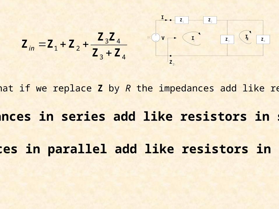
Zin
3 41 2
3 4in
Z Z
Z Z ZZ Z
We see that if we replace Z by R the impedances add like resistances.
Impedances in series add like resistors in series
Impedances in parallel add like resistors in parallel
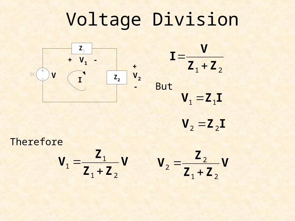
Voltage DivisionZ1
DCZ2
+
VI
V1
V2
+
-
-1 2
V
IZ Z
1 1V Z I
2 2V Z I
But
Therefore
11
1 2
Z
V VZ Z
22
1 2
Z
V VZ Z
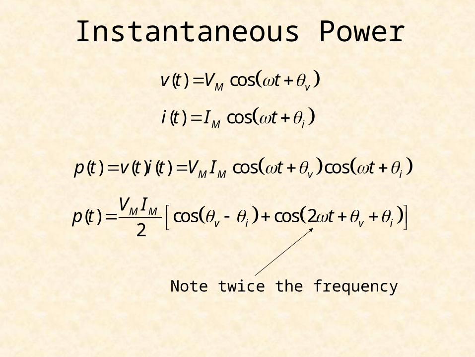
Instantaneous Power
( ) cosM vv t V t
( ) cosM ii t I t
( ) ( ) ( ) cos cosM M v ip t v t i t V I t t
( ) cos cos 22
M Mv i v i
V Ip t t
Note twice the frequency
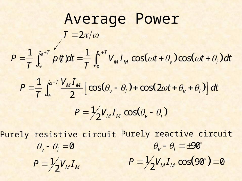
Average Power
0 0
0 0
1 1( ) cos cos
t T t T
M M v it tP p t dt V I t t dt
T T
0
0
1cos cos 2
2
t TM M
v i v it
V IP t dt
T
2T
1 cos2 M M v iP V I
0v i 90v i Purely resistive circuit Purely reactive circuit
12 M MP V I 1 cos 90 02 M MP V I

Effective or RMS ValuesWe define the effective or rms value of a periodic current (voltage) source to be the dc current (voltage) that delivers the same average power to a resistor.
0
0
2 21( )
t T
eff tP I R i t Rdt
T
0
0
21( )
t T
eff tI i t dt
T
eff rmsI I root-mean-square
0
0
2 21 ( )t Teff
t
V v tP dt
R T R
0
0
21( )
t T
eff tV v t dt
T
eff rmsV V
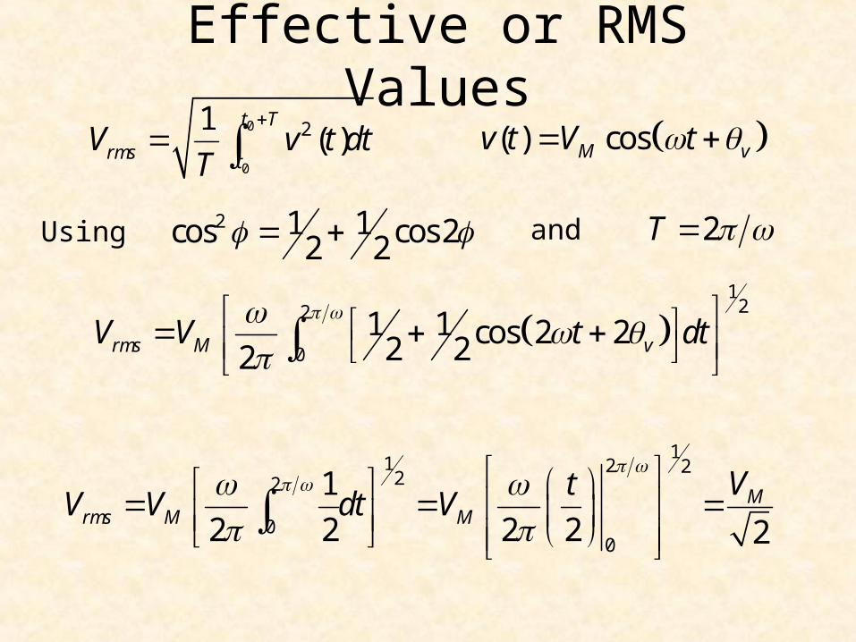
Effective or RMS Values
( ) cosM vv t V t
1
22
01 1 cos 2 22 22rms M vV V t dt
2 1 1cos cos 22 2 2T
0
0
21( )
t T
rms tV v t dt
T
11 2 2
22
00
1
2 2 2 2 2M
rms M M
VtV V dt V
Using and
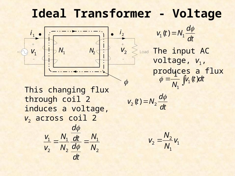
Ideal Transformer - Voltage
1 1( )d
v t Ndt
2 2( )d
v t Ndt
1 1 1
2 2 2
dv N Ndt
dv N Ndt
22 1
1
Nv v
N
11
1( )v t dt
N
The input AC voltage, v1, produces a flux
This changing flux through coil 2 induces a voltage, v2 across coil 2
1v 2v
2i1i
+ +
- -2N1NAC Load
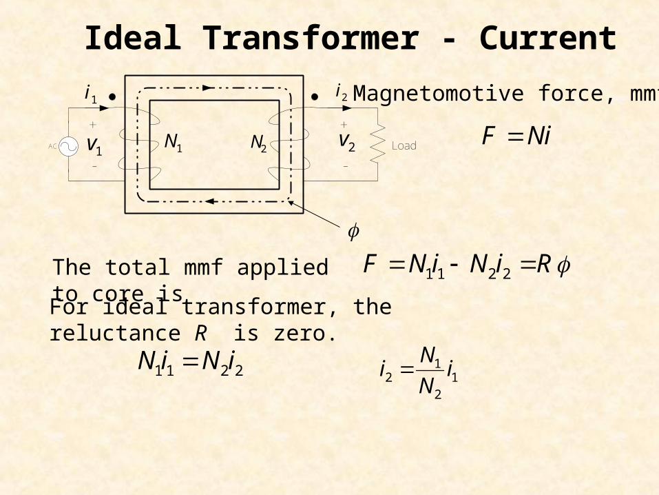
Ideal Transformer - Current
12 1
2
Ni i
N
The total mmf applied to core is
NiF
Magnetomotive force, mmf
1 1 2 2N i N i F R
For ideal transformer, the reluctance R is zero.
1 1 2 2N i N i
1v 2v
2i1i
+ +
- -2N1NAC Load
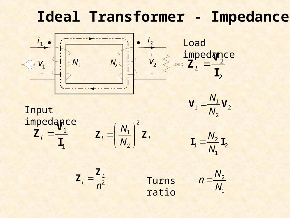
Ideal Transformer - Impedance
11 2
2
N
NV V
Input impedance
2
2L
VZ
I
21 2
1
N
NI I
1v 2v
2i1i
+ +
- -2N1NAC Load
Load impedance
1
1i
VZ
I
2
1
2i L
N
N
Z Z
2L
i n
ZZ 2
1
Nn
NTurns ratio
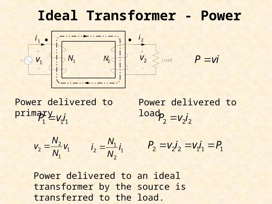
Ideal Transformer - Power
12 1
2
Ni i
N
Power delivered to primary
P vi
22 1
1
Nv v
N
1 1 1P v i
1v 2v
2i1i
+ +
- -2N1NAC Load
Power delivered to load
2 2 2P v i
2 2 2 1 1 1P v i v i P
Power delivered to an ideal transformer by the source is transferred to the load.
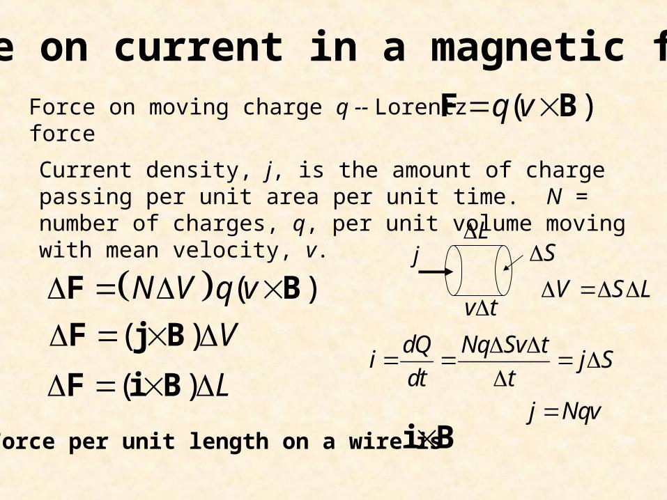
Force on current in a magnetic field( )q v F BForce on moving charge q -- Lorentz force
Current density, j, is the amount of charge passing per unit area per unit time. N = number of charges, q, per unit volume moving with mean velocity, v.
v t
Sj
j Nqv
( )N V q v F B
( ) V F j B
L
dQ Nq Sv ti j S
dt t
V S L
( ) L F i B
i BForce per unit length on a wire is
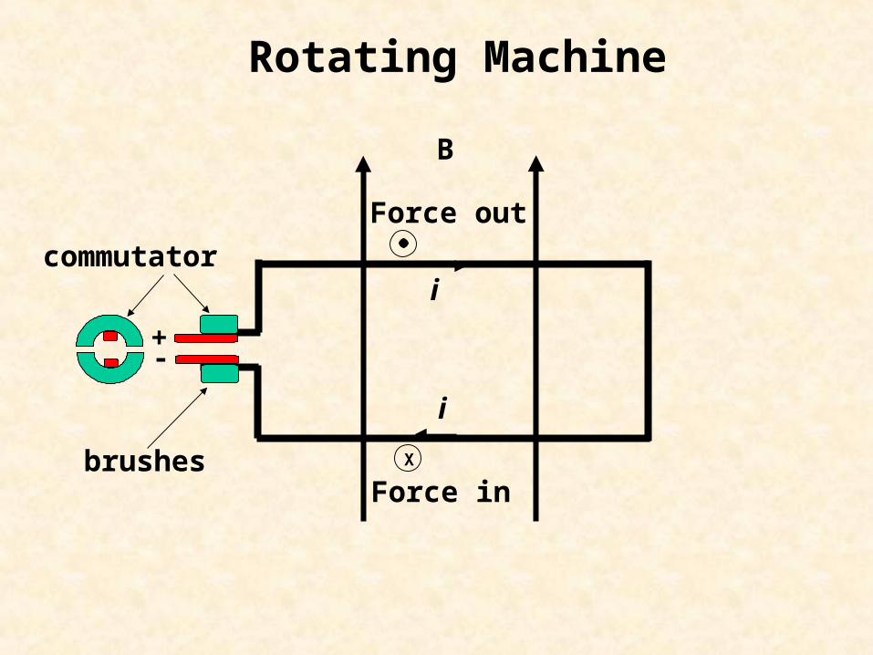
Rotating Machine
B
i
i
X
Force in
Force out
+-
brushes
commutator
B
i
iX
Force in
Force out
+-
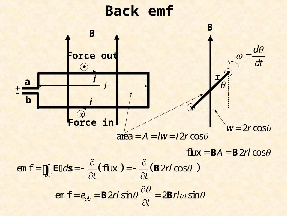
X
r
B
2 cosw r
flux 2 cosA rl B Β
area 2 cosA lw l r
l
d
dt
emf flux 2 cos d rlt t
E s B
emf 2 sin 2 sinabe rl rlt
B B
a
b
Back emf
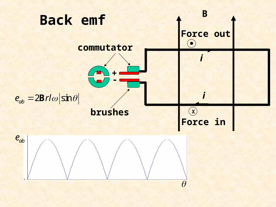
2 sinabe rl B
Back emf
abe
B
i
i
X
Force in
Force out
+-
brushes
commutator
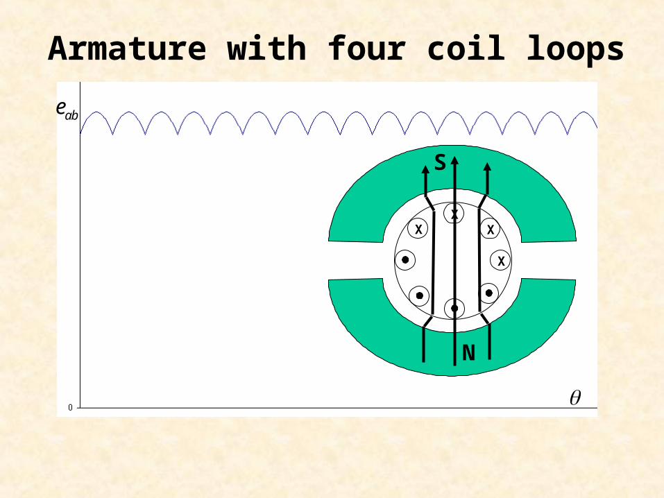
Armature with four coil loops
XXX
X
abe
N
S
aE
aR
tV
aI
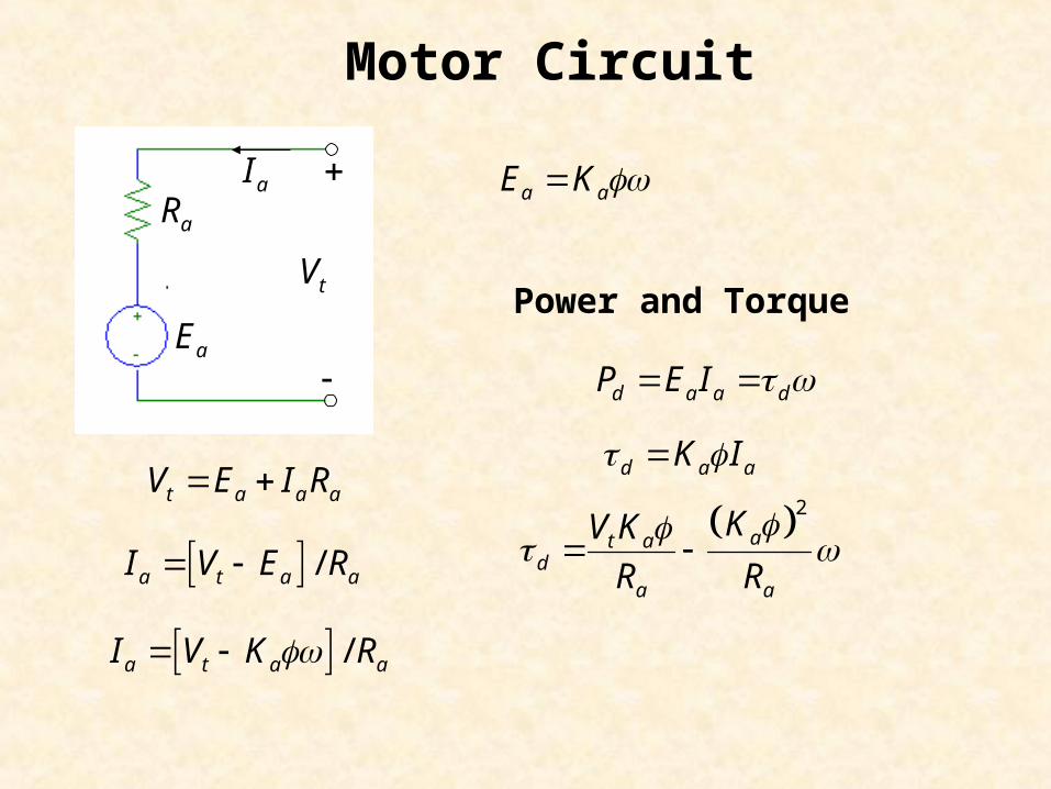
Motor Circuit
t a a aV E I R
a aE K
Power and Torque
d a a dP E I
/a t a aI V E R
d a aK I
/a t a aI V K R
2at ad
a a
KV K
R R

AC Nodal Analysis
For steady-state AC circuits we can use same the method of writing nodal equations by inspection that we learned for resistive circuits. To do so, we must replace resistances with impedances.
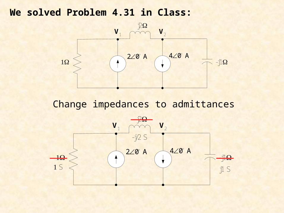
We solved Problem 4.31 in Class:
-j1
j2
2 0 A 4 0 A
V1 V2
Change impedances to admittances
-j1
j2
2 0 A 4 0 A
V1 V2
j1 SS
-j/2 S
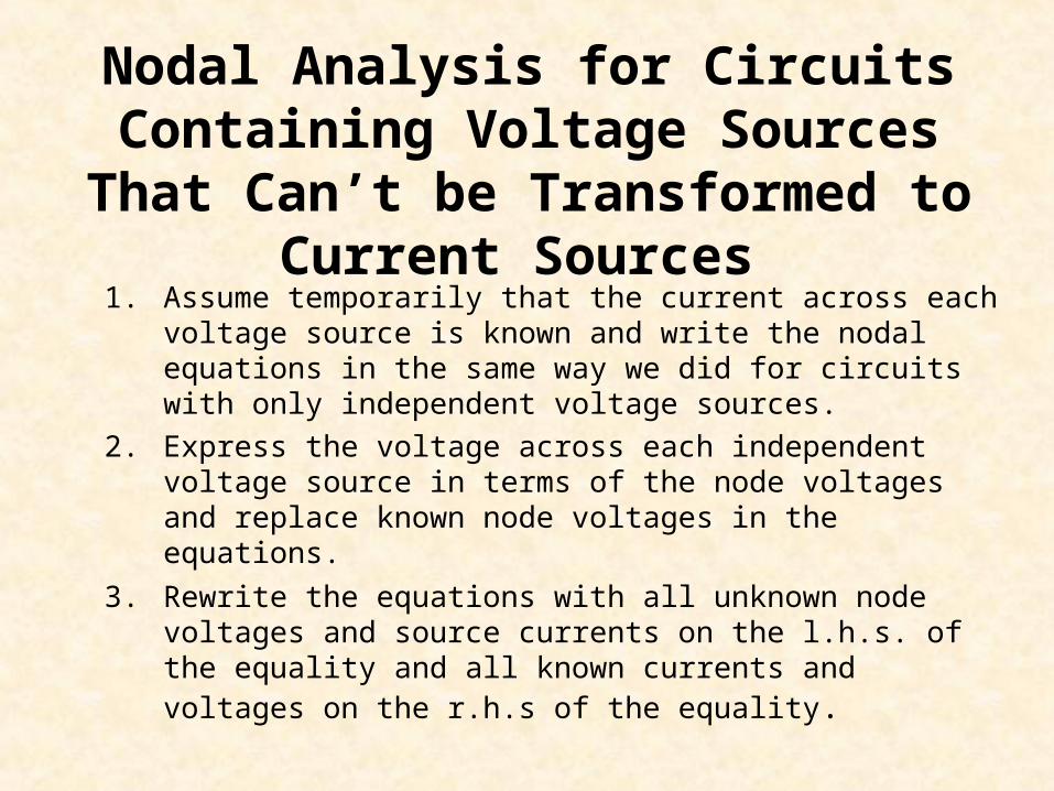
Nodal Analysis for Circuits Containing Voltage Sources That Can’t be
Transformed to Current Sources
1. Assume temporarily that the current across each voltage source is known and write the nodal equations in the same way we did for circuits with only independent voltage sources.
2. Express the voltage across each independent voltage source in terms of the node voltages and replace known node voltages in the equations.
3. Rewrite the equations with all unknown node voltages and source currents on the l.h.s. of the equality and all known currents and voltages on the r.h.s of the equality.

We solved #4.33 in text in Class: Note: V2 = 10
assume I2
-j4
j26 45 A 10 0 V
V1 V2
AC
+
-I0 I2
-j/2 S
j/4 S
1/2 S
1
2
0.5 0.25 0 4.243 6.743
0.25 1 2.5
j j
j j
V
I

AC Mesh Analysis

For steady-state AC circuits we can use same the method of writing mesh equations by inspection that we learned for resistive circuits. To do so, we must replace conductances with admittances.
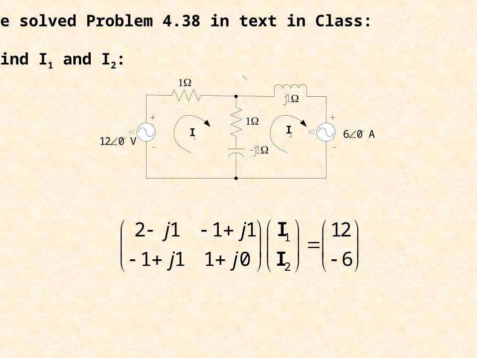
We solved Problem 4.38 in text in Class: Find I1 and I2:
6 0 A
12 0 V I1
I2AC AC
j1
-j1
+ +
- -
1
2
2 1 1 1 12
1 1 1 0 6
j j
j j
I
I
What happens if we have independent current sources that can’t be transformed in the circuit?
1. Assume temporarily that the voltage across each current source is known and write the mesh equations in the same way we did for circuits with only independent voltage sources.
2. Express the current of each independent current source in terms of the mesh currents and replace known mesh currents in the equations.
3. Rewrite the equations with all unknown mesh currents and voltages on the left hand side of the equality and all known voltages and currents on the r.h.s of the equality.
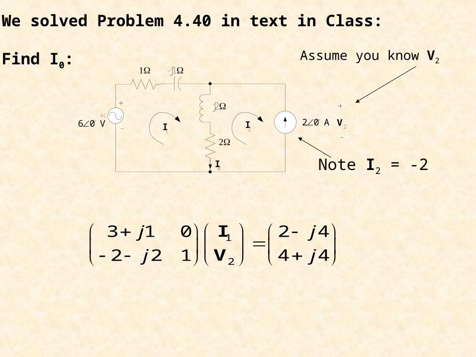
We solved Problem 4.40 in text in Class: Find I0:
2 0 A 6 0 V
I1I2
AC
-j1
+
-
j2
I0
V2
+
-
Assume you know V2
Note I2 = -2
1
2
3 1 0 2 4
2 2 1 4 4
j j
j j
I
V
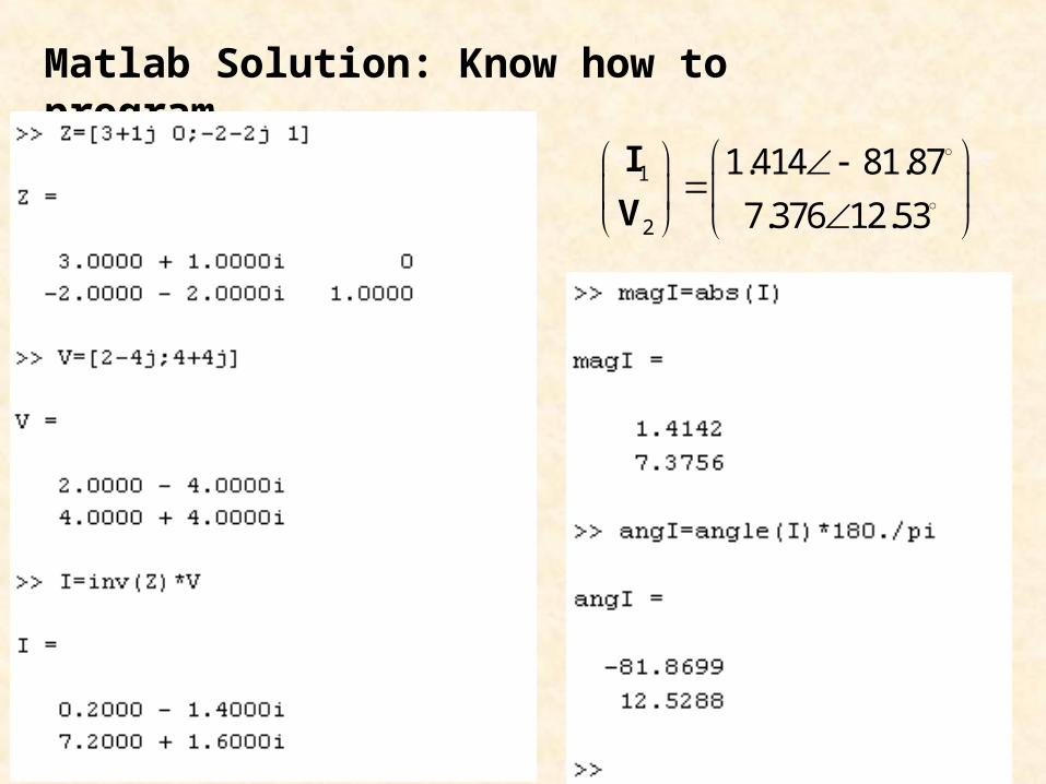
Matlab Solution: Know how to program
1
2
1.414 81.87
7.376 12.53
I
V
AC Thevenin's Theorem
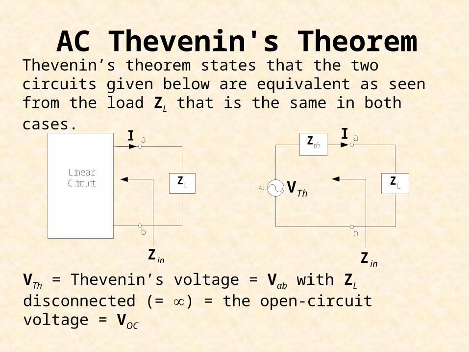
AC Thevenin's TheoremThevenin’s theorem states that the two circuits given below are equivalent as seen from the load ZL that is the same in both cases.
VTh = Thevenin’s voltage = Vab with ZL disconnected (= ) = the open-circuit voltage = VOC
LinearCircuit
b
a
inZ
I
ZL
b
a
ThVACZL
inZ
IZth
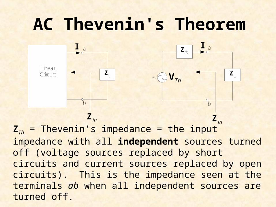
AC Thevenin's Theorem
ZTh = Thevenin’s impedance = the input impedance with all independent sources turned off (voltage sources replaced by short circuits and current sources replaced by open circuits). This is the impedance seen at the terminals ab when all independent sources are turned off.
LinearCircuit
b
a
inZ
I
ZL
b
a
ThVACZL
inZ
IZth
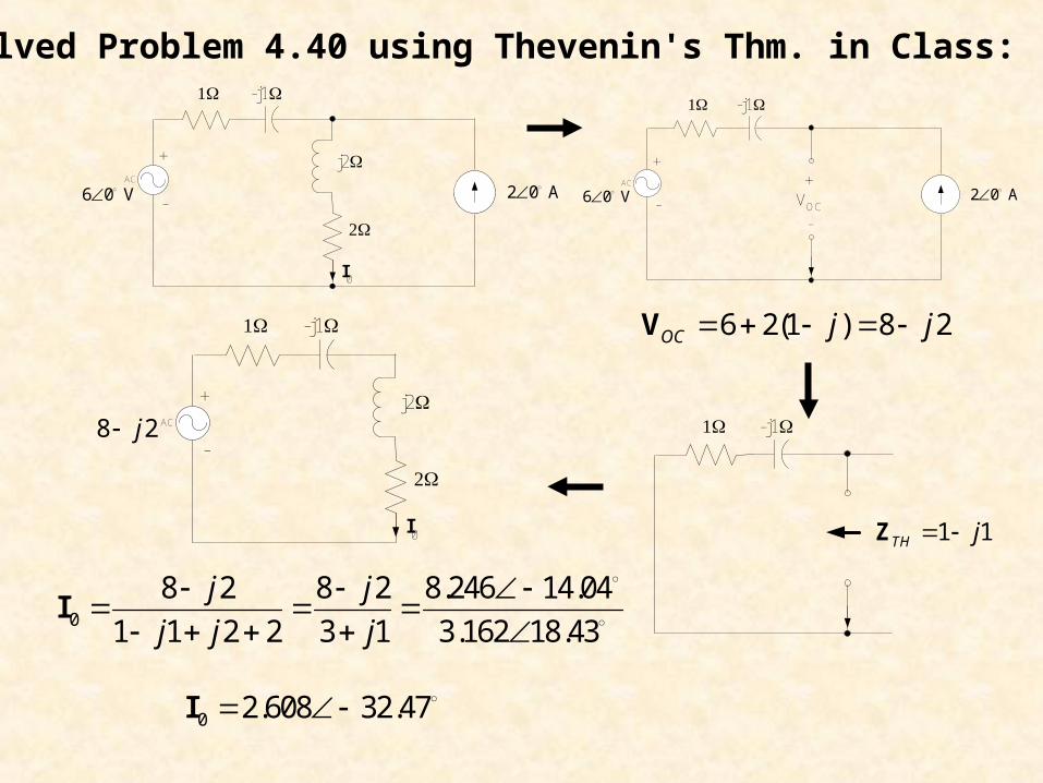
We solved Problem 4.40 using Thevenin's Thm. in Class:
0
8 2 8 2 8.246 14.04
1 1 2 2 3 1 3.162 18.43
j j
j j j
I
6 2(1 ) 8 2OC j j V
2 0 A 6 0 V
AC
-j1
+
-
j2
I0
2 0 A 6 0 V
AC
-j1
+
- VOC
+
-
-j1
1 1TH j Z
8 2j AC
-j1
+
-
j2
I0
0 2.608 32.47 I
AC Superposition
Superposition Principle
The superposition principle states that the voltage across (or the current through) an element in a linear circuit is the algebraic sum of the voltages across (or currents through) that element due to each independent source acting alone.
Steps in Applying the Superposition Principle
1. Turn off all independent sources except one. Find the output (voltage or current) due to the active source.
2. Repeat step 1 for each of the other independent sources.
3. Find the total output by adding algebraically all of the results found in steps 1 & 2 above.
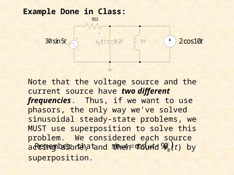
Example Done in Class:
Note that the voltage source and the current source have two different frequencies. Thus, if we want to use phasors, the only way we've solved sinusoidal steady-state problems, we MUST use superposition to solve this problem. We considered each source acting alone, and then found v0(t) by superposition.
sin cos 90t t Remember that
+
-AC
0.2F 1H 2cos10t30sin 5t+
-
v0(t)
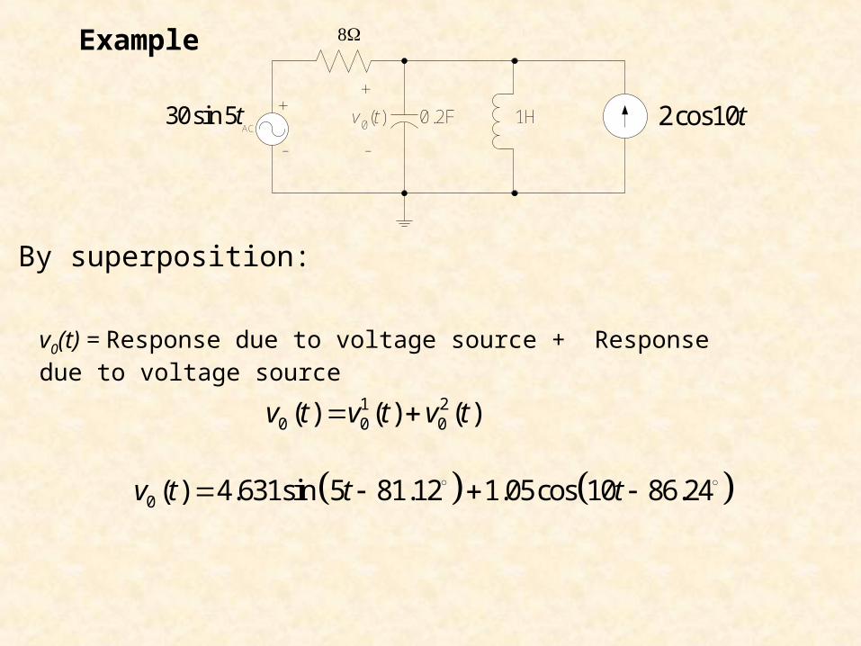
By superposition:
Example
+
-AC
0.2F 1H 2cos10t30sin 5t+
-
v0(t)
1 20 0 0( ) ( ) ( )v t v t v t
0 ( ) 4.631sin 5 81.12 1.05cos 10 86.24v t t t
v0(t) = Response due to voltage source + Response due to voltage source
Related Documents