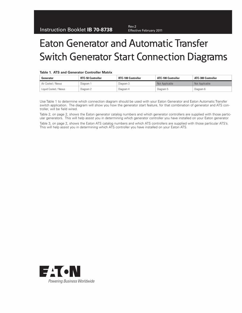
Rev.2 Effective February 2011 Instruction Booklet IB 70-8738 Eaton Generator and Automatic Transfer Switch Generator Start Connection Diagrams Table 1. ATS and Generator Controller Matrix Generator RTC-50 Controller RTC-100 Controller ATC-100 Controller ATC-300 Controller Air Cooled / Nexus Diagram 1 Diagram 3 Not Applicable Not Applicable Liquid Cooled / Nexus Diagram 2 Diagram 4 Diagram 5 Diagram 6 Use Table 1 to determine which connection diagram should be used with your Eaton Generator and Eaton Automatic Transfer switch application. The diagram will show you how the generator start feature, for that combination of generator and ATS con- troller, will be field wired. Table 2, on page 2, shows the Eaton generator catalog numbers and which generator controllers are supplied with those partic- ular generators. This will help assist you in determining which generator controller you have installed on your Eaton generator Table 3, on page 2, shows the Eaton ATS catalog numbers and which ATS controllers are supplied with those particular ATS’s. This will help assist you in determining which ATS controller you have installed on your Eaton ATS.

Welcome message from author
This document is posted to help you gain knowledge. Please leave a comment to let me know what you think about it! Share it to your friends and learn new things together.
Transcript
Rev.2Effective February 2011Instruction Booklet IB 70-8738
Eaton Generator and Automatic TransferSwitch Generator Start Connection Diagrams
Table 1. ATS and Generator Controller Matrix
Generator RTC-50 Controller RTC-100 Controller ATC-100 Controller ATC-300 Controller
Air Cooled / Nexus Diagram 1 Diagram 3 Not Applicable Not Applicable
Liquid Cooled / Nexus Diagram 2 Diagram 4 Diagram 5 Diagram 6
Use Table 1 to determine which connection diagram should be used with your Eaton Generator and Eaton Automatic Transfer switch application. The diagram will show you how the generator start feature, for that combination of generator and ATS con-troller, will be field wired.
Table 2, on page 2, shows the Eaton generator catalog numbers and which generator controllers are supplied with those partic-ular generators. This will help assist you in determining which generator controller you have installed on your Eaton generator
Table 3, on page 2, shows the Eaton ATS catalog numbers and which ATS controllers are supplied with those particular ATS’s. This will help assist you in determining which ATS controller you have installed on your Eaton ATS.
2
Instruction Booklet IB 70-8738Effective February 2011
Eaton Generator and Automatic TransferSwitch Generator Start Connection Diagrams
eaton corporation www.eaton.com
Table 2. Generator Controllers and Generator Catalog Numbers
Generators Associated with Each Generator Controller
Air Cooled Controller / Nexus Liquid Cooled / Nexus Liquid Cooled / Nexus
EGEN8 EGEN22 EGEN70
EGEN10 EGEN25 EGEN80
EGEN14 EGEN27 EGEN100
EGEN17 EGEN36 EGEN130
EGEN17A EGEN45 EGEN150
EGEN20A EGEN48
EGEN60
Table 3. ATS’s and ATS Catalog Numbers
ATS’s Associated with each ATS Controller
RTC-50 RTC-100 ATC-100 ATC-300
EGS50L12 EGSU100AC 69C2562G01 69C2562G11 69C2563G06
EGS50L12R EGSU100NSEAC 69C2562G02 69C2562G12 69C2563G07
EGS100 EGSU100L24RAC 69C2562G03 69C2562G13 69C2563G08
EGS100SE EGSU150NSEAC 69C2562G04 69C2562G14 69C2563G09
EGS100L24R EGSU200AC 69C2562G05 69C2562G50 69C2563G10
EGS200 EGSU200NSEAC 69C2562G06 69C2562G51 69C2563G11
EGS200SE EGSU400NSEAC 69C2562G09 69C2562G52 69C2563G12
EGS400NSE EGSU100ACA 69C2562G10 69C2562G53 69C2563G13
EGS100A EGSU100NSEACA 69C2563G01 69C2563G14
EGS100SEA EGSU100L24RACA 69C2563G02 69C2563G50
EGS100L24RA EGS150NSEACA 69C2563G03 69C2563G51
EGS200A EGSU200ACA 69C2563G04 69C2563G52
EGS200SEA EGSU200NSEACA 69C2563G05 69C2563G53
3
Instruction Booklet IB 70-8738Effective February 2011
Eaton Generator and Automatic TransferSwitch Generator Start Connection Diagrams
eaton corporation www.eaton.com
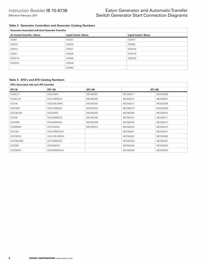
Figure 1. Connection of EATON RTC-50 ATS Controller to Utility Sensing on EATON Air Cooled Generator with Nexus Controler.
Connection of EATON RTC-50 ATS Controller to Utility Sensing on EATON Air Cooled Generator with Nexus Controller
N1
N2RTC-50 VIEW
MOUNTED ON GENERATOR
CONTROL PANEL
UTILITY 240 VAC
FUSE BLOCK IN ATS
Diagram 1
T1
T1
4
Instruction Booklet IB 70-8738Effective February 2011
Eaton Generator and Automatic TransferSwitch Generator Start Connection Diagrams
eaton corporation www.eaton.com
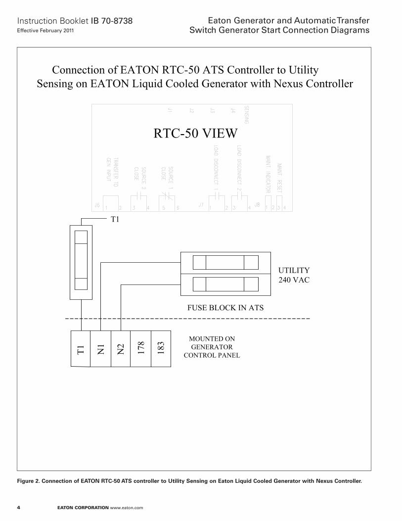
Figure 2. Connection of EATON RTC-50 ATS controller to Utility Sensing on Eaton Liquid Cooled Generator with Nexus Controller.
Connection of EATON RTC-50 ATS Controller to Utility Sensing on EATON Liquid Cooled Generator with Nexus Controller
N1
N2
RTC-50 VIEW
MOUNTED ON GENERATOR
CONTROL PANEL
UTILITY 240 VAC
FUSE BLOCK IN ATS
Diagram 2
178
183
T1
T1
5
Instruction Booklet IB 70-8738Effective February 2011
Eaton Generator and Automatic TransferSwitch Generator Start Connection Diagrams
eaton corporation www.eaton.com
Figure 3. Connection of EATON RTC-100 ATS Controller to Utility Sensing on EATON Air Cooled Generator with Nexus Controller.
Connection of EATON RTC-100 ATS Controller to Utility Sensing on EATON Air Cooled Generator
N1
N2
RTC-100 VIEW
MOUNTED ON GENERATOR CONTROL PANEL
UTILITY 240 VAC
FUSE BLOCK IN ATS
Diagram 3
T1
T1
6
Instruction Booklet IB 70-8738Effective February 2011
Eaton Generator and Automatic TransferSwitch Generator Start Connection Diagrams
eaton corporation www.eaton.com
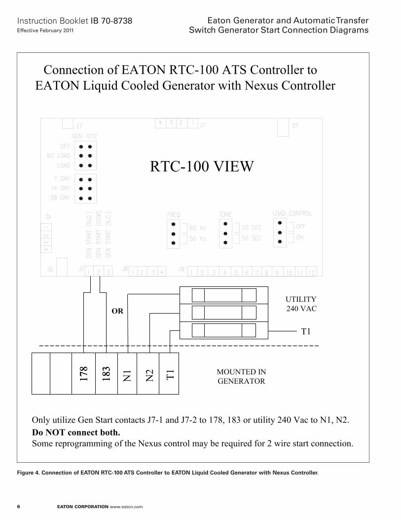
Figure 4. Connection of EATON RTC-100 ATS Controller to EATON Liquid Cooled Generator with Nexus Controller.
Connection of EATON RTC-100 ATS Controller to EATON Liquid Cooled Generator with Nexus Controller
178
183
178
183
178
183
Only utilize Gen Start contacts J7-1 and J7-2 to 178, 183 or utility 240 Vac to N1, N2. Do NOT connect both. Some reprogramming of the Nexus control may be required for 2 wire start connection.
RTC-100 VIEW
MOUNTED IN GENERATOR
Diagram 4
UTILITY 240 VAC
N1
N2
OR
T1
T1
7
Instruction Booklet IB 70-8738Effective February 2011
Eaton Generator and Automatic TransferSwitch Generator Start Connection Diagrams
eaton corporation www.eaton.com
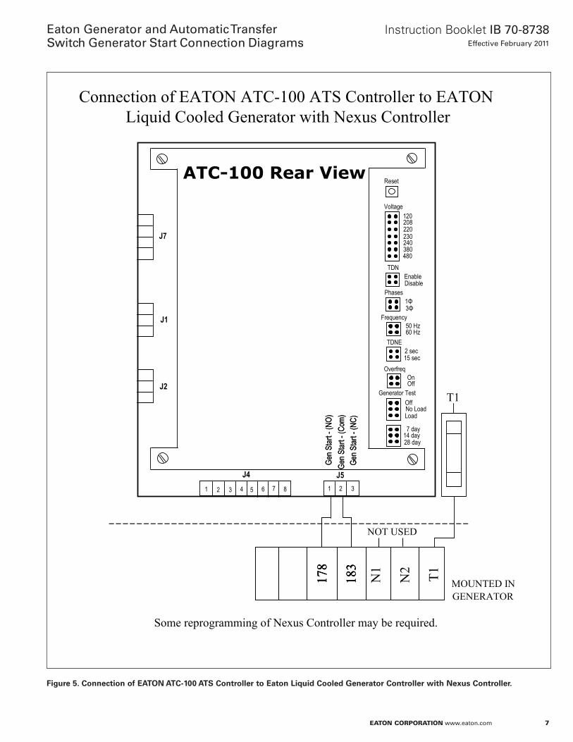
Figure 5. Connection of EATON ATC-100 ATS Controller to Eaton Liquid Cooled Generator Controller with Nexus Controller.
1 2 3 4 5 6 7 8 1 2
J4
J7
J2
J1
J53
Gen S
tart -
(Com
)Ge
n Star
t -(N
O)
Gen S
tart -
(NC)
Gen S
tart -
(Com
)Ge
n Star
t -(N
O)
Gen S
tart -
(NC)
Reset
120208220230240380480
Voltage
1Φ3Φ
Phases
50 Hz60 Hz
Frequency
2 sec15 sec
TDNE
OnOff
Overfreq
OffNo LoadLoad
Generator Test
7 day14 day28 day
EnableDisable
TDN
Connection of EATON ATC-100 ATS Controller to EATON Liquid Cooled Generator with Nexus Controller
ATC-100 Rear View
178
183
178
183
178
183
Some reprogramming of Nexus Controller may be required.
MOUNTED IN GENERATOR
T1
T1
N1
N2
NOT USED
8
Instruction Booklet IB 70-8738Effective February 2011
Eaton Generator and Automatic TransferSwitch Generator Start Connection Diagrams
eaton corporation www.eaton.com
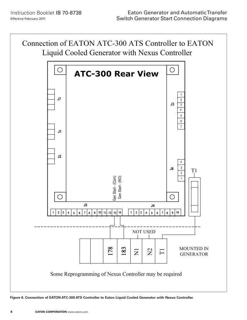
Figure 6. Connection of EATON ATC-300 ATS Controller to Eaton Liquid Cooled Generator with Nexus Controller.
1 2 3 4 5 6 7 8 9 10 11 12 13 141 2 3 4 5 6 7 8 9 10 11 12 13 14 1 2 3 4 5 6 7 8 9 101 2 3 4 5 6 7 8 9 10
J5
J7
J2
J1
J4
1234
5
J3
ATC-300 Rear View
Gen S
tart -
(Com
)Ge
n Star
t -(N
O)6
7
1
23
4
J8
178
183
178
183
178
183
Some Reprogramming of Nexus Controller may be required
Connection of EATON ATC-300 ATS Controller to EATONLiquid Cooled Generator with Nexus Controller
MOUNTED IN GENERATOR
Diagram 8
N1
N2
NOT USED
T1T1
9
Instruction Booklet IB 70-8738Effective February 2011
Eaton Generator and Automatic TransferSwitch Generator Start Connection Diagrams
eaton corporation www.eaton.com
Notes:
10
Instruction Booklet IB 70-8738Effective February 2011
Eaton Generator and Automatic TransferSwitch Generator Start Connection Diagrams
eaton corporation www.eaton.com
Notes:

11
Instruction Booklet IB 70-8738Effective February 2011
Eaton Generator and Automatic TransferSwitch Generator Start Connection Diagrams
eaton corporation www.eaton.com
Notes:
Instruction Booklet IB 70-8738Effective February 2011
Eaton Generator and Automatic TransferSwitch Generator Start Connection Diagrams
Eaton CorporationElectrical Group1000 Cherrington ParkwayMoon Township, PA 15108United States877-ETN-CARE (877-386-2273)Eaton.com
© 2010 Eaton CorporationAll Rights ReservedPrinted in USAPublication No. IB 70-8738 / TBG000556February 2011
PowerChain Management is a registered trademark of Eaton Corporation.
All other trademarks are property of their respective owners.
This instruction booklet is published solely for information purposes and should not be considered all-inclusive. If further information is required, you should consult Eaton.
Sale of product shown in this literature is subject to terms and con-ditions outlined in appropriate Eaton selling policies or other contrac-tual agreement between the parties. This literature is not intended to and does not enlarge or add to any such contract. The sole source governing the rights and remedies of any purchaser of this equipment is the contract between the purchaser and Eaton.
NO WARRANTIES, EXPRESSED OR IMPLIED, INCLUDING WARRANTIES OF FITNESS FOR A PARTICULAR PURPOSE OR MERCHANTABILITY, OR WARRANTIES ARISING FROM COURSE OF DEALING OR USAGE OF TRADE, ARE MADE REGARDING THE INFORMATION, RECOMMENDATIONS AND DESCRIPTIONS CONTAINED HEREIN. In no event will Eaton be responsible to the purchaser or user in contract, in tort (including negligence), strict liability or otherwise for any special, indirect, incidental or conse-quential damage or loss whatsoever, including but not limited to damage or loss of use of equipment, plant or power system, cost of capital, loss of power, additional expenses in the use of existing power facilities, or claims against the purchaser or user by its cus-tomers resulting from the use of the information, recommendations and description contained herein.
OJ4362
Related Documents