Copyright © 2013 by ELENCO ® Electronics, Inc. All rights reserved. No part of this book shall be reproduced by 753154 any means; electronic, photocopying, or otherwise without written permission from the publisher. REV-A Patent #‘s: 7,144,255, 7,273,377, & other patents pending Project A3

Welcome message from author
This document is posted to help you gain knowledge. Please leave a comment to let me know what you think about it! Share it to your friends and learn new things together.
Transcript
Copyright © 2013 by ELENCO® Electronics, Inc. All rights reserved. No part of this book shall be reproduced by 753154any means; electronic, photocopying, or otherwise without written permission from the publisher.
REV-APatent #‘s: 7,144,255, 7,273,377, & other patents pending
Project A3
-1-
WARNING: SHOCK HAZARD - Never connect SnapCircuits® to the electrical outlets in your home in any way!
WARNING: CHOKING HAZARD - Smallparts. Not for children under 3 years.!
Conforms to allapplicable U. S.
government standards.
1. Most circuit problems are due to incorrectassembly, always double-check that yourcircuit exactly matches the drawing for it.
2. Be sure that parts with positive/negativemarkings are positioned as per the drawing.
3. Be sure that all connections are securelysnapped.
4. Try replacing the batteries.5. If the motor spins but does not balance the
fan, check the black plastic piece with threeprongs on the motor shaft.
ELENCO® is not responsible for parts damageddue to incorrect wiring.
Basic Troubleshooting
Note: If you suspect you have damaged parts, youcan follow the Advanced Troubleshooting procedure onpage 8 to determine which ones need replacing.
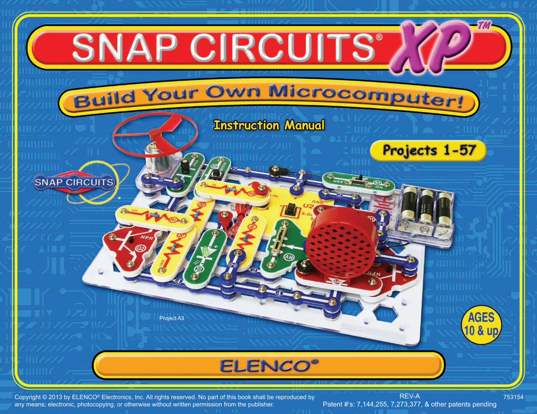
Basic Troubleshooting 1Parts List 2About Your Snap Circuits® Parts 3 - 5Introduction to Electricity 6DO’s and DON’Ts of Building Circuits 7Advanced Troubleshooting 8
Project Listings 9How to Use Snap Circuits® 10Part A – Introductory Projects (A1-A30) 11 - 27Part B – Microcontroller Projects (B1-B27) 28 - 58Part C – To Go Further 59Other Snap Circuits® Products 62
Table of Contents
WARNING: Always check your wiring beforeturning on a circuit. Never leave a circuitunattended while the batteries are installed.Never connect additional batteries or anyother power sources to your circuits. Discardany cracked or broken parts.Adult Supervision: Because children’sabilities vary so much, even with age groups,adults should exercise discretion as to whichexperiments are suitable and safe (theinstructions should enable supervisingadults to establish the experiment’s
suitability for the child). Make sure your childreads and follows all of the relevantinstructions and safety procedures, andkeeps them at hand for reference.This product is intended for use by adultsand children who have attained sufficientmaturity to read and follow directions andwarnings.Never modify your parts, as doing so maydisable important safety features in them, andcould put your child at risk of injury.
• Use only 1.5V “AA” type, alkaline batteries (notincluded).
• Insert batteries with correct polarity.• Non-rechargeable batteries should not be
recharged. Rechargeable batteries should onlybe charged under adult supervision, and shouldnot be recharged while in the product.
• Do not connect batteries or battery holders inparallel.
• Do not mix old and new batteries.• Do not mix alkaline, standard (carbon-zinc), or
rechargeable (nickel-cadmium) batteries.• Remove batteries when they are used up.• Do not short circuit the battery terminals.• Never throw batteries in a fire or attempt to open
its outer casing.• Batteries are harmful if swallowed, so keep away
from small children.
Batteries:!
WARNING TO ALL PROJECTS WITH A SYMBOL - Moving parts. Do not touch the motor or fan during operation. Do notlean over the motor. Do not launch the fan at people, animals, or objects. Eye protection is recommended.! !!
Requirements for your computer: Windows®XP (or later) or Mac OS X 10.2 (or later) or Linux,512MB RAM, 500MB of hard-disk space, USBport, and an internet connection.
-2-
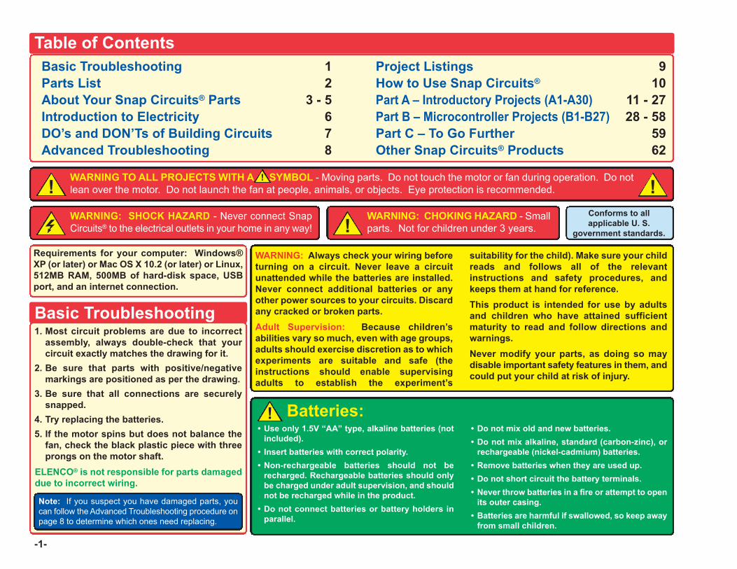
Important: If any parts are missing or damaged, DO NOT RETURN TO RETAILER. Call toll-free (800) 533-2441 or e-mail us at:[email protected]. Customer Service • 150 Carpenter Ave. • Wheeling, IL 60090 U.S.A.
Parts List (Colors and styles may vary) Symbols and Numbers
Qty. ID Name Symbol Part # Qty. ID Name Symbol Part #
r 1 Base Grid(11.0” x 7.7”) 6SCBG r 1 Fan Blade 6SCM1F
r 6 1-Snap Wire 6SC01 r 2 NPN Transistor 6SCQ2
r 9 2-Snap Wire 6SC02 r 1 100W Resistor 6SCR1
r 4 3-Snap Wire 6SC03 r 2 1kW Resistor 6SCR2
r 3 4-Snap Wire 6SC04 r 2 10kW Resistor 6SCR4
r 1 5-Snap Wire 6SC05 r 1 100kW Resistor 6SCR5
r 1 6-Snap Wire 6SC06 r 1 Photoresistor 6SCRP
r 1 7-Snap Wire 6SC07 r 1 Adjustable Resistor 6SCRV
r 1 Battery Holder - uses3 1.5V type AA (not Included) 6SCB3 r 1 Slide Switch 6SCS1
r 1 470mF Capacitor 6SCC5 r 1 Press Switch 6SCS2
r 1 Red Light EmittingDiode (LED) 6SCD1 r 1 8 Ohm Speaker 6SCSP
r 1 Green Light EmittingDiode (LED) 6SCD2 r 1 Microcontroller IC 6SCU21
r 1 Jumper Wire (Black) 6SCJ1 r 1 Microphone 6SCX1
r 1 Jumper Wire (Red) 6SCJ2 r 1 Programming Cable 9TLSCXP
r 1 DC Motor 6SCM1
You may order additional / replacement parts at our website: www.snapcircuits.net
5
4
3
2
1
RP
U21
S2
R2
X1
B3
D1
C5
D2
R1
SP
6
7
M1
Q2
R5
R4
RV
S1
-3-
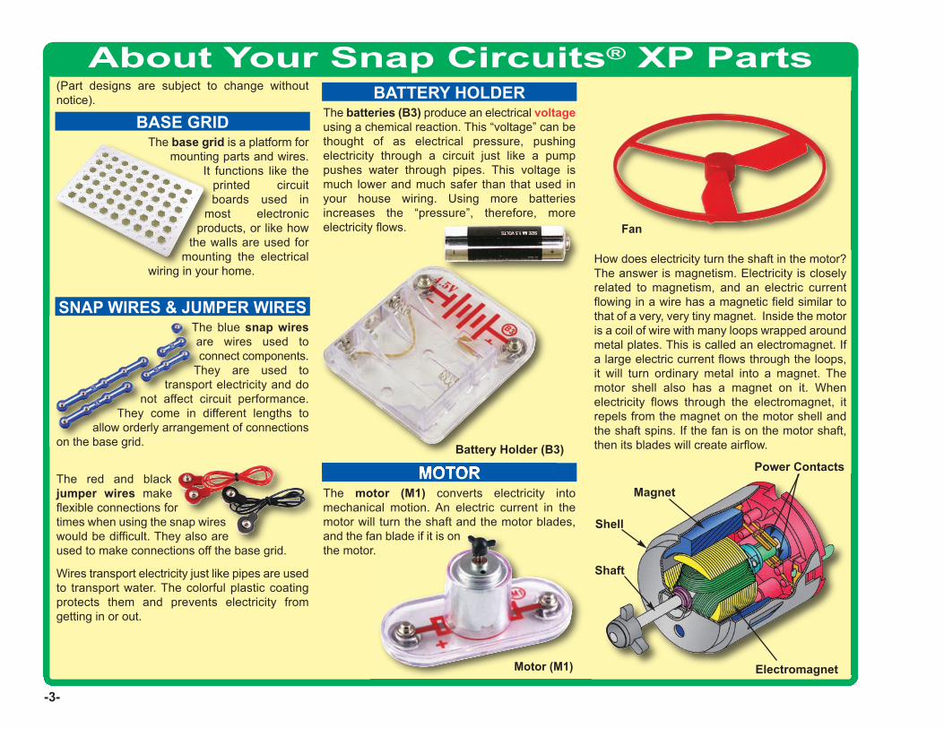
About Your Snap Circuits® XP Parts(Part designs are subject to change withoutnotice).
BASE GRID
SNAP WIRES & JUMPER WIRES
MOTORMagnet
Electromagnet
Shaft
Power Contacts
Shell
Motor (M1)
BATTERY HOLDER
Battery Holder (B3)
The batteries (B3) produce an electrical voltageusing a chemical reaction. This “voltage” can bethought of as electrical pressure, pushingelectricity through a circuit just like a pumppushes water through pipes. This voltage ismuch lower and much safer than that used inyour house wiring. Using more batteriesincreases the “pressure”, therefore, moreelectricity flows.
The blue snap wiresare wires used toconnect components.
They are used totransport electricity and do
not affect circuit performance.They come in different lengths to
allow orderly arrangement of connectionson the base grid.
The red and blackjumper wires makeflexible connections fortimes when using the snap wireswould be difficult. They also areused to make connections off the base grid.
Wires transport electricity just like pipes are usedto transport water. The colorful plastic coatingprotects them and prevents electricity fromgetting in or out.
The base grid is a platform formounting parts and wires.
It functions like theprinted circuitboards used in
most electronicproducts, or like how
the walls are used formounting the electrical
wiring in your home.
The motor (M1) converts electricity intomechanical motion. An electric current in themotor will turn the shaft and the motor blades,and the fan blade if it is onthe motor.
Fan
How does electricity turn the shaft in the motor?The answer is magnetism. Electricity is closelyrelated to magnetism, and an electric currentflowing in a wire has a magnetic field similar tothat of a very, very tiny magnet. Inside the motoris a coil of wire with many loops wrapped aroundmetal plates. This is called an electromagnet. Ifa large electric current flows through the loops,it will turn ordinary metal into a magnet. Themotor shell also has a magnet on it. Whenelectricity flows through the electromagnet, itrepels from the magnet on the motor shell andthe shaft spins. If the fan is on the motor shaft,then its blades will create airflow.

-4-
About Your Snap Circuits® XP PartsRESISTORS
MICROPHONE
SPEAKER
SLIDE & PRESS SWITCHES RED & GREEN LEDs
CAPACITOR
Resistors (R1, R2, R4, & R5)
Resistors “resist” the flow of electricity and areused to control or limit the current in a circuit.Snap Circuits® XP includes 100W (R1), 1kW (R2),10kW (R4), and 100kW(R5) resistors (“K”symbolizes 1,000, so R4 is really 10,000W).Materials like metal have very low resistance(<1W), while materials like paper, plastic, and airhave near-infinite resistance. Increasing circuitresistance reduces the flow of electricity.
The slide & press switches (S1 & S2) connect(pressed or “ON”) or disconnect (not pressed or“OFF”) the wires in a circuit. When ON they have noeffect on circuit performance. Switches turn onelectricity just like a faucet turns on water from a pipe.
Slide & Press Switches (S1 & S2)
The speaker (SP) converts electricity into soundby making mechanicalvibrations. These vibrationscreate variations in airpressure, which travelacross the room. You“hear” sound when yourears feel these airpressure variations.
Speaker (SP)
The microphone (X1) is actually a resistor thatchanges in value when changes in air pressure(sounds) apply pressure to its surface. Itsresistance typically varies from around 1kW insilence to around 10kW when you blow on it
Microphone (X1)
The photoresistor (RP) is a light-sensitiveresistor, its value changes from nearly infinite intotal darkness to about 1000W when a bright lightshines on it.
Photoresistor (RP)
The adjustable resistor (RV) is a 50kW resistorbut with a center tap that can be adjustedbetween 200W and 50kW.
Adjustable Resistor (RV)
The 470mF capacitor (C5) can store electricalpressure (voltage) for periods of time. Thisstorage ability allows it to block stable voltagesignals and pass changing ones. Capacitors areused for filtering and delay circuits.
Capacitor (C5)
The red & green LED’s (D1 & D2) are lightemitting diodes, and may be thought of as aspecial one-way light bulb. In the “forward”direction, (indicated by the “arrow” in the symbol)electricity flows if the voltage exceeds a turn-onthreshold (about 1.5V for red and a little higherfor green); brightness then increases. A highcurrent will burn out the LED, so the current mustbe limited by other components in the circuit.LED’s block electricity in the “reverse” direction.
LED’s (D1 & D2)
-5-
About Your Snap Circuits® XPTM Parts
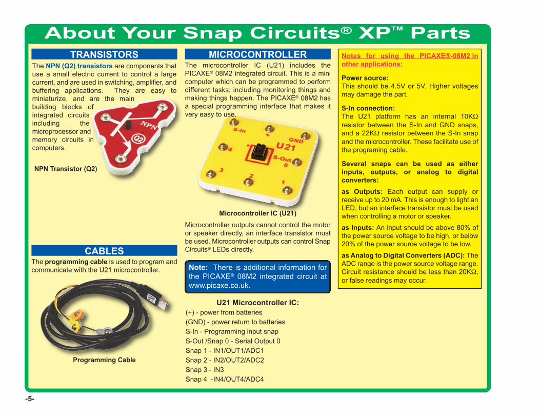
The NPN (Q2) transistors are components thatuse a small electric current to control a largecurrent, and are used in switching, amplifier, andbuffering applications. They are easy tominiaturize, and are the mainbuilding blocks ofintegrated circuitsincluding themicroprocessor andmemory circuits incomputers.
TRANSISTORS
U21 Microcontroller IC:(+) - power from batteries(GND) - power return to batteriesS-In - Programming input snapS-Out /Snap 0 - Serial Output 0Snap 1 - IN1/OUT1/ADC1Snap 2 - IN2/OUT2/ADC2Snap 3 - IN3Snap 4 -IN4/OUT4/ADC4
Note: There is additional information forthe PICAXE® 08M2 integrated circuit atwww.picaxe.co.uk.
The programming cable is used to program andcommunicate with the U21 microcontroller.
CABLES
MICROCONTROLLER
Microcontroller outputs cannot control the motoror speaker directly, an interface transistor mustbe used. Microcontroller outputs can control SnapCircuits® LEDs directly.
Programming Cable
NPN Transistor (Q2)
The microcontroller IC (U21) includes thePICAXE® 08M2 integrated circuit. This is a minicomputer which can be programmed to performdifferent tasks, including monitoring things andmaking things happen. The PICAXE® 08M2 hasa special programming interface that makes itvery easy to use.
Microcontroller IC (U21)
Notes for using the PICAXE®-08M2 inother applications:
Power source:This should be 4.5V or 5V. Higher voltagesmay damage the part.
S-In connection:The U21 platform has an internal 10KWresistor between the S-In and GND snaps,and a 22KW resistor between the S-In snapand the microcontroller. These facilitate use ofthe programing cable.
Several snaps can be used as eitherinputs, outputs, or analog to digitalconverters:as Outputs: Each output can supply orreceive up to 20 mA. This is enough to light anLED, but an interface transistor must be usedwhen controlling a motor or speaker.
as Inputs: An input should be above 80% ofthe power source voltage to be high, or below20% of the power source voltage to be low.
as Analog to Digital Converters (ADC): TheADC range is the power source voltage range.Circuit resistance should be less than 20KW,or false readings may occur.

Introduction to ElectricityWhat is electricity? Nobody really knows. We only know how to produce it,understand its properties, and how to control it. Electricity is the movementof sub-atomic charged particles (called electrons) through a material dueto electrical pressure across the material, such as from a battery. Power sources, such as batteries, push electricity through a circuit, like apump pushes water through pipes. Wires carry electricity, like pipes carrywater. Devices like LEDs, motors, and speakers use the energy inelectricity to do things. Switches and transistors control the flow ofelectricity like valves and faucets control water. Resistors limit the flow ofelectricity. The electrical pressure exerted by a battery or other power source is calledvoltage and is measured in volts (V). Notice the “+” and “–” signs on thebattery; these indicate which direction the battery will “pump” the electricity. The electric current is a measure of how fast electricity is flowing in awire, just as the water current describes how fast water is flowing in a pipe.It is expressed in amperes (A) or milliamps (mA, 1/1000 of an ampere).The “power” of electricity is a measure of how fast energy is movingthrough a wire. It is a combination of the voltage and current (Power =Voltage x Current). It is expressed in watts (W). The resistance of a component or circuit represents how much it resiststhe electrical pressure (voltage) and limits the flow of electric current. Therelationship is Voltage = Current x Resistance. When the resistanceincreases, less current flows. Resistance is measured in ohms (W), or kiloohms (kW, 1000 ohms).
Nearly all of the electricity used in our world is produced at enormousgenerators driven by steam or water pressure. Wires are used to efficientlytransport this energy to homes and businesses where it is used. Motorsconvert the electricity back into mechanical form to drive machinery andappliances. The most important aspect of electricity in our society is that itallows energy to be easily transported over distances. Note that “distances” includes not just large distances but also tinydistances. Try to imagine a plumbing structure of the same complexity asthe circuitry inside a portable radio - it would have to be large because wecan’t make water pipes so small. Electricity allows complex designs to bemade very small.
There are two ways of arranging parts in a circuit, inseries or in parallel. Here are examples:
Placing components in series increases the resistance;highest value dominates. Placing components in paralleldecreases the resistance; lower value dominates.
The parts within these series and parallel sub-circuitsmay be arranged in different ways without changing whatthe circuit does. Large circuits are made of combinationsof smaller series and parallel circuits.
-6-
Series Circuit
Parallel Circuit
-7-
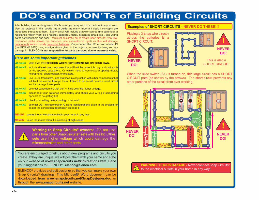
DO’s and DON’Ts of Building CircuitsAfter building the circuits given in this booklet, you may wish to experiment on your own.Use the projects in this booklet as a guide, as many important design concepts areintroduced throughout them. Every circuit will include a power source (the batteries), aresistance (which might be a resistor, capacitor, motor, integrated circuit, etc.), and wiringpaths between them and back. You must be careful not to create “short circuits” (very low-resistance paths across the batteries, see examples at right) as this will damagecomponents and/or quickly drain your batteries. Only connect the U21 microcontroller IC(the PICAXE 08M) using configurations given in the projects, incorrectly doing so maydamage it. ELENCO® is not responsible for parts damaged due to incorrect wiring.
Here are some important guidelines:ALWAYS USE EYE PROTECTION WHEN EXPERIMENTING ON YOUR OWN.ALWAYS include at least one component that will limit the current through a circuit, such
as the speaker, capacitors, ICs (which must be connected properly), motor,microphone, photoresistor, or resistors.
ALWAYS use LEDs, transistors, and switches in conjunction with other components thatwill limit the current through them. Failure to do so will create a short circuitand/or damage those parts.
ALWAYS connect capacitors so that the “+” side gets the higher voltage.ALWAYS disconnect your batteries immediately and check your wiring if something
appears to be getting hot.ALWAYS check your wiring before turning on a circuit.ALWAYS connect U21 microcontroller IC using configurations given in the projects or
as per the connection description on page 5.
NEVER connect to an electrical outlet in your home in any way.
NEVER touch the motor when it is spinning at high speed.
Placing a 3-snap wire directlyacross the batteries is aSHORT CIRCUIT.
This is also aSHORT CIRCUIT.
When the slide switch (S1) is turned on, this large circuit has a SHORTCIRCUIT path (as shown by the arrows). The short circuit prevents anyother portions of the circuit from ever working.
NEVERDO!
NEVERDO!
NEVERDO! NEVER
DO!
Examples of SHORT CIRCUITS - NEVER DO THESE!!!
Warning to Snap Circuits® owners: Do not useparts from other Snap Circuits® sets with this kit. Othersets use higher voltage which could damage themicrocontroller and other parts.
You are encouraged to tell us about new programs and circuits youcreate. If they are unique, we will post them with your name and stateon our website at www.snapcircuits.net/kidkreations.htm. Sendyour suggestions to ELENCO®: [email protected].
ELENCO® provides a circuit designer so that you can make your ownSnap Circuits® drawings. This Microsoft® Word document can bedownloaded from www.snapcircuits.net/SnapDesigner.doc orthrough the www.snapcircuits.net website.
WARNING: SHOCK HAZARD - Never connect Snap Circuits®
to the electrical outlets in your home in any way!
!!
!!
!
Advanced Troubleshooting (Adult supervision recommended)
-8-
ELENCO®
150 Carpenter AvenueWheeling, IL 60090 U.S.A.
Phone: (847) 541-3800Fax: (847) 520-0085
e-mail: [email protected]: www.elenco.com
You may order additional /replacement parts at:www.snapcircuits.net
ELENCO® is not responsible for partsdamaged due to incorrect wiring.
If you suspect you have damaged parts,you can follow this procedure tosystematically determine which ones needreplacing:
(Note: Some of these tests connect an LEDdirectly across the batteries without anothercomponent to limit the current. Normally thismight damage the LED, however Snap Circuits®
LEDs have internal resistors added to protectthem incorrect wiring, and will not be damaged.)
1. LEDs (D1 & D2), motor (M1), speaker(SP), and battery holder (B3): Placebatteries in holder. Place one of the LEDsdirectly across the battery holder (LED + tobattery +), it should light. Do the same forthe motor, it should spin. “Tap” the speakeracross the battery holder contacts, youshould hear static as it touches. If nonework, then replace your batteries andrepeat. If still bad, then the battery holder isdamaged.
2. Jumper wires:Use this mini-circuit to testeach jumperwire, the LEDshould light.
3. Snap wires: Use this mini-circuit to testeach of the snap wires, one at a time. TheLED should light.
4. Slide switch (S1) and Press switch (S2):Use this mini-circuit; if the LED doesn’t lightthen the slideswitch is bad.Replace theslide switchwith the pressswitch to test it.
5. 100W (R1), 1kW (R2), and 10kW (R4)resistors: Use the mini-circuit from test 4but replace the switch with the 100W resistor(R1); the LED will be bright if the resistor isgood. Next use the 1kW and 10kW resistorsin place of the 100W resistor; the LEDshould be dimmer but still light.
6. Microphone (X1) and Photoresistor (RP):Use the mini-circuit from test 4 but replacethe switch with the microphone (X1, + onright); if blowing into the microphone doesnot change the LED brightness then themicrophone is bad. Replace the microphonewith the photoresistor. Waving your handover the photoresistor (changing the lightthat shines on it) should change thebrightness of the LED or the photoresistor isbad.
7. Adjustable resistor (RV): Build Project#A16, the resistor control lever should turnthe LED (D1) on and off; otherwise it is bad.
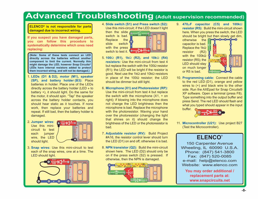
8. NPN transistor (Q2): Build the mini-circuitshown here. The LED (D2) should only beon if the press switch (S2) is pressed. Ifotherwise, then the NPN is damaged.
9. 470mF capacitor (C5) and 100kWresistor (R5): Build the mini-circuit shownhere. When you press the switch, the LEDshould be bright but then slowly get dim,otherwise thecapacitor is bad.Replace the 1kWresistor (R2)with the 100kWresistor (R5); theLED should stayon much longeror R5 is bad.
10. Programming cable: Connect the cableto the red LED (D1), orange and yellowwires to (+) and black wire to the otherside. Run the AXEpad for Snap Circuits®XP software. Open a terminal (press F8).Type something into the output buffer andpress Send. The red LED should flash andwhat you typed should appear in the inputbuffer.
11. Microcontroller (U21): Use project B27(Test the Microcontroller).

Project ListingsPart A - Introductory Projects: These projects introduce you to theSnap Circuits® method of building circuits and show how electroniccomponents work. No computer is needed for these projects (someprojects use the U21 microcontroller, but with a factory-loaded program). Part B - Microcontroller Projects: These projects are anintroduction to microprocessors, and the flexibility they give by being
programmable. A computer is needed to load programs into themicrocontroller, but no other programming knowledge is needed. Themicrocontroller re-programming procedure is explained in project B1. Part C - To Go Further: This section is intended for users whowould like to develop their own programs for the microcontroller. Italso has bonus circuits for owners of other Snap Circuits® models.
-9-
Project # Title Page # A1 Electric Light 11 A2 Controlling Electricity 11 A3 Dancing Motor 12 A4 Electronic Counter 13 A5 Adding Sound to the Counter 14 A6 Daylight Alarm Clock 14 A7 Intruder Alarm 15 A8 Jukebox 16 A9 Counting to the Stars 17 A10 Angles and Distance 18 A11 Flip-Flop 19 A12 Adjustable Light Timer 19 A13 Light Sensitive Timer 20 A14 Shot in the Dark 20 A15 Microphone Control 21 A16 Adjustable Brightness 21 A17 Conduction Detector 21 A18 Slider 22 A19 Parallel Resistors 22 A20 Series Resistors 22 A21 Flying Saucer 23 A22 Transistor 23 A23 Capacitor Battery 24 A24 Blow Off Sound 24 A25 Capacitor Photo Control 25 A26 Capacitor Photo Control with Slow Shut-off 25 A27 Photo Switcher 26 A28 Blow On Sound 26 A29 Scratchy Amplifier 27
Project # Title Page # A30 One Shot 27 B1 Blinker (Programming the Microcontroller) 29 B2 Blinkers 33 B3 Four Outputs 34 B4 Play a Tune 35 B5 Computer Music Box 36 B6 Random Sounds 38 B7 Sloppy Switches 39 B8 Bounceless Switches 40 B9 Jukebox with Terminal 41 B10 Launch Pad 42 B11 Adjustable Blinker 43 B12 Basic Light Meter 44 B13 Capacitor Discharge 45 B14 Sunrise Alarm 46 B15 Photon Counter 47 B16 Photon Kazoo 47 B17 Click Counter 48 B18 Super Click Counter 49 B19 Data Logger 50 B20 Data Logger with Cost 51 B21 24 Hour Data Logger 52 B22 Digital Voltmeter 53 B23 Battery Tester (4V or less) 54 B24 Battery Tester (20V or less) 55 B25 Clap Light 56 B26 Clap Music 57 B27 Test the Microcontroller 58
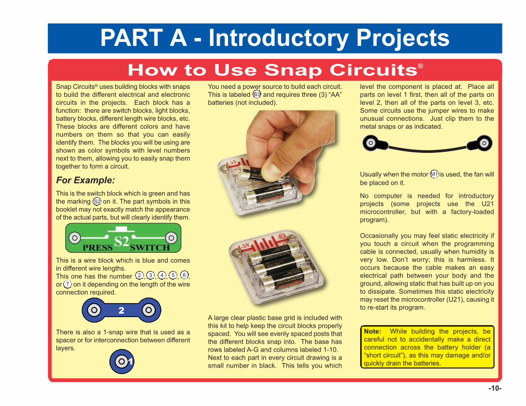
How to Use Snap Circuits®
Snap Circuits® uses building blocks with snapsto build the different electrical and electroniccircuits in the projects. Each block has afunction: there are switch blocks, light blocks,battery blocks, different length wire blocks, etc.These blocks are different colors and havenumbers on them so that you can easilyidentify them. The blocks you will be using areshown as color symbols with level numbersnext to them, allowing you to easily snap themtogether to form a circuit.
For Example:This is the switch block which is green and hasthe marking on it. The part symbols in thisbooklet may not exactly match the appearanceof the actual parts, but will clearly identify them.
This is a wire block which is blue and comesin different wire lengths.This one has the number , , , , ,or on it depending on the length of the wireconnection required.
There is also a 1-snap wire that is used as aspacer or for interconnection between differentlayers.
You need a power source to build each circuit.This is labeled and requires three (3) “AA”batteries (not included).
A large clear plastic base grid is included withthis kit to help keep the circuit blocks properlyspaced. You will see evenly spaced posts thatthe different blocks snap into. The base hasrows labeled A-G and columns labeled 1-10.Next to each part in every circuit drawing is asmall number in black. This tells you which
level the component is placed at. Place allparts on level 1 first, then all of the parts onlevel 2, then all of the parts on level 3, etc.Some circuits use the jumper wires to makeunusual connections. Just clip them to themetal snaps or as indicated.
Usually when the motor is used, the fan willbe placed on it.
No computer is needed for introductoryprojects (some projects use the U21microcontroller, but with a factory-loadedprogram).
Occasionally you may feel static electricity ifyou touch a circuit when the programmingcable is connected, usually when humidity isvery low. Don’t worry; this is harmless. Itoccurs because the cable makes an easyelectrical path between your body and theground, allowing static that has built up on youto dissipate. Sometimes this static electricitymay reset the microcontroller (U21), causing itto re-start its program.
Note: While building the projects, becareful not to accidentally make a directconnection across the battery holder (a“short circuit”), as this may damage and/orquickly drain the batteries.
S2
2 3 4 5 6
B3
-10-
PART A - Introductory Projects
7
M1
-11-
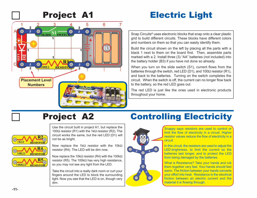
Project A1 Electric Light
Snap Circuits® uses electronic blocks that snap onto a clear plasticgrid to build different circuits. These blocks have different colorsand numbers on them so that you can easily identify them. Build the circuit shown on the left by placing all the parts with ablack 1 next to them on the board first. Then, assemble partsmarked with a 2. Install three (3) “AA” batteries (not included) intothe battery holder (B3) if you have not done so already.When you turn on the slide switch (S1), current flows from thebatteries through the switch, red LED (D1), and 100W resistor (R1),and back to the batteries. Turning on the switch completes thecircuit. When the switch is off, the current can no longer flow backto the battery, so the red LED goes out. The red LED is just like the ones used in electronic productsthroughout your home.
+
Placement LevelNumbers
+
Use the circuit built in project A1, but replace the100W resistor (R1) with the 1kW resistor (R2). Thecircuit works the same, but the red LED (D1) willnot be as bright.
Now replace the 1kW resistor with the 10kWresistor (R4). The LED will be dim now.
Now replace the 10kW resistor (R4) with the 100kWresistor (R5). The 100kW has very high resistance,so you may not see any light from the LED.
Take the circuit into a really dark room or curl yourfingers around the LED to block the surroundinglight. Now you see that the LED is on, though verydim.
Project A2 Controlling ElectricitySnappy says resistors are used to control orlimit the flow of electricity in a circuit. Higherresistor values reduce the flow of electricity in acircuit.
In this circuit, the resistors are used to adjust theLED brightness, to limit the current so thebatteries last longer, and to protect the LEDfrom being damaged by the batteries.
What is Resistance? Take your hands and rubthem together very fast. Your hands should feelwarm. The friction between your hands convertsyour effort into heat. Resistance is the electricalfriction between an electric current and thematerial it is flowing through.
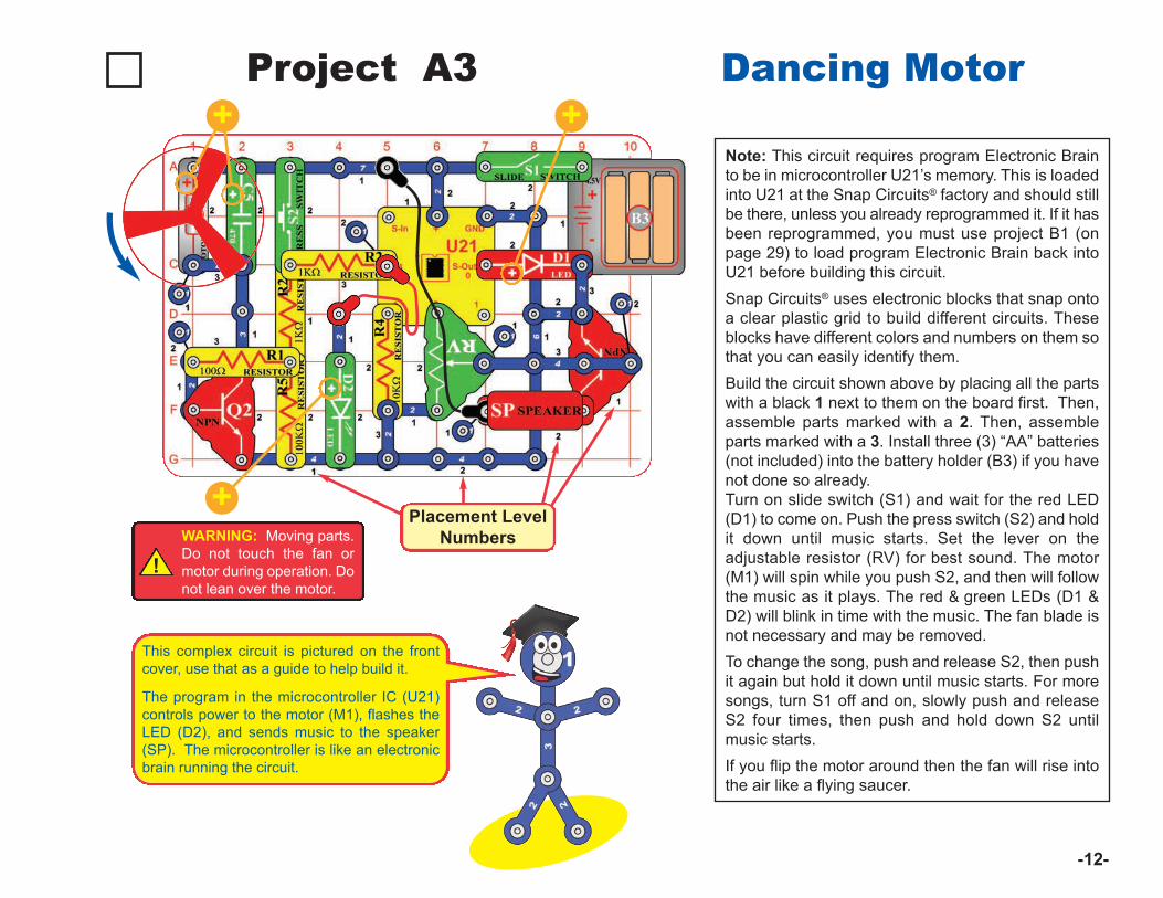
Note: This circuit requires program Electronic Brainto be in microcontroller U21’s memory. This is loadedinto U21 at the Snap Circuits® factory and should stillbe there, unless you already reprogrammed it. If it hasbeen reprogrammed, you must use project B1 (onpage 29) to load program Electronic Brain back intoU21 before building this circuit. Snap Circuits® uses electronic blocks that snap ontoa clear plastic grid to build different circuits. Theseblocks have different colors and numbers on them sothat you can easily identify them. Build the circuit shown above by placing all the partswith a black 1 next to them on the board first. Then,assemble parts marked with a 2. Then, assembleparts marked with a 3. Install three (3) “AA” batteries(not included) into the battery holder (B3) if you havenot done so already.Turn on slide switch (S1) and wait for the red LED(D1) to come on. Push the press switch (S2) and holdit down until music starts. Set the lever on theadjustable resistor (RV) for best sound. The motor(M1) will spin while you push S2, and then will followthe music as it plays. The red & green LEDs (D1 &D2) will blink in time with the music. The fan blade isnot necessary and may be removed. To change the song, push and release S2, then pushit again but hold it down until music starts. For moresongs, turn S1 off and on, slowly push and releaseS2 four times, then push and hold down S2 untilmusic starts. If you flip the motor around then the fan will rise intothe air like a flying saucer.
Project A3 Dancing Motor
Placement LevelNumbers
-12-
+
!WARNING: Moving parts.Do not touch the fan ormotor during operation. Donot lean over the motor.
+
This complex circuit is pictured on the frontcover, use that as a guide to help build it.
The program in the microcontroller IC (U21)controls power to the motor (M1), flashes theLED (D2), and sends music to the speaker(SP). The microcontroller is like an electronicbrain running the circuit.
+
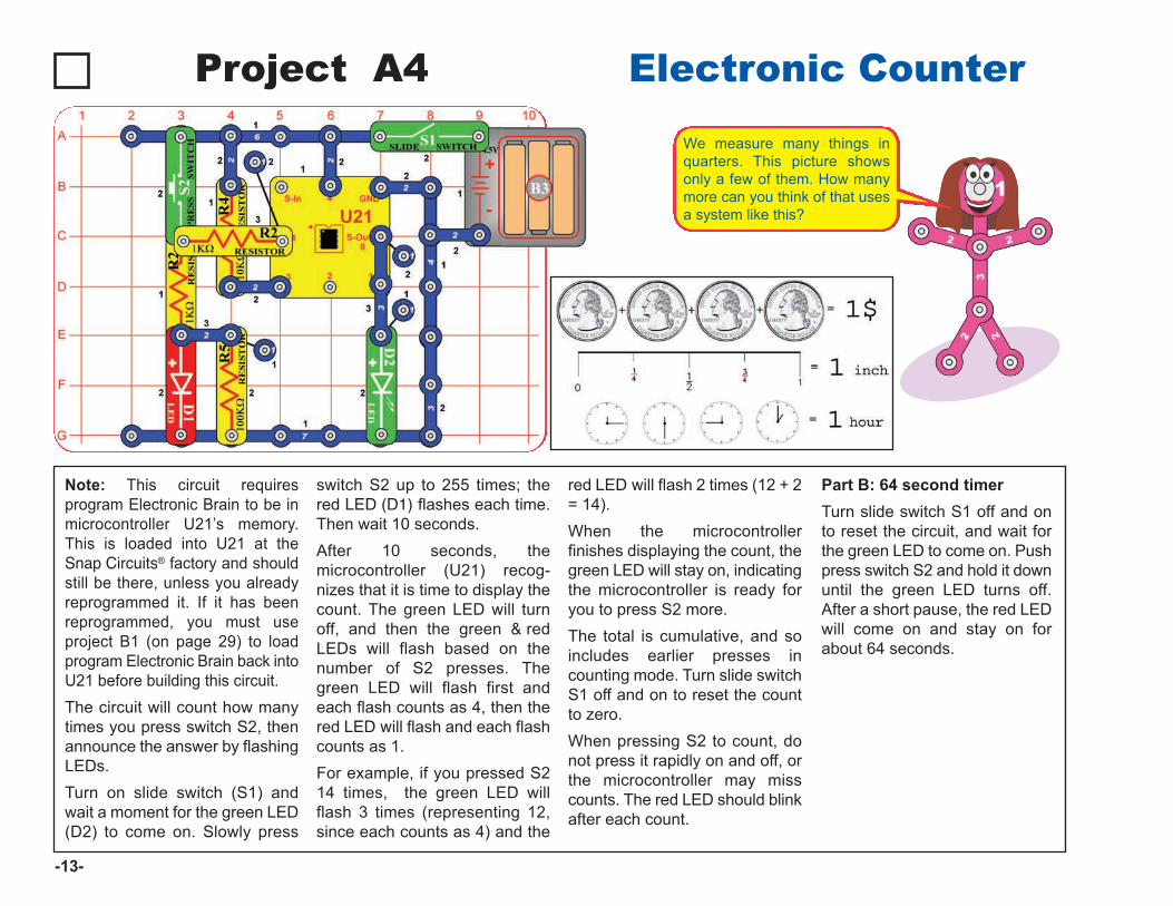
Project A4 Electronic Counter
Note: This circuit requiresprogram Electronic Brain to be inmicrocontroller U21’s memory.This is loaded into U21 at theSnap Circuits® factory and shouldstill be there, unless you alreadyreprogrammed it. If it has beenreprogrammed, you must useproject B1 (on page 29) to loadprogram Electronic Brain back intoU21 before building this circuit. The circuit will count how manytimes you press switch S2, thenannounce the answer by flashingLEDs. Turn on slide switch (S1) andwait a moment for the green LED(D2) to come on. Slowly press
switch S2 up to 255 times; thered LED (D1) flashes each time.Then wait 10 seconds. After 10 seconds, themicrocontroller (U21) recog-nizes that it is time to display thecount. The green LED will turnoff, and then the green & redLEDs will flash based on thenumber of S2 presses. Thegreen LED will flash first andeach flash counts as 4, then thered LED will flash and each flashcounts as 1. For example, if you pressed S214 times, the green LED willflash 3 times (representing 12,since each counts as 4) and the
red LED will flash 2 times (12 + 2= 14). When the microcontrollerfinishes displaying the count, thegreen LED will stay on, indicatingthe microcontroller is ready foryou to press S2 more. The total is cumulative, and soincludes earlier presses incounting mode. Turn slide switchS1 off and on to reset the countto zero. When pressing S2 to count, donot press it rapidly on and off, orthe microcontroller may misscounts. The red LED should blinkafter each count.
Part B: 64 second timerTurn slide switch S1 off and onto reset the circuit, and wait forthe green LED to come on. Pushpress switch S2 and hold it downuntil the green LED turns off.After a short pause, the red LEDwill come on and stay on forabout 64 seconds.
-13-
We measure many things inquarters. This picture showsonly a few of them. How manymore can you think of that usesa system like this?
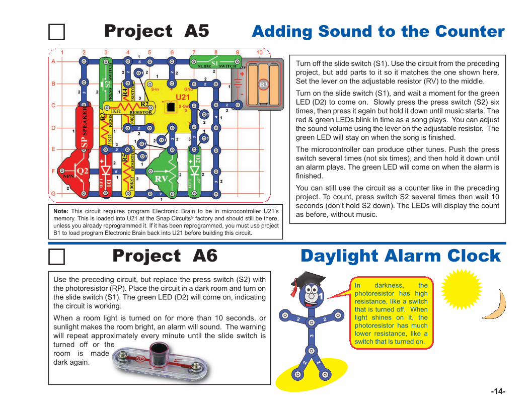
Turn off the slide switch (S1). Use the circuit from the precedingproject, but add parts to it so it matches the one shown here.Set the lever on the adjustable resistor (RV) to the middle.Turn on the slide switch (S1), and wait a moment for the greenLED (D2) to come on. Slowly press the press switch (S2) sixtimes, then press it again but hold it down until music starts. Thered & green LEDs blink in time as a song plays. You can adjustthe sound volume using the lever on the adjustable resistor. Thegreen LED will stay on when the song is finished.
The microcontroller can produce other tunes. Push the pressswitch several times (not six times), and then hold it down untilan alarm plays. The green LED will come on when the alarm isfinished.You can still use the circuit as a counter like in the precedingproject. To count, press switch S2 several times then wait 10seconds (don’t hold S2 down). The LEDs will display the countas before, without music.
Project A5 Adding Sound to the Counter
Project A6 Daylight Alarm Clock
Note: This circuit requires program Electronic Brain to be in microcontroller U21’smemory. This is loaded into U21 at the Snap Circuits® factory and should still be there,unless you already reprogrammed it. If it has been reprogrammed, you must use projectB1 to load program Electronic Brain back into U21 before building this circuit.
-14-
Use the preceding circuit, but replace the press switch (S2) withthe photoresistor (RP). Place the circuit in a dark room and turn onthe slide switch (S1). The green LED (D2) will come on, indicatingthe circuit is working. When a room light is turned on for more than 10 seconds, orsunlight makes the room bright, an alarm will sound. The warningwill repeat approximately every minute until the slide switch isturned off or theroom is madedark again.
In darkness, thephotoresistor has highresistance, like a switchthat is turned off. Whenlight shines on it, thephotoresistor has muchlower resistance, like aswitch that is turned on.
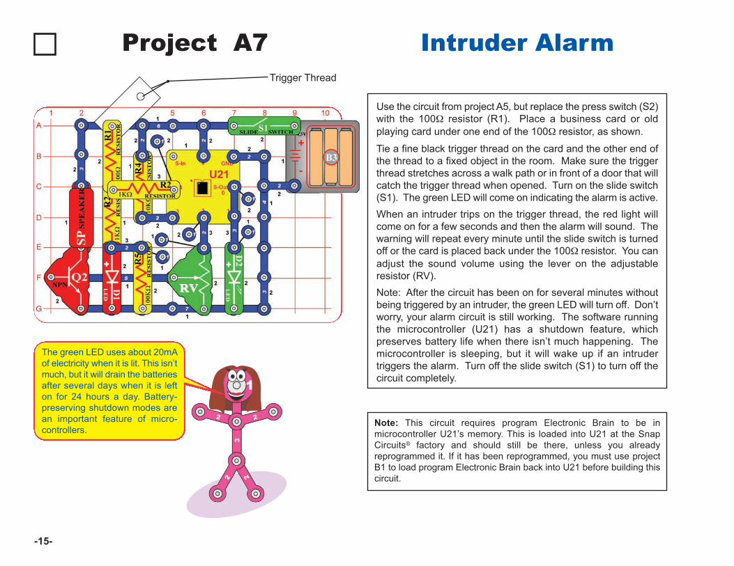
Use the circuit from project A5, but replace the press switch (S2)with the 100W resistor (R1). Place a business card or oldplaying card under one end of the 100W resistor, as shown.
Tie a fine black trigger thread on the card and the other end ofthe thread to a fixed object in the room. Make sure the triggerthread stretches across a walk path or in front of a door that willcatch the trigger thread when opened. Turn on the slide switch(S1). The green LED will come on indicating the alarm is active. When an intruder trips on the trigger thread, the red light willcome on for a few seconds and then the alarm will sound. Thewarning will repeat every minute until the slide switch is turnedoff or the card is placed back under the 100W resistor. You canadjust the sound volume using the lever on the adjustableresistor (RV).Note: After the circuit has been on for several minutes withoutbeing triggered by an intruder, the green LED will turn off. Don’tworry, your alarm circuit is still working. The software runningthe microcontroller (U21) has a shutdown feature, whichpreserves battery life when there isn’t much happening. Themicrocontroller is sleeping, but it will wake up if an intrudertriggers the alarm. Turn off the slide switch (S1) to turn off thecircuit completely.
Note: This circuit requires program Electronic Brain to be inmicrocontroller U21’s memory. This is loaded into U21 at the SnapCircuits® factory and should still be there, unless you alreadyreprogrammed it. If it has been reprogrammed, you must use projectB1 to load program Electronic Brain back into U21 before building thiscircuit.
Project A7 Intruder Alarm Trigger Thread
-15-
The green LED uses about 20mAof electricity when it is lit. This isn’tmuch, but it will drain the batteriesafter several days when it is lefton for 24 hours a day. Battery-preserving shutdown modes arean important feature of micro-controllers.
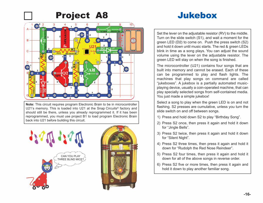
Set the lever on the adjustable resistor (RV) to the middle.Turn on the slide switch (S1), and wait a moment for thegreen LED (D2) to come on. Push the press switch (S2)and hold it down until music starts. The red & green LEDsblink in time as a song plays. You can adjust the soundvolume using the lever on the adjustable resistor. Thegreen LED will stay on when the song is finished.
The microcontroller (U21) contains four songs that arebuilt into memory and cannot be erased. Each of thesecan be programmed to play and flash lights. Themachines that play songs on command are called“jukeboxes”. A jukebox is a partially automated music-playing device, usually a coin-operated machine, that canplay specially selected songs from self-contained media.You just made a simple jukebox!Select a song to play when the green LED is on and notflashing. S2 presses are cumulative, unless you turn theslide switch on and off between songs. 1) Press and hold down S2 to play “Birthday Song”.2) Press S2 once, then press it again and hold it down
for “Jingle Bells”.3) Press S2 twice, then press it again and hold it down
for “Silent Night”. 4) Press S2 three times, then press it again and hold it
down for “Rudolph the Red Nose Reindeer”.5) Press S2 four times, then press it again and hold it
down for all of the above songs in reverse order. 6) Press S2 five or more times, then press it again and
hold it down to play another familiar song.
Project A8 Jukebox
CAN YOU PLAYTHREE BLIND MICE?
-16-
Note: This circuit requires program Electronic Brain to be in microcontrollerU21’s memory. This is loaded into U21 at the Snap Circuits® factory andshould still be there, unless you already reprogrammed it. If it has beenreprogrammed, you must use project B1 to load program Electronic Brainback into U21 before building this circuit.
Project A9 Counting To The Stars
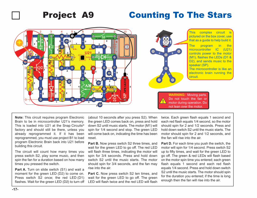
Note: This circuit requires program ElectronicBrain to be in microcontroller U21’s memory.This is loaded into U21 at the Snap Circuits®
factory and should still be there, unless youalready reprogrammed it. If it has beenreprogrammed, you must use project B1 to loadprogram Electronic Brain back into U21 beforebuilding this circuit. The circuit will count how many times youpress switch S2, play some music, and thenspin the fan for a duration based on how manytimes you pressed the switch. Part A. Turn on slide switch (S1) and wait amoment for the green LED (D2) to come on.Press switch S2 once; the red LED (D1)flashes. Wait for the green LED (D2) to turn off
(about 10 seconds after you press S2). Whenthe green LED comes back on, press and holddown S2 until music starts. The motor (M1) willspin for 1/4 second and stop. The green LEDwill come back on, indicating the time has beenreset.Part B. Now press switch S2 three times, andwait for the green LED to go off. The red LEDwill flash three times, indicating the motor willspin for 3/4 seconds. Press and hold downswitch S2 until the music starts. The motorshould spin for 3/4 seconds, and the fan mayrise into the air. Part C. Now press switch S2 ten times, andwait for the green LED to go off. The greenLED will flash twice and the red LED will flash
twice. Each green flash equals 1 second andeach red flash equals 1/4 second, so the motorshould spin for 2 and 1/2 seconds. Press andhold down switch S2 until the music starts. Themotor should spin for 2 and 1/2 seconds, andthe fan will rise into the air.Part D. For each time you push the switch, themotor will spin for 1/4 second. Press switch S2up to fifty times, and wait for the green LED togo off. The green & red LEDs will flash basedon the motor spin time you entered; each greenflash equals 1 second and each red flashequals 1/4 second. Press and hold down switchS2 until the music starts. The motor should spinfor the duration you entered; if the time is longenough then the fan will rise into the air.
-17-
!WARNING: Moving parts.Do not touch the fan ormotor during operation. Donot lean over the motor.
This complex circuit ispictured on the box cover, usethat as a guide to help build it.
The program in themicrocontroller IC (U21)controls power to the motor(M1), flashes the LEDs (D1 &D2), and sends music to thespeaker (SP).The microcontroller is like anelectronic brain running thecircuit.
+
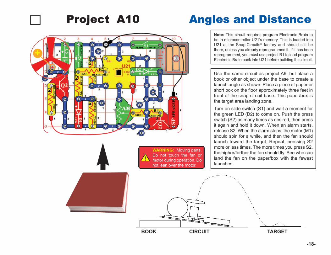
Project A10 Angles and Distance
Use the same circuit as project A9, but place abook or other object under the base to create alaunch angle as shown. Place a piece of paper orshort box on the floor approximately three feet infront of the snap circuit base. This paper/box isthe target area landing zone. Turn on slide switch (S1) and wait a moment forthe green LED (D2) to come on. Push the pressswitch (S2) as many times as desired, then pressit again and hold it down. When an alarm starts,release S2. When the alarm stops, the motor (M1)should spin for a while, and then the fan shouldlaunch toward the target. Repeat, pressing S2more or less times. The more times you press S2,the higher/farther the fan should fly. See who canland the fan on the paper/box with the fewestlaunches.
BOOK CIRCUIT TARGET
!WARNING: Moving parts.Do not touch the fan ormotor during operation. Donot lean over the motor.
Note: This circuit requires program Electronic Brain tobe in microcontroller U21’s memory. This is loaded intoU21 at the Snap Circuits® factory and should still bethere, unless you already reprogrammed it. If it has beenreprogrammed, you must use project B1 to load programElectronic Brain back into U21 before building this circuit.
-18-
+
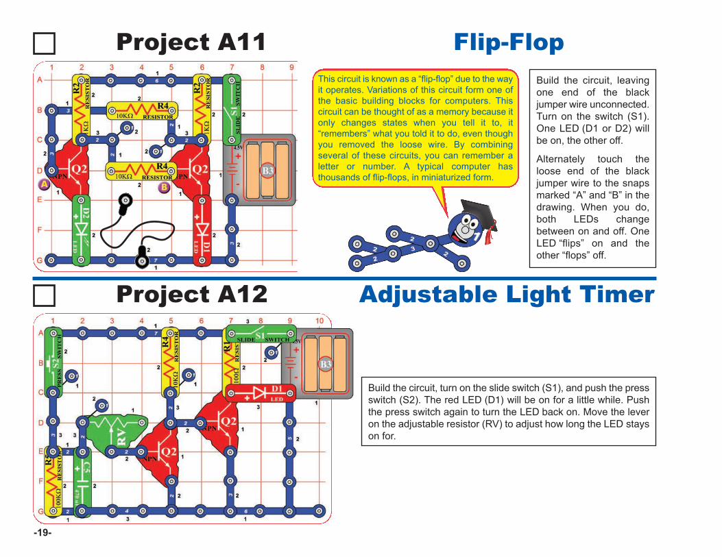
Project A11Build the circuit, leavingone end of the blackjumper wire unconnected.Turn on the switch (S1).One LED (D1 or D2) willbe on, the other off.
Alternately touch theloose end of the blackjumper wire to the snapsmarked “A” and “B” in thedrawing. When you do,both LEDs changebetween on and off. OneLED “flips” on and theother “flops” off.
Flip-Flop
Project A12
Build the circuit, turn on the slide switch (S1), and push the pressswitch (S2). The red LED (D1) will be on for a little while. Pushthe press switch again to turn the LED back on. Move the leveron the adjustable resistor (RV) to adjust how long the LED stayson for.
Adjustable Light Timer
-19-
This circuit is known as a “flip-flop” due to the wayit operates. Variations of this circuit form one ofthe basic building blocks for computers. Thiscircuit can be thought of as a memory because itonly changes states when you tell it to, it“remembers” what you told it to do, even thoughyou removed the loose wire. By combiningseveral of these circuits, you can remember aletter or number. A typical computer hasthousands of flip-flops, in miniaturized form.
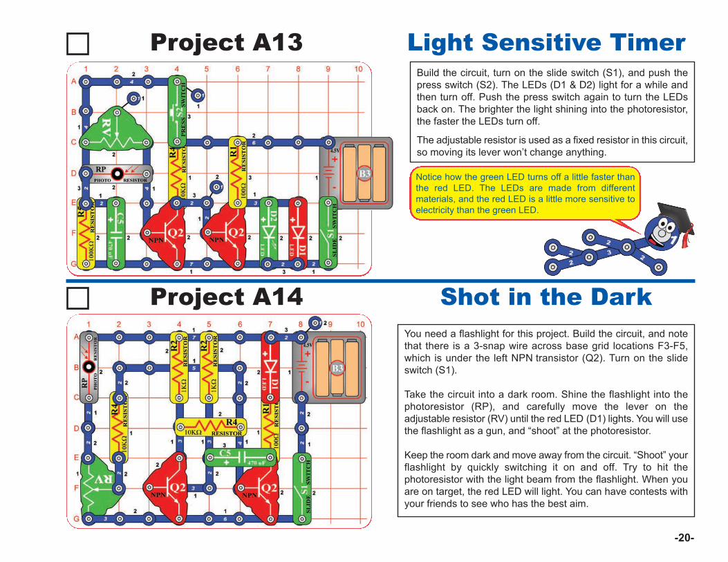
Project A13Build the circuit, turn on the slide switch (S1), and push thepress switch (S2). The LEDs (D1 & D2) light for a while andthen turn off. Push the press switch again to turn the LEDsback on. The brighter the light shining into the photoresistor,the faster the LEDs turn off.
The adjustable resistor is used as a fixed resistor in this circuit,so moving its lever won’t change anything.
Light Sensitive Timer
Project A14You need a flashlight for this project. Build the circuit, and notethat there is a 3-snap wire across base grid locations F3-F5,which is under the left NPN transistor (Q2). Turn on the slideswitch (S1).
Take the circuit into a dark room. Shine the flashlight into thephotoresistor (RP), and carefully move the lever on theadjustable resistor (RV) until the red LED (D1) lights. You will usethe flashlight as a gun, and “shoot” at the photoresistor.
Keep the room dark and move away from the circuit. “Shoot” yourflashlight by quickly switching it on and off. Try to hit thephotoresistor with the light beam from the flashlight. When youare on target, the red LED will light. You can have contests withyour friends to see who has the best aim.
Shot in the Dark
-20-
Notice how the green LED turns off a little faster thanthe red LED. The LEDs are made from differentmaterials, and the red LED is a little more sensitive toelectricity than the green LED.
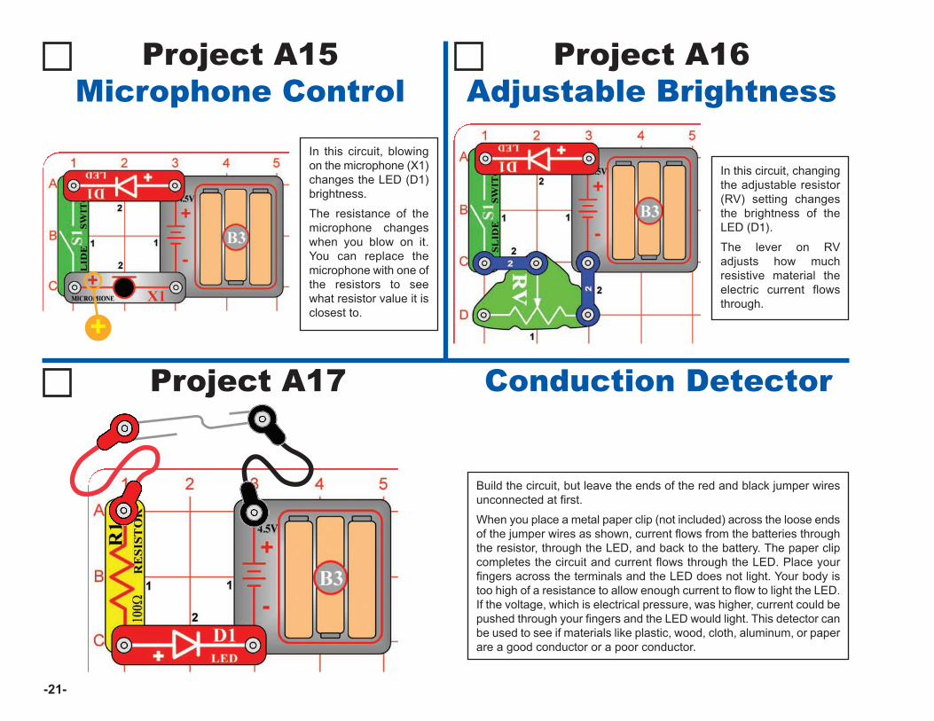
Project A17
Build the circuit, but leave the ends of the red and black jumper wiresunconnected at first.
When you place a metal paper clip (not included) across the loose endsof the jumper wires as shown, current flows from the batteries throughthe resistor, through the LED, and back to the battery. The paper clipcompletes the circuit and current flows through the LED. Place yourfingers across the terminals and the LED does not light. Your body istoo high of a resistance to allow enough current to flow to light the LED.If the voltage, which is electrical pressure, was higher, current could bepushed through your fingers and the LED would light. This detector canbe used to see if materials like plastic, wood, cloth, aluminum, or paperare a good conductor or a poor conductor.
Conduction Detector
Project A15Microphone Control
In this circuit, blowingon the microphone (X1)changes the LED (D1)brightness.
The resistance of themicrophone changeswhen you blow on it.You can replace themicrophone with one ofthe resistors to seewhat resistor value it isclosest to.
Project A16Adjustable Brightness
In this circuit, changingthe adjustable resistor(RV) setting changesthe brightness of theLED (D1).
The lever on RVadjusts how muchresistive material theelectric current flowsthrough.
-21-
+
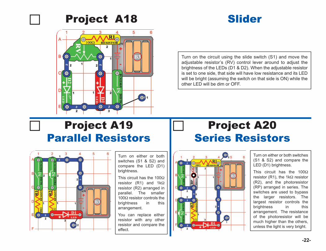
Turn on the circuit using the slide switch (S1) and move theadjustable resistor’s (RV) control lever around to adjust thebrightness of the LEDs (D1 & D2). When the adjustable resistoris set to one side, that side will have low resistance and its LEDwill be bright (assuming the switch on that side is ON) while theother LED will be dim or OFF.
Project A19Parallel Resistors
Project A20Series Resistors
Project A18 Slider
-22-
Turn on either or bothswitches (S1 & S2) andcompare the LED (D1)brightness.
This circuit has the 100Wresistor (R1) and 1kWresistor (R2) arranged inparallel. The smaller100W resistor controls thebrightness in thisarrangement.
You can replace eitherresistor with any otherresistor and compare theeffect.
Turn on either or both switches(S1 & S2) and compare theLED (D1) brightness.
This circuit has the 100Wresistor (R1), the 1kW resistor(R2), and the photoresistor(RP) arranged in series. Theswitches are used to bypassthe larger resistors. Thelargest resistor controls thebrightness in thisarrangement. The resistanceof the photoresistor will bemuch higher than the others,unless the light is very bright.
Project #A21
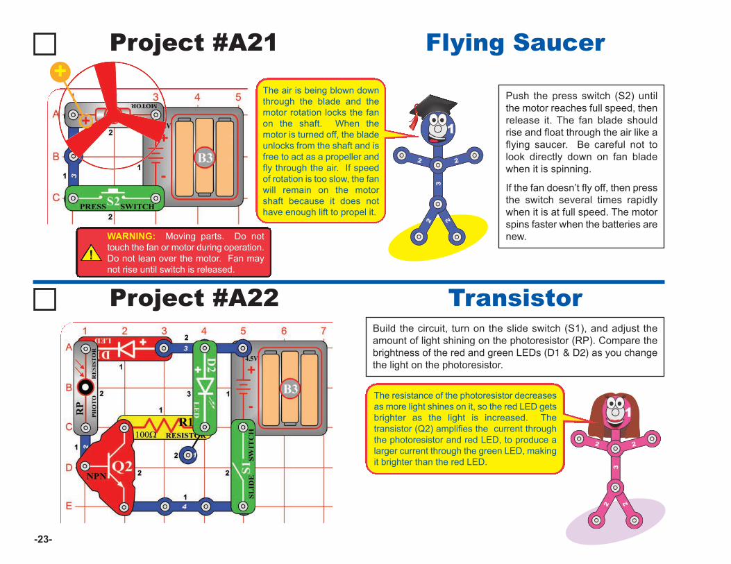
Push the press switch (S2) untilthe motor reaches full speed, thenrelease it. The fan blade shouldrise and float through the air like aflying saucer. Be careful not tolook directly down on fan bladewhen it is spinning.
If the fan doesn’t fly off, then pressthe switch several times rapidlywhen it is at full speed. The motorspins faster when the batteries arenew.
Flying Saucer
Project #A22Build the circuit, turn on the slide switch (S1), and adjust theamount of light shining on the photoresistor (RP). Compare thebrightness of the red and green LEDs (D1 & D2) as you changethe light on the photoresistor.
Transistor
!WARNING: Moving parts. Do nottouch the fan or motor during operation.Do not lean over the motor. Fan maynot rise until switch is released.
-23-
The air is being blown downthrough the blade and themotor rotation locks the fanon the shaft. When themotor is turned off, the bladeunlocks from the shaft and isfree to act as a propeller andfly through the air. If speedof rotation is too slow, the fanwill remain on the motorshaft because it does nothave enough lift to propel it.
The resistance of the photoresistor decreasesas more light shines on it, so the red LED getsbrighter as the light is increased. Thetransistor (Q2) amplifies the current throughthe photoresistor and red LED, to produce alarger current through the green LED, makingit brighter than the red LED.
+
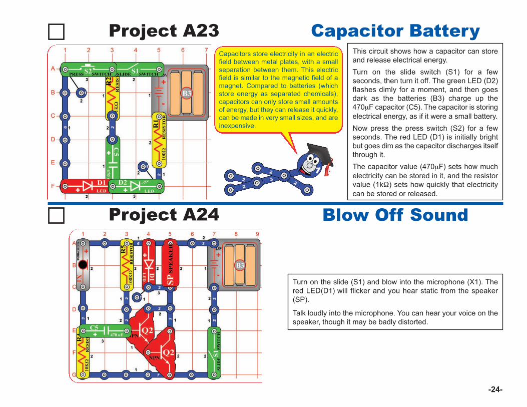
This circuit shows how a capacitor can storeand release electrical energy. Turn on the slide switch (S1) for a fewseconds, then turn it off. The green LED (D2)flashes dimly for a moment, and then goesdark as the batteries (B3) charge up the470mF capacitor (C5). The capacitor is storingelectrical energy, as if it were a small battery. Now press the press switch (S2) for a fewseconds. The red LED (D1) is initially brightbut goes dim as the capacitor discharges itselfthrough it.The capacitor value (470mF) sets how muchelectricity can be stored in it, and the resistorvalue (1kW) sets how quickly that electricitycan be stored or released.
Capacitor BatteryProject A23
Turn on the slide (S1) and blow into the microphone (X1). Thered LED(D1) will flicker and you hear static from the speaker(SP).
Talk loudly into the microphone. You can hear your voice on thespeaker, though it may be badly distorted.
Blow Off SoundProject A24
-24-
Capacitors store electricity in an electricfield between metal plates, with a smallseparation between them. This electricfield is similar to the magnetic field of amagnet. Compared to batteries (whichstore energy as separated chemicals),capacitors can only store small amountsof energy, but they can release it quickly,can be made in very small sizes, and areinexpensive.
Project #A25 Capacitor Photo Control
Project #A26
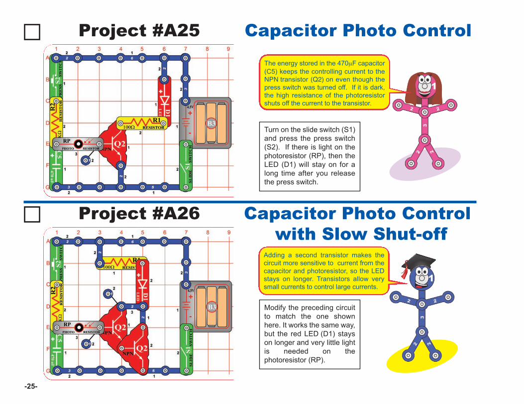
Modify the preceding circuitto match the one shownhere. It works the same way,but the red LED (D1) stayson longer and very little lightis needed on thephotoresistor (RP).
Capacitor Photo Controlwith Slow Shut-off
Adding a second transistor makes thecircuit more sensitive to current from thecapacitor and photoresistor, so the LEDstays on longer. Transistors allow verysmall currents to control large currents.
-25-
Turn on the slide switch (S1)and press the press switch(S2). If there is light on thephotoresistor (RP), then theLED (D1) will stay on for along time after you releasethe press switch.
The energy stored in the 470mF capacitor(C5) keeps the controlling current to theNPN transistor (Q2) on even though thepress switch was turned off. If it is dark,the high resistance of the photoresistorshuts off the current to the transistor.
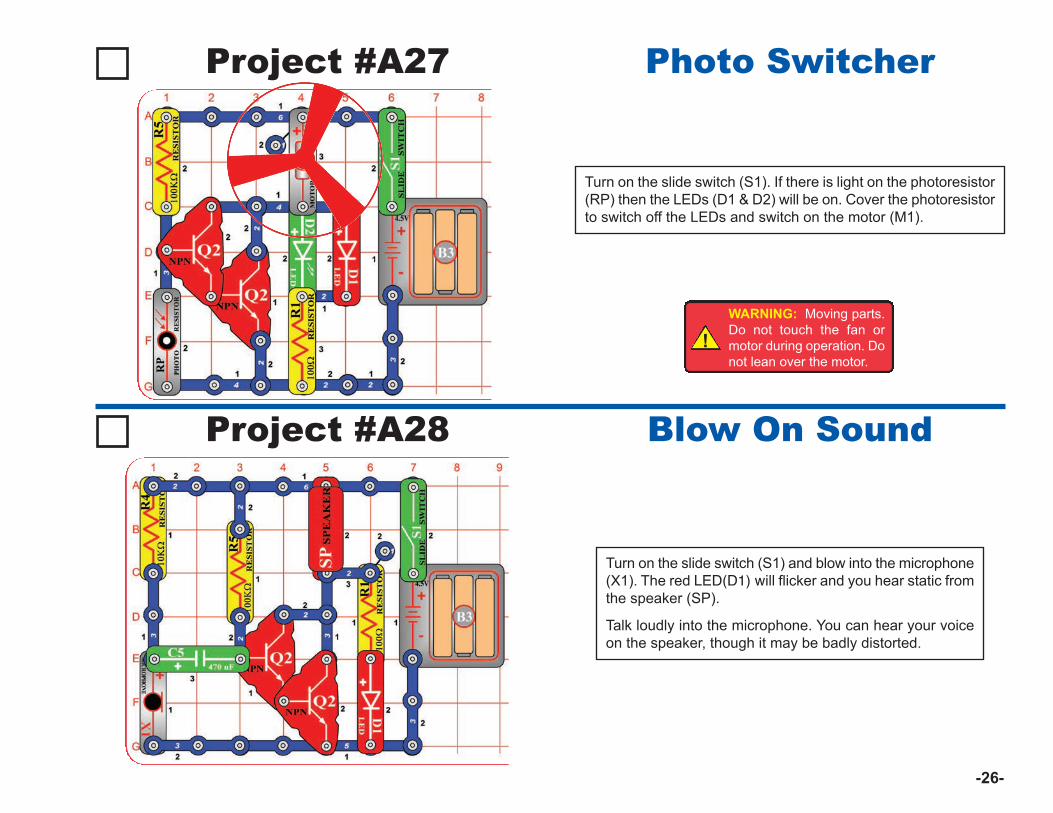
Project #A27
Turn on the slide switch (S1). If there is light on the photoresistor(RP) then the LEDs (D1 & D2) will be on. Cover the photoresistorto switch off the LEDs and switch on the motor (M1).
Photo Switcher
Project #A28
Turn on the slide switch (S1) and blow into the microphone(X1). The red LED(D1) will flicker and you hear static fromthe speaker (SP).
Talk loudly into the microphone. You can hear your voiceon the speaker, though it may be badly distorted.
Blow On Sound
!WARNING: Moving parts.Do not touch the fan ormotor during operation. Donot lean over the motor.
-26-
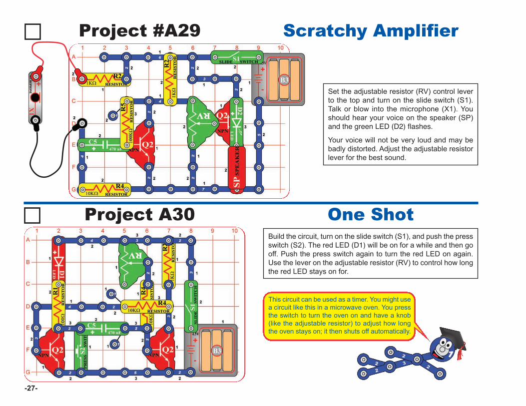
Project #A29
Set the adjustable resistor (RV) control leverto the top and turn on the slide switch (S1).Talk or blow into the microphone (X1). Youshould hear your voice on the speaker (SP)and the green LED (D2) flashes.
Your voice will not be very loud and may bebadly distorted. Adjust the adjustable resistorlever for the best sound.
Scratchy Amplifier
-27-
Project A30Build the circuit, turn on the slide switch (S1), and push the pressswitch (S2). The red LED (D1) will be on for a while and then gooff. Push the press switch again to turn the red LED on again.Use the lever on the adjustable resistor (RV) to control how longthe red LED stays on for.
One Shot
This circuit can be used as a timer. You might usea circuit like this in a microwave oven. You pressthe switch to turn the oven on and have a knob(like the adjustable resistor) to adjust how longthe oven stays on; it then shuts off automatically.
Introduction
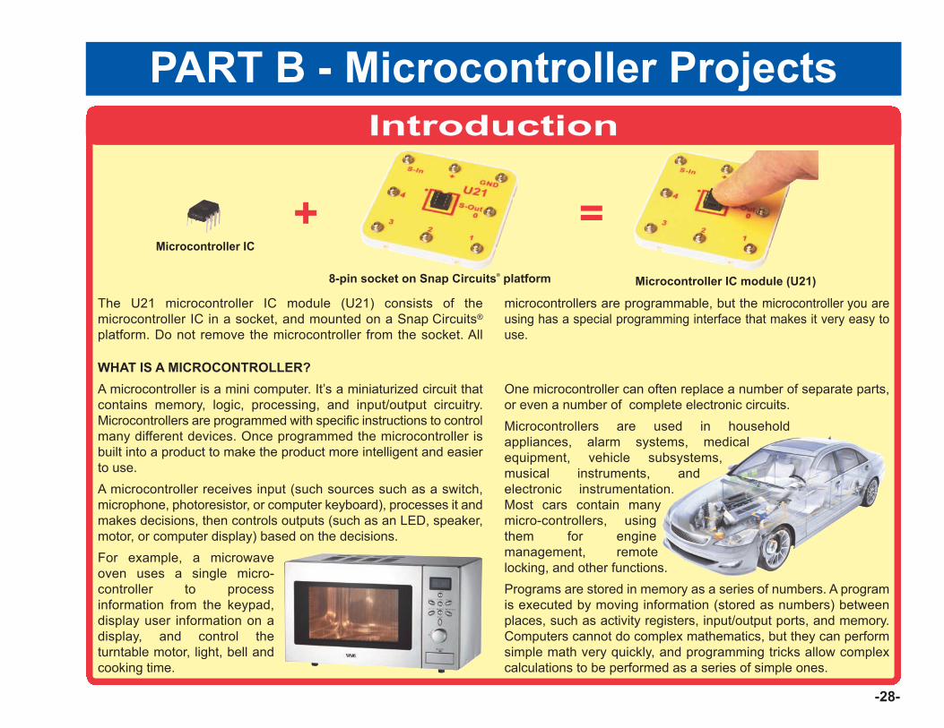
The U21 microcontroller IC module (U21) consists of themicrocontroller IC in a socket, and mounted on a Snap Circuits®
platform. Do not remove the microcontroller from the socket. All
microcontrollers are programmable, but the microcontroller you areusing has a special programming interface that makes it very easy touse.
WHAT IS A MICROCONTROLLER?A microcontroller is a mini computer. It’s a miniaturized circuit thatcontains memory, logic, processing, and input/output circuitry.Microcontrollers are programmed with specific instructions to controlmany different devices. Once programmed the microcontroller isbuilt into a product to make the product more intelligent and easierto use.A microcontroller receives input (such sources such as a switch,microphone, photoresistor, or computer keyboard), processes it andmakes decisions, then controls outputs (such as an LED, speaker,motor, or computer display) based on the decisions. For example, a microwaveoven uses a single micro-controller to processinformation from the keypad,display user information on adisplay, and control theturntable motor, light, bell andcooking time.
One microcontroller can often replace a number of separate parts,or even a number of complete electronic circuits.Microcontrollers are used in householdappliances, alarm systems, medicalequipment, vehicle subsystems,musical instruments, andelectronic instrumentation.Most cars contain manymicro-controllers, usingthem for enginemanagement, remotelocking, and other functions.Programs are stored in memory as a series of numbers. A programis executed by moving information (stored as numbers) betweenplaces, such as activity registers, input/output ports, and memory.Computers cannot do complex mathematics, but they can performsimple math very quickly, and programming tricks allow complexcalculations to be performed as a series of simple ones.
Microcontroller IC module (U21)8-pin socket on Snap Circuits® platform
Microcontroller IC
+
PART B - Microcontroller Projects
-28-
=
Project B1
-29-
Installing Software and Programming Cable
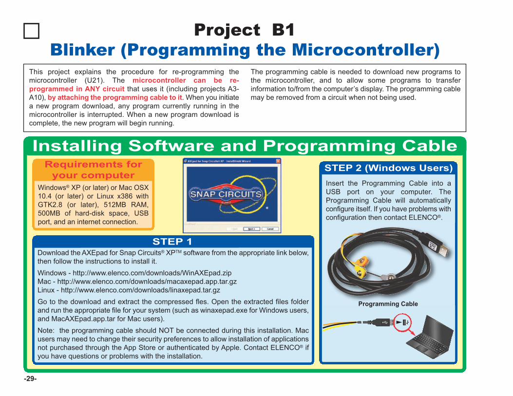
Windows® XP (or later) or Mac OSX10.4 (or later) or Linux x386 withGTK2.8 (or later), 512MB RAM,500MB of hard-disk space, USBport, and an internet connection.
Blinker (Programming the Microcontroller)This project explains the procedure for re-programming themicrocontroller (U21). The microcontroller can be re-programmed in ANY circuit that uses it (including projects A3-A10), by attaching the programming cable to it. When you initiatea new program download, any program currently running in themicrocontroller is interrupted. When a new program download iscomplete, the new program will begin running.
The programming cable is needed to download new programs tothe microcontroller, and to allow some programs to transferinformation to/from the computer’s display. The programming cablemay be removed from a circuit when not being used.
Requirements foryour computer
STEP 1
STEP 2 (Windows Users)Insert the Programming Cable into aUSB port on your computer. TheProgramming Cable will automaticallyconfigure itself. If you have problems withconfiguration then contact ELENCO®.
Programming Cable
Download the AXEpad for Snap Circuits® XPTM software from the appropriate link below,then follow the instructions to install it. Windows - http://www.elenco.com/downloads/WinAXEpad.zipMac - http://www.elenco.com/downloads/macaxepad.app.tar.gzLinux - http://www.elenco.com/downloads/linaxepad.tar.gzGo to the download and extract the compressed fles. Open the extracted files folderand run the appropriate file for your system (such as winaxepad.exe for Windows users,and MacAXEpad.app.tar for Mac users). Note: the programming cable should NOT be connected during this installation. Macusers may need to change their security preferences to allow installation of applicationsnot purchased through the App Store or authenticated by Apple. Contact ELENCO® ifyou have questions or problems with the installation.
How to Use AXEpad
-30-
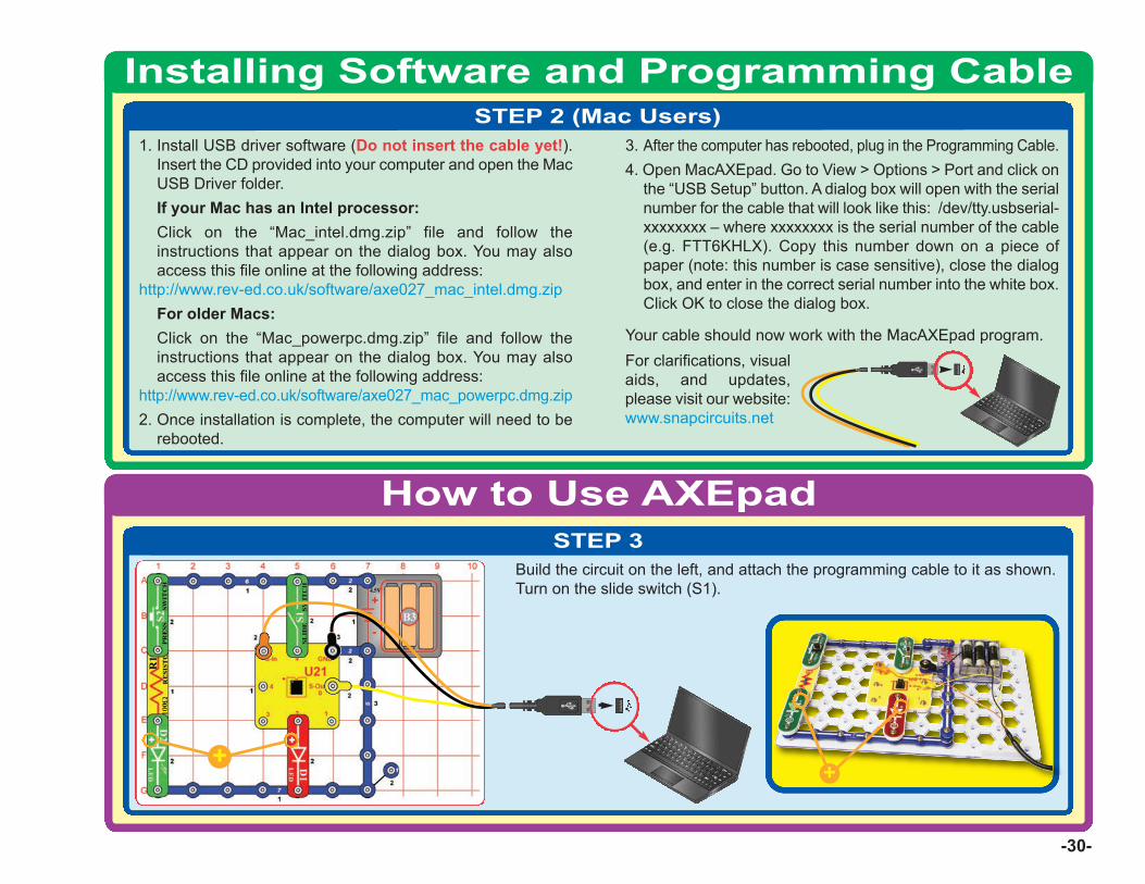
Installing Software and Programming CableSTEP 2 (Mac Users)
STEP 3Build the circuit on the left, and attach the programming cable to it as shown.Turn on the slide switch (S1).
++
1. Install USB driver software (Do not insert the cable yet!).Insert the CD provided into your computer and open the MacUSB Driver folder.If your Mac has an Intel processor:Click on the “Mac_intel.dmg.zip” file and follow theinstructions that appear on the dialog box. You may alsoaccess this file online at the following address:
http://www.rev-ed.co.uk/software/axe027_mac_intel.dmg.zipFor older Macs:Click on the “Mac_powerpc.dmg.zip” file and follow theinstructions that appear on the dialog box. You may alsoaccess this file online at the following address:
http://www.rev-ed.co.uk/software/axe027_mac_powerpc.dmg.zip2. Once installation is complete, the computer will need to be
rebooted.
3. After the computer has rebooted, plug in the Programming Cable.4. Open MacAXEpad. Go to View > Options > Port and click on
the “USB Setup” button. A dialog box will open with the serialnumber for the cable that will look like this: /dev/tty.usbserial-xxxxxxxx – where xxxxxxxx is the serial number of the cable(e.g. FTT6KHLX). Copy this number down on a piece ofpaper (note: this number is case sensitive), close the dialogbox, and enter in the correct serial number into the white box.Click OK to close the dialog box.
Your cable should now work with the MacAXEpad program.For clarifications, visualaids, and updates,please visit our website:www.snapcircuits.net
-31-
How to Use AXEpadSTEP 4
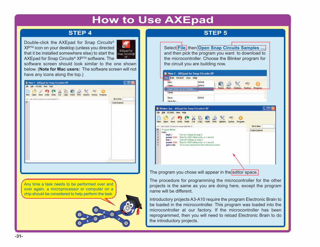
Double-click the AXEpad for Snap Circuits®
XPTM icon on your desktop (unless you directedthat it be installed somewhere else) to start theAXEpad for Snap Circuits® XPTM software. Thesoftware screen should look similar to the one shownbelow. (Note for Mac users: The software screen will nothave any icons along the top.)
STEP 5
The program you chose will appear in the editor space.
The procedure for programming the microcontroller for the otherprojects is the same as you are doing here, except the programname will be different.
Introductory projects A3-A10 require the program Electronic Brain tobe loaded in the microcontroller. This program was loaded into themicrocontroller at our factory. If the microcontroller has beenreprogrammed, then you will need to reload Electronic Brain to dothe introductory projects.
Select File, then Open Snap Circuits Samples ...,and then pick the program you want to download tothe microcontroller. Choose the Blinker program forthe circuit you are building now.
Any time a task needs to be performed over andover again, a microprocessor or computer on achip should be considered to help perform the task.

-32-
How to Use AXEpadSTEP 6
Click Program to download your program tothe microcontroller. This will interrupt and erasethe program currently in the microcontroller.(Note for Mac users: Since there is noProgram icon, you must click on the PICAXEmenu tab and select Program, or simply pressF5 on your keyboard.) A window will open forthe download process, like the one shown here:
Window for Downloading Process
A message will tell you when the new program download is complete, and the newprogram will begin running. If you turn off the microcontroller, the program in it will restart when the microcontrolleris turned back on. The programming cable may be removed after the program download is finished; it isusually not needed for running the program. Some Snap Circuits® XPTM projects will usethe cable to enter or display information using the computer screen while a program isrunning, these will tell you to keep the cable connected after program download.
STEP 7The Blinker program should now be running in the microcontroller,and the red LED (D1) should be blinking.
Push the press switch (S2) several times to make the green LED(D2) blink. Try to make the green LED blink at the same rate as thered LED. It is probably much easier to let the microcontroller blinkthe red LED, rather than blink the green LED by pressing the switch.
TROUBLESHOOTINGIf you get an error while trying to download a program,start the download and then reset the microcontroller(turn slide switch S1 off and on) just after the words“Downloading program” are displayed. A runningprogram will be interrupted by a new download when itexecutes a command, but some commands (such as longpause or wait commands) can take too long to complete,so the download could be ignored. Resetting themicrocontroller just after initiating a download ensures thatthe microcontroller will recognize the new download. If youstill can’t download, use the Advanced Troubleshootingprocedure on page 8.
If you get an error saying the Download Cable cannotbe found: make sure you have the Programming Cableconnected. If this is the first time using your programmingcable, you may need to manually select thecommunication port for it. (Note: the Download Cable isyour Programming Cable.) For Windows® Computers:select Optionsthen Portthen pick a COM port to try(pick the highest-numbered port first).Close the Options window and try to Program again.
If an error message appears,see Troubleshooting.

-33-
OPTIONAL - TO LEARN ABOUT PROGRAMMING You can edit the program to changeparameters or commands if desired. Theediting procedure is similar to other Windows®
word processors. You may also type in acompletely new program. To save programsyou have created or modified, use Save Asunder File menu.
Only valid programs (without errors) may bedownloaded, or a downloading error will result.You can check for errors by clicking theSyntax box, and then clicking Program.Syntax also tells you how much memory theprogram uses; programs must be of 256 bytesof memory or less. All Snap Circuits® XPTM
programs have already been checked forerrors.
Explanations for all the microcontrollercommands, and some basic information aboutprogramming, can be found under the Help menuat Snap Circuits® XPTM. Use this file to look up a command you want tolearn about. If you later want to write your ownprograms, you’ll need to use this often. Part C - ToGo Further (page 59) has other useful information. The PICAXE® Manual (Parts 1, 2, and 3) has moredetailed explanations of the PICAXE® commands,and other information about PICAXE® products,however much of this information is not applicableto Snap Circuits® XPTM and some is very technical.The Snap Circuits® XPTM help file is customized toyour product.
Here is how the program works:
high 2 - this tells the microcontroller to putan electrical voltage at out put 2 (wherethe red LED is connected). This voltagewill light the LED.
pause 1000 - this tells the microcontrollerto pause for 1000 milliseconds, or 1second, before performing the nextinstruction.
low 2 - this tells the microcontroller to turnoff or remove any voltage at output 2. Thiswill turn off the red LED.
goto main - this tells the microcontrollerto execute the instructions next to “main:”,which here means repeating theinstruction set. This causes the LED toturn on and off, blinking continuously.
Information after an apostrophe (‘) symbol isComments. Comments are a description ofwhat the program is doing, to help youunderstand and remember it. Comments areignored by the microcontroller.
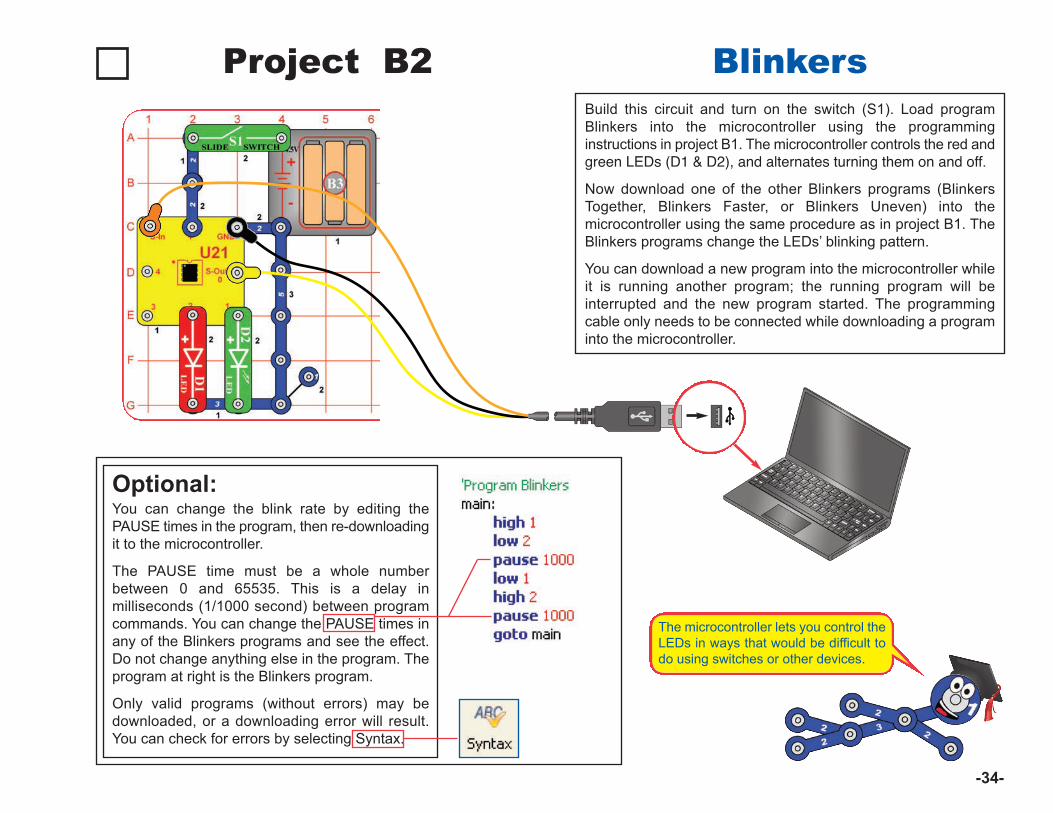
Build this circuit and turn on the switch (S1). Load programBlinkers into the microcontroller using the programminginstructions in project B1. The microcontroller controls the red andgreen LEDs (D1 & D2), and alternates turning them on and off.
Now download one of the other Blinkers programs (BlinkersTogether, Blinkers Faster, or Blinkers Uneven) into themicrocontroller using the same procedure as in project B1. TheBlinkers programs change the LEDs’ blinking pattern.
You can download a new program into the microcontroller whileit is running another program; the running program will beinterrupted and the new program started. The programmingcable only needs to be connected while downloading a programinto the microcontroller.
Project B2 Blinkers
Optional:You can change the blink rate by editing thePAUSE times in the program, then re-downloadingit to the microcontroller.
The PAUSE time must be a whole numberbetween 0 and 65535. This is a delay inmilliseconds (1/1000 second) between programcommands. You can change the PAUSE times inany of the Blinkers programs and see the effect.Do not change anything else in the program. Theprogram at right is the Blinkers program.
Only valid programs (without errors) may bedownloaded, or a downloading error will result.You can check for errors by selecting Syntax.
The microcontroller lets you control theLEDs in ways that would be difficult todo using switches or other devices.
-34-
-35-
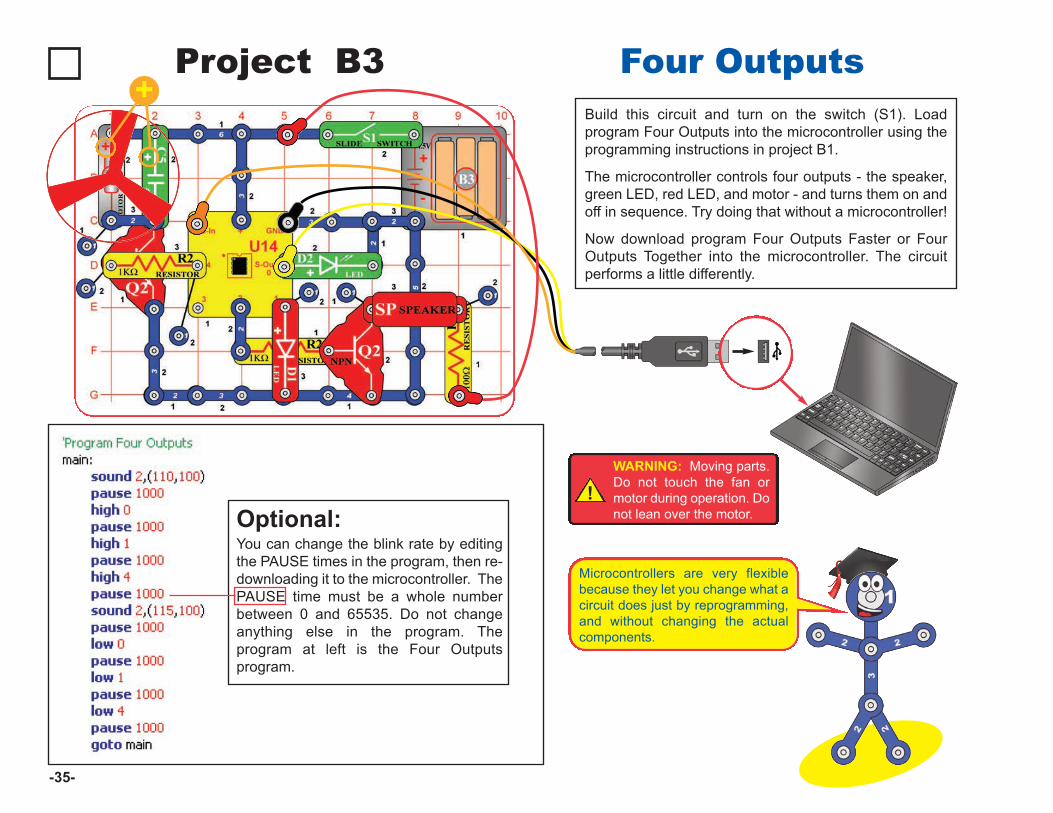
Build this circuit and turn on the switch (S1). Loadprogram Four Outputs into the microcontroller using theprogramming instructions in project B1.
The microcontroller controls four outputs - the speaker,green LED, red LED, and motor - and turns them on andoff in sequence. Try doing that without a microcontroller!
Now download program Four Outputs Faster or FourOutputs Together into the microcontroller. The circuitperforms a little differently.
Project B3 Four Outputs
Optional: You can change the blink rate by editingthe PAUSE times in the program, then re-downloading it to the microcontroller. ThePAUSE time must be a whole numberbetween 0 and 65535. Do not changeanything else in the program. Theprogram at left is the Four Outputsprogram.
Microcontrollers are very flexiblebecause they let you change what acircuit does just by reprogramming,and without changing the actualcomponents.
+
!WARNING: Moving parts.Do not touch the fan ormotor during operation. Donot lean over the motor.
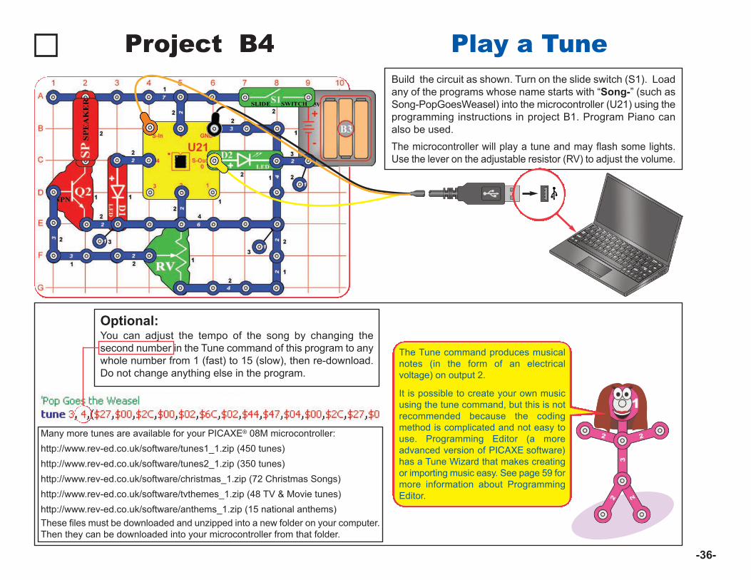
Project B4 Play a Tune
Optional: You can adjust the tempo of the song by changing thesecond number in the Tune command of this program to anywhole number from 1 (fast) to 15 (slow), then re-download.Do not change anything else in the program.
-36-
The Tune command produces musicalnotes (in the form of an electricalvoltage) on output 2.
It is possible to create your own musicusing the tune command, but this is notrecommended because the codingmethod is complicated and not easy touse. Programming Editor (a moreadvanced version of PICAXE software)has a Tune Wizard that makes creatingor importing music easy. See page 59 formore information about ProgrammingEditor.
Many more tunes are available for your PICAXE® 08M microcontroller:http://www.rev-ed.co.uk/software/tunes1_1.zip (450 tunes)http://www.rev-ed.co.uk/software/tunes2_1.zip (350 tunes)http://www.rev-ed.co.uk/software/christmas_1.zip (72 Christmas Songs)http://www.rev-ed.co.uk/software/tvthemes_1.zip (48 TV & Movie tunes)http://www.rev-ed.co.uk/software/anthems_1.zip (15 national anthems)These files must be downloaded and unzipped into a new folder on your computer.Then they can be downloaded into your microcontroller from that folder.
Build the circuit as shown. Turn on the slide switch (S1). Loadany of the programs whose name starts with “Song-” (such asSong-PopGoesWeasel) into the microcontroller (U21) using theprogramming instructions in project B1. Program Piano canalso be used.The microcontroller will play a tune and may flash some lights.Use the lever on the adjustable resistor (RV) to adjust the volume.
-37-
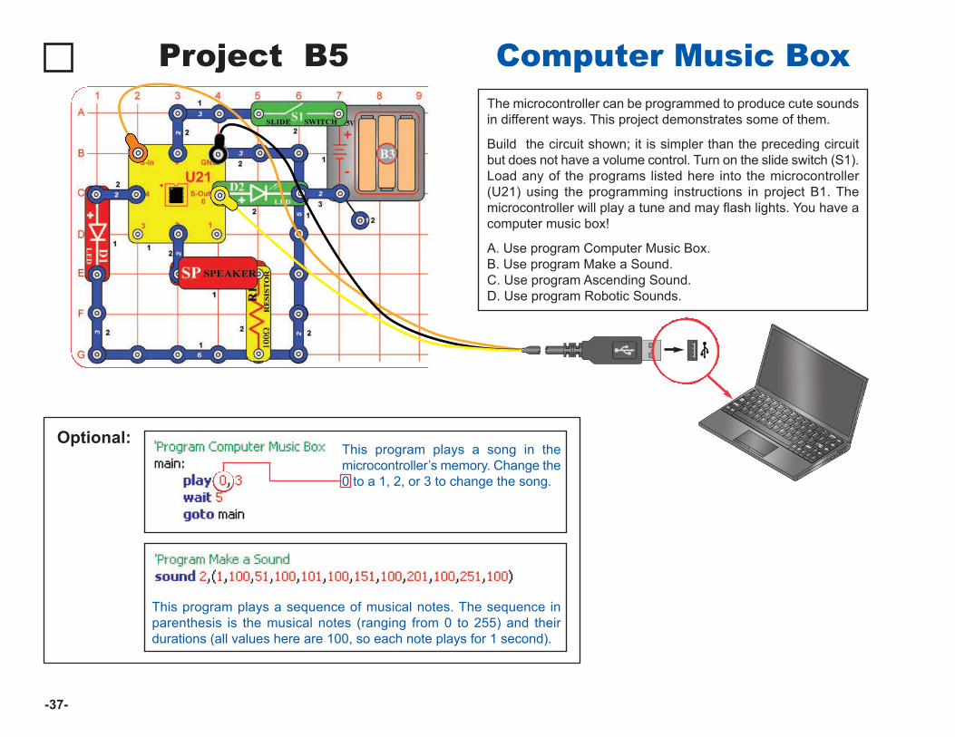
The microcontroller can be programmed to produce cute soundsin different ways. This project demonstrates some of them.
Build the circuit shown; it is simpler than the preceding circuitbut does not have a volume control. Turn on the slide switch (S1).Load any of the programs listed here into the microcontroller(U21) using the programming instructions in project B1. Themicrocontroller will play a tune and may flash lights. You have acomputer music box!
A. Use program Computer Music Box. B. Use program Make a Sound.C. Use program Ascending Sound.D. Use program Robotic Sounds.
Project B5 Computer Music Box
Optional: This program plays a song in themicrocontroller’s memory. Change the0 to a 1, 2, or 3 to change the song.
This program plays a sequence of musical notes. The sequence inparenthesis is the musical notes (ranging from 0 to 255) and theirdurations (all values here are 100, so each note plays for 1 second).
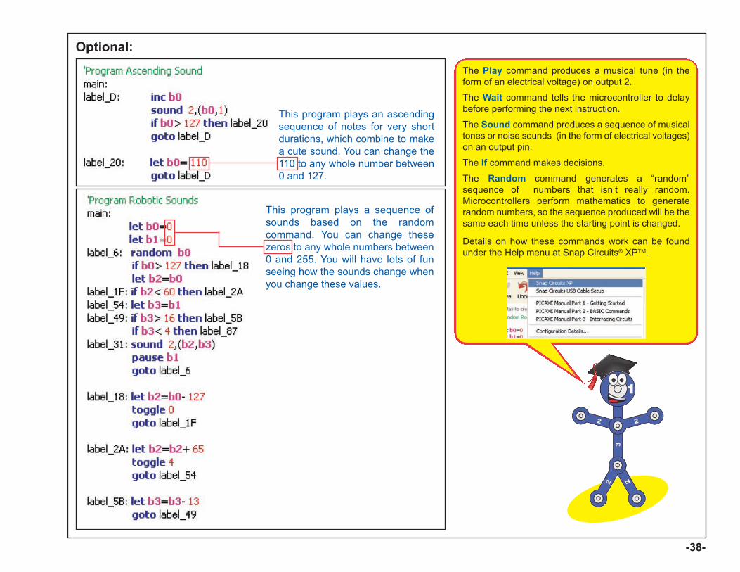
This program plays an ascendingsequence of notes for very shortdurations, which combine to makea cute sound. You can change the110 to any whole number between0 and 127.
This program plays a sequence ofsounds based on the randomcommand. You can change thesezeros to any whole numbers between0 and 255. You will have lots of funseeing how the sounds change whenyou change these values.
-38-
Optional: The Play command produces a musical tune (in theform of an electrical voltage) on output 2.
The Wait command tells the microcontroller to delaybefore performing the next instruction.
The Sound command produces a sequence of musicaltones or noise sounds (in the form of electrical voltages)on an output pin.
The If command makes decisions.
The Random command generates a “random”sequence of numbers that isn’t really random.Microcontrollers perform mathematics to generaterandom numbers, so the sequence produced will be thesame each time unless the starting point is changed.
Details on how these commands work can be foundunder the Help menu at Snap Circuits® XPTM.
-39-
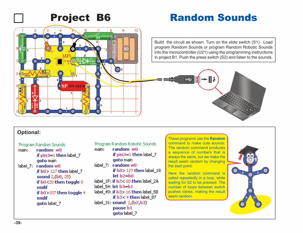
Project B6 Random Sounds
Build the circuit as shown. Turn on the slide switch (S1). Loadprogram Random Sounds or program Random Robotic Soundsinto the microcontroller (U21) using the programming instructionsin project B1. Push the press switch (S2) and listen to the sounds.
Optional: These programs use the Randomcommand to make cute sounds.The random command producesa sequence of numbers that isalways the same, but we make theresult seem random by changingthe start point.
Here the random command iscalled repeatedly in a loop, whilewaiting for S2 to be pressed. Thenumber of loops between switchpushes varies, making the resultseem random.
Project B7 Sloppy Switches
Optional:
-40-
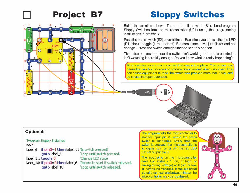
The program tells the microcontroller tomonitor input pin 3, where the pressswitch is connected. Every time theswitch is pressed, the microcontroller isto toggle (turn on or off) the red LED(D1) at output pin 0.
The input pins on the microcontrollerhave two states - 1 (on, or high, orhaving strong voltage) or 0 (off, or low,or having no voltage). If the electricalsignal is somewhere between these, themicrocontroller may get confused.
Build the circuit as shown. Turn on the slide switch (S1). Load programSloppy Switches into the microcontroller (U21) using the programminginstructions in project B1. Push the press switch (S2) several times. Each time you press it the red LED(D1) should toggle (turn on or off). But sometimes it will just flicker and notchange. Press the switch enough times to see this happen. This effect makes it appear the switch isn’t working, or the microcontrollerisn’t watching it carefully enough. Do you know what is really happening?
Most switches use a metal contact that snaps into place. This action maycause the switch to bounce and produce “switch noise” when it is closed. Thiscan cause equipment to think the switch was pressed more than once, andso cause improper operation.
-41-
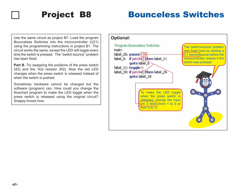
Use the same circuit as project B7. Load the programBounceless Switches into the microcontroller (U21)using the programming instructions in project B1. Thecircuit works the same, except the LED will toggle everytime the switch is pressed. The “switch bounce” problemhas been fixed.
Part B. Try swapping the positions of the press switch(S2) and the 1kW resistor (R2). Now the red LEDchanges when the press switch is released instead ofwhen the switch is pushed.
Sometimes hardware cannot be changed but thesoftware (program) can. How could you change theflowchart program to make the LED toggle when thepress switch is released using the original circuit?Snappy knows how.
Project B8 Bounceless Switches
Optional:
The “switch bounce” problemwas fixed here by adding a0.1 second pause before themicrocontroller checks if theswitch was pressed.
To make the LED togglewhen the press switch isreleased, change the inputpin 3 tests (from 1 to 0 orfrom 0 to 1).
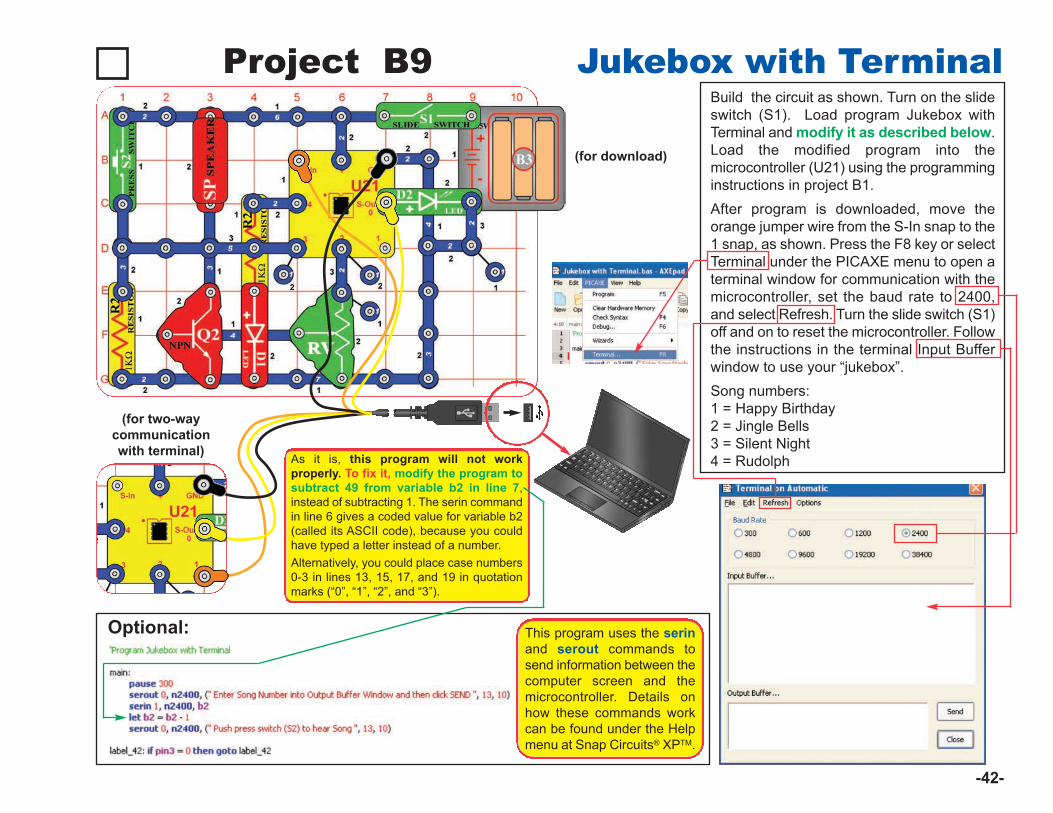
As it is, this program will not workproperly. To fix it, modify the program tosubtract 49 from variable b2 in line 7,instead of subtracting 1. The serin commandin line 6 gives a coded value for variable b2(called its ASCII code), because you couldhave typed a letter instead of a number. Alternatively, you could place case numbers0-3 in lines 13, 15, 17, and 19 in quotationmarks (“0”, “1”, “2”, and “3”).
Project B9 Jukebox with Terminal
-42-
Build the circuit as shown. Turn on the slideswitch (S1). Load program Jukebox withTerminal and modify it as described below.Load the modified program into themicrocontroller (U21) using the programminginstructions in project B1. After program is downloaded, move theorange jumper wire from the S-In snap to the1 snap, as shown. Press the F8 key or selectTerminal under the PICAXE menu to open aterminal window for communication with themicrocontroller, set the baud rate to 2400,and select Refresh. Turn the slide switch (S1)off and on to reset the microcontroller. Followthe instructions in the terminal Input Bufferwindow to use your “jukebox”. Song numbers:1 = Happy Birthday2 = Jingle Bells 3 = Silent Night4 = Rudolph
Optional:
(for two-waycommunicationwith terminal)
(for download)
This program uses the serinand serout commands tosend information between thecomputer screen and themicrocontroller. Details onhow these commands workcan be found under the Helpmenu at Snap Circuits® XPTM.
-43-
(for two-way communicationwith terminal)
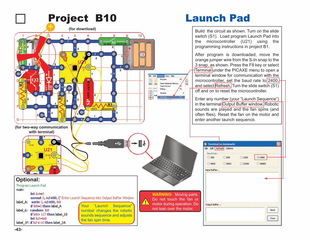
Project B10 Launch PadBuild the circuit as shown. Turn on the slideswitch (S1). Load program Launch Pad intothe microcontroller (U21) using theprogramming instructions in project B1.
After program is downloaded, move theorange jumper wire from the S-In snap to the3 snap, as shown. Press the F8 key or selectTerminal under the PICAXE menu to open aterminal window for communication with themicrocontroller, set the baud rate to 2400,and select Refresh. Turn the slide switch (S1)off and on to reset the microcontroller.
Enter any number (your “Launch Sequence”)in the terminal Output Buffer window. Roboticsounds are played and the fan spins (andoften flies). Reset the fan on the motor andenter another launch sequence.
Optional:
!WARNING: Moving parts.Do not touch the fan ormotor during operation. Donot lean over the motor.
Your “Launch Sequence”number changes the roboticsounds sequence and adjuststhe fan spin time.
(for download)+
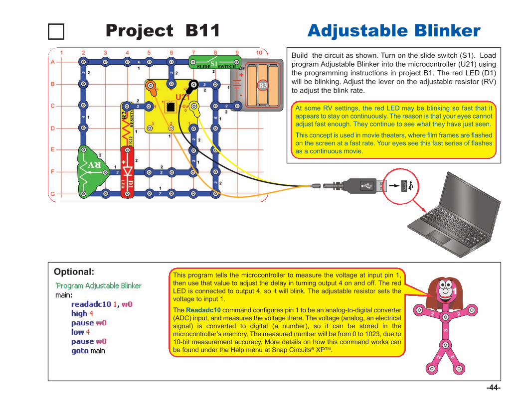
Project B11 Adjustable BlinkerBuild the circuit as shown. Turn on the slide switch (S1). Loadprogram Adjustable Blinker into the microcontroller (U21) usingthe programming instructions in project B1. The red LED (D1)will be blinking. Adjust the lever on the adjustable resistor (RV)to adjust the blink rate.
Optional:
-44-
At some RV settings, the red LED may be blinking so fast that itappears to stay on continuously. The reason is that your eyes cannotadjust fast enough. They continue to see what they have just seen.
This concept is used in movie theaters, where film frames are flashedon the screen at a fast rate. Your eyes see this fast series of flashesas a continuous movie.
This program tells the microcontroller to measure the voltage at input pin 1,then use that value to adjust the delay in turning output 4 on and off. The redLED is connected to output 4, so it will blink. The adjustable resistor sets thevoltage to input 1.
The Readadc10 command configures pin 1 to be an analog-to-digital converter(ADC) input, and measures the voltage there. The voltage (analog, an electricalsignal) is converted to digital (a number), so it can be stored in themicrocontroller’s memory. The measured number will be from 0 to 1023, due to10-bit measurement accuracy. More details on how this command works canbe found under the Help menu at Snap Circuits® XPTM.
-45-
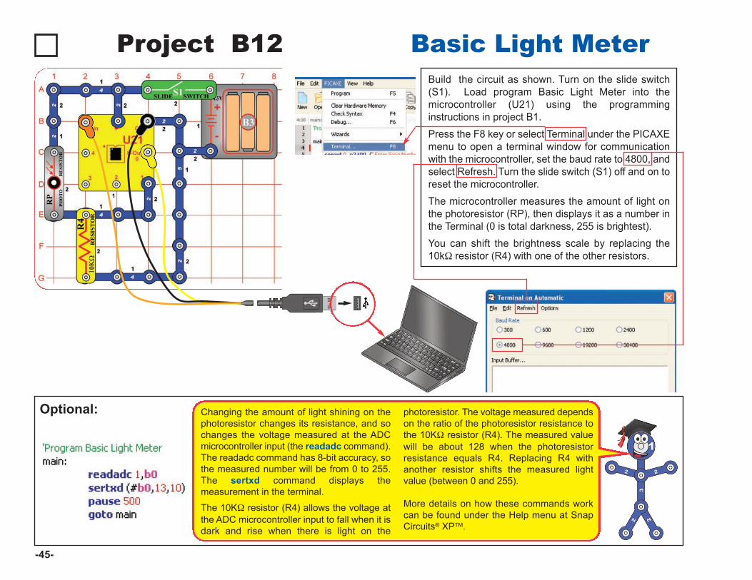
Project B12 Basic Light MeterBuild the circuit as shown. Turn on the slide switch(S1). Load program Basic Light Meter into themicrocontroller (U21) using the programminginstructions in project B1. Press the F8 key or select Terminal under the PICAXEmenu to open a terminal window for communicationwith the microcontroller, set the baud rate to 4800, andselect Refresh. Turn the slide switch (S1) off and on toreset the microcontroller. The microcontroller measures the amount of light onthe photoresistor (RP), then displays it as a number inthe Terminal (0 is total darkness, 255 is brightest). You can shift the brightness scale by replacing the10kW resistor (R4) with one of the other resistors.
Optional: Changing the amount of light shining on thephotoresistor changes its resistance, and sochanges the voltage measured at the ADCmicrocontroller input (the readadc command).The readadc command has 8-bit accuracy, sothe measured number will be from 0 to 255.The sertxd command displays themeasurement in the terminal.
The 10KW resistor (R4) allows the voltage atthe ADC microcontroller input to fall when it isdark and rise when there is light on the
photoresistor. The voltage measured dependson the ratio of the photoresistor resistance tothe 10KW resistor (R4). The measured valuewill be about 128 when the photoresistorresistance equals R4. Replacing R4 withanother resistor shifts the measured lightvalue (between 0 and 255).
More details on how these commands workcan be found under the Help menu at SnapCircuits® XPTM.
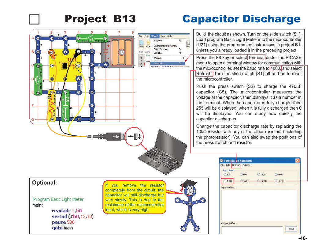
Project B13 Capacitor DischargeBuild the circuit as shown. Turn on the slide switch (S1).Load program Basic Light Meter into the microcontroller(U21) using the programming instructions in project B1,unless you already loaded it in the preceding project. Press the F8 key or select Terminal under the PICAXEmenu to open a terminal window for communication withthe microcontroller, set the baud rate to 4800, and selectRefresh. Turn the slide switch (S1) off and on to resetthe microcontroller. Push the press switch (S2) to charge the 470mFcapacitor (C5). The microcontroller measures thevoltage at the capacitor, then displays it as a number inthe Terminal. When the capacitor is fully charged then255 will be displayed, when it is fully discharged then 0will be displayed. You can study how quickly thecapacitor discharges. Change the capacitor discharge rate by replacing the10kW resistor with any of the other resistors (includingthe photoresistor). You can also swap the positions ofthe press switch and resistor.
Optional:
-46-
If you remove the resistorcompletely from the circuit, thecapacitor will still discharge butvery slowly. This is due to theresistance of the microcontrollerinput, which is very high.
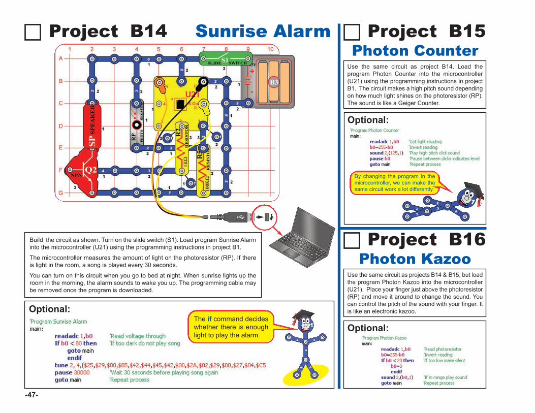
Optional:
Use the same circuit as projects B14 & B15, but loadthe program Photon Kazoo into the microcontroller(U21). Place your finger just above the photoresistor(RP) and move it around to change the sound. Youcan control the pitch of the sound with your finger. Itis like an electronic kazoo.
Project B16Photon Kazoo
-47-
Optional:
Project B15Photon Counter
Use the same circuit as project B14. Load theprogram Photon Counter into the microcontroller(U21) using the programming instructions in projectB1. The circuit makes a high pitch sound dependingon how much light shines on the photoresistor (RP).The sound is like a Geiger Counter.
By changing the program in themicrocontroller, we can make thesame circuit work a lot differently.
Project B14 Sunrise Alarm
Build the circuit as shown. Turn on the slide switch (S1). Load program Sunrise Alarminto the microcontroller (U21) using the programming instructions in project B1.
The microcontroller measures the amount of light on the photoresistor (RP). If thereis light in the room, a song is played every 30 seconds.
You can turn on this circuit when you go to bed at night. When sunrise lights up theroom in the morning, the alarm sounds to wake you up. The programming cable maybe removed once the program is downloaded.
Optional: The if command decideswhether there is enoughlight to play the alarm.
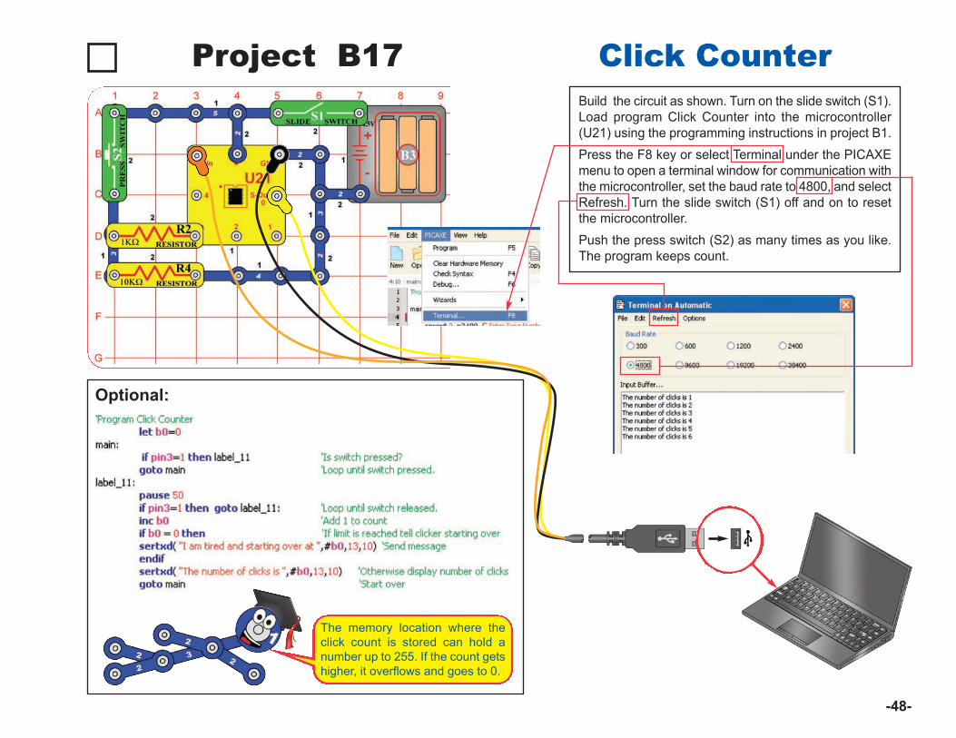
Project B17 Click CounterBuild the circuit as shown. Turn on the slide switch (S1).Load program Click Counter into the microcontroller(U21) using the programming instructions in project B1. Press the F8 key or select Terminal under the PICAXEmenu to open a terminal window for communication withthe microcontroller, set the baud rate to 4800, and selectRefresh. Turn the slide switch (S1) off and on to resetthe microcontroller. Push the press switch (S2) as many times as you like.The program keeps count.
Optional:
-48-
The memory location where theclick count is stored can hold anumber up to 255. If the count getshigher, it overflows and goes to 0.
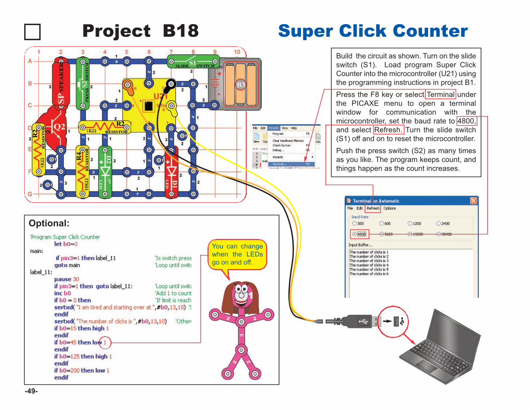
Project B18 Super Click CounterBuild the circuit as shown. Turn on the slideswitch (S1). Load program Super ClickCounter into the microcontroller (U21) usingthe programming instructions in project B1. Press the F8 key or select Terminal underthe PICAXE menu to open a terminalwindow for communication with themicrocontroller, set the baud rate to 4800,and select Refresh. Turn the slide switch(S1) off and on to reset the microcontroller. Push the press switch (S2) as many timesas you like. The program keeps count, andthings happen as the count increases.
Optional:
-49-
You can changewhen the LEDsgo on and off.
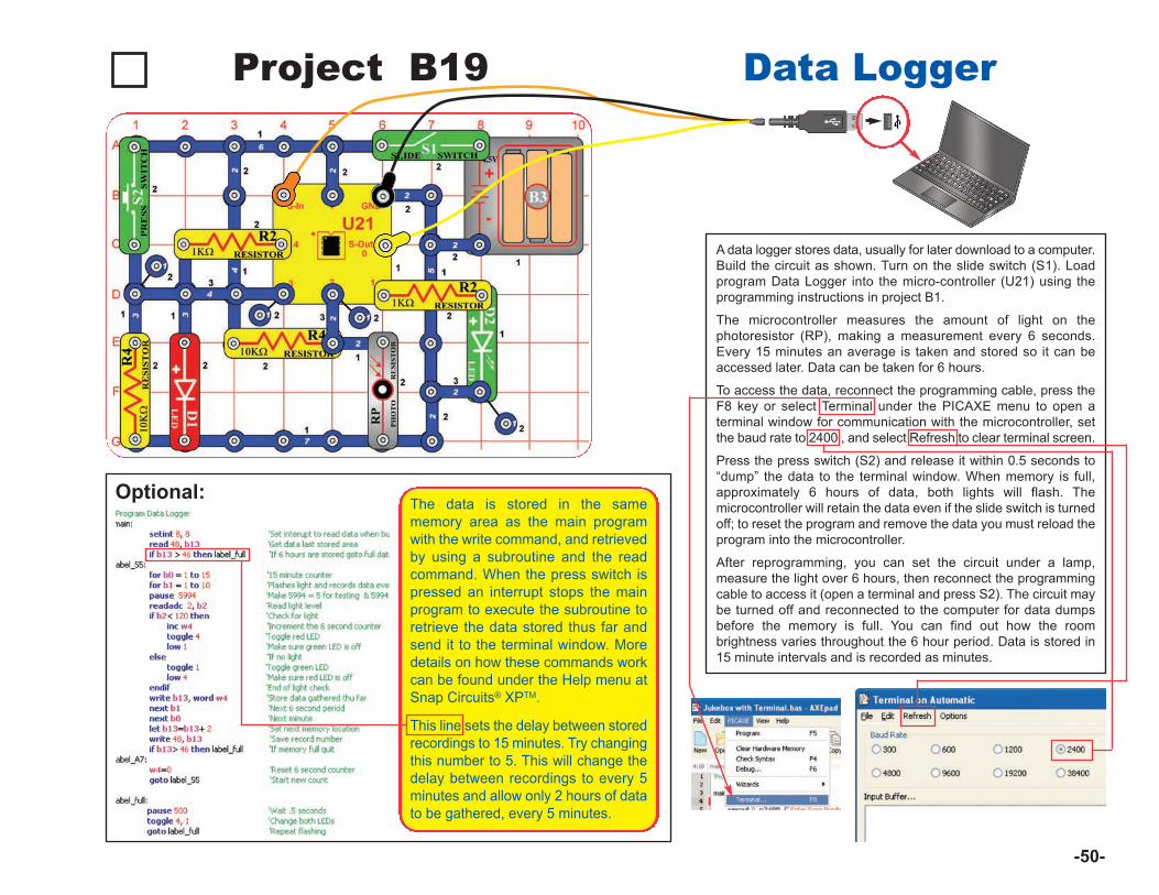
Project B19 Data Logger
A data logger stores data, usually for later download to a computer.Build the circuit as shown. Turn on the slide switch (S1). Loadprogram Data Logger into the micro-controller (U21) using theprogramming instructions in project B1.
The microcontroller measures the amount of light on thephotoresistor (RP), making a measurement every 6 seconds.Every 15 minutes an average is taken and stored so it can beaccessed later. Data can be taken for 6 hours.
To access the data, reconnect the programming cable, press theF8 key or select Terminal under the PICAXE menu to open aterminal window for communication with the microcontroller, setthe baud rate to 2400 , and select Refresh to clear terminal screen.
Press the press switch (S2) and release it within 0.5 seconds to“dump” the data to the terminal window. When memory is full,approximately 6 hours of data, both lights will flash. Themicrocontroller will retain the data even if the slide switch is turnedoff; to reset the program and remove the data you must reload theprogram into the microcontroller.
After reprogramming, you can set the circuit under a lamp,measure the light over 6 hours, then reconnect the programmingcable to access it (open a terminal and press S2). The circuit maybe turned off and reconnected to the computer for data dumpsbefore the memory is full. You can find out how the roombrightness varies throughout the 6 hour period. Data is stored in15 minute intervals and is recorded as minutes.
Optional:
-50-
The data is stored in the samememory area as the main programwith the write command, and retrievedby using a subroutine and the readcommand. When the press switch ispressed an interrupt stops the mainprogram to execute the subroutine toretrieve the data stored thus far andsend it to the terminal window. Moredetails on how these commands workcan be found under the Help menu atSnap Circuits® XPTM.
This line sets the delay between storedrecordings to 15 minutes. Try changingthis number to 5. This will change thedelay between recordings to every 5minutes and allow only 2 hours of datato be gathered, every 5 minutes.
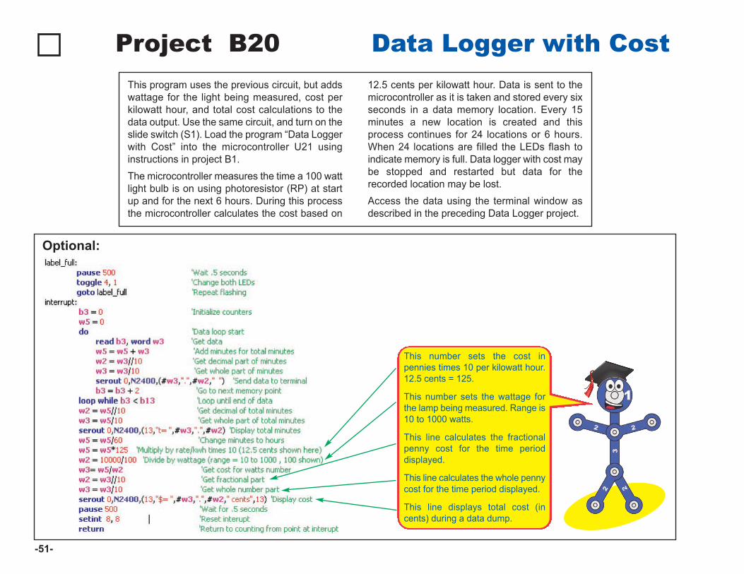
Project B20 Data Logger with CostThis program uses the previous circuit, but addswattage for the light being measured, cost perkilowatt hour, and total cost calculations to thedata output. Use the same circuit, and turn on theslide switch (S1). Load the program “Data Loggerwith Cost” into the microcontroller U21 usinginstructions in project B1. The microcontroller measures the time a 100 wattlight bulb is on using photoresistor (RP) at startup and for the next 6 hours. During this processthe microcontroller calculates the cost based on
12.5 cents per kilowatt hour. Data is sent to themicrocontroller as it is taken and stored every sixseconds in a data memory location. Every 15minutes a new location is created and thisprocess continues for 24 locations or 6 hours.When 24 locations are filled the LEDs flash toindicate memory is full. Data logger with cost maybe stopped and restarted but data for therecorded location may be lost.Access the data using the terminal window asdescribed in the preceding Data Logger project.
Optional:
-51-
This number sets the cost inpennies times 10 per kilowatt hour.12.5 cents = 125.
This number sets the wattage forthe lamp being measured. Range is10 to 1000 watts.
This line calculates the fractionalpenny cost for the time perioddisplayed.
This line calculates the whole pennycost for the time period displayed.
This line displays total cost (incents) during a data dump.
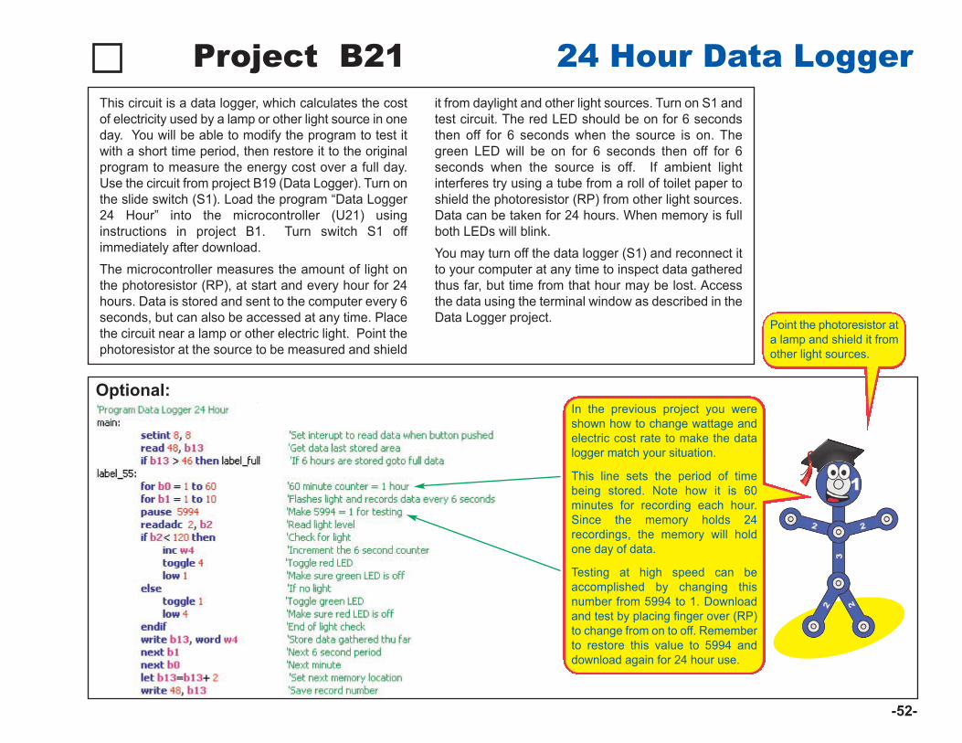
Project B21 24 Hour Data LoggerThis circuit is a data logger, which calculates the costof electricity used by a lamp or other light source in oneday. You will be able to modify the program to test itwith a short time period, then restore it to the originalprogram to measure the energy cost over a full day.Use the circuit from project B19 (Data Logger). Turn onthe slide switch (S1). Load the program “Data Logger24 Hour” into the microcontroller (U21) usinginstructions in project B1. Turn switch S1 offimmediately after download.The microcontroller measures the amount of light onthe photoresistor (RP), at start and every hour for 24hours. Data is stored and sent to the computer every 6seconds, but can also be accessed at any time. Placethe circuit near a lamp or other electric light. Point thephotoresistor at the source to be measured and shield
it from daylight and other light sources. Turn on S1 andtest circuit. The red LED should be on for 6 secondsthen off for 6 seconds when the source is on. Thegreen LED will be on for 6 seconds then off for 6seconds when the source is off. If ambient lightinterferes try using a tube from a roll of toilet paper toshield the photoresistor (RP) from other light sources.Data can be taken for 24 hours. When memory is fullboth LEDs will blink.You may turn off the data logger (S1) and reconnect itto your computer at any time to inspect data gatheredthus far, but time from that hour may be lost. Accessthe data using the terminal window as described in theData Logger project.
-52-
Optional: In the previous project you wereshown how to change wattage andelectric cost rate to make the datalogger match your situation.
This line sets the period of timebeing stored. Note how it is 60minutes for recording each hour.Since the memory holds 24recordings, the memory will holdone day of data.
Testing at high speed can beaccomplished by changing thisnumber from 5994 to 1. Downloadand test by placing finger over (RP)to change from on to off. Rememberto restore this value to 5994 anddownload again for 24 hour use.
Point the photoresistor ata lamp and shield it fromother light sources.
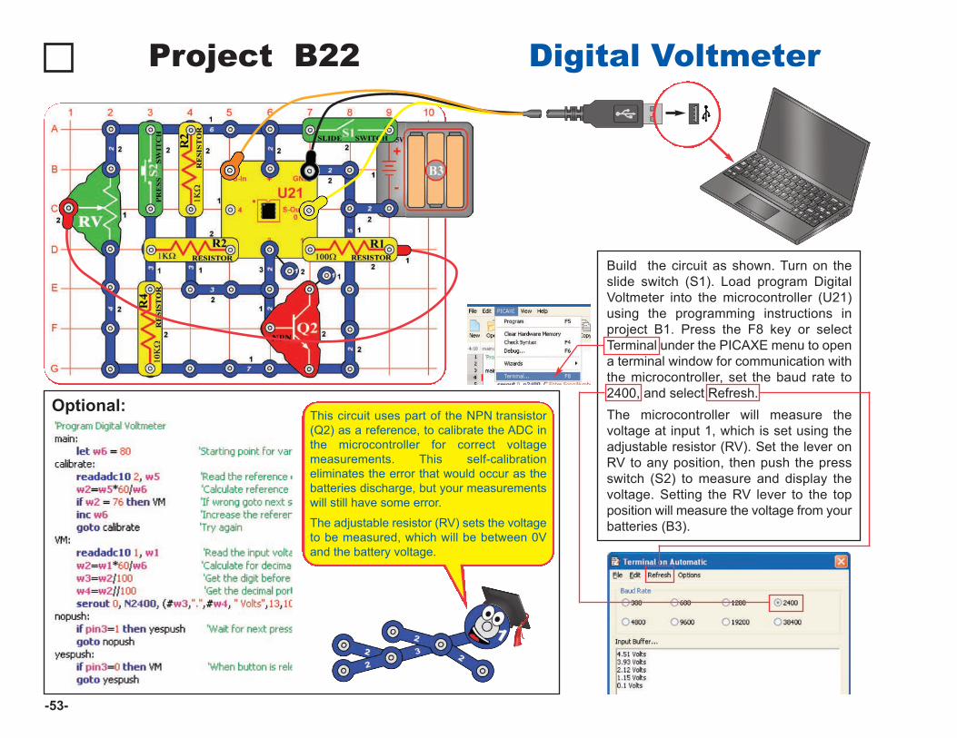
Project B22 Digital Voltmeter
Build the circuit as shown. Turn on theslide switch (S1). Load program DigitalVoltmeter into the microcontroller (U21)using the programming instructions inproject B1. Press the F8 key or selectTerminal under the PICAXE menu to opena terminal window for communication withthe microcontroller, set the baud rate to2400, and select Refresh. The microcontroller will measure thevoltage at input 1, which is set using theadjustable resistor (RV). Set the lever onRV to any position, then push the pressswitch (S2) to measure and display thevoltage. Setting the RV lever to the topposition will measure the voltage from yourbatteries (B3).
Optional:
-53-
This circuit uses part of the NPN transistor(Q2) as a reference, to calibrate the ADC inthe microcontroller for correct voltagemeasurements. This self-calibrationeliminates the error that would occur as thebatteries discharge, but your measurementswill still have some error.
The adjustable resistor (RV) sets the voltageto be measured, which will be between 0Vand the battery voltage.
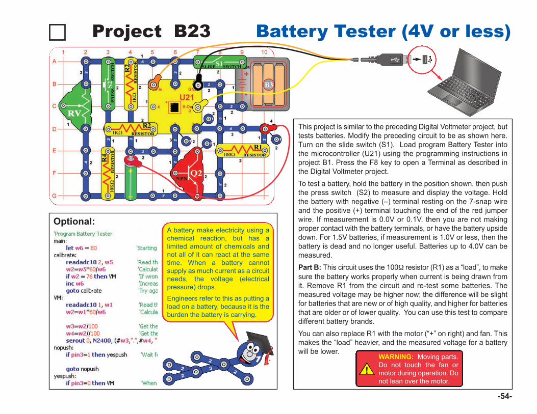
Project B23 Battery Tester (4V or less)
This project is similar to the preceding Digital Voltmeter project, buttests batteries. Modify the preceding circuit to be as shown here.Turn on the slide switch (S1). Load program Battery Tester intothe microcontroller (U21) using the programming instructions inproject B1. Press the F8 key to open a Terminal as described inthe Digital Voltmeter project. To test a battery, hold the battery in the position shown, then pushthe press switch (S2) to measure and display the voltage. Holdthe battery with negative (–) terminal resting on the 7-snap wireand the positive (+) terminal touching the end of the red jumperwire. If measurement is 0.0V or 0.1V, then you are not makingproper contact with the battery terminals, or have the battery upsidedown. For 1.5V batteries, if measurement is 1.0V or less, then thebattery is dead and no longer useful. Batteries up to 4.0V can bemeasured. Part B: This circuit uses the 100W resistor (R1) as a “load”, to makesure the battery works properly when current is being drawn fromit. Remove R1 from the circuit and re-test some batteries. Themeasured voltage may be higher now; the difference will be slightfor batteries that are new or of high quality, and higher for batteriesthat are older or of lower quality. You can use this test to comparedifferent battery brands. You can also replace R1 with the motor (“+” on right) and fan. Thismakes the “load” heavier, and the measured voltage for a batterywill be lower.
Optional:
!WARNING: Moving parts.Do not touch the fan ormotor during operation. Donot lean over the motor.
-54-
A battery make electricity using achemical reaction, but has alimited amount of chemicals andnot all of it can react at the sametime. When a battery cannotsupply as much current as a circuitneeds, the voltage (electricalpressure) drops.
Engineers refer to this as putting aload on a battery, because it is theburden the battery is carrying.
+
–
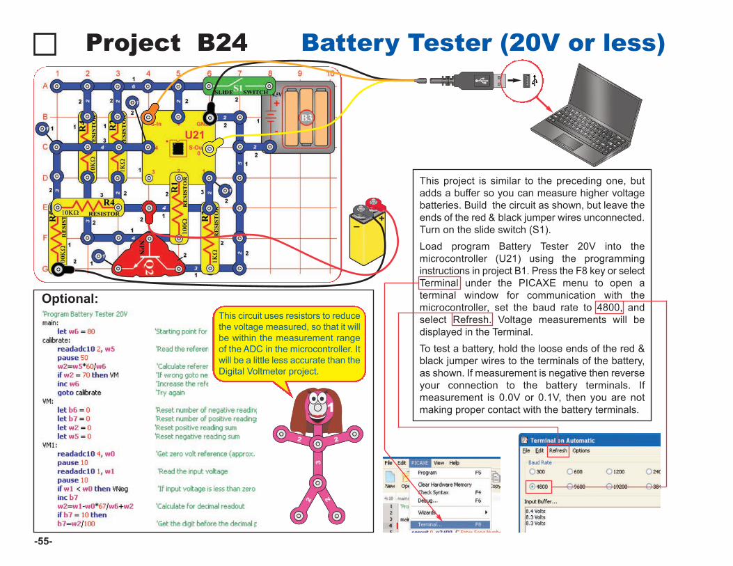
Project B24 Battery Tester (20V or less)
This project is similar to the preceding one, butadds a buffer so you can measure higher voltagebatteries. Build the circuit as shown, but leave theends of the red & black jumper wires unconnected.Turn on the slide switch (S1).Load program Battery Tester 20V into themicrocontroller (U21) using the programminginstructions in project B1. Press the F8 key or selectTerminal under the PICAXE menu to open aterminal window for communication with themicrocontroller, set the baud rate to 4800, andselect Refresh. Voltage measurements will bedisplayed in the Terminal.To test a battery, hold the loose ends of the red &black jumper wires to the terminals of the battery,as shown. If measurement is negative then reverseyour connection to the battery terminals. Ifmeasurement is 0.0V or 0.1V, then you are notmaking proper contact with the battery terminals.
Optional:
-55-
–+
This circuit uses resistors to reducethe voltage measured, so that it willbe within the measurement rangeof the ADC in the microcontroller. Itwill be a little less accurate than theDigital Voltmeter project.
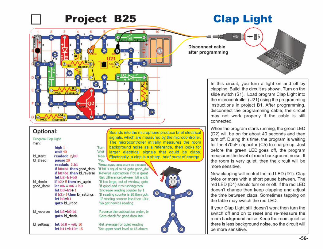
Project B25 Clap Light
In this circuit, you turn a light on and off byclapping. Build the circuit as shown. Turn on theslide switch (S1). Load program Clap Light intothe microcontroller (U21) using the programminginstructions in project B1. After programming,disconnect the programming cable; the circuitmay not work properly if the cable is stillconnected. When the program starts running, the green LED(D2) will be on for about 40 seconds and thenturn off. During this time, the program is waitingfor the 470mF capacitor (C5) to charge up. Justbefore the green LED goes off, the programmeasures the level of room background noise. Ifthe room is very quiet, then the circuit will bemore sensitive. Now clapping will control the red LED (D1). Claptwice or more with a short pause between. Thered LED (D1) should turn on or off. If the red LEDdoesn’t change then keep clapping and adjustthe time between claps. Sometimes tapping onthe table may switch the red LED. If your Clap Light still doesn’t work then turn theswitch off and on to reset and re-measure theroom background noise. Keep the room quiet sothere is less background noise, so the circuit willbe more sensitive.
Optional:
-56-
Sounds into the microphone produce brief electricalsignals, which are measured by the microcontroller.The microcontroller initially measures the roombackground noise as a reference, then looks forlarger electrical signals that could be claps.Electrically, a clap is a sharp, brief burst of energy.
Disconnect cableafter programming
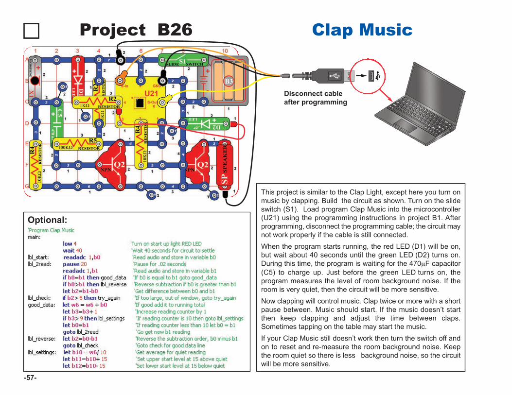
Project B26 Clap Music
This project is similar to the Clap Light, except here you turn onmusic by clapping. Build the circuit as shown. Turn on the slideswitch (S1). Load program Clap Music into the microcontroller(U21) using the programming instructions in project B1. Afterprogramming, disconnect the programming cable; the circuit maynot work properly if the cable is still connected.When the program starts running, the red LED (D1) will be on,but wait about 40 seconds until the green LED (D2) turns on.During this time, the program is waiting for the 470mF capacitor(C5) to charge up. Just before the green LED turns on, theprogram measures the level of room background noise. If theroom is very quiet, then the circuit will be more sensitive.Now clapping will control music. Clap twice or more with a shortpause between. Music should start. If the music doesn’t startthen keep clapping and adjust the time between claps.Sometimes tapping on the table may start the music.If your Clap Music still doesn’t work then turn the switch off andon to reset and re-measure the room background noise. Keepthe room quiet so there is less background noise, so the circuitwill be more sensitive.
Optional:
-57-
Disconnect cableafter programming
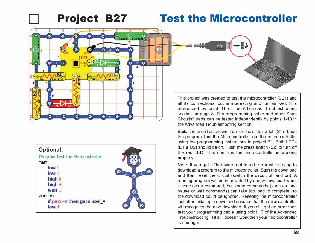
Project B27 Test the Microcontroller
This project was created to test the microcontroller (U21) andall its connections, but is interesting and fun as well. It isreferenced by point 11 of the Advanced Troubleshootingsection on page 8. The programming cable and other SnapCircuits® parts can be tested independently by points 1-10 inthe Advanced Troubleshooting section. Build the circuit as shown. Turn on the slide switch (S1). Loadthe program Test the Microcontroller into the microcontrollerusing the programming instructions in project B1. Both LEDs(D1 & D2) should be on. Push the press switch (S2) to turn offthe red LED. This confirms the microcontroller is workingproperly. Note: If you get a “hardware not found” error while trying todownload a program to the microcontroller: Start the downloadand then reset the circuit (switch the circuit off and on). Arunning program will be interrupted by a new download whenit executes a command, but some commands (such as longpause or wait commands) can take too long to complete, sothe download could be ignored. Reseting the microcontrollerjust after initiating a download ensures that the microcontrollerwill recognize the new download. If you still get an error thentest your programming cable using point 10 of the AdvancedTroubleshooting. If it still doesn’t work then your microcontrolleris damaged.
Optional:
-58-

Snap Circuits® XPTM is an introduction to what you can do withmicrocontrollers, such as the PICAXE® 08M2 IC that you havebeen using. This section is intended for users who would like todevelop their own programs for the microcontroller. Review theDO’s and DON’Ts of Building Circuits on page 8 beforeexperimenting on your own.
BASIC Programming: The programs you are using are written in a language called BASIC.BASIC (short for Beginner’s All-purpose Symbolic Instruction Code)is a language of symbolic commands, which will later be translatedinto coded instructions that the microcontroller can understand andexecute. The microcontroller you have can process about 1000BASIC commands a second.
You can download 80-220 lines of code in the microcontroller (thePICAXE® 08M2), depending on the commands used. OtherPICAXE® parts available can hold as much as 3200 lines of code.As programs become complex it is possible the micro-controller willrun out of memory to store the program. Most programs can bereduced in size by rewriting to use more subroutines. You can checkthe program length using ‘Syntax’.
A description of all the microcontroller commands and some basicprogramming techniques can be found under the Help menu atSnap Circuits® XPTM.
The PICAXE® Manual (Parts 1, 2, and 3) has more detailedexplanations of the PICAXE® commands, and other informationabout PICAXE® products, however much of this information isnot applicable to Snap Circuits® XPTM and some is very technical.The Snap Circuits® XPTM help file is customized to your product.
The PICAXE® Interface andProgramming SoftwareThe Snap Circuits® XPTM Editor makesdownloading programs to themicrocontroller easy. It also allows youto easily change parameters inprograms before downloading.However, we do not recommenddeveloping new programs with it,because more advanced editors areavailable with features like simulationand flowcharting.The microcontroller you are using hasa special programming interface thatmakes it easy to use. This interface,called PICAXE®, was developed byRevolution Education Ltd.. RevolutionEducation’s PICAXE® website,www.rev-ed.co.uk/picaxe, contains thefollowing:
● More information about PICAXE®
microcontrollers and software. Thisincludes information on the largerPICAXE® IC’s that are available, andwhere you may purchase them.
● Logicator: Logicator is moreadvanced software for programmingPICAXE® microcontrollers, includingyours. We recommend this as thebest software for young users whoare creating their own programs forthe microcontroller, due to its ease ofuse. Programs are created asgraphical flowcharts, not as typedBASIC programs. The flowchartsmake creating programs easy
because you select the commandsas symbols from menus, then selectthe parameters you need from a list.Flowcharts make it easy to see howdifferent parts of a program relate.With Logicator you can simulate aprogram to see how it will work,before downloading it into the micro-controller. Logicator is available onthe PICAXE® website as a freedownload. Further information and asample Logicator screen is on thenext page.
● Programming Editor: TheProgramming Editor is the mostadvanced software for programmingPICAXE® microcontrollers, includingyours. We recommend this as thebest software for advanced userswho are creating their own programsfor the microcontroller, due to itsrange of features. Programs arewritten in BASIC, but may also becreated as flowcharts (though theflowcharts here are not as easy touse as those in Logicator). AllPICAXE® features are supported.Great simulation tools, to help youtest complex programs beforedownloading them to themicrocontroller. The ProgrammingEditor is available on the PICAXE®
website as a free download. Most ofthe programs for Snap Circuits® XPTM
were created using the ProgrammingEditor. Further information and asample Programming Editor screenis on page 61.
-59-
PART C - To Go Further
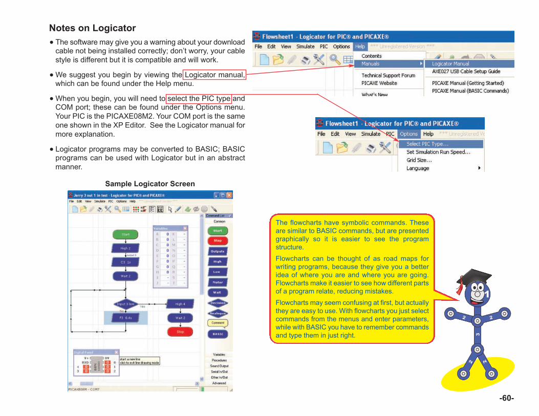
Notes on Logicator● The software may give you a warning about your download
cable not being installed correctly; don’t worry, your cablestyle is different but it is compatible and will work.
●We suggest you begin by viewing the Logicator manual,which can be found under the Help menu.
●When you begin, you will need to select the PIC type andCOM port; these can be found under the Options menu.Your PIC is the PICAXE08M2. Your COM port is the sameone shown in the XP Editor. See the Logicator manual formore explanation.
● Logicator programs may be converted to BASIC; BASICprograms can be used with Logicator but in an abstractmanner.
Sample Logicator Screen
-60-
The flowcharts have symbolic commands. Theseare similar to BASIC commands, but are presentedgraphically so it is easier to see the programstructure.
Flowcharts can be thought of as road maps forwriting programs, because they give you a betteridea of where you are and where you are going.Flowcharts make it easier to see how different partsof a program relate, reducing mistakes.
Flowcharts may seem confusing at first, but actuallythey are easy to use. With flowcharts you just selectcommands from the menus and enter parameters,while with BASIC you have to remember commandsand type them in just right.
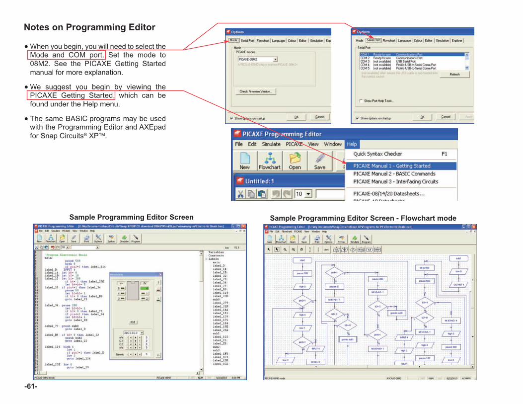
Notes on Programming Editor
●When you begin, you will need to select theMode and COM port. Set the mode to08M2. See the PICAXE Getting Startedmanual for more explanation.
●We suggest you begin by viewing thePICAXE Getting Started, which can befound under the Help menu.
● The same BASIC programs may be usedwith the Programming Editor and AXEpadfor Snap Circuits® XPTM.
Sample Programming Editor Screen - Flowchart modeSample Programming Editor Screen
-61-
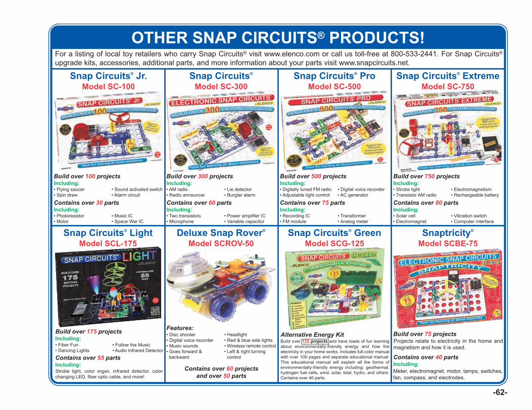
-62-
For a listing of local toy retailers who carry Snap Circuits® visit www.elenco.com or call us toll-free at 800-533-2441. For Snap Circuits®
upgrade kits, accessories, additional parts, and more information about your parts visit www.snapcircuits.net.
Build over 100 projectsIncluding:
Snap Circuits® Jr.Model SC-100
• Flying saucer• Spin draw
• Sound activated switch• Alarm circuit
Contains over 30 partsIncluding:• Photoresistor• Motor
• Music IC• Space War IC
Build over 300 projectsIncluding:
Snap Circuits®
Model SC-300
• AM radio• Radio announcer
• Lie detector• Burglar alarm
Contains over 60 partsIncluding:• Two transistors• Microphone
• Power amplifier IC• Variable capacitor
Build over 500 projectsIncluding:
Snap Circuits® ProModel SC-500
• Digitally tuned FM radio• Adjustable light control
• Digital voice recorder• AC generator
Contains over 75 partsIncluding:• Recording IC• FM module
• Transformer• Analog meter
Build over 750 projectsIncluding:
Snap Circuits® ExtremeModel SC-750
• Strobe light• Transistor AM radio
• Electromagnetism• Rechargeable battery
Contains over 80 partsIncluding:• Solar cell• Electromagnet
• Vibration switch• Computer interface
Snap Circuits® GreenModel SCG-125
Build over 75 projectsProjects relate to electricity in the home andmagnetism and how it is used.
Snaptricity®
Model SCBE-75
Contains over 40 partsIncluding:Meter, electromagnet, motor, lamps, switches,fan, compass, and electrodes.
Alternative Energy KitBuild over 125 projects and have loads of fun learningabout environmentally-friendly energy and how theelectricity in your home works. Includes full-color manualwith over 100 pages and separate educational manual.This educational manual will explain all the forms ofenvironmentally-friendly energy including: geothermal,hydrogen fuel cells, wind, solar, tidal, hydro, and others.Contains over 40 parts.
Deluxe Snap Rover®
Model SCROV-50
Features:• Disc shooter• Digital voice recorder• Music sounds• Goes forward &backward
• Headlight• Red & blue side lights• Wireless remote control• Left & right turning control
Contains over 60 projectsand over 50 parts
Snap Circuits® LightModel SCL-175
Build over 175 projectsIncluding:
Contains over 55 partsIncluding:Strobe light, color organ, infrared detector, colorchanging LED, fiber optic cable, and more!
• Fiber Fun• Dancing Lights
• Follow the Music• Audio Infrared Detector
OTHER SNAP CIRCUITS® PRODUCTS!
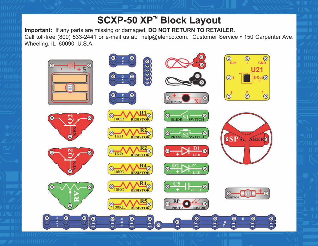
SCXP-50 XPTM Block LayoutImportant: If any parts are missing or damaged, DO NOT RETURN TO RETAILER.Call toll-free (800) 533-2441 or e-mail us at: [email protected]. Customer Service • 150 Carpenter Ave.Wheeling, IL 60090 U.S.A.
Related Documents