REUSE: A Combined Routing and Link Scheduling Mechanism for Wireless Mesh Networks Carlos Henrique Pereira Augusto and Celso Barbosa Carvalho and Marcel William Rocha da Silva and Jos´ e Ferreira de Rezende Grupo de Teleinform´atica e Automa¸ c˜ao Universidade Federal do Rio de Janeiro (UFRJ) P.O. Box 68.504 – Rio de Janeiro, RJ 21.941–972 Emails: {chenrique,celso,marcel,rezende}@gta.ufrj.br Abstract Increasing the capacity of wireless mesh networks has motivated numerous studies. In this context, the cross-layer optimization techniques involving joint use of routing and link scheduling are able to provide better capacity improvements. Most works in the literature propose linear programming models to combine both mechanisms. However, this approach has high computational complexity and cannot be extended to large-scale networks. Alternatively, algorithmic solutions are less complex and can obtain capacity values close to the optimal. Thus, we propose the REUSE algorithm, which combines routing and link scheduling and aims to increase throughput capacity in wireless mesh networks. Through simulations, the performance of the proposal is compared to a developed linear programming model, which provides optimal results, and to other proposed mechanisms in the literature that also deal with the problem algorithmically. We observed higher values of capacity in favor of our proposal when compared to the benchmark algorithms. Keywords: wireless networks, mesh, link scheduling, routing 1. Introduction The study of the capacity of wireless mesh net- works (WMNs) has received a great deal of at- tention in the last years [1, 2, 3, 4, 5, 6]. These works show that the capacity of WMNs depends on several factors such as nodes density and place- ment, and traffic demand. Gupta and Kumar [1] show that the throughput per node is given by Θ( 1 √ n log n ), assuming arbitrary communication pattern between pairs of n identical and randomly placed nodes. Following this fundamental work, different models for a variety of scenarios were proposed to estimate the capacity of WMNs [7, 8]. A methodology commonly used on these works to calculate bounds for the network capacity as- sumes that link scheduling occurs in slots of time, where links that do not present mutual interfer- ence may be activated at the same time slot. Hence, optimal link scheduling algorithms aim to deter- mine the links that will be activated in each time slot in such a way that all links of the network are scheduled at least once in a certain minimum number of slots. When used as the TDMA sched- ule, this minimum sequence of slots corresponds to the maximum capacity of network under asymp- totic traffic conditions. Thus, the goal is to mini- mize TDMA schedule length in order to maximize capacity. On the other hand, this same TDMA schedule length designates the maximum through- put that can be achieved under a certain traffic demand matrix. In this case, only the links with traffic demand should be scheduled. The works in [2, 9, 3, 10, 4, 11, 12, 5, 13, 14, 6] follow this approach. Preprint submitted to Computer Communications October 30, 2011

Welcome message from author
This document is posted to help you gain knowledge. Please leave a comment to let me know what you think about it! Share it to your friends and learn new things together.
Transcript
REUSE: A Combined Routing and Link Scheduling Mechanism for
Wireless Mesh Networks
Carlos Henrique Pereira Augusto and Celso Barbosa Carvalho and Marcel William Rocha da Silvaand Jose Ferreira de Rezende
Grupo de Teleinformatica e AutomacaoUniversidade Federal do Rio de Janeiro (UFRJ)
P.O. Box 68.504 – Rio de Janeiro, RJ 21.941–972Emails: {chenrique,celso,marcel,rezende}@gta.ufrj.br
Abstract
Increasing the capacity of wireless mesh networks has motivated numerous studies. In this context, thecross-layer optimization techniques involving joint use of routing and link scheduling are able to providebetter capacity improvements. Most works in the literature propose linear programming models tocombine both mechanisms. However, this approach has high computational complexity and cannot beextended to large-scale networks. Alternatively, algorithmic solutions are less complex and can obtaincapacity values close to the optimal. Thus, we propose the REUSE algorithm, which combines routingand link scheduling and aims to increase throughput capacity in wireless mesh networks. Throughsimulations, the performance of the proposal is compared to a developed linear programming model,which provides optimal results, and to other proposed mechanisms in the literature that also deal withthe problem algorithmically. We observed higher values of capacity in favor of our proposal whencompared to the benchmark algorithms.
Keywords: wireless networks, mesh, link scheduling, routing
1. Introduction
The study of the capacity of wireless mesh net-works (WMNs) has received a great deal of at-tention in the last years [1, 2, 3, 4, 5, 6]. Theseworks show that the capacity of WMNs dependson several factors such as nodes density and place-ment, and traffic demand. Gupta and Kumar[1] show that the throughput per node is givenby Θ( 1√
n logn), assuming arbitrary communication
pattern between pairs of n identical and randomlyplaced nodes. Following this fundamental work,different models for a variety of scenarios wereproposed to estimate the capacity of WMNs [7, 8].
A methodology commonly used on these worksto calculate bounds for the network capacity as-sumes that link scheduling occurs in slots of time,where links that do not present mutual interfer-
ence may be activated at the same time slot. Hence,optimal link scheduling algorithms aim to deter-mine the links that will be activated in each timeslot in such a way that all links of the networkare scheduled at least once in a certain minimumnumber of slots. When used as the TDMA sched-ule, this minimum sequence of slots correspondsto the maximum capacity of network under asymp-totic traffic conditions. Thus, the goal is to mini-mize TDMA schedule length in order to maximizecapacity. On the other hand, this same TDMAschedule length designates the maximum through-put that can be achieved under a certain trafficdemand matrix. In this case, only the links withtraffic demand should be scheduled. The worksin [2, 9, 3, 10, 4, 11, 12, 5, 13, 14, 6] follow thisapproach.
Preprint submitted to Computer Communications October 30, 2011
Some of these works [2, 3, 10, 12, 5, 13, 14] in-tegrate routing and link scheduling in order to ob-tain improved performance bounds. These worksdefine how links should be scheduled and whichroutes should be chosen to meet a certain traf-fic demand in a minimum time. They show thatthe combined use of routing and link schedulingmechanisms provides a better performance thanthe independent use of them.
The idea of coupling these mechanisms comesfrom the fact that one can select routes that suf-fer and cause less interference, and hence, favorthe simultaneity in their links activation. The in-tegrated mechanisms look for a balance betweenchoosing longer routes, which are less prone to in-terference, but have more links to be scheduled,and selecting shorter routes with fewer links thatsuffer a larger interference. Conversely, routinghas a great impact in the link scheduling sincemulti-hop paths followed by traffic flows deter-mine the links of the network that need to beactivated and their respective demand. Normally,scheduling algorithms deal with this increased de-mand by assigning weights to links that are tra-versed by traffic flows.
However, the joint optimization, named cross-layer, of routing and link scheduling mechanismspresented in most of these works uses the lin-ear programming optimization approach to ob-tain performance bounds. Therefore, there arefew works that follow an algorithmic approach topropose combined link scheduling and routing al-gorithms [13, 14]. The algorithm proposed in thispaper follows this approach.
At first, this paper evaluates the impact of theroutes used by multi-hop flows in WMNs in theperformance of link scheduling algorithms. Fol-lowing, a joint mechanism of routing and schedul-ing, called REUSE, that explores the spatial reuseby favoring the simultaneity in links activation isproposed. This mechanism defines both a routingmetric and a scheduling algorithm in which thetraffic demand and the allowed degree of interfer-ence among links have been taken into account.
The main contributions of this paper are two-fold, the proposal of the REUSE algorithm, whichcombines routing and link scheduling, and its eval-
uation and comparison to other proposals and tothe joint optimization through linear program-ming of both mechanisms. The obtained resultsshow the efficiency of the mechanism in compar-ison to other three algorithms [4, 6, 15], two ofwhich schedule links traversed by shortest pathflows [4, 6] and a third one that performs inte-grated routing and link scheduling [15].
This paper is organized as follows. The nextsection presents related works. Section 3 describesthe proposed mechanism. In Section 4, the simu-lation environment, the models used in the perfor-mance evaluation of the algorithms, and the prob-lem formulation through linear programming aredetailed. Section 5 shows the numerical resultsobtained through simulation and linear program-ming optimization as well as a discussion aboutthem. Finally, Section 7 draws the conclusions.
2. Related Work
The problem of link scheduling in wireless net-works has been tackled for a long time [16, 9, 10,17, 4, 15, 12, 11, 5, 6, 18, 14]. These works addressthe problem in an isolated fashion [9, 10, 4] orjointly with routing and topology/power control[16, 17, 15, 5, 12]. According to the used method-ology, existing works can be classified as follows:i) optimization by linear/integer programming [17];ii) graphs coloring [19, 12] iii) approximation algo-rithms [4, 6]; iv) other (neural networks, geneticalgorithms, heuristics, etc.) [16, 15, 11]. Concern-ing the interference model, these studies use theprotocol (or UDG) [9, 12] or physical (or SINR)models [4]. In most cases, algorithms/heuristicsare centralized and require global topology knowl-edge and/or information about links’ interferencelevels. However, some studies propose distributedalgorithms [19, 12] based on graph coloring.
A work similar to ours is presented in [14].The authors propose the use of multipath routing,where each one of the paths followed by a certainflow is sequentially chosen by using a metric thattakes into account the scheduling of the links tra-versed by the previous path. The results of theirheuristic are compared to the optimal value ob-tained by solving an optimization problem that
2
takes into account both routing and scheduling.However, the authors do not compare their resultsto others in the literature.
By modeling the wireless network as a graph,the scheduling problem can be translated into agraph coloring problem [19, 3, 12]. This coloringcan be made both on edges (edge-coloring) and onvertices (vertex-coloring). In the first case, thecoloring is valid if all incident edges of a vertexhave distinct colors. This coloring can be easilymapped to a TDMA scheduling, where each edgerepresents a communication link and each colorcorresponds to a TDMA slot. Edges that receivethe same color correspond to links that can beactivated in the same slot. The disadvantage ofedge coloring is that despite of ensuring that thereare no primary conflicts in scheduling1, it does notguarantee that there are no collisions caused bymutual interference due to the activation of twoor more links that share the same color.
To overcome this problem, the work in [3] in-troduces the concept of conflict graph, whose ver-tices correspond to communication links and anedge between two vertices exists if the two linkscannot be simultaneously activated. Therefore, itis possible to create edges in the conflict graphthat represent the mutual interference betweenlinks for a given interference model. Thus, whencoloring the vertices of the conflict graph, whichestablishes that any two adjacent vertices mustreceive distinct colors, conflicts caused by sched-uling interference are avoided. In summary, theproblem of interference-free scheduling of links con-sists on determining the minimum number of col-ors necessary to color the vertices of the conflictgraph. The work in [12] proposes several algo-rithms, both centralized and distributed, to thecoloring problem.
The next three subsections detail the threealgorithms that have been used as comparisonbasis to the proposed one. The first one, theLDF (Lesser Distance First) algorithm [6], waschosen due to its ability to provide the upper-
1Occurrence in the same slot of simultaneous trans-mission and reception at the same node or recep-tion/transmission to/from two or more nodes
bound capacity of arbitrary networks. Also, theauthors prove that the algorithm approximates tothe optimum solution within a factor ofO(log(n)),where n is the number of links. The second algo-rithm, GreedyPhy, deals with heterogeneous traf-fic demands, presents good performance and wasused as basis for our proposal. The third algo-rithm, IRMA, is the most similar to ours sinceit defines integrated routing and MAC schedulingalgorithms.
2.1. LDF Algorithm
The work in [6] presents a centralized sched-uling algorithm that determines the throughputcapacity of arbitrary networks. It employs theSINR interference model together with a geomet-ric analysis. The objectives of the algorithm areto maximize the amount of links scheduled con-currently in a slot and to schedule all links in thesmallest amount of slots.
The algorithm chooses from a set L = {l1, ..., ln}of links to be scheduled the smaller link lv oflength dvv (Euclidean distance between source svand receiver rv). After lv is added to slot s1 ofset S = {s1, ..., sT}, the SINR restriction guaran-tee is performed in two steps. First, every linklu that is within a radius c · dvv of the receiverrv is removed from the set L, where c is a con-stant determined by geometric calculations anddepends on the SINR required by link lv and onthe average path loss exponent. In the secondstep, all remaining links that have affectednessgreater than or equal to 2/3 are also removed fromthe set L. The affectedness of a link lw measureshow this link is affected by transmission of otherslinks already present in one slot and is given byAS(lw) = β(
∑lv∈S Ivw + N)/Pww. In this equa-
tion, β is the SINR required by link lw, Ivw is thetotal interference within one slot of set S, causedby all transmitters sv in the receiver rw, N is thebackground noise power and Pww is the receivedpower in receiver rw from transmitter sw. Thealgorithm is executed repeatedly, taking as inputL = L \ St (t = 1, ..., T ), until all links of set Lhave been scheduled.
3
2.2. GreedyPhy Algorithm
The work in [4] proposes a centralized algo-rithm, called GreedyPhysical, which employs theSINR interference model and a conflict graph thatmodels each edge as a vertex. Each edge has aweight representing the signal strength receivedby other vertices. The idea is used to calculate theinterference that each node causes over all otherswhile it is transmitting.
The first step of the algorithm to calculatethe schedule SPhy is to determine the interfer-ence number of each link, and sort those linksin decreasing order of interference number. Theinterference number of a link e = (u, v) is thenumber of links ei that do not own vertex u orv, and cannot be simultaneously scheduled with edue to interference. After ordering them, links aregreedily scheduled in the first possible slots. Todetermine whether it is possible to schedule ei inslot tk the algorithm checks if the power added byei in each link already scheduled in that slot doesnot exceed the required SINR threshold. Also, thesum of the power of all transmissions previouslyscheduled should not exceed the same thresholdat ei. If existing slots are not sufficient to allo-cate all transmissions of ei, new slots are addedto the end of the SPhy schedule. The remainingtransmissions of ei are scheduled alone in theseslots.
2.3. IRMA Algorithm
The work in [15] proposes centralized algo-rithms to jointly select paths to be followed by theflows and to set up end-to-end TDMA schedules.In [13], the same authors provide distributed algo-rithms for the same problem. For path selection,an SPF algorithm is used, where the cost of eachlink is updated with the number of already allo-cated slots plus blocked slots. Then, min-hop andbandwidth-aware algorithms are used to calculatethe path for the flow. Once the path is selected,the TDMA schedule for each link along the pathis updated to account for the allocation of slotsrequired by this new flow. Also, those links whichcannot be concurrently scheduled with these linkshave their respective slots blocked. To determinewhich links cannot be simultaneously scheduled
within the allocated slots, IRMA uses an n-hopneighborhood interference model.
The n-hop neighborhood interference model isderived from the protocol-based interference mo-del, where distance-based constraints are substi-tuted by hop-based ones. The model states thatany node k within the n-hop neighborhood of theintended receiver must be not transmitting. Thus,n is used as interference index instead of the inter-ference range. Let α and SINRthresh be the pathloss exponent and the minimum required SINRin order to successfully decode a packet, respec-tively, then n should be the first integer that sat-isfies n >= α
√SINRthresh [15]. Due to the use
of this interference model, IRMA does not guar-antee an interference-free schedule, i.e. collisionsmay occur in some slots. For this algorithm becompared to the others, which are interference-free, we choose n as the first integer that sat-isfies the equation above but that also providesan interference-free schedule, i.e. we increase thevalue of n until this is achieved.
3. Proposed Mechanism
The proposed mechanism, named REUSE, isbased on the use of a routing metric that favorsspatial reuse, and of a scheduling algorithm thatincreases the number of simultaneous activatedlinks. Next, the REUSE mechanism and the as-sumptions used in its distributed design are de-scribed.
3.1. REUSE Mechanism
The REUSE is composed of two mechanismsfor routing and link scheduling, which were spe-cially designed to work together aiming to obtaina cross-layer optimization. The routing mech-anism consists of a new metric, which assumesthe use of an SPF algorithm, while the proposedscheduling algorithm is an extended version of theGreedyPhy [4], which is described in Section 2.2,with the purpose of coupling it with the routing.Although the separate operation of both mech-anisms is straightforward in its objectives, theirjoint operation is the main contribution of theREUSE mechanism.
4
The extensions to the GreedyPhy algorithmconcern the calculation of the interference numberof each link. In our proposal, this value is calcu-lated by multiplying the traffic demand of the linkby the number of links with which it cannot besimultaneously scheduled since they cause mutualinterference. Moreover, only links that have sometraffic demand are counted as interfering links,instead of all links as in the original algorithm.However, as said before, the traffic demand im-posed on links depends on routes chosen by flows.By doing this extension, a coupling between rout-ing and link scheduling is created, which meansthat the choice of routes has an impact on howlinks will be scheduled, i.e. a joint mechanism isdesigned. Considering a network where all trafficflows from multiple sources to a unique sink, theintuition behind this extension is related to thefact that links to/from the sink (or gateway) areusually the most demanding, and then should bescheduled with priority.
The reasoning behind the routing metric isto balance traffic across the network, increasingthe weight of links around routes used by flowsaccording to the level of interference that is al-lowed. This load balancing favors simultaneouslink schedules, increasing spatial reuse and, hence,the network capacity.
In the beginning, all links have their weightsset to 1, which are modified as new flows enter orleave the network. We assume the following setsof nodes and links:
• Ni - set of nodes traversed by the flow i;
• Ri - set of links traversed by the flow i;
• Vi - set of one-hop neighboring nodes of nodesthat belong to Ni;
• E(X) - set of all incident links to nodes ofthe set X.
The weight of link j assumes a new value w′j given
by:
w′j =
wj ± α ∀j ∈ Ri;wj ± β ∀j ∈ E(Ni) | j /∈ Ri;wj ± γ ∀j ∈ E(Vi) | j /∈ E(Ni).
(1)
Where wj is the previous weight of the link j, andα, β, and γ should be set according to the follow-ing reasoning. Firstly, these parameters shouldassume values of the same order of magnitude ofthe initial weight since SPF depends on relativeweight values. In the case where these parame-ters are much smaller than the initial weight, theywill not influence route calculations. In contrast,if set too large they can completely exclude linksalready used, and hence create stretched routes,which require lengthy scheduling. Moreover, it isintuitive to have α > β > γ since their objectiveis to discourage the use of: i) firstly, the links tra-versed by the flow; ii) followed by the links relatedto the nodes traversed by the flow; iii) and finally,the links related to the one-hop neighbor nodes ofthe nodes traversed by the flow.
Another important issue regarding α, β andγ calculation is the susceptibility of close linksto suffer interference. This can be measured bythe SINRthresh, i.e. the minimum signal-to-noiseratio (in dB) required to decode a packet at thetransmission rate used by link j. For this purposewe define the equation 2.
r = 1 +(SINRthresh −minSINR)
(maxSINR−minSINR)(2)
Equation 2 provides values between [1, 2] forSINRthresh in the range of 5 (minSINR) to 30(maxSINR) dB, which roughly corresponds tothe SINR values required to successfully decodeframes transmitted at 2 Mbps and 54 Mbps ratesin the 802.11g, respectively. The higher the valueof SINRthresh, the higher are the weights assigned.Thus, one can describe α, β and γ as 1 ∗ r, 1/2 ∗ rand 1/4 ∗ r, respectively.
The intuition behind the definition of param-eter r (Equation 2) used in the α, β and γ cal-culation is that links are more susceptible to in-terference in scenarios where higher transmission
5
(a) First route (src=1,dst=16)
(b) Second route (src=5,dst=16)
(c) Third route (src=2,dst=16)
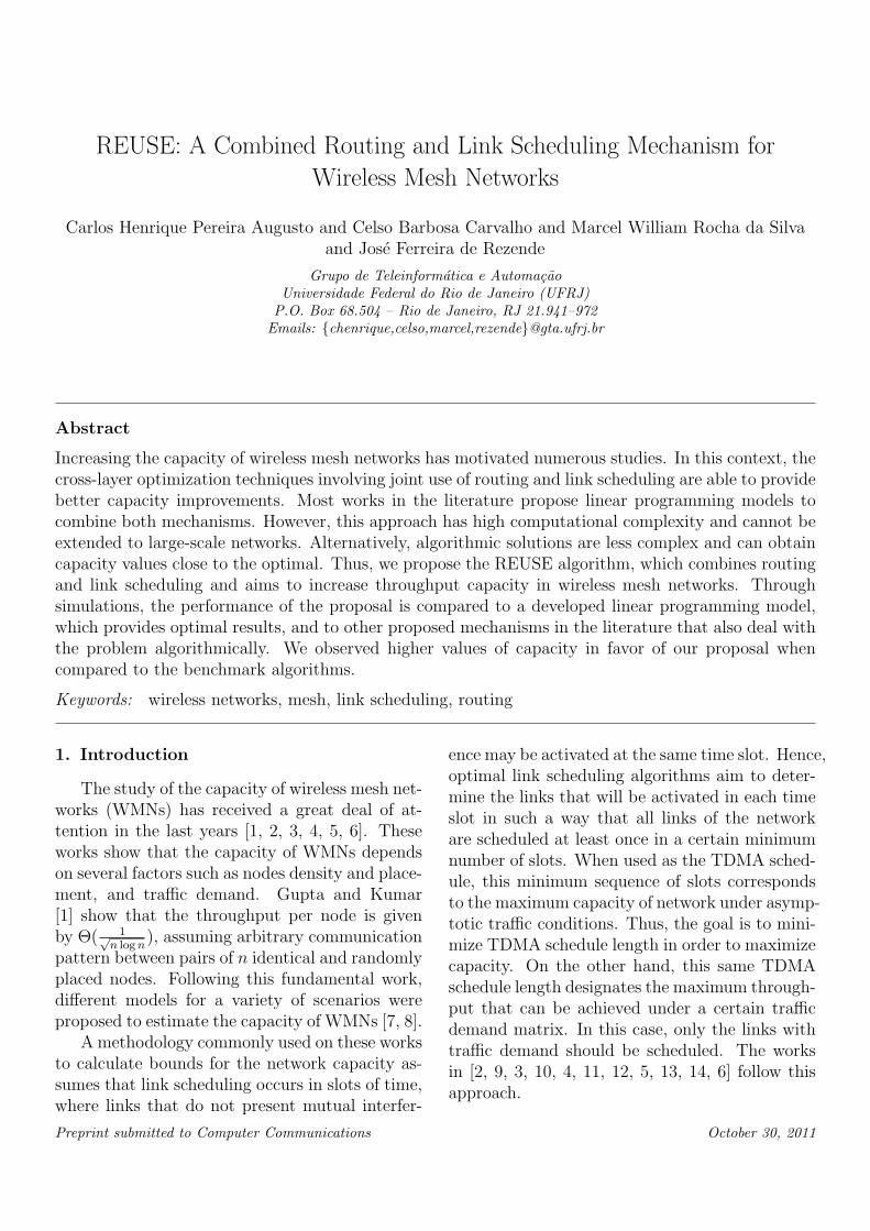
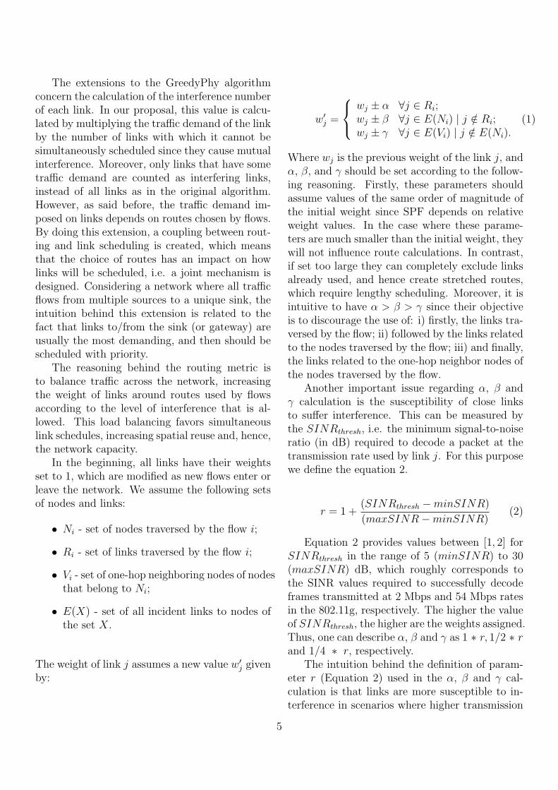
Figure 1: Three consecutive routes created by the pro-posed routing metric.
rates are used. Therefore, the higher values ofSINRthresh needed to decode packets transmit-ted at higher rates result in an increased r, andhence in higher values for α, β and γ. By doingso, a better spatial spreading of future calculatedroutes is expected, which favors simultaneity oflinks scheduling.
Once new weights are determined, the routeto be followed by a new admitted flow must bethe one with lowest cost calculated by the SPFalgorithm. The sign ± in the Equation 1 indicates
that the value of wj should be increased (+ sign)at the arrival of a new flow and decreased (− sign)when a flow leaves the network.
Figure 1 exemplifies the sequential establish-ment of three routes from source nodes 1, 5 and2 to destination node 16 in a grid topology un-der the proposed routing metric. The subfiguresshow the paths taken by each route (indicated bythe boldest lines) and the updated link weightsafter each route creation. The start of each flowincreases the weights of links closer to the selectedpath by the parameters α, β and γ. The SPF algo-rithm tends to select new paths that pass throughlowest cost links, which are farther from the previ-ously created ones. This way, the proposed metricpromotes spatial spreading of routes, which favorsposterior link scheduling.
3.2. Distributed Design Assumptions
The REUSE mechanism assumes a central-ized approach with global information knowledge.However, we argue that a distributed algorithmcould be developed. In the following, some con-siderations in defining this algorithm are given.Let a multi-hop wireless network be modeled as adirected graph G(V,E) composed of a vertex setV = {v1, v2, ..., vn}, n = 1, ..., |V | that representswireless nodes and a edge set E = {e1,2, ..., ei,j},i, j = 1, ..., |E| that denotes communication links.
Assuming a global knowledge of all nodes posi-tioning, propagation model and transmission power,each node vi ∈ V can determine a power matrixPr, where each element pjk contains the recep-tion power at node vk from node vj for j, k =1, 2, ..., n. By using this matrix along with thetopology graph, each node can calculate inter-ference numbers. However, with the purpose ofavoiding making strong assumptions about prop-agation models, a new approach is described next.
Considering a distributed algorithm that as-signs globally unique and ordered integer num-bers to nodes (nodeID) [20], a sequence of mini-slots can be used with the aim of each node vito obtain its power vector, i.e. the ith row ofthe power matrix Pr. During this sequence, eachnode transmits a tone in the mini-slot match-ing its nodeID. Assuming a conflict-free schedule
6
and global knowledge of nodeIDs, each node cancalculate its own power vector. After floodingtheir power vector, nodes can calculate interfer-ence numbers for all links.
However, interference numbers calculated bythe method above do not take into account thetraffic demand of each link. In order to estimatethis, each node keeps track of the number of activeflows and their respective demand for each outgo-ing link. By piggybacking this information on linkstate advertisements, each node can locally calcu-late interference numbers, rank links by this value,and calculate respective schedules. Link weightsare also updated by using this flooded informationaccording to equation 1.
In the next section, the interference and prop-agation models used in the system evaluation aredetailed. Also, some details of the simulator usedin this assessment are provided. Next, the LPformulation of the problem is presented.
4. Models, Simulation Environment and LPOptimization
To determine the links that do not interfereand therefore can be simultaneously activated, aninterference model should be used. Two modelsare widely used: physical (or SINR) and proto-col (or UDG). The first determines whether thesignal-to-interference+noise ratio (SINR) is greaterthan a certain threshold so that the transmit-ted signal can be decoded with a certain bit er-ror rate (BER) [18]. The protocol model estab-lishes that a successful transmission occurs whena node is within the transmission range of theintended transmitter and away from interferencerange from others. In this second model, thegreatest difficulty is to determine the proper inter-ference range. The work in [18] shows that, witha good choice of this value, both models lead tothe same results, and the protocol model is muchsimpler computationally.
In this study, the simulations consider the phys-ical interference model (or SINR) associated withthe log-distance path loss model to determine thefeasibility in the concurrent activation of links.The physical model establishes that the probabil-
ity of a successful packet reception is equal to 1 ifthe SINR is above a certain threshold (SINRthresh).Equation 3 shows the necessary condition for suc-cessful packet reception, where Pt
i is the signalpower of the intended transmitter i and gij is thepath loss from node i to node j on link ei,j. Thedenominator corresponds to the noise N added tothe signal power that arrives at node j issued byall possible interfering node k with k ∈ N, k = i,k = 1, ..., |K|, where K is the set of all transmiterk that interferes in the receiver j of the link eij.In this model, the simultaneous scheduling of aset of links is considered valid (or feasible) if alltransmissions do not suffer interference that cancause loss of transmitted packets.
Pti ∗ gij∑
k =i Ptk ∗ gkj +N
≥ SINRthresh (3)
The log-distance path loss model provides theaverage received signal power (Pr), given by Pt∗γ
dα,
where Pt is the transmission power. The path lossfactor α reflects the influence of the environment,d is the distance between transmitter and receiverand γ factor takes into account the influence of thefrequency, antenna gain and reference distance.
In addition to the restrictions imposed by in-terference, called secondary constraints, the linkscheduling must meet the primary constraints, alsoreferred as wireless transceiver constraints in [5].Typically, these transceivers are half-duplex, whichprevents a node to transmit and receive simulta-neously. Moreover, a given node can receive pack-ets from only one transmitter at each instant, andcan only transmit to one receiver at a time.
To take into account the routes used by thescheduled flows, the traffic demand of each linkshall be calculated as the sum of each flow de-mand passing through it. Once we know the traf-fic demand of all links, the links that have zerodemand can be eliminated and those with non-zero demand must be proportionally scheduled tothe amount of the demand.
The evaluation of link scheduling algorithmsconsists in the generation of topologies and theuse of algorithms to determine the TDMA cycleneeded to meet the traffic demand. The proposed
7
1
100
10000
1e+06
1e+08
1e+10
−1 0 1 2 3 4 5
Num
ber
of c
ombi
natio
ns
H
3x34x45x56x67x7
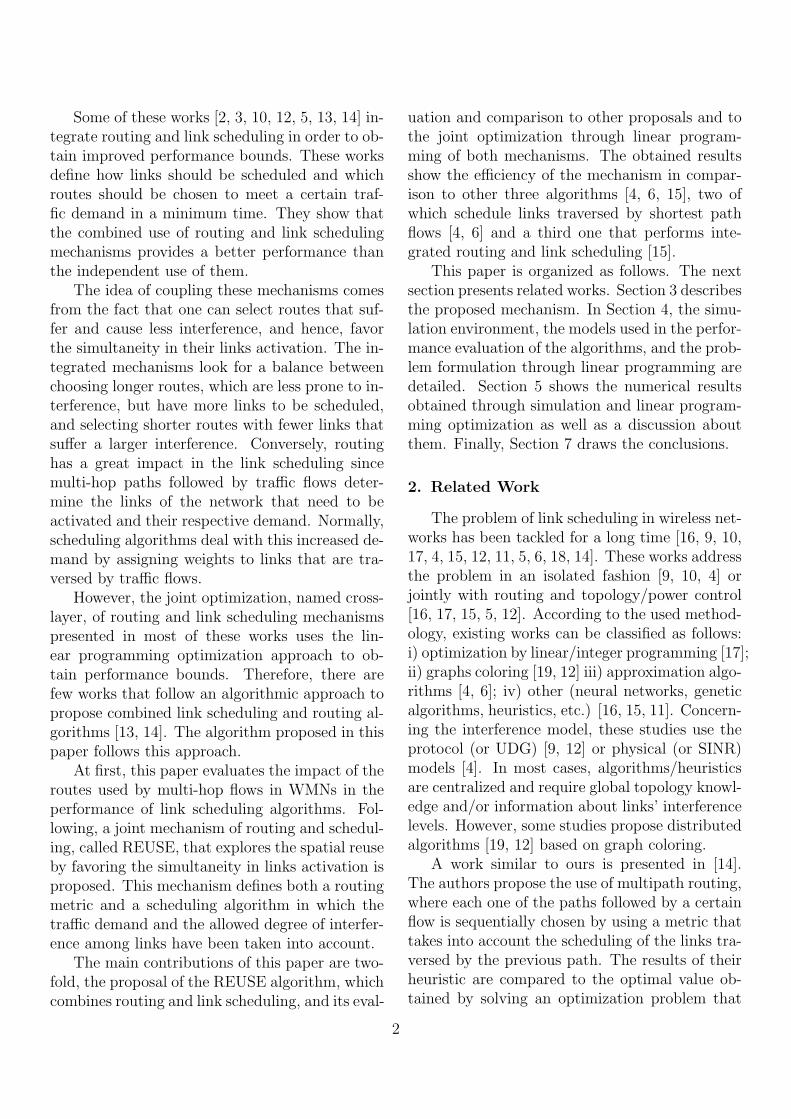
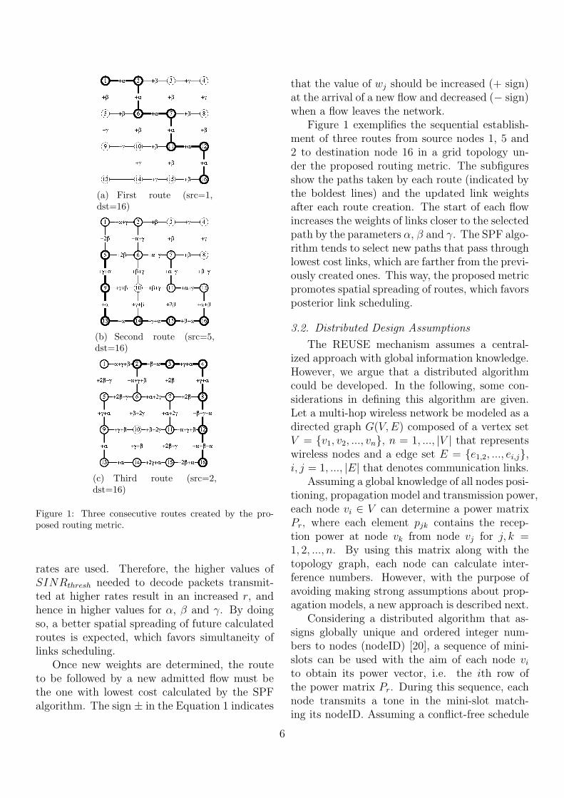
Figure 2: Number of route combinations as a function ofH.
mechanism is compared to three algorithms de-tailed in the subsections 2.1, 2.2 and 2.3. As thefirst two algorithms do not work together witha specific route selection algorithm, their perfor-mance is obtained for different sets of shortestpath routes.
Thus, it was implemented in the simulator avariant of the SPF algorithm that takes as inputa H parameter which has the following meaning.When H = −1, the algorithm returns the firstshortest path from source to destination found.When H = 0, it returns all shortest paths, andwhen H > 0, all paths with up to H hops higherthan the shortest path are found. The imple-mented algorithms are compared to the proposedmechanism for different values of H. When H =−1, only one route for each source will be used bythe algorithm, however, when H ≥ 0, the combi-nation of all routes for each source will be used inthe evaluation.
Considering a wireless network that has onlyone gateway node and where all links have trans-mission capacity of Wbits/s, the scheduling sizeT is related to the network capacity through C =W/T . Thus, the average size of the scheduling innumber of slots for that combination of routes willbe used as the performance metric to be evalu-ated. The smaller is the scheduling size the higheris the capacity.
The brute force method to the minimal sched-uling problem would be to use all routes, fromthe shortest up to N − 1 hops. However, the
number of route combinations presents a large in-crease with H, as shown in Figure 2. This figureshows the total number of computed routes whenH varies from 1 to 5 in scenarios of square gridnetworks. The destination node is the one placedat top-right corner of the grid topology and thesource nodes are the ones placed at the three othercorners. When H = 1 there are more than 100route combinations in a small 3x3 network, andmore than 10 million route combinations in a 7x7network. This result proves the infeasibility of abrute force computation.
4.1. Problem Formulation through Linear Program-ming
The LP formulation presented here is similarto the one described in [3]. It considers multi-ple flows, where each flow follows a single path,with a physical-based interference model. How-ever, additional constraints were added with thepurpose of obtaining the scheduling size as theperformance bound. Also, in our LP formulation,all flows receive equal throughputs provide thatthey have the same traffic demand.
The complete LP formulation, similar to theone presented in [3], is summarized below for thesake of clarity. Given a wireless network with Nnodes, the connectivity graph C(NC , LC) is com-posed by the vertex set NC (wireless nodes) andthe edge set LC (wireless links). There is a di-rected link lij from node ni to nj if SNRij >=SNRthresh and i = j, where SNRij means thesignal-to-noise ratio at the node nj for transmis-sions received from node ni, without consideringany interference.
Let us consider communication between mul-tiple sources, ns ∈ S, and a single destination, nd.Finding the maximum achievable throughput be-tween the sources and the destination using singlepath can be formulated as a linear program cor-responding to a multi-commodity flow problem.Also, let us consider that there are k commoditiesin M = {M1,M2, ...,Mk}, defined by Mi = (i, s),where ns is the source of commodity i. Thus, fijkdenotes the amount of flow on link lij from com-modity k, Capij denote the capacity of link lij,
8
and LC is a set of all links in the connectivitygraph.
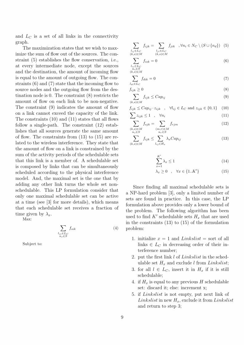
The maximization states that we wish to max-imize the sum of flow out of the sources. The con-straint (5) establishes the flow conservation, i.e.,at every intermediate node, except the sourcesand the destination, the amount of incoming flowis equal to the amount of outgoing flow. The con-straints (6) and (7) state that the incoming flow tosource nodes and the outgoing flow from the des-tination node is 0. The constraint (8) restricts theamount of flow on each link to be non-negative.The constraint (9) indicates the amount of flowon a link cannot exceed the capacity of the link.The constraints (10) and (11) states that all flowsfollow a single-path. The constraint (12) estab-lishes that all sources generate the same amountof flow. The constraints from (13) to (15) are re-lated to the wireless interference. They state thatthe amount of flow on a link is constrained by thesum of the activity periods of the schedulable setsthat this link is a member of. A schedulable setis composed by links that can be simultaneouslyscheduled according to the physical interferencemodel. And, the maximal set is the one that byadding any other link turns the whole set non-schedulable. This LP formulation consider thatonly one maximal schedulable set can be activeat a time (see [3] for more details), which meansthat each schedulable set receives a fraction oftime given by λx.
Max: ∑lsi∈LCns∈S
fsik (4)
Subject to:
∑lij∈LC
(k,s)∈M
fijk =∑
lji∈LC
(k,s)∈M
fjik , ∀ni ∈ NC \ (S ∪ {nd}) (5)
∑lis∈LCns∈S
(k,s)∈M
fisk = 0 (6)
∑ldi∈LC
fdik = 0 (7)
fijk ≥ 0 (8)∑(k,s)∈M
fijk ≤ Capij (9)
fijk ≤ Capij · zijk , ∀lij ∈ LC and zijk ∈ {0, 1} (10)∑zijk ≤ 1 , ∀ni (11)∑
(k,s)∈Mns∈S
fsjk =∑
(m,r)∈Mnr∈S
frjm (12)
∑(k,s)∈M
fijk ≤∑
lij∈Hx
λxCapij (13)
K′∑x=1
λx ≤ 1 (14)
λx ≥ 0 , ∀x ∈ {1..K ′} (15)
Since finding all maximal schedulable sets isa NP-hard problem [3], only a limited number ofsets are found in practice. In this case, the LPformulation above provides only a lower bound ofthe problem. The following algorithm has beenused to find K ′ schedulable sets Hx that are usedin the constraints (13) to (15) of the formulationproblem:
1. initialize x = 1 and Linkslist = sort of alllinks ∈ LC in decreasing order of their in-terference number;
2. put the first link l of Linkslist in the sched-ulable set Hx and exclude l from Linkslist;
3. for all l ∈ LC , insert it in Hx if it is stillschedulable;
4. if Hx is equal to any previous H schedulableset: discard it; else: increment x;
5. if Linkslist is not empty, put next link ofLinkslist in newHx, exclude it from Linkslistand return to step 3;
9
6. if schedulable sets converge: exit; else: cre-ate a new randomized Linkslist of all links∈ LC , and return to step 2.
The algorithm above can find all maximal sched-ulable sets if it is fed with all links list permuta-tion (m! inputs, wherem is the number of networklinks) instead of randomized lists, as cited in thestep 6. We use a convergence criteria to limit thecomputational cost. If steps from 2 to 5 do notincrement the number of schedulable sets for 10times, we stop the algorithm. Other stop criteriais to use 50 thousands link randomization, or xgreater then 200 thousands since a large numberof schedulable sets increases computational costof linear programming solution.
5. Numeric Results
We have developed our own simulator using Clanguage, which implements the SPF algorithmfor routing and all link scheduling mechanismsevaluated. Also, it implements the log-distancepropagation and physical interference models.
We have performed simulations using two dis-tinct topologies: grid and pseudo-random. Inboth scenarios, the data traffic flows in multiplehops from the sources to the gateway, which isalways placed in one of the corners of the squarearea covered by the network. Traffic sources arechosen amongst the nodes placed at the bordersdiametrically opposed to the gateway, which arethe farthest nodes from the gateway. Traffic de-mands are equal among all source nodes.
At the grid topology, nodes are horizontallyand vertically distant from each other by 70% ofthe maximum communication range. This place-ment allows direct communication with neighborsplaced in the diagonal. The maximum commu-nication range is calculated taking into accountthe transmission power (Pt), the path-loss expo-nent (α) and the minimum signal-to-noise ratio(SINRthresh).
The pseudo-random topologies are created byusing the following rules. The position of a newnode is randomly chosen following a uniform dis-tribution. This new node is inserted in the topol-ogy only when it is within the communication
range of at least one previously placed node, andthe degree of the network graph does not exceeda maximum threshold. Moreover, we also guar-antee a minimum distance between all pairs ofnodes. The parametrization chosen for this eval-uation were the following: Pt is set to 17 dBm; αranges between 5 and 30 dB; the maximum degreeranges between 6 and 9; and the minimum dis-tance between nodes is equal to 25% of the max-imum communication range. We have also per-formed simulations with varying number of sourcenodes.
As previously mentioned, the performance met-ric used to evaluate the mechanisms is the size ofTDMA cycle in number of slots, hereafter referredto as the scheduling size. As stated in Section 4,this performance metric is inversely related to thenetwork capacity. The four evaluated mechanismsand their respective acronyms are: GreedyPhy[4] (GPHY), the algorithms presented in [6] (LDF- Lesser Distance First) and in [15] (IRMA - In-tegrated Routing and MAC Scheduling), and ourproposal REUSE. Moreover, we also plot the opti-mal results obtained by the solution of the Lin-ear Program described in Section 4.1 (LP). Weused the open-source GLPK package [21] to solvethe LP formulation. However, some results of theLP were omitted because of the limitation of thealgorithm used to find the maximal schedulablesets. The algorithm is surely unable to find allmaximal schedulable sets whenever its executionis stopped because 50 thousand link randomiza-tion were reached or 200 thousand schedulablesets were found. At those cases, the lower boundsprovided by the LP formulation were assumed tobe far from the optimal result and were omittedin the graphs.
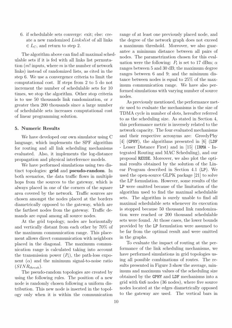
To evaluate the impact of routing at the per-formance of the link scheduling mechanisms, wehave performed simulations in grid topologies us-ing all possible combinations of routes. The re-sults presented in Figure 3 show the average, min-imum and maximum values of the scheduling sizeobtained by the GPHY and LDF mechanisms into agrid with 6x6 nodes (36 nodes), where five sourcenodes located at the edges diametrically opposedto the gateway are used. The vertical bars in
10
5
10
15
20
25
30
35
3 4 5
sche
dulin
g si
ze
α
GPHYLDFREUSEIRMA
(a) SINRthresh = 5dB
0
5
10
15
20
25
5 10 15 20 25 30
sche
dulin
g si
ze
SINRthresh (dB)
GPHYLDFREUSEIRMALP
(b) α = 5
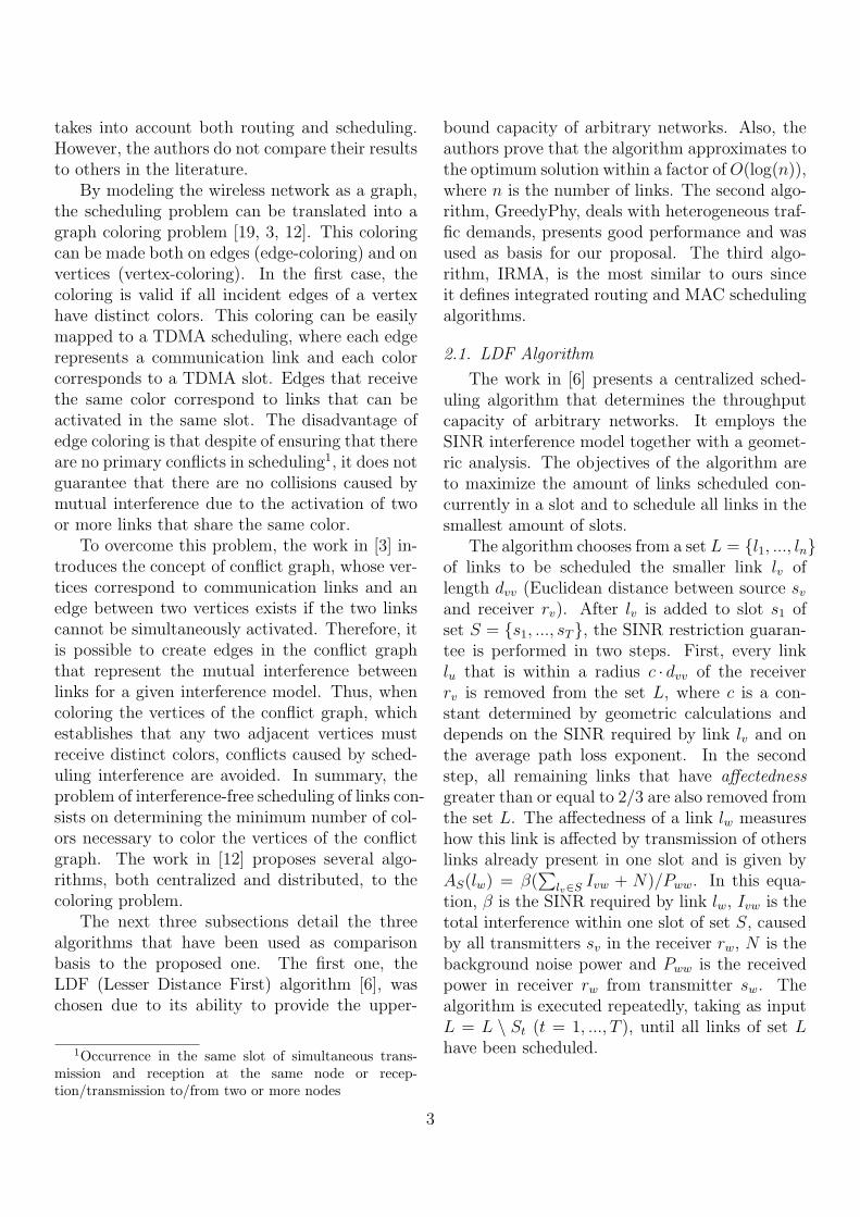
Figure 3: Average, min. and max. scheduling size (6x6grid and H = 0).
the graph are plotted between the minimum andmaximum values while the curve indicates theaverage scheduling size for the whole combina-tion of routes. These results are compared tothe ones obtained by the REUSE and IRMA mech-anisms, which choose specific routes according totheir specialized link weight metrics. Moreover,the optimal results provided by the LP formu-lation are included for benchmarking purposes.For the GPHY and LDF simulations, all routes withnumber of hops equal to the shortest path route(SPF with H = 0) are obtained and combinedleading to 176400 route combinations. The num-ber of possible combinations grows with the num-ber of source nodes and routes of the same sizefrom these sources to the gateway. In a grid topol-ogy, there are an increasing number of routes ofsame cost as function of the distance between thesource and the gateway. For example, by us-ing H = 1 for this same topology and the samenumber of sources, the number of combination ofroutes is superior to 6× 10⁹.
Figure 3 shows that LDF and GPHY exhibit avarying performance according to the route com-bination used since minimum and maximum val-ues for the scheduling size present a wide diver-gence. This shows the impact of routes choice onthe link scheduling performance. Moreover, onecan notice that the REUSE mechanism presentssmaller average scheduling sizes than the othersolutions, giving results close to the minimum ob-
5
10
15
20
25
3 4 5
sche
dulin
g si
ze
α
GPHYLDFREUSEIRMALP
(a) SINRthresh = 5dB
0
5
10
15
5 10 15 20 25 30
sche
dulin
g si
ze
SINRthresh (dB)
GPHYLDFREUSEIRMALP
(b) α = 5
Figure 4: Average, min. and max. scheduling size (4x5grid and H = 1).
tained by the GPHY algorithm. This indicates thatthe proposed mechanism is able to find routesthat allow better link scheduling. Otherwise, theIRMA mechanism provides poor results, with aver-age scheduling sizes close to LDF. It occurs mainlybecause differently from REUSE the link schedul-ing algorithm of IRMA incrementally schedules thelinks of each discovered route, without reschedul-ing the links of the previously discovered ones.Therefore, IRMA has difficulties to improve globalperformance, even by using a specialized link weightmetric.
Figure 4 shows the same results for a twentynode grid (4x5) with five source nodes by combin-ing all routes up to one hop larger than the short-est path route (H = 1). In this case, there aremore than three millions of combinations. Theaverage scheduling size for GPHY and LDF algo-rithms were obtained for all route combinations,and are compared to the result of the proposedmechanism. Here again, the REUSE provides bet-ter results, lower than the average and close to theminimum values obtained with GPHY, and IRMA isunable to achieve the same performance of REUSEin most scenarios.
Also in Figures 3 and 4, one can see that theperformance of the REUSE mechanism is still awayfrom the optimal results obtained by the LP for-mulation in many scenarios. It is also interestingto notice that in the 4x5 grid, some minimum val-ues of the scheduling size obtained by the GPHY
11
0
50
100
150
200
20 40 60 80 100
sche
dulin
g si
ze
number of nodes
GPHYLDFREUSEIRMALP
(a) SINRthresh = 5dB
0
50
100
150
200
20 40 60 80 100
sche
dulin
g si
ze
number of nodes
GPHYLDFREUSEIRMALP
(b) SINRthresh = 10dB
0
50
100
150
200
20 40 60 80 100
sche
dulin
g si
ze
number of nodes
GPHYLDFREUSEIRMALP
(c) SINRthresh = 15dB
0
50
100
150
200
20 40 60 80 100
sche
dulin
g si
ze
number of nodes
GPHYLDFREUSEIRMALP
(d) SINRthresh = 20dB
0
50
100
150
200
20 40 60 80 100
sche
dulin
g si
ze
number of nodes
GPHYLDFREUSEIRMALP
(e) SINRthresh = 25dB
0
50
100
150
200
20 40 60 80 100
sche
dulin
g si
ze
number of nodes
GPHYLDFREUSEIRMALP
(f) SINRthresh = 30dB
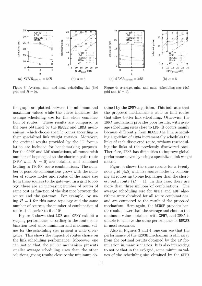
Figure 5: Scheduling size as a function of the number ofnodes for α = 3.
algorithm are equal to the optimum. It provesthe importance of the careful selection of routes,which is able to provide optimal performance tothe network.
In what follows, we present the results ob-tained by increasing the number of nodes in gridtopologies. We used NxN grids, where N nodesare placed in each line and column. In these ex-periments, all nodes located at the borders dia-
0
50
100
150
200
20 40 60 80 100
sche
dulin
g si
ze
number of nodes
GPHYLDFREUSEIRMALP
(a) SINRthresh = 5dB
0
50
100
150
200
20 40 60 80 100
sche
dulin
g si
ze
number of nodes
GPHYLDFREUSEIRMALP
(b) SINRthresh = 10dB
0
50
100
150
200
20 40 60 80 100
sche
dulin
g si
ze
number of nodes
GPHYLDFREUSEIRMALP
(c) SINRthresh = 15dB
0
50
100
150
200
20 40 60 80 100
sche
dulin
g si
ze
number of nodes
GPHYLDFREUSEIRMALP
(d) SINRthresh = 20dB
0
50
100
150
200
20 40 60 80 100
sche
dulin
g si
ze
number of nodes
GPHYLDFREUSEIRMALP
(e) SINRthresh = 25dB
0
50
100
150
200
20 40 60 80 100
sche
dulin
g si
ze
number of nodes
GPHYLDFREUSEIRMALP
(f) SINRthresh = 30dB
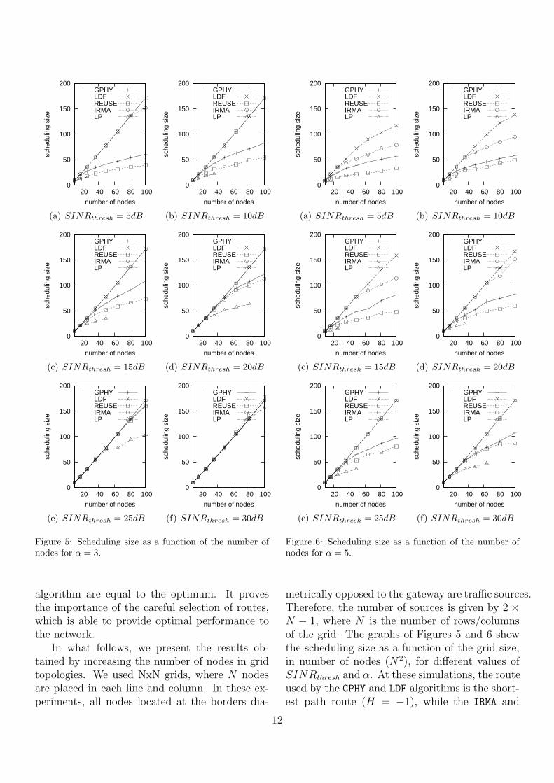
Figure 6: Scheduling size as a function of the number ofnodes for α = 5.
metrically opposed to the gateway are traffic sources.Therefore, the number of sources is given by 2 ×N − 1, where N is the number of rows/columnsof the grid. The graphs of Figures 5 and 6 showthe scheduling size as a function of the grid size,in number of nodes (N2), for different values ofSINRthresh and α. At these simulations, the routeused by the GPHY and LDF algorithms is the short-est path route (H = −1), while the IRMA and
12
30
50
70
90
110
130
150
3 3.5 4 4.5 5
aver
age
sche
dulin
g si
ze
α
GPHYLDFREUSEIRMA
(a) SINRthresh = 10dB,max. degree 6
30
50
70
90
110
130
150
3 3.5 4 4.5 5
aver
age
sche
dulin
g si
ze
α
GPHYLDFREUSEIRMA
(b) SINRthresh = 10dB,max. degree 9
30
50
70
90
110
130
150
3 3.5 4 4.5 5
aver
age
sche
dulin
g si
ze
α
GPHYLDFREUSEIRMA
(c) SINRthresh = 5dB,max. degree 9
30
50
70
90
110
130
150
3 3.5 4 4.5 5
aver
age
sche
dulin
g si
ze
α
GPHYLDFREUSEIRMA
(d) SINRthresh = 15dB,max. degree 9
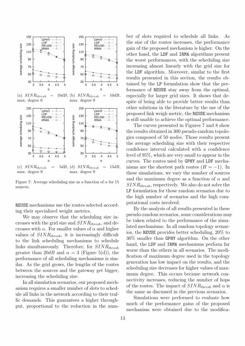
Figure 7: Average scheduling size as a function of α for 15sources.
REUSE mechanisms use the routes selected accord-ing their specialized weight metrics.
We may observe that the scheduling size in-creases with the grid size and SINRthresh, and de-creases with α. For smaller values of α and highervalues of SINRthresh, it is increasingly difficultto the link scheduling mechanisms to schedulelinks simultaneously. Therefore, for SINRthresh
greater than 20dB and α = 3 (Figure 5(d)), theperformance of all scheduling mechanisms is sim-ilar. As the grid grows, the lengths of the routesbetween the sources and the gateway get bigger,increasing the scheduling size.
In all simulation scenarios, our proposed mech-anism requires a smaller number of slots to sched-ule all links in the network according to their traf-fic demands. This guarantees a higher through-put, proportional to the reduction in the num-
ber of slots required to schedule all links. Asthe size of the routes increases, the performancegain of the proposed mechanism is higher. On theother hand, the LDF and IRMA algorithms presentthe worst performances, with the scheduling sizeincreasing almost linearly with the grid size forthe LDF algorithm. Moreover, similar to the firstresults presented in this section, the results ob-tained by the LP formulation show that the per-formance of REUSE stay away from the optimal,especially for larger grid sizes. It shows that de-spite of being able to provide better results thanother solutions in the literature by the use of theproposed link weigh metric, the REUSE mechanismis still unable to achieve the optimal performance.
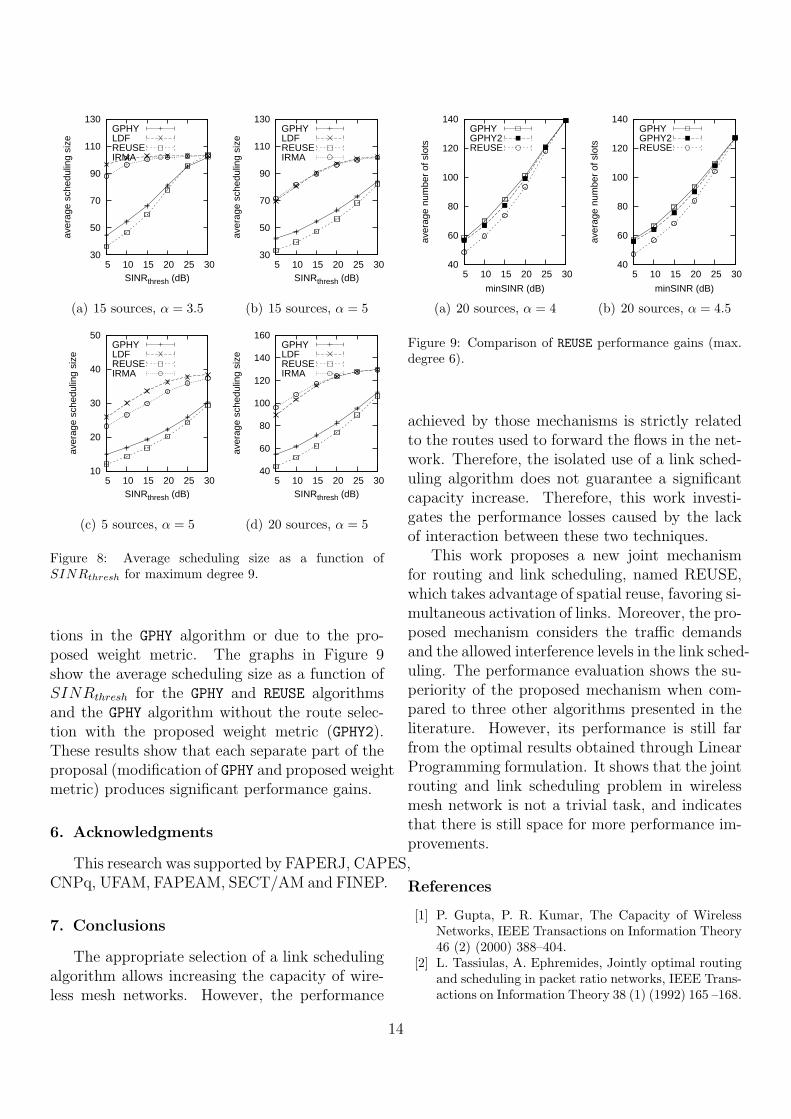
The curves presented in Figures 7 and 8 showthe results obtained in 300 pseudo-random topolo-gies composed of 50 nodes. Those results presentthe average scheduling size with their respectiveconfidence interval calculated with a confidencelevel of 95%, which are very small to appear in thecurves. The routes used by GPHY and LDF mecha-nisms are the shortest path routes (H = −1). Inthese simulations, we vary the number of sourcesand the maximum degree as a function of α andSINRthresh, respectively. We also do not solve theLP formulation for those random scenarios due tothe high number of scenarios and the high com-putational costs involved.
By the analysis of all results presented in thesepseudo-random scenarios, some considerations maybe taken related to the performance of the simu-lated mechanisms. In all random topology scenar-ios, the REUSE provides better scheduling, 20% to30% smaller than GPHY algorithm. On the otherhand, the LDF and IRMA mechanisms perform farworse than the others in all scenarios. The modi-fication of maximum degree used in the topologygeneration has low impact on the results, and thescheduling size decreases for higher values of max-imum degree. This occurs because network con-nectivity increases, reducing the number of hopsof the routes. The impact of SINRthresh and α isthe same as discussed in the previous scenarios.
Simulations were performed to evaluate howmuch of the performance gains of the proposedmechanism were obtained due to the modifica-
13
30
50
70
90
110
130
5 10 15 20 25 30
aver
age
sche
dulin
g si
ze
SINRthresh (dB)
GPHYLDFREUSEIRMA
(a) 15 sources, α = 3.5
30
50
70
90
110
130
5 10 15 20 25 30
aver
age
sche
dulin
g si
ze
SINRthresh (dB)
GPHYLDFREUSEIRMA
(b) 15 sources, α = 5
10
20
30
40
50
5 10 15 20 25 30
aver
age
sche
dulin
g si
ze
SINRthresh (dB)
GPHYLDFREUSEIRMA
(c) 5 sources, α = 5
40
60
80
100
120
140
160
5 10 15 20 25 30
aver
age
sche
dulin
g si
ze
SINRthresh (dB)
GPHYLDFREUSEIRMA
(d) 20 sources, α = 5
Figure 8: Average scheduling size as a function ofSINRthresh for maximum degree 9.
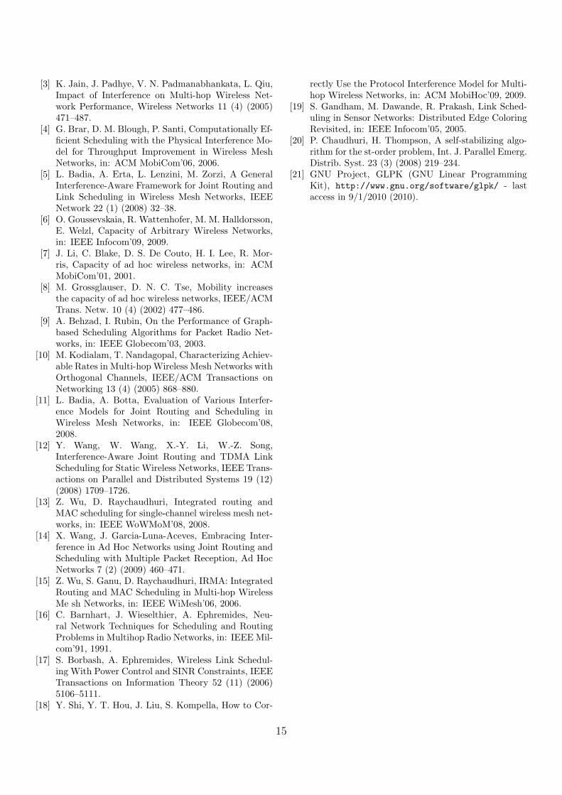
tions in the GPHY algorithm or due to the pro-posed weight metric. The graphs in Figure 9show the average scheduling size as a function ofSINRthresh for the GPHY and REUSE algorithmsand the GPHY algorithm without the route selec-tion with the proposed weight metric (GPHY2).These results show that each separate part of theproposal (modification of GPHY and proposed weightmetric) produces significant performance gains.
6. Acknowledgments
This research was supported by FAPERJ, CAPES,CNPq, UFAM, FAPEAM, SECT/AM and FINEP.
7. Conclusions
The appropriate selection of a link schedulingalgorithm allows increasing the capacity of wire-less mesh networks. However, the performance
40
60
80
100
120
140
5 10 15 20 25 30
aver
age
num
ber
of s
lots
minSINR (dB)
GPHYGPHY2REUSE
(a) 20 sources, α = 4
40
60
80
100
120
140
5 10 15 20 25 30
aver
age
num
ber
of s
lots
minSINR (dB)
GPHYGPHY2REUSE
(b) 20 sources, α = 4.5
Figure 9: Comparison of REUSE performance gains (max.degree 6).
achieved by those mechanisms is strictly relatedto the routes used to forward the flows in the net-work. Therefore, the isolated use of a link sched-uling algorithm does not guarantee a significantcapacity increase. Therefore, this work investi-gates the performance losses caused by the lackof interaction between these two techniques.
This work proposes a new joint mechanismfor routing and link scheduling, named REUSE,which takes advantage of spatial reuse, favoring si-multaneous activation of links. Moreover, the pro-posed mechanism considers the traffic demandsand the allowed interference levels in the link sched-uling. The performance evaluation shows the su-periority of the proposed mechanism when com-pared to three other algorithms presented in theliterature. However, its performance is still farfrom the optimal results obtained through LinearProgramming formulation. It shows that the jointrouting and link scheduling problem in wirelessmesh network is not a trivial task, and indicatesthat there is still space for more performance im-provements.
References
[1] P. Gupta, P. R. Kumar, The Capacity of WirelessNetworks, IEEE Transactions on Information Theory46 (2) (2000) 388–404.
[2] L. Tassiulas, A. Ephremides, Jointly optimal routingand scheduling in packet ratio networks, IEEE Trans-actions on Information Theory 38 (1) (1992) 165 –168.
14
[3] K. Jain, J. Padhye, V. N. Padmanabhankata, L. Qiu,Impact of Interference on Multi-hop Wireless Net-work Performance, Wireless Networks 11 (4) (2005)471–487.
[4] G. Brar, D. M. Blough, P. Santi, Computationally Ef-ficient Scheduling with the Physical Interference Mo-del for Throughput Improvement in Wireless MeshNetworks, in: ACM MobiCom’06, 2006.
[5] L. Badia, A. Erta, L. Lenzini, M. Zorzi, A GeneralInterference-Aware Framework for Joint Routing andLink Scheduling in Wireless Mesh Networks, IEEENetwork 22 (1) (2008) 32–38.
[6] O. Goussevskaia, R. Wattenhofer, M. M. Halldorsson,E. Welzl, Capacity of Arbitrary Wireless Networks,in: IEEE Infocom’09, 2009.
[7] J. Li, C. Blake, D. S. De Couto, H. I. Lee, R. Mor-ris, Capacity of ad hoc wireless networks, in: ACMMobiCom’01, 2001.
[8] M. Grossglauser, D. N. C. Tse, Mobility increasesthe capacity of ad hoc wireless networks, IEEE/ACMTrans. Netw. 10 (4) (2002) 477–486.
[9] A. Behzad, I. Rubin, On the Performance of Graph-based Scheduling Algorithms for Packet Radio Net-works, in: IEEE Globecom’03, 2003.
[10] M. Kodialam, T. Nandagopal, Characterizing Achiev-able Rates in Multi-hop Wireless Mesh Networks withOrthogonal Channels, IEEE/ACM Transactions onNetworking 13 (4) (2005) 868–880.
[11] L. Badia, A. Botta, Evaluation of Various Interfer-ence Models for Joint Routing and Scheduling inWireless Mesh Networks, in: IEEE Globecom’08,2008.
[12] Y. Wang, W. Wang, X.-Y. Li, W.-Z. Song,Interference-Aware Joint Routing and TDMA LinkScheduling for Static Wireless Networks, IEEE Trans-actions on Parallel and Distributed Systems 19 (12)(2008) 1709–1726.
[13] Z. Wu, D. Raychaudhuri, Integrated routing andMAC scheduling for single-channel wireless mesh net-works, in: IEEE WoWMoM’08, 2008.
[14] X. Wang, J. Garcia-Luna-Aceves, Embracing Inter-ference in Ad Hoc Networks using Joint Routing andScheduling with Multiple Packet Reception, Ad HocNetworks 7 (2) (2009) 460–471.
[15] Z. Wu, S. Ganu, D. Raychaudhuri, IRMA: IntegratedRouting and MAC Scheduling in Multi-hop WirelessMe sh Networks, in: IEEE WiMesh’06, 2006.
[16] C. Barnhart, J. Wieselthier, A. Ephremides, Neu-ral Network Techniques for Scheduling and RoutingProblems in Multihop Radio Networks, in: IEEE Mil-com’91, 1991.
[17] S. Borbash, A. Ephremides, Wireless Link Schedul-ing With Power Control and SINR Constraints, IEEETransactions on Information Theory 52 (11) (2006)5106–5111.
[18] Y. Shi, Y. T. Hou, J. Liu, S. Kompella, How to Cor-
rectly Use the Protocol Interference Model for Multi-hop Wireless Networks, in: ACM MobiHoc’09, 2009.
[19] S. Gandham, M. Dawande, R. Prakash, Link Sched-uling in Sensor Networks: Distributed Edge ColoringRevisited, in: IEEE Infocom’05, 2005.
[20] P. Chaudhuri, H. Thompson, A self-stabilizing algo-rithm for the st-order problem, Int. J. Parallel Emerg.Distrib. Syst. 23 (3) (2008) 219–234.
[21] GNU Project, GLPK (GNU Linear ProgrammingKit), http://www.gnu.org/software/glpk/ - lastaccess in 9/1/2010 (2010).
15
Related Documents


![Boosting Spatial Reuse via Multiple Paths Multi-Hop ...arXiv:1509.07329v1 [cs.NI] 24 Sep 2015 1 Boosting Spatial Reuse via Multiple Paths Multi-Hop Scheduling for Directional mmWave](https://static.cupdf.com/doc/110x72/5e86c185200cda12df530976/boosting-spatial-reuse-via-multiple-paths-multi-hop-arxiv150907329v1-csni.jpg)