1 E 7.108.6/11.16 Return line and Suction Boost Filter RKM up to 850 l/min, up to 10 bar 1. TECHNICAL SPECIFICATIONS 1.1 FILTER HOUSING Construction The filter housings are designed in accordance with international regulations. They consist of a filter head, filter bowl and a screw-on or bolt-on cover plate. Standard equipment: with bypass valve with back-pressure valve without anti-cavitation valve Application RKM return line & suction boost filters are ideally suited for use in equipment with two or more circuits. In particular this filter is the "first choice" for mobile machinery using hydrostatic drives (e.g. wheel loaders, fork-lift trucks, harvesting machines), if the return flow is greater than the flow required on the suction side under operating conditions. Function The return flow of the operating hydraulics is supplied to the filter via one or several inlets "A" and is cleaned by the filter element (full flow return line filtration). A pressure of 0.5 bar (standard) is applied inside the element by the back-pressure valve "V1". This ensures that the filtered return line flow is available to the hydrostatic feed pumps connected in "B" ports (full flow suction boost filtration). The risk of cavitation is significantly reduced. The excess flow is drained to the tank via port "T". A bypass valve "V2" (standard = 2.5 bar) is fitted to relieve excessive back- pressures in the element (important on cold starts when viscosity is high). This valve arrangement ensures that only finely filtered oil is available to the suction port during operation (exception: RKM 350). With optional valve "V3", oil can be drawn from the tank for short periods, e.g. initial filling, venting after changing element. 1.2 FILTER ELEMENTS The filter elements used in RKM filters are notable for low back-pressures, especially at high viscosities (e.g. cold starts). 1.9 COMPATIBILITY WITH HYDRAULIC FLUIDS ISO 2943 Hydraulic oils H to HLPD DIN 51524 Lubrication oils DIN 51517, API, ACEA, DIN 51515, ISO 6743 Compressor oils DIN 51506 Biodegradable operating fluids VDMA 24568 HETG, HEES, HEPG Fire-resistant fluids HFA, HFB, HFC und HFD Operating fluids with high water content (>50% water content) on request 1.10 IMPORTANT INFORMATION Filter housings must be earthed. When using electrical clogging indicators, the electrical power supply to the system must be switched off before removing the clogging indicator connector. 1.3 FILTER SPECIFICATIONS Nominal pressure 10 bar Temperature range -30 °C to +100 °C (short-term: -40 °C) Material of filter head Aluminium Material of filter bowl Steel (all RKM except RKM 300) Polyamide (RKM 300) Material of cover plate Polyamide (RKM 80 to 251, 350) Aluminium (RKM 300, 400, 800) Type of clogging indicator VMF – Connection thread G 1/8 Pressure setting of the clogging indicator -0.2 bar (vacuum pressure) 2 bar (back-pressure) (others on request) Bypass cracking pressure (V2) 2.5 bar (others on request) Setting for back-pressure valve (V1) 0.5 bar (others on request) Symbol for hydraulic systems RKM 80 RKM 100 RKM 120 RKM 151 RKM 201 RKM 251 RKM 201/-TH RKM 300 RKM 400 RKM 800 HYDAC filter elements are validated and their quality is constantly monitored according to the following standards: ISO 2941, ISO 2942, ISO 2943, ISO 3724, ISO 3968, ISO 11170 ISO 16889 Filter elements are available with the following pressure stability values: Mobilemicron ® (MM): 10 bar 1.4 SEALS Perbunan (=NBR) 1.5 MOUNTING Tank-top filter 1.6 SPECIAL MODELS AND ACCESSORIES with bleed valve with multiport head (only RKM 80 to 251; see point 2.4) with integral thermal bypass valve (only RKM 151, 201, 251; see point 2.5) with anti-cavitation valve (V3) 1.7 SPARE PARTS See Original Spare Parts List 1.8 CERTIFICATES AND APPROVALS On request RKM 350 VA = clogging indicator

Welcome message from author
This document is posted to help you gain knowledge. Please leave a comment to let me know what you think about it! Share it to your friends and learn new things together.
Transcript
1
E 7.
108.
6/11
.16
Return line and Suction Boost Filter RKMup to 850 l/min, up to 10 bar
1. TECHNICAL SPECIFICATIONS
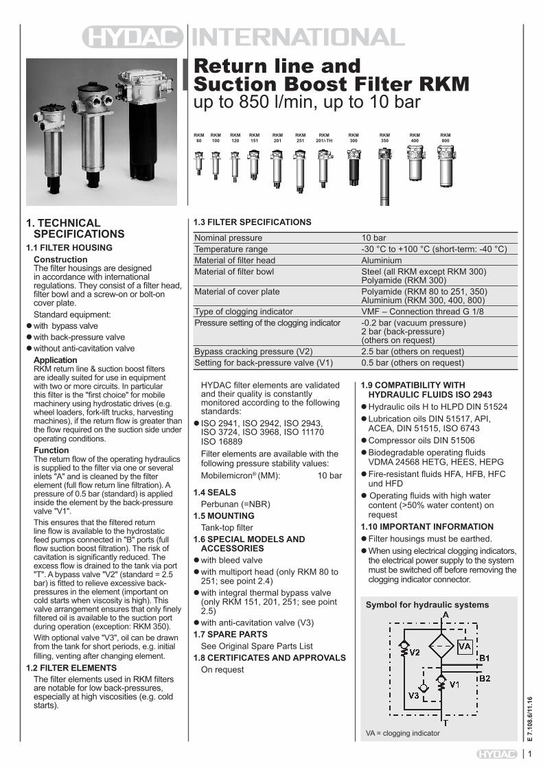
1.1 FILTER HOUSINGConstruction The filter housings are designed in accordance with international regulations. They consist of a filter head, filter bowl and a screw-on or bolt-on cover plate. Standard equipment:
with bypass valve with back-pressure valve without anti-cavitation valve
Application RKM return line & suction boost filters are ideally suited for use in equipment with two or more circuits. In particular this filter is the "first choice" for mobile machinery using hydrostatic drives (e.g. wheel loaders, fork-lift trucks, harvesting machines), if the return flow is greater than the flow required on the suction side under operating conditions.Function The return flow of the operating hydraulics is supplied to the filter via one or several inlets "A" and is cleaned by the filter element (full flow return line filtration). A pressure of 0.5 bar (standard) is applied inside the element by the back-pressure valve "V1".This ensures that the filtered return line flow is available to the hydrostatic feed pumps connected in "B" ports (full flow suction boost filtration). The risk of cavitation is significantly reduced. The excess flow is drained to the tank via port "T". A bypass valve "V2" (standard = 2.5 bar) is fitted to relieve excessive back-pressures in the element (important on cold starts when viscosity is high). This valve arrangement ensures that only finely filtered oil is available to the suction port during operation (exception: RKM 350).With optional valve "V3", oil can be drawn from the tank for short periods, e.g. initial filling, venting after changing element.
1.2 FILTER ELEMENTSThe filter elements used in RKM filters are notable for low back-pressures, especially at high viscosities (e.g. cold starts).
1.9 COMPATIBILITY WITH HYDRAULIC FLUIDS ISO 2943
Hydraulic oils H to HLPD DIN 51524 Lubrication oils DIN 51517, API,
ACEA, DIN 51515, ISO 6743 Compressor oils DIN 51506 Biodegradable operating fluids
VDMA 24568 HETG, HEES, HEPG Fire-resistant fluids HFA, HFB, HFC
und HFD Operating fluids with high water
content (>50% water content) on request
1.10 IMPORTANT INFORMATION Filter housings must be earthed. When using electrical clogging indicators,
the electrical power supply to the system must be switched off before removing the clogging indicator connector.
1.3 FILTER SPECIFICATIONS
Nominal pressure 10 bar Temperature range -30 °C to +100 °C (short-term: -40 °C) Material of filter head Aluminium Material of filter bowl Steel (all RKM except RKM 300) Polyamide (RKM 300) Material of cover plate Polyamide (RKM 80 to 251, 350) Aluminium (RKM 300, 400, 800) Type of clogging indicator VMF – Connection thread G 1/8 Pressure setting of the clogging indicator -0.2 bar (vacuum pressure) 2 bar (back-pressure) (others on request) Bypass cracking pressure (V2) 2.5 bar (others on request) Setting for back-pressure valve (V1) 0.5 bar (others on request)
Symbol for hydraulic systems
RKM 80
RKM 100
RKM 120
RKM 151
RKM 201
RKM 251
RKM 201/-TH
RKM 300
RKM 400
RKM 800
HYDAC filter elements are validated and their quality is constantly monitored according to the following standards:
ISO 2941, ISO 2942, ISO 2943, ISO 3724, ISO 3968, ISO 11170 ISO 16889Filter elements are available with the following pressure stability values:Mobilemicron® (MM): 10 bar
1.4 SEALSPerbunan (=NBR)
1.5 MOUNTINGTank-top filter
1.6 SPECIAL MODELS AND ACCESSORIES
with bleed valve with multiport head (only RKM 80 to
251; see point 2.4) with integral thermal bypass valve
(only RKM 151, 201, 251; see point 2.5)
with anti-cavitation valve (V3)1.7 SPARE PARTS
See Original Spare Parts List1.8 CERTIFICATES AND APPROVALS
On request
RKM 350
VA = clogging indicator
E 7.
108.
6/11
.16
2
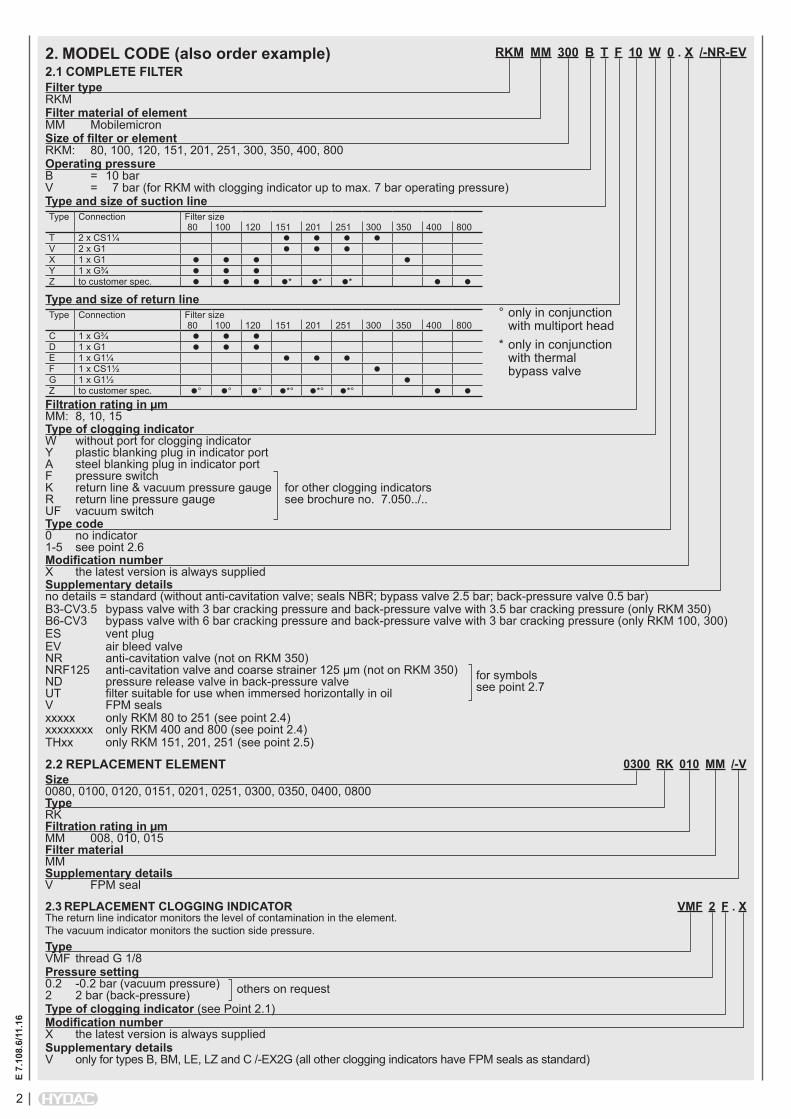
RKM MM 300 B T F 10 W 0 . X /-NR-EV
Filter type RKMFilter material of element MM MobilemicronSize of filter or element RKM: 80, 100, 120, 151, 201, 251, 300, 350, 400, 800Operating pressure B = 10 bar V = 7 bar (for RKM with clogging indicator up to max. 7 bar operating pressure)Type and size of suction lineType Connection Filter size
80 100 120 151 201 251 300 350 400 800T 2 x CS1¼ V 2 x G1 X 1 x G1 Y 1 x G¾ Z to customer spec. * * *
Type and size of return lineType Connection Filter size
80 100 120 151 201 251 300 350 400 800C 1 x G¾ D 1 x G1 E 1 x G1¼ F 1 x CS1½ G 1 x G1½ Z to customer spec. ° ° ° *° *° *°
Filtration rating in µm MM: 8, 10, 15Type of clogging indicator W without port for clogging indicator Y plastic blanking plug in indicator port A steel blanking plug in indicator port F pressure switch K return line & vacuum pressure gauge for other clogging indicators R return line pressure gauge see brochure no. 7.050../.. UF vacuum switchType code 0 no indicator 1-5 see point 2.6Modification number X the latest version is always suppliedSupplementary details no details = standard (without anti-cavitation valve; seals NBR; bypass valve 2.5 bar; back-pressure valve 0.5 bar)B3-CV3.5 bypass valve with 3 bar cracking pressure and back-pressure valve with 3.5 bar cracking pressure (only RKM 350) B6-CV3 bypass valve with 6 bar cracking pressure and back-pressure valve with 3 bar cracking pressure (only RKM 100, 300)ES vent plugEV air bleed valve NR anti-cavitation valve (not on RKM 350) NRF125 anti-cavitation valve and coarse strainer 125 µm (not on RKM 350) for symbols ND pressure release valve in back-pressure valve see point 2.7 UT filter suitable for use when immersed horizontally in oil V FPM sealsxxxxx only RKM 80 to 251 (see point 2.4) xxxxxxxx only RKM 400 and 800 (see point 2.4)THxx only RKM 151, 201, 251 (see point 2.5)
2. MODEL CODE (also order example)2.1 COMPLETE FILTER
0300 RK 010 MM /-VSize 0080, 0100, 0120, 0151, 0201, 0251, 0300, 0350, 0400, 0800Type RKFiltration rating in µm MM 008, 010, 015Filter material MMSupplementary details V FPM seal
2.2 REPLACEMENT ELEMENT
2.3 REPLACEMENT CLOGGING INDICATOR VMF 2 F . XThe return line indicator monitors the level of contamination in the element. The vacuum indicator monitors the suction side pressure.Type VMF thread G 1/8Pressure setting 0.2 -0.2 bar (vacuum pressure) others on request 2 2 bar (back-pressure)Type of clogging indicator (see Point 2.1)Modification number X the latest version is always suppliedSupplementary details V only for types B, BM, LE, LZ and C /-EX2G (all other clogging indicators have FPM seals as standard)
* only in conjunction with thermal bypass valve
° only in conjunction with multiport head
3
E 7.
108.
6/11
.16
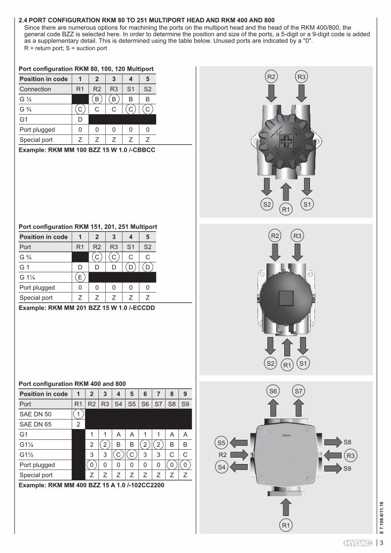
2.4 PORT CONFIGURATION RKM 80 TO 251 MULTIPORT HEAD AND RKM 400 AND 800Since there are numerous options for machining the ports on the multiport head and the head of the RKM 400/800, the general code BZZ is selected here. In order to determine the position and size of the ports, a 5-digit or a 9-digit code is added as a supplementary detail. This is determined using the table below. Unused ports are indicated by a "0".R = return port; S = suction port
S2
Port configuration RKM 80, 100, 120 MultiportPosition in code 1 2 3 4 5Connection R1 R2 R3 S1 S2G ½ B B B BG ¾ C C C C CG1 DPort plugged 0 0 0 0 0Special port Z Z Z Z ZExample: RKM MM 100 BZZ 15 W 1.0 /-CBBCC
Port configuration RKM 151, 201, 251 MultiportPosition in code 1 2 3 4 5Port R1 R2 R3 S1 S2G ¾ C C C CG 1 D D D D DG 1¼ EPort plugged 0 0 0 0 0Special port Z Z Z Z ZExample: RKM MM 201 BZZ 15 W 1.0 /-ECCDD
Port configuration RKM 400 and 800Position in code 1 2 3 4 5 6 7 8 9Port R1 R2 R3 S4 S5 S6 S7 S8 S9SAE DN 50 1SAE DN 65 2G1 1 1 A A 1 1 A AG1¼ 2 2 B B 2 2 B BG1½ 3 3 C C 3 3 C CPort plugged 0 0 0 0 0 0 0 0Special port Z Z Z Z Z Z Z ZExample: RKM MM 400 BZZ 15 A 1.0 /-102CC2200
R1S1
R2 R3
S2 R1 S1
R2 R3
S6 S7
R1
S5
S4
R3R2
S8
S9
E 7.
108.
6/11
.16
4
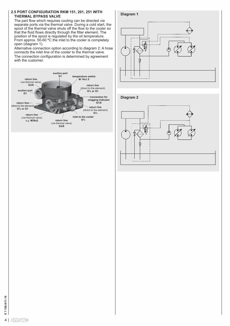
2.5 PORT CONFIGURATION RKM 151, 201, 251 WITH THERMAL BYPASS VALVEThe part flow which requires cooling can be directed via separate ports via the thermal valve. During a cold start, the spool of the thermal valve shuts off the flow to the cooler so that the fluid flows directly through the filter element. The position of the spool is regulated by the oil temperature. From approx. 50-60 ºC the inlet to the cooler is completely open (diagram 1). Alternative connection option according to diagram 2: A hose connects the inlet line of the cooler to the thermal valve.The connection configuration is determined by agreement with the customer.
Diagram 1
Diagram 2
suction port G1 temperature switch
M 14x1.5
return line (direct to the element)
G¾ or G1
connection for clogging indicator
G1/8
inlet to the cooler G¾
return line (direct to the element)
G¾
return line (via thermal valve)
G3/8
return line (via thermal valve)
e.g. M36x2
return line (direct to the element)
G¾ or G1
return line (via thermal valve)
G3/8
suction port G1

5
E 7.
108.
6/11
.16
2.6 TYPE CODERKM 80, 100, 120
RKM 151, 201, 251
RKM 300
Type Type of Measuring code clogging indicator 1.X Return line Before filter element2.X Return line Before filter element3.X Vacuum After filter element4.X Vacuum After filter element5.X 2 indicators: Before & after element Return line & vacuum
Type Type of Measuring code clogging indicator 1.X Return line Before filter element2.X Return line Before filter element3.X Vacuum After filter element5.X 2 indicators: Before & after element Return line & vacuum
Type Type of Measuring code clogging indicator1.X Return line Before filter element2.X Return line Before filter element3.X Vacuum After filter element4.X Vacuum After filter element5.X 2 indicators: Before & after element Return line & vacuum
RKM 400, 800 Type Type of Measuring code clogging indicator1.X Return line Before filter element2.X Return line Before filter element3.X Vacuum After filter element4.X Vacuum After filter element5.X 2 indicators: Before & after element Return line & vacuum
2.7 SYMBOLS/-ND/-NR /-NRF125 RKM 350
Other indicator configurations on request!
A
B
V2
V1
3 bar (2.5 bar)
3.5 bar (0.5 bar)

E 7.
108.
6/11
.16
6
3. FILTER CALCULATION / SIZINGThe total pressure drop of a filter at a certain flow rate Q is the sum of the housing ∆p and the element ∆p and is calculated as follows:∆ptotal = ∆phousing + ∆pelement
∆phousing = (see Point 3.1)
∆pelement = Q • SK* • viscosity 1000 30 (*see point 3.2)For ease of calculation, our Filter Sizing Program is available on request free of charge.NEW: Sizing online at www.hydac.com
3.1 GRADIENT COEFFICIENTS (SK) FOR FILTER ELEMENTSThe gradient coefficients in mbar/(l/min) apply to mineral oils with a kinematic viscosity of 30 mm²/s. The pressure drop changes proportionally to the change in viscosity.
RKM MM8 µm 10 µm 15 µm
80 2.70 2.70 1.60100 1.80 1.80 1.10120 1.40 1.40 0.90151 1.00 1.00 0.65201 0.75 0.75 0.47251 0.58 0.58 0.36300 0.62 0.62 0.39350 0.30 0.30 0.20400 0.56 0.56 0.35800 0.44 0.44 0.27
3.2 ∆p-Q HOUSING CURVES INCLUDING ELEMENT BASED ON ISO 3968The housing curves apply to mineral oil with a density of 0.86 kg/dm³ and a kinematic viscosity of 30 mm²/s. In this case, the differential pressure changes proportionally to the density.
∆p [b
ar]
Q [l/min]
RKM 80
∆p [b
ar]
Q [l/min]
RKM 100
∆p [b
ar]
Q [l/min]
RKM 251
∆p [b
ar]
Q [l/min]
RKM 300
∆p [b
ar]
Q [l/min]
RKM 120
∆p [b
ar]
Q [l/min]
RKM 151
∆p [b
ar]
Q [l/min]
RKM 400
∆p [b
ar]
Q [l/min]
RKM 800
∆p [b
ar]
Q [l/min]
RKM 201
∆p [b
ar]
Q [l/min]
RKM 350
7
E 7.
108.
6/11
.16
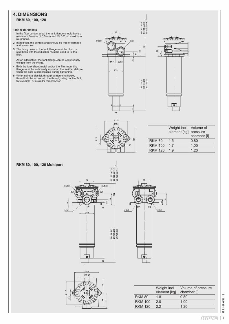
4. DIMENSIONSRKM 80, 100, 120
outlet
RKM 80, 100, 120 Multiport
Weight incl. element [kg]
Volume of pressure chamber [l]
RKM 80 1.5 0.80RKM 100 1.7 1.00RKM 120 1.9 1.20
Weight incl. element [kg]
Volume of pressure chamber [l]
RKM 80 1.8 0.80RKM 100 2.0 1.00RKM 120 2.2 1.20
inlet
outlet
inlet inlet inlet
outlet
Tank requirements1. In the filter contact area, the tank flange should have a
maximum flatness of 0.3 mm and Ra 3.2 µm maximum roughness.
2. In addition, the contact area should be free of damage and scratches.
3. The fixing holes of the tank flange must be blind, or stud bolts with threadlocker must be used to fix the filter. As an alternative, the tank flange can be continuously welded from the inside.
4. Both the tank sheet metal and/or the filter mounting flange must be sufficiently robust so that neither deform when the seal is compressed during tightening.
5. When using a dipstick through a mounting screw, threadlock the screw into the thread, using Loctite 243, for example, or a similar threadlocker..
E 7.
108.
6/11
.16
8
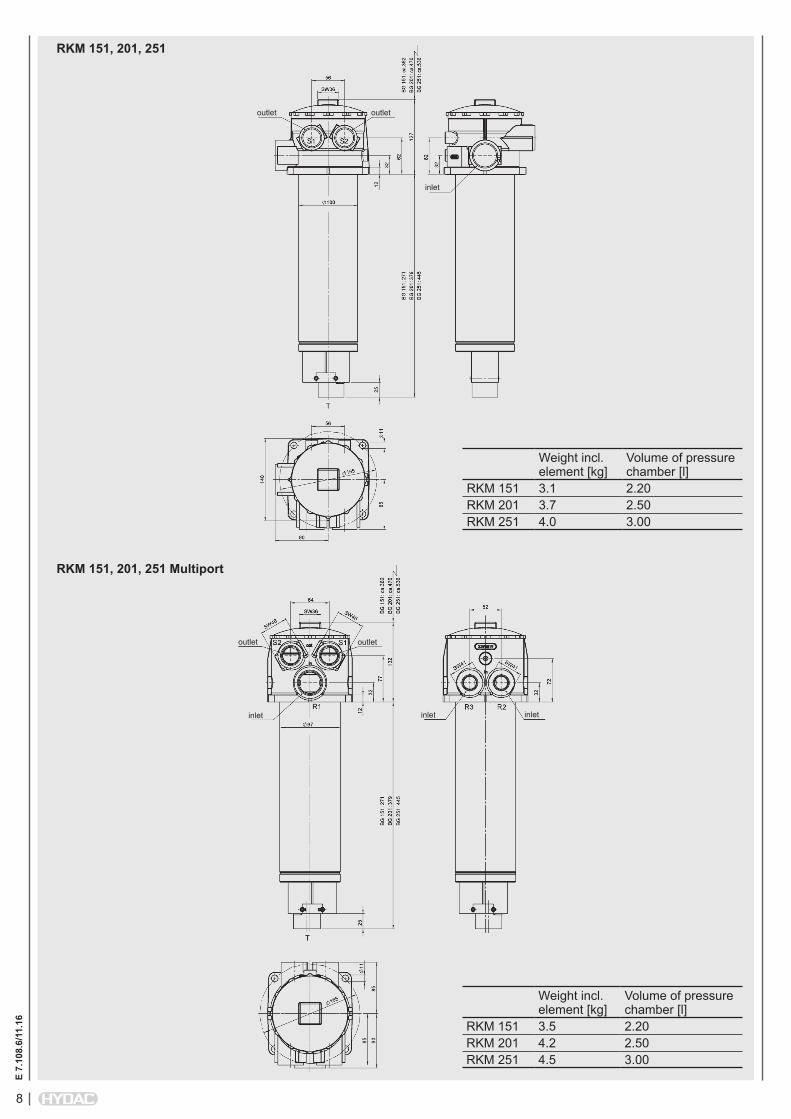
RKM 151, 201, 251
RKM 151, 201, 251 Multiport
Weight incl. element [kg]
Volume of pressure chamber [l]
RKM 151 3.1 2.20RKM 201 3.7 2.50RKM 251 4.0 3.00
Weight incl. element [kg]
Volume of pressure chamber [l]
RKM 151 3.5 2.20RKM 201 4.2 2.50RKM 251 4.5 3.00
outlet
inlet inlet inlet
outlet
inlet
outletoutlet
9
E 7.
108.
6/11
.16
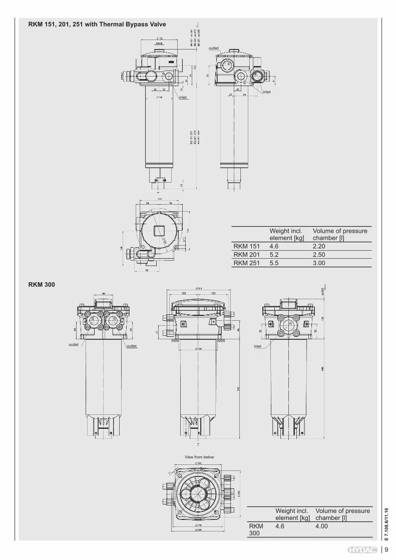
RKM 151, 201, 251 with Thermal Bypass Valve
RKM 300
Weight incl. element [kg]
Volume of pressure chamber [l]
RKM 151 4.6 2.20RKM 201 5.2 2.50RKM 251 5.5 3.00
Weight incl. element [kg]
Volume of pressure chamber [l]
RKM 300
4.6 4.00
outlet inlet
View from below
outlet
inlet
outlet
inlet
E 7.
108.
6/11
.16
10
NOTEThe information in this brochure relates to the operating conditions and applications described. For applications and operating conditions not described, please contact the relevant technical department. Subject to technical modifications.
HYDAC Filtertechnik GmbH Industriegebiet D-66280 Sulzbach/Saar Tel.: 0 68 97 / 509-01 Fax: 0 68 97 / 509-300 Internet: www.hydac.com E-Mail: [email protected]
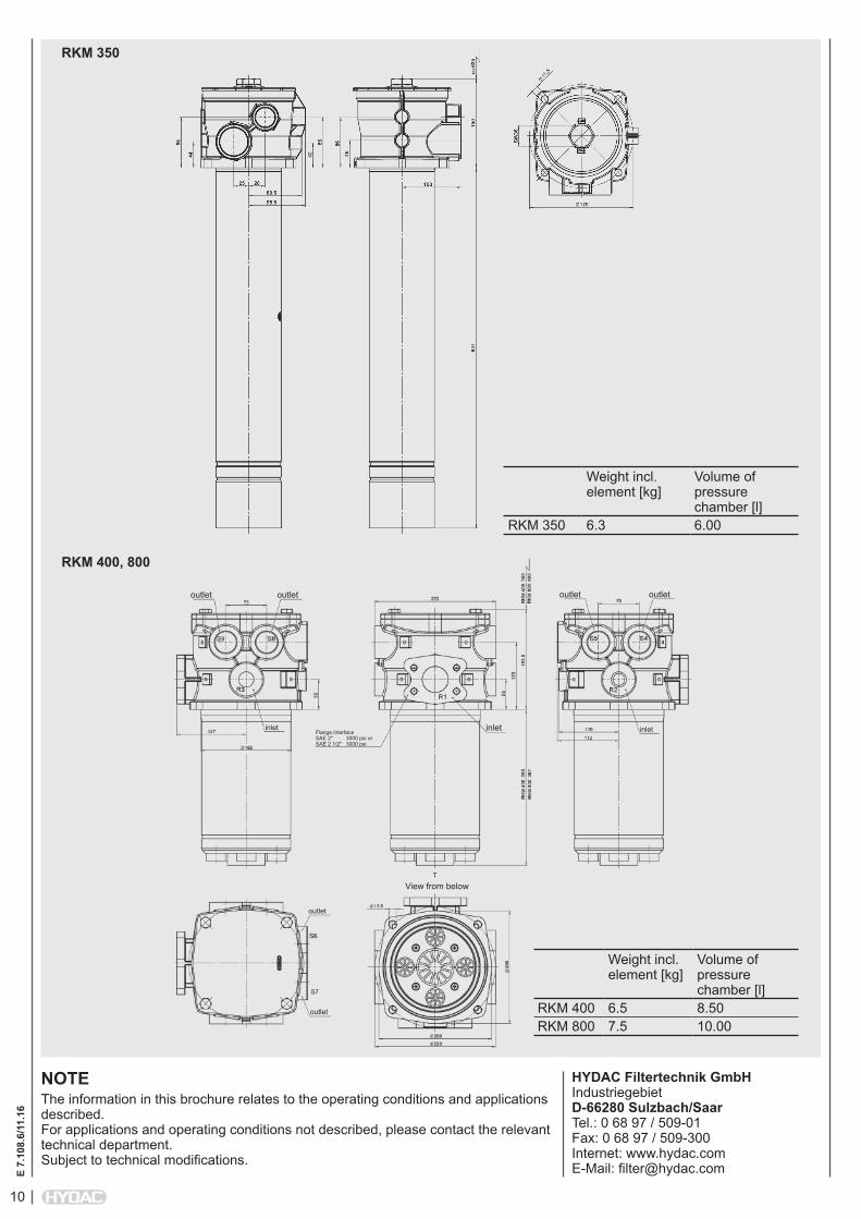
RKM 400, 800
RKM 350
Weight incl. element [kg]
Volume of pressure chamber [l]
RKM 400 6.5 8.50RKM 800 7.5 10.00
Weight incl. element [kg]
Volume of pressure chamber [l]
RKM 350 6.3 6.00
outlet
inlet
View from below
outlet outlet outlet
inletinlet
outlet
outlet
Flange interface SAE 2" 3000 psi or SAE 2 1/2" 3000 psi
Related Documents