Retro-VLC: Enabling Low-power Duplex Visible Light Communication Angli Liu University of Washington [email protected] Jiangtao Li Microsoft Research, Beijing [email protected] Guobin Shen Microsoft Research, Beijing [email protected] Chao Sun Microsoft Research, Beijing [email protected] Liqun Li Microsoft Research, Beijing [email protected] Feng Zhao Microsoft Research, Beijing [email protected] ABSTRACT The new generation of LED-based illuminating infrastruc- tures has enabled a “dual-paradigm" where LEDs are used for both illumination and communication purposes. The ubiq- uity of lighting makes visible light communication (VLC) well suited for communication with mobile devices and sen- sor nodes in indoor environment. Existing research on VLC has primarily been focused on advancing the performance of one-way communication. In this paper, we present Retro- VLC, a low-power duplex VLC system that enables a mobile device to perform bi-directional communication with the il- luminating LEDs over the same light carrier. The design fea- tures a retro-reflector fabric that backscatters light, an LCD shutter that modulates information bits on the backscattered light carrier, and several low-power optimization techniques. We have prototyped the reader system and made a few battery- free tag devices. Experimental results show that the tag can achieve a 10kbps downlink speed and 0.5kbps uplink speed over a distance of 2.4m. We also outline several potential applications of the proposed Retro-VLC system. 1. INTRODUCTION Nowadays, white LEDs have been prevalently deployed for illumination purpose for its advantageous properties such as high energy efficiency, long lifetime, environment friend- liness, to name a few. Being semiconductor devices, LEDs also possess another feature, i.e. it can be turned on and off instantaneously [22]. This effectively turns illuminat- ing LED lights into a carrier and gives rise to a new “dual- paradigm” of simultaneous illumination and visible light com- munication (VLC). The ubiquity of illuminating infrastruc- ture makes this dual-paradigm VLC (i.e., communication over existing lighting infrastructures) especially well suited for communication with mobile devices or sensor nodes such as streaming video to one’s mobile phone or collecting envi- ronmental data from home sensors. Like any communication system, it is essential to have bi- directional (i.e. both LED-to-device downlink and device- to-LED uplink) communication capability to ensure relia- bility and flexibility. For instance, a minimum requirement would be to acknowledge correct or incorrect reception of packets. One immediate solution would be using another medium such as a radio link to complement the VLC link. For instance, ByteLight [2], which exploits LED lighting in- frastructure for both communication and localization [19, 30], has resorted to Bluetooth Low Energy (BLE) for the uplink device-to-LED communication. But such solution in- curs additional cost and increased overall system complex- ity, and undermines the benefits of VLC such as security. In this paper, we are interested in a bi-directional com- munication system solely relying on VLC. An intuitive way to realize bi-directional VLC system is to put together two one-way VLC links with reverse transmitting direction, i.e. a symmetric solution. It is indeed a viable solution for dedi- cated VLC systems. It is perhaps a widely taken assumption, as existing work on VLC has primarily been focused on im- proving the throughput for one-way link using power hun- gry, expensive, dedicated sending/receiving devices and in- termediate light concentrating optical components (e.g. lenses) [7, 24, 28, 29]. However, the dual-paradigm nature of a VLC system and the practicality considerations render such symmetric solu- tion not suitable, for two basic reasons. First, the dual- paradigm VLC system, with illumination being the primary goal, has quite asymmetric capabilities at the two ends: one end is the externally powered lighting LED and the other end is the power-constrained mobile or sensor device. Sec- ondly, while the position of lights are usually fixed, that of a mobile or sensor node can be arbitrary and changing. In par- ticular, the weak end cannot afford lighting up a high power LED to transmit information especially when communicat- ing at a relative large distance (e.g. a few meters for typi- cal indoor environments). Using optical light concentrating components may allow low-power LEDs being used, but it would require precise relative positioning and careful orient- ing (with the optical components being steerable) between the two ends, and is obviously impractical. Inspired by recent work on backscatter communication systems [14, 27], in this paper, we present the design and implementation of Retro-VLC – a low-power duplex VLC 1

Welcome message from author
This document is posted to help you gain knowledge. Please leave a comment to let me know what you think about it! Share it to your friends and learn new things together.
Transcript
Retro-VLC: Enabling Low-power Duplex Visible LightCommunication
Angli LiuUniversity of Washington
Jiangtao LiMicrosoft Research, [email protected]
Guobin ShenMicrosoft Research, Beijing
Microsoft Research, [email protected]
Liqun LiMicrosoft Research, Beijing
Feng ZhaoMicrosoft Research, [email protected]
ABSTRACTThe new generation of LED-based illuminating infrastruc-tures has enabled a “dual-paradigm" where LEDs are usedfor both illumination and communication purposes. The ubiq-uity of lighting makes visible light communication (VLC)well suited for communication with mobile devices and sen-sor nodes in indoor environment. Existing research on VLChas primarily been focused on advancing the performanceof one-way communication. In this paper, we present Retro-VLC, a low-power duplex VLC system that enables a mobiledevice to perform bi-directional communication with the il-luminating LEDs over the same light carrier. The design fea-tures a retro-reflector fabric that backscatters light, an LCDshutter that modulates information bits on the backscatteredlight carrier, and several low-power optimization techniques.We have prototyped the reader system and made a few battery-free tag devices. Experimental results show that the tag canachieve a 10kbps downlink speed and 0.5kbps uplink speedover a distance of 2.4m. We also outline several potentialapplications of the proposed Retro-VLC system.
1. INTRODUCTIONNowadays, white LEDs have been prevalently deployed
for illumination purpose for its advantageous properties suchas high energy efficiency, long lifetime, environment friend-liness, to name a few. Being semiconductor devices, LEDsalso possess another feature, i.e. it can be turned on andoff instantaneously [22]. This effectively turns illuminat-ing LED lights into a carrier and gives rise to a new “dual-paradigm” of simultaneous illumination and visible light com-munication (VLC). The ubiquity of illuminating infrastruc-ture makes this dual-paradigm VLC (i.e., communicationover existing lighting infrastructures) especially well suitedfor communication with mobile devices or sensor nodes suchas streaming video to one’s mobile phone or collecting envi-ronmental data from home sensors.
Like any communication system, it is essential to have bi-directional (i.e. both LED-to-device downlink and device-to-LED uplink) communication capability to ensure relia-bility and flexibility. For instance, a minimum requirement
would be to acknowledge correct or incorrect reception ofpackets. One immediate solution would be using anothermedium such as a radio link to complement the VLC link.For instance, ByteLight [2], which exploits LED lighting in-frastructure for both communication and localization [19,30], has resorted to Bluetooth Low Energy (BLE) for theuplink device-to-LED communication. But such solution in-curs additional cost and increased overall system complex-ity, and undermines the benefits of VLC such as security.
In this paper, we are interested in a bi-directional com-munication system solely relying on VLC. An intuitive wayto realize bi-directional VLC system is to put together twoone-way VLC links with reverse transmitting direction, i.e.a symmetric solution. It is indeed a viable solution for dedi-cated VLC systems. It is perhaps a widely taken assumption,as existing work on VLC has primarily been focused on im-proving the throughput for one-way link using power hun-gry, expensive, dedicated sending/receiving devices and in-termediate light concentrating optical components (e.g. lenses)[7, 24, 28, 29].
However, the dual-paradigm nature of a VLC system andthe practicality considerations render such symmetric solu-tion not suitable, for two basic reasons. First, the dual-paradigm VLC system, with illumination being the primarygoal, has quite asymmetric capabilities at the two ends: oneend is the externally powered lighting LED and the otherend is the power-constrained mobile or sensor device. Sec-ondly, while the position of lights are usually fixed, that of amobile or sensor node can be arbitrary and changing. In par-ticular, the weak end cannot afford lighting up a high powerLED to transmit information especially when communicat-ing at a relative large distance (e.g. a few meters for typi-cal indoor environments). Using optical light concentratingcomponents may allow low-power LEDs being used, but itwould require precise relative positioning and careful orient-ing (with the optical components being steerable) betweenthe two ends, and is obviously impractical.
Inspired by recent work on backscatter communicationsystems [14, 27], in this paper, we present the design andimplementation of Retro-VLC – a low-power duplex VLC
1
Solar pannel
Retro-reflector LCD shutter
Photodiode
LED+Photodiode
Irradiation angle
Incidence angle
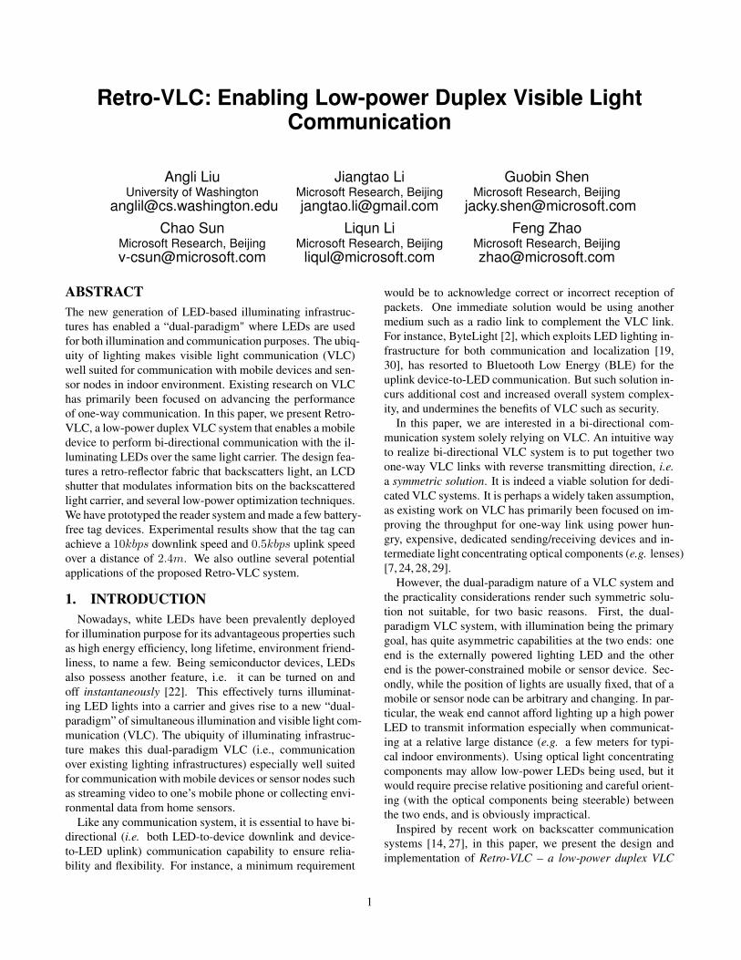
Figure 1: System architecture.
system that consists of a reader (ViReader) residing in thelighting infrastructure and tags (ViTags) integrated in mo-bile devices or sensor nodes. The ViReader is made up of anexternally powered lighting LED, a light sensor (e.g. photo-diode) and the control circuits. The ViTag consists of a lightsensor, a retro-reflective fabric, a transparent LCD shutterand the control circuits. One example tag implementation isshown in Fig. 1.
Central to Retro-VLC is the adoption of retro-reflectivefabric which retrospectively reflects light, i.e. bounces lightback to the lighting source exactly along its incoming direc-tion. Its reflecting nature helps to establish an uplink overthe same visible light channel established by the high powerlighting LED, which thus avoids using another high-powerLED on the weak end and makes it possible to achieve thelow-power design goal. Its retrospective nature further notonly allows arbitrary relative positioning between the light-ing source and the tag, but also helps to concentrate the re-flected light from a scattering light source. The two favor-able properties render Retro-VLC an effective visible lightbased backscattering communication system.
Retro-VLC works as follows. For the downlink (LED-to-tag), the LED in ViReader switches on and off at a high fre-quency (e.g. 1MHz, to avoid human perceptible flickering),turning the illuminating light into a communication carrier.Information bits are carried using certain modulation method(e.g. Manchester coding). The light signals are picked up bythe light sensor on ViTag and decoded to restore the informa-tion. For the uplink (tag-to-LED) communication, the samecarrier is leveraged via reflection. To carry bits over the re-flected light carrier, we cover the retro-reflector fabric with atransparent LCD that serves as a shutter, and adopt On-Off-Keying (OOK) modulation over the reflected light carrier bycontrolling the passing or blocking state of the LCD shutter.The modulated reflected light carrier is then picked up bya photodiode on the ViReader and decoded by a dedicatedsubsystem.
Two major challenges arose in the design of the Retro-VLC system, especially the uplink. The root causes are thepracticality considerations of the system and the low-powerrequirement of the tag. Specifically, the first challenge is
the extremely weak and noisy signal (reflected by the re-mote tag) received by at the ViReader. We use a photodiodewith wide field of view (FoV) on the ViReader to avoid con-straining the range of possible tag deployment. The wideFoV of the photodiode not only makes it less sensitive to thereflected lights (as only a tiny portion of its view actuallycorresponds to the retro-reflecting area of a tag), but alsoinvites severe interference from the leakage and ambient re-flection of the strong downlink signal and carrier. Secondly,the low power consumption requirement of ViTag (in hopeto achieve battery-free operation by only harvesting energyfrom the illuminating LED) entails careful design as well.The receiving (demodulation and decoding) unit and modu-lation unit (the LCD) on the ViTag consume significant en-ergy. The LCD shutter leverages the electric field to con-trol the arrangement of liquid crystal molecules (to polarizethe light). It itself is a capacitor. Frequent charging anddischarging the LCD consumes relatively significant energy,especially when the refresh rate is high. In addition, for sakeof cost and energy consumption, we do not use any highprecision oscillator on the ViTag. There is no clock synchro-nization between a ViReader and ViTag (s) either.
We have addressed these challenges with the followingdesign. We employ a differential amplifier in the ViReaderreceiver to filter out the noises; we adopt a multi-stage am-plification design with feedbacks for automatic gain controlto pull the system away from self-excitation. With these de-signs, we amplify the signal by up to 120dB while ensur-ing the stability of the system. We devise a sliding-windowmulti-symbol match filter to handle possible clock offsetsand drifts between the ViReader and the ViTag. To achievelow power consumption of the ViTag, we have followed theprinciples of using as much analog components as possi-ble, making the circuit work at the most energy-efficient(i.e. close to cut-off) state, and seeking maximal energyreuse. In particular, we avoid energy-demanding analog-to-digital converters (ADCs) with a specially designed com-parator. The microcontroller (MCU) in ViTag handles onlysimple tasks such as parity check and duty cycling, and thecontrol of LCD states. We further design an energy reusemodule that collects almost half of the LCD’s dischargingcurrent.
We have implemented several prototypes that demonstratethe effectiveness of our Retro-VLC design. We built battery-free ViTag device, which operates by harvesting energy fromthe incoming light. Fig. 1 depicts the architecture of a ViTag.It is the same size of a credit card, one-third of the area beingthe retro-reflector and two-thirds the polycrystalline siliconsolar cell. We made two types of ViReader, modified from anormal LED bulb and a flashlight, respectively.
We evaluate our system in locations where illuminatingLEDs are typically deployed such as office environments.We also evaluate in dark chambers for benchmark purpose.We measure the maximum communication range betweenthe LED and the ViTag with various LED illumination lev-
2
els, ViTag orientations, solar panel areas and retro-reflectorareas. Our experiments show that our 8.2cm×5.2cm ViTagprototype can achieve 10kbps downlink speed and 0.5kbpsuplink speed over distances of up to 1.7m in dark cham-bers and 2.4m in offices, under a 200µW power budget.We also demonstrate its merit in security by evaluating thearea around the ViTag in which uplink transmissions can besniffed.
Contributions: We make the following contributions:
• We propose a practical bi-directional VLC primitive thatworks for small battery-free devices using retro-reflectorsand LCDs and ordinary white LEDs. The design is wellsuited for the communication between a mobile or sensordevice and the illuminating infrastructure.• We address various challenges through energy-efficient
analog circuit design and energy reuse components onthe ViTag, and weak signal detection and unsynchronizeddecoding scheme on the ViReader.• We build and evaluate real working prototypes, confirm
the effectiveness of our design and provide a sense of itspracticality.
2. RELATED WORKOur work is related to prior work in VLC systems and
backscatter communication systems:
(a) VLC Systems: Recently, there have been many effortsexploring communication mediums wherein visible lightscarry information. These work, however, either deal withonly one-way communication without an uplink [10, 17, 20,33], or go in a two-way fashion with both sides suppliedby battery [9, 13, 21], which limit real-world practicality.Specifically, LED-to-phone systems [19, 22, 30] only sup-port downlink transmissions, targeted at phone localization.LED-to-LED systems [31,34] consider visible light networks,where each end is not meant to be mobile, and is not battery-free. By contrast, our work augments the existing systemswith an additional uplink channel from the mobile device tothe LED on the same band as the downlink, with an empha-sis on the low power design and system robustness.
(b) Backscatter Systems: Backscattering is a way to pro-vide transmission capability for extremely low-power de-vices, substituting the need for devices actively generatingsignals. The technique has been primarily used by RFIDtags [15, 32]. Recently, Wi-Fi [16] and TV-based [23, 27]systems started employing and advancing this technique.
Our Retro-VLC system also achieves low-energy designusing backscattering and further shares design principles with[16, 23, 27], that is, using analog components on the energy-constrained end. The major differences lie in the fact that weare dealing with visible light using a retro-reflector, whereasthe ambient backscatter systems are backscattering radio waves.On the tag side, we use a light sensor to receive and a retro-reflector to send (by reflection) information, which is alsodifferent from the shared antenna and RF front-end in other
(a) Corner Cube Illustration
(b)
(c)
(d)
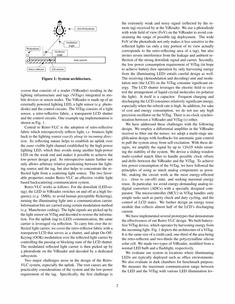
Figure 2: Illustration of the reflection principle of aretro-reflector (a), and the comparison of the reflectionproperty (b)-(d). The flash and camera are at positionsof (90◦, 90◦), (45◦, 90◦) and (45◦, 45◦) in (b), (c), and(d), respectively. The three side-by-side put testing ma-terials are, from left to right, white paper, mirror andretro-reflector fabric.
backscattering systems. In comparison, we can easily achievefull-duplex while other systems are essentially half-duplexand require intensive tricks and significant overhead to achievefull-duplex [5, 8, 12].
In addition, because of the backscattering nature, thesewireless systems tend to expose their transmissions to a widesurrounding area, leaving a good chance for side readers tooverhear the information being transmitted [16, 23, 27]. Bycontrast, ViTag relies on visible light communication, whichimplies that eavesdroppers are easily discernible. The use ofretro-reflectors further constraints the uplink transmission tostick along the tag-reader path. As a result, our system ViTagcomes with a good security property inherently, while othersystems have to enhance their security with extra efforts [25,35].
3. PRELIMINARIESOur goal is to establish a bi-directional communication
link using visible lights. As the dual-paradigm nature ofVLC over the lighting infrastructure entails that the primaryfunction is illumination and the primary usage scenario iscommunicating with low power mobile devices or sensornodes, we have the following two basic requirements behindthe goal.
• Efficiency Requirement: Establish a low-power, du-plex visible light communication link with a battery-freemobile end that harvests light energy from the illumina-tion LED.
• Practicality Requirement: Impose no constraints onactual use. This implies a practical working range in nor-mal indoor situations, flexible tag orientation, and that thesize of the device be small.
To achieve a duplex link on visible light, one possibilityis to employ a symmetric design, that is, using an LED onthe mobile device or sensor node to actively emit signals,
3
and pick up the signals with a light sensor on the illuminat-ing LED. Unfortunately, reaching a practical working dis-tance (with the light typically installed on the ceiling) costsprohibitively high energy on the mobile or sensor device.The light energy attenuates quickly as the propagation pro-ceeds [6].
One way to extend the communication range is to use di-rectional signals, ideally a laser, or using intermediate lightconcentrating optical components (e.g. lenses). However,that would require careful alignment between the light sourceand the mobile device, which may further require steerableoptical components and precise tag positioning. Thus, it isnot quite applicable.
Another possible way towards more affordable power is toleverage the light from the illuminating infrastructure, whichis usually of high power. This is similar to the design of pas-sive RFID systems where a tag communicates with a readerby reflecting the incoming radio signal. For instance, reflect-ing the light using a mirror to a light sensor that sits besidethe LED uses this principle. However, use of a mirror wouldthen require carefully orienting the mobile device, thus vi-olating the practicality requirement. Inspired by free spacelaser communication systems [3], we use a retro-reflectorto meet both requirements. Below we introduce the retro-reflector and present some favorable properties about retro-reflector materials.
Retro-reflector: A retro-reflector is a device or surfacethat, unlike mirrors, reflects light back to its source along thesame incoming direction with little scattering [4]. A retro-reflector can be produced using spherical lens, much like themechanism of a cat’s eye. A more feasible way to obtainretro-reflection is to use a corner reflector, which consists ofa set of corner cubes each with three mutually perpendicularreflective surfaces. The principle of such a retro-reflector isshown in Fig. 2(a). A large yet relatively thin retro-reflectoris possible by combining many small corner reflectors, usingthe standard triangular tiling. Cheap retro-reflector fabric arereadily available, e.g. the Scotchlite series from 3M [1], andare widely used on road signs, bicycles, and clothing for traf-fic safety at night.
We conduct experiments to measure the reflecting prop-erties of a retro-reflector fabric (Scotchlite 9910 from 3M).We compare it against a plain white paper which featuresdiffusing reflection and a planar mirror that does mirror re-flection. We place the three materials side by side and letthe light source (a flash light) emit light at different angleswhile in the same distance from the materials. We capturethe reflection effects with a camera from multiple angles.Fig. 2(b)-(d) shows the resulting images from experimentsconducted in a dark chamber. In the figures, we can see thatthe retro-reflector fabric is bright as long as the light sourceand the camera are along the same direction, be it 45◦ or 90◦,whereas the mirror is bright only when both the camera andthe flash are at 90◦. In the case of Fig. 2(c), the images of themirror and the retro-reflector are dark. On the contrary, the
white paper is always slightly turned on because of its diffu-sion, despite the flash and camera positions. We notice thatthe brightness of the retro-reflector fabric tends to be weakerthan that of the mirror but more uniform. This is because thefabric we used is not a perfect retro-reflector and has smalldispersion [1].
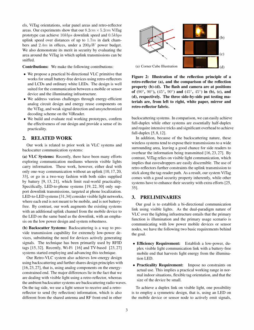
The ability to bounce back light from any incidence angleleads to a favorable property of the retro-reflector: when thelight source emits omni-directional lights, the retro-reflectorwill concentrate the lights as it reflects them. This is illus-trated in Fig. 3(a). From experiments, we empirically foundthat the concentrated energy is directly proportional to thesize of the retro-reflector fabric, as shown in Fig. 3(b).
Emitted light ray
Reflected light ray
Retro-
reflector
(a) Energy Concentration
−5 0 5 10 15 20 25 30Retro-reflector area (cm^2)
−0.2
0.0
0.2
0.4
0.6
0.8
1.0
1.2
Norm
aliz
ed R
eflect
ion E
nerg
y
(b) Reflected Energy vs. Area
Figure 3: Energy concentrating property of a retro-reflector when the light source emits omni-directionallights and the relationship between reflected energy andthe retro-reflector size.
Modulating with LCD: In terms of embedding informa-tion bits on the reflected light, special retro-reflector canalter the amplitude by electronically controlling the reflec-tion or absorption using, for example, MEMS technologies[28, 29]. However, we hope to use ordinary, off-the-shelfretro-reflector fabrics. In order to modulate the lights re-flected by such fabric, we resort to a liquid crystal displaythat can pass or block light under the control of the electricalfield.
(a) LCD Principle [35]
VCC
LCD Rdischarge
Control Pin
Charging
Path
Dis
cha
rgin
g
Pa
th
(b) LCD Driver
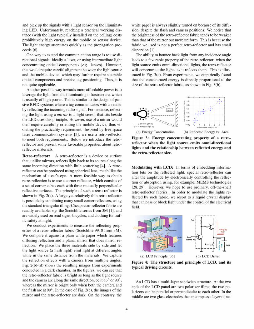
Figure 4: The structure and principle of LCD, and itstypical driving circuits.
An LCD has a multi-layer sandwich structure. At the twoends of the LCD panel are two polarizer films; the two po-larizers can be parallel or perpendicular to each other. In themiddle are two glass electrodes that encompass a layer of ne-
4
Downlink
Uplink
Half-duplex
Full-duplex
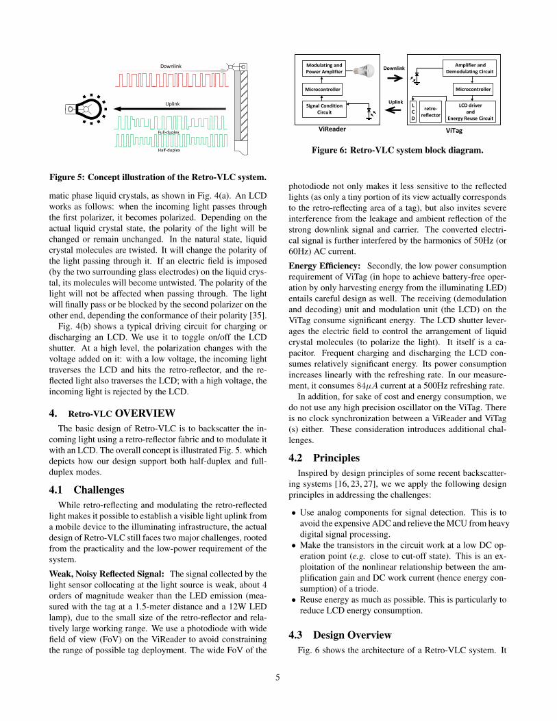
Figure 5: Concept illustration of the Retro-VLC system.
matic phase liquid crystals, as shown in Fig. 4(a). An LCDworks as follows: when the incoming light passes throughthe first polarizer, it becomes polarized. Depending on theactual liquid crystal state, the polarity of the light will bechanged or remain unchanged. In the natural state, liquidcrystal molecules are twisted. It will change the polarity ofthe light passing through it. If an electric field is imposed(by the two surrounding glass electrodes) on the liquid crys-tal, its molecules will become untwisted. The polarity of thelight will not be affected when passing through. The lightwill finally pass or be blocked by the second polarizer on theother end, depending the conformance of their polarity [35].
Fig. 4(b) shows a typical driving circuit for charging ordischarging an LCD. We use it to toggle on/off the LCDshutter. At a high level, the polarization changes with thevoltage added on it: with a low voltage, the incoming lighttraverses the LCD and hits the retro-reflector, and the re-flected light also traverses the LCD; with a high voltage, theincoming light is rejected by the LCD.
4. Retro-VLC OVERVIEWThe basic design of Retro-VLC is to backscatter the in-
coming light using a retro-reflector fabric and to modulate itwith an LCD. The overall concept is illustrated Fig. 5. whichdepicts how our design support both half-duplex and full-duplex modes.
4.1 ChallengesWhile retro-reflecting and modulating the retro-reflected
light makes it possible to establish a visible light uplink froma mobile device to the illuminating infrastructure, the actualdesign of Retro-VLC still faces two major challenges, rootedfrom the practicality and the low-power requirement of thesystem.
Weak, Noisy Reflected Signal: The signal collected by thelight sensor collocating at the light source is weak, about 4orders of magnitude weaker than the LED emission (mea-sured with the tag at a 1.5-meter distance and a 12W LEDlamp), due to the small size of the retro-reflector and rela-tively large working range. We use a photodiode with widefield of view (FoV) on the ViReader to avoid constrainingthe range of possible tag deployment. The wide FoV of the
Uplink
Downlink
Signal Condition Circuit
Microcontroller
Modulating and Power Amplifier
LCD driver and
Energy Reuse Circuit
Microcontroller
Amplifier and Demodulating Circuit
LCD
retro-reflector
ViReader ViTag
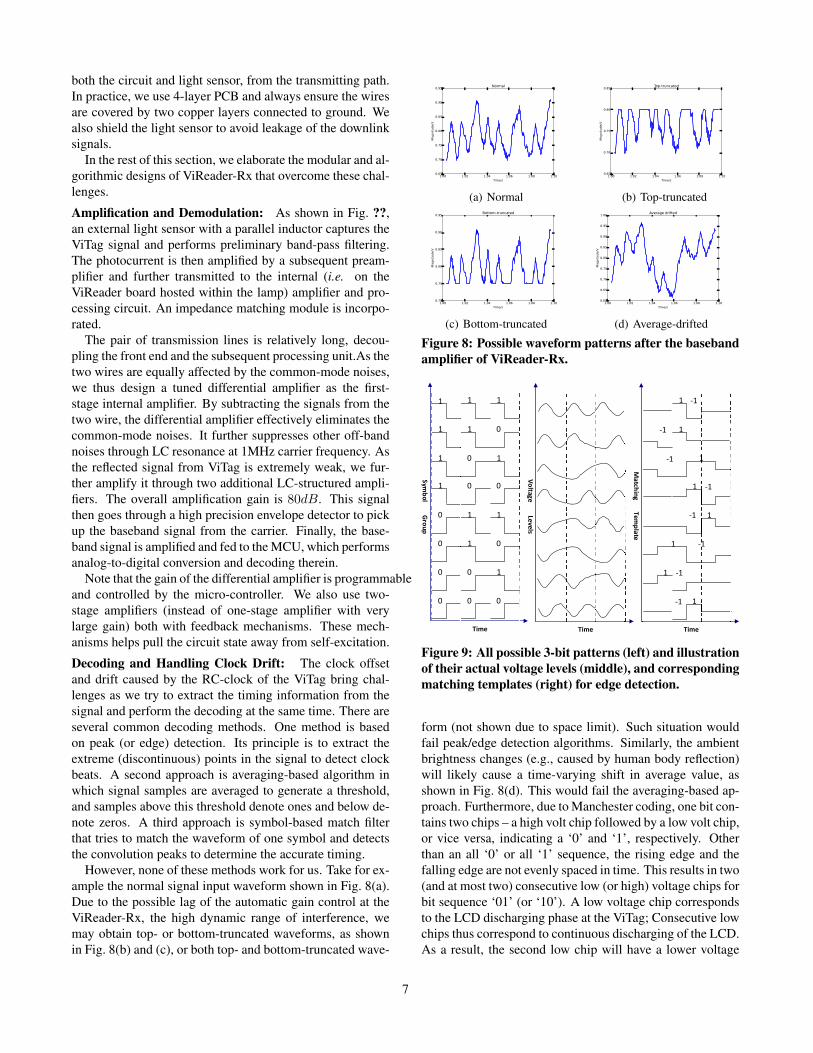
Figure 6: Retro-VLC system block diagram.
photodiode not only makes it less sensitive to the reflectedlights (as only a tiny portion of its view actually correspondsto the retro-reflecting area of a tag), but also invites severeinterference from the leakage and ambient reflection of thestrong downlink signal and carrier. The converted electri-cal signal is further interfered by the harmonics of 50Hz (or60Hz) AC current.
Energy Efficiency: Secondly, the low power consumptionrequirement of ViTag (in hope to achieve battery-free oper-ation by only harvesting energy from the illuminating LED)entails careful design as well. The receiving (demodulationand decoding) unit and modulation unit (the LCD) on theViTag consume significant energy. The LCD shutter lever-ages the electric field to control the arrangement of liquidcrystal molecules (to polarize the light). It itself is a ca-pacitor. Frequent charging and discharging the LCD con-sumes relatively significant energy. Its power consumptionincreases linearly with the refreshing rate. In our measure-ment, it consumes 84µA current at a 500Hz refreshing rate.
In addition, for sake of cost and energy consumption, wedo not use any high precision oscillator on the ViTag. Thereis no clock synchronization between a ViReader and ViTag(s) either. These consideration introduces additional chal-lenges.
4.2 PrinciplesInspired by design principles of some recent backscatter-
ing systems [16, 23, 27], we we apply the following designprinciples in addressing the challenges:
• Use analog components for signal detection. This is toavoid the expensive ADC and relieve the MCU from heavydigital signal processing.• Make the transistors in the circuit work at a low DC op-
eration point (e.g. close to cut-off state). This is an ex-ploitation of the nonlinear relationship between the am-plification gain and DC work current (hence energy con-sumption) of a triode.• Reuse energy as much as possible. This is particularly to
reduce LCD energy consumption.
4.3 Design OverviewFig. 6 shows the architecture of a Retro-VLC system. It
5

consists of a ViReader and a ViTag. The ViReader resides onthe lighting infrastructure, consisting of an illumination LEDand transmission logic (termed ViReader-Tx hereafter), alight sensor and the subsequent receiving circuit (ViReader-Rx). The ViTag consists of a light sensor and receiving cir-cuits (ViTag-Rx), and a retro-reflector, a modulating LCDand other circuitry components (ViTag-Tx). The ViReader-Tx and ViTag-Rx together make the downlink visible lightchannel, and the ViTag-Tx and ViReader-Rx together makethe uplink. Retro-VLC operates as follows:
Downlink: For the downlink communication, the ViReadersends out information by modulating the carrier using On/OffKeying (OOK) and employing Manchester coding. This sig-nal is captured by the light sensor of ViTag, amplified, de-modulated and decoded by ViTag-Rx in analog domain.
Uplink: As for the uplink communication, the MCU onthe ViTag controls the LCD to modulate the light carrier re-flected by the retro-reflector fabric. The reflected light trav-els back to the light sensor that collocates with the LED.Upon capture, the weak signal is first amplified with a dif-ferential amplifier to mitigate noises, further amplified, de-modulated, digitized and finally decoded. Special logic hasbeen designed to account for the possible clock drift at theViTag when modulating the reflected carrier as we have useda cheap RC oscillator to avoid high energy cost and overlylarge size of crystal oscillators.
The downlink and uplink can work concurrently on theirrespective bands. Hence it is capable of full-duplexing. Nor-mally, when there is no traffic, the ViReader-Tx sends outthe carrier by switching the LED light at a high frequencyf0, which should be fast enough to avoid perceivable flick-ering (i.e., f0 � 200Hz). In our implementation, we set f0to 1MHz. We support dimming of the LED by changing itsDC bias. Both the receiving logic on ViReader and ViTag(when turned on) keep on monitoring their own incominglight channel. With this design, a ViTag can initiate the com-munication to the ViReader. An alternative design would beturning on the ViTag-Tx only when ViTag receives certaininformation. This is the half-duplexing mode where onlythe ViReader can initiate a communication session, similarto how existing RFID system works.
5. Retro-VLC SYSTEM DESIGNIn this section, we describe our design of Retro-VLC in
more detail. Retro-VLC consists of a ViReader and a ViTag,each of which contains the transmitting and receiving logic.We elaborate their design one by one, starting with the trans-mitter of the ViReader. Its detailed diagram is shown inFig. 7.
5.1 ViReader-Tx DesignThe ViReader-Tx employs a standard VLC design as in
other work: it performs encoding using an MCU and tog-gles the LED light to control the power amplifier. Specifi-
cally, we employ a 1MHz carrier and perform on-off keying(OOK) and Manchester coding. The communication band-width we use is 10kHz.
Note that we may use even higher carrier frequency andlarger communication bandwidth. We made the choice dueto the limitation of ordinary commercial off-the-shelf LEDwe have. If we toggle at a faster rate, the amplitude differ-ence between On and Off state will be too small to serve asan effective carrier. We use 10kHz bandwidth as it sufficesapplications we have in mind, e.g., send back the tag ID andcertain sensor information it may carry.
LED
MicroController (Cortex M4 based) Power Amplifier
Preamplifier 2 Stage Tuned
Amplifier
1MHz
Sliding Window Match Decoder
Encoding and Transmitting
Logic
Automatic Gain Control
ADC
TX-RX Isolator
Programmable-Gain Differential Amplifier
Baseband Amplifier
Precision RectifierDemodulator
Figure 7: Circuit diagram of ViReader.
5.2 ViReader-Rx DesignThe major challenges that arise in the design of the ViReader-
Rx are the following. First of all, the signal from the ViTagreflection is extremely weak, especially due to the use ofthe small retro-reflector on the ViTag. Second, the signalis severely interfered by other light and electrical sources.In particular, as the light sensor sits next to the LED, it islikely that there is leakage from downlink signals and car-rier, in additional to the diffusing reflections from the ambi-ent sources. Because of the close distance, the interference isseveral orders of magnitude greater than the actual reflectedsignal from the ViTag. As measured in one implementationof 12W LED lamp, the power of the ViTag-reflected sig-nal is about −80dBm at 1.5 meters while the ViReader-Txemitted light signal can be up to 30dBm. In fact, these inter-ference could cause the ViReader-Rx amplifiers to saturatewithout careful design. In practice, the light reflected by themovement of humans and other objects around also causessuch interference. Thirdly, the converted electrical signal isalso interfered by commercial FM radios that operate around1MHz. The harmonics of the 50 − 60Hz AC supply of thelighting infrastructure also matters, which is on par with thetoggling rate (0.5kHz) of our LCD modulator. Last but notthe least, our choice of using a small and low frequency RCoscillator at the ViTag, instead of high-precision oscillator(for sake of energy consumption reduction), makes the re-flected signal suffer from clock offsets and drifts.
In our design, we first try to isolate the receiving path,
6
both the circuit and light sensor, from the transmitting path.In practice, we use 4-layer PCB and always ensure the wiresare covered by two copper layers connected to ground. Wealso shield the light sensor to avoid leakage of the downlinksignals.
In the rest of this section, we elaborate the modular and al-gorithmic designs of ViReader-Rx that overcome these chal-lenges.
Amplification and Demodulation: As shown in Fig. ??,an external light sensor with a parallel inductor captures theViTag signal and performs preliminary band-pass filtering.The photocurrent is then amplified by a subsequent pream-plifier and further transmitted to the internal (i.e. on theViReader board hosted within the lamp) amplifier and pro-cessing circuit. An impedance matching module is incorpo-rated.
The pair of transmission lines is relatively long, decou-pling the front end and the subsequent processing unit.As thetwo wires are equally affected by the common-mode noises,we thus design a tuned differential amplifier as the first-stage internal amplifier. By subtracting the signals from thetwo wire, the differential amplifier effectively eliminates thecommon-mode noises. It further suppresses other off-bandnoises through LC resonance at 1MHz carrier frequency. Asthe reflected signal from ViTag is extremely weak, we fur-ther amplify it through two additional LC-structured ampli-fiers. The overall amplification gain is 80dB. This signalthen goes through a high precision envelope detector to pickup the baseband signal from the carrier. Finally, the base-band signal is amplified and fed to the MCU, which performsanalog-to-digital conversion and decoding therein.
Note that the gain of the differential amplifier is programmableand controlled by the micro-controller. We also use two-stage amplifiers (instead of one-stage amplifier with verylarge gain) both with feedback mechanisms. These mech-anisms helps pull the circuit state away from self-excitation.
Decoding and Handling Clock Drift: The clock offsetand drift caused by the RC-clock of the ViTag bring chal-lenges as we try to extract the timing information from thesignal and perform the decoding at the same time. There areseveral common decoding methods. One method is basedon peak (or edge) detection. Its principle is to extract theextreme (discontinuous) points in the signal to detect clockbeats. A second approach is averaging-based algorithm inwhich signal samples are averaged to generate a threshold,and samples above this threshold denote ones and below de-note zeros. A third approach is symbol-based match filterthat tries to match the waveform of one symbol and detectsthe convolution peaks to determine the accurate timing.
However, none of these methods work for us. Take for ex-ample the normal signal input waveform shown in Fig. 8(a).Due to the possible lag of the automatic gain control at theViReader-Rx, the high dynamic range of interference, wemay obtain top- or bottom-truncated waveforms, as shownin Fig. 8(b) and (c), or both top- and bottom-truncated wave-
1.00 1.02 1.04 1.06 1.08 1.10Time/s
0.65
0.70
0.75
0.80
0.85
0.90
0.95
Magnitude/V
Normal
(a) Normal
1.00 1.02 1.04 1.06 1.08 1.10Time/s
0.65
0.70
0.75
0.80
0.85
Magnitude/V
Top-truncated
(b) Top-truncated
1.00 1.02 1.04 1.06 1.08 1.10Time/s
0.70
0.75
0.80
0.85
0.90
0.95
Magnitude/V
Bottom-truncated
(c) Bottom-truncated
1.00 1.02 1.04 1.06 1.08 1.10Time/s
0.60
0.65
0.70
0.75
0.80
0.85
0.90
0.95
1.00
Magnitude/V
Average drifted
(d) Average-drifted
Figure 8: Possible waveform patterns after the basebandamplifier of ViReader-Rx.
Time
Ma
tch
ing
T
em
pla
te
-11
1
1
1
-1
-1
-1
1 -1
-1 1
1 -1
1-1
Time
Sym
bo
l G
rou
p
0 0 0
0
0 0 1
0
0 0
0
1
0
1
1
1
1
1
1 1
1
01
1
Time
Vo
ltag
e
Le
ve
ls
Figure 9: All possible 3-bit patterns (left) and illustrationof their actual voltage levels (middle), and correspondingmatching templates (right) for edge detection.
form (not shown due to space limit). Such situation wouldfail peak/edge detection algorithms. Similarly, the ambientbrightness changes (e.g., caused by human body reflection)will likely cause a time-varying shift in average value, asshown in Fig. 8(d). This would fail the averaging-based ap-proach. Furthermore, due to Manchester coding, one bit con-tains two chips – a high volt chip followed by a low volt chip,or vice versa, indicating a ‘0’ and ‘1’, respectively. Otherthan an all ‘0’ or all ‘1’ sequence, the rising edge and thefalling edge are not evenly spaced in time. This results in two(and at most two) consecutive low (or high) voltage chips forbit sequence ‘01’ (or ‘10’). A low voltage chip correspondsto the LCD discharging phase at the ViTag; Consecutive lowchips thus correspond to continuous discharging of the LCD.As a result, the second low chip will have a lower voltage
7
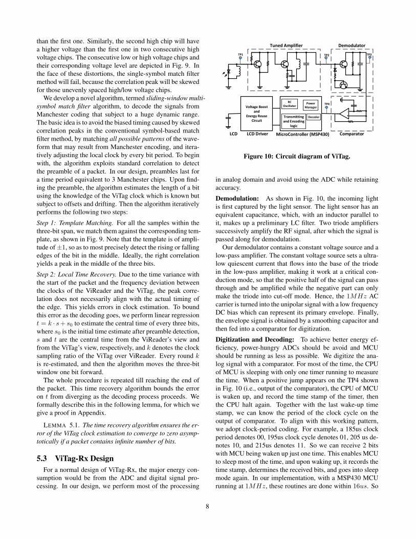
than the first one. Similarly, the second high chip will havea higher voltage than the first one in two consecutive highvoltage chips. The consecutive low or high voltage chips andtheir corresponding voltage level are depicted in Fig. 9. Inthe face of these distortions, the single-symbol match filtermethod will fail, because the correlation peak will be skewedfor those unevenly spaced high/low voltage chips.
We develop a novel algorithm, termed sliding-window multi-symbol match filter algorithm, to decode the signals fromManchester coding that subject to a huge dynamic range.The basic idea is to avoid the biased timing caused by skewedcorrelation peaks in the conventional symbol-based matchfilter method, by matching all possible patterns of the wave-form that may result from Manchester encoding, and itera-tively adjusting the local clock by every bit period. To beginwith, the algorithm exploits standard correlation to detectthe preamble of a packet. In our design, preambles last fora time period equivalent to 3 Manchester chips. Upon find-ing the preamble, the algorithm estimates the length of a bitusing the knowledge of the ViTag clock which is known butsubject to offsets and drifting. Then the algorithm iterativelyperforms the following two steps:
Step 1: Template Matching. For all the samples within thethree-bit span, we match them against the corresponding tem-plate, as shown in Fig. 9. Note that the template is of ampli-tude of±1, so as to most precisely detect the rising or fallingedges of the bit in the middle. Ideally, the right correlationyields a peak in the middle of the three bits.
Step 2: Local Time Recovery. Due to the time variance withthe start of the packet and the frequency deviation betweenthe clocks of the ViReader and the ViTag, the peak corre-lation does not necessarily align with the actual timing ofthe edge. This yields errors in clock estimation. To boundthis error as the decoding goes, we perform linear regressiont = k · s+ s0 to estimate the central time of every three bits,where s0 is the initial time estimate after preamble detection,s and t are the central time from the ViReader’s view andfrom the ViTag’s view, respectively, and k denotes the clocksampling ratio of the ViTag over ViReader. Every round kis re-estimated, and then the algorithm moves the three-bitwindow one bit forward.
The whole procedure is repeated till reaching the end ofthe packet. This time recovery algorithm bounds the erroron t from diverging as the decoding process proceeds. Weformally describe this in the following lemma, for which wegive a proof in Appendix.
LEMMA 5.1. The time recovery algorithm ensures the er-ror of the ViTag clock estimation to converge to zero asymp-totically if a packet contains infinite number of bits.
5.3 ViTag-Rx DesignFor a normal design of ViTag-Rx, the major energy con-
sumption would be from the ADC and digital signal pro-cessing. In our design, we perform most of the processing
Demodulator
Comparator
Voltage Boost and
Energy Reuse Circuit
LCD
-+
MicroController (MSP430)LCD Driver
Tuned Amplifier
Power Manager
RC Oscillator
DecoderTransmitting and Encoding
logic
TP1 TP2
TP4
TP3
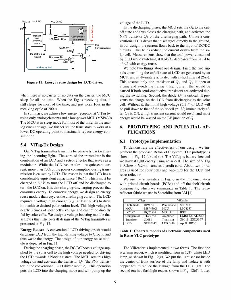
Figure 10: Circuit diagram of ViTag.
in analog domain and avoid using the ADC while retainingaccuracy.
Demodulation: As shown in Fig. 10, the incoming lightis first captured by the light sensor. The light sensor has anequivalent capacitance, which, with an inductor parallel toit, makes up a preliminary LC filter. Two triode amplifierssuccessively amplify the RF signal, after which the signal ispassed along for demodulation.
Our demodulator contains a constant voltage source and alow-pass amplifier. The constant voltage source sets a ultra-low quiescent current that flows into the base of the triodein the low-pass amplifier, making it work at a critical con-duction mode, so that the positive half of the signal can passthrough and be amplified while the negative part can onlymake the triode into cut-off mode. Hence, the 1MHz ACcarrier is turned into the unipolar signal with a low frequencyDC bias which can represent its primary envelope. Finally,the envelope signal is obtained by a smoothing capacitor andthen fed into a comparator for digitization.
Digitization and Decoding: To achieve better energy ef-ficiency, power-hungry ADCs should be avoid and MCUshould be running as less as possible. We digitize the ana-log signal with a comparator. For most of the time, the CPUof MCU is sleeping with only one timer running to measurethe time. When a positive jump appears on the TP4 shownin Fig. 10 (i.e., output of the comparator), the CPU of MCUis waken up, and record the time stamp of the timer, thenthe CPU halt again. Together with the last wake-up timestamp, we can know the period of the clock cycle on theoutput of comparator. To align with this working pattern,we adopt clock-period coding. For example, a 185us clockperiod denotes 00, 195us clock cycle denotes 01, 205 us de-notes 10, and 215us denotes 11. So we can receive 2 bitswith MCU being waken up just one time. This enables MCUto sleep most of the time, and upon waking up, it records thetime stamp, determines the received bits, and goes into sleepmode again. In our implementation, with a MSP430 MCUrunning at 1MHz, these routines are done within 16us. So
8
BQ25504
and
Appending
circuits
Discharge Pin
D0
1.0 M
2.2 M
1.0 M
Q1
1.0 M
VSolar Cell (1.8~2.6V) VLCD (5.5V)
VLCD (5.5V)
LCD
9nF Equivalent
DC-DC Step-up
Circuit
LCD Control PinConventional
LCD driver
Discharging Path
Ch
arg
ing
Pa
th
Q0
Figure 11: Energy reuse design for LCD driver.
when there is no carrier or no data on the carrier, the MCUsleep for all the time. When the Tag is receiving data, itstill sleeps for most of the time, and just work 16us in thereceiving cycle of 200us.
In summary, we achieve low energy reception at ViTag byusing only analog elements and a low-power MCU (MSP430).The MCU is in sleep mode for most of the time. In the ana-log circuit design, we further set the transistors to work at alower DC operating point to maximally reduce energy con-sumption.
5.4 ViTag-Tx DesignOur ViTag transmitter transmits by passively backscatter-
ing the incoming light. The core of the transmitter is thecombination of an LCD and a retro-reflector that serves as amodulator. While the LCD has an ultra low quiescent cur-rent, more than 70% of the power consumption during trans-mission is caused by LCD. The reason is that the LCD has aconsiderable equivalent capacitance ( 9nF ), which must becharged to 5.5V to turn the LCD off and be discharged toturn the LCD on. It is this charging-discharging process thatconsumes energy. To conserve energy, we design an energyreuse module that recycles the discharging current. The LCDrequires a voltage high enough (e.g. at least 5.5V ) to driveit to achieve desired polarization level. This high voltage isnearly 3 times of solar cell’s voltage and cannot be directlyfed by solar cells. We design a voltage boosting module thatachieves this. The overall design of the ViTag transmitter ispresented in Fig. ??.
Energy Reuse: A conventional LCD driving circuit woulddischarge LCD from the high driving voltage to Ground andthus waste the energy. The design of our energy reuse mod-ule is depicted in Fig. 11.
During the charging phase, the DC/DC boosts voltage sup-plied by the solar cell to the high voltage needed for drivingthe LCD towards a blocking state. The MCU sets this highvoltage on and activates the transistor Q0 (the PNP transis-tor in the conventional LCD driver module). This operationputs the LCD into the charging mode and will pump up the
voltage of the LCD.In the discharging phase, the MCU sets the Q0 to the cut-
off state and thus closes the charging path, and activates theNPN transistor Q1 on the discharging path. Unlike a con-ventional LCD driver that discharges directly to the ground,in our design, the current flows back to the input of DC/DCcircuits. This helps reduce the current drawn from the so-lar cell. Measurements show that the total power consumedby LCD while switching at 0.5kHz decreases from 84uA to46uA with energy reuse.
We note two things about our design. First, the two sig-nals controlling the on/off state of LCD are generated by anMCU, and is alternately activated with a short interval (2us).This ensures only one transistor of Q0 and Q1 is open ata time and avoids the transient high current that would becaused if both semi-conductive transistors are activated dur-ing the switching. Second, the diode D0 is critical. It pre-vents the charge on the LCD from discharging to the solarcell. Without it, the initial high voltage (5.5V ) of LCD willbe pull down to that of the solar cell (2.1V ) immediately af-ter Q1 is ON, a high transient current would result and mostenergy would be wasted on the BE junction of Q1.
6. PROTOTYPING AND POTENTIAL AP-PLICATIONS
6.1 Prototype ImplementationTo demonstrate the effectiveness of our design, we im-
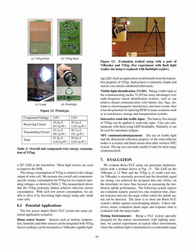
plement the proposed Retro-VLC system. Our prototype isshown in Fig. 12 (a) and (b). The ViTag is battery-free andwe harvest light energy using solar cell. The size of ViTagis 8.2cm × 5.2cm, same as a credit card. About two-thirdsarea is used for solar cells and one-third for the LCD andretro-reflector.
We use the schematics in Fig. 6 in the implementationwith printed circuit boards (PCBs) and off-the-shelf circuitcomponents, which we summarize in Table 1. The retro-reflector fabric we use is Scotchlite from 3M [1].
ViTag ViReaderPhotodiode BPW34 Photodiode SFH213MCU MSP430G MCU LPC4357DC/DC BQ25504 MOSFET IRF510Comparator TLV2762 Amplifier LM6172, AD620Transistor S9018 Transistor S9018, 2SC3357LCD SF110147 LED Bulb Apollo BR30
Table 1: Concrete models of electronic components usedin Retro-VLC prototype
The ViReader is implemented in two forms. The first oneis a lamp reader, which is modified from an 12W white LEDlamp, as shown in Fig. 12(c). We put the light sensor insidethe center of front surface of the lamp and isolate it withcopper foil to reduce the leakage from the LED light. Thesecond one is a flashlight reader, shown in Fig. 12(d). It uses
9
(a) ViTag Front (b) ViTag Back
(c) Lamp (d) Flashlight
Figure 12: Prototype.
Component\Voltage 2.0V 2.6V
Receiving Circuit 43.8µA 48.4µA(87.6µW ) (125.8µW )
Transmitting Circuit 45.1µA 36.7µA(90.2µW ) (95.4µW )
Total 91.9µA 90.0µA(183.8µW ) (234.0µW )
Table 2: Overall and component-wise energy consump-tion of ViTag.
a 3W LED as the transmitter. Three light sensors are usedto improve the SNR.
The energy consumption of ViTag is related to the voltageoutput of solar cell. We measure the overall and component-specific energy consumption for ViTag for two typical oper-ating voltages, as shown in Table 2. The measurement showsthat the ViTag prototype indeed achieves ultra-low powerconsumption. With such low power consumption, we areable to drive it by harvesting light energy using only smallsolar cells.
6.2 Potential ApplicationsThe low power duplex Retro-VLC system has many po-
tential application scenarios.
Home sensor bearer: Sensors such as motion, tempera-ture, humidity and other sensors can be integrated with ViTag.Sensor readings can be streamed to a ViReader-capable light-
Figure 13: Evaluation testbed setup with a pair ofViReader and ViTag (For experiment with flash lightreader, the lamp is replaced with flashlight reader).
ing LED. Such an application would benefit from the battery-free property of ViTag: deployment is extremely simple andsensors can remain untethered afterwards.
Visible-light identification (VLID): Taking visible light asthe communicating media, VLID has many advantages overradio-frequency based identification systems, such as canachieve distant communication with battery free Tags, im-mune to electromagnetic interference, and more secure, thusit has the potential of replacing RFID in many scenarios suchas in warehouses, storage and transportation systems.
Interactive road side traffic signs: The battery-free designof ViTag can be applied to road-side signs. Cars can com-municate with them using LED headlights. Similarly, it canbe used for automatic tollgate.
NFC communication/payment: The use of visible lightand the directional reflection property of the retro-reflectormakes it a securer and faster means than other wireless NFCsystem. The tag size can made smaller if only for short rangecommunication.
7. EVALUATIONWe evaluate Retro-VLC using our prototype implemen-
tation with a testbed shown in Fig. 13. The LED on theViReader is 12 Watt and the ViTag is of credit card size.As ViReader is externally powered and the downlink signalare strong, (we achieved the designed data rate 10kbps onthe downlink) we have thus focused on measuring the bot-tleneck uplink performance. The following system aspectsare evaluated, namely, packet loss rate, response time, chan-nel response and also the angle within which the uplink sig-nal can be detected. The latter is to show the Retro-VLCsystem’s ability against eavesdropping attacks. Unless oth-erwise noted, evaluation about angle and response time isevaluated with the lamp reader.
Testing Environments: Being a VLC system speciallydesigned for the indoor environments with lighting struc-ture, we carried experiments in typical office environment,where the ambient light is maintained in a comfortable range
10

around 300lx. The ViTag harvests energy not only from theViReader, but also from ambient light. On the other hand,the office environment comes with human movements andother disturbances that may affect communication. To givea sense of the environmental impact, we also test it in a darkchamber, as a baseline for comparison. In the dark chamber,the ViReader LED is the sole light/energy source.
Summary of Key Findings: The key findings are high-lighted as follows:
• The experiments verify that we are able to get a ViTagto operate battery-free up to 2.4m away with lamp readerand 10.6m with flashlight reader (with package loss ratebelow 80%, or equivalent BER below 8.26%) and 0.5kbpsdata on the uplink. The system works for a wide range ofViTag orientations.• Reader-to-tag communication is resilient to eavesdrop-
ping. ViReaders can only sense the ongoing communica-tion in a visible range, within a narrow the field of viewof about ±15◦.
7.1 Packet Loss RateIn this subsection, we focus on evaluating the packet loss
rate (PLR) of the uplink tag-to-reader communication. ForVLC, the received signal strength is mainly affected by threefactors, i.e., the distance between ViTag and ViReader, theincidence angle, and the irradiation angle [22].
We first measure the impact of distance on PLR by vary-ing the distance between ViReader and ViTag. We keep theViReader perpendicular to the ViTag, i.e., 0◦ incidence orirradiation angles. To measure the PLR, the ViTag con-tinuously sends packets for 20 minutes to ViReader with aconstant rate. Each packet is consisted of 4bytes ID data.We count the number of packets received successfully atViReader. Fig. 14 shows the resulting PLR versus distance.
0 0.5 1 1.5 20
10
20
30
40
50
60
70
80
90
100
Range (m)
Pac
kage
Los
s R
ate(
%)
Package Loss Rate V.S. Distance
Dark ChamberOffice Light
Figure 14: Distance vs. PLR of 12W LED Lamp.
Figure 14 shows that in a dark chamber, the PLR remainsbelow 0.7% in a distance up to 1.4m. As the tag moves past1.4m, the PLR increases dramatically; Packets are barely re-ceived beyond 2.0m. The drastic increase in PLR is becausethe energy obtained from the solar cell becomes insufficientin a long distance. In contrast, the PLR increases slower
in the office environment thanks to the energy the ViTagharvests from the ambient light in addition to that from theViReader.
7 8 9 10 11 120
10
20
30
40
50
60
70
80
90
100
Range (m)
Pac
kage
Los
s R
ate(
%)
Package Loss Rate V.S. Distance
Dark ChamberOffice Light
Figure 15: Distance vs. PLR of 3W flash light reader.X-axis starts from 6.5 meters
Figure 15 presents the PLR as a function of the rangefor the 3W flash-light reader. The experiment shows thatwith the 3W flash-light reader, a much longer communica-tion range can be reached. Specifically, in a dark chamber,instead of 1.4m, the energy for receiving begins to drop sig-nificantly at 7.0m, and nearly exhausts at 7.4m. Under thesituation with normal office lights, the system performs evenbetter in terms of the communication range. The PLR re-mains at nearly 0 until the tag-reader distance reaches 8.5m,and reaches 80% at 10.6m. We can still receive package in adistance of 11.4m.
0 5 10 15 20 25 30 35 400
10
20
30
40
50
60
70
80
90
100
Angle (degree)
Pac
kage
Los
s R
ate(
%)
Angle of Incidence at Reader V.S. PLR (100 cm)
Office LightDark Chamber
Figure 16: Angle of incidence (irradiation) vs. packet lossrate.
We then evaluate the PLR under different incidence or ir-radiation angles. Fix the distance between ViReader and theViTag plane (the plane where the ViTag resides in 3D space),and move ViTag along the plane. In this setting, the inci-dence angle always equals the irradiation angleIn our evalu-ation, we fixed the distance at 100cm. The measured resultsare shown in Fig. 16. We note that despite the seeming highPLR (e.g. 80%), for certain applications such as ID tag, wecan still obtain the information after a few trials. This issimilar to RFID systems.
11

7.2 Response TimeResponse time accounts for the time from the ViReader is-
suing a query to receiving a response from the ViTag. There-fore, the response time consists of charging time, downlinkpacket reception time, and uplink packet transmission time.Response time is a important metric for user experience.Generally, a response time below 100ms is thought to benegligible by human. In our system, due to the limitationof the LCD frequency, the uplink packet transmission timeis slow, taking over 100ms to send a 32-bit ID. We envi-sion faster LCD shutters in the future, and only focus on thecharging time in the following.
0 0.5 1 1.5 20
1
2
3
4
5
6
7
8
Range (m)
Cha
rgin
g T
ime(
s)
Charging Time
Dark ChamperOffice Light
Figure 17: Charging time vs. distance in dark chamberand office room.
If ViReader and ViTag are close enough, ViTag can quicklyharvest enough energy to start conversation. Inversely, if thedistance is long, ViTag needs a longer charging time beforeresponding. We define the charging time as the time usedto charge a zero-initial-energy ViTag. Charging time is af-fected by a number of factors like the solar cell size, ViTagenergy consumption, and environment illumination level. AsViTag size is fixed, we only evaluate the impact from the en-vironment illumination.
First we evaluate the charging time as we vary the distancefrom 0.1m to 1.8m, counting the time when the operationvoltage raises from 10% to 82.5% (min operation voltage).The result is presented in Fig. 17. We can see that, when thedistance is small, the charging time in both cases are close.For instance, when the distance are 10 or 20cm, the chargingtime are around 50 and 100ms, respectively. The two curvesbegin to separate after around 0.6m. The charging time inoffice environment grows slowly due to extra energy supplyfrom the ambient light.
We note that the charging efficiency of the solar cell isalso affected by the irradiation angle of the ViReader andalso the incidence angle at the solar cell. For simplicity,we fix the distance between ViReader and the ViTag at 60and 120cm, respectively, and observe charging time versusthe incidence/irradiation angle shown in Fig. 18. We indeedsee increase in charging time with larger angles. However,the charging time grows slowly especially when the angle is
0 10 20 30 40 50 600
1
2
3
4
5
6
7
8
9
10
Angle (degree)
Cha
rgin
g T
ime(
s)
Charging Time vs Angle
Office Light, 60cmDark Chamber, 60cmOffice Light, 120cmDark Chamber, 120cm
Figure 18: Charging time vs. incidence (irradiation) an-gles.
small, e.g., below 30◦. This means the ViTag tolerates flex-ible orientations without experiencing serious performancedegradation. In particular, we see much less sensitive reac-tion to the angles in office environment due to energy har-vest from ambient light, which further highlights the benefitof using visible light as the power source.
In practice, ViTag can always harvest energy from ambi-ent light (sunlight or artificial lighting systems) no matterwhether a ViReader exists. Thus, the actual bootstrap canbe instantaneous. This is a key difference from RFID/NFCtags where the operation energy can only be gained from adedicated reader.
7.3 Channel ResponseThis subsection shows how energy of light signal atten-
uates against travelling distance along the visible channel.Here, the visible channel means the path along which thelight signal traverses until it is received by the receiver ofthe reader, including the downlink, the retro-reflector, theLCD and the uplink. For all backscatter systems, often timesthe energy of the signal received by the reader, which is re-flected or backscattered by the tag, tends to be much weakerthan the energy received by the tag, which poses a bottle-neck for the system. Thus, the energy efficiency is a crucialfactor. To get an accurate picture of how energy diffuses as afunction of the communication range, we measured the ob-served channel response for the lamp reader and flashlightreader. Fig. 19 and Fig. 20 shows the energy calculated atthe MCU, as the square of the output voltage. Note that thesignal is captured and then measured by MCU, so it goesthrough Auto Gain Control(AGC) amplifier. From both fig-ures, we see that when the tag is close to the LED, the signalis very strong and the AGC is effective. As a result, theportion of curves before AGC turned off goes down slowly.It actually almost completely suppresses the amplificationwhen the signal is extremely strong (i.e., very close distanceto the flashlight reader), as shown in Fig. 20. For both fig-ures, after the point when AGC is turned off, i.e., alwaysexerting maximum amplification, both curves attenuates at a
12
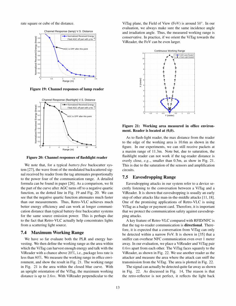
rate square or cube of the distance.
0 0.5 1 1.5 2 2.50
0.1
0.2
0.3
0.4
0.5
0.6
0.7
0.8
0.9
1
Range (m)
Nor
mal
ized
Rec
eive
d E
nerg
y (li
near
)
Channel Response (lamp) V.S. Distance
Normalized Received Energy
Fited AGC off part with y=kx−4
AGC is OFF after this point
Figure 19: Channel responses of lamp reader
0 2 4 6 8 10 120
0.1
0.2
0.3
0.4
0.5
0.6
0.7
0.8
0.9
1
Range (m)
Nor
mal
ized
Rec
eive
d E
nerg
y (li
near
)
Channel Response (flashlight) V.S. Distance
Normalized Received Energy
Fited AGC off part with y=kx−4
AGC is OFF after this point
Figure 20: Channel responses of flashlight reader
We note that, for a typical battery-free backscatter sys-tem [27], the wave front of the modulated backscattered sig-nal received by reader from the tag attenuates proportionallyto the power four of the communication range. A detailedformula can be found in paper [26]. As a comparison, we fitthe part of the curve after AGC turns off to a negative quarticfunction, as the dotted line in Fig. 19 and Fig. 20. We cansee that the negative quartic function attenuates much fasterthan our measurements. Thus, Retro-VLC achieves muchbetter energy efficiency and can work at longer communi-cation distance than typical battery-free backscatter systemsfor the same source emission power. This is perhaps dueto the fact that Retro-VLC actually help concentrates lightsfrom a scattering light source.
7.4 Maximum Working RangeWe have so far evaluate both the PLR and energy har-
vesting. We then define the working range as the area withinwhich the ViTag can harvest enough energy and talk with theViReader with a chance above 20%, i.e., package loss rate isless than 80%. We measure the working range in office envi-ronment, and show the result in Fig. 21. The working rangein Fig. 21 is the area within the closed blue curve. Withan upright orientation of the ViTag, the maximum workingdistance is up to 2.6m. With ViReader perpendicular to the
ViTag plane, the Field of View (FoV) is around 50◦. In ourevaluation, we always make sure the same incidence angleand irradiation angle. Thus, the measured working range isconservative. In practice, if we orient the ViTag towards theViReader, the FoV can be even larger.
−2 −1.5 −1 −0.5 0 0.5 1 1.5 20
1
2
3
4
5
6
7
8
9
10
11
Y (meter)
X (
met
er)
Continuous Working Range
LED Lamp ReaderFlash Light Reader
Figure 21: Working area measured in office environ-ment. Reader is located at (0,0).
As to flash-light reader, the max distance from the readerto the edge of the working area is 10.6m as shown in thefigure. In our experiments, we can still receive packets ata maxim range of 11.3m. Note but, due to saturation, theflashlight reader can not work if the tag-reader distance isoverly close, e.g.., smaller than 0.5m, as show in Fig. 21.This is due to the saturation of the sensors and amplificationcircuits.
7.5 Eavesdropping RangeEavesdropping attacks in our system refer to a device se-
cretly listening to the conversation between a ViTag and aViReader. It is shown that eavesdropping is usually an earlystep of other attacks like man-in-the-middle attacks [11,18].One of the promising applications of Retro-VLC is usingViTag as a badge or payment card. Therefore, it is importantthat we protect the communication safety against eavesdrop-ping attacks.
A key feature of Retro-VLC compared with RFID/NFC isthat the tag-to-reader communication is directional. There-fore, it is expected that a conversation from ViTag can onlybe detected within a narrow FoV. It is shown in [35] that asniffer can overhear NFC communication even over 1 meteraway. In our evaluation, we place a ViReader and ViTag pair0.6m apart from each other. The ViTag faces squarely to theViReader, as shown in Fig. 22. We use another reader as theattacker and measure the area where the attack can sniff thetransmission from the ViTag. The area is plotted in Fig. 22.
The signal can actually be detected quite far away as shownin Fig. 22. As discussed in Fig. 14, The reason is thatthe retro-reflector is not perfect, it reflects the light back
13

−1 −0.5 0 0.5 1−2
−1.5
−1
−0.5
0
0.5
Y (meter)
X (
met
er)
Uplink Transimission Detectable Area
ViTag
ViReader
Figure 22: Signal detection radius of uplink.
with a small diffusion angle. The intensity of light decaysquickly with the angle. In our experiment, we use a snifferthat have 100dBm gain(the same as our ViReader), and theresult shows the detectable area is nearly 2m in the back,excluding the shadow of the ViReader. However, the wholearea resides within a small FoV of the ViTag, making it mucheasier for the user to discern the sniffer and can be blockedby a larger cover of ViReader. Usually, the reader is fixedon the wall (e.g., a badge reader) which further reduces thesignal-detectable area.
8. DISCUSSIONS
Full Duplex vs Half Duplex: Unlike radio backscatteringsystems where achieving full duplex is extremely challeng-ing due to shared antenna and RF front-end, full duplexingis natural to Retro-VLC. This attributes to the fact that sep-arate components are responsible for emitting (LED/retro-reflector) and receiving (photodiode) light. The only differ-ence is that, in full duplexing, the reflected light containsdownlink signals whereas in half duplexing, the reflectedlight is the pure carrier. The different reflected carriers haveno impact on the decoding of uplink, due to LPF at the readerfrontend. Full duplexing also incurs extra power consump-tion as both the receiving and transmitting logics are activeand the MCU will be kept at a high working frequency.
Size Tradeoff: In the ViTag implementation, we dedicatetwo-thirds of the area to solar cell and one-third to retro-reflector. The primary reason is that we have only access tothat sized LCD (obtained from 3D glasses) and the availabil-ity of solar cells. For a target environment (mainly concern-ing the illumination condition) and LED power, we expectan optimal ratio between the area of the solar cell to thatof retro-reflector so as to achieve maximum communicationrange. This is of interest when making real products.
Working with infrared: Since the retro-reflector, the LCD,
the receiving module on the tag and the receiving module onthe LED side can all work on the infrared band, the overallsystem can be used even under a totally dark condition, aslong as the transmitting module is replaced with an infraredtransmitter. This property can be beneficial in scenarios suchas reading with a mobile device in the evening without both-ering others’ sleep, and controlling home appliances withoutturning on the light.
9. CONCLUSIONIn this paper, we have presented a bi-directional VLC sys-
tem called Retro-VLC that consists of a modified LED anda tag device. The tag can run battery-free by harvestinglight energy with solar cells. The ViTag transmits by reflect-ing and modulating incoming light back to the LED usinga retro-reflector and an LCD modulator. The system over-comes the power consumption challenge on the ViTag andinterferences and clock offsets on the LED end, achieving10kbps downlink rate and 0.5kbps uplink rate over a dis-tance up to 2.4m. The system also shows security advan-tages, preventing readers nearby from overhearing uplinkdata. We believe Retro-VLC have wide application scenar-ios.
AppendixProof of Lemma 5.1 Assume the first estimated preamblebit is at t0, and its actual time t0. Denote s[n] as the centraltime of a three bit sequence on ViReader-Rx, and t[n] asthe central time of a three bit sequence on ViTag-Tx, wheret[n+1]−t[n] is the time period of one bit (n : 0, 1, ...,+∞).We have
t[n] = t0 + k · s[n]
where k · s[n] is a mapping from the ViReader-Rx to theactual bit boundaries, which we suppose is linear on thesmall bit-period time scale. The problem is then, given t0, sand t[i], estimate the next actual bit boundary t[i + 1]. Ourmethod is to approach the above equation by drawing a linethat connects (s[i], t[i]) and (0, t0) as the following
t[i+ 1] = t0 +t[i]− t0s[i]
s[i+ 1]
Therefore
errortime = limi→∞
t[i+ 1]− t[i+ 1]
= limi→∞
t0 +(t0 + k · s[i])− t0
s[i]s[i+ 1]
− (t0 + k · s[i+ 1])
= limi→∞
(t0 − t0)(1−s[i+ 1]
s[i]) = 0
The result highlights that the deviation of the bit boundaryestimate will not propagate, and will converge to zero forinfinitely long packets.
14
10. REFERENCES[1] 3M Retro-reflector.
http://qxwujoey.tripod.com/lcd.htm.[2] ByteLight. http://www.bytelight.com/.[3] Modulating Retro-reflector. http://en.wikipedia.org/wik
i/Modulating_retro-reflector.[4] Retro-reflector Principle.
http://en.wikipedia.org/wiki/Retroreflector.[5] D. Bharadia and S. Katti. Full duplex mimo radios. Self, 1(A2):A3,
2014.[6] M. Born and E. Wolf. Principles of optics: electromagnetic theory of
propagation, interference and diffraction of light. CUP Archive,1999.
[7] T. K. Chan and J. E. Ford. Retroreflecting optical modulator using anmems deformable micromirror array. Journal of lightwavetechnology, 2006.
[8] J. I. Choi, M. Jain, K. Srinivasan, P. Levis, and S. Katti. Achievingsingle channel, full duplex wireless communication. In MobiCom’10.
[9] C. Chow, C. Yeh, Y. Liu, and Y. Liu. Improved modulation speed ofled visible light communication system integrated to main electricitynetwork. Electronics letters, 2011.
[10] K. Cui, G. Chen, Z. Xu, and R. D. Roberts. Line-of-sight visible lightcommunication system design and demonstration. In CSNDSP’10,2010.
[11] A. Czeskis, K. Koscher, J. R. Smith, and T. Kohno. Rfids and secrethandshakes: Defending against ghost-and-leech attacks andunauthorized reads with context-aware communications. In CCS’08.
[12] M. Duarte and A. Sabharwal. Full-duplex wireless communicationsusing off-the-shelf radios: Feasibility and first results. InASILOMAR’10.
[13] D. Giustiniano, N. O. Tippenhauer, and S. Mangold. Low-complexityvisible light networking with led-to-led communication. In WirelessDays, 2012 IFIP, 2012.
[14] P. Hu, P. Zhang, and D. Ganesan. Leveraging interleaved signal edgesfor concurrent backscatter. 2014.
[15] S. Jeon, Y. Yu, and J. Choi. Dual-band slot-coupled dipole antennafor 900 mhz and 2.45 ghz rfid tag application. Electronics letters,2006.
[16] B. Kellogg, A. Parks, S. Gollakota, J. R. Smith, and D. Wetherall.Wi-fi backscatter: internet connectivity for rf-powered devices. InSIGCOMM’14.
[17] T. Komine and M. Nakagawa. Integrated system of white ledvisible-light communication and power-line communication.Consumer Electronics, IEEE Transactions on, 2003.
[18] K. Koscher, A. Juels, V. Brajkovic, and T. Kohno. Epc rfid tagsecurity weaknesses and defenses: passport cards, enhanced driverslicenses, and beyond. In CCS’09.
[19] Y.-S. Kuo, P. Pannuto, K.-J. Hsiao, and P. Dutta. Luxapose: Indoorpositioning with mobile phones and visible light. MobiCom’14.
[20] H. Le Minh, D. O’Brien, G. Faulkner, L. Zeng, K. Lee, D. Jung,Y. Oh, and E. T. Won. 100-mb/s nrz visible light communicationsusing a postequalized white led. Photonics Technology Letters, IEEE,2009.
[21] H. Li, Y. Liu, T. Xing, Y. Wang, J. Uribe, H. Baghaei, S. Xie, S. Kim,R. Ramirez, and W.-H. Wong. An instantaneous photomultiplier gaincalibration method for pet or gamma camera detectors using an lednetwork. In Nuclear Science Symposium Conference Record. IEEE,2003.
[22] L. Li, P. Hu, C. Peng, G. Shen, and F. Zhao. Epsilon: a visible lightbased positioning system. In NSDI’14.
[23] V. Liu, A. Parks, V. Talla, S. Gollakota, D. Wetherall, and J. R.Smith. Ambient backscatter: wireless communication out of thin air.In SIGCOMM’13.
[24] D. N. Mansell, P. S. Durkin, G. N. Whitfield, and D. W. Morley.Modulated-retroreflector based optical identification system, 2002.US Patent 6,493,123.
[25] R. Nandakumar, K. K. Chintalapudi, V. Padmanabhan, andR. Venkatesan. Dhwani: secure peer-to-peer acoustic nfc. InSIGCOMM’13.
[26] P. V. Nikitin and K. S. Rao. Theory and measurement ofbackscattering from rfid tags. Antennas and Propagation Magazine,IEEE, 48(6):212–218, 2006.
[27] A. N. Parks, A. Liu, S. Gollakota, and J. R. Smith. Turbochargingambient backscatter communication. In SIGCOMM’14.
[28] W. S. Rabinovich, G. C. Gilbreath, P. G. Goetz, R. Mahon, D. S.Katzer, K. Ikossi-Anastasiou, S. C. Binari, T. J. Meehan, M. Ferraro,I. Sokolsky, et al. Ingaas multiple quantum well modulatingretro-reflector for free-space optical communications. InInternational Symposium on Optical Science and Technology.International Society for Optics and Photonics, 2002.
[29] W. S. Rabinovich, R. Mahon, P. Goetz, E. Waluschka, D. Katzer,S. Binari, and G. Gilbreath. A cat’s eye multiple quantum wellmodulating retro-reflector. Technical report, DTIC Document, 2006.
[30] N. Rajagopal, P. Lazik, and A. Rowe. Visual light landmarks formobile devices. In IPSN’14.
[31] S. Schmid, G. Corbellini, S. Mangold, and T. R. Gross. Led-to-ledvisible light communication networks. In MobiHoc’13.
[32] L. Ukkonen, M. Schaffrath, D. W. Engels, L. Sydanheimo, andM. Kivikoski. Operability of folded microstrip patch-type tagantenna in the uhf rfid bands within 865-928 mhz. Antennas andWireless Propagation Letters, IEEE, 2006.
[33] J. Vucic, C. Kottke, S. Nerreter, K.-D. Langer, and J. W. Walewski.513 mbit/s visible light communications link based ondmt-modulation of a white led. Journal of Lightwave Technology,2010.
[34] Q. Wang, D. Giustiniano, and D. Puccinelli. Openvlc:software-defined visible light embedded networks. In VLCS’14.
[35] R. Zhou and G. Xing. nshield: a noninvasive nfc security system formobiledevices. In MobiSys’14.
15
Related Documents