Aalborg Universitet Response of Rubble Foundation to Dynamic Loading Burcharth, H. F.; Ibsen, Lars Bo Published in: Proceedings of Workshop MAST 2 Project CT92-0047 on Monolithic Coastal Structures Publication date: 1993 Document Version Early version, also known as pre-print Link to publication from Aalborg University Citation for published version (APA): Burcharth, H. F., & Ibsen, L. B. (1993). Response of Rubble Foundation to Dynamic Loading. In Proceedings of Workshop MAST 2 Project CT92-0047 on Monolithic Coastal Structures : Madrid, October 1993 General rights Copyright and moral rights for the publications made accessible in the public portal are retained by the authors and/or other copyright owners and it is a condition of accessing publications that users recognise and abide by the legal requirements associated with these rights. ? Users may download and print one copy of any publication from the public portal for the purpose of private study or research. ? You may not further distribute the material or use it for any profit-making activity or commercial gain ? You may freely distribute the URL identifying the publication in the public portal ? Take down policy If you believe that this document breaches copyright please contact us at [email protected] providing details, and we will remove access to the work immediately and investigate your claim. Downloaded from vbn.aau.dk on: October 08, 2021

Welcome message from author
This document is posted to help you gain knowledge. Please leave a comment to let me know what you think about it! Share it to your friends and learn new things together.
Transcript

Aalborg Universitet
Response of Rubble Foundation to Dynamic Loading
Burcharth, H. F.; Ibsen, Lars Bo
Published in:Proceedings of Workshop MAST 2 Project CT92-0047 on Monolithic Coastal Structures
Publication date:1993
Document VersionEarly version, also known as pre-print
Link to publication from Aalborg University
Citation for published version (APA):Burcharth, H. F., & Ibsen, L. B. (1993). Response of Rubble Foundation to Dynamic Loading. In Proceedings ofWorkshop MAST 2 Project CT92-0047 on Monolithic Coastal Structures : Madrid, October 1993
General rightsCopyright and moral rights for the publications made accessible in the public portal are retained by the authors and/or other copyright ownersand it is a condition of accessing publications that users recognise and abide by the legal requirements associated with these rights.
? Users may download and print one copy of any publication from the public portal for the purpose of private study or research. ? You may not further distribute the material or use it for any profit-making activity or commercial gain ? You may freely distribute the URL identifying the publication in the public portal ?
Take down policyIf you believe that this document breaches copyright please contact us at [email protected] providing details, and we will remove access tothe work immediately and investigate your claim.
Downloaded from vbn.aau.dk on: October 08, 2021
Pubiiihed at "First Project Workshopn, Madrid, October 13-14-1993, MAST 2/MCS Project. Monolithic (Vertical) Coastal Structures. Subtask 1.1
RESPONSE OF RUBBLE FOUNDATION TO DYNAMIC LOADING
H.F. Burcharth a n d Lars Bo Ibsen
Aalborg University, Denmark
1. I N T R O D U C T I O N The soil beneath vertical monolithic structures is subjected to a combi- nation of static load due to the submerged weight of the structure and stochastic non-stationary loads as a result of the wave loads on the vertical wall. The stress conditions in the soil below a foundation exposed to both static and stochastic varying loadings (horizontal, vertical and moment) are very complex.
Figure 1 shows an attempt to describe this complexity outlining a sim- plified picture of the shear stress in representative elements. -
The figure shows that wave loads on vertical wali structures show a ir- regular non-stationary signal. This force signal is transformed to a more regular stress variation in the soil due to the dampening and dynamic am- plifications of the structures/soil. The stress variation is, on the other hand, stili irregular and non-periodic. The stress development varies from one ele- ment to the other depending on the ratio of the static and the varying stress components. The structure/soil response is best handled in a time-domain analysis, e.g. a ful1 dynamic approach based on finite-element methods (FEM). Due to the complexity of the problem and the present stage of the FEM it is not possible to perform such an analysis. No constitutive models exist which describe the true development of stress, strain and pore pressures in the soil beneath structures subjected to irregular loading.

- F Time
Time Ti Time
Time Ti Time - Figure 1. Sim~lified stress conditions for some elements in the soil below a vertical monolithic structure exposed to 60th static and stochastic non- stationary loads.
As a consequence a more simple approach for the estimation of the soil response will be sought developed.
The basis of the method is the fact that the intrinsic soil pararneters nec- essary for the description of the development of stress, strain and pore pres- sure can be determined in triaxial tests where cyclic loadings are applied. Thus, the response of a soil sample to "cyclic loadings" can be determined when the initial conditions are known.
If the real wave induced loadings, which are of stochastic (irregular) nature, can be replaced by LLequivalent cyclic loadings", i.e. loads which produce equivalent stress-strain-pore pressures in the soil, an estimation of the soil response under wave induced loadings can be given.
The present research in limited to coarse, non-whesive soils, i.e. coarse sand, grave1 and quarry rock.
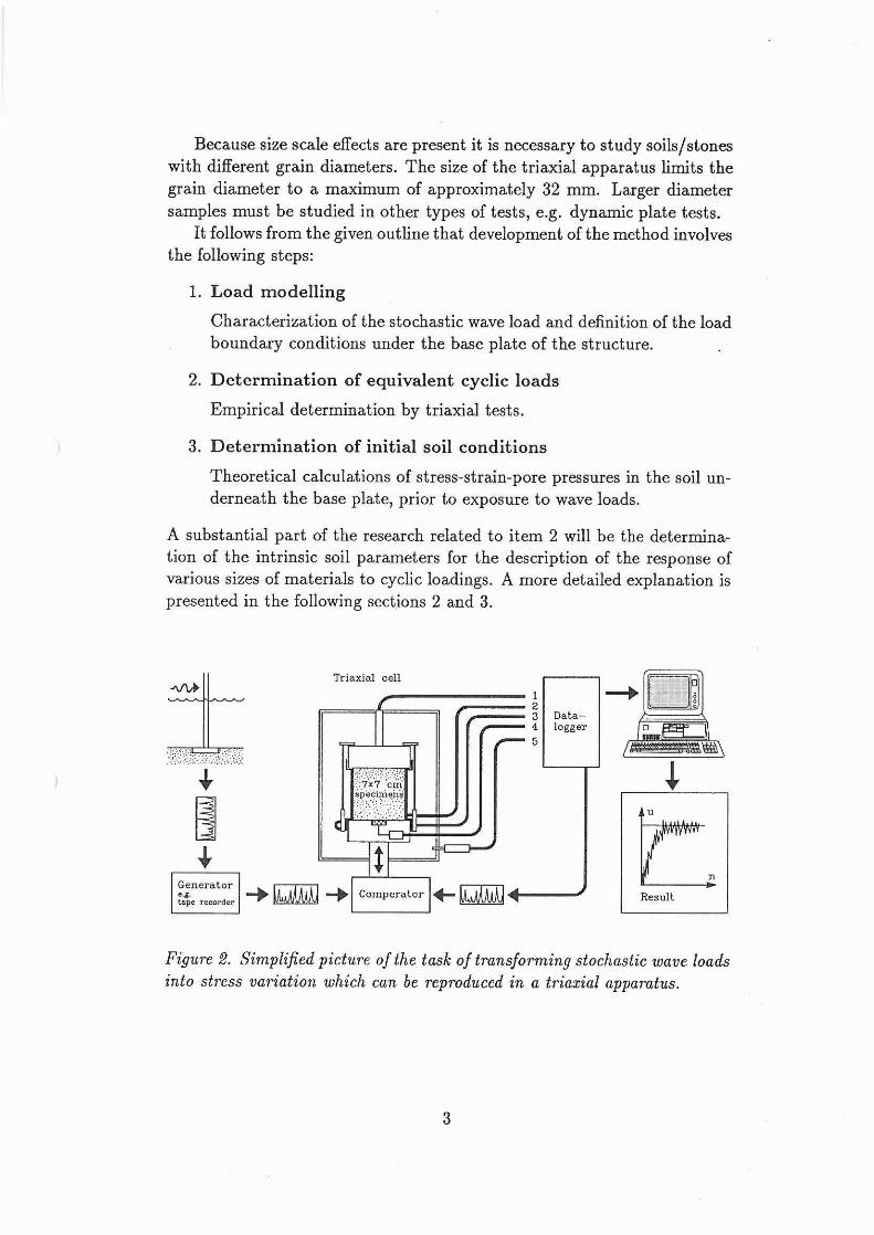
Because size scale effects are present it is necessary to study soils/stones with different grain diameters. The size of the triaxial apparatus limits the grain diameter to a maximum of approximately 32 mm. Larger diameter samples must be studied in other types of tests, e.g. dynamic plate tests.
It follows from the given outline that development of the method involves the following steps:
1. Load modelling
Characterization of the stochastic wave load and definition of the load boundary conditions under the base plate of the structure.
2. Determinat ion of equivalent cyclic loads
Empirical determination by triaxial tests.
3. Determinat ion of initial soil conditions
Theoretical calculations of stress-strain-pore pressures in the soil un- derneath the base plate, prior to exposure to wave loads.
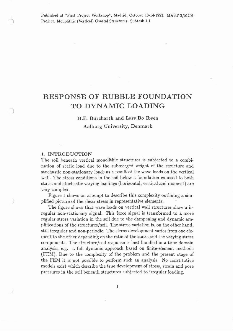
A substantial part of the research related to item 2 will be the determina- tion of the intrinsic soil parameters for the description of the response of various sizes of materials to cyclic loadings. A more detailed explanation is presented in the following sections 2 and 3.
Figure 2. Simplified picture of the task of transforming stochastic wave loads into stress variation which can be reproduced in a triaxial apparatus.

2. LOAD MODELLING Wave loads on vertical wali structures show a stochastic non-stationary behaviour. The related structural/soil mechanic response is best handled in time-domain analyses. Due to the complexity and the present stage of such analyses a simplified approach involving transformation of the stochastic load into cyclic load will be explored as a first step. Thus, all time series describing the boundary conditions for the soil mechanic calculations must be transformed from the real non-stationary irregular signals to a sequence of stationary regular periodic signals causing equivalent effects in t e r m of pore pressures, effective stresses and deformations.
2.1 Overall approach The research for such "equivalent signals" must be performed in two steps:
Step 1 . The stationay case Transformation of a stationary irregular signal into an equivalent periodic signal.
Figure 3. The figure signifies the situation in stationay periods dun'ng a storm, say a 2 hour duration peak of a storm.
Step 2. The non-stationay case Transformation of a sequence of different periodic signals into one equivalent periodic signal.
Figure 4. The figure signifies conditions under a s tom.
Determination of the composition of equivalent signals will be based on dynamic triaxial testing of samples including experience kom existing test results.
The input signal is chosen to be a load history signifying the stress boundary conditions under the heel of a caisson which is exposed to irregular waves.

2.2 Definition of load history ad. Step 1 The wave surface amplitude signal analyzed with respect to wave heights follows a Rayleigh distribution closely if no wave breaking due to limited water depth takes place.
If depth limited conditions are present the wave heights follow a trun- cated Rayleigh distribution.
The wave loads in terms of the resultant of the wave induced horizontal force on a non-overtopped vertical wall exposed to irregular non-breaking . waves can be described by a Rayleigh distribution due to proportionality ' between wave amplitude and wave force if, for simplicity, linear wave theory is applied.
In case of wave breaking on the wall and/or overtopping of the wall the wave force amplitude signal does not follow a Rayleigh distribution but some other distributions which in general are unknown.
Bowever, even though the distribution of the resultant wave force am- plitude is known, the force exerted on the soil a t a specific point of the caisson bottom slab will not follow the same distribution: This is because the position of the resultant wave force on the wall changes with the wave amplitude. Moreover, in case of high-frequency wave loading from breaking waves also dampening and dynamic amplifications can transform the signal.
In the present study it is proposed to apply either Rayleigh distributed force amplitude signals or/and force amplitude signals recorded from the caisson model tests a t FI.
In order to generalize the results, the force amplitude signals must be described by characteristic parameters as follows, cf. the figure:
t Force, F
Figure 5.
Force 'Lheights" HF are defined by the down-crossings using the mean force value, F, as the crossing line.
The force "periods", TF = 5, are defined from the down-crossings.
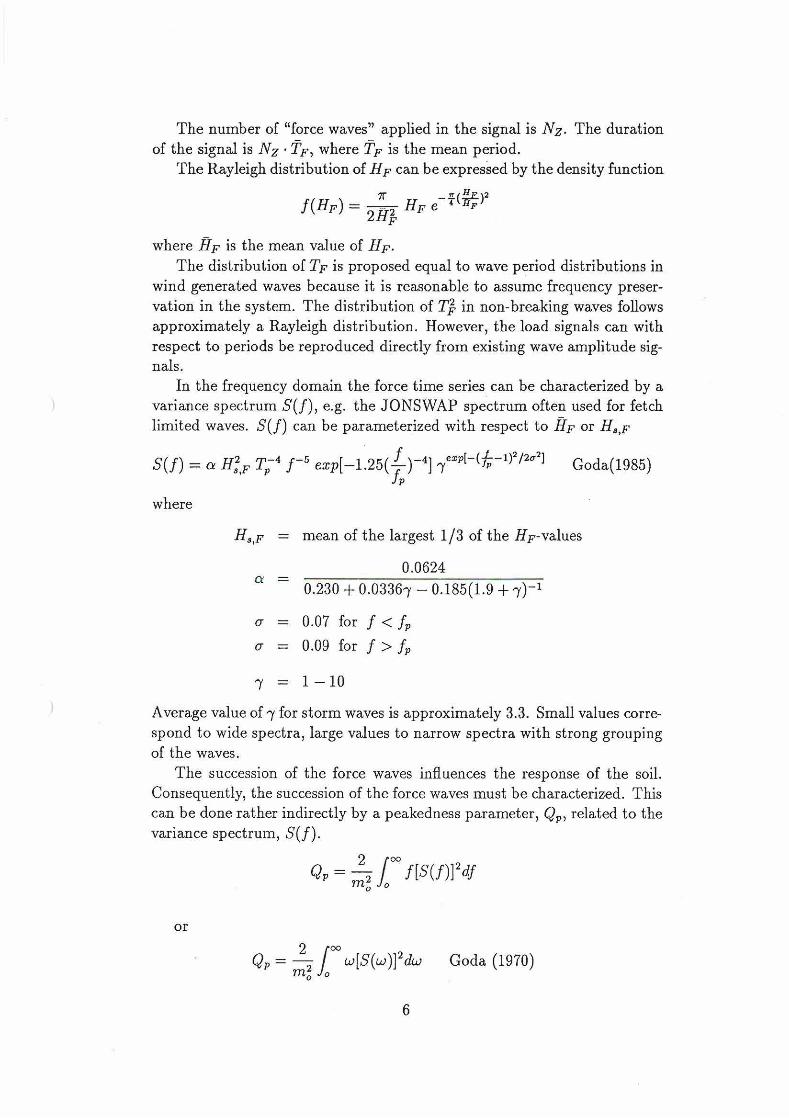
The number of "force waves" applied in the signal is Nz. The duration of the signal is N z . TF, where TF is the mean period.
The Rayleigh distribution of HF c m be expressed by the density function
where HF is the mean value of HF. The distribution of TF is proposed equal to wave period distributions in
wind generated waves because it is reasonable to assume frequency preser- vation in the system. The distribution of T$ in non-breaking waves foiiows approximately a Rayleigh distribution. However, the load signals can with respect to periods be reproduced directly from existing wave amplitude sig- nals.
In the frequency domain the force time series can be characterized by a variance spectrum S(f), e.g. the JONSWAP spectrum often used for fetch limited waves. S(f) c m be parameterized with respect to HF or HS,p
where
Ha,F = mean of the largest 113 of the HF-values
u = 0.07 for f < f, u = 0.09 for f > f,
Average value of y for storm waves is approximately 3.3. Smal1 values corre- spond to wide spectra, large values to narrow spectra with strong grouping of the waves.
The succession of the force waves influences the response of the soil. Consequently, the succession of the force waves must be characterized. This can be done rather indirectly by a peakedness parameter, Q,, related to the variance spectrum, S(f).
where w = 9. The groupiness parameter, GFt, can also be used.
where TR is record length, E, is the smoothed instantaneous wave energy history (SIWEH, Funke and Mansard, 1979) and E, = m, is the zero spec- tral moment.
In summary the force time series can be identified by the following set of parameters if we presume Rayleigh distributed force amplitudes:
F, HF, TF, N, (time domaine)
F, Ha,,vi S(f), N=, Q, (frequency domaine)
The applied range of TF corresponds to the range of wave periods in nature. For N, a relevant range is 500 - 2000 corresponding to stationary wave
load situations. With respect to groupiness two variations should be investigated corre-
sponding to a narrow spectrum (strongly grouped force wave heights) and a wide spectrum (randomly distributed force wave heights), i.e. Q, = 6 and 1, respectively and approximately corresponding to -f = 10 and 1, respectively.
The relevant range of F and H must be determined by calculation of relevant prototype situations.
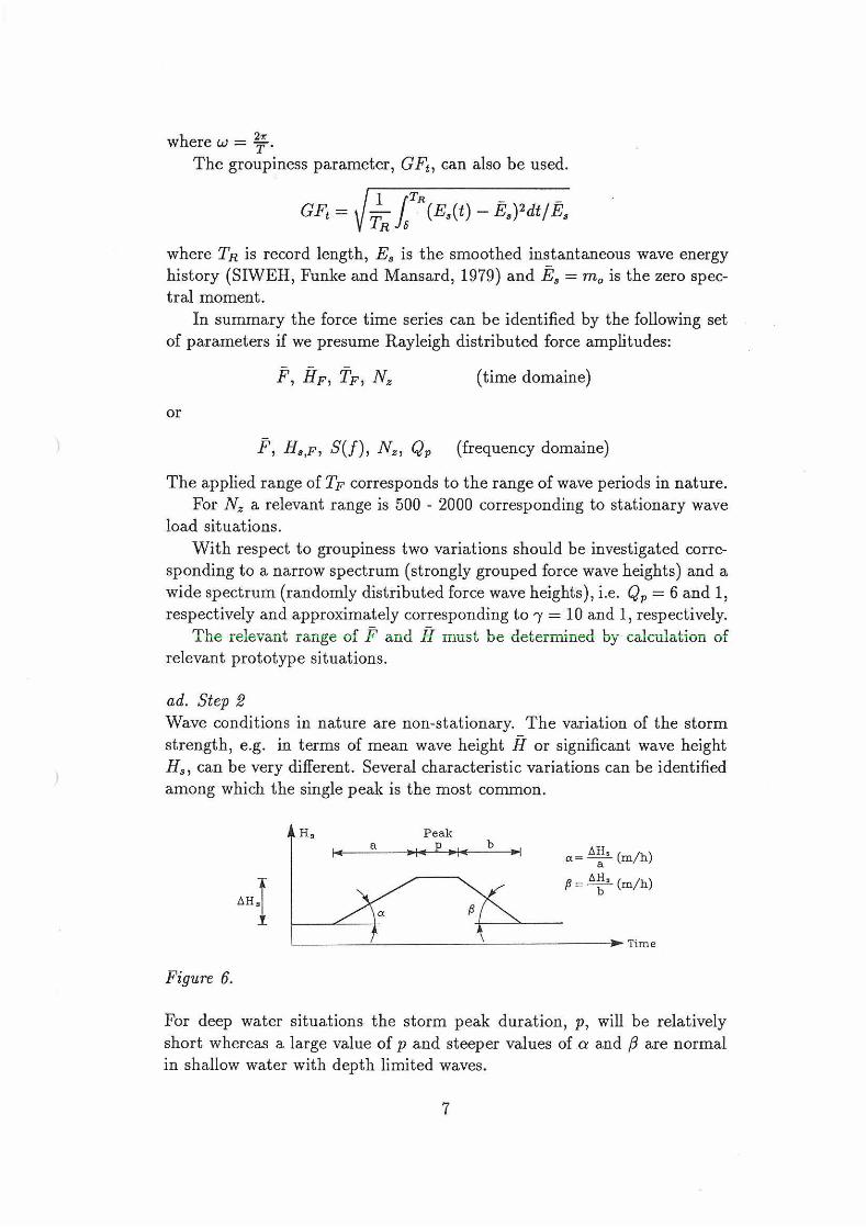
ad. Step 2 Wave conditions in nature are non-stationary. The variation of the storm strength, e.g. in terms of mean wave height H or significant wave height H,, can be very different. Several characteristic variations can be identified among which the single peak is the most common.
Peak a AH a = 2 (m/h)
a
Time
For deep water situations the storm peak duration, p, wiii be relatively short whereas a large value of p and steeper values of a and ,9 are normal in shallow water with depth limited waves.
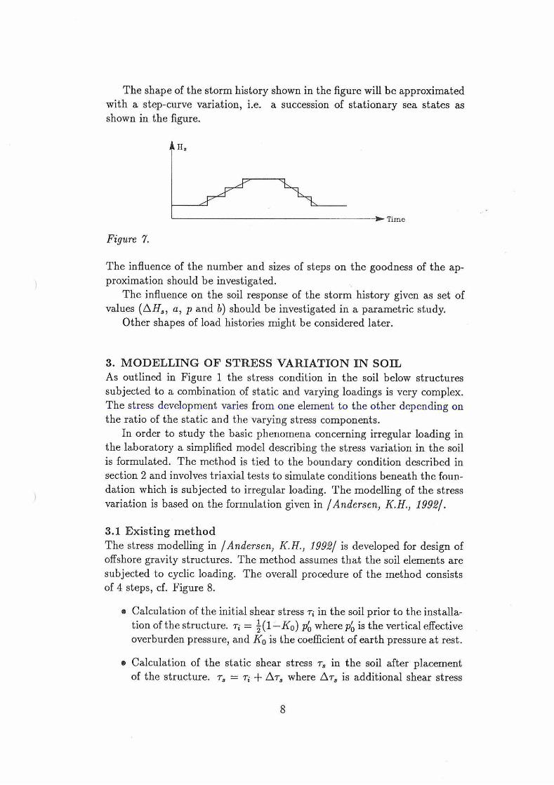
The shape of the storm history shown in the figure wiii be approximated with a step-curve variation, i.e. a succession of stationary sea states as shown in the figure.
Time
The influence of the number and sizes of steps on the goodness of the ap- proximation should be investigated.
The influence on the soil response of the storm history given as set of values (AH,, a, p and b) should be investigated in a parametric study.
Other shapes of load histories rnight be considered later.
3. MODELLING OF STRESS VARIATION IN SOIL As outlined in Figure 1 the stress condition in the soil below structures subjected to a combination of static and varying loadings is very complex. The stress development varies from one element to the other depending on the ratio of the static and the varying stress components.
In order to study the basic phenomena concerning irregular loading in the laboratory a simplified model describing the stress variation in the soil is formulated. The method is tied to the boundary condition described in section 2 and involves triaxial tests to simulate conditions beneath the foun- dation which is subjected to irregular loading. The modelling of the stress variation is based on the formulation given in /Andersen, K.H., 1992/.
3.1 Existing method The stress modelling in /Andersen, K.H., 1992/ is developed for design of offshore gravity structures. The method assumes that the soil elements are subjected to cyclic loading. The overall procedure of the method consists of 4 steps, cf. Figure 8.
Calculation of the initial shear stress ri in the soil prior to the installa- tion of the structure. ri = i(1-KO) p; wherepó is the vertical effective overburden pressure, and Ko is the coefficient of earth pressure at rest.
Calculation of the static shear stress T, in the soil after placement of the structure. T, = ri + Ar8 where AT, is additional shear stress
induced by the submerged weight of the platform.
Calculation of the cyclic shear stress T,, caused by the cyclic loading. The cyclic shear stress is calculated with consideration to possible dynarnic amplification.
Estimation of stress and strain development under cyclic loading based on results from triaxial and direct simple shear tests.
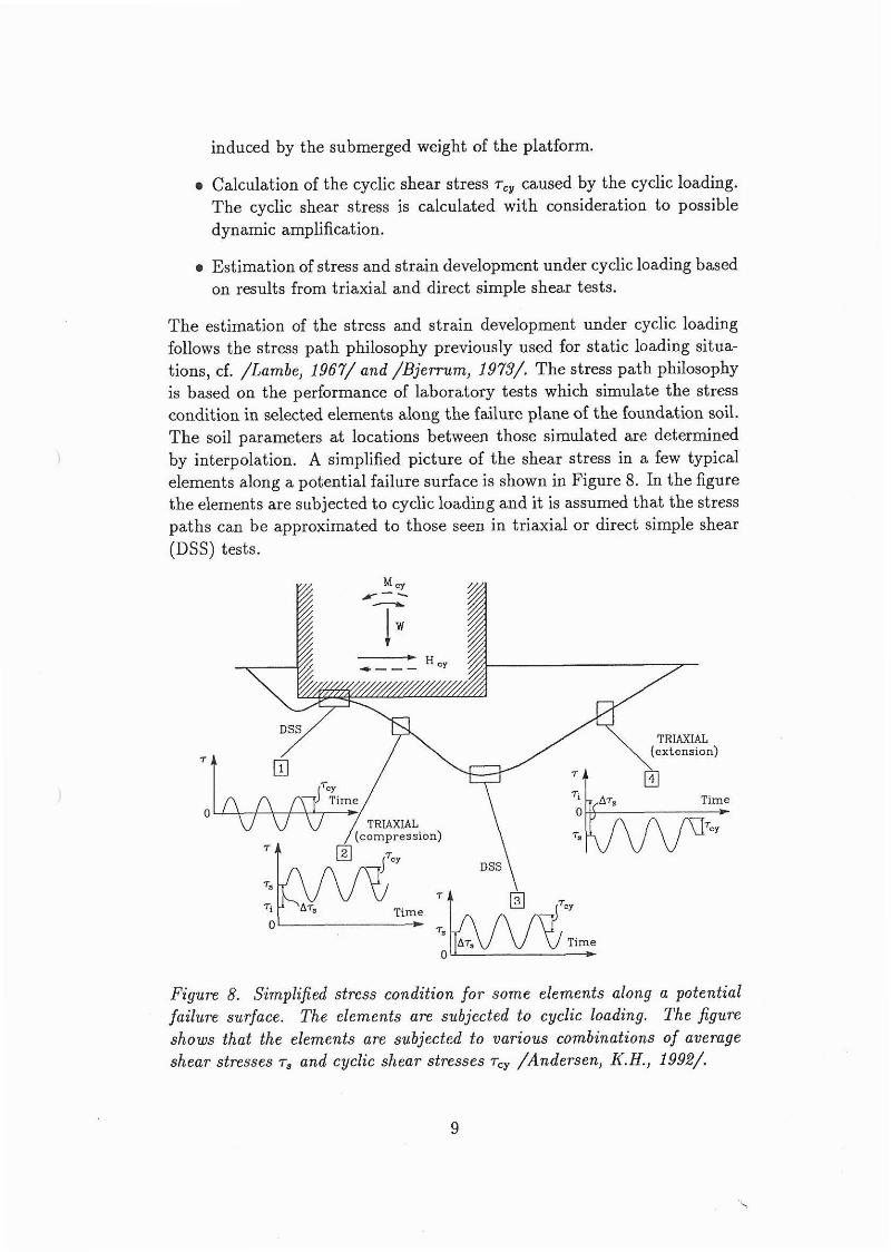
The estimation of the stress and strain development under cyclic loading follows the stress path philosophy previously used for static loading situa- tions, cf. /Lambe, 1967/ and /Bjerrum, 1973/. The stress path philosophy is based on the performance of laboratory tests which simulate the stress condition in selected elements along the failure plane of the foundation soil. The soil parameters at locations between those simulated are determined by interpolation. A simplified picture of the shear stress in a few typical elements along a potential failure surface is shown in Figure 8. In the figure the elements are subjected to cyclic loading and it is assumed that the stress paths can be approximated to those seen in triaxial or direct simple shear (DSS) tests.
Time
\
Ti
A& Time Time o I, - mcy Figure 8. Simplified stress condition for some elements along a potential failure surface. The elements are subjected to cyclic loading. The figure shows that the elements are subjected to various combinations of average shear stresses T, and cyclic shear stresses T,, /Andersen, K.H., 1992/.

3.2 New method The modelling of the stress variation is similar to the formulation given in /Andersen, K.H. 1992/, but the cdculation of the stress variation is performed differently. Instead of using the stress path philosophy, it is proposed to use a FEM model to calculate the stress variation in the soil space. This gives the advantage that the stress variation can be described in every element of the soil space and not only in some elements along a potential failure surface.
In order to perform laboratory tests which simulate the condition in the soil, some approximations must be introduced. Compared to e.g. triaxial tests, the stress condition below a foundation exposed to irregular loading is - apart from being three-dimensional - complicated, because the principle stress direction rotates continuously. For laboratory testing /Andersen, K.H., 1992/simplified the stress condition by determining the shear stress T on fixed planes. In triaxial tests the shear stress variation is determined on a 45" plane. For the direct simple shear test, the shear stress is determined on a horizontal plane, see Figure 8.
As a result of the finite-element methods used at Aalborg University it is chosen to describe the actual stress condition and stress variation below the foundation using the invariants:
Compared to triaxial loadings, the advantage of expressing the stress vari- ation in the soil by stress invariants is that they are independent of the rotation of the principle stresses. Assuming that the changes in the in- variant~ alone govern the changes in pore pressure, the shear stress can be described as:
since u: 2 u; 2 04. The mean stress condition can be described as:
By varying o: in the triaxial tests, the same variation of T as in the soil element can be reproduced, since

3.3 Determination of static and cyclic stress variation Figure 9 shows an attempt to describe a simplified picture of the variation of the shear stress, T, in representative elements subjected to cyclic load- ing. The figure is identical to Figure l except that the stochastic loads are replaced by cyclic loads.
Ti r, Time Time Ti Time
* Cyclic Liquefaction Mobilisering Stabilization Necking
T, Time Time
Cyclic Liquefaction Instant Stabilization
Figure 9. Simplijied picture of the stress condition beneath a foundation submitted to both static and cyclic loading.
Stat ic shear stress In Figure 9 T denotes the shear stress determined as
and
e T; is the initial shear stress in the soil prior to the installation of the structure.

The initial shear stress is assumed to act under drained condition and the soil is assumed fully consolidated under this stress.
AT, is the change in the average shear stress due to the submerged weight of the structure.
Depending on the type of soil AT, will initially act under undrained condi- tions but as the soil consolidates this shear stress will also act under drained conditions.
In the case of a rubble mound foundation the consolidation will be in- stant. In the case of a sand foundation drainage will occur relatively rapidly and it is reasonable to assume that the soil wnsolidates before the design storm arrives. The effective static shear stress to which the soil element is subrnitted before the variation load is added can be expressed as
Cyclic shear stress The stress development varies from one soil element to the other and de- pends on the combinations of average shear stresses of the cycle, T,, and cyclic shear stress, T,,, cf. Figure 9. Due to the symmetry of the loading T, is constant and identical to the static shear stress, T,, which is induced by the submerged weight of the structure. The number of cycles N for the duration t of the signal is
where T is the periods of the cycle. The behaviour of sand during cyclic loading has been studied inten-
sively at Aalborg University under different combinations of average and cyclic shear stresses, using the Danish Triaxial Cell. As described in /Ib- sen, L.B., 1993.2/a new characteristic state "The Cyclic Stable Staten has been discovered. The cyclic stable state occurs when the positive and neg- ative pore pressures generated during a loading cycle neutralize each other. The mean normal stress does not change when the stable state has been reached and the cyclic loading will not lead to further hardening or soften- ing of the soil. If cyclic tests are executed at different average stress levels the stable states describe a line in the stress Space ILThe Cyclic Stable Linen, CSL-line, shown in Figure 10. If the average shear stress level is situated below the stable line the cyclic test will try to reach the equilibrium of the stable state. The test will generate positive pore pressures and the phe- nomena "Pore Pressure Buildup" or 'Tyclic Liquefaction" will be observed. If the average stress level is situated above the stable line the cyclic test

will generate negative pore pressures and the phenomena "Stabilization" or "Instant Stabilizationn will be observed.
Figure 10. Illustration of the phenomena a) Cyclic Liquefaction, b) Pore Pressure Buildup, c) Stabilization and d) Instant Stabilization. Sand speci- mens with equal height and diameter exposed to cyclic loading.
The average shear stress, T,, the cyclic shear stress, T,,, and the number of cycles, N, are the parameters needed as input parameters for the cyclic fatigue model described in /Ibsen, L.B., 1993.1/. The output is the re- distribution of the effective stresses expressed by the changes of the pore pressure, Au, due to cyclic loading. By assuming undrained conditions in the soil during the cyclic loading, the cyclic fatigue model can be used to determine the redistribution of the effective stresses at each soil element beneath the foundation. The result of such a calculation is seen in Figure 11.

Figure 11. Redistribution of the effectiue stresses expressed b y the changes of the pore pressure beneath a Gullfaks A platform founded on Lund No O sand. The changes of the pore pressure are specified in kPa and a result of a 3 hour design period.
A sand foundation beneath a typical gravity platform is not likely to remain undrained during a 3 hour storm. It is more likely that part of the generated pore pressures will dissipate which means that the effects of partly draining must be taken into account.
3.3 Determinat ion of irregular stress variation The irregular variation of r in a soil element is characterized by the para- meter shown in Figure 12. The "stress waves" are identified by the zera- down crossings using the average shear stress, r,, as the crossing line.
For each wave a mean stress, ra,i, and a cyclic stress, rcy,i, is defined. Index i stands for the i'th wave. rcY,i is the stress amplitude, i.e. half of the stress wave height. Using the shear stress value, rs, related to the conditions prior to the irregular loading, we define a stress deviation for the i'th wave as
The average shear stress is defined as
The period of the stress wave, z, is defined from the down-crossings.

Figure 12. Definition of parameters describing the irregular stress varia- t i o n ~ .
The experience from existing tests indicate that the same phenomena as observed during cyclic loading exist during irregular loading. If the mean average shear stress level, .T, is situated below the CSL-line, the test will generate positive pore pressure and if it is situated above the stable line, the test will generate negative pore pressure. (Instead of the CSL-line there is some indication that the characteristic line CL controls the generation of pore pressure during irregular loading, see /fisen, L.B., 1993,2/. Further investigations are needed to clarify this point.
Similar to the cyclic loading the parameters which wntrol the generation of pore pressure during irregular loading under undrained conditions are characterized by the mean average shear stress, ;i., and the mean cyclic shear stress, 7,. The rate at which the pore pressure develops is influenced by the distribution of f (T,), f (T,) and f (AT:). Typical distributions might be estimated by step-wise calculations of stresses using real wave load signals and finite element calculations corresponding to fully drained conditions. The influence of the parameters describing the storm history AH,, a, p and b should be investigated during this parametric study.
To be able to transform the real irregular stress variation to a sequence of stationary regular stress cycles causing equivalent effect in terms of pore pressure generation, the effect of different distribution of f (.r,), f (T,,) and f (AT:) must be studied by dynamic triaxial tests.
References Andersen, K.H. (1992). Foundation design of offshore gravity structures. Norwegian Geotechnical Institute Publication 185.
Bjerrum, L. (1973). Geotechnical problems involved in foundations of struc-

tures in the North Sea. Norwegian Geotechnical institute Publication 100.
Goda, Y. (1985). Random Seas and Design of Maritime Structures. Uni- versity of Tokyo Press, 1985.
Ibsen, L.B. (1993.1). Poretryksopbygning i sand. Ph.D. Thesis. Aalborg University.
Ibsen, L.B. (1993.2). The Stable State in Cyclic Loading. Soil Dynarnics & Earthquake Engineering. 6th Int. Conference. Bath, June 1993.
Lambe, T.W. (1967). Stress path method. J. Geotech. Engineering Proc. ASCE 93 (SM6) p. 309-331.
Related Documents