International Journal of Bridge Engineering (IJBE), Vol. 2, No. 2, (2014), pp. 21-30 RESPONSE OF BOX GIRDER BRIDGE SPANS Influence Based Moving Load Analysis G. Venkata Siva Reddy 1 , P. Chandan Kumar 2 1,2 GIT, Gitam University, Dept. Civil Engineering, Visakhapatnam, India email: [email protected], [email protected] ABSTRACT: Recent developments in the field of Bridge engineering, Box Girder Bridges have heightened the need for improving the ability to carry the live load and undertaken as a result of code provisions. This paper deals with the response of Reinforced concrete and Prestressed concrete bridges when subjected to standard moving vehicular loads. Currently length of the span and width of the carriage way are kept constant for the models and analysis is carried out using MIDAS CIVIL software. Influence based moving load analysis: Influence lines and Influence surfaces are generated to analyze the response of bridge structure subjected to live loading within designated lanes. BM, SF and Displacements are obtained by placing moving tracer at different positions of the designed lanes throughout the span length. This study makes an attempt to develop efficient geometric models for new constructions, and to provide necessary structural configuration against live load bending moments, shear force and displacements. The determination of absolute maximum live shear and bending moment due to moving concentrated loads on the box girders is discussed. KEYWORDS: Bridges, Box girders, Bending moments, Displacement, Moving tracer, Shear force. 1 INTRODUCTION Influence based moving load analysis had important application for the design of bridge super-structures that resist large live loads. Influence lines and Influence surfaces are generated to analyse the response of bridge structure subjected to moving vehicle live loading within designated lanes. The theory is applied to the structures subjected to uniformly distributed load, or a series of concentrated forces developed by the vehicle on the span. It was well known that shear and moment diagrams represent the most descriptive methods for displaying the variation of loads in a member. If a structure is subjected to a live

Welcome message from author
This document is posted to help you gain knowledge. Please leave a comment to let me know what you think about it! Share it to your friends and learn new things together.
Transcript
International Journal of Bridge Engineering (IJBE), Vol. 2, No. 2, (2014), pp. 21-30
RESPONSE OF BOX GIRDER BRIDGE SPANS Influence Based Moving Load Analysis
G. Venkata Siva Reddy1, P. Chandan Kumar
2
1,2 GIT, Gitam University, Dept. Civil Engineering, Visakhapatnam, India
email: [email protected], [email protected]
ABSTRACT: Recent developments in the field of Bridge engineering, Box
Girder Bridges have heightened the need for improving the ability to carry the
live load and undertaken as a result of code provisions. This paper deals with
the response of Reinforced concrete and Prestressed concrete bridges when
subjected to standard moving vehicular loads. Currently length of the span and
width of the carriage way are kept constant for the models and analysis is
carried out using MIDAS CIVIL software. Influence based moving load
analysis: Influence lines and Influence surfaces are generated to analyze the
response of bridge structure subjected to live loading within designated lanes.
BM, SF and Displacements are obtained by placing moving tracer at different
positions of the designed lanes throughout the span length. This study makes an
attempt to develop efficient geometric models for new constructions, and to
provide necessary structural configuration against live load bending moments,
shear force and displacements. The determination of absolute maximum live
shear and bending moment due to moving concentrated loads on the box girders
is discussed.
KEYWORDS: Bridges, Box girders, Bending moments, Displacement,
Moving tracer, Shear force.
1 INTRODUCTION Influence based moving load analysis had important application for the design
of bridge super-structures that resist large live loads. Influence lines and
Influence surfaces are generated to analyse the response of bridge structure
subjected to moving vehicle live loading within designated lanes. The theory is
applied to the structures subjected to uniformly distributed load, or a series of
concentrated forces developed by the vehicle on the span. It was well known
that shear and moment diagrams represent the most descriptive methods for
displaying the variation of loads in a member. If a structure is subjected to a live

22 Response of box girder bridge spans – Influence based moving load analysis
load or moving load, the variation of shear and bending moment in the member
is best described using the influence line. An influence line represents the
variation of the reaction, shear, moment or deflection at a specific point in a
member as a concentrated force moves over the member.
In this context, this paper explains how different types of box girder bridge
decks perform under different standard moving load cases. 70 m continuous
span length for RCC & PSC box girders with 12.6 m of top flange width, in
which 9.6 m of effective carriage way designed for two lanes and footpaths of
1.5 m on either side are adopted for the analysis purpose. Moving load cases are
defined as per Indian Roads Congress (IRC: 6-2000) codal provisions i.e., one
lane of 70R loading or two lanes of Class A loading, if the effective width of
carriage way is up to 9.6 m. Out of two load cases Class A loading is the heavy
loading and all the National Highways built in India should design for this
heavy loading. Dimensions of box girders are taken with respect from clause
9.3.2 of IRC: 18-2000. Analysis is carried out at different positions on each key
element to produce live bending moments, shear forces and Displacements. The
design aspects, detailing of reinforcement, sub-structure details like pier cap,
pier and foundation details are excluded from the current study.
2 LITERATURE SURVEY Fushun LIU et al. [1] deals with New Damage-Locating Method for bridges
subjected to a moving load by introducing a new moving load damage-locating
indicator (MLDI). From his study a vehicle is modeled as a moving load and
the damage is simulated by a reduction of stiffness properties of the elements.
His conclusion indicates, the method not only can determine a single damage
location accurately, but also can determine multiple damages in a simply
supported bridge or in a continuous bridge.
C Adam et al. [2] made studies on Reliable Dynamic analysis of an uncertained
composite bridge under traffic loads. According to his studies, the main
structure is modeled as a two-layer beam consisting of a steel girder connected
elastically to the concrete deck. The governing sixth-order partial differential
equation of motion of the homogenized beam is extended to include uncertainty
in the mechanical property of the interface. He concluded that the above
efficient analysis can be performed without reliable knowledge of the
uncertainty of the material parameters by considering structural inherent worst
case scenarios.
G Venkata Siva Reddy, P Chandan Kumar 23
3 NEED FOR THE STUDY The need for the present study is to develop efficient, economical and reliable
box girder super structure bridge spans under moving loads (live loads) with
minimum shear force and bending moments. Two types of box girders are
modeled and evaluated its structural performance with respect to member
strength. The results obtained from MIDAS CIVIL software for two models at
different specified points are correlated with each other and selected an efficient
structural member for further design purpose. Moving tracer, moving load
analysis give accurate live load distribution of the span at a specified points
within the designated lanes.
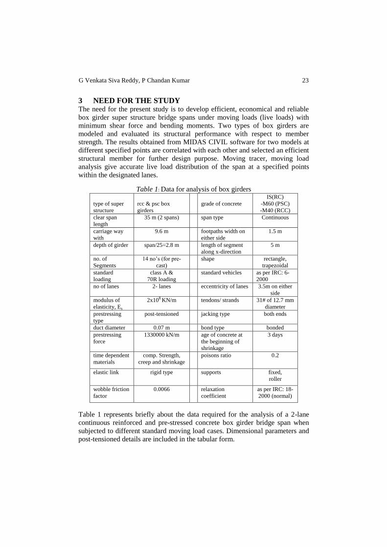
Table 1: Data for analysis of box girders
type of super
structure
rcc & psc box
girders
grade of concrete
IS(RC)
-M60 (PSC)
-M40 (RCC)
clear span
length
35 m (2 spans) span type Continuous
carriage way
with
9.6 m footpaths width on
either side
1.5 m
depth of girder span/25=2.8 m length of segment
along x-direction
5 m
no. of
Segments
14 no’s (for pre-
cast)
shape rectangle,
trapezoidal
standard
loading
class A &
70R loading
standard vehicles as per IRC: 6-
2000
no of lanes 2- lanes eccentricity of lanes 3.5m on either
side
modulus of
elasticity, Es
2x10⁸ KN/m tendons/ strands 31# of 12.7 mm
diameter
prestressing
type
post-tensioned jacking type both ends
duct diameter 0.07 m bond type bonded
prestressing
force
1330000 kN/m age of concrete at
the beginning of
shrinkage
3 days
time dependent
materials
comp. Strength,
creep and shrinkage
poisons ratio 0.2
elastic link rigid type supports fixed,
roller
wobble friction
factor
0.0066 relaxation
coefficient
as per IRC: 18-
2000 (normal)
Table 1 represents briefly about the data required for the analysis of a 2-lane
continuous reinforced and pre-stressed concrete box girder bridge span when
subjected to different standard moving load cases. Dimensional parameters and
post-tensioned details are included in the tabular form.

24 Response of box girder bridge spans – Influence based moving load analysis
4 MODELLING Modelling of bridge super structure spans is done using MIDAS CIVIL
software. Two different types of concrete box girder bridge super structure
spans are modeled and check their structural resistance to each other by moving
load analysis.
Figure 1. Typical 3D view of 70m continuous single-cell PSC Box Girder Bridge deck
Fig 1 shows typical 3D view of continuous single-cell post-tensioned box girder
bridge span with an effective top flange width of 12.6 m and depth 2.8 m. The
centre-centre distance between the piers is 35 m (2 spans). The super structure
deck consists of 14 individual box segments, each of 5 m along longitudinal
direction [x-direction]. The segments are divided into two categories, pier
segments and field segments. The segments which directly rest on pier are
called pier or anchorage segments which transfer the load centrically through
pier and finally to foundation. Anchorage segments had thicker webs when
compared to field segments as they carry tendon ducts for post-tensioning. Field
segments are the intermediate ones which distribute live load and webs are
thinner as they carry only tendons.
Figure 2. Typical 3D view of 70m continuous RCC Box Girder Bridge deck
Fig 2 shows typical 3D view of continuous RCC girder bridge span with an
effective top flange width of 12.6 m and depth 2.8 m. The centre-centre distance
between the piers is 35 m (2 spans). The super structure deck consists of 2 box
girders, each of 35 m along longitudinal direction [x-direction]. RCC box girder
contains an additional web of 0.3m thickness at the centre in order to resist the

G Venkata Siva Reddy, P Chandan Kumar 25
live loads coming on to the deck. Supports are provided at each end of the
girder such that the span is restrained along X and Y-direction and free along Z-
direction.
5 ANALYSIS Fig 1 & 2 Constitute two different types of box girder named as model-A and
model-B considered in the analysis purpose. Model (a) is a single-cell
trapezoidal PSC box girder. Model (b) is a two-cell trapezoidal RCC box girder
bridge deck with an additional intermediate web. Haunches are provided in the
inner edges of the cell for smooth distribution of stresses. Model-A explained
above is analyzed using influence line method along with the static loads (sw,
sidl, prestress and diaphragm loads) using MIDAS CIVIL software.
Simultaneously model-B is also analyzed in the same manner expect for pre-
stress loads. For each model two moving load cases are developed as case-I &
case-II. Case-I indicates that one lane is designed with Class A standard vehicle
loading and one lane with 70R loading. Case-II indicates two lanes are designed
for Class A loading as per IRC: 6-2000. Design parameters such as bending
moment, shear force, reactions are verified as per the values presented in the
table 2, 3 & 4.
Analysis is carried out on each model by placing moving tracer at different
positions on each key element i.e., at ith, 1/4
th, 1/2
th, 3/4
th and j
th positions.
(a) ith
(b) 1/4th
(c) 1/2th
(d) 3/4th
(e) jth
Figure 3. (a), (b), (c), (d) and (e) Different positions of moving tracer for key element-1, model-A
Fig 3 represents different positions of the moving load tracer for key element-1
to generate live shear force, bending moments and displacements. The moving
tracer is passed through out the span length from key element 1 to 14. Likewise
the same procedure for each key element is repeated for model-B during the
analysis.

26 Response of box girder bridge spans – Influence based moving load analysis
Figure 4. Represents Lane-1 & Lane-2 with an eccentricity of 3.5 m on either side for a 2-lane
road bridge
Fig 4: represents lane-1 and lane-2 of the super structure deck with an
eccentricity of 3.5m on either side. Each lane is designed for traffic volumes
moving in both the directions. Moving load cases are defined for each traffic
lane as per the relevant standard codes.
Figure 5. Influence lines for each lane generated for moving load analysis
Fig 5: represents the top view of bridge span showing, two influence lines
generated for each designated lane and these lanes are required to generate
bending moments, shear forces and displacements under standard moving loads.
Influence lines are so for generated to get accurate live load distribution within
the lanes.
6 NUMERCAL RESULTS The results obtained from Midas Civil software for model-A and model-B are
defined in the below tabular forms. Maximum bending moments occurred at
centre of the span and maximum live shear forces obtained at the supports are
taken into account which are further required for the design conditions.
Maximum bending moment and shear forces are taken along MZ and FY
directions. Maximum displacement is taken along DX, DY and DZ directions
and maximum rotational moments along RX, RY and RZ directions.
G Venkata Siva Reddy, P Chandan Kumar 27
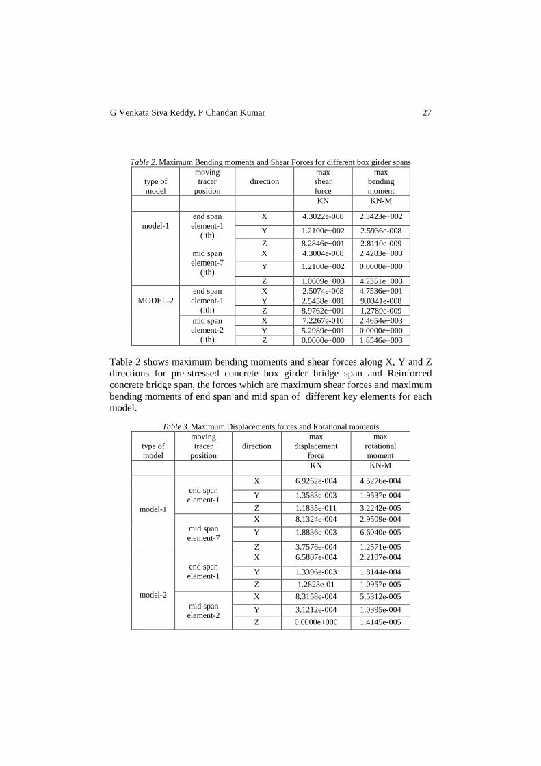
Table 2. Maximum Bending moments and Shear Forces for different box girder spans
type of
model
moving
tracer
position
direction
max
shear
force
max
bending
moment
KN KN-M
model-1
end span
element-1
(ith)
X 4.3022e-008 2.3423e+002
Y 1.2100e+002 2.5936e-008
Z 8.2846e+001 2.8110e-009
mid span
element-7
(jth)
X 4.3004e-008 2.4283e+003
Y 1.2100e+002 0.0000e+000
Z 1.0609e+003 4.2351e+003
MODEL-2
end span
element-1
(ith)
X 2.5074e-008 4.7536e+001
Y 2.5458e+001 9.0341e-008
Z 8.9762e+001 1.2789e-009
mid span
element-2
(ith)
X 7.2267e-010 2.4654e+003
Y 5.2989e+001 0.0000e+000
Z 0.0000e+000 1.8546e+003
Table 2 shows maximum bending moments and shear forces along X, Y and Z
directions for pre-stressed concrete box girder bridge span and Reinforced
concrete bridge span, the forces which are maximum shear forces and maximum
bending moments of end span and mid span of different key elements for each
model.
Table 3. Maximum Displacements forces and Rotational moments
type of
model
moving
tracer
position
direction
max
displacement
force
max
rotational
moment
KN KN-M
model-1
end span
element-1
X 6.9262e-004 4.5276e-004
Y 1.3583e-003 1.9537e-004
Z 1.1835e-011 3.2242e-005
mid span
element-7
X 8.1324e-004 2.9509e-004
Y 1.8836e-003 6.6040e-005
Z 3.7576e-004 1.2571e-005
model-2
end span
element-1
X 6.5807e-004 2.2107e-004
Y 1.3396e-003 1.8144e-004
Z 1.2823e-01 1.0957e-005
mid span
element-2
X 8.3158e-004 5.5312e-005
Y 3.1212e-004 1.0395e-004
Z 0.0000e+000 1.4145e-005

28 Response of box girder bridge spans – Influence based moving load analysis
Table 3 shows maximum Displacement forces along DX, DY and DZ and
maximum Rotational moments along RX, RY and RZ direction for two
different types of box girder bridge spans due to moving tracer. Model-B shows
minimum values when compared to model-A.
(a) (b)
Fig 6: (a) represents maximum bending moment along z-direction for key element 1-7 for model-
1 and for key elements 1 & 2 for model-2, (b) represents maximum shear force along y-direction
for key elements 1-7 for model-1 and for key elements 1 &2 for model-2.
From the above figures we can observe that bending moments and shear forces
are minimum for model-2. Hence model-2 is opted in the design point of view.
(a) (b)
Fig 7: (a) represents maximum displacements along DX, DY and DZ direction for model-1
obtained due to moving tracer for key elements 1-7, (b) represents maximum displacements along
DX, DY AND DZ direction for model-2 obtained due to moving tracer for key elements 1-3.
From the above figures we observe that displacements are minimum along the
three directions for model-2. Hence model-2 is adopted for the following design
process.

G Venkata Siva Reddy, P Chandan Kumar 29
7 RESULTS AND DISCUSSION Considering overall bending moments (z-direction), shear forces (y-direction)
and displacements (x, y and z directions), model-II is selected from the two
models.
In model-II, the vertical load resisting system provided by arrangement of
intermediate web (as shown in figure 2) reduces the live shear andbending
moments by increasing the structural resistance to the span.
This consideration helps the super structure ability to carry the vehicular live
load for particular designated lanes and also increases the safety of the structure
in the future traffic volumes.
For model-II the span/depth ratio has been reduced, subsequently decreases the
self weight of the super structure and thereby reducing the self weight moments
also.
In general considerations, prestressed concrete box girder decks are more
economical as the section is reduced when compared to reinforced concrete
decks. Selection should be based on the required construction conditions and
type of bridge firm.
PSC box girders are preferable when segmental construction is adopted as the
total number of the span is divided into independent segments and stressed
together.
RCC box girders are preferable when segmental construction is not possible.
They are casted by false work construction in the site itself.
8 CONCLUSIONS Based on the above, the following conclusions can be drawn:
(a) Multiple cell box girders are efficient means to show resisting performance
of the structure, and they provide effective means of vehicular live load
resisting system.
(b) The overall bending moments, shear forces and displacements can
effectively controlled by adopting intermediate webs of required thickness.
(c) The designer has versatility to adopt number of intermediate webs for live
load resisting.
(d) Model-II exhibits less bending moments, shear forces and displacements
when compared to model-I and is preferable for design considerations.
(e) The comparison shows only the response between the two models under
moving loads and how the bending moments and shear forces vary for
particular designed lanes.
(f) PSC box girders are mostly designed for light weight transport systems and
light rail transport system like metro rails. Whereas RCC structures are
designed for heavy loadings.
(g) Moving load analysis gives accurate live load distribution of the spans.

30 Response of box girder bridge spans – Influence based moving load analysis
REFERENCES [1] Fushun LIU, Haujan LI, Guangming YU “New Damage Location for Bridges subjected to
a Moving Load”, Journal of Ocean University of China, Vol. 6, No. 2, pp. 199-202, 2007.
[2] Adam C, Heuer R, Ziegler F “Reliable Dynamic Analysis of an Uncertain Compound
Bridge under Traffic Loads”, Springer-verlag, Acta mech 223, pp.1561-1581, 2012.
[3] MIDAS CIVIL “Model Integrated Design and Analysis”, a bridge design software 30 days
trail version
[4] Freyssinet Prestressing (pre-tensioning and post-tensioning) manual.
[5] IRC: 6-2000, Standard specification and code of practice for road bridges, section-III
[6] IRC: 18-2000, Design criteria for prestressed concrete road bridges.
[7] IRC: 21-2000, Standard specification and code of practice for road bridges, section-III
[8] IRC: SP: 64-2005, Guidelines for design of construction of segmental bridges.
[9] IRC: SP: 67-2005, Guidelines for use of external and unbounded prestressing tendons in
bridge structures.
[10] IRC: SP: 71-2006, Guidelines for design and construction of precast pre- tensioned girders
for bridges.
[11] IS: 1343-1980, Code of practice for prestressed concrete
[12] IS: 1785-1983, Specification for plain hard-drawn steel wire for prestressed concrete (part 1
cold drawn stress-relieved wire).
[13] IS: 2090-1983 specification for high tensile steel bars used in prestressed concrete.
[14] Oris H. Degenkolb., Concrete Box Girder Bridges, American Concrete Institute
[15] Krishna Raju N., Prestressed Concrete, 3rd Edition, Tata McGraw-Hill Publishing Company
Ltd., 1988.
[16] Krishna Raju N., Design of bridges 4th Edition, Oxford & IBH Publishing Co.Pvt.Ltd, New
Delhi., 2011.
[17] Johnson Victor D., Essentials of Bridge Engineering 6th Edition, Oxford & IBH Publishing
Co.Pvt.Ltd, New Delhi., 2012.
[18] Jagadeesh T R and Jayaram M A., Design of Bridge Structures 2nd Edition, PHI Learning
Pvt Ltd., 2004.
Related Documents