Zhehao Hu RESOURCE SHARING TECHNOLOGY OF CLOUD COMPUTING Thesis CENTRIA UNIVERSITY OF APPLIED SCIENCES Information Technology June 2016

Welcome message from author
This document is posted to help you gain knowledge. Please leave a comment to let me know what you think about it! Share it to your friends and learn new things together.
Transcript

Zhehao Hu
RESOURCE SHARING TECHNOLOGY OF CLOUD COMPUTING
Thesis
CENTRIA UNIVERSITY OF APPLIED SCIENCES
Information Technology
June 2016

Centria University of Applied Sciences Date
June 2016
Author/s
Zhehao Hu
Name of thesis
RESOURCE SHARING TECHNOLOGY OF CLOUD COMPUTING
Instructor
Kauko Kolehmainen
Pages
50
Supervisor
Kauko Kolehmainen
Abstract
Development of computer science and technology, application of network
education has become more mature. The technology of network learning resource
sharing has been promoted by computers. It is significant promote the
development of cloud computing education. Aiming at the need of education
resource sharing, combined with the cloud computing service model,
infrastructure and key technology. This thesis set up the educational resources
sharing system to provide high quality sharing resources for users. Cloud computing is an emerging shared infrastructure through virtualization
technology in a large number of available network resources to form a virtual
resource pool, automatic software implementation by management. Their
cross-regional, cross-database resource integration capabilities break the
scattered data resources to bring the information is not balanced, effective flow of
resources and improve utilization; For cloud nodes can be easily added and
removed and increase the size of the expansion resources to solve problems.
Meanwhile, the data in the cloud uses distributed storage, capable of storing and
accessing to share pressures, thereby improving system performance. Cloud
resources take a pay model. In this way, the user can customize the resources of
independent interest and promote personalized learning.
Key words
Cloud computing, resource sharing, infrastructure, resource pool

1 INTRODUCTION 1
2 CLOUD COMPUTING 2
2.1 Research motivation 3
2.2 Cloud computing architecture 5
2.2.1 Service model of cloud computing 6
2.2.2 Infrastructure as a service 7
2.2.3 Platform as a service 8
2.2.4 Software as a service 9
2.3 Virtualization 9
2.3.1 Virtualization infrastructure 10
2.3.2 Server virtualization 11
2.4 OpenStack framework and related technologies 13
2.4.1 OpenStack components 14
2.4.2 Python programming language 18
3 SYSTEM ARCHITECTURE DESIGN 19
3.1 System Requirement Analysis 20
3.2 System Storage Design 21
3.2.1 Storage Architecture 22
3.2.2 Proxy Server processing 23
3.3 Infrastructure Construction 25
3.4 Scheduling Strategies 27
3.4.1 Filtering Strategy 27
3.4.2 Weights computing strategy 29
3.5 System level model 29
3.5.1 Logical layer 31
3.5.2 Support layer 32
3.5.3 Educational resource sharing system architecture 32

3.6 System implementation process 34
3.6.1 System performs logic 35
3.6.2 System physical architecture 37
3.7 Summary 38
4 PLATFORM TECHNOLOGY 38
4.1 Logic layer implementation 40
4.1.1 Scheduling process 42
4.1.2 Scheduling related classes 43
5 CONCLUSION 49
6 REFERENCES

1
1 INTRODUCTION
The rapid development of information technology has long-term impact on all areas
of human life, including education. The fast development of long-distance
education promotes the education of informatization process, and play an
important role in promoting the popularization of higher education, the
construction of the national education system and the learning of social services,
and construction of lifelong education system.
The building of education resources is the foundation and core of distance
education. Concerned with the education resources construction to enhance
education resources management is an extremely urgent task. The number of
learning resources grow rapidly. But the quality of resource is uneven, duplicate
resources seriously lack of effective organization and management. Education
resources are in a highly dispersed and disordered state, reducing the utilization of
resources and affected the effective of sharing resources, which has become a
major problem for the construction of education resources in information
technology. The main research contents and achievements of this thesis are as
follow. To learn the traditional method of educational resource sharing, and to
analyze problems. Then analyze of key elements and techniques to build an
educational resource sharing system based on cloud computing. Learning could
computing, virtualization, IaaS and OpenStack theory and related technologies.
Researching system architecture of cloud computing, and integration of the existing
physical infrastructure, then building a cloud computing infrastructure with the
OpenStack open source project to form a resource pool and providing external IaaS
services. Analyzing of demand resource sharing system gives the overall
2
architecture of system, and applies the detailed design and analysis for each
function level. Design of the overall program, technical implementation of all levels,
and researching key issues, such as scheduling policy implementation, customized
access interfaces, and gives detailed solutions. Final stage is testing and analyzes
the system.
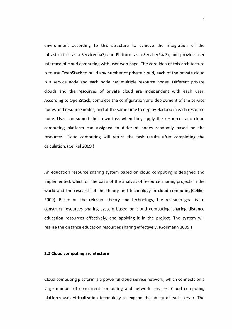
2 CLOUD COMPUTING
Cloud computing is an emerging model of Business Computing. It distributes
computing tasks in a resource pool which consists of many computers, so that
various applications can access the cloud as they need. For example computing
ability, storage space and a variety of software services. Cloud computing is the
product of grid computing, distributed computing, parallel computing, utility
computing, network storage and load balancing traditional product development of
computer technology and network technology. (Gollmann 2005.)
In the early 1960's, McCarthy (John McCarthy) proposed to make computing power
the same needed as electricity and water utilities to the user. The concept of cloud
concern about various areas , Amazon, IBM, Intel, Microsoft, Yahoo, SUN, EMC,
Google and other large IT companies invest in the construction of cloud computing
platform, provide the corresponding cloud computing services. Cloud computing is
defined as a business-friendly operation mode in this mode, users can run their own
applications in a shared data center, use these data-centric applications, simply by
logging and customization. (Gollmann 2005.)

3
Cloud computing is a shared network information delivery model, the users do not
need to care about the cloud infrastructure. The so-called "cloud" is an infinite
resource pool which is a virtualization concept. Both hardware and software
resources are packaged as services, users can access and use it through the Internet
on-demand. From the user's point of view, these resources are unlimited, can be
expanded and configured dynamically. These resources exist distributed in physics,
but in the end the logic is presented in a single integral form. Users do not need
autonomy to manage these resources, but demand the use of cloud resources while
paying according to actual usage. (Gollmann 2005.)
2.1 Research Motivation
OpenStack is an open source projects tool set of cloud computing , and
Infrastructure as a Service (IaaS) solution. The OpenStack can quickly deploy
virtualization environment, and through this environment create multiple
interconnected virtual server, and users are able to quickly deploy applications on a
virtual machine. In addition, Hadoop as an open-source service(PaaS) distributed
computing architecture which provides by the Apache-based platform has been
successfully applied in Amazon, Facebook, and other large sites abroad. The core
design of Hadoop is MapReduce and HDFS. MapReduce is designed to decompose
the task into several sub-tasks to the node processing respectively, and return the
results to the main node. HDFS is named the Hadoop Distributed File System, which
provide underlying support for distributed storage. (Gollmann 2005.)
The focus of this study is to use OpenStack to build a cloud computing architecture
which is based on Infrastructure as a Service(IaaS), and also to build a Hadoop
4
environment according to this structure to achieve the integration of the
Infrastructure as a Service(IaaS) and Platform as a Service(PaaS), and provide user
interface of cloud computing with user web page. The core idea of this architecture
is to use OpenStack to build any number of private cloud, each of the private cloud
is a service node and each node has multiple resource nodes. Different private
clouds and the resources of private cloud are independent with each user.
According to OpenStack, complete the configuration and deployment of the service
nodes and resource nodes, and at the same time to deploy Hadoop in each resource
node. User can submit their own task when they apply the resources and cloud
computing platform can assigned to different nodes randomly based on the
resources. Cloud computing will return the task results after completing the
calculation. (Celikel 2009.)
An education resource sharing system based on cloud computing is designed and
implemented, which on the basis of the analysis of resource sharing projects in the
world and the research of the theory and technology in cloud computing(Celikel
2009). Based on the relevant theory and technology, the research goal is to
construct resources sharing system based on cloud computing, sharing distance
education resources effectively, and applying it in the project. The system will
realize the distance education resources sharing effectively. (Gollmann 2005.)
2.2 Cloud computing architecture
Cloud computing platform is a powerful cloud service network, which connects on a
large number of concurrent computing and network services. Cloud computing
platform uses virtualization technology to expand the ability of each server. The

5
respective resources are combined with the processing and storage of data through
cloud computing platform , which are also completed by passing "cloud" side of the
server cluster. A large data processing center is responsible for unified management
and providing super computing storage capacity. (Jain 2008.)
Cloud computing architecture model is shown in Graph 1
Cloud ClientManagement
Systems
Deployment
Tool
Service Catalog
Resource
Control
Server Clusters
Graph 1 Cloud computing architecture model (Jain 2008.)
In the above architecture users can login, customized services, configure and
manage through a Web browser. Users obtain appropriate rights, which means
users can customize the list of services or unsubscribe the customized service. User
selects the desired service after verifies the scheduling of resources, intelligent
deployment of resources and applications, and then the server sends a request to
the management system. And real-time monitor system will monitor, rapid
response and complete synchronization between nodes of cloud platform resources
and also load balancing configuration to ensure the smooth and effective allocation
6
of resources to the right users. The server cluster is a management system for
unified management of the virtual or physical servers, responsible for the user
request processing, while providing powerful computing ability. (Jain 2008.)
2.2.1 Service model of cloud computing
National Institute of Standards and Technology (NIST) considers that cloud
computing has five basic characteristics: demand self-service, broad network access,
resource sharing pool, rapid expansion and pay-per-use. There are four cloud
computing deployment models as private cloud, community cloud, public cloud and
hybrid cloud according to different purposes. Private cloud is generally used alone
as an institution established. Community cloud is for a number of organizations with
one common concern. Public cloud is created by the cloud service provider, the
average user or large enterprise group rented cloud resources through the network.
The hybrid cloud is composed of two or more clouds composed of these clouds to
keep their independence from each other, bound together by standardized or other
technologies to provide more convenient services. (Sandhu 1996.)
No matter what kind of deployment model, according to the type of service can be
divided into three categories: Infrastructure as a Service (IaaS), Platform as a Service
(PaaS) and Software as a Service (SaaS). (Sandhu 1996.)

7
Graph 2 the cloud service models ( Sandhu 1996.)
2.2.2 Infrastructure as a service
IaaS means the infrastructure such as hardware devices encapsulated into service
for users. For example elastic compute cloud EC2 and simple storage service S3 of
Amazon Cloud AWS. These computer infrastructures mainly use for data processing,
storage, networking and other basic computing resources. Users can deploy and run
the software without understanding the underlying cloud infrastructure, but need
to manage the operating system. Storage the application deployment and network
components requires moderate concern. IaaS’s advantage is that IaaS allows
multiple users to dynamically apply or release the node. So the user can be able to
apply almost unlimited resources of the task. At the same time, IaaS is shared to the
public, so it has higher resource utilization efficiency. ( Sandhu 1996.)
2.2.3 Platform as a service
PaaS refers to the deployment in the cloud infrastructure platform as a service
provided to users. In this service mode, the PaaS platform provides the required
application development programming languages and tools. Without focusing on

8
the bottom of the cloud infrastructure, including network, servers, operating
system and storage, users only need to use the platform to create, acquire and
deploy applications, and configure the application of client demand environment.
The typical PaaS such as Microsoft cloud operating system Microsoft Windows
Azure. PaaS dynamic expansion and fault management is responsible for its own
resources. User application does not have too many issues to consider with
between nodes. (Weber 1997.)
The implementation of PaaS is to encapsulate middleware platform, other
components and operating environment. The developers can develop the software
according to their own needs and customize their own development platform.
Developers can concentrate on the application without considering the scalability or
service capacity of application. PaaS also provides a platform for the user. As long as
the deployment to the PaaS platform can be run in accordance with the lease
system, the users don’t need to care about the configuration of hardware or
software system. PaaS provides management function which can help developers to
monitor and bill application. Application development and speed are based on the
same platform which reduced compatibility issues between applications. (Zhang
2008.)
2.2.4 Software as a service
SaaS(Software as a service) is different with PaaS, SaaS is more targeted that
providing computing or storage resources service. And SaaS is also different with
IaaS which provides a running environment for users to customize the application
Saas only provides some special services for application calls. (Zhang 2008.)

9
SaaS Provider deploys unified application software on the server according to their
actual needs. Customers can order the necessary application software to the server
through the Internet service provider. In this mode, the user can order the software
without the need for maintenance of the software anytime anywhere. Service
provider solely responses for the management and maintenance of the software,
and also provides off-line operation and local data storage to users. For small and
medium enterprises, SaaS provides one of the best ways to use advanced
technology. It completely eliminates the need of enterprise purchase, construction,
maintenance of infrastructure and applications. SaaS orients multiple users
simultaneously, but each user has an exclusive feel like the service. (Zhang 2008.)
2.3 Virtualization
Virtualization accompanies by the emergence of computer technology. In 1859,
Christopher Strachey published an academic report andnamed “Time sharing in
Large Fast Computers”. He first proposed the basic concept of virtualization in the
text. And this is the first time the concept of virtualization has been proposed. The
early development of virtualization technology is to use it in large machine field.
IBM L.W.Comeau and.J.Creasy designed the new operating system called PC-40 in
1964, and achieved the virtual memory and virtual machine. In 1972, IBM released
a virtual machine (VM) which is used to create a flexible mainframe technology,
which could achieve the use of resources according to the needs of the dynamic
effects rapidly and efficiently. (Davey 2002.)
Virtualization is a broad concept The computer components are not running on real
hardware facilities, but running in a virtual environment. This solution is designed to
optimize resources and to streamline management. It simplifies the process of
reconfiguring the hardware capacity while expanding. Virtualization makes the

10
complex resource access management processing becomes simplified. It is not
restricted and constrained by the physical device. Vitualization is the logical
representation of the resource. Virtual resources unify management of physical
resources through standard interface. The interaction between the physical
memory and virtual resources is illustrated by basic patterns of virtualization.
(Davey 2002.)
2.3.1 Virtualization infrastructure
Virtualization technology is an important basis for cloud computing and cloud
storage of the data center. It makes data center computing power more scalable
and flexible the accessing of data, also easier and better for manage cloud
computing services. Virtualization makes physical resources of infrastructure
dynamically map to the drive of the application. Virtualized infrastructure creates a
virtualized pool of resources, unifies management servers, storage and networks.
The needed resources in the resource pool can be called at any time according to
the application. At the same time, the resources on a single physical machine can be
shared between virtual machines. Virtualization infrastructure can reduce capital
and operational costs, and optimize the combination of resources to achieve
greater flexibility. (Davey 2002.)
Virtualized infrastructure is shown in Graph 3.

11
Server Network Storage devices Network equipment
Application
program
Application
program
Virtual machine operating system
Virtual machine operating environment
Application
programApplications
Virtual machine operating system
Virtual machine Virtual machine
Graph 3 Virtual infrastructure (Davey 2002.)
Virtualization infrastructure separates oftware environment and hardware
infrastructure from each other. This can make multiple servers, storage and
network polymerize into the shared resource pool. Virtualization infrastructure
provides dynamic pool of resources to the application safely and reliable according
to the needs of the user. Users can use inexpensive industry-standard servers to
build self-optimizing data center. Virtualization infrastructure creates dynamic
shared platform services to achieve a high level of efficiency, security, availability
and flexibility, and can be integrated with distributed hardware resources. (Davey
2002.)
2.3.2 Server virtualization
Virtualization can be divided into server virtualization, storage virtualization and
network virtualization according to the domain of application. The core of storage
virtualization is mapping physical storage devices into a single logical storage

12
resource pool. It unifies various heterogeneous storage resources to a single view of
the resource for users. Network virtualization refers to the integration of hardware
and software resources of the network to provide users with a virtual network
connection. Server virtualization is the application of virtual technology in the
server. A server is divided into a plurality of virtual servers, which provides
hardware abstraction and virtual server management through of virtualization
software. Server virtualization follows the virtual infrastructure and construction of
the cloud platform, which is based on server virtualization. (COLANTONIO 2011.)
The essence of server virtualization is the introduction of a layer of software and
virtual machine monitor (VMM). It is responsible for the virtual machine to provide
hardware resource abstraction and provide the necessary environment for the
client operating system. The virtual machine monitor can isolate the underlying
hardware and application, which makes the application deployment more flexible
and no longer subject to the limitation of hardware environment. (Davey 2002.)
Server virtualization’s architecture is shown in Graph 4.
Graph 4 server virtualization (Loomis 2010.)

13
There are three typical characteristics of server virtualization technology.
Multi-instance means that server virtualization can run multiple virtual servers on
one physical server(Loomis 2010). In the multi- instances server virtualization, the
virtual machine is completely isolated from each other. With the help of isolation
mechanism, even if one or several virtual machine crashes, it will not affect the
other virtual machine. The data leakage cannot occur between virtual machines.
When multiple virtual machine needs to process or application needs to access each
other, it will be done for the configuration of the network, and takes the same
virtual before several independent physical server communication modes. (Loomis
2010.)
After the adoption of server virtualization, a complete virtual machine environment
becomes a single entity. These entities make backup and replication more
convenient between the different hardware. At the same time, server virtualization
physical hardware is packaged into standard virtual hardware devices to provide the
operating system and application program inside virtual machine. (Loomis 2010.)
2.4 OpenStack framework and related technologies
OpenStack is collaborated by the U.S. National Aeronautics, Space Administration
and Rackspace research. With the Apache license and it becomes a free software
and open source project. It is a cloud operating system, used to manage a large
resource consisting of computers, storage devices and network resources. It
provides a platform to deploy cloud, call toolset designed to help organizations
running as a virtual computing or cloud storage services for a whole cloud. The

14
private cloud provides flexible and scalable computing. OpenStack is an open source
project, which has more than 130 communities and 1,350 corporate developers.
These organizations and individuals regard OpenStack as infrastructure and services
(IaaS) generic front-end. (Loomis 2010.)
The primary task is to simplify the deployment process of OpenStack cloud, bring
their good scalability and also get strong support of NASA and Rackspace, which
also includes Dell, Citrix, Cisco, Canonical, HP and IBM. With their contribution and
support the development has been very fast and OpenStack replaced another
industry-leading cloud platform Eucalyptus. OpenStack consists of two major
modules, Nova and Swift. The former is the NASA virtual server deployment and
Business Computing module; The other is distributed cloud storage module of
Rackspace development. Both of them can be used together or separately. In
addition, there are some auxiliary projects including, Quantum, Cinder, Keystone,
Glance and Horizony. (Loomis 2010.)
2.4.1 OpenStack components
Since October 2010, OpenStack released Austin, Bexar, Cactus, Diablo, Essex and
Folsom and six other versions. OpenStack uses modular design. The main module is
Nova (service), Swift (storage service) and Glance (mirror). They can be combined in
a joint work together and provide cloud infrastructure service . They can also work
independently. Nova is responsible for cloud computing tasks, swift is responsible
for permanent data storage and Glance responsible for unifying management of the
mirror. In addition, the modular is design to integrate the old hird party technology
and in order to meet the business needs, also makes it easier for developers to

15
develop OpenStack(COLANTONIO 2011). The overall architecture of OpenStack is
shown in Graph 5
Graph 5 The whole architecture of OpenStack (Colantonio 2011.)
OpenStack Compute (Nova) is a controller for providing a virtual machine instance
management for individual users or groups. It can also be used to set up a network
for a specific project, which contains multiple instances. Throughout architecture,
Nova is responsible for the entire resource, networking and cloud computing,
although Nova does not provide any virtual capacity. But it uses the liberty API and
virtual machines to interact with the host. Nova provides external interfaces
through the API, which are compatible with Amazon's Web service interface. Nova
is mainly composed of the following components: API Serve (rNova-API), a message
queue (Rabbit MQServer), computer nodes (Nova-compute), Network Controller
(Nova-network), volume management (Nova-volume) and scheduler

16
(Nova-scheduler). API Server provides interactive cloud infrastructure interface with
the outside, it is the only management channel of outside cloud users. OpenStack
internal message queue is the follow AMQP (Advanced Message Queuing Protocol)
on the basis of communications. Nova response to the request for asynchronous
calls. When the request is received trigger will callback immediately. Because of the
using asynchronous communication, the user will not have to be placed in a waiting
state for a long time operation. (Colantonio 2011.)
The main task of computing nodes is management examples throughout the life
cycle, which receives the request through the message queue and executes on the
instance to perform various operations. In a typical production environment there
will be multiple computing nodes, according to the scheduling algorithm. An
example of computing nodes can be deployed in any possibility. (Colantonio 2011.)
The network controller deals with the host network configuration, such as the
allocation of IP address, configuration item VLAN, set the security group as well as
the computing node configuration network. Volume workstation management
examples of LVM based volume can create additional volumes, as a case, delete,
and also can roll separation from one instance. Volume management provides a
instance persistent storage which means the present scheduling algorithms are
mainly: randomized, availability and simplified categories. OpenStack Storage (Swift)
provides object and block storage capabilities for server or application. It is a
large-capacity, scalable, built-in redundancy and fault tolerance mechanisms of
object storage systems. (Colantonio 2011.)
Swift can provide scalable storage cluster redundancy by configuring a normal hard
disk standard servers. It’s not only represents a file system, but also to achieve a

17
more traditional object storage system which can be used for long-term storage of
static data. Swift does not have a centralized controller. Swift can improve the
overall scalability through replication across a cluster of internal management to
improve the reliability. (COLANTONIO 2011.)
OpenStack Image Service (Glance) provides a virtual disk mirroring for Nova. Glance
provides the API to register the disk image, also available through a simple
Representation State Transfer (REST) interface mirror discovery and delivery. It
supports a variety of standards, including VDI (virtualBox), VHD (Microsoft Hyper-V),
QCOW2 (QEMU/KVM), VMDK/OVF and native format. Glance also provides a disk
image checksum, version control, and other metadata of virtual disk verification.
(COLANTONIO 2011.)
In addition, there are two main auxiliary projects of Keystone and Horizon. Keystone
is a OpenStack authentication server. It provides authentication and access policy
services for OpenStack components. .It relies on its own REST (based IdentityAPI)
systems, mainly for Swift, Nova and Glance. Authorization verifies the legality of
actions by a source who requested messages. Keystone is mainly in two Licenses:
username, password and token (Token). Keystone offers the following three
services: Token Service (authorized user authorization information), directory
services (the list of available service users legitimate operations) and strategic
services (use keystone specific access rights specified users or groups). Horizon is a
Web interface of OpenStack management and web Control Panel for managing,
which is controlling OpenStack service. It can manage instances, mirroring, create
the key pair instances add volume, operating Swift containers. In addition, users can
also use VNC terminal or directly access the control panel instance. (Colantonio
2011.)

18
Relationship between OpenStack components is shown in Graph 6. (Colantonio
2011.)
Horizon
Glance
Keystone
Nova Swift
management
interface
Mirroring
get
Mirrored
Storage
Identity
authentication
Graph 6 OpenStack component relationship
2.4.2 Python programming language
Most components of OpenStack Compute performance (Nova) is based on the
Python language daemon. Python is an elegant and robust programming language.
It inherits the traditional compiled language, powerful and versatile. Python is an
object-oriented, literal translation of programming languages, is also a powerful
general-purpose language, and has already nearly two decades of development
history. It contains a comprehensive set of standard libraries also it is easy to
understand and easy to complete many common tasks. Syntax is very simple and
clear, and most other programming languages that do not use braces. Syntax uses
indentation to define block. (Davis 2007.)
19
Python supports imperative programming, object-oriented programming, functional
programming, aspect-oriented programming and generic programming. For
instance, dynamic language Scheme, Ruby, Perl and Tcl. Python virtual machine can
run on all operating systems. (Davis 2007.)
Python is often used as a scripting language processing system and network
administration tasks for the program. In addition, it also has a wide range of
applications in the fields of the graphics processing, mathematical processing, text
processing, database programming, Web programming, multimedia applications,
hackers and other senior programming. (Davis 2007.)

20
3 SYSTEM ARCHITECTURE DESIGN
The goal of this thesis is to establish an educational resource sharing system
combined with OpenStack project and supported by cloud computing technology.
The system will unifying server, network, storage device and distributed hardware
resources. By using virtualization technology to form a unified hardware resource
pool for management open source components by the OpenStack. The system
provides IaaS services and users can rent IaaS resources or storage resources.
Development of the deployment educational resources sharing system can provide
access to educational resources interface to administrators and students. The
functional requirements of the system are as follow: The system can organize
physical resources that disperse in the computer or server on the network to form a
unified resource pool for unified management. The system is base on the basic
architecture of cloud computing and provides a visual interface for unified
management. The system provides interface for user registration. Registered users
can lease cloud resources and allocate the use right of resources. At the same time,
the system will verify the identity of the user and the user authority of resources for
system safety. When registration is complete, users can rent cloud infrastructure
according to their needs. The system will provide a visual interface (Web) to
monitor the resources. According to personal needs, users can customize or upload
system images, store educational resources, and deploy educational resource
sharing system, users can upload their own educational resources to the hired
infrastructure. And resources are able to adding, deleting, modifying, querying and
configuration by user. (Vaidya 2010.)
The system provides a distributed storage scheme for unifying the educational
resources which is similar to file management. The storage of system is according to

21
replication configuration, at the same time updates the replicas. When the system
is overloading, the system can quickly find the storage nodes which are available to
answer the user’s requirements. (Vaidya 2010.)
3.1 System Requirement Analysis
According to the resources openness and sharing principle, the education resources
sharing system is designed to provide resource retrieval, upload, download,
management, and evaluation service. The system aims to find and share better
learning resources. The system is built by the following demands, using fast and
effective sharing principle to find useful educational resources. Nowadays, the
traditional network technology resources sharing system is not fully functional. For
example the utilization rate of database, hardware, and resource are low. The cloud
computing technology is basing on virtualization technology and carries on the
management to the existing hardware resources with the aid of the open source
project. The owner can provide IaaS service for the vast number of resources. Users
can rent a pool of resources according to their own need. At the same time
resource is can be customized by the needs of Web console in OpenStack, to
monitor their rented resource usage. (Vaidya 2010.)
In this system, the user does not need to consider the management of resources.
The sharing system will unify management the learning resource, personal
information and retrieval of records. The user can retrieve their learning resources
anywhere. The platform should also monitor and calculate each resource node of
each virtual resource, and reflect the status of each node to the administrator.
When a node fails, there should be a specialized module to try to recover the node,
while the user request is forward to the node to guarantee the quality of service. At

22
the same time, when the user request is arrived, the system should ask the storage
node forwarding to the fastest speed to responding to user requests and processing
nodes in all alternatives. (Vaidya 2010.)
3.2 System Storage Design
Storage resources have an enormous influence on the sharing scale. This chapter is
analyzing the traditional storage methods, summarizing the deficiencies, and
proposing demands of the need to implement the function and storage solutions.
(Han 2006.)
Previous teaching resources store system user can not access to the system if the
resource is damaged. The reliability of the system is low. The data is storage in
distribute way in the system. Teaching resources need to split into data pieces for
scattered storing in the cloud nodes. In the same time, the system adopts a copy
backup mechanism and each data block has several copies stored at different nodes.
Even if one day the error occurred, it will not affect the integrity of the resources,
which is increasing the reliability higher. (Han 2006.)
Generally teaching resources is usually storage in a single server. When the server is
down, users can neither store resources nor access resources. The system is
combined with distributed storage structure cloud computing. The cloud has a
control node; the main function is real-time monitoring of the storage node state.
When the storage node is failing, the control node will request user to normal
operation node to complete the task. (Han 2006.)

23
Usually the teaching resources are stored in a professional storage device. The price
of professional storage equipment is expensive and it will increase storage resource
costs. Therefore, for system storage equipment should choosing commercial
machine. The system uses virtualization technology provides unified management
for storage scheme as professional storage equipment for the user. (Han 2006.)
The system should meet the need of dynamic management storage nodes. The
storage node can be added and removed dynamically and easily adjusting the
capacity of storage without affecting the original data. The original storage mode of
teaching resources is centralized single point; when a large number of users store or
access data, it will cause equipment pressure and influence the system performance.
Due to the use of the distributed storage, this system can balance the store and
access pressure for improve system performance. (Han 2006.)
3.2.1 Storage Architecture
Resources sharing system is based on cloud computing and using the virtual
technology to make the server, storage devices and other hardware as a pool of
resources. Allocate these resources according to the needs. Storage architecture
uses a distributed architecture in order to avoid single point of failure and
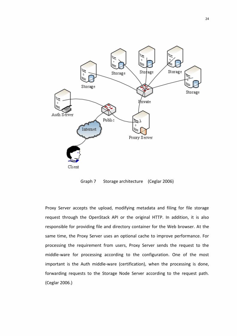
horizontal expansion. (Ceglar 2006.)
The basic storage architecture of the system is shown in Graph 7.
24
Graph 7 Storage architecture (Ceglar 2006)
Proxy Server accepts the upload, modifying metadata and filing for file storage
request through the OpenStack API or the original HTTP. In addition, it is also
responsible for providing file and directory container for the Web browser. At the
same time, the Proxy Server uses an optional cache to improve performance. For
processing the requirement from users, Proxy Server sends the request to the
middle-ware for processing according to the configuration. One of the most
important is the Auth middle-ware (certification), when the processing is done,
forwarding requests to the Storage Node Server according to the request path.
(Ceglar 2006.)
25
Object Server is responsible for storing, retrieving, and deleting local stored object
data. Container Server can list all objects in the container. The default list of objects
will be stored as MySQL files. Storage cost and other relevant information will also
include in the statistics object container. Account Server is responsible for managing
and maintaining the server. (Ceglar 2006.)
The storage architecture and framework can use OpenStack Swift to provide open
source. Users can call the API to provide on Account Server, Container Server, and
Object Server for co-processing. Swift itself will contains some daemons about the
interaction between the coordinate management. (Ceglar 2006.)
3.2.2 Proxy Server processing
Entire storage architecture is use Proxy Server to accept and process user request,
and give authorization and authentication to users. Then forwards the request to
the appropriate service routine (Object, Container, account) for processing,
receiving requests and returning results to go through Proxy Server, however, Proxy
Server is not able to caching the data. (Ceglar 2006.)
Proxy Server process graph is shown below.

26
Graph 8 Proxy Server process (Ceglar 2006.)
When a user requests access is arriving to the Proxy Server then the authentication
process is as follow: User can have authentication through Auth. The validation
service will generate a user token. System verifies each request and authorization
through the token. For this step, the case will be executed only when the user
provide an invalid token. In general, the duration of the token is configurable. Since
user initiates the second request to the Proxy Server, about the header information
in the HTTP request is containing token. Proxy wills verification the token, after
verification, the process request to account, container and object. For the
verification the server can use WSGI middle-ware, WSGI is also can be used as an
independent system. Keystone in the open source projects of OpenStack is using for
all OpenStack components to provide authentication and access policy. It depends
on the work in the REST system, and follows the direct use of keystone verification.

27
No matter the account, Container and Object is all responsible for handling user’s
information. Request for a PUT/account/container/object of Proxy Server is
querying the ring file, upon request, to obtain the Object storage node list, then the
request is forwarding to three nodes. If it only has two nodes write successful, then
this PUT operation is successful. After a period of time, the failure node will be
written to the success node object-replicator to process to the data. (Ceglar 2006.)
In the same time, Swift is also provides the update process. It runs on the storage
node and it is responsible for the asynchronous update of the database. The reason
for using asynchronous update is when it is dealing excessive requests; container or
object service program cannot update the database for real-time processing of the
request. These requests can be localized at the queue, thus the update process is
asynchronous updates. (Ceglar 2006.)
3.3 Infrastructure Construction
A compact data structure can be designed based on the following observations.
To build the IaaS, need to follow the demands to install the required components to
combine with the infrastructure environment. First of all is analyzing the existing
hardware environment to determine the type of operating system. Secondly is
installing the authentication server. After this installation and configuration of
computing services and mirroring service is completed. Finally is installing the
storage service and Web control terminal. (Han 2004.)
OpenStack supports RHEL, CentOS, Fedora and Ubuntu. It needs to select Ubuntu
Server 12.04 as operating system, and the OpenStack Folsom version is needed. The
authentication services are provided by the OpenStack Keystone component. It has
two main functions: first is called user management. It means tracking and

28
monitoring of user behavior. Second is called service catalog. It provides available
services catalog and API endpoint's location for the user. After the authentication,
the users are divided into Users, Tenants, and Roles. The Operator can use the
command line to manage. Also it can modify etc/nova/policy.json file for using
unified management. (Han 2004.)
Mirroring service is provided by OpenStack Glance component mainly includes
configuration and installation function. The configuration is back-end database and
mirroring service. The installation of OpenStack Nova is the most important part. It
is divided into two types: node control and node compute. The node control is used
to manage the latter. The detail procedure is showing below. (Han 2004.)
Installin
g o
peratin
g sy
stem
Installatio
n an
d C
on
figu
ration
no
de co
ntro
l datab
ase
Install co
ntro
l no
de
Co
mp
uter n
od
e con
figu
ration
Co
mp
uter n
od
e datab
ase creation
Co
mp
uter C
on
figu
ration
no
de n
etwo
rk serv
ices
Co
mp
uter n
od
e mirro
r pro
du
ction
Sig
n v
irtual m
achin
e mirro
r
Co
mp
uter n
od
e con
trols asso
ciated n
od
es
Add computer node
Graph 9 Computing nodes installation and configuration process (Han 2004.)

29
Object storage is provided by the OpenStack Swift component. It is used for store
images. The Dashboard is provided by OpenStack Horizon. It is used to provide a
Web management interface. Those two components are optional. (Han 2004.)
After the above steps, an IaaS platform is successfully constructed. Every user needs
to login to their own account. The platform will choose a different configuration
(CPU, memory, disk) example from the mirror, distribution IP, open port, login, fully
autonomous operation. The user can install software, deploy application, and store
data. (Han 2004.)
3.4 Scheduling Strategies
When creating instances in the start-up scheduling strategy, each computing node
has a certain amount load. According to the user’s specified requirements, the
computing node can create a virtual machine instances as fast as possible, and try
to balance the nodes of CPU, I/O and network load. ( Han 2004.)
Combined with OpenStack default scheduling policy, this section will devide the
scheduling process into two steps. The first step is the filter unavailable nodes. The
second step is seek and weight the available computing nodes, choosing the best
computing nodes to create a virtual machine instance. ( Han 2004.)
3.4.1 Filtering Strategy
Filtering strategy goal is to filter the unavailable computing nodes in order to find
out the available computing nodes that meet the needs of user’s requirements. For

30
reduce the waiting time. There are two main filtering strategy executive bases: the
availability of computing nodes and the user instance needs. (Han 2004.)
The filtering process is divided into the following steps. Configuration hardware
according to user requirement and determining which node is available. According
to the user specified the instance type and management type to determining
whether the node meets the requirements, then using custom filter and filter nodes.
Filtering specific parameters and order are shown in Graph 10. (Han 2004.)
Read the user instance
configuration information
Get VCPU number
Enough VCPU
Read RAM size
Enough RAM
Need second step
judgement
Failure
Read instance architecture
Coincidence
Read management program type
Success
Exist
Successful
execution
Coincidence
Defined filters
Read the json
file
Yes
Yes
No
No
Yes
Yes
YesNo
Yes
Yes
Yes
No
Graph 10 Filtration steps (Colantonio 2011.)

31
In the above graph, the architecture of the instances can be specified by the user in
the second step judgment, including the i386, x86_64, arm and PowerPC.
Management program type is determined by the image format, such as Xen and
Kvm. The third step shows user-defined filters which is means that the user can
customize the filter script in json format. OpenStack can provide json interpreter.
The map marking computing node in the second step is for weight calculation,
sorting and selection of the optimal computing node to create virtual machine
instances for users. (Colantonio 2011.)
3.4.2 Weights computing strategy
If there is only one computational node after the computing nodes complete
filtering strategy selection, need to skip this step directly back to the node to create
a virtual machine instances. Otherwise, it needs to calculate weights again.
According to the weights, sort each node and select the minimum weight node as
the optimal computing node to create virtual machine instances. (Colantonio 2011.)
To create an instance for computing nodes is depends on the filtering strategy and
weight calculation strategy. For example if the filter is completed, and the available
computing node set is empty, this means there is no computing nodes which is
meet the conditions. Instance state creation is fail. Even if the final target
computing nodes have been found, but the accident also leads to failure of instance
creation, like the network anomaly and power problem. System need to make a
problem report for future updating use. (Colantonio 2011.)
3.5 System level model
32
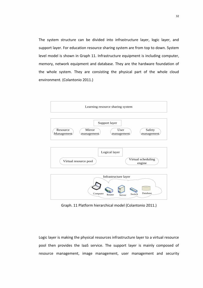
The system structure can be divided into infrastructure layer, logic layer, and
support layer. For education resource sharing system are from top to down. System
level model is shown in Graph 11. Infrastructure equipment is including computer,
memory, network equipment and database. They are the hardware foundation of
the whole system. They are consisting the physical part of the whole cloud
environment. (Colantonio 2011.)
Learning resource sharing system
Resource
Management
Mirror
management
User
management
Safety
management
Support layer
Logical layer
Virtual resource poolVirtual scheduling
engine
Infrastructure layer
ComputerRouter Server Switch Database
Graph. 11 Platform hierarchical model (Colantonio 2011.)
Logic layer is making the physical resources infrastructure layer to a virtual resource
pool then provides the IaaS service. The support layer is mainly composed of
resource management, image management, user management and security

33
management. It is a bridge between the virtual network and application system.
Education resource sharing system is providing educational resources sharing
service for cloud users such as students, teachers and learning center. (Colantonio
2011.)
3.5.1 Logical layer
Logic layer makes the physical resources can be converting into virtual resource
pool in order to hide the complexity and dynamicity of the infrastructure layer. It
can sharply reduce the complexity of management. It also improves the efficiency
of resource utilization and operation and reduces control costs. (Colantonio 2011.)
When the user rent IaaS services, logic layer is responsible for creating virtual
machine instances for the user. The user should first judge authority before creates
an instance. When an instance is created, the system will generate a copy. After the
instance runs, the system will be updating while users make any operation to save
and protect user resources. The specific logic layer action is shown in Graph 12.

34
User registration
Registered mirrorApplication
resources
Upload mirror
Mirror
Copy mirror
Mirroring Installation and
Configuration
Start the instance
Instances running
Examples end
Successful
applicants
Mirroring does
not exist
Graph 12 Logic layer implementation steps (Colantonio 2011.)
3.5.2 Support layer
The support layer is mainly responsible for user interaction with the resource pool.
User need to determine the number of instances that need to open and the
configuration parameters for each instance according to their own needs. Resource
pool are consisting from computing nodes and the support layer will assign needed
resources when the instance runs and start and manage instances based on the
35
instance standard configured by the users. During this time support layer is
responsible for resource pool management and extension work. It monitors the
running state, managing the instance in real time, detect and authentication for the
user’s behavior. The composition of the support layer is resource management,
image management and security management, user management. (Colantonio
2011.)
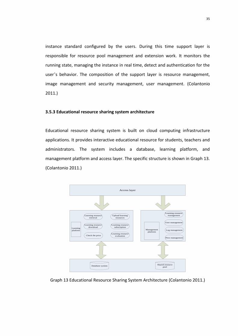
3.5.3 Educational resource sharing system architecture
Educational resource sharing system is built on cloud computing infrastructure
applications. It provides interactive educational resource for students, teachers and
administrators. The system includes a database, learning platform, and
management platform and access layer. The specific structure is shown in Graph 13.
(Colantonio 2011.)
Access layer
Learning resource
retrieval
Upload learning
resources
Learning resource
download
Learning resource
subscription
Learning resource
evaluationCheck the price
Learning
platform Management
platform
Learning resource
management
User management
Log management
Price management
Database systemShared resource
pool
Graph 13 Educational Resource Sharing System Architecture (Colantonio 2011.)

36
Access layer is receiving and responding for user requests. When the user is logged
in, the system will first verify the identity, second verify the user permissions.
According to the user's permission and system position that user can login to
systems and access interface. (Colantonio2011.)
Learning platform provides educational resources sharing service for students.
Students can search the existing education resources and subscribes interesting
resources. Resources subscription fee is decided by the student user group.
(Colantonio 2011.)
The user case diagram of students and learning interactive platform is shown in
Graph 14.
Login system
Not subscribe resource
list
Subscribed Resource
List
Learning Resources
Management
Learning Resources
Subscribe
Learning Resources
Retrieval
Check the price
Learning Resources
unsubscribe
Learning Resources
Evaluation
Learning Resources
Download
Learning Resources
upload
I
I
I
I
I
I
I
I=include
Student
Price management
Graph 14 Learning platform use case diagram (Colantonio 2011.)
Management platform provides the platform for managers to unify the
management the education resources and students. It includes educational

37
resources management, user management, log management and tariff
management. Specific use case diagram is shown in Graph 15. (Colantonio 2011.)
Login system
Log Management
Price management
Learning Resources
Management
User Management
Learning Resources
Audit
Learning Resources
upload
Learning Resources
Statistics
Learning Resources
Retrieval
User information
query
User permission to
modify
I=include
Administrator
Query log
Log statistics
Standard
Standard price
modificationsStandard price queryCheck the price
I
II
I
I
I
I
I
I
I
II
Graph 15 Management Platform Use Case Diagram (Colantonio 2011.)
When students want to upload their own educational resources, they can submit it
to the background. The background will review and check the resources and the
resource will enter to library through the audit resources. Education resource tariff
standard will be configured according to certain standards. Each resource pricing is
determined by charging strategy model. (Colantonio 2011.)
The basement of education resource sharing system is database system and
educational resource database. The infrastructure is rent the logic layer in the
resource pool for data storage. Database system stores student information and
administrator information. Educational resource library stores educational
resources. It uses distributed storage and centralized management model. The

38
specific information is dispersing storage and provides redundancy. Meanwhile, in
the top layer is providing metadata server. Information is decentralized storage and
resources are unified management. (Colantonio 2011.)
3.6 System implementation process
Graph 16 shows the interaction behavior of students and learning platform. The
tariff management is undertaken by the specialized third party system. The users
can subscript interest education resources according to their needs. The user can
also have unsubscribed operation function. The interactive process of money
transactions are managed by administrator. (Colantonio 2011.)
Reso
urce sch
edu
ling
strategy
Admini
strator
Stude
nt
Database
system
Login system
Login system
Management
platform
Learning
platform
B
Distance education
institutions
…
…
A
C
User management
Safety
management
Resource
Management
Mirror
Management
Support layer
Verification
Reg
istra
tion
Hire /unsubscribe
Customized
Virtu
al resou
rce po
ol
Learn
ing
resou
rce search
algo
rithm
Learning
resource base
Learning
resource base
Meta Server
…
…
Infrastructure
Graph 16 System execution logic (Colantonio 2011.)

39
3.6.1 System performs logic
The available physical resources have been formed as virtual pool resources
through the OpenStack open source project. It provides IaaS services to the distance
education institutions. OpenStack provides the Nova framework to manage the
resource pool. For convenience in this thesis, the distance education institutions are
called as tenants. (Khan 2008.)
Users can access the resource pool that regard as the infrastructure which is
provided by the supporting layer interface. In the infrastructure, user can store the
owned-learning resources and deploy applications. In this paper, the main
application services are educational resource sharing system. Tenants must be
registered before renting resources. After the registration is complete, the tenants
can apply for rental. After the application is successful, the tenants can have their
own independent servers, storage devices and other hardware infrastructure. User
can deploy their applications, storage, and other educational resources. After
successful deployment the educational resources sharing system by tenants, they
can upload their own educational resources and store into the leased infrastructure
on the management platform. Thus, the tenant is playing the administrator role in
the educational resources sharing system. Tenants can configure certain price
standard for serving different quality education resources sharing service for
different students. Students can logon to the educational resources management
system, access educational resources, and subscribe to educational resources.
Meanwhile, user may need to pay the access fee. In the distance education system,
students generally belong to a particular educational institution. Due to the
cooperative relationship between the various educational institutions, resource
prices will be different. Students can also upload their own resources and share to
other students. When the student uploads education resources, education

40
resources will send the request for examination to management platform.
Educational institutions will give award to the students according to their
contribution to the education resource library and it can promote the optimization
of the construction of educational resources. (Khan 2008.)
3.6.2 System physical architecture
Previous sections described storage architecture, system overall architecture and
implementation of logic detail. Control nodes need to install Nova, Glance and
MySQL database. These nodes constitute the underlying physical resource pool.
Storage architecture is implemented on the basis of the physical architecture. The
proxy server and the authentication server act as a control node. Physical
architecture is mainly used to assume the task of computing nodes and storage
nodes. (Khan 2008.)

41
Graph17 System Physical Architecture (Khan 2008.)
3.7 Summary
This chapter first analyzes the demand and gives the goal of system design.
Secondly, carries out a detail analysis and design for the storage scheme. Build up
an IaaS then introduces and analyzes the OpenStack scheduling policy. And improve
the design of system, including the overall architecture of the modules function,
various levels, and analyzes of specific processes. Finally is analyzing the physical
topology and logical implementation. On the basis of the physical topology, the

42
system implements storage architecture. These are the follows-up to system
provides the basis for technical realization. (Khan 2008.)

43
4 PLATFORM TECHNOLOGY
The latest version of Folsom has been announced in July 2012, which is based on
the former version. Folsom are more perfect, including Nova, Swift, Glance,
Keystone, Horizon, Quantum, Cinder and several projects. In the construction
process of the platform the Folsom is selected as the logic layer to management
project. (Khan 2008.)
There are several support operating system such as OpenStack, Red Hat, Fedora and
Ubunte. Because the development of OpenStack is in the process, the most basic
version is used in Ubuntu, therefore Ubuntu 12.04 is chosen as the operating
systemM will be needed. (Khan 2008.)
OpenStack's Nova, Glance, Keystone, Horizon and other resources are responsible
for mirroring, authentication and access management. These components have
plenty of secondary development of API interface. Part of the interface is provided
customization based on the support layer, another part of the Python application is
for development needs and provides unified implementation to support layer.
(Khan 2008.)
The upper layer of learning resource management system is to use J2EE framework
and Web Service technology. The overall platform frame technology is shown in
Graph 18. The Graph 18 shows the correspondence between various level of
technical framework and platforms. (Loomis 2010.)

44
Graph 18 platform technology framework (Loomis 2010.)
4.1 Logic layer implementation
Cloud computing platform is build by client, controller and the computing node. The
client is built by laboratory LAN segment within any of the physical host. The
controller component of Nova is provided by OpenStack. They can be deployed on a
single physical host, or may be deployed on different physical hosts in order to
improve the performance of the cloud platform reducing the pressure on the
controller when a large number of users access the cloud. (Loomis 2010.)
The number of compute nodes can be extend dynamically for joining the node to
cloud environment, only needs to control the association, storage the node state
into the controller in the database. The node from the cloud environment needs

45
only associating with the controller to cancel, and the detailed information of nodes
will be removed from the controller from the database. Before deleting, virtual
machine instances will run the node on the migration and move to other available
nodes. The computing power and storage capacity of the cloud Processing is
determined by the capacity and the number of computing nodes. The third chapter
has introduced the detail of deployment process. Graph 19 shows software package
under the OpenStack deployment process must include control nodes and compute
nodes. (Loomis 2010.)
Graph 19 the IaaS deployment necessary package (Loomis 2010.)

46
4.1.1 Scheduling process
Graph 19 is about the Nova-scheduler. The scheduling process is shown in Graph 20.
As the Graph below, the host list refer to all computing nodes set. Sub host list
refer to the computing nodes set through filter. Ordered list refer to the nodes
according to the load calculation method of weight calculation and according to the
size of node weight sorted out a collection. The two parts dotted with circle is the
scheduling strategy. (Loomis 2010.)
Graph 20 Scheduling Process (Loomis 2010.)

47
4.1.2 Scheduling related classes
In the package Nova-scheduler is the path for all classes of nova. Scheduler.* is
defined scheduler of nova.scheduler.filter_scheduler. FilterScheduler. It is divided
into filtering and weighting. The following Graph 21 is the new scheduling strategy
to achieve the right value from calculator filters and class diagrams. (Loomis 2010.)
Graph 21 The scheduler class diagram (Loomis 2010.)

48
5 CONCLUSION
Cloud computing is an emerging shared infrastructure. It is automatically formed
from a virtual resource pool via the network and a large number of virtual
technology available resources. The ability of integration crossing regional and cross
database resource is breaking the distributed data resources. It would causing the
imbalance information but in another hand it also improve the effective of
circulation and utilization of resources. This thesis summarizes the study of distance
education at home and abroad on the basis of resource sharing,with the open
source IaaS project and OpenStack to propose a model base on cloud computing to
making a distance education resources sharing system. The model was finished at
all levels of design and implementation.
The learning resource shared platform is based on cloud computing. The platform is
sharing learning resources effectively. Also provides a transparent infrastructure
services and unified learning resource management. Due to the technique skill
limitation the platform is not working perfectly and more specific function is hard to
implementation.
The core concept of cloud computing is on-demand services. Therefore, services
must be based on the prices in the short term and allowing users to release free
charge resources. Accounting and billing functions need to be improved further
more. Consider OpenStack can provide a unified API; developers can implement a
billing system separately.
The cloud resource platform has certain elasticity and when the user business needs
to expand, the virtual machine instances might need to move to other nodes in
order to ensure the quality of service for users. The realization of sharing learning

49
resources system is just as a demonstration and only for deployment in cloud
platform to test and analyze the performance of system. Its business logic is
relatively simple; the follow-up can be continuously extended in functions, to meet
a variety of real-world complex needs.

50
References
Bishop, M. Security & Privacy, 2003.
Colantonio, A. “Role Mining Techniques To Improve RBAC Administration”
2011.
Colantonio,A. Pietro, R. D.and Ocello, A. Role Mining in Business: Taming
Role-based Access Control Administration 2011.
Coyne, E. J. and Davis, J. M. Role engineering for enterprise security
management 2007.
Ceglar, A. and Roddick,J. F. “Association mining,” ACM Computing Surveys
(CSUR), 2006.
Celikel, E. Risk and Decision Analysis, 2009.
Davey, B. A. and Priestley,H. A. Introduction to lattices and order Cambridge:
Cambridge University Press, 2002.
Ferraiolo,D. F. Kuhn,D. R. and Chandramouli, R. “Role-Based Access Control,
Artech House,” 2003.
Gollmann,D.2005 Computer Security 2nd Edition: John Wiley and Sons.
Gyenesei, A. Mining weighted association rules for fuzzy quantitative items
2000.
Han, J. Kamber, M. andPei, J. Data mining: concepts and techniques2006.
Han, J. “Mining frequent patterns without candidate generation: A
frequent-pattern tree approach,” 2004.
INCITS,A. American national standard for information technology, role based
access control,ANSI, 2004.

51
Jain, P. K. Kim, J. C.and Rezaee,Z. “The Sarbanes‐Oxley Act of 2002
and Market Liquidity”2008.
Khan, M. S. Muyeba, M.and Coenen, F. "Weighted association rule mining
from binary and fuzzy data," 2008.
Lu, S.Hu, H. and Li, F. “Mining weighted association rules,” 2001.
Lu, J. andQian, Z. “Mining Boolean and General Fuzzy Weighted Association
Rules database,” 1999.
O’Connor, A. C. andLoomis, R. J. “2010 Economic Analysis of Role-Based
Access Control,” 2010.
Rymon,R. Method and Apparatus for Role Grouping by Shared Resource
Utilization, 2011.
Sandhu, R. S. “Role-based access control,” 1998.
Sandhu, R. S. “Role-based access control models,” Computer 1996.
Vaidya, J. "Role mining in the presence of noise," 2010.
Weber, H. A. “Role-Based Access Control: The NIST Solution,” , 1997.
Zhang, N. Ryan, M. and Guelev, D. P. “Synthesising verified access control
systems through model checking” 2008.

52
Related Documents