RESOURCE MANUAL FOR COMPLIANCE TEST PARAMETERS OF DIAGNOSTIC X-RAY SYSTEMS Reprinted July 15, 1999 Diagnostic Devices Branch Division of Enforcement I Office of Compliance 2098 Gaither Road Rockville, Maryland 20850

Welcome message from author
This document is posted to help you gain knowledge. Please leave a comment to let me know what you think about it! Share it to your friends and learn new things together.
Transcript

RESOURCE MANUAL
FOR
COMPLIANCE TEST PARAMETERS
OF
DIAGNOSTIC X-RAY SYSTEMS
Reprinted
July 15, 1999
Diagnostic Devices Branch
Division of Enforcement I
Office of Compliance
2098 Gaither Road
Rockville, Maryland 20850
PREFACE
This manual was originally prepared by the X-Ray Products Branch, Division of Compliance, Officeof Radiological Health for the convenience and use by personnel of the Food and DrugAdministration and contract states who perform compliance surveys of diagnostic x-ray systems.
The manual provides information on each of the performance requirements that are evaluated underthe "Routine Compliance Testing for Diagnostic X-Ray Systems" program. The purpose of thismanual is to aid the investigator in gaining a fuller understanding of the basic philosophy andrationale of the test parameters such that the task will be less repetitive in nature and theinvestigative approach more intuitive.
The descriptions are limited to those test parameters that require a measurement of variability, thusexcluding functional tests or observations that are performed concomitant with the full survey. Thediscussions of the test parameters are of a general nature, but occasionally provide specificemphasis on areas that are sometimes troublesome to the investigator or have resulted in falsenoncompliances due, in part, to a misunderstanding of the test objective. The manual is not acompilation of OC policy guides or interpretations, nor is it a step-by-step procedure manual orsurvey checklist. It is simply an instructional tool for the investigator's own edification.
Information on specific test procedures, policy guides, and interpretations can be obtained from theDiagnostic Devices, Office of Compliance, Center for Devices and Radiological Health, 2098Gaither Road, Rockville, Maryland 20850 (301-594-4591).
Lillian J. GillDirector
Office of Compliance
i

CONTENTS
PART SUBJECT Page
I Beam Quality 1
II Entrance Exposure Rate 6
III Field Limitation and Alignment 13
IV Illuminance 20
V Linearity 22
VI Minimum Source-to-Skin Distance 26
VII Primary Protective Barrier Transmission 30
VIII Reproducibility 33
IX Standby Radiation 36
X Visual Definition 40
ii

BEAM QUALITY (1020.30(m)), 21 CFR Subchapter J.
I. Objective of Requirement:
To ensure within acceptable limits that an x-ray machine has sufficient filtration in the beam to producean HVL appropriate for the designed operating kVp.
II. Performance Standard:
A. Requirement:
The half-value layer (HVL) of the useful beam for a given x-ray tube potential shall not be lessthan the appropriate value shown in the chart below. "Specified dental systems" refers to any dental x-ray system designed for use with intraoral image receptors and manufactured after December 1,1980; "Other x-ray systems" refers to all other x-ray systems subject to this requirement.
_____________________________________________________X-ray tube voltage (kilovolt peak) Minimum HVL (mm of Al)
_____________________________________________________Designed operating Measured Specified Other X-ray
range operating dental systemspotential systems
______________________________________________________
Below 50 30 1.5 0.3 40 1.5 0.4 49 1.5 0.5
50 to 70 50 1.5 1.2 60 1.5 1.3 70 1.5 1.5
Above 70 71 2.1 2.1 80 2.3 2.3 90 2.5 2.5 100 2.7 2.7 110 3.0 3.0 120 3.2 3.2 130 3.5 3.5 140 3.8 3.8 150 4.1 4.1
If it is necessary to determine such a half-value layer for a tube potential not listed in the table, linearinterpolation or extrapolation may be made. Positive means shall be provided to insure that theminimum filtration needed to achieve the beam quality requirements is in the useful beam during eachexposure.
Note: In the case of a system which is to be operated with more than one thickness of filtration, thisrequirement can be met by a filter interlock with the kilovoltage selector. This will prevent x-rayemission if the minimum required filtration is not in place.
1

B. Applicability:
Applies to any diagnostic radiographic or fluoroscopic x-ray machine.
III. Special Measurement Requirements Incorporated in the Performance Standard:
For capacitor energy storage equipment, compliance shall be determined with the maximumquantity of charge per exposure.
IV. Discussion:
A. X-ray machines produce a continuous spectrum of x-rays with energies ranging from near zeroup to some maximum value, determined by the selected tube potential (Fig. 1). Note that thelargest number of x-rays occurs at an energy much lower than the maximum. The energy atwhich this occurs is known as the "effective energy" of the x-ray beam. This means that thebeam's physical properties are comparable to monoenergetic x-rays of that energy. A goodestimate of the effective energy of an x-ray beam is approximately 1/3 of the maximum energy.
X-Ray Energy (keV)
Figure 1.
This spectral distribution is not ideal for diagnostic radiology for two reasons. First, the lowerenergy x-rays, not having sufficient energy to pass into or through the patient, do not contributeany diagnostic information on the film or image receptor, but do result in unnecessary skinexposure since the x-rays are energetic enough to penetrate the skin.
2

Second, when the radiographer looks at the x-ray image, he is seeing the contrast betweenvarious constituents in the body (i.e. bone and muscle). The contrast between theseconstituents varies greatly, depending on the x-ray energy producing the image. For example,at one energy, the contrast between two types of soft tissue is maximum, while at anotherenergy it is much less. The same can be said for the contrast between other bodily tissuesincluding bone, muscle, fluid, and air-filled organs. Thus, the type of diagnostic informationneeded dictates the x-ray energy required. Using an x-ray beam with wide spectral energy, asin Figure 1, for a particular procedure would not yield as good an image as an x-ray beam"tuned" to a more narrow and appropriate energy range. Fortunately, there is a simple methodto handle both problems simultaneously, by the use of filtration. By placing material in the pathof the x-ray beam, the lower energy x-rays are eliminated, while the effective energy isincreased (see Figure 2).
Figure 2.
In the figure, curve A is an x-ray spectrum without added filtration, and curve B is the samespectrum with the beam filtered. Note that the filtration has cut out a significant percentage oflow energy x-rays and that the lowest energy is now some value well above zero. Note also thatthe spectrum peak has been shifted towards the higher energies such that the effective energyis greater than before. By continuing to add more filtration, the effective energy couldtheoretically be made to approach the maximum kVp with elimination of all but the mostenergetic x-rays. However, as can be seen in the figure, the filtration reduces the total numberof x-rays and continuing to add filtration will finally result in too few to produce a useful image. Therefore, the amount of filtration placed in the beam is a compromise among the three effects(i.e., low energy x-ray elimination, increased effective energy and reduction in number of x-rays).
3B. The simplest way to assure that enough filtration is provided would be to require a certain
minimum amount to be in the x-ray beam. However, this approach is unsatisfactory for tworeasons. First, the filtration is usually designed as an integral part of the tube housing assemblyand beam-limiting device, making it difficult or impossible to measure the amount of filtrationpresent without some disassembly. Second, since the amount and type of filtration in an x-raymachine is a matter of design rather than performance, a requirement for minimum filtrationwould not be in keeping with the intent of the federal regulations which are strictly performancespecifications. Thus a requirement is needed that is performance oriented but still assures thatenough filtration is provided. This is accomplished through the concept of "beam quality". Asthe effective energy of an x-ray beam is increased (i.e., reducing the number of low energy x-rays by adding filtration), the penetrability is also increased. Penetrability refers to the range ofx-ray beams in matter; higher energy x-ray beams are able to penetrate matter farther than low-energy beams. The penetrability, or penetrating power, of an x-ray beam is called the "x-rayquality". X-ray beams with high penetrability are termed high quality, or "hard" beams, whilethose with low penetrability are of low quality and are called “soft" beams. In radiology, thequality of x-rays is characterized numerically by half-value layer (HVL). The HVL of an x-raybeam is the thickness of absorbing material necessary to reduce the x-ray intensity to one-halfits original value. By measuring the HVL instead of filtration, it does not matter what or howmuch material is used as a filter, as long as a sufficient beam quality is obtained. Theadvantage of using HVL is that it is a performance characteristic of the x-ray machine andallows the manufacturer freedom of design for any type of filtration as long as the x-ray beamquality is of the specified HVL. One additional advantage is that the HVL can be measuredquickly using non-invasive techniques, as will be described in paragraph D.
C. Although any material may be used for filtration, aluminum is the most common because it islightweight, inexpensive, easy to machine, and has desirable absorption properties fordiagnostic x-ray energies. Thus the HVL requirement is specified in terms of millimeters ofaluminum equivalence. Furthermore, since aluminum can vary in impurity content, the federalperformance standard defines the type of aluminum upon which the requirements are based. Note that the table in paragraph II specifies the minimum HVL for a given Designed OperatingRange kilovoltage. The values in the table were obtained from the National Council onRadiation Protection and Measurements (NCRP) Report No. 33, issued February 1, 1968. The NCRP is a nonprofit corporation chartered by Congress in 1964 to study the effects ofradiation and make recommendations as to its safe use. A number of these recommendationshave subsequently become state and federal regulations including the table of half-value layers. The values were determined empirically and, within each kVp operating range, are fairly linearwith respect to kVp. For example, at 90 kVp the required HVL is 2.5 mm Al. The filtration in amachine meeting this requirement will have an HVL of 2.5 mm Al at 90 kVp and (with the samefiltration) an HVL of 3.5 mm Al at 130 kVp. Again, for kVp values not found in the table, simplelinear interpolation or extrapolation can be used to compute the required HVL.
4
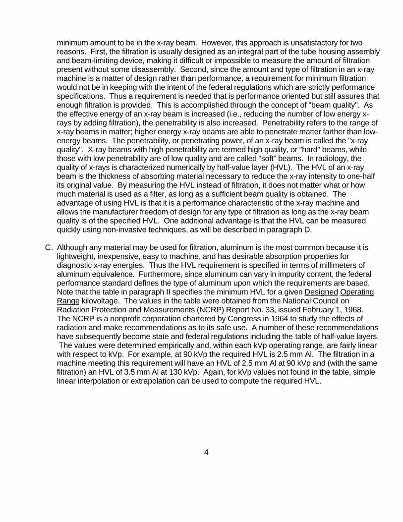
D. Testing for HVL is performed by making successive exposures with increasing thicknesses ofaluminum sheets interposed in the beam. A plot on semilog paper (absorption is exponential)is made with the exposure reading on the y-axis versus the aluminum thickness on the x-axis(see Figure 3).
Figure 3.
The HVL can be determined by finding the 50% value of the initial exposure on the y-axis andthen across to the curve and down to the x-axis for the equivalent aluminum thickness.
V. Summary Guidelines:
A. For systems that provide adjustable filtration, testing will be done with the minimum filtration thatwill still allow an exposure at the selected kVp.
B. The system being tested must be reproducible.
C. For capacitor energy storage equipment, compliance shall be determined with the maximumquantity of charge per exposure.
5
ENTRANCE EXPOSURE RATE (1020.32(d)), 21 CFR Subchapter J
I. Objective of Requirement:
To ensure that unintentional high fluoroscopic entrance exposure rates are not produced.
II. Performance Standard:
A. Requirement for fluoroscopic equipment manufactured before May 19, 1995:
(1) Fluoroscopic equipment which is provided with automatic exposure rate control (AERC)shall not be operable at any combination of tube potential and current which will result in anexposure rate in excess of 10 roentgens per minute (10 R/min) at the point where the centerof the useful beam enters the patient, except: (i) during recording of fluoroscopic images, or(ii) when an optional high level control is provided. When so provided, the equipment shall notbe operable at any combination of tube potential and current which will result in an exposurerate in excess of 5 R/min at the point where the center of the useful beam enters the patient,unless the high level control is activated. Special means of activating the high level controlshall only be operable when continuous manual activation is provided by the operator. Acontinuous signal, audible to the fluoroscopist, shall indicate that the high level control is beingemployed.
(2) Fluoroscopic equipment which is not provided with automatic exposure rate control shallnot be operable at any combination of tube potential and current which will result in anexposure rate in excess of 5 R/min at the point where the center of the useful beam enters thepatient except: (i) during recording of fluoroscopic images, or (ii) when an optional high levelcontrol is activated. Special means of activating the high level controls shall only be operablewhen continuous manual activation is provided by the operator. A continuous signal, audibleto the fluoroscopist, shall indicate that the high level control is being employed.
B. Applicability:
Applies to any fluoroscopic x-ray machine manufactured before May 19, 1995, operated onan adequate power supply as specified by the manufacturer in accordance with therequirements of 1020.30(h)(3).
III. Special Measurement Requirements Incorporated in the Performance Standard:
Compliance shall be determined as follows:
(1) If the source is below the table, the exposure rate shall be measured one centimeter abovethe tabletop or cradle.
(2) If the source is above the table, the exposure rate shall be measured at 30 centimeters abovethe tabletop with the end of the beam-limiting device or spacer positioned as closely aspossible to the point of measurement.
6
(3) In a C-arm type of fluoroscope, the exposure rate shall be measured 30 centimeters from theinput surface of the fluoroscopic imaging assembly.
(4) In a lateral type fluoroscope, the exposure rate shall be measured at a point 15 centimetersfrom the centerline of the table, in the direction of the x-ray source with the end of the beam-limiting device or spacer positioned as close to the point of measurement as possible. If thetabletop is movable, it shall be positioned as close as possible to the lateral x-ray source, withthe end of the beam-limiting device or spacer no closer than 15 centimeters to the centerlineof the table.
IV. Discussion:
A. Fluoroscopy is continuous x-ray exposure at low mA techniques for the purpose of dynamic or"live time" diagnosis. Fluoroscopic examinations can be lengthy, increasing the potential fora high radiation dose to the patient. For this reason, it is imperative that the exposure rateoutput be as low as possible. As the exposure rate is lowered, however, the imagebrightness decreases until eventually it is too dim for diagnostic use. Hence, a compromiseexposure rate is obtained that yields a useable image while not resulting in excessiveexposure to the patient. The National Council on Radiation Protection and Measurementshas determined that most fluoroscopy can be carried out with exposure rates of less than 5R/min (NCRP Report No. 33). There may be an occasional need to go above this level forunusually obese patients or imaging of particularly dense anatomical regions. The exposurerate limits of the standard are based on the NCRP findings. For purposes of the standard, theexposure rate is called "Entrance Exposure Rate" (EER) and is measured at a specific pointaccording to the type of system involved. The word "entrance" refers to the point where the x-ray beam enters the patient. For above table source systems, C-arm fluoroscopes, andlateral fluoroscopes, a standard body thickness of 30 centimeters is assumed, and themeasurement point is established accordingly.
B. Fluoroscopic systems provide several optional means of operation, which necessitatesdifferent entrance exposure rates depending on the mode of operation. The simplest systemsare manual only. Selection of kVp, mA, and time is at the discretion of the fluoroscopist viamanual adjustments. More sophisticated systems can be automatic, meaning that a sensorsamples the radiation output and automatically changes the kVp, mA, or both to maintain aconstant exposure rate. These systems are said to have Automatic Brightness Control (ABC)or Automatic Exposure Rate Control (AERC). Often, systems are designed to provide bothmanual and automatic modes of operation. In addition to these modes, some fluoroscopicsystems have a high-level control (HLC). This is a boosting circuit which when activated bythe fluoroscopist increases the exposure rate significantly. It is used when the normal modeexposure rate is not sufficient to produce a good quality image (i.e. examining a particularlydense region of the body). Both types of systems (both manual and automatic modesavailable in one machine) can have HLC in either mode or both.
C. The rationale for establishment of the EER limits in the standard was not straightforward. Toa large extent, both the manufacturers and fluoroscopists influenced the final published limits(see Tables 1 and 2).
7

TABLE 1
Manual Only Systems
Without a High-Level Control (HLC) 5 R/min
With a High-Level Control (HLC) 5 R/min*
Automatic Only Systems
Without a High-Level Control (HLC) 10 R/min
With a High-Level Control (HLC) 5 R/min*
*Unlimited when the HLC is activated.
TABLE 2
Dual (both manual and automatic modes) Systems
Manual Mode Selected:
Without a High-Level Control (HLC) 10 R/min
With a High-Level Control (HLC) 5 R/min*
Automatic Mode Selected:
Without a High-Level Control (HLC) 10 R/min
With a High-Level Control (HLC) 5 R/min*
*Unlimited when the HLC is activated.
D. As the radiological community generally agrees that most fluoroscopic examinations can beperformed at 5 R/min or less, this became the established upper limit for manual systems andsystems with high-level control (not activated). For those procedures that sometimes requirea higher EER, it was felt that this could be obtained by activating the high-level control. Initialattempts to establish an upper EER limit for the HLC mode proved unproductive. At the time,fluoroscopic systems operating in HLC were producing EER's from 5 R/min to 25 R/min,depending largely on what the purchaser wanted. Whereas some fluoroscopists weresatisfied with the images at lower EER's, others wanted brighter images produced by higherEER's such that no single upper limit value seemed to satisfy all. The argument that use ofHLC represented a special instance, and for a short period of time only, where thefluoroscopist wanted to zero in on a pathology and needed a brightness acceptable to him,had merit from a medical stand point where the benefits could be shown to outweigh the risks.
8
Furthermore, beyond a certain EER (approximately 25 R/min), the image begins to “washout". Therefore, an upper limit is ostensibly established by the performance limitation of the

equipment. Because of the arguments presented in support of allowing flexibility in setting theEER for high-level control at the discretion of the user, it was agreed to not establish an upperlimit, realizing of course, that an upper limit would be achieved by the electronic limitations ofthe machine. Along with this decision, however, was the feeling that the fluoroscopist shouldbe constantly reminded during the entire time that the HLC is activated since high exposurerates would be in use. Therefore, the standard was written to require a continuous audiblesignal and continuous manual activation by the operator during use.
E. Table 1 shows an EER limit for automatic systems that is different than that for manualsystems. Automatic fluoroscopic systems are designed to maintain the desired image at thelowest EER possible during the entire examination. This means that in dynamic studiesinvolving imaging of different density regions of the body, the EER will fluctuate up and downand will not be constant. This is not the case for manual systems, where once the fluoroscopictechniques are set, a constant EER is produced, regardless of imaging requirements. Earlyin the development of the standard, manufacturers and fluoroscopists agreed that the limit of 5R/min imposed on automatic systems would be unrealistic. Since automatic systems operateat the lowest possible EER, it is less than 5 R/min most of the time. Occasionally, certaincomplicated procedures of high density techniques require an EER that "spikes" higher than5 R/min to maintain a proper image throughout the examination. Thus, it was argued that bylimiting the EER to 5 R/min for automatic systems, the greater flexibility would be lost and thesystem would be no more than a sophisticated manual system. This argument was accepted,and a compromise EER limit of 10 R/min was established for automatic systems withoutHLC. For systems with HLC, the consensus was that the EER be limited to 5 R/min, since thecapability for obtaining a higher EER was available through use of the HLC.
F. An exception to the 5 R/min EER applies to dual mode equipment. In Table 2, note that theEER for the manual mode without HLC is 10 R/min, whereas it is 5 R/min for manual onlyequipment.
Manufacturers of dual mode equipment argued that since the electronics controlling the EERlimit was the same for both modes, it would be much more complicated and expensive todesign the circuitry to deliver a different EER in each mode. Thus, it was agreed to raise the5 R/min EER limit to 10 R/min for the manual mode without HLC to match the automatic modewithout HLC.
V. Summary Guidelines:
A. Measurement of EER is usually performed in conjunction with measurement of "primaryprotective barrier" transmission in accordance with 1020.32(a)(2). Care should be taken toassure proper measurement geometry for the type of system being tested.
B. Some systems provide the control buttons for HLC, but it is not connected at the user'srequest. Such systems must be tested for HLC operation before measuring EER since thelimits are different for systems with HLC compared to those without HLC.
9
C. For dual mode equipment, the EER must be measured in both the automatic and manualmode.
D. Many systems, both automatic and manual, do not yield their maximum EER at maximum tubepotential or tube current; therefore, during the test, the kVp and mA should be varied to obtainthe highest EER for comparison to the limits of the standard.

E. For some image-intensified systems with automatic exposure rate control, but with only directmirror viewing (i.e., no television monitor), room light can leak into the system and cause theAERC to suppress the kVp and mA. Therefore, when testing these systems the room lightshould be as low as possible.
10
ENTRANCE EXPOSURE RATE (1020.32(e)), 21 CFR Subchapter J
I. Objective of Requirement:
To ensure that unintentional high fluoroscopic entrance exposure rates are not produced.
II. Performance Standard:
A. Requirement for fluoroscopic equipment manufactured after May 19, 1995:
(1) Fluoroscopic equipment which is provided with automatic exposure rate control (AERC)shall not be operable at any combination of tube potential and current which will result in anexposure rate in excess of 10 roentgens per minute (10 R/min) at the point where the centerof the useful beam enters the patient, except: (i) during recording of fluoroscopic images fromthe image intensifier while in pulsed mode operation, or (ii) when an optional high level control(HLC) is provided. When an optional high level control is provided, the equipment shall not beoperable at any combination of tube potential and current which will result in an exposure ratein excess of 20 R/min at the point where the center of the useful beam enters the patient, whenthe high level control is activated. Special means of activating the high level control shall onlybe operable when continuous manual activation is provided by the operator. A continuoussignal, audible to the fluoroscopist, shall indicate that the high level control is being employed.
(2) Fluoroscopic equipment operable at any combination of tube potential and current whichwill result in an exposure rate in excess of 5 R/min at the point where the center of the usefulbeam enters the patient shall be equipped with AERC. Provision for manual selection oftechnique factors may be provided.
B. Applicability:
Applies to any fluoroscopic x-ray machine manufactured after May 19, 1995, operated on anadequate power supply as specified by the manufacturer in accordance with the requirementsof 1020.30(h)(3).
III. Special Measurement Requirements Incorporated in the Performance Standard:
Compliance shall be determined as follows:
(1) If the source is below the table, the exposure rate shall be measured one centimeter abovethe tabletop or cradle.
(2) If the source is above the table, the exposure rate shall be measured at 30 centimeters abovethe tabletop with the end of the beam-limiting device or spacer positioned as closely aspossible to the point of measurement.
(3) In a C-arm type of fluoroscope, the exposure rate shall be measured 30 centimeters from theinput surface of the fluoroscopic imaging assembly.
11
(4) In a lateral type fluoroscope, the exposure rate shall be measured at a point 15 centimetersfrom the centerline of the table, in the direction of the x-ray source with the end of the beam-limiting device or spacer positioned as close to the point of measurement as possible. If thetabletop is movable, it shall be positioned as close as possible to the lateral x-ray source, withthe end of the beam-limiting device or spacer no closer than 15 centimeters to the centerlineof the table.
IV. Discussion:
The Diagnostic Federal Performance Standard was amended on May 19, 1994, in an attempt tolimit the misuse of the HLC during routine fluoroscopic procedures. The amendments removedthe two tier EER system set the EER to 10 R/min. Because the old requirement limited the EERto 5 R/min in those modes provided with HLC, the user often initiated the HLC to increasebrightness. Such activation increased the EER from 5 R/min to 10, 20, or 30 R/min whenperhaps 8 or 9 R/min would have been sufficient. Because of the way the electronics were setup, higher exposures than necessary were being used and the EER limits were beingcircumvented in compliance with the standard. The amendments attempted to eliminate this loophole and provide a range where the majority of fluoroscopic procedures could operate withoutexcessive exposures. In addition because of reports of some radiation burns, the amendmentsput a limit on the maximum EER while in high level mode of operation. It did not however, put alimit on record mode EER. The amendments also limited any manual only type system to 5R/minor lower. If the unit could operate above this level then it must also have AERC.
12
FIELD LIMITATION AND ALIGNMENT (1020.31(e), (f), (g), 1020.32(b)), 21 CFR Subchapter J
I. Objective of Requirement:
To ensure within acceptable limits that the x-ray field is of appropriate size and aligned withthe image receptor.
II. Performance Standard:
A. Stationary General Purpose Systems:
1. Requirement:
Means shall be provided to align the center of the x-ray field with respect to thecenter of the image receptor within 2 percent of the source-image receptor distance(SID).
Means shall be provided for positive beam limitation (PBL) which will, at the SID forwhich the device is designed, either cause automatic adjustment of the x-ray field inthe plane of the image receptor to the image receptor size within 5 seconds afterinsertion of the image receptor or, if adjustment is accomplished automatically in atime interval greater than 5 seconds, or is manual, will prevent production of x-raysuntil such adjustment is completed. At SID's at which the device is not intended tooperate, the device shall prevent the production of x-rays.
The x-ray field size in the plane of the image receptor, whether automatically ormanually adjusted, shall be such that neither the length nor the width of the x-ray fielddiffers from that of the image receptor by greater than 3 percent of the SID and thatthe sum of the length and width differences without regard to sign be no greater than4 percent of the SID when the equipment indicates that the beam axis isperpendicular to the plane of the image receptor.
The radiographic system shall be capable of operation, at the discretion of theoperator, such that the field size at the image receptor can be adjusted to a sizesmaller than the image receptor. The minimum field size at a distance of 100centimeters shall be equal to or less than 5 by 5 centimeters. Return to PBL shalloccur upon a change in image receptor size or SID.
2. Applicability:
Applies to stationary general purpose radiographic systems except when spot-filmdevices.
13
B. Equipment Using Intraoral Image Receptors:
1. Requirement:
Radiographic equipment designed for use with an intraoral image receptor shall beprovided with means to limit the x-ray beam such that:
(I) If the minimum source-to-skin distance (SSD) is 18 centimeters or more, thex-ray field at the minimum SSD shall be containable in a circle having adiameter of no more than 7 centimeters; and
(II) If the minimum SSD is less than 18 centimeters, the x-ray field at the minimumSSD shall be containable in a circle having a diameter of no more than 6centimeters.
2. Applicability:
Applies to radiographic equipment designed for use with an intraoral imagereceptor.
C. X-ray Systems Designed for One Image Receptor Size:
1. Requirement:
Radiographic equipment designed for only one image receptor size at a fixed SIDshall be provided with means to limit the field at the plane of the image receptor todimensions no greater than those of the image receptor, and to align the center ofthe x-ray field with the center of the image receptor to within 2 percent of the SID orshall be provided with means to both size and align the x-ray field such that the x-rayfield at the plane of the image receptor does not extend beyond any edge of theimage receptor.
2. Applicability:
Applies to radiographic equipment designed for one image receptor size at a fixedSID.
D. Mammography:
1. Requirement:
Radiographic systems designed for mammography shall be provided with means tolimit the useful beam such that the x-ray field at the plane of the image receptor doesnot extend beyond any edge of the image receptor at any designated SID except theedge of the image receptor designed to be adjacent to the chest wall where the x-rayfield may not extend beyond this edge by more than 2 percent of the SID.
142. Applicability:
Applies to mammography equipment manufactured before September 30, 1999.
For mammography equipment manufactured after September 30, 1999, the x-rayfield may not extend beyond any edge of the image receptor by more than 2 percentof the SID.
E. Other X-ray Systems:
1. Requirement:
Radiographic systems not specifically covered in paragraphs A, B, C, and D andsystems designed for use with extraoral image receptors and when used with anextraoral image receptor, shall be provided with means to limit the x-ray field in theplane of the image receptor so that such field does not exceed each dimension ofthe image receptor by more than 2 percent of the SID, when the axis of the x-raybeam is perpendicular to the plane of the image receptor. In addition, means shallbe provided to align the center of the x-ray field with the center of the image receptorto within 2 percent of the SID, or means shall be provided to both size and align thex-ray field such that the x-ray field at the plane of the image receptor does not extendbeyond any edge of the image receptor.
2. Applicability:
Applies to radiographic systems not covered in the previous paragraphs and arealso designed for use with extraoral image receptors.
F. Spot-Film Devices:
1. Requirement:
Means shall be provided between the source and the patient for adjustment of the x-ray field size in the plane of the film to the size of that portion of the film that has beenselected on the spot-film selector. Such adjustment shall be accomplishedautomatically when the x-ray field size in the plane of the film is greater than theselected portion of the film. If the field size is less than the size of the selectedportion of the film, the means for adjustment of the field size shall be only at theoperator's option. The total misalignment of the edges of the x-ray field with therespective edges of the selected portion of the image receptor along the length orwidth dimensions of the x-ray field in the plane of the image receptor shall not exceed3 percent of the SID when adjusted for full coverage of the selected portion of theimage receptor. The sum without regard to sign of the misalignment along any twoorthogonal dimensions shall not exceed 4 percent of the SID. It shall be possible toadjust the x-ray field size in the plane of the film to a size smaller than the selectedportion of the film. The minimum field size, at the greatest SID, shall be equal to orless than 5 by 5 centimeters. The center of the x-ray field in the plane of the film shallbe aligned with the center of the selected portion of the film to within 2 percent of theSID.
15

2. Applicability:
Applies to spot-film devices, except when the spot-film device is provided for usewith a radiation therapy simulation system.
G. Nonimage-intensified Fluoroscopic Systems:
1. Requirement:
The x-ray field produced by nonimage-intensified fluoroscopic equipment shall notextend beyond the entire visible area of the image receptor. Means shall beprovided for stepless adjustment of the field size. The minimum field size at thegreatest SID shall be equal to or less than 5 by 5 centimeters.
2. Applicability:
Applies to fluoroscopic x-ray systems that do not have an image intensifier.
H. Image-intensified Fluoroscopic Systems:
1. Requirement:
For image-intensified fluoroscopic equipment other than radiation therapy simulationsystems, neither the length nor the width of the x-ray field in the plane of the imagereceptor shall exceed that of the visible area of the image receptor by more than 3percent of the SID. The sum of the excess length and the excess width shall be nogreater than 4 percent of the SID. For rectangular x-ray fields used with circularimage receptors, the error alignment shall be determined along the length and widthdimensions of the x-ray field which pass through the center of the visible area of theimage receptor. Means shall be provided to permit further limitation of the field. Beam-limiting devices manufactured after May 22, 1979, and incorporated inequipment with a variable SID and/or a visible area of greater than 300 squarecentimeters shall be provided with means for stepless adjustment of the x-ray field. Equipment with a fixed SID and a visible area of 300 square centimeters or lessshall be provided with either stepless adjustment of the x-ray field or with means tofurther limit the x-ray field size at the plane of the image receptor to 125 square centi-meters or less. Stepless adjustment shall, at the greatest SID, provide continuousfield sizes from the maximum obtainable to a field size of 5 by 5 centimeters or less.
2. Applicability:
Applies to fluoroscopic systems that use an image intensifier except for radiationtherapy simulation systems.
16

III. Special Measurement Requirements Incorporated in the Performance Standard:
A. Stationary General Purpose Systems:
Compliance measurements will be made at discrete SID's and image receptor dimensionsin common clinical use (such as SID's of 36, 40, 48, and 72 inches and nominal imagereceptor dimensions of 5, 7, 8, 9, 10, 11, 12, 14, and 72 inches) or at any other specificdimensions at which the beam limiting device or its associated diagnostic x-ray system isuniquely designed to operate.
B. Equipment Using Intraoral Image Receptors:
None
C. X-ray Systems Designed for One Image Receptor Size:
None
D. Mammography:
None
E. Other X-ray Systems:
Compliance will be determined with the axis of the x-ray beam perpendicular to the plane ofthe image receptor.
F. Spot-film Devices:
For spot-film devices manufactured after February 25, 1978, if the angle between the planeof the image receptor and beam axis is variable, means shall be provided to indicate whenthe axis of the x-ray beam is perpendicular to the plane of the image receptor, andcompliance shall be determined with the beam axis indicated to be perpendicular to theplane of the image receptor.
G. Nonimage-intensified Fluoroscopic Systems:
For equipment manufactured after February 25, 1978, when the angle between the imagereceptor and the beam axis of the x-ray beam is variable, means shall be provided toindicate when the axis of the x-ray beam is perpendicular to the plane of the image receptor. Compliance shall be determined with the beam axis indicated to be perpendicular to theplane of the image receptor.
17H. Image-Intensified Fluoroscopic Systems:
For equipment manufactured after February 25, 1978, when the angle between the imagereceptor and beam axis is variable, means shall be provided to indicate when the axis ofthe x-ray beam is perpendicular to the plane of the image receptor. Compliance shall bedetermined with the beam axis indicated to be perpendicular to the plane of the imagereceptor.
IV. Discussion:
A. Equally important to assuring that the x-ray beam passes through the region of thepatient's body of clinical interest, is that the x-ray beam also aligns with the imagereceptor. As discussed in the “requirement" sections of paragraph II, there are avariety of diagnostic x-ray systems, each with its own alignment criteria. However, thenet result is an attempt to assure that the x-ray beam not only strikes the imagereceptor, but is also (within allowable tolerances) contained within it.
B. The benefits of confining the x-ray beam within the image receptor are twofold. First,any part of the beam that “spills" over the image receptor is useless and onlycontributes to increased patient exposure. Eliminating this excess helps to lower theradiation dose received by the patient. Second, collimating the beam reduces scatterradiation resulting in a radiograph of improved clarity. Usually the radiographer willchoose an image receptor that is just large enough to cover the area of clinical interest,and while the x-ray field can be no larger than the image receptor, it normally should notbe smaller either since loss of diagnostic information or key landmarks may occur fromunexpected "cone cutting" or collimation. Sometimes it is desirable to be able tocollimate the x-ray field smaller than the image receptor for exceptional clarity. Thus theprovisions of the standard for certain systems allow further reduction of the x-ray field atthe discretion of the radiographer.
C. Since each x-ray system is unique in its performance, the x-ray field/image receptoralignment problems are also unique. Accordingly, the requirements in the standard aretailored to each individual system type. Because stationary general-purpose systemsuse a variety of image receptor sizes at varying SID's, it cannot be guaranteed thatproper collimation will always be obtained if left to the discretion of the operator. Hence, a positive means for assuring collimation is required. This requirement is metby positive beam limitation (PBL). PBL provides collimation by either automaticallyadjusting the size of the x-ray beam to the size of the image receptor (automatic PBL)or by preventing the exposure until the size of the x-ray beam is adjusted manually tothe size of the image receptor (semiautomatic PBL). Additionally, PBL must allow forreduction of the x-ray field to a size smaller than the image receptor, since it issometimes desirable or necessary to reduce the field for improved image quality. Under certain conditions, it is agreed that PBL is either not practical or possible.
18

For example, some radiographic procedures require that the image receptor (filmcassette) be placed directly in contact with the patient (extremities imaging) and not inthe sensing tray. When this occurs, there is no way for the system to sense thecassette size, thus PBL is impossible to achieve. Under these circumstances, thestandard allows for the "bypass" of PBL. Bypass means that the system canautomatically disengage the PBL. However, the standard requires that the systemreturn to PBL operation automatically when PBL conditions are once againestablished. Other conditions of bypass are given in 1020.31 (g)(2)(i-v).
D. Since the specific x-ray field/image receptor alignment requirements of each type ofsystem are explained in paragraph II of this part, it is suggested that they be studiedindividually for a better understanding of the unique provisions. While reviewing therequirements, it should be noted that two distinct methods of achieving alignment arewritten into the standard, and depending on the system, one or the other applies. Thefirst method is a misalignment requirement where the misalignment of the respectiveedges of the x-ray field and image receptor cannot exceed a certain percentage of theSID. The second method is a "size and centers" requirement, which provides for the x-ray field to be the same size as the image receptor and the centers of each to bealigned. Each method assures congruence of the x-ray field and image receptor withincertain tolerances as related to the SID.
V. Summary Guidelines:
A. Since each type of system has unique requirements for x-ray field/image receptoralignment, care must be used when testing the system to assure that the appropriatemeasurements are made.
B. For those systems that require size comparison of the x-ray field and image receptor,the centers alignment must also be determined.
C. For PBL systems, the alignment should be checked at more than one image receptorsize and SID to determine if the system is functioning throughout the PBL range.
D. For spot-film devices and both image-intensified and nonimage-intensifiedfluoroscopic systems manufactured after February 25, 1978, indication ofperpendicularity of the x-ray beam axis with the image receptor is required. Testing ofalignment is to be performed with the x-ray beam axis indicated to be perpendicular tothe plane of the image receptor.
E. If using light field measurements to determine x-ray field/image receptor alignment,correction factors for the difference in light field/ x-ray field size and alignment must becomputed and applied in the final compliance determination.
F. When using x-ray film for determining x-ray field/image receptor alignment, care mustbe exercised in discerning the x-ray field edge at the cathode side since the penumbraat this edge can be quite large and the edge not clearly defined.
19
ILLUMINANCE (1020.31(d)(2)(ii)) 21 CFR Subchapter J
I. Objective of Requirement:
To ensure that the light localizer provides enough light to define the x-ray field and iseasily seen under ambient lighting conditions.
II. Performance Standard:
A. Requirement:
When a light localizer is used to define the x-ray field, it shall provide an averageillumination of not less than 160 lux (15 foot-candles) at 100 centimeters or at themaximum SID, whichever is less.
B. Applicability:
Applies to any diagnostic radiographic x-ray system employing a light localizer forvisual definition of the x-ray field.
III. Special Measurement Requirements Incorporated in the Performance Standard:
The average illumination shall be based upon measurements made in the approximatecenter of each quadrant of the light field.
IV. Discussion:
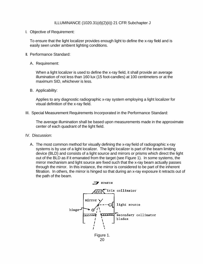
A. The most common method for visually defining the x-ray field of radiographic x-raysystems is by use of a light localizer. The light localizer is part of the beam limitingdevice (BLD) and consists of a light source and mirrors or prisms which direct the lightout of the BLD as if it emanated from the target (see Figure 1). In some systems, themirror mechanism and light source are fixed such that the x-ray beam actually passesthrough the mirror. In this instance, the mirror is considered to be part of the inherentfiltration. In others, the mirror is hinged so that during an x-ray exposure it retracts out ofthe path of the beam.
Figure 1.20

B. Since the radiographer often relies solely on the light localizer to position the patient, itis extremely important that there is enough light produced to see the light field clearlyeven on low contrast surfaces such as dark clothing. Additionally, the light field must beof sufficient illumination to be seen easily in ambient room lighting. The requirement of160 lux at 100 centimeters or maximum SID represents a reasonable compromise toachieve the above performance characteristics while still allowing for practical designby the manufacturer when considering size of the light source and heat capacity.
C. It is important that the light field be uniform over the entire illuminated area including theedges to facilitate proper patient positioning. For this reason, it is more realistic to testfor illumination at several different points of the field rather than at just one, such as thecenter, where oftentimes the illuminance is greatest. Thus, the standard provides fortesting of four points, one in each quadrant, with calculation of the average illumination.
V. Summary Guidelines:
A. When testing for illuminance, four measuring points are to be used, one in eachquadrant of the light field.
B. The ambient room light illuminance must be subtracted from the light field illuminance ateach measurement point. Avoid moving the detector between measurements of thelight field illuminance and ambient room light illuminance.
C. When placing the detector in the light field, avoid any dark bands such as those causedby cross-hair images.
21

LINEARITY (1020.31(c)), 21 CFR Subchapter J
I. Objective of Requirement:
To ensure within acceptable limits that an x-ray machine can deliver a one-to-oneproportionate exposure when increasing or decreasing the tube current (mA).
II. Performance Standard:
A. Requirement:
The average ratios of exposure to the indicated milliampere-seconds product(mR/mAs) obtained at any two consecutive tube current settings shall not differ by morethan 0.10 times their sum. That is:
X̄ 1 − X̄ 2 ≤ 0.10(X̄ 1 + X̄ 2)
where X̄ 1 and ̄X 2 are the average mR/mAs values obtained at each of two consecutivetube current settings.
B. Applicability:
For radiographic controls manufactured before May 1994, that have independent tubecurrent settings or if manufactured after May 1994 have independent tube currentselection or mAs selectable techniques. The x-ray unit must be operated on a powersupply as specified in accordance with the requirements of 1020.30(h)(3) for any fixedx-ray tube potential (kVp) within the range of 40 to 100 percent of the maximum ratedkVp.
III. Special Measurement Requirements Incorporated in the Performance Standard:
Determination of compliance will be based on 10 exposures at each of twoconsecutive x-ray tube current settings made within one hour. The percent line-voltage regulation shall be determined for each measurement. All values forpercent line-voltage regulation at any one combination of technique factors shall bewithin +/- 1 of the mean value for all measurements at these technique factors. Where tube current selection is continuous, X0.5 and X2 shall be obtained atcurrent settings differing by no greater than a factor of 2.
22
IV. Discussion:
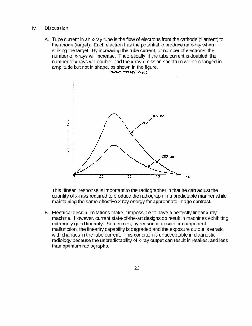
A. Tube current in an x-ray tube is the flow of electrons from the cathode (filament) tothe anode (target). Each electron has the potential to produce an x-ray whenstriking the target. By increasing the tube current, or number of electrons, thenumber of x-rays will increase. Theoretically, if the tube current is doubled, thenumber of x-rays will double, and the x-ray emission spectrum will be changed inamplitude but not in shape, as shown in the figure.
This "linear" response is important to the radiographer in that he can adjust thequantity of x-rays required to produce the radiograph in a predictable manner whilemaintaining the same effective x-ray energy for appropriate image contrast.
B. Electrical design limitations make it impossible to have a perfectly linear x-raymachine. However, current state-of-the-art designs do result in machines exhibitingextremely good linearity. Sometimes, by reason of design or componentmalfunction, the linearity capability is degraded and the exposure output is erraticwith changes in the tube current. This condition is unacceptable in diagnosticradiology because the unpredictability of x-ray output can result in retakes, and lessthan optimum radiographs.
23
For this reason, the federal performance standard addresses linearity and imposes amaximum limit of variation when changing from one mA setting to another. It isimportant to note that since the x-ray tube current and high voltage are supplied from astep-up transformer, a change in one affects the other according to the transformer law. This law basically states that tube current and tube potential are inversely proportionalto each other. Thus when the tube current is increased, the high voltage drops. Thisdecrease in high voltage results in lower energy x-rays being produced such that moreof them are absorbed in the target, glass envelope, filters and other components of thetube housing. Hence, the x-ray output is altered to the extent that it is no longer linearwith changes in tube current unless the high voltage is adjusted to the same value ateach mA setting. Most x-ray systems employ a compensating circuit that automaticallyadjusts the kVp to the original selected value whenever the mA is changed. Someolder systems, however, do not have these circuits and must be compensated manuallyto assure optimum linearity. Systems requiring manual compensation can berecognized by the kVp selector. The control typically contains a kVp meter and majorand minor kVp knobs for increasing or decreasing the kVp through a continuous range. Thus any deviation in kVp can be compensated back to the originally selected value byadjusting the major and/or minor kVp knobs. It is extremely important to perform thiscompensation because small changes in kVp can result in very large changes inexposure. For example, whereas a 5% change in mA results in only a 5% change inexposure, a 5% change in kVp results in an approximately 15% change!
C. As discussed in the preceding paragraph, design limitations preclude perfect linearityso that some variation is almost always present. The amount of this variation becomesmore drastic the further apart the mA values are from each other. In actual practice,however, the radiographer, in seeking to adjust the tube current to an appropriate valuefor imaging, will rarely jump from one extreme to another but, rather, select consecutivesettings to obtain the proper exposure. Hence it is more realistic to test x-ray systemsunder actual use conditions. Therefore, the federal performance standard provides thattesting for linearity will be done for consecutive tube current settings. Because somesystems do not provide discrete mA stations but continuous selection only, thestandard (following the same philosophy for actual use) requires testing these systemsat mA settings not varying from each other by more than a factor of 2.
D. Ideally, the filament of an x-ray tube should be infinitely small so that the cross section ofthe electron stream will be as small as possible. This would result in a small focal spotthat is extremely desirable in diagnostic radiography. Unfortunately, the tremendousheat buildup in the filament and the target during x-ray production, and the number ofavailable electrons required to be released from the filament limit the minimum size. Most general-purpose diagnostic x-ray systems actually have two filaments of differentsizes. At low mA settings a small filament is used since it gives a small focal spot butis still able to deliver the desired tube
24
current while withstanding the heat stress. At larger mA settings the x-ray systemswitches to a large filament in order to compensate for the increased load. Sometimes, due to geometric effects and other physical phenomena, the exposureoutput can be nonlinear when the adjacent mA settings selected involve two differentfilaments (or focal spots). Appropriately designed systems, however, eliminate thisproblem. Thus, there is no reason for the x-ray machine to be unable to maintainlinearity within the limits specified in the standard. The only qualifications made were inthe amendments of May 1995. Because very small focal spots may be used on somespecial type equipment for high resolution, the regulations prohibit the testing betweenfocal spot sizes of less than 0.45 mm and those greater than 0.45 mm. No qualificationis made when selecting consecutive mA settings involving different focal spot sizeswithin the same range specified above, and the test for linearity is valid for thoseconditions as well.
E. All x-ray machines allow for certain technique selections, the most common being kVp,mA, and time. Usually, the more general in purpose, the more independent techniqueselections are available. For those systems with limited technique selection, thecommon design is to combine mA and time into one selector (mAs), to providephototiming only, or to fix the mA. These systems cannot be tested for linearity sinceother electrical parameters are integrated with mA and cannot be separated such thatthe test evaluates changes in tube current only, to which the requirement in the standardapplies. No attempt should be made to evaluate performance of these type systemswith respect to the limits of the linearity requirement.
V. Summary Guidelines:
A. Testing is performed only on radiographic systems that provide a choice of x-ray tubecurrent settings.
B. A change in tube current may cause a shift in kVp. The kVp must be adjusted back tothe original setting if manual compensation is available.
C. Testing is performed between any two consecutive settings for discrete stations, orbetween two settings not differing by more than a factor of 2 for continuous selection.
D. Exposure values should be approximately doubled when the tube current is doubled orhalved when the tube current is halved.
25
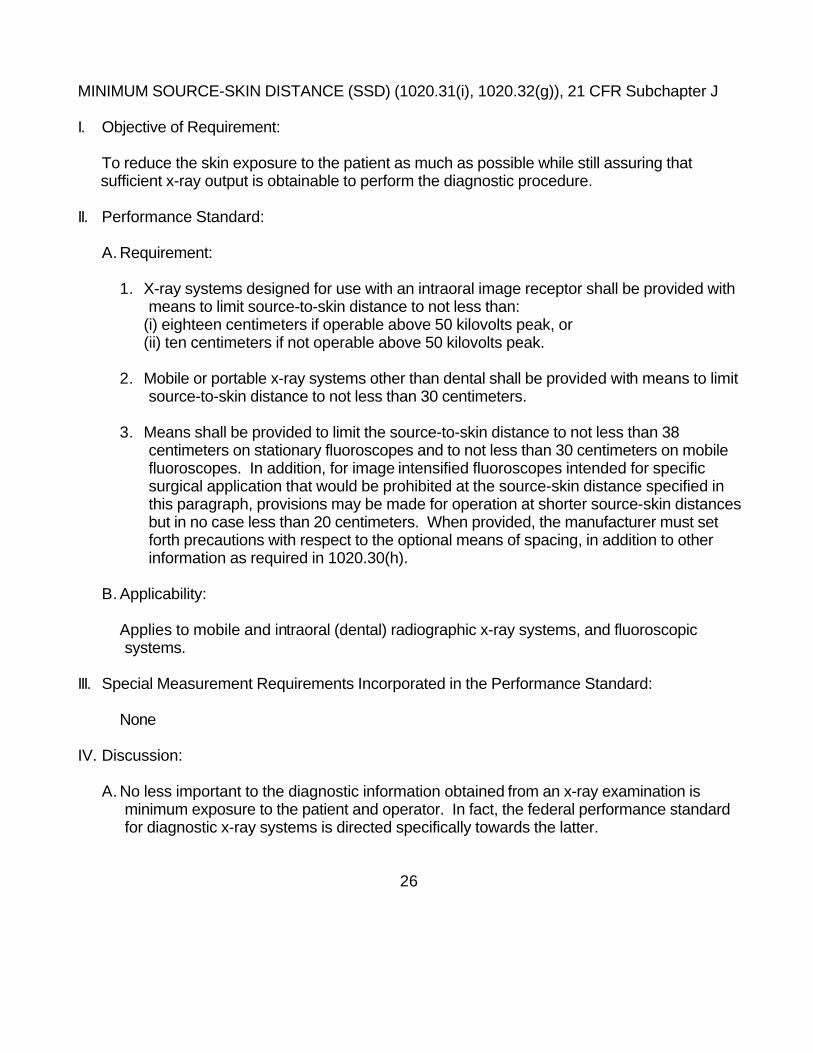
MINIMUM SOURCE-SKIN DISTANCE (SSD) (1020.31(i), 1020.32(g)), 21 CFR Subchapter J
I. Objective of Requirement:
To reduce the skin exposure to the patient as much as possible while still assuring thatsufficient x-ray output is obtainable to perform the diagnostic procedure.
II. Performance Standard:
A. Requirement:
1. X-ray systems designed for use with an intraoral image receptor shall be provided withmeans to limit source-to-skin distance to not less than:
(i) eighteen centimeters if operable above 50 kilovolts peak, or(ii) ten centimeters if not operable above 50 kilovolts peak.
2. Mobile or portable x-ray systems other than dental shall be provided with means to limitsource-to-skin distance to not less than 30 centimeters.
3. Means shall be provided to limit the source-to-skin distance to not less than 38centimeters on stationary fluoroscopes and to not less than 30 centimeters on mobilefluoroscopes. In addition, for image intensified fluoroscopes intended for specificsurgical application that would be prohibited at the source-skin distance specified inthis paragraph, provisions may be made for operation at shorter source-skin distancesbut in no case less than 20 centimeters. When provided, the manufacturer must setforth precautions with respect to the optional means of spacing, in addition to otherinformation as required in 1020.30(h).
B. Applicability:
Applies to mobile and intraoral (dental) radiographic x-ray systems, and fluoroscopicsystems.
III. Special Measurement Requirements Incorporated in the Performance Standard:
None
IV. Discussion:
A. No less important to the diagnostic information obtained from an x-ray examination isminimum exposure to the patient and operator. In fact, the federal performance standardfor diagnostic x-ray systems is directed specifically towards the latter.
26
Many design features provide for both patient and operator protection such as propercollimation and tube housing shielding. Other design features provide for reduction ofpatient exposure only. The minimum "source-to-skin distance" (SSD) is such a feature.
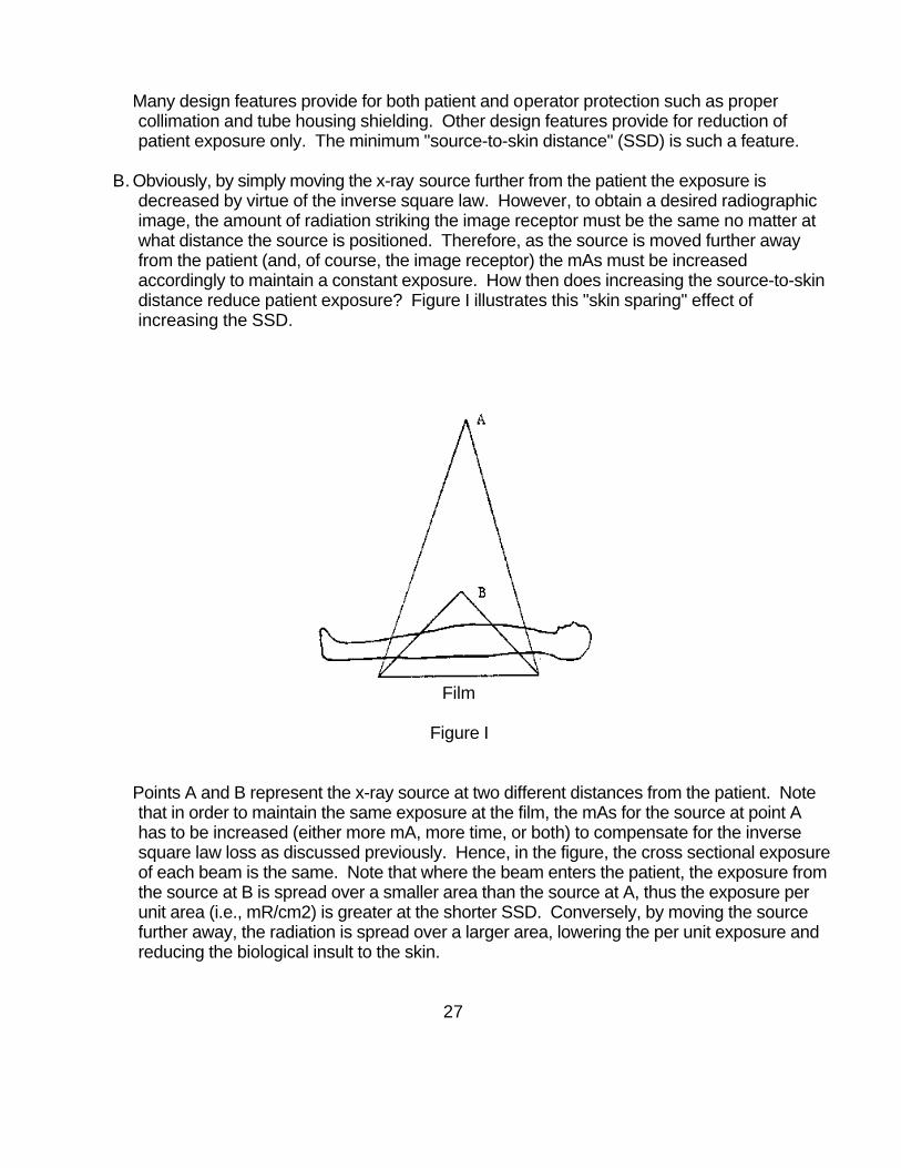
B. Obviously, by simply moving the x-ray source further from the patient the exposure isdecreased by virtue of the inverse square law. However, to obtain a desired radiographicimage, the amount of radiation striking the image receptor must be the same no matter atwhat distance the source is positioned. Therefore, as the source is moved further awayfrom the patient (and, of course, the image receptor) the mAs must be increasedaccordingly to maintain a constant exposure. How then does increasing the source-to-skindistance reduce patient exposure? Figure I illustrates this "skin sparing" effect ofincreasing the SSD.
Film
Figure I
Points A and B represent the x-ray source at two different distances from the patient. Notethat in order to maintain the same exposure at the film, the mAs for the source at point Ahas to be increased (either more mA, more time, or both) to compensate for the inversesquare law loss as discussed previously. Hence, in the figure, the cross sectional exposureof each beam is the same. Note that where the beam enters the patient, the exposure fromthe source at B is spread over a smaller area than the source at A, thus the exposure perunit area (i.e., mR/cm2) is greater at the shorter SSD. Conversely, by moving the sourcefurther away, the radiation is spread over a larger area, lowering the per unit exposure andreducing the biological insult to the skin.
27
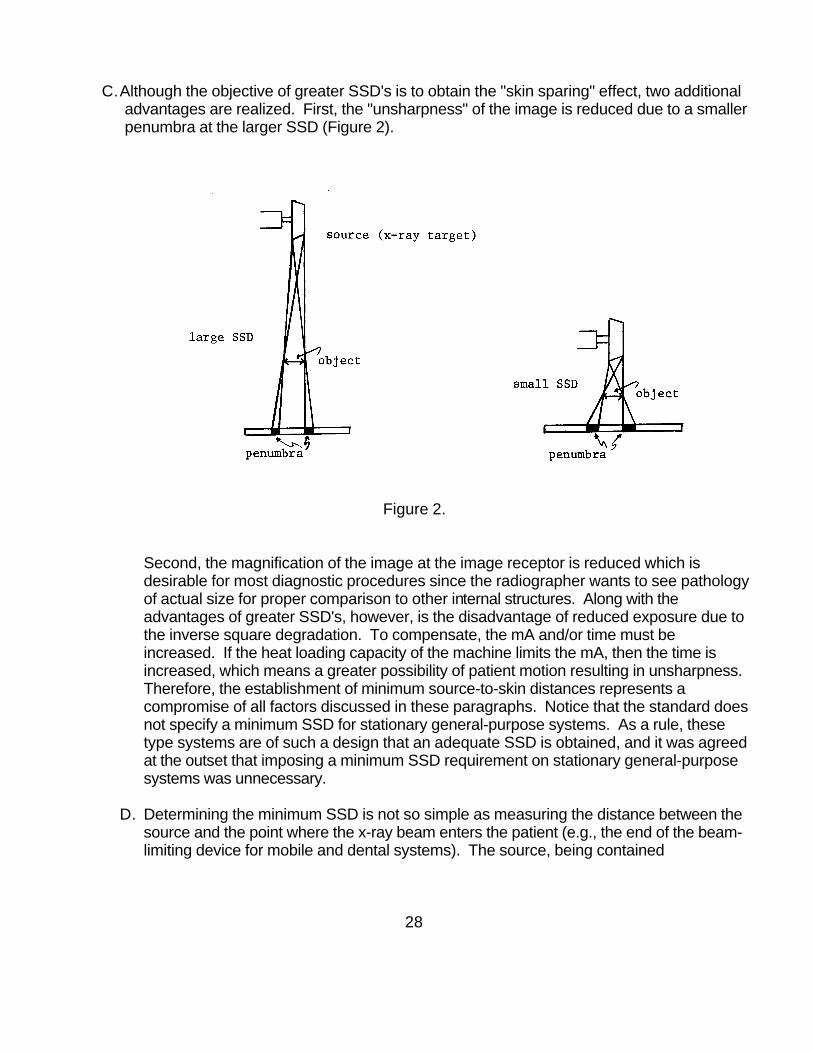
C.Although the objective of greater SSD's is to obtain the "skin sparing" effect, two additionaladvantages are realized. First, the "unsharpness" of the image is reduced due to a smallerpenumbra at the larger SSD (Figure 2).
Figure 2.
Second, the magnification of the image at the image receptor is reduced which isdesirable for most diagnostic procedures since the radiographer wants to see pathologyof actual size for proper comparison to other internal structures. Along with theadvantages of greater SSD's, however, is the disadvantage of reduced exposure due tothe inverse square degradation. To compensate, the mA and/or time must beincreased. If the heat loading capacity of the machine limits the mA, then the time isincreased, which means a greater possibility of patient motion resulting in unsharpness. Therefore, the establishment of minimum source-to-skin distances represents acompromise of all factors discussed in these paragraphs. Notice that the standard doesnot specify a minimum SSD for stationary general-purpose systems. As a rule, thesetype systems are of such a design that an adequate SSD is obtained, and it was agreedat the outset that imposing a minimum SSD requirement on stationary general-purposesystems was unnecessary.
D. Determining the minimum SSD is not so simple as measuring the distance between thesource and the point where the x-ray beam enters the patient (e.g., the end of the beam-limiting device for mobile and dental systems). The source, being contained
28

within the tube housing assembly, is inaccessible, thus the measurement of SSD issomewhat indirect by use of triangulation as shown in Figure 3.
Figure 3.
The test setup involves placing an object of known dimension in the path of the beam,which produces an image of measurable dimensions at some known distance (d2) fromthe object. By use of the similar triangles equation, the unknown distance (d1) can becalculated as follows:
d1 =
d1 + d2
Object dimension Image dimension
or
d1 = d2 x Object dimension
Image dimension - Object dimension
Once the distance d1 is obtained, the minimum SSD can be determined, asall other measurements can be made directly (i.e. distance from object to tip of BLD).
IV. Summary Guidelines:
A. The type of system to be tested dictates the measurement geometry. Care must beexercised to use the appropriate test setup.
B. As can be seen in Figure 3, the "object" must be positioned in the beam such that itis fully covered by the beam, and the image receptor is large enough to contain theimage produced.
29
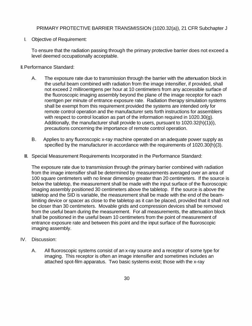
PRIMARY PROTECTIVE BARRIER TRANSMISSION (1020.32(a)), 21 CFR Subchapter J
I. Objective of Requirement:
To ensure that the radiation passing through the primary protective barrier does not exceed alevel deemed occupationally acceptable.
II.Performance Standard:
A. The exposure rate due to transmission through the barrier with the attenuation block inthe useful beam combined with radiation from the image intensifier, if provided, shallnot exceed 2 milliroentgens per hour at 10 centimeters from any accessible surface ofthe fluoroscopic imaging assembly beyond the plane of the image receptor for eachroentgen per minute of entrance exposure rate. Radiation therapy simulation systemsshall be exempt from this requirement provided the systems are intended only forremote control operation and the manufacturer sets forth instructions for assemblerswith respect to control location as part of the information required in 1020.30(g).Additionally, the manufacturer shall provide to users, pursuant to 1020.32(h)(1)(i),precautions concerning the importance of remote control operation.
B. Applies to any fluoroscopic x-ray machine operated on an adequate power supply asspecified by the manufacturer in accordance with the requirements of 1020.30(h)(3).
III. Special Measurement Requirements Incorporated in the Performance Standard:
The exposure rate due to transmission through the primary barrier combined with radiationfrom the image intensifier shall be determined by measurements averaged over an area of100 square centimeters with no linear dimension greater than 20 centimeters. If the source isbelow the tabletop, the measurement shall be made with the input surface of the fluoroscopicimaging assembly positioned 30 centimeters above the tabletop. If the source is above thetabletop and the SID is variable, the measurement shall be made with the end of the beam-limiting device or spacer as close to the tabletop as it can be placed, provided that it shall notbe closer than 30 centimeters. Movable grids and compression devices shall be removedfrom the useful beam during the measurement. For all measurements, the attenuation blockshall be positioned in the useful beam 10 centimeters from the point of measurement ofentrance exposure rate and between this point and the input surface of the fluoroscopicimaging assembly.
IV. Discussion:
A. All fluoroscopic systems consist of an x-ray source and a receptor of some type forimaging. This receptor is often an image intensifier and sometimes includes anattached spot-film apparatus. Two basic systems exist; those with the x-ray
30

source below the table with the imaging system above, and the others with the x-ray sourceabove the table and the imaging system beneath. The imaging system serves twopurposes. One is to provide the imaging function, while the other is to act as a barrier tothe useful beam. Thus the imaging system is considered to be a "primary protectivebarrier" (PPB) as defined in 1020.30 (b), and for fluoroscopic systems is designed tointercept the entire useful beam.
B. Fluoroscopists typically work close to the patient during the fluoroscopic exam, often withpart of their body adjacent to or in contact with the imaging system or table. Therefore, ifany part of the useful beam extends beyond the edges of the PPB, the fluoroscopist couldbe exposed directly to the beam. Additionally, any radiation transmitted through the barriervia poorly fitted joints or improperly shielded spots can also put the fluoroscopist at risk. The performance standard requires that the primary protective barrier intercepts the entireuseful beam and that the transmitted radiation through the barrier not exceed 2 mR/hr pereach R/min of entrance exposure rate and measured as illustrated in Figures 1 and 2.
31

The attenuation block simulates a patient of average size for purposes of duplicating thesame scattering geometry as obtained during actual fluoroscopic examinations. Note thatthe maximum allowable transmission limit in the Standard is not one constant value, butdepends on the entrance exposure rate. Therefore, the PPB transmission must bemeasured while also measuring the EER as illustrated in the figures. The value of 2 mR/hrfor each R/min of EER has been established as an occupationally acceptable level and therequirement can be met quite easily through appropriate design and assembly.
C. Two additional qualifications for measuring compliance are contained in the provisions ofthe standard. First, the requirement specifies that the measurement for PPB transmissionbe averaged over 100 square centimeters with no linear dimension greater than 20centimeters. Care must be exercised to use an instrument with appropriate dimensions ofthe sensitive area of the detector or with the necessary correction factors available tocalculate the actual exposure rate. Second, some image intensifiers emit radiation duringoperation due to the type of electronic components employed. The PPB transmission limitof 2 mR/hr for each R/min of entrance exposure rate includes this image intensifieremission.
V. Summary Guidelines:
A. The type of system to be tested dictates the measurement geometry. Care must beexercised to use the appropriate test setup.
B. Since radiation detection instruments exhibit a finite response time, scanning of theprimary protective barrier must be slow enough to allow the instrument to react. Particularattention should be paid to suspect areas such as joints and bolts.
C. The absolute allowable transmission rate is dependent on the entrance exposure rate. Thus, the EER must be measured simultaneously with measurement of the primaryprotective barrier transmission.
D. For undertable source systems, in which there is no spot-film device, the primary protectivebarrier is the image intensifier housing. In these cases, measurement of barriertransmission will be significantly biased by radiation scattered from the attenuation block. Therefore, while scanning with a radiation detection instrument or quantitatively measuringwith an ion chamber, a lead sheet should be positioned parallel to the tabletop at the planeof the image intensifier input phosphor and positioned to shield the chamber from allradiation except that transmitted through the primary barrier.
E. If using an integrating instrument rather than a rate meter to determine the primaryprotective barrier transmission, any useful reading should be at least 0.05 mR or greater.
32

REPRODUCIBILITY (1020.31(b)), 21 CFR Subchapter J
I. Objective of Requirement:
To ensure within acceptable limits that for a given set of technique factors, an x-ray machinecan deliver the same exposure each time.
II. Performance Standard:
A. Requirement:
The estimated coefficient of variation of radiation exposures shall be no greater than 0.05for any specific combination of technique factors. "Coefficient of Variation" is defined asthe ratio of the standard deviation to the mean value of a population of observations. It isestimated using the following equation:
C SX X
X X nii
n
= = − −=∑1
11
21 2( ( ) / ( )) /
where
S = estimated standard deviation of the population
X = mean value of observations in sample
iX = ith observation sampled
n = number of observations sampled
B. Applicability:
Applies to any radiographic x-ray machine operated on an adequate power supply asspecified by the manufacturer in accordance with the requirements of 1020.30(h)(3).
III. Special Measurement Requirements Incorporated in the Performance Standard:
Determination of compliance shall be based on 10 consecutive measurements takenwithin a time period of 1 hour. Equipment manufactured after September 5, 1978 shall besubject to the additional requirement that all variable controls for technique factors shall beadjusted to alternate settings and reset to the test settings after each measurement. Thepercent line-voltage regulation shall be determined for each measurement. All values forpercent line-voltage regulation shall be within ±1 of the
33
mean value for all measurements. For equipment having automatic exposure controls,compliance shall be determined with a sufficient thickness of attenuating material in theuseful beam such that the technique factors can be adjusted to provide individualexposures of a minimum of 12 pulses on field emission equipment rated for pulsedoperation or no less than one-tenth second per exposure on all other equipment.
IV. Discussion:
A. The production of a diagnostic radiograph of acceptable quality depends on manyfactors. Film composition, processing techniques, and x-ray machine performance arejust a few that affect the final image produced on the radiographic film. Of these,machine performance plays a most important role, because a small change inradiographic technique factors such as kVp or mA can greatly affect the image. Thus,for a given set of technique factor settings, it is desirable that the exposure be thesame each time because the radiographer is depending on a certain radiographicoutcome from the techniques he is using. Any unexpected deviation could result in lessthan optimum diagnostic information or possibly a need to retake the radiograph.
B. The ultimate x-ray output is dependent on many electronic circuits and componentsfunctioning together to provide the desired kVp, mA, and time. Because of smalltransients existing in any circuit operation, along with other influential factors such astarget and filament heating effects, the exposure is hardly ever the same for eachinitiation, but tends to fluctuate within a certain range. This fluctuation is tolerable aslong as the variation does not cause a discernable difference in image quality. However, if the machine is not designed carefully or malfunctions, the fluctuation inexposure can be so drastic as to produce radiographs of unexpected and poor orunusable quality. Hence the reproducibility requirement, while allowing for a smallfluctuation, limits it to a reasonable and obtainable range to assure consistency inimage quality.
C. In actual day-to-day use the x-ray machine technique factors are constantly beingchanged from one value to another for different imaging procedures. The machineshould, however, be able to maintain reproducibility under these conditions becausethe radiographer is expecting to get the same exposure for proper image quality eachtime he adjusts the technique factors back to the original values. Thus it is morerealistic to test for reproducibility by varying the technique factors to alternate settingsand return to the original settings between each exposure. Although the performancestandard initially did not require varying the technique factors between exposures, itwas later amended to be more in line with the philosophy of testing under actual useconditions as discussed above. Therefore, x-ray machines manufactured afterSeptember 5, 1978 must meet the reproducibility standard with the additionalrequirement of varying the technique factors between exposures imposed.
34

D. As discussed in paragraph III of this part, field emission equipment or systemsemploying phototimers are to be tested at exposure times not less than 12 pulses and100 milliseconds respectively. These limits were established as the minimumexposure time at which most common x-ray machines could still be expected to meetthe reproducibility requirements within reasonable design and expense. Although themore sophisticated x-ray machines using "forced commutation" circuitry are capable ofmeeting the requirements at the shorter times, it was deemed impractical to forceevery manufacturer to adopt this more expensive design since most phototimeddiagnostic procedures are in excess of 100 milliseconds.
V. Summary Guidelines:
A. The reproducibility test is valid only for systems operated on an adequate powersupply. An exposure value that differs drastically from all the others is suspect and mayhave been produced during a substantial voltage drop caused by a transient in thepower supply.
B. Systems manufactured after September 5, 1978 are to be tested by adjusting thetechnique factor controls to alternate settings and resetting them to the test settingbetween each exposure measurement.
C. Field emission systems and systems using phototiming are to be tested with enoughattenuation material in the beam to produce an exposure interval of 12 pulses orgreater for field emission systems and 100 milliseconds or greater for systems usingphototiming.
35

STANDBY RADIATION (1020.31(l)), 21 CFR Subchapter J
I. Objective of Requirement:
To ensure that the radiation emitted from capacitor energy storage equipment does notexceed a level deemed occupationally acceptable when the exposure switch is not activatedor when the system is discharged through the tube.
II. Performance Standard:
A. Requirement:
Radiation emitted from the x-ray tube when the exposure switch or timer is not activatedshall not exceed a rate of 0.03 milliroentgens in one minute at 5 centimeters from anyaccessible surface of the diagnostic source assembly.
Radiation discharged through the x-ray tube will not exceed 100 mR in 1 hour at 100 cmfrom the x-ray source.
B. Applicability:
Applies to any capacitor energy storage diagnostic x-ray system.
II. Special Measurement Requirements Incorporated in the Performance Standard:
The measurement shall be made with the beam-limiting device fully open. Complianceshall be determined by measurements averaged over an area of 100 square centimeterswith no linear dimension greater than 20 centimeters. The response time of the (radiationmeasuring) instrument system shall be no less than 3 seconds and no greater than 20seconds.
IV. Discussion:
A. The capacitor discharge principle is employed in a radiographic system so that themachine can be operated from a normal low-current wall outlet, eliminating the need forspecial wiring at the various locations where use is intended. Such operation ispossible because a charge sufficient to produce a reasonable x-ray exposure in a shorttime is stored in capacitors prior to exposure. The charge is accumulated over a muchlonger time period, eliminating the sudden surge during exposure required byconventional equipment.
B. When "charging" the system, the control circuits energize the high-voltage supply, whichcharges the capacitors. When the preset voltage is reached, the kV-sensing circuitcauses the high-voltage supply to be de-energized. The capacitor voltage appearsacross the tube at all times, but the tube has an electronic grid that suppresses theconduction of electrons from the filament to the target until an exposure is initiated. Making an exposure is a two-stage process using an exposure switch that is either atwo position button, or two separate buttons
36

to initiate the stages. The first stage heats the tube filament and rotates the anode,while the second stage removes the grid bias and allows the electrons to flow fromfilament to target for x-ray production. After the capacitors have discharged to a valueas determined by the preselected techniques, the grid bias is reapplied and the x-rayexposure is terminated.
C. Whenever the capacitors are charged to a sufficient voltage, a small current flows in thetube ("leakage"). This occurs because the electric field strength at the grid is sufficientto cause electrons to be pulled from its surface and strike the target producing x-rays. This small current is not affected by either the grid bias voltage or the filamenttemperature, and is capable of producing exposure rates in excess of 40 mR/hour atdistances up to a meter away. Furthermore, the exposure continues as long as acharge remains on the capacitors (either pre-exposure or post exposure which doesnot always fully discharge the capacitors). This radiation, known as "dark current” or“standby radiation", is useless for diagnostic purposes, and represents an unnecessaryrisk to anyone near the machine. The problem is especially acute for mobile systemsthat are usually wheeled out of the x-ray room upon completion of the radiographicprocedure and left unattended in the halls or other pedestrian avenues. Thus, thefederal performance standard was developed to limit standby radiation to anacceptable level.
D. Since the x-ray tube is completely contained within a protective housing, the only pointwhere standby radiation (as well as the useful beam) emerges is through the beam-limiting device. With the BLD fully closed and blocking the exit port, the standbyradiation would be sufficiently attenuated; however, there is no guarantee, nor is itpractical, that the BLD will be completely closed at all times except during an exposure. Additionally, some BLD's when fully closed still have a small opening where thecollimator blades do not completely overlap. Therefore, the intent of the standard is forthe system to provide a more positive means to limit standby radiation than just by useof the BLD itself. To assure that positive means are provided, the standard requiresthe systems to meet the limits specified with the beam-limiting device fully open.
E. The most common method for positive shielding of standby radiation is by use of anelectrically operated spring-loaded shutter (Figure 1) mounted between the tubehousing and the beam limiting device. The shutter is electrically wired to the exposureswitch and is activated during stage one of the exposure initiation (paragraph B). During this stage, along with the filament being heated and the anode rotated, theshutter is also retracted. When power is removed from the shutter mechanism, thespring forces the shutter into a closed or "safe" position.
37
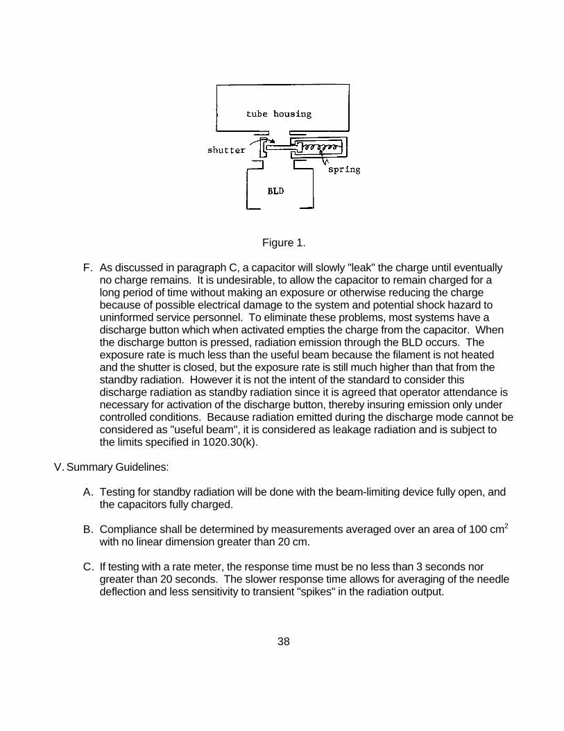
Figure 1.
F. As discussed in paragraph C, a capacitor will slowly "leak" the charge until eventuallyno charge remains. It is undesirable, to allow the capacitor to remain charged for along period of time without making an exposure or otherwise reducing the chargebecause of possible electrical damage to the system and potential shock hazard touninformed service personnel. To eliminate these problems, most systems have adischarge button which when activated empties the charge from the capacitor. Whenthe discharge button is pressed, radiation emission through the BLD occurs. Theexposure rate is much less than the useful beam because the filament is not heatedand the shutter is closed, but the exposure rate is still much higher than that from thestandby radiation. However it is not the intent of the standard to consider thisdischarge radiation as standby radiation since it is agreed that operator attendance isnecessary for activation of the discharge button, thereby insuring emission only undercontrolled conditions. Because radiation emitted during the discharge mode cannot beconsidered as "useful beam", it is considered as leakage radiation and is subject tothe limits specified in 1020.30(k).
V. Summary Guidelines:
A. Testing for standby radiation will be done with the beam-limiting device fully open, andthe capacitors fully charged.
B. Compliance shall be determined by measurements averaged over an area of 100 cm2
with no linear dimension greater than 20 cm.
C. If testing with a rate meter, the response time must be no less than 3 seconds norgreater than 20 seconds. The slower response time allows for averaging of the needledeflection and less sensitivity to transient "spikes" in the radiation output.
38

D. If testing with an integrating instrument, a measurement time of approximately 2minutes is recommended. Because of this long measuring time, it may be necessaryto periodically recharge the capacitors by manually activating the "charge" switch whenthe tube potential drops by more than 5 kV.
E. The system discharges by the activation a "discharge" switch or deactivation of inputpower, the test for will be conducted similar to the leakage requirements at 100 cmfrom the x-ray source. The limit will be determined by the maximum exposure perdischarge times the number of discharges in one hour (duty cycle).
39
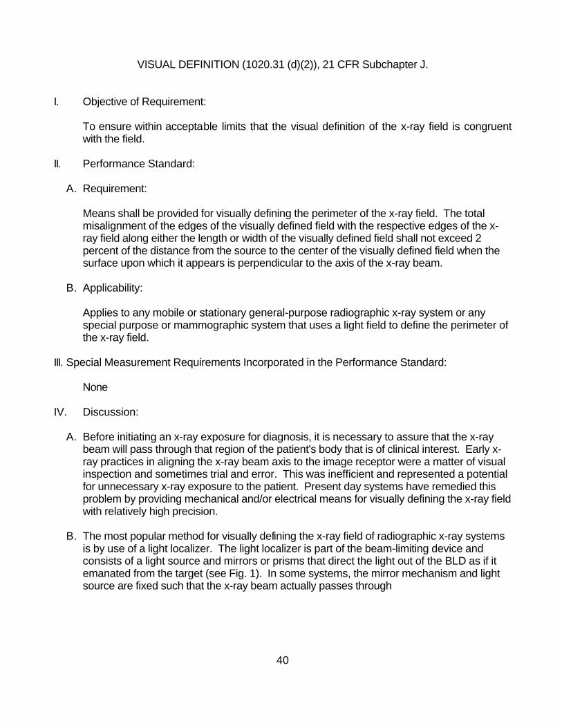
VISUAL DEFINITION (1020.31 (d)(2)), 21 CFR Subchapter J.
I. Objective of Requirement:
To ensure within acceptable limits that the visual definition of the x-ray field is congruentwith the field.
II. Performance Standard:
A. Requirement:
Means shall be provided for visually defining the perimeter of the x-ray field. The totalmisalignment of the edges of the visually defined field with the respective edges of the x-ray field along either the length or width of the visually defined field shall not exceed 2percent of the distance from the source to the center of the visually defined field when thesurface upon which it appears is perpendicular to the axis of the x-ray beam.
B. Applicability:
Applies to any mobile or stationary general-purpose radiographic x-ray system or anyspecial purpose or mammographic system that uses a light field to define the perimeter ofthe x-ray field.
III. Special Measurement Requirements Incorporated in the Performance Standard:
None
IV. Discussion:
A. Before initiating an x-ray exposure for diagnosis, it is necessary to assure that the x-raybeam will pass through that region of the patient's body that is of clinical interest. Early x-ray practices in aligning the x-ray beam axis to the image receptor were a matter of visualinspection and sometimes trial and error. This was inefficient and represented a potentialfor unnecessary x-ray exposure to the patient. Present day systems have remedied thisproblem by providing mechanical and/or electrical means for visually defining the x-ray fieldwith relatively high precision.
B. The most popular method for visually defining the x-ray field of radiographic x-ray systemsis by use of a light localizer. The light localizer is part of the beam-limiting device andconsists of a light source and mirrors or prisms that direct the light out of the BLD as if itemanated from the target (see Fig. 1). In some systems, the mirror mechanism and lightsource are fixed such that the x-ray beam actually passes through
40

the mirror, making it part of the inherent filtration. In others, the mirror is hinged so thatduring an x-ray exposure it retracts out of the path of the beam.
Figure 1.
The system is designed such that the x-ray field will be congruent with the light field, thusallowing the radiographer to position the patient and align the x-ray beam axis precisely byusing the light localizer prior to the exposure.
C. Although the objective of the design is to assure exact congruence of the light field and x-ray field, several factors such as production tolerances and improper assembly oradjustment often cause the respective fields to be dissimilar in size and/or misaligned. The federal performance standard allows for a finite amount of misalignment between thelight field and x-ray field. Figure 2 illustrates the common types of misalignments typical ofx-ray systems.
Figure 2.
41

The total misalignment along one direction is the sum of the misalignments at each edge(e.g., a+b in the first illustration of figure 2). This misalignment cannot exceed 2 percent ofthe source-to-image distance (SID).
V. Summary Guidelines
A. When testing for light field/x-ray field congruence, since an image of the light field itselfdoes not actually show up on the image receptor, the edges must be marked with radio-opaque strips to indicate the perimeter.
B. During testing, an image receptor must be used that is substantially larger than the lightfield/x-ray field. This is to assure that all four edges of both the light field and x-ray field willbe imaged even if grossly misaligned.
C. Sometimes the room lights may be too bright to see the edges of the light field clearly. When testing under these conditions, the room lights should be dimmed or extinguisheduntil the perimeter of the light field is marked.
D. It is the manufacturer's responsibility to assure that the tolerances on the x-ray field to lightfield alignment should be sufficient to assure that the x-ray field to image receptoralignment conditions can be met.
42
Related Documents