Resolving the Growth of 3D Colloidal Nanoparticle Superlattices by Real-Time Small-Angle X‑ray Scattering Chenguang Lu,* Austin J. Akey, Clayton J. Dahlman, Datong Zhang, and Irving P. Herman* Department of Applied Physics and Applied Mathematics, Columbia University, New York, New York 10027, United States * S Supporting Information ABSTRACT: The kinetics and intricate interactions governing the growth of 3D single nanoparticle (NP) superlattices (SLs, SNSLs) and binary NP SLs (BNSLs) in solution are understood by combining controlled solvent evaporation and in situ, real- time small-angle X-ray scattering (SAXS). For the iron oxide (magnetite) NP SLs studied here, the larger the NP, the farther apart are the NPs when the SNSLs begin to precipitate and the closer they are after ordering. This is explained by a model of NP assembly using van der Waals interactions between magnetite cores in hydrocarbons with a ∼21 zJ Hamaker constant. When forming BNSLs of two different sized NPs, the NPs that are in excess of that needed to achieve the final BNSL stoichiometry are expelled during the BNSL formation, and these expelled NPs can form SNSLs. The long-range ordering of these SNSLs and the BNSLs can occur faster than the NP expulsion. ■ INTRODUCTION Colloidal nanoparticle (NP) superlattice (SL) metamaterials hold the promise of novel and tunable collective properties due to the periodic NP arrangement. 1−6 One challenge in attaining this goal has been the need to supplant empirical methods of SL development by rational design and fabrication. One approach is through surface modification. 2,4−6 Another is with better control of assembly through improved understanding of kinetics while using NPs with the ligands from growth; these NPs may have the practical advantages 3,7−14 of superior cost, materials availability, and scaling-up potential. We show here that we can understand and presumably control NP assembly better through resolving the kinetics and intricate interactions governing the growth of 3D single NP SLs (SNSLs) and binary NP SLs (BNSLs) in solution by combining controlled solvent evaporation and in situ, real-time small-angle X-ray scattering (SAXS). Specifically, we learn how NP size affects the rate of assembly of SNSLs and the mechanism of how coexisting SNSLs and BNSLs form. The mechanism of the self-assembly of such NPs into 2D and 3D SLs has been addressed by several groups by using ex situ methods. 15−20 In situ probing techniques, such as AFM, TEM, and SAXS, have also been used, 21−27 most in real time. 21,23−27 However, there has been little real-time analysis of 3D SNSL formation, such as that by optical probing of several SNSLs 7,23 and SAXS of metal NP SNSLs, 25,26 and apparently none of 3D BNSL formation, in part due to challenges in controllably forming 3D SLs. We have developed a multiple solvent system that enables the growth of large and high-quality 3D NP SL metamaterials, with growth rates slow enough for a detailed SAXS study of the kinetics of ordered NP growth. For the systems studied here, we see that when forming SNSLs, the larger the NP, the farther apart are the NPs when they begin to precipitate and the closer they are after ordering. Also, when forming BNSLs of two different sized NPs, the NPs that are in excess of that needed to achieve the final BNSL stoichiometry are expelled during the BNSL formation, and these expelled NPs can form SNSLs. The long-range ordering of these SNSLs and the BNSLs can occur faster than the NP expulsion. We chose oleic acid-capped iron oxide (magnetite) NPs as a model system for a general analysis of growth because they can be formed with a wide range of diameters (6−15 nm) and high monodispersity 28 and can readily dissolve in common nonpolar solvents at room temperature. ■ EXPERIMENTAL SECTION We developed a multiple solvent system consisting of 72% toluene, 22% decane, and 6% dodecane to slow down the critical moments of solvent evaporation during self-assembly after drop casting the NP solution on a Kapton substrate to achieve successful SL formation, 29,30 as well as to permit SAXS analysis at the Brookhaven National Laboratory NSLS Beamline X9A. Figure S1 in the Supporting Information (SI) depicts the chamber we used for real-time SAXS (maintained at 100 Torr during drying for the SLs in Figures 1, 2, and 4, and 300 Torr for those in Figure 3 to slow down the evaporation even more to improve SAXS temporal resolution). See ref 36 and the SI for more details on NP synthesis, SL assembly, and analysis. ■ RESULTS AND DISCUSSION Establishing Conditions for Growing SNSLs and BNSLs. SL growth conditions were first established without X-ray probing. Figure 1a shows the SEM images of the Received: August 7, 2012 Published: October 3, 2012 Article pubs.acs.org/JACS © 2012 American Chemical Society 18732 dx.doi.org/10.1021/ja307848h | J. Am. Chem. Soc. 2012, 134, 18732−18738

Welcome message from author
This document is posted to help you gain knowledge. Please leave a comment to let me know what you think about it! Share it to your friends and learn new things together.
Transcript

Resolving the Growth of 3D Colloidal Nanoparticle Superlattices byReal-Time Small-Angle X‑ray ScatteringChenguang Lu,* Austin J. Akey, Clayton J. Dahlman, Datong Zhang, and Irving P. Herman*
Department of Applied Physics and Applied Mathematics, Columbia University, New York, New York 10027, United States
*S Supporting Information
ABSTRACT: The kinetics and intricate interactions governingthe growth of 3D single nanoparticle (NP) superlattices (SLs,SNSLs) and binary NP SLs (BNSLs) in solution are understoodby combining controlled solvent evaporation and in situ, real-time small-angle X-ray scattering (SAXS). For the iron oxide(magnetite) NP SLs studied here, the larger the NP, the fartherapart are the NPs when the SNSLs begin to precipitate and thecloser they are after ordering. This is explained by a model ofNP assembly using van der Waals interactions betweenmagnetite cores in hydrocarbons with a ∼21 zJ Hamakerconstant. When forming BNSLs of two different sized NPs, the NPs that are in excess of that needed to achieve the final BNSLstoichiometry are expelled during the BNSL formation, and these expelled NPs can form SNSLs. The long-range ordering ofthese SNSLs and the BNSLs can occur faster than the NP expulsion.
■ INTRODUCTION
Colloidal nanoparticle (NP) superlattice (SL) metamaterialshold the promise of novel and tunable collective properties dueto the periodic NP arrangement.1−6 One challenge in attainingthis goal has been the need to supplant empirical methods ofSL development by rational design and fabrication. Oneapproach is through surface modification.2,4−6 Another is withbetter control of assembly through improved understanding ofkinetics while using NPs with the ligands from growth; theseNPs may have the practical advantages3,7−14 of superior cost,materials availability, and scaling-up potential. We show herethat we can understand and presumably control NP assemblybetter through resolving the kinetics and intricate interactionsgoverning the growth of 3D single NP SLs (SNSLs) and binaryNP SLs (BNSLs) in solution by combining controlled solventevaporation and in situ, real-time small-angle X-ray scattering(SAXS). Specifically, we learn how NP size affects the rate ofassembly of SNSLs and the mechanism of how coexistingSNSLs and BNSLs form.The mechanism of the self-assembly of such NPs into 2D
and 3D SLs has been addressed by several groups by using exsitu methods.15−20 In situ probing techniques, such as AFM,TEM, and SAXS, have also been used,21−27 most in realtime.21,23−27 However, there has been little real-time analysis of3D SNSL formation, such as that by optical probing of severalSNSLs7,23 and SAXS of metal NP SNSLs,25,26 and apparentlynone of 3D BNSL formation, in part due to challenges incontrollably forming 3D SLs. We have developed a multiplesolvent system that enables the growth of large and high-quality3D NP SL metamaterials, with growth rates slow enough for adetailed SAXS study of the kinetics of ordered NP growth. Forthe systems studied here, we see that when forming SNSLs, the
larger the NP, the farther apart are the NPs when they begin toprecipitate and the closer they are after ordering. Also, whenforming BNSLs of two different sized NPs, the NPs that are inexcess of that needed to achieve the final BNSL stoichiometryare expelled during the BNSL formation, and these expelledNPs can form SNSLs. The long-range ordering of these SNSLsand the BNSLs can occur faster than the NP expulsion.We chose oleic acid-capped iron oxide (magnetite) NPs as a
model system for a general analysis of growth because they canbe formed with a wide range of diameters (6−15 nm) and highmonodispersity28 and can readily dissolve in common nonpolarsolvents at room temperature.
■ EXPERIMENTAL SECTIONWe developed a multiple solvent system consisting of 72% toluene,22% decane, and 6% dodecane to slow down the critical moments ofsolvent evaporation during self-assembly after drop casting the NPsolution on a Kapton substrate to achieve successful SL formation,29,30
as well as to permit SAXS analysis at the Brookhaven NationalLaboratory NSLS Beamline X9A. Figure S1 in the SupportingInformation (SI) depicts the chamber we used for real-time SAXS(maintained at 100 Torr during drying for the SLs in Figures 1, 2, and4, and 300 Torr for those in Figure 3 to slow down the evaporationeven more to improve SAXS temporal resolution). See ref 36 and theSI for more details on NP synthesis, SL assembly, and analysis.
■ RESULTS AND DISCUSSIONEstablishing Conditions for Growing SNSLs and
BNSLs. SL growth conditions were first established withoutX-ray probing. Figure 1a shows the SEM images of the
Received: August 7, 2012Published: October 3, 2012
Article
pubs.acs.org/JACS
© 2012 American Chemical Society 18732 dx.doi.org/10.1021/ja307848h | J. Am. Chem. Soc. 2012, 134, 18732−18738

monolithic SNSL pieces from 13.8 nm diameter iron oxideNPs, with average ∼50 μm lateral dimension and ∼10 μmthickness. The Figure 1a inset shows the SAXS pattern forSNSLs of 13.8 nm NPs, which is indexed to a face-centeredcubic ( fcc) structure, as are the SNSLs of NPs examined withdiameters ≥10.6 nm; also see Figure S2a,b. Particles examinedwith diameter ≤8.0 nm form the hexagonal close-packed (hcp)structure, such as the SNSLs of 5.9 nm diameter NPs shown inFigures 1b and S2c. This structure difference is attributed to thedifferent strengths of anisotropic interactions of these NPs. In ahard sphere model, the fcc structure is thermodynamically more
stable than the hcp structure, because the different packingorder causes an entropy difference31 estimated to be on theorder of 10−3 kB per NP. Anisotropic interactions, such as dueto NP electric dipoles or magnetic dipoles, would lower theenergy by aligning the A and C layers, to favor the hcp(ABABAB...) structure over the fcc (ABCABC...) structure. Webelieve the observed hcp structure in 5.9 nm NP SNSLs is dueto stronger anisotropic interactions, electric and/or magneticdipole interactions that override the entropy contribution.Anisotropic dipole interactions are known to be strong enoughto enable NPs to stack in symmetries not expected in hard
Figure 1. (a) SEM images of the side of one piece of the dried 13.8 nm iron oxide NP SNSL film, with the SAXS pattern inset suggesting fccstructure. (b) SEM images the top-view of the 5.9 nm iron oxide NP SNSL, with the SAXS pattern suggesting hcp structure. (c) SEM image of BNSLpieces composed of 5.9 and 12.4 nm iron oxide NPs. (d) Cross section SEM image of a large single crystalline domain of the BNSL in (c) over 1 μm.(e) SAXS diffraction pattern showing a mixture of BNSL and SNSL structures in (c). The indexed peaks are noted as dashed black arcs: A(001),B(100), C(101), D(002)/(110) (degenerate), E(102), and F(111) for the sh BNSL; solid red arcs: G(100), H(101), and I(002) for the hcp SNSL.Lattice constants for the sh are a = b = 15.0 nm, c = 15.0 nm; for the hcp they are a = b = 7.8 nm, c = 12.7 nm. This pattern is obtained with the beamnormal to the substrate. No lattice distortion is observed, in contrast to that seen in samples described in Figures 2 and 4. (f) SEM image of (c)showing the BNSL and the 5.9 nm NP SNSL coexist in close proximity in one sample.
Journal of the American Chemical Society Article
dx.doi.org/10.1021/ja307848h | J. Am. Chem. Soc. 2012, 134, 18732−1873818733

sphere models.32 In future work we will examine if the packingsymmetry can be changed by varying external fields.33
The conditions for growing BNSLs from 12.4 and 5.9 nmiron oxide NPs were also determined, as shown in Figure 1c,d,f(SEM images), and e (diffraction pattern). The ratio of thesolution concentrations of the 5.9 and 12.4 nm NPs for theSAXS study was targeted at the 2:1 needed for AlB2 stacking.An SEM survey of the sample after solvent drying revealed theformation of both the BNSL and a 5.9 nm NP SNSL (Figure1f), with no 12.4 nm NP SNSL formation, so the initial solutionratio was in fact >2:1. This allows a direct comparison betweenthe growth kinetics of SNSLs and BNSLs, which will bediscussed later. The structure of the BNSL is indexed to besimple hexagonal (AlB2 isostructure), as is confirmed by theSEM images in Figure S3. Upon adding extra 12.4 nm particlesto this solution so the ratio would be <2:1, SEM analysisshowed that only the BNSL and 12.4 nm NP SNSL form. Thisindicates that forming the AlB2 BNSL is favored over theseparate formation of SNSLs of these two NPs.Obtaining large 3D BNSLs by drop casting has been difficult.
We believe our success in forming them is due to more carefulsolvent evaporation control, with suitably slowed evaporation atthe critical stage of NP ordering. The BNSLs are smaller thanthe SNSLs we formed from a single component, as seen bySEM and SAXS (with ring patterns for the BNSLs and dotpatterns for the SNSLs). This may be due to disruptions by theNP expulsion described below.Monitoring SNSL Growth by SAXS. With the desired
growth conditions established, we used SAXS to probe thegrowth in real time. Figure 2a−c (and Movie S1) show a series
of diffraction patterns collected during the growth of 13.8 nmNP SNSLs. The diffraction pattern evolves from the form factorof randomly positioned NPs in solution to strong diffractionspots, which are indexed to highly oriented fcc structures(Figure S4). This shows that the (111) plane is orientedparallel to the substrate, which is confirmed by a survey overlarge areas by SEM. We believe this orientation occurs becausethe growth of the 3D SL starts with 2D arrays at the top liquidsurface, which then grow/stack in the vertical direction. Such2D NP packing at the liquid surface has been reported manytimes for NP self-assembly.3,8,27
The diffraction spots showed a q-value increase during theevolution (Movie S1), which indicates a lattice contraction.After dividing the SAXS patterns by the form factor (the SAXSpattern at 240 s), we obtained the structure factor of the SL,which gives us more details of the evolution of SL. Figure 2dshows the evolution of the structure factor peaks along the qxaxis, and Figure 2e shows the evolution of the peak positionand width of the (220) planes. The in-plane q increases by∼0.056 nm−1, i.e., a ∼0.55 nm contraction between the (220)planes. Such lattice contraction is consistent with earlier reportson 2D and 3D NP superlattice growth.26,27 The peak widthdecreases from 0.0594 to 0.0525 nm−1 and then increases to0.0560 nm−1, which suggests that while the SNSL latticeconstant is decreasing during drying, the SNSL grows in sizeand then cracks into smaller pieces. The final cracking of theSNSL was also confirmed by SEM images (Figure 2f). As hasbeen seen earlier,17,27 this cracking may be due to strain arisingfrom the adhesion between the 3D SNSL and the substrate,
Figure 2. SAXS patterns during SNSL drying, with (a−c) SAXS patterns of 13.8 nm iron oxide NP solution during solvent drying, sampled at 300,480, and 600 s, respectively. The peaks are indexed to fcc compressed along the [111] direction, with a = 22.5 nm and 6% compression in (b) andwith a = 21.5 nm and 7% compression in (c). The SLs are highly oriented, with the (111) plane parallel to the substrate. Complete indexing can befound in the Figure S4. (d) Evolution of the structure factor peaks along the qx axis. (The structure factor is the quotient of the diffraction patternand the form factor, which is taken as the SAXS pattern at 240 s.) Note the glassy stage hump at qx ∼0.4 nm−1, on the 420 s green curve before theSL forms. The structure factor at 300 s is flat, indicating that there is no ordering in the NP solution. (e) Evolution of the qx peak value and width ofthe (220) peak. (f) SEM images showing the SL cracks after the solvent evaporates, which explains the increase of the peak width at the final stagesof drying.
Journal of the American Chemical Society Article
dx.doi.org/10.1021/ja307848h | J. Am. Chem. Soc. 2012, 134, 18732−1873818734
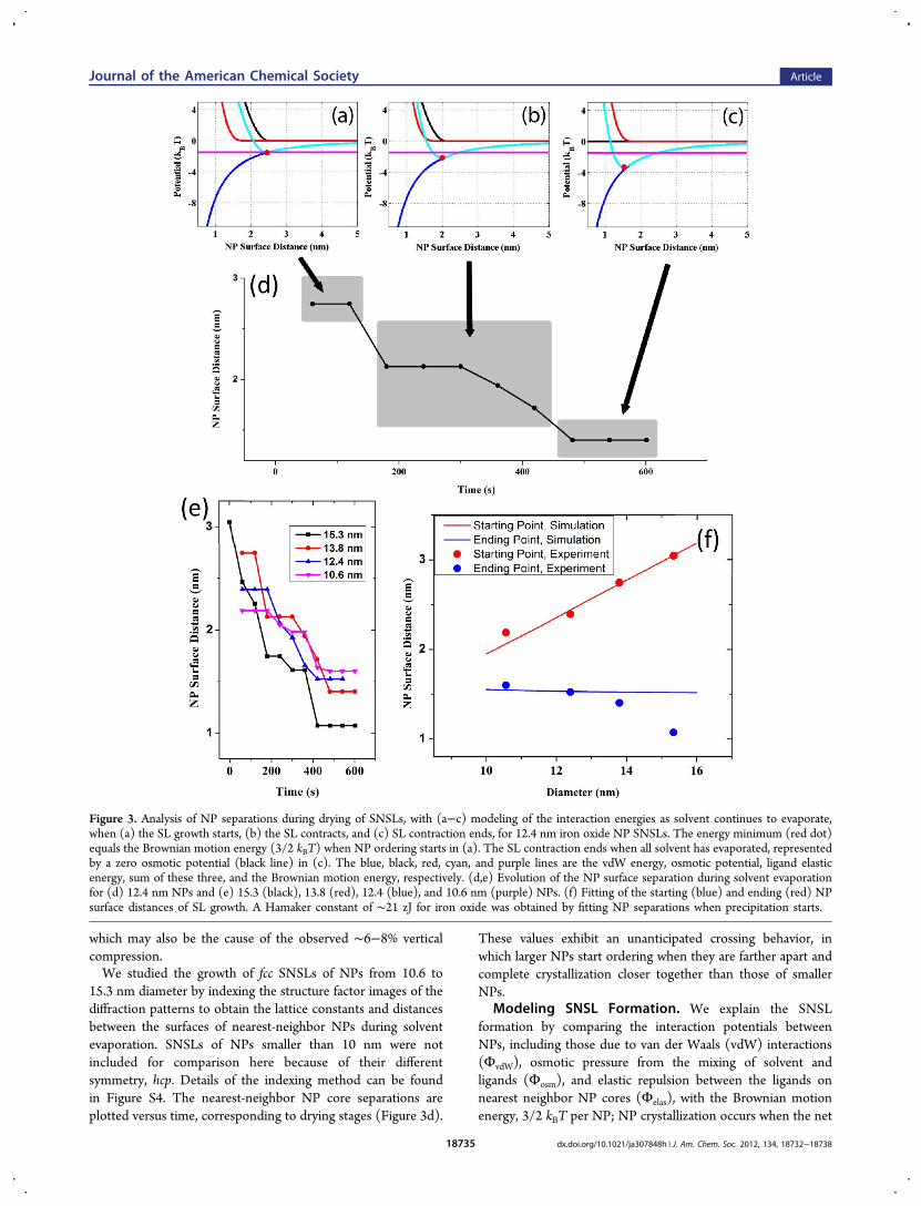
which may also be the cause of the observed ∼6−8% verticalcompression.We studied the growth of fcc SNSLs of NPs from 10.6 to
15.3 nm diameter by indexing the structure factor images of thediffraction patterns to obtain the lattice constants and distancesbetween the surfaces of nearest-neighbor NPs during solventevaporation. SNSLs of NPs smaller than 10 nm were notincluded for comparison here because of their differentsymmetry, hcp. Details of the indexing method can be foundin Figure S4. The nearest-neighbor NP core separations areplotted versus time, corresponding to drying stages (Figure 3d).
These values exhibit an unanticipated crossing behavior, inwhich larger NPs start ordering when they are farther apart andcomplete crystallization closer together than those of smallerNPs.
Modeling SNSL Formation. We explain the SNSLformation by comparing the interaction potentials betweenNPs, including those due to van der Waals (vdW) interactions(ΦvdW), osmotic pressure from the mixing of solvent andligands (Φosm), and elastic repulsion between the ligands onnearest neighbor NP cores (Φelas), with the Brownian motionenergy, 3/2 kBT per NP; NP crystallization occurs when the net
Figure 3. Analysis of NP separations during drying of SNSLs, with (a−c) modeling of the interaction energies as solvent continues to evaporate,when (a) the SL growth starts, (b) the SL contracts, and (c) SL contraction ends, for 12.4 nm iron oxide NP SNSLs. The energy minimum (red dot)equals the Brownian motion energy (3/2 kBT) when NP ordering starts in (a). The SL contraction ends when all solvent has evaporated, representedby a zero osmotic potential (black line) in (c). The blue, black, red, cyan, and purple lines are the vdW energy, osmotic potential, ligand elasticenergy, sum of these three, and the Brownian motion energy, respectively. (d,e) Evolution of the NP surface separation during solvent evaporationfor (d) 12.4 nm NPs and (e) 15.3 (black), 13.8 (red), 12.4 (blue), and 10.6 nm (purple) NPs. (f) Fitting of the starting (blue) and ending (red) NPsurface distances of SL growth. A Hamaker constant of ∼21 zJ for iron oxide was obtained by fitting NP separations when precipitation starts.
Journal of the American Chemical Society Article
dx.doi.org/10.1021/ja307848h | J. Am. Chem. Soc. 2012, 134, 18732−1873818735

attraction energy exceeds the kinetic energy per NP. Thepotential profiles for pairs of NPs were determined using eqsS2−S4.34Figure 3a compares the energies of the different interactions
between 12.4 nm NPs (6× each energy in eqs S2−S4, toaccount for the 12 nearest neighbors of each NP, withoutdouble counting) and their sum when there is sufficient solventevaporation for the onset of precipitation, which is when thisinteraction energy first equals the Brownian motion energy, 3/2kBT per NP. Additional removal of solvent thins the effectiveligand shell further, which causes the minimum of the totalpotential curve to dip below the Brownian motion energy ateven smaller NP separations, enabling continued precipitationof NPs from solution (Figure 3b). Larger NPs precipitate whenthey are farther apart than smaller NPs because of theirstronger core−core vdW forces and when they precipitate
slowly enough, as here, in the energetically more favorableSNSL structure. The solvent system, consisting of threesolvents with very different vapor pressures, slows down thedrying, which allows the precipitated NPs to reach equilibrium,i.e., to attain ordered close packing rather than glass-likepacking. An SEM survey over very large areas confirms theSNSL structure to be dominant over randomly packed NPs,although initially there is a glass-like stage (Figure 2d). Thefinal distance between NP core surfaces is determined by theNP vdW attraction and ligand repulsions in the absence ofsolvent (Figure 3c), where the stronger vdW forces of the largerNPs compress the ligands more, leading to smaller surface−surface NP distances than those of smaller NPs with the sameligand structure. This evolution is also described in Movie S2.These observations and model predictions are also consistentwith the well-known difficulty of dissolving larger NPs.
Figure 4. (a−c) SAXS evolution of the binary NP mixture film during solvent evaporation to form BNSLs, with 5.9 and 12.4 nm iron oxide NPsmixed with ∼2:1 ratio in the drop cast solution. Ordering occurs first with the 5.9 nm NP SNSL at 600 s in (b) and then with the BNSL at 1080 s in(c). The 5.9 nm NP SNSL forms the hcp structure, and the BNSL forms a sh structure (AlB2 type). The indexed peaks are the following: dashedgreen arcs (001), (100), (101), (002)/(110) (degenerate), (102), and (111) for the sh BNSL; dashed blue arcs (100), (101), and (002) for the hcpSNSL. The lattice constants are obtained by fitting the radially integrated peaks in (d), which for the sh are a = b = 15.3 nm, c = 15.3 nm, and for thehcp are a = b = 7.9 nm, c = 12.9 nm. This pattern is obtained with the beam hitting the substrate at a 0.4° angle. 5% lattice compression is observedalong the z-axis, which is included in the radial integration and indexing. (d) Evolution of the radially integrated structure factor peaks of the binaryNP SL assembly. The structure factor is the quotient of the diffraction pattern and the form factor (which is the pattern at 360 s). The first threepeaks of the BNSL can be identified, and the SNSL peaks overlap higher-order BNSL peaks to form the peak denoted by *. (e) Differences ofsuccessive traces in (d), which indicate peak growth at different stages. Growth of the BNSL peaks at 1080 s is evident. (f) Schematic of the processof the expulsion of smaller 5.9 nm NPs from the binary NP mixture as it forms a 2:1 ratio of the 5.9:12.4 nm NPs in the AlB2-type BNSL stacking.
Journal of the American Chemical Society Article
dx.doi.org/10.1021/ja307848h | J. Am. Chem. Soc. 2012, 134, 18732−1873818736
The NP surface distance is plotted in Figure 3d,e duringevaporation for the four particle sizes examined. The startingand ending separations are plotted in Figure 3f, along withmodel predictions (analogs of Figure 3a,c for each NP size) fitwith a Hamaker constant of ∼21 zJ, which is in good agreementwith recent theoretical prediction (9−29 zJ for iron oxides).35
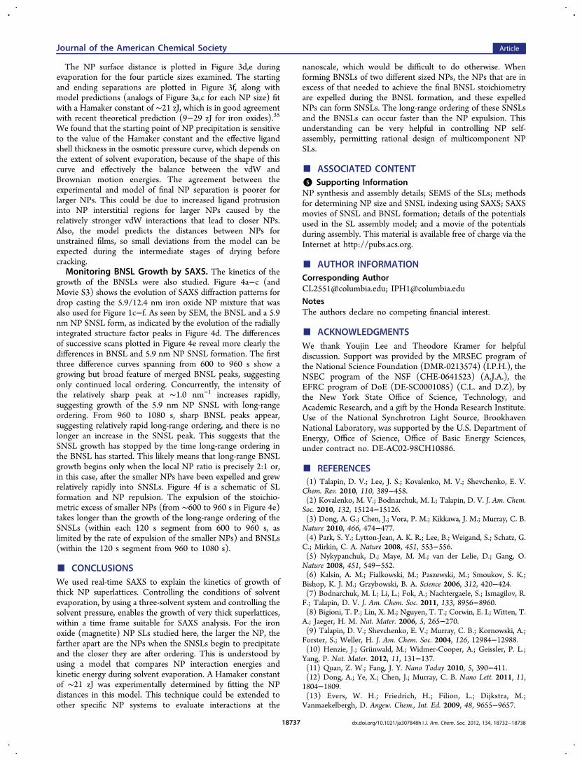
We found that the starting point of NP precipitation is sensitiveto the value of the Hamaker constant and the effective ligandshell thickness in the osmotic pressure curve, which depends onthe extent of solvent evaporation, because of the shape of thiscurve and effectively the balance between the vdW andBrownian motion energies. The agreement between theexperimental and model of final NP separation is poorer forlarger NPs. This could be due to increased ligand protrusioninto NP interstitial regions for larger NPs caused by therelatively stronger vdW interactions that lead to closer NPs.Also, the model predicts the distances between NPs forunstrained films, so small deviations from the model can beexpected during the intermediate stages of drying beforecracking.Monitoring BNSL Growth by SAXS. The kinetics of the
growth of the BNSLs were also studied. Figure 4a−c (andMovie S3) shows the evolution of SAXS diffraction patterns fordrop casting the 5.9/12.4 nm iron oxide NP mixture that wasalso used for Figure 1c−f. As seen by SEM, the BNSL and a 5.9nm NP SNSL form, as indicated by the evolution of the radiallyintegrated structure factor peaks in Figure 4d. The differencesof successive scans plotted in Figure 4e reveal more clearly thedifferences in BNSL and 5.9 nm NP SNSL formation. The firstthree difference curves spanning from 600 to 960 s show agrowing but broad feature of merged BNSL peaks, suggestingonly continued local ordering. Concurrently, the intensity ofthe relatively sharp peak at ∼1.0 nm−1 increases rapidly,suggesting growth of the 5.9 nm NP SNSL with long-rangeordering. From 960 to 1080 s, sharp BNSL peaks appear,suggesting relatively rapid long-range ordering, and there is nolonger an increase in the SNSL peak. This suggests that theSNSL growth has stopped by the time long-range ordering inthe BNSL has started. This likely means that long-range BNSLgrowth begins only when the local NP ratio is precisely 2:1 or,in this case, after the smaller NPs have been expelled and grewrelatively rapidly into SNSLs. Figure 4f is a schematic of SLformation and NP repulsion. The expulsion of the stoichio-metric excess of smaller NPs (from ∼600 to 960 s in Figure 4e)takes longer than the growth of the long-range ordering of theSNSLs (within each 120 s segment from 600 to 960 s, aslimited by the rate of expulsion of the smaller NPs) and BNSLs(within the 120 s segment from 960 to 1080 s).
■ CONCLUSIONSWe used real-time SAXS to explain the kinetics of growth ofthick NP superlattices. Controlling the conditions of solventevaporation, by using a three-solvent system and controlling thesolvent pressure, enables the growth of very thick superlattices,within a time frame suitable for SAXS analysis. For the ironoxide (magnetite) NP SLs studied here, the larger the NP, thefarther apart are the NPs when the SNSLs begin to precipitateand the closer they are after ordering. This is understood byusing a model that compares NP interaction energies andkinetic energy during solvent evaporation. A Hamaker constantof ∼21 zJ was experimentally determined by fitting the NPdistances in this model. This technique could be extended toother specific NP systems to evaluate interactions at the
nanoscale, which would be difficult to do otherwise. Whenforming BNSLs of two different sized NPs, the NPs that are inexcess of that needed to achieve the final BNSL stoichiometryare expelled during the BNSL formation, and these expelledNPs can form SNSLs. The long-range ordering of these SNSLsand the BNSLs can occur faster than the NP expulsion. Thisunderstanding can be very helpful in controlling NP self-assembly, permitting rational design of multicomponent NPSLs.
■ ASSOCIATED CONTENT*S Supporting InformationNP synthesis and assembly details; SEMS of the SLs; methodsfor determining NP size and SNSL indexing using SAXS; SAXSmovies of SNSL and BNSL formation; details of the potentialsused in the SL assembly model; and a movie of the potentialsduring assembly. This material is available free of charge via theInternet at http://pubs.acs.org.
■ AUTHOR INFORMATIONCorresponding [email protected]; [email protected] authors declare no competing financial interest.
■ ACKNOWLEDGMENTSWe thank Youjin Lee and Theodore Kramer for helpfuldiscussion. Support was provided by the MRSEC program ofthe National Science Foundation (DMR-0213574) (I.P.H.), theNSEC program of the NSF (CHE-0641523) (A.J.A.), theEFRC program of DoE (DE-SC0001085) (C.L. and D.Z), bythe New York State Office of Science, Technology, andAcademic Research, and a gift by the Honda Research Institute.Use of the National Synchrotron Light Source, BrookhavenNational Laboratory, was supported by the U.S. Department ofEnergy, Office of Science, Office of Basic Energy Sciences,under contract no. DE-AC02-98CH10886.
■ REFERENCES(1) Talapin, D. V.; Lee, J. S.; Kovalenko, M. V.; Shevchenko, E. V.Chem. Rev. 2010, 110, 389−458.(2) Kovalenko, M. V.; Bodnarchuk, M. I.; Talapin, D. V. J. Am. Chem.Soc. 2010, 132, 15124−15126.(3) Dong, A. G.; Chen, J.; Vora, P. M.; Kikkawa, J. M.; Murray, C. B.Nature 2010, 466, 474−477.(4) Park, S. Y.; Lytton-Jean, A. K. R.; Lee, B.; Weigand, S.; Schatz, G.C.; Mirkin, C. A. Nature 2008, 451, 553−556.(5) Nykypanchuk, D.; Maye, M. M.; van der Lelie, D.; Gang, O.Nature 2008, 451, 549−552.(6) Kalsin, A. M.; Fialkowski, M.; Paszewski, M.; Smoukov, S. K.;Bishop, K. J. M.; Grzybowski, B. A. Science 2006, 312, 420−424.(7) Bodnarchuk, M. I.; Li, L.; Fok, A.; Nachtergaele, S.; Ismagilov, R.F.; Talapin, D. V. J. Am. Chem. Soc. 2011, 133, 8956−8960.(8) Bigioni, T. P.; Lin, X. M.; Nguyen, T. T.; Corwin, E. I.; Witten, T.A.; Jaeger, H. M. Nat. Mater. 2006, 5, 265−270.(9) Talapin, D. V.; Shevchenko, E. V.; Murray, C. B.; Kornowski, A.;Forster, S.; Weller, H. J. Am. Chem. Soc. 2004, 126, 12984−12988.(10) Henzie, J.; Grunwald, M.; Widmer-Cooper, A.; Geissler, P. L.;Yang, P. Nat. Mater. 2012, 11, 131−137.(11) Quan, Z. W.; Fang, J. Y. Nano Today 2010, 5, 390−411.(12) Dong, A.; Ye, X.; Chen, J.; Murray, C. B. Nano Lett. 2011, 11,1804−1809.(13) Evers, W. H.; Friedrich, H.; Filion, L.; Dijkstra, M.;Vanmaekelbergh, D. Angew. Chem., Int. Ed. 2009, 48, 9655−9657.
Journal of the American Chemical Society Article
dx.doi.org/10.1021/ja307848h | J. Am. Chem. Soc. 2012, 134, 18732−1873818737

(14) Tang, Z. Y.; Zhang, Z. L.; Wang, Y.; Glotzer, S. C.; Kotov, N. A.Science 2006, 314, 274−278.(15) Talapin, D. V.; Shevchenko, E. V.; Bodnarchuk, M. I.; Ye, X. C.;Chen, J.; Murray, C. B. Nature 2009, 461, 964−967.(16) Bodnarchuk, M. I.; Kovalenko, M. V.; Heiss, W.; Talapin, D. V.J. Am. Chem. Soc. 2010, 132, 11967−11977.(17) Smith, D. K.; Goodfellow, B.; Smilgies, D. M.; Korgel, B. A. J.Am. Chem. Soc. 2009, 131, 3281−3290.(18) Choi, J. J.; Bealing, C. R.; Bian, K. F.; Hughes, K. J.; Zhang, W.Y.; Smilgies, D. M.; Hennig, R. G.; Engstrom, J. R.; Hanrath, T. J. Am.Chem. Soc. 2011, 133, 3131−3138.(19) Bodnarchuk, M. I.; Sheychenko, E. V.; Talapin, D. V. J. Am.Chem. Soc. 2011, 133, 20837−20849.(20) Chen, Z. Y.; Moore, J.; Radtke, G.; Sirringhaus, H.; O’Brien, S. J.Am. Chem. Soc. 2007, 129, 15702−15709.(21) Lee, B.; Podsiadlo, P.; Rupich, S.; Talapin, D. V.; Rajh, T.;Shevchenko, E. V. J. Am. Chem. Soc. 2009, 131, 16386−16388.(22) Ge, G.; Brus, L. E. Nano Lett. 2001, 1, 219−222.(23) Yang, L.; Gao, K. Y.; Luo, Y. H.; Luo, J. H.; Li, D. M.; Meng, Q.B. Langmuir 2011, 27, 1700−1706.(24) Park, J.; Zheng, H.; Lee, W. C.; Geissler, P. L.; Rabani, E.;Alivisatos, A. P. ACS Nano 2012, 6, 2078−2085.(25) Abecassis, B.; Testard, F.; Spalla, O. Phys. Rev. Lett. 2008, 100,115504.(26) Connolly, S.; Fullam, S.; Korgel, B.; Fitzmaurice, D. J. Am.Chem. Soc. 1998, 120, 2969−2970.(27) Jiang, Z.; Lin, X. M.; Sprung, M.; Narayanan, S.; Wang, J. NanoLett. 2010, 10, 799−803.(28) Hyeon, T.; Lee, S. S.; Park, J.; Chung, Y.; Bin Na, H. J. Am.Chem. Soc. 2001, 123, 12798−12801.(29) Lu, C.; Chen, Z.; O’Brien, S. Chem. Mater. 2008, 20, 3594−3600.(30) Akey, A.; Lu, C. G.; Yang, L.; Herman, I. P. Nano Lett. 2010, 10,1517−1521.(31) Bolhuis, P. G.; Frenkel, D.; Mau, S. C.; Huse, D. A. Nature 1997,388, 235−236.(32) Talapin, D. V.; Shevchenko, E. V.; Murray, C. B.; Titov, A. V.;Kral, P. Nano Lett. 2007, 7, 1213−1219.(33) Ryan, K. M.; Mastroianni, A.; Stancil, K. A.; Liu, H.; Alivisatos,A. P. Nano Lett. 2006, 6, 1479−1482.(34) Saunders, S. R.; Eden, M. R.; Roberts, C. B. J. Phys. Chem. C2011, 115, 4603−4610.(35) Faure, B.; Salazar-Alvarez, G.; Bergstrom, L. Langmuir 2011, 27,8659−8664.(36) Lu, C.; Akey, A. A.; Herman, I. P. Appl. Phys. Lett. 2012, 101,133109.
Journal of the American Chemical Society Article
dx.doi.org/10.1021/ja307848h | J. Am. Chem. Soc. 2012, 134, 18732−1873818738
Related Documents