21 ` eme Congr` es Fran¸ cais de M´ ecanique Bordeaux, 26 au 30 aoˆ ut 2013 Resolution of spherical parallel Manipulator (SPM) forward kinematic model (FKM) near the singularities H. Saafi a , M. A. Laribi a , S. Zeghloul a a. Dept. GMSC, Pprime Institute, CNRS - University of Poitiers - ENSMA - UPR 3346, France houssem.saafi@univ-poitiers.fr, [email protected], [email protected] Abstract : The parallel manipulators present good performances, but near the singularities their dexterity and accuracy are deteriorated. In this paper, we propose an approach to eliminate the disturbance caused by the presence of singularities in the parallel manipulator workspace. The effect of parallel singularity on the resolution of the forward kinematics model (FKM) is eliminated by adding a redundant sensor in one passive joint of the parallel manipulator. An investigation is made for choosing the best passive joint that gives the maximum of accuracy on the resolution of FKM. The proposed approach is applied to a spherical parallel manipulator (SPM) for tele-manipulation with haptic feedback. An experimental validation is made to prove the use benefit of the redundant sensor on the FKM. A singularity and kinematics study of the SPM is developed. Keywords : Spherical Parallel Manipulator, Forward Kinematic Model, Singularity. 1 Introduction In general, parallel manipulators are much more accurate than serial manipulators. This is valid only in the non-singular areas of the workspace. Indeed, for the case of serial manipulators singularity is located just at the border of the workspace. But for parallel robots, singularity may be at the border or inside the workspace. This type of singularity is called parallel singularity. Most works try to eliminate this type of singularity from the workspace of the robot by optimizing its geometry [6]-[7]. But by improving the kinematic behavior, the parallel robot structure becomes bigger and a problem of interference is generated. Few studies have focused on this type of singularity. For the case of 3- RRR spherical parallel manipulator, we note only the work of Bonev and Gosselin [1]. The presented SPM is used as haptic device in tele-operation system for medical application [2]. The SPM is used to control a surgery robot. The surgeon movement are identified by solving the FKM of the SPM. The robot is equipped by absolute sensors to determine the active angle which will be used to find the orientation of the end effector. In this work, we study the kinematic behavior and accuracy of the SPM near the type-2 singularity regions. The paper is organized as follows : in section II, we present the forward kinematic model of the SPM. Parallel and serial singularities are defined in the section III. The section IV deals with the modifications applied on the FKM by adding the fourth sensor. Two cases will be presented and a comparative study in terms of FKM accuracy for each case is discussed. An experimental comparison is made in section V to show the benefits of the redundant sensor on accuracy of the FKM. Conclusions and perspectives are presented at the end of the paper. 2 Forward Kinematic Model The SPM is a robot with three degrees of freedom (DOF) of rotation. Each leg of the SPM is made of two links and three revolute joints. All the axes of the revolute joints are intersecting in one point, called the center of rotation (CoR) of the robot. Each link is characterized by the radius and the angle between its two revolute joints (see Figure 1.a). These parameters are constants and represent the dimension of the link. The three revolute joints with the base are actuated. The three legs are 1

Welcome message from author
This document is posted to help you gain knowledge. Please leave a comment to let me know what you think about it! Share it to your friends and learn new things together.
Transcript
21eme Congres Francais de Mecanique Bordeaux, 26 au 30 aout 2013
Resolution of spherical parallel Manipulator (SPM)
forward kinematic model (FKM) near the singularities
H. Saafia, M. A. Laribia, S. Zeghloula
a. Dept. GMSC, Pprime Institute, CNRS - University of Poitiers - ENSMA - UPR 3346, [email protected], [email protected], [email protected]
Abstract :
The parallel manipulators present good performances, but near the singularities their dexterity andaccuracy are deteriorated. In this paper, we propose an approach to eliminate the disturbance causedby the presence of singularities in the parallel manipulator workspace. The effect of parallel singularityon the resolution of the forward kinematics model (FKM) is eliminated by adding a redundant sensorin one passive joint of the parallel manipulator. An investigation is made for choosing the best passivejoint that gives the maximum of accuracy on the resolution of FKM. The proposed approach is appliedto a spherical parallel manipulator (SPM) for tele-manipulation with haptic feedback. An experimentalvalidation is made to prove the use benefit of the redundant sensor on the FKM. A singularity andkinematics study of the SPM is developed.
Keywords : Spherical Parallel Manipulator, Forward Kinematic Model, Singularity.
1 Introduction
In general, parallel manipulators are much more accurate than serial manipulators. This is valid onlyin the non-singular areas of the workspace. Indeed, for the case of serial manipulators singularityis located just at the border of the workspace. But for parallel robots, singularity may be at theborder or inside the workspace. This type of singularity is called parallel singularity. Most works tryto eliminate this type of singularity from the workspace of the robot by optimizing its geometry [6]-[7].But by improving the kinematic behavior, the parallel robot structure becomes bigger and a problemof interference is generated. Few studies have focused on this type of singularity. For the case of 3-RRR spherical parallel manipulator, we note only the work of Bonev and Gosselin [1]. The presentedSPM is used as haptic device in tele-operation system for medical application [2]. The SPM is usedto control a surgery robot. The surgeon movement are identified by solving the FKM of the SPM.The robot is equipped by absolute sensors to determine the active angle which will be used to findthe orientation of the end effector. In this work, we study the kinematic behavior and accuracy of theSPM near the type-2 singularity regions. The paper is organized as follows : in section II, we presentthe forward kinematic model of the SPM. Parallel and serial singularities are defined in the sectionIII. The section IV deals with the modifications applied on the FKM by adding the fourth sensor. Twocases will be presented and a comparative study in terms of FKM accuracy for each case is discussed.An experimental comparison is made in section V to show the benefits of the redundant sensor onaccuracy of the FKM. Conclusions and perspectives are presented at the end of the paper.
2 Forward Kinematic Model
The SPM is a robot with three degrees of freedom (DOF) of rotation. Each leg of the SPM is madeof two links and three revolute joints. All the axes of the revolute joints are intersecting in one point,called the center of rotation (CoR) of the robot. Each link is characterized by the radius and theangle between its two revolute joints (see Figure 1.a). These parameters are constants and representthe dimension of the link. The three revolute joints with the base are actuated. The three legs are
1
21eme Congres Francais de Mecanique Bordeaux, 26 au 30 aout 2013
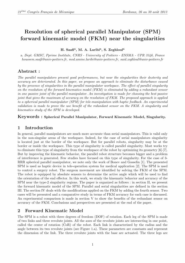
identical and the actuated joint axes are located along the x, y and z axes, respectively. The kinematicsof the robot is described in detail in the work of Chaker et al. [2]. The operational vector parametersX=[ψ, θ, ϕ]T , are the three ZXZ-Euler angles of the platform, representing the orientation of theplatform with respect to the base. The FKM of parallel manipulators has proven to be very complex.If we stay into the domain of spherical mechanisms, the direct model calculates the orientation of theend-effector X for a given position of the actuators (θ1A, θ1B, θ1C). It is noted from the literature thatmost studies were conducted to solve the direct kinematics. The FKM studied in Gosselin et al. [4]is described by an 8-degree polynomial and has 8 possible solutions. Shaoping et al. [5] proposed arobust procedure to determine the orientation of the end-effector using the input/output equations ofspherical four-bar linkages. In this paper, the FKM of the SPM is solved using the method proposedby Bai et al. [5]. The proposed approach is based on writing the input/output (I/O) equations of 4bars spherical mechanism for the following two chains : A2-A3-B3-B2 and A3-A2-C2-C3 (see Figure1.b). For the chain A2-A3-B3-B2 the equation is :
L1(ξ)cos(σ) +M1(ξ)sin(σ) +N1(ξ) = 0 (1)
For the chain A3-A2-C2-C3 the equation is :
L2(ξ)cos(σ) +M2(ξ)sin(σ) +N2(ξ) = 0 (2)
where ξ is the angle ( A3, A2, B2), σ is the angle ( A2, A3, B3) and Li(ξ), Mi(ξ) and Ni(ξ) (i=1,2) arevariables that depend on cos(ξ) and sin(ξ). From the system composed by equation (1) and (2), cos(σ)
Figure 1 – Spherical parallel manipulator (SPM) : (a) Geometrical parameters of leg A. (b) Kinema-tics of the SPM.
and sin(σ) are obtained as :{cos(σ) = (M1N2 −M2N1)/(L1M2 − L2M1) (a)sin(σ) = −(L1N2 − L2N1)/(L1M2 − L2M1) (b)
(3)
First, the possible solution of ξ was found by solving the equation (4) generated by writing (3.a)2+(3.b)2
which depend only of ξ.
N22L
21+2L1M2L1M1−2L2N2L1N1+N2
2M21 −L2
2M21 −2M2N2M1N1−M2
2L21+L1
2N21 +M2
2N21 = 0 (4)
The solution of ξ is used then to calculate σ using equation (3). For a given vector (θ1A, θ1B, θ1C), wehave eight solutions for ξ and σ. Each pair (ξ, σ) gives an orientation (ψ, θ, ϕ) of the end-effector.
3 SPM singularity and the effect on the resolution of FKM
The kinematic model of the robot is described by the joints velocity vector Θ and the moving platformoutput velocity ω. The relation between Θ and ω is written as follows :
A · ω = B · Θ (5)
2
21eme Congres Francais de Mecanique Bordeaux, 26 au 30 aout 2013
For a fully-parallel manipulator, the matrix B is a diagonal matrix and it is easy to invert it. Therefore,we propose to use the definition of the inverse Jacobian matrix in the input/output velocity relationdefined by Eq. (6).
Θ = B−1A · ω = J−1 · ω (6)
The jacobian matrix, J, linearly relates the actuated joint velocities Θ to ω. This definition assures thatfor a fully-parallel manipulator the Jacobian matrix exists for all configurations [9]. The matrices, Aand B, are called the instantaneous direct kinematics matrix and the instantaneous inverse kinematicsmatrix, respectively. These matrices are used for determining the singularity conditions. For the SPM,they have the following expressions :
A = [Z3A × Z2A Z3B × Z2B Z3C × Z2C ]T (7)
B = Diag[Z1A × Z2A · Z3A Z1B × Z2B · Z3B Z1C × Z2C · Z3C ] (8)
To evaluate the kinematic performances of robot, researchers have introduced several criterions. Thedexterity for instance, is a value that indicates the ability of a robot to perform short motions arounda point of its workspace. It can also measure how far the end effector is from a singularity. In theliterature, several methods are proposed to compute the dexterity of a given structure. Here, we havechosen the most used one, which is computed as the condition number κ(J) of the Jacobian matrix J[8]. For a given design vector [α, β, γ], the local dexterity at orientation [ψ, θ, ϕ] is :
κ(J) = ‖J‖ · ‖J−1‖ = σmax(J)/σmin(J) (9)
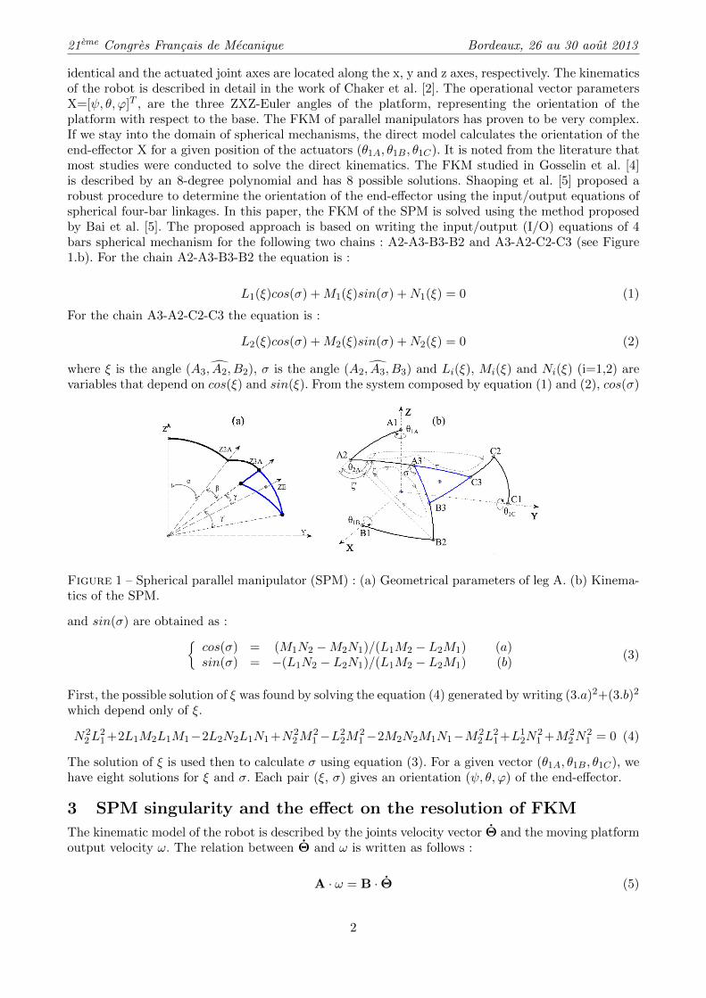
Where, σmax and σmin are the largest and smallest singular value of J, respectively. We adopted in thenext of the representation the inverse of the condition number η = 1/κ(J). For maximum dexterity(η ' 1), the precision of the Jacobian matrix is maximal. For parallel robot, there are two types ofsingularities : serial singularity and parallel singularity. The serial singularity is the singularity on abranch of the parallel robot. It appears when the arm is extended or when it is folded on itself. Itis located on the borders of the workspace as is illustrated by the following Figure 2.b. The parallel
Figure 2 – (a) Serial singularity mapping for SPM in ψ, θ space. (b) parallel singularity area in ψ, θspace.
singularities of SPM are located within the workspace. This region is heavily used in the case of theaimed application, the case of minimally invasive surgery [2]. The parallel singularity appears whenthe three parallel branches K2K3 connected to the effector intersect, for K=A, B and C. An exampleof parallel singularity configuration, a central, is shown in Figure 3.a. The dexterity index distributionof parallel matrix, A, is shown in Figure 2.a. The condition number is calculated for self-rotationϕ = 50◦. The red areas correspond to singular configurations. In Figure 3.b, a variation of platformself-rotation, ϕ, is caused around the central position defined by the vector Zc. As is illustrated, thevariation is not perceived by the joint coordinates : θ1A, θ1B and θ1C . The information provided bythe sensors installed on the actuated joints of the base are the entries of the SPM direct kinematicmodel. If the robot is in singular configuration, then the actual situation of the platform will not beidentified correctly. In the next section, we propose a solution to overcome the problems of FKM whenthe end-effector crosses a singular zone.
3
21eme Congres Francais de Mecanique Bordeaux, 26 au 30 aout 2013
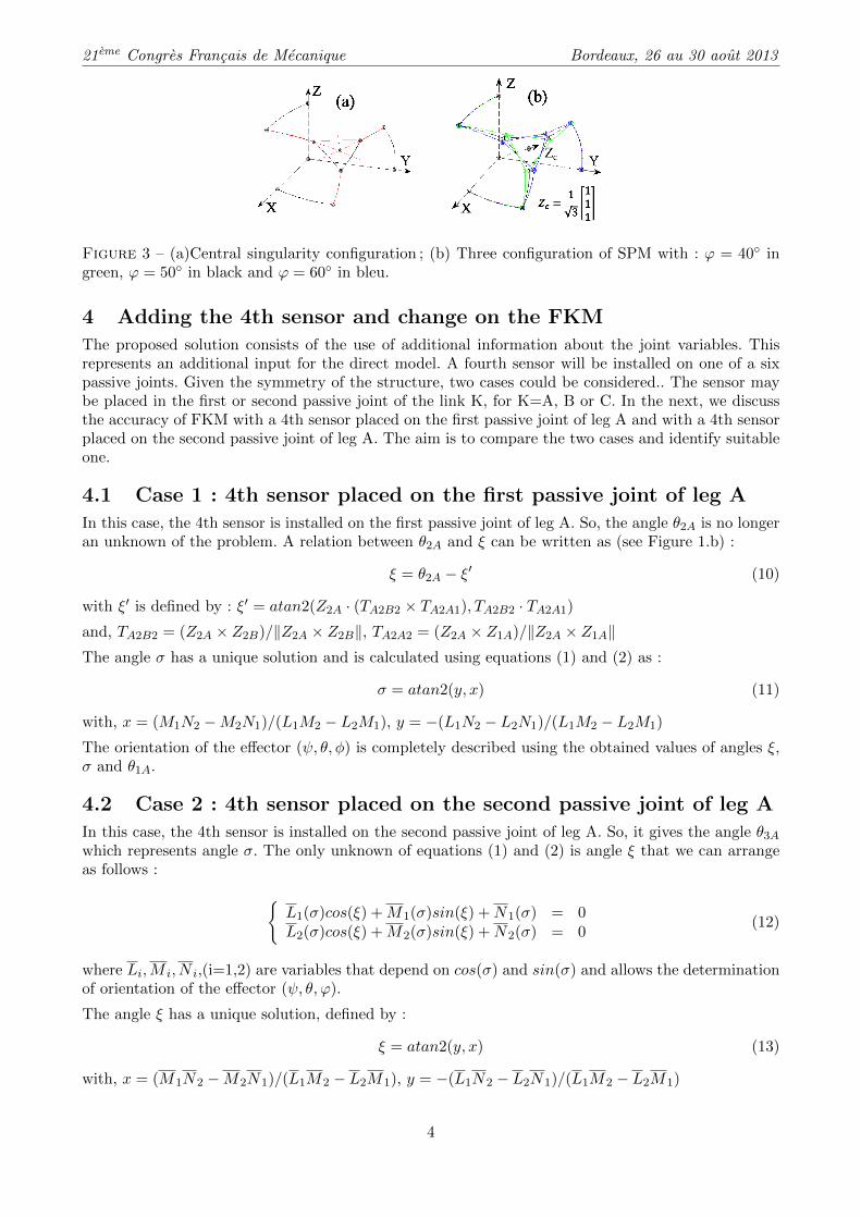
Figure 3 – (a)Central singularity configuration ; (b) Three configuration of SPM with : ϕ = 40◦ ingreen, ϕ = 50◦ in black and ϕ = 60◦ in bleu.
4 Adding the 4th sensor and change on the FKM
The proposed solution consists of the use of additional information about the joint variables. Thisrepresents an additional input for the direct model. A fourth sensor will be installed on one of a sixpassive joints. Given the symmetry of the structure, two cases could be considered.. The sensor maybe placed in the first or second passive joint of the link K, for K=A, B or C. In the next, we discussthe accuracy of FKM with a 4th sensor placed on the first passive joint of leg A and with a 4th sensorplaced on the second passive joint of leg A. The aim is to compare the two cases and identify suitableone.
4.1 Case 1 : 4th sensor placed on the first passive joint of leg A
In this case, the 4th sensor is installed on the first passive joint of leg A. So, the angle θ2A is no longeran unknown of the problem. A relation between θ2A and ξ can be written as (see Figure 1.b) :
ξ = θ2A − ξ′ (10)
with ξ′ is defined by : ξ′ = atan2(Z2A · (TA2B2 × TA2A1), TA2B2 · TA2A1)
and, TA2B2 = (Z2A × Z2B)/‖Z2A × Z2B‖, TA2A2 = (Z2A × Z1A)/‖Z2A × Z1A‖The angle σ has a unique solution and is calculated using equations (1) and (2) as :
σ = atan2(y, x) (11)
with, x = (M1N2 −M2N1)/(L1M2 − L2M1), y = −(L1N2 − L2N1)/(L1M2 − L2M1)
The orientation of the effector (ψ, θ, φ) is completely described using the obtained values of angles ξ,σ and θ1A.
4.2 Case 2 : 4th sensor placed on the second passive joint of leg A
In this case, the 4th sensor is installed on the second passive joint of leg A. So, it gives the angle θ3Awhich represents angle σ. The only unknown of equations (1) and (2) is angle ξ that we can arrangeas follows :
{L1(σ)cos(ξ) +M1(σ)sin(ξ) +N1(σ) = 0L2(σ)cos(ξ) +M2(σ)sin(ξ) +N2(σ) = 0
(12)
where Li,M i, N i,(i=1,2) are variables that depend on cos(σ) and sin(σ) and allows the determinationof orientation of the effector (ψ, θ, ϕ).
The angle ξ has a unique solution, defined by :
ξ = atan2(y, x) (13)
with, x = (M1N2 −M2N1)/(L1M2 − L2M1), y = −(L1N2 − L2N1)/(L1M2 − L2M1)
4
21eme Congres Francais de Mecanique Bordeaux, 26 au 30 aout 2013
4.3 Comparative study
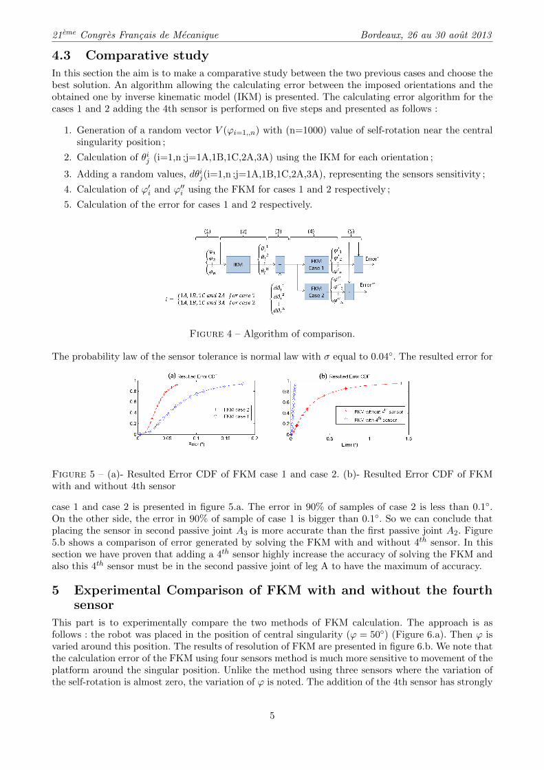
In this section the aim is to make a comparative study between the two previous cases and choose thebest solution. An algorithm allowing the calculating error between the imposed orientations and theobtained one by inverse kinematic model (IKM) is presented. The calculating error algorithm for thecases 1 and 2 adding the 4th sensor is performed on five steps and presented as follows :
1. Generation of a random vector V (ϕi=1,,n) with (n=1000) value of self-rotation near the centralsingularity position ;
2. Calculation of θij (i=1,n ;j=1A,1B,1C,2A,3A) using the IKM for each orientation ;
3. Adding a random values, dθij(i=1,n ;j=1A,1B,1C,2A,3A), representing the sensors sensitivity ;
4. Calculation of ϕ′i and ϕ′′i using the FKM for cases 1 and 2 respectively ;
5. Calculation of the error for cases 1 and 2 respectively.
Figure 4 – Algorithm of comparison.
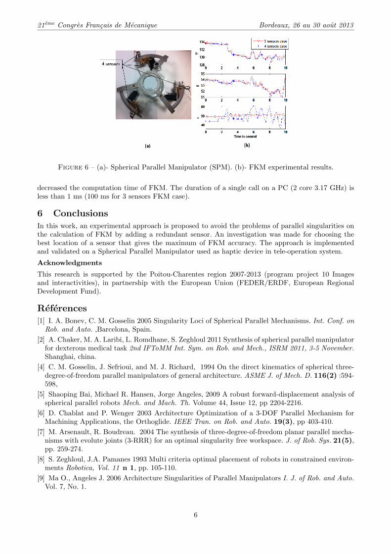
The probability law of the sensor tolerance is normal law with σ equal to 0.04◦. The resulted error for
Figure 5 – (a)- Resulted Error CDF of FKM case 1 and case 2. (b)- Resulted Error CDF of FKMwith and without 4th sensor
case 1 and case 2 is presented in figure 5.a. The error in 90% of samples of case 2 is less than 0.1◦.On the other side, the error in 90% of sample of case 1 is bigger than 0.1◦. So we can conclude thatplacing the sensor in second passive joint A3 is more accurate than the first passive joint A2. Figure5.b shows a comparison of error generated by solving the FKM with and without 4th sensor. In thissection we have proven that adding a 4th sensor highly increase the accuracy of solving the FKM andalso this 4th sensor must be in the second passive joint of leg A to have the maximum of accuracy.
5 Experimental Comparison of FKM with and without the fourthsensor
This part is to experimentally compare the two methods of FKM calculation. The approach is asfollows : the robot was placed in the position of central singularity (ϕ = 50◦) (Figure 6.a). Then ϕ isvaried around this position. The results of resolution of FKM are presented in figure 6.b. We note thatthe calculation error of the FKM using four sensors method is much more sensitive to movement of theplatform around the singular position. Unlike the method using three sensors where the variation ofthe self-rotation is almost zero, the variation of ϕ is noted. The addition of the 4th sensor has strongly
5
21eme Congres Francais de Mecanique Bordeaux, 26 au 30 aout 2013
Figure 6 – (a)- Spherical Parallel Manipulator (SPM). (b)- FKM experimental results.
decreased the computation time of FKM. The duration of a single call on a PC (2 core 3.17 GHz) isless than 1 ms (100 ms for 3 sensors FKM case).
6 ConclusionsIn this work, an experimental approach is proposed to avoid the problems of parallel singularities onthe calculation of FKM by adding a redundant sensor. An investigation was made for choosing thebest location of a sensor that gives the maximum of FKM accuracy. The approach is implementedand validated on a Spherical Parallel Manipulator used as haptic device in tele-operation system.
Acknowledgments
This research is supported by the Poitou-Charentes region 2007-2013 (program project 10 Imagesand interactivities), in partnership with the European Union (FEDER/ERDF, European RegionalDevelopment Fund).
References[1] I. A. Bonev, C. M. Gosselin 2005 Singularity Loci of Spherical Parallel Mechanisms. Int. Conf. on
Rob. and Auto. ,Barcelona, Spain.
[2] A. Chaker, M. A. Laribi, L. Romdhane, S. Zeghloul 2011 Synthesis of spherical parallel manipulatorfor dexterous medical task 2nd IFToMM Int. Sym. on Rob. and Mech., ISRM 2011, 3-5 November.Shanghai, china.
[4] C. M. Gosselin, J. Sefrioui, and M. J. Richard, 1994 On the direct kinematics of spherical three-degree-of-freedom parallel manipulators of general architecture. ASME J. of Mech. D. 116(2) :594-598,
[5] Shaoping Bai, Michael R. Hansen, Jorge Angeles, 2009 A robust forward-displacement analysis ofspherical parallel robots Mech. and Mach. Th. Volume 44, Issue 12, pp 2204-2216.
[6] D. Chablat and P. Wenger 2003 Architecture Optimization of a 3-DOF Parallel Mechanism forMachining Applications, the Orthoglide. IEEE Tran. on Rob. and Auto. 19(3), pp 403-410.
[7] M. Arsenault, R. Boudreau. 2004 The synthesis of three-degree-of-freedom planar parallel mecha-nisms with evolute joints (3-RRR) for an optimal singularity free workspace. J. of Rob. Sys. 21(5),pp. 259-274.
[8] S. Zeghloul, J.A. Pamanes 1993 Multi criteria optimal placement of robots in constrained environ-ments Robotica, Vol. 11 n 1, pp. 105-110.
[9] Ma O., Angeles J. 2006 Architecture Singularities of Parallel Manipulators I. J. of Rob. and Auto.Vol. 7, No. 1.
6
Related Documents


![MEC6503 Industrial Robotics Project 1- Postures for a ...stefan.bracher.info/files/Mec6503_1.pdf · A Fanuc M16iB [1] manipulator is used to deburr the edge point of a spherical block](https://static.cupdf.com/doc/110x72/60f4dd73791bf24c77069e12/mec6503-industrial-robotics-project-1-postures-for-a-a-fanuc-m16ib-1-manipulator.jpg)