1 RESNET/ACCA/ANSI Standard 310 Standard for Grading the Installation of HVAC Systems Forward (Informative) This Standard provides a methodology for evaluating the installation quality of Unitary HVAC systems. It’s comprised of five tasks - a design review, a total duct leakage test, a Blower Fan volumetric airflow test, a Blower Fan watt draw test, and a non-invasive evaluation of refrigerant charge. The five tasks are designed to be completed in sequence. With the completion of each task, the results are evaluated for compliance with specified thresholds. For Task 1, these thresholds are design tolerances. For Tasks 2 through 5, the thresholds are installation quality grades. Furthermore, for Tasks 1 through 3, specified thresholds must be satisfied or the subsequent tasks cannot be completed. A visual representation of the workflow and the diagnostic test methods is shown in Figure 1. Figure 1: Illustration of Workflow and Diagnostic Test Methods In this standard, the terms Townhouse, Dwelling Unit, and Sleeping Unit are interchangeable with the term Dwelling, except where specifically noted. This Standard contains both normative requirements and informative supporting material. The normative requirements must be complied with to conform to the Standard. Informative materials only provide supportive content and are marked as such. 1. Purpose. This standard establishes the procedures, tolerances, and record keeping required to evaluate elements of an HVAC System’s design and installation. 2. Scope. This standard is applicable to Unitary HVAC Systems including air conditioners and heat pumps up to 65 kBtuh and furnaces up to 125 kBtuh in detached one- and two-family Dwellings, Townhouses, as well as in Dwelling Units and Sleeping Units that have their own HVAC system separate from other units. It is intended for use by home energy raters, energy auditors, code officials, or HVAC contractors. 3. Definitions. AHRI Reference Number – The unique identifier assigned by the Air-Conditioning, Heating, & Refrigeration Institute (AHRI) to a specific piece of equipment or combination of equipment that it has certified.

Welcome message from author
This document is posted to help you gain knowledge. Please leave a comment to let me know what you think about it! Share it to your friends and learn new things together.
Transcript
1
RESNET/ACCA/ANSI Standard 310
Standard for Grading the Installation of HVAC Systems
Forward (Informative)
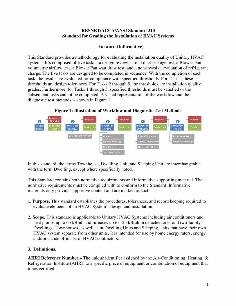
This Standard provides a methodology for evaluating the installation quality of Unitary HVAC
systems. It’s comprised of five tasks - a design review, a total duct leakage test, a Blower Fan
volumetric airflow test, a Blower Fan watt draw test, and a non-invasive evaluation of refrigerant
charge. The five tasks are designed to be completed in sequence. With the completion of each
task, the results are evaluated for compliance with specified thresholds. For Task 1, these
thresholds are design tolerances. For Tasks 2 through 5, the thresholds are installation quality
grades. Furthermore, for Tasks 1 through 3, specified thresholds must be satisfied or the
subsequent tasks cannot be completed. A visual representation of the workflow and the
diagnostic test methods is shown in Figure 1.
Figure 1: Illustration of Workflow and Diagnostic Test Methods
In this standard, the terms Townhouse, Dwelling Unit, and Sleeping Unit are interchangeable
with the term Dwelling, except where specifically noted.
This Standard contains both normative requirements and informative supporting material. The
normative requirements must be complied with to conform to the Standard. Informative
materials only provide supportive content and are marked as such.
1. Purpose. This standard establishes the procedures, tolerances, and record keeping required to
evaluate elements of an HVAC System’s design and installation.
2. Scope. This standard is applicable to Unitary HVAC Systems including air conditioners and
heat pumps up to 65 kBtuh and furnaces up to 125 kBtuh in detached one- and two-family
Dwellings, Townhouses, as well as in Dwelling Units and Sleeping Units that have their own
HVAC system separate from other units. It is intended for use by home energy raters, energy
auditors, code officials, or HVAC contractors.
3. Definitions.
AHRI Reference Number – The unique identifier assigned by the Air-Conditioning, Heating, &
Refrigeration Institute (AHRI) to a specific piece of equipment or combination of equipment that
it has certified.
2
Air Conditioner – A vapor-compression refrigeration device that transfers heat from a location
being cooled to another location using the physical properties of an evaporating and condensing
fluid known as a refrigerant.
Architectural Option – A modification to a portion of an Architectural Plan that may be
optionally used.
Architectural Plan – An architectural drawing defining the room quantity, room type, and
dimensions of a Dwelling.
Bedroom – For one- and two-family Dwellings and Townhouses, a room 1 or space 70 square
feet of floor area or greater, with egress window or skylight, and doorway to the main body of
the Dwelling Unit, that can be used for sleeping. For all other Dwelling Units, a room 2 or space
that can be used for sleeping. For all Dwelling or Sleeping Units, the number of Bedrooms shall
not be less than one.
Blower Fan – The fan inside the equipment of a Forced-Air HVAC System that forces the
heated and/or cooled air to be distributed within a Dwelling.
Boiler – A space-heating appliance with a capacity up to 225 kBtuh in which liquid is heated by
burning fuel or converting electrical energy.
Climate Condition – The classification of a climate, as defined by ACCA Manual S, into
Condition A or B. Condition B represents climates for which the sensible heat ratio is ≥ 0.95 and
the ratio of Heating Degree Days to Cooling Degree Days is ≥ 2.0 3. Climates that do not meet
Condition B are considered to be Condition A.
Condensing Temperature – The refrigerant Saturation Temperature measured at the service
valve at the condenser coil entrance.
Condensing Temperature Over Ambient (CTOA) – A constant value that represents the
difference between the Condensing Temperature and the outdoor air used to cool the refrigerant
in the condenser coil.
Conditioned Floor Area (CFA) 4 – The floor area of the Conditioned Space Volume within a
building or Dwelling Unit, not including the floor area of attics, crawlspaces, and basements
below air sealed and insulated floors. The following specific spaces are addressed to ensure
consistent application of this definition:
• The floor area of a wall assembly that is adjacent to Conditioned Space Volume shall be
included.
1 (Informative Note) A "den," "library," "home office" or other similar rooms with a closet, egress window,
doorway to the main body of the Dwelling Unit, and 70 square feet of floor area or greater are considered a
Bedroom, but living rooms, foyers, and other rooms not intended for sleeping, are not. The number of rooms
identified as Bedrooms is used to determine the number of occupants. 2 (Informative Note) Informative Annex A of Standard ANSI/RESNET/ICC 380 contains a table that summarizes parts
of a Dwelling Unit that are included in Conditioned Floor Area. 3 (Informative Note) ACCA uses a base temperature of 65 °F (18 °C) for heating and 50 °F (10 °C) for cooling. 4 (Informative Note) Informative Annex A of Standard ANSI/RESNET/ICC 380 contains a table that summarizes parts
of a Dwelling Unit that are included in Conditioned Floor Area.
3
• The floor area of a basement shall be included if the party conducting the evaluation has
either:
o Obtained an ACCA Manual J, S, and either B or D report and verified that both
the heating and cooling equipment and distribution system are designed to offset
the entire design load of the volume, or,
o Verified through visual inspection that both the heating and cooling equipment
and distribution system serve the volume and, in the judgement of the party
conducting evaluations, are capable of maintaining the heating and cooling
temperatures specified by the Thermostat section in Table 4.2.2(1) in
ANSI/RESNET/ICC 301.
• The floor area of a garage shall be excluded, even when it is conditioned.
• The floor area of a thermally isolated sunroom shall be excluded.
• The floor area of an attic shall be excluded, even when it is Conditioned Space Volume.
• The floor area of a crawlspace shall be excluded, even when it is Conditioned Space
Volume.
Conditioned Space Volume 4 - The volume within a Dwelling Unit serviced by a space heating
or cooling system designed to maintain space conditions at 78 °F (26 °C) for cooling and 68 °F
(20 °C) for heating. The following specific spaces are addressed to ensure consistent application
of this definition:
• If the volume both above and below a floor assembly meets this definition and is part
of the Rated Dwelling Unit, then the volume of the floor assembly shall also be
included. Otherwise the volume of the floor assembly shall be excluded.
o Exception: The wall height shall extend from the finished floor to the bottom side
of the floor decking above the Rated Dwelling Unit for non-top floor level
Dwelling Units and to the exterior enclosure air barrier for top floor level
Dwelling Units.
• If the volume of at least one of the spaces horizontally adjacent to a wall assembly
meets this definition, and that volume is part of the Rated Dwelling Unit, then the
volume of the wall assembly shall also be included. Otherwise, the volume of the wall
assembly shall be excluded.
o Exception: If the volume of one of the spaces horizontally adjacent to a wall
assembly is a Dwelling Unit other than the Rated Dwelling Unit, then the volume
of that wall assembly shall be evenly divided between both adjacent Dwelling
Units.
• The volume of an attic that is not both air sealed and insulated at the roof deck shall
be excluded.
• The volume of a vented crawlspace shall be excluded.
• The volume of a garage shall be excluded, even when it is conditioned.
• The volume of a thermally isolated sunroom shall be excluded.
• The volume of an attic that is both air sealed and insulated at the roof deck, the
volume of an unvented crawlspace, and the volume of a basement shall only be
included if the volume is contiguous with the Rated Dwelling Unit and the party
conducting evaluations has either:
4
o Obtained an ACCA Manual J, S, and either B or D report and verified that
both the heating and cooling equipment and distribution system are designed
to offset the entire design load of the volume, or,
o Verified through visual inspection that both the heating and cooling
equipment and distribution system serve the volume and, in the judgement of
the party conducting evaluations, are capable of maintaining the heating and
cooling temperatures specified by the Thermostat section in Table 4.2.2(1).
• The volume of a mechanical closet, regardless of access location, that is contiguous
with the Rated Dwelling Unit shall be included if:
o it is serviced by a space heating or cooling system designed to maintain space
conditions at 78 °F (26 °C) for cooling and 68 °F (20 °C) for heating, and
o it only includes equipment serving the Rated Dwelling Unit, and
o the mechanical room is not intentionally air sealed from the Rated Dwelling Unit.
Design Temperature Difference (DTD) – A constant value that represents the difference
between the evaporator coil refrigerant’s Saturation Temperature and the supply air temperature.
Dwelling – Any building that contains one or two Dwelling Units used, intended, or designed to
be built, used, rented, leased, let or hired out to be occupied, or that are occupied for living
purposes.
Dwelling Unit - A single unit providing complete independent living facilities for one or more
persons, including permanent provisions for living, sleeping, eating, cooking, and sanitation.
Dwelling-Unit Mechanical Ventilation System – A Ventilation system consisting of powered
Ventilation equipment such as motor-driven fans and blowers and related mechanical
components such as ducts, inlets, dampers, filters and associated control devices that provides
Dwelling-Unit Ventilation at a known or measured airflow rate.
Egress Window – An operable window that provides for a means of escape and access for
rescue in the event of an emergency and with the following attributes:
• Has a sill height of not more than 44 inches above the floor; and,
• Has a minimum net clear opening of 5.7 sq. ft.; and,
• Has a minimum net clear opening height of 24 in.; and,
• Has a minimum net clear opening width of 20 in.; and,
• Is operational from the inside of the room without the use of keys, tools or special
knowledge.
Forced-Air HVAC System – A type of HVAC System that incorporates a Blower Fan to move
conditioned air.
Front Orientation – The direction that the front door of a Dwelling is facing.
Furnace – A space-heating appliance in which air is heated by burning fuel or converting
electrical energy.
Heat Pump – A vapor-compression refrigeration device that includes a reversing valve and
optimized heat exchangers so that the direction of heat flow is reversed in order to transfer heat
5
from one location to another using the physical properties of an evaporating and condensing fluid
known as a refrigerant.
HVAC System – Cooling-only, heating-only, or combined cooling-heating equipment, including
any supply and/or return distribution systems.
Independent Verification Report – A report provided by a party operating under a third-party
quality control program.
Mini-Split Air Conditioner (MNAC) – An Air Conditioner that has variable refrigerant flow
and distributed refrigerant technology with a single outdoor section serving a single indoor
section. The indoor section is typically, but not exclusively, mounted on walls and designed to
condition air either directly or through limited duct runs, though duct length is not a determinant
for meeting this definition.
Mini-Split Heat Pump (MNHP) – A Heat Pump that has variable refrigerant flow and
distributed refrigerant technology with a single outdoor section serving a single indoor section.
The indoor section is typically, but not exclusively, mounted on walls and designed to condition
air either directly or through limited duct runs, though duct length is not a determinant for
meeting this definition.
Multi-Split Air Conditioner (MTAC) – An Air Conditioner that has variable refrigerant flow
and distributed refrigerant technology with the capability of serving multiple indoor sections
with a single outdoor section. The indoor sections are typically, but not exclusively, mounted on
room walls and designed to condition air either directly or through limited duct runs, though duct
length is not a determinant meeting this definition.
Multi-Split Heat Pump (MTHP) – A Heat Pump that has variable refrigerant flow and
distributed refrigerant technology with the capability of serving multiple indoor sections with a
single outdoor section. The indoor sections are typically, but not exclusively, mounted on room
walls and designed to condition air either directly or through limited duct runs, though duct
length is not a determinant meeting this definition.
OEM Static Pressure Table – Documentation produced by a Forced-Air HVAC System
equipment manufacturer that indicates the Blower Fan airflow at specified fan-speed settings,
static pressure values, and in some instances voltage.
Other Equipment Type – Any HVAC equipment type that is not an Air Conditioner, Boiler,
Furnace, or Heat Pump.
Other Motor Type – Any Blower Fan motor type that is not a Permanent Split Capacitor (PSC)
or Electronically Commutated Motor (ECM).
Other Ventilation Standard – Any ventilation standard that is not ASHRAE 62.2-2010,
ASHRAE 62.2-20103, or ASHRAE 62.2-2016.
Saturation Temperature – The temperature at which the refrigerant undergoes a phase change
in either the condenser or evaporator coils.
6
Sleeping Unit – A room or space in which people sleep, which can also include permanent
provisions for living, eating, and either sanitation or kitchen facilities but not both. Such rooms
and spaces that are also part of a Dwelling Unit are not Sleeping Units.
Target Liquid Line Temperature – The calculated target temperature of the liquid line.
Target Subcooling – The manufacturer prescribed subcooling for the equipment being tested.
Target Suction Line Temperature – The calculated target temperature of the suction line.
Target Superheat – The manufacturer prescribed superheat for the equipment being tested.
Townhouse – A single-family Dwelling Unit constructed in a group of three or more attached
units in which each unit extends from the foundation to roof and with open space on at least two
sides.
Unconditioned Space Volume 5 – The volume within a building or Dwelling Unit that is not
Conditioned Space Volume but which contains heat sources or sinks that influence the
temperature of the area or room. The following specific spaces are addressed to ensure consistent
application of this definition:
• If either one or both of the volumes above and below a floor assembly is
Unconditioned Space Volume, then the volume of the floor assembly shall be
included.
• If the volume of both of the spaces horizontally adjacent to a wall assembly are
Unconditioned Space Volume, then the volume of the wall assembly shall be
included.
• The volume of an attic that is not both air sealed and insulated at the roof deck shall
be included.
• The volume of a vented crawlspace shall be included.
• The volume of a garage shall be included, even when it is conditioned.
• The volume of a thermally isolated sunroom shall be included.
• The volume of an attic that is both air sealed and insulated at the roof deck, the
volume of an unvented crawlspace, and the volume of a basement shall be included
unless it meets the definition of Conditioned Space Volume.
Unitary – One or more factory-made assemblies which normally may include an evaporator or
cooling coil, a compressor and condenser combination, and may include a heating function. The
equipment can be ducted or ductless; it can be a split-system or single package.
Ventilation - The process of providing outdoor air directly to a Dwelling by natural or
mechanical means. Such air may or may not be conditioned.
Ventilation Mode – For a Ventilation system that uses the Blower Fan of the Forced-Air HVAC
System, the Blower Fan setting used to provide Dwelling-Unit Ventilation rather than the
settings to maintain temperature setpoints.
5 (Informative Note) Informative Annex A of Standard ANSI/RESNET/ICC 380 contains a table that summarizes parts
of a Dwelling Unit that are included in Unconditioned Space Volume.
7
4. Task 1: Evaluation of the Design.
4.1. Overview. This procedure shall be completed by first collecting the design information
specified in Section 4.2, then verifying that all required information has been provided
and falls within the tolerances specified in Section 4.3.
4.2. Required Design Information. The following design information shall be collected by
the person completing the evaluation for the Dwelling to be rated.
4.2.1. Architectural design documentation, consisting of the following:
4.2.1.1. The Architectural Plan
4.2.1.2. Any Architectural Options for the Plan.
4.2.2. HVAC design overview, consisting of the following:
4.2.2.1. The designer name.
4.2.2.2. The designer company.
4.2.2.3. The date of design.
4.2.2.4. The architectural scope of the HVAC design, consisting of the following:
4.2.2.4.1. If a Dwelling or Townhouse, or a Dwelling Unit or Sleeping Unit within:
4.2.2.4.1.1. The name of the Architectural Plan that the HVAC design is based on
or the unique address of the building.
4.2.2.4.1.2. Any Architectural Option(s) used in the HVAC design, and a list of
other Architectural Option(s), if any, that the design can be used with.
4.2.2.4.2. If a Dwelling Unit or Sleeping Unit not within a Dwelling or Townhouse:
4.2.2.4.2.1. A unique identifier for the building that the unit is within 6.
4.2.2.4.2.2. The name of the Architectural Plan that the HVAC design is based on,
and a list of other Architectural Plan(s), if any, that the design can be used
with.
4.2.2.4.2.3. Any Architectural Option(s) used in the HVAC design, and a list of
other Architectural Option(s), if any, that the design can be used with.
4.2.2.5. If a software program was used to complete the design, the software program
name and version that was used.
4.2.3. Dwelling-Unit Mechanical Ventilation System design for each system that serves the
Dwelling to be rated, consisting of the following:
4.2.3.1. A unique name or identifier for the system 7.
4.2.3.2. The specified system type: supply, exhaust, balanced without recovery, ERV, or
HRV.
6 (Informative Note) For example, the name of the development or the building’s address. 7 (Informative Note) For example, “Bath Fan 1”, “ERV 1”.
8
4.2.3.3. The specified control location for the system 8.
4.2.3.4. For systems serving Dwelling Units or Sleeping Units not within a Dwelling or
Townhouse:
4.2.3.4.1. The specified system manufacturer and model number.
4.2.3.4.2. The unit(s) served by the system.
4.2.3.5. The name of the Ventilation zone(s) 9 served by the system.
4.2.3.6. An overview of each Ventilation zone that the system serves, consisting of the
following information.
4.2.3.6.1. The design basis for the Ventilation airflow rate and run-time for the
Ventilation zone: ASHRAE 62.2-2010, ASHRAE 62.2-2013, or ASHRAE 62.2-
2016, or Other Ventilation Standard.
4.2.3.6.2. The number of Bedrooms within the Ventilation zone.
4.2.3.6.3. The floor area of the Ventilation zone.
4.2.3.6.4. The design’s Ventilation airflow rate, runtime per cycle, and cycle time for
the Ventilation zone.
4.2.3.6.5. The design’s time-averaged Ventilation airflow rate for the Ventilation
zone, calculated using Equation 1.
����_������ ��� ��� = ��� ��� × ������� ��� ���������� ���� (1)
Where:
Time_Averaged Vent Rate = The average Ventilation airflow rate.
Vent Rate = The design’s Ventilation airflow rate reported in Section 4.2.3.6.4.
Runtime Per Cycle = The runtime per cycle reported in Section 4.2.3.6.4.
Cycle Time = The cycle time reported in Section 4.2.3.6.4.
4.2.4. Heat gain and heat loss loads for each heated or cooled zone in the Dwelling to be
rated, consisting of the following:
4.2.4.1. The name of the heated or cooled zone 10.
4.2.4.2. For Dwelling Units and Sleeping Units not within a Dwelling or Townhouse,
the unit’s location:
4.2.4.2.1. The top floor, mid-level floor, or bottom floor of the building, and,
4.2.4.2.2. Either a corner unit or middle unit that is between two other units.
8 (Informative Note) Examples of common locations include bathroom or utility room. 9 (Informative Note) Examples of Ventilation zones include Whole Dwelling, Upper Level, Lower Level, Basement. 10 (Informative Note) Examples of heated or cooled zones include Upper Level, Master Suite, Basement.
9
4.2.4.3. The design basis for the heat gain and heat loss loads: ACCA Manual J v8,
2013; ACCA Manual J v8, 2016; 2017 ASHRAE Fundamentals; or per the
Authority Having Jurisdiction.
4.2.4.4. Whether the loads for the zone were calculated room-by-room or as a single
block.
4.2.4.5. The indoor heating design temperature and indoor cooling design temperature
used.
4.2.4.6. The outdoor heating design temperature and outdoor cooling design
temperature used. If located in the United States, then also the county and state,
or U.S. territory, that the design was completed for.
4.2.4.7. The number of occupants in the zone.
4.2.4.8. The total occupant internal gains in the zone.
4.2.4.9. The total non-occupant internal gains in the zone.
4.2.4.10. The Conditioned Floor Area of the zone.
4.2.4.11. The window area of the zone.
4.2.4.12. The solar heat gain coefficient value used in the greatest amount of window
area in the zone.
4.2.4.13. The nominal R-value of the insulation 11 used in the greatest amount of above-
grade wall area in the zone.
4.2.4.14. The nominal R-value of the insulation used in the greatest amount of ceiling
area in the zone.
4.2.4.15. The infiltration rate of the zone.
4.2.4.16. The time-averaged mechanical Ventilation airflow rate of the zone.
4.2.4.17. The calculated sensible, latent, and total heat gain at design conditions for one
or more orientations for the zone.
4.2.4.18. The difference between the maximum and minimum total heat gain at design
conditions across the orientations specified in Section 4.2.4.17.
4.2.4.19. The calculated total heat loss at design conditions of the zone.
4.2.5. Specifications for all HVAC Systems serving the Dwelling to be rated, consisting of
the following for each HVAC System:
4.2.5.1. A unique name or identifier for the HVAC system.
4.2.5.2. The name of the heated or cooled zone(s) 12 that the HVAC system serves.
4.2.5.3. An equipment overview, consisting of the following for each piece of
equipment:
11 (Informative Note) If both cavity and continuous insulation are used, the nominal R-value equals the sum of
nominal R-value of the cavity and continuous insulation. 12 (Informative Note) Examples of zones include Whole Dwelling, Upper Level, Lower Level, Basement.
10
4.2.5.3.1. The equipment type: Air Conditioner, Boiler, Furnace, Heat Pump, or
Other Equipment Type.
4.2.5.3.2. The equipment manufacturer(s) and model number(s) 13.
4.2.5.3.3. The AHRI Reference Number of the equipment or if an AHRI Reference
Number is not available, OEM-provided documentation shall be collected with
the rated efficiency of the equipment. If the equipment contains multiple
components, the rated efficiency shall reflect the specific combination of indoor
and outdoor components, along with confirmation from the OEM that the two
components are designed to be used together.
4.2.5.3.4. If the equipment type is an Air Conditioner, Furnace, or Heat Pump, then
the Blower Fan motor type: Permanent Split Capacitor (PSC), Electronically
Commutated Motor (ECM), or Other Motor Type.
4.2.5.3.5. If the equipment type is an Air Conditioner, Furnace, or Heat Pump, then
the Blower Fan speed type: single-speed, two-speed, or variable-speed 14.
4.2.5.3.6. If the equipment type is an Air Conditioner or Heat Pump, then the
compressor speed type: single-speed, two-speed, or variable-speed.
4.2.5.3.7. If the equipment type is an Air Conditioner or Heat Pump, then whether it
is also a Mini-Split Air Conditioner, Mini-Split Heat Pump, Multi-Split Air
Conditioner, or Multi-Split Heat Pump.
4.2.5.3.8. If the equipment type is a Heat Pump, then the ratio of its maximum rated
capacity relative to its minimum rated capacity.
4.2.5.3.9. If the equipment type is an Air Conditioner or Heat Pump, then:
4.2.5.3.9.1. The metering device type: piston or capillary tube, Thermal
Expansion Value (TXV), or Electronic Expansion Valve (EEV).
4.2.5.3.9.2. If the metering device type in Section 4.2.5.3.9.1 is TXV or EEV,
then the OEM-specified subcooling target at the service valve.
4.2.5.3.10. If the equipment type is an Air Conditioner or Heat Pump, then the
equipment’s rated cooling efficiency 15.
4.2.5.3.11. If the equipment type is an Air Conditioner or Heat Pump, then the latent,
sensible, and total cooling capacity of the equipment at design conditions, from
OEM expanded performance data.
13 (Informative Note) For equipment types that include both an evaporator/fan-coil and a condenser, include the
manufacturer and model number for both components. 14 (Informative Note) While equipment typically has multiple speed settings to select from during installation, this
parameter is related to the number of operational speeds that the system is capable of. Single-speed indicates a
system that operates at no more than one speed setting each for heating mode and cooling mode. Two-speed
indicates a system that can operate at no more than two speeds each for heating mode and cooling mode.
Variable-speed indicates a system that can operate at more than two speeds. 15 (Informative Note) For example, if the metric for the rated efficiency of the equipment is SEER, then its SEER
rating shall be reported; if the metric is EER, then its EER rating shall be reported; if both SEER and EEER, then both
rated values shall be reported.
11
4.2.5.3.12. If the equipment type is an Air Conditioner or Heat Pump, then the
Cooling Sizing Percentage, calculated using Equation 2:
������ ����� �������� = ���� ������ ���������� ��� ��� (2)
Where:
Total Cooling Capacity = The total cooling capacity of the specified equipment
at design conditions, as reported in Section 4.2.5.3.11.
Total Heat Gain = The maximum total heat gain among the specified
orientations reported in Section 4.2.4.17.
4.2.5.3.13. If the equipment type is a Heat Pump, then the Climate Condition, either
A or B.
4.2.5.3.14. If a Condition B Climate is reported in Section 4.2.5.3.13, then the
Sensible Heat Ratio shall be calculated and reported using Equation 3:
����� �� ��� ���� = ����� �� ������ !������ ������ !�� (3)
Where:
Sensible Cooling Load = The sensible cooling load of the maximum total
cooling load among the specified orientations reported in Section 4.2.4.17.
Total Cooling Load = The maximum total cooling load among the specified
orientations reported in Section 4.2.4.17.
4.2.5.3.15. If a Condition B Climate is reported in Section 4.2.5.3.13 and the
Dwelling to be rated is located in the United States, then the HDD65/CDD50 Ratio,
as determined using Appendix A for the county and state, or U.S. territory,
reported in Section 4.2.4.6.
4.2.5.3.16. If the equipment type is a Boiler, Furnace, or Heat Pump, then the
equipment’s rated heating efficiency.
4.2.5.3.17. If the equipment type is a Boiler or Furnace, then the heating capacity
type: single-stage, two-stage, or modulating.
4.2.5.3.18. If the equipment type is a Heat Pump, then the heating capacity at 17 °F
(-8 °C) and 47 °F (8 °C).
4.2.5.3.19. If the equipment type is a Boiler or Furnace, then the heating output
capacity.
4.2.5.3.20. If the equipment type is a Boiler or Furnace, then the Heating Sizing
Percentage, calculated using the Equation 4:
12
����� ����� �������� = ����� "����� ���������� ��� !��� (4)
Where:
Heating Output Capacity = The heating output capacity of the specified
equipment, as reported in Section 4.2.5.3.19 16.
Total Heat Loss = The total heat loss reported in Section 4.2.4.19.
4.2.5.3.21. If the equipment type is a Boiler or Furnace, then the venting type, either
natural draft, mechanically drafted, or direct vented.
4.2.5.4. The specified performance rating and metric 17 of the filter, if one or more will
be installed.
4.2.5.5. A duct system design overview, if a duct system will be installed, consisting of
the following:
4.2.5.5.1. The design Blower Fan airflow, expressed in cubic feet per minute or
cubic meters per second of air with a density of 0.075 pounds per cubic feet
(1.201 kg per cubic meter) 18:
4.2.5.5.1.1. In cooling mode if the equipment type is an Air Conditioner or Heat
Pump.
4.2.5.5.1.2. In heating mode if the equipment type is a Furnace or Heat Pump.
4.2.5.5.2. The design Blower Fan speed setting 19:
4.2.5.5.2.1. In cooling mode if the equipment type is an Air Conditioner or Heat
Pump.
4.2.5.5.2.2. In heating mode if the equipment type is a Furnace or Heat Pump.
4.2.5.5.3. The design external static pressure 20.
4.2.5.5.4. The individual room-by-room names and design airflows and the sum of
the design airflows across all rooms.
4.3. Evaluation of Design Information. The design documentation collected in Section 4.2
shall be reviewed to verify that all required information has been provided. In addition,
16 (Informative Note) For two-stage or modulating equipment, the heating output capacity represents the highest
rated output of the equipment. 17 (Informative Note) For example, MERV or FPR. 18 (Informative Note) Airflow at this air density is often referred to as Standard CFM (SCFM) or Standard CMS
(SCMS) and represents air at 68°F, 50% relative humidity, and at a barometric pressure of 29.92" Hg. 19 (Informative Note) This is the OEM setting that corresponds with the design Blower Fan airflow. Common
examples include low, medium-low, medium, medium-high, and high, but also may be defined in terms of dip-
switch settings or other classifications. 20 (Informative Note) This is the sum of the supply-side and return-side static pressure, corresponding to the mode
with the higher design Blower Fan airflow.
13
the Dwelling to be rated 21 shall be compared to the design documentation to verify that
the following criteria have been met.
4.3.1. If a Dwelling or Townhouse, or Dwelling Unit or Sleeping Unit within, is to be
rated, then the following criteria shall be met in addition to the criteria in Section
4.3.4:
4.3.1.1. The name of the Architectural Plan or unique address of the Dwelling to be
rated matches that used in the HVAC design, as documented in Section
4.2.2.4.1.1.
4.3.1.2. Any Architectural Option(s) used in the Dwelling to be rated match those used
in the HVAC design or are in the list of option(s) that the design can be used
with, as documented in Section 4.2.2.4.1.2.
4.3.1.3. The Conditioned Floor Area of each zone in the Dwelling to be rated is between
300 square feet smaller and 100 square feet larger than the area in the HVAC
design, as documented in Section 4.2.4.10.
4.3.1.4. The window area of each zone in the Dwelling to be rated is between 60 square
feet smaller and 15 square feet larger than the area in the HVAC Design, as
documented in Section 4.2.4.11, or for zones with > 500 square feet of window
area, between 12% smaller and 3% larger.
4.3.1.5. The Front Orientation of the Dwelling to be rated matches one of the
orientations included in the orientation-specific heat gains documented in
Section 4.2.4.17.
4.3.1.6. The difference between the maximum and minimum total heat gain for each
zone, as documented in Section 4.2.4.18, is ≤ 6 kBtuh.
4.3.1.7. The heating and cooling loads have been calculated room-by-room, as
documented in Section 4.2.4.4.
4.3.2. If a Dwelling Unit or Sleeping Unit not within a Dwelling or Townhouse is to be
rated, and the maximum total heat gain across orientations documented in Section
4.2.4.17 is ≤18 kBTUh, then the following criteria shall be met in addition to the
criteria in Section 4.3.4:
4.3.2.1. The name of the unique identifier for the building that the unit is within
matches that used in the HVAC design, as documented in Section 4.2.2.4.2.1.
4.3.2.2. The name of the Architectural Plan of the unit to be rated meets one of the
following conditions:
4.3.2.2.1. Matches that used in the HVAC design, as documented in Section
4.2.2.4.2.2.
4.3.2.2.2. Is included in the list of Architectural Plans that the HVAC design can be
used with, as documented in Section 4.2.2.4.2.2, and the Architectural Plan used
21 (Normative Note) While an initial review may be completed prior to construction, ultimately the Dwelling as
constructed shall be compared to the design documentation to verify that the criteria have been met.
14
in the HVAC design has the largest Conditioned Floor Area among the plans
listed.
4.3.2.3. Any Architectural Option(s) used in the unit to be rated meets one of the
following conditions:
4.3.2.3.1. Match those used in the HVAC design, as documented in Section
4.2.2.4.2.3.
4.3.2.3.2. Are included in the list of Architectural Options that the HVAC design can
be used with, as documented in Section 4.2.2.4.2.3, and the Architectural Options
used in the HVAC design have the largest Conditioned Floor Area among the
options listed.
4.3.2.4. The window area of each zone in the Dwelling Unit or Sleeping Unit to be rated
is less than or equal to the area in the HVAC Design, as documented in Section
4.2.4.11.
4.3.2.5. The location of the unit to be rated meets one of the following conditions:
4.3.2.5.1. Matches that used in the HVAC design, as documented in Section 4.2.4.2 22.
4.3.2.5.2. The unit location, as documented in Section 4.2.4.2, is the top floor and a
corner unit.
4.3.2.6. Orientation-specific total heat gains have been documented for all eight
orientations in Section 4.2.4.17.
4.3.3. If a Dwelling Unit or Sleeping Unit not within a Dwelling or Townhouse is to be
rated, and the maximum total heat gain across orientations documented in Section
4.2.4.17 is >18 kBTUh, then the following criteria shall be met in addition to the
criteria in Section 4.3.4:
4.3.3.1. The name of the unique identifier for the building that the unit is within
matches that used in the HVAC design, as documented in Section 4.2.2.4.2.1.
4.3.3.2. The name of the Architectural Plan of the unit to be rated matches that used in
the HVAC design, as documented in Section 4.2.2.4.2.2.
4.3.3.3. Any Architectural Option(s) used in the unit to be rated match those used in the
HVAC design or are included in the list of Architectural Option(s) that the
design can be used with, as documented in Section 4.2.2.4.2.3.
4.3.3.4. The Conditioned Floor Area of each zone in the Dwelling Unit or Sleeping Unit
to be rated is between 300 square feet smaller and 100 square feet larger than
the area in the HVAC design, as documented in Section 4.2.4.10.
4.3.3.5. The window area of each zone in the Dwelling Unit or Sleeping Unit to be rated
is between 60 square feet smaller and 15 square feet larger than the area in the
22 (Normative Note) The top floor, middle floor, or bottom floor and whether the unit is a corner unit or middle
unit.
15
HVAC Design, as documented in Section 4.2.4.11, or for zones with > 500
square feet of window area, between 12% smaller and 3% larger.
4.3.3.6. The Front Orientation of the Dwelling Unit or Sleeping Unit to be rated
matches one of the orientations included in the orientation-specific heat gains
documented in Section 4.2.4.17.
4.3.3.7. The difference between the maximum and minimum total heat gain for each
zone, as documented in Section 4.2.4.18, is ≤ 6 kBtuh.
4.3.4. For all Dwellings, Townhouses, Dwelling Units, and Sleeping Units, the following
criteria shall be met:
4.3.5. The indoor design temperatures used in the loads, as documented in Section
4.2.4.5, equals 70 °F (21 °C) for the heating season and 75 °F (24 °C) for the
cooling season.
4.3.6. If the Dwelling to be rated is located in the U.S., then the cooling season and
heating season outdoor design temperatures used in the loads, as documented in
Section 4.2.4.6, shall not exceed the limits defined in Appendix A.
4.3.7. The number of occupants in the Dwelling to be rated, which shall be calculated
using Equation 5, are within ± 2 of the sum of the occupants used in the loads
across all zones, as documented in Section 4.2.4.7.
"������� = #�� �� �$ %������� + 1 (5)
4.3.8. The solar heat gain coefficient value used in the greatest amount of window area
for each zone in the Dwelling to be rated is within ± 0.1 of the value used in the
loads, as documented in Section 4.2.4.12.
4.3.9. The nominal R-value of the insulation 23 used in the greatest amount of above-
grade wall area for each zone in the Dwelling to be rated is within ± R-2 of the
value used in the loads, as documented in Section 4.2.4.13.
4.3.10. The nominal R-value of the insulation used in the greatest amount of ceiling area
for each zone in the Dwelling to be rated is within ± R-4 of the value used in the
loads, as documented in Section 4.2.4.14.
4.3.11. The infiltration rate of the Dwelling to be rated is within ± 2.0 ACH50 of the
value used in the loads for each zone, as documented in Section 4.2.4.15.
4.3.12. The sum of the design’s time-averaged mechanical Ventilation airflow rates
across all Ventilation zones, as documented in Section 4.2.3.6.5, equals the sum
used in the loads across all heated and cooled zones, as documented in Section
4.2.4.16.
4.3.13. Each HVAC System in the Dwelling to be rated serves the heated or cooled
zone(s) documented in Section 4.2.5.2 24.
23 (Informative Note) If both cavity and continuous insulation are used, the nominal R-value equals the sum of
nominal R-value of the cavity and continuous insulation. 24 (Informative Note) For example, if the design indicates that System A is intended to serve the “Upper Level”
zone, then it shall be verified that System A does serve this zone.
16
4.3.14. Each HVAC System in the Dwelling to be rated matches the equipment type
specified in Section 4.2.5.3.1.
4.3.15. For Air Conditioner and Heat Pump equipment, the Cooling Sizing Percentage,
calculated using Equation 2, matches the Cooling Sizing Percentage value reported
in Section 4.2.5.3.12.
4.3.16. For Boiler and Furnace equipment, the Heating Sizing Percentage, calculated
using Equation 4, matches the Heating Sizing Percentage value reported in Section
4.2.5.3.20.
4.3.17. For Heat Pump equipment, if Climate Condition B is reported in Section
4.2.5.3.13, then the Sensible Heat Ratio, calculated using Equation 3, is ≥ 95% and
the HDD65/CDD50 Ratio, as determined using Appendix A for the county and state,
or U.S. territory, reported in Section 4.2.4.6 is ≥ 2.0.
4.3.18. The sum of the design airflows across all rooms reported in Section 4.2.5.5.4
equals the mode with the higher design Blower Fan airflow, as reported in Section
4.2.5.5.1.
5. Task 2: Evaluation of the Total Duct Leakage.
5.1. Overview. This procedure shall be completed by first meeting the prerequisites in
Section 5.2, then measuring the total duct leakage per Section 5.3, and finally designating
the total duct leakage grade per Section 5.4.
As an alternative to measuring the total duct leakage per Section 5.3, if an Independent
Verification Report is obtained containing the measured total duct leakage of the Forced-
Air HVAC System under test, and the report is approved for use by an entity adopting
and requiring the use of this Standard, then the reported value shall be permitted to be
used.
If an Independent Verification Report is obtained, the reported value shall be used to
designate the total duct leakage grade per Section 5.4.
5.2. Prerequisites. The HVAC design of the Dwelling to be rated shall have been evaluated
in accordance with Section 4: all the required design documentation defined in Section 4.2
shall have been collected, and shall have been reviewed and verified to be in accordance
with Section 4.3. If the design has not been evaluated, then the total duct leakage shall not
be evaluated.
5.3. Procedure to Measure Total Duct Leakage. The total duct leakage of the Forced-Air
HVAC system under test shall be measured in accordance with ANSI/RESNET/ICC 380
and recorded. Exception: If the total amount of supply ductwork or distribution building
cavities does not exceed 10 ft. in length and is entirely in Conditioned Space Volume,
then measurement of total duct leakage is not required 25.
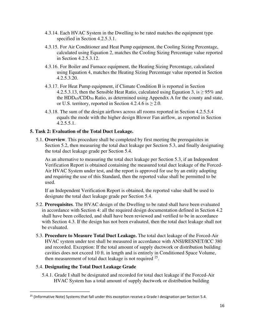
5.4. Designating the Total Duct Leakage Grade
5.4.1. Grade I shall be designated and recorded for total duct leakage if the Forced-Air
HVAC System has a total amount of supply ductwork or distribution building
25 (Informative Note) Systems that fall under this exception receive a Grade I designation per Section 5.4.
17
cavities that does not exceed 10 ft. in length and is entirely in Conditioned Space
Volume, or if the total leakage does not exceed the limits in Table 1a or Table 1b. As
an alternative, if the total duct leakage does not exceed the limits specified within
ANSI/ACCA QI 5 Section 5.1.1a, then Grade I shall also be designated.
Table 1a – Duct Leakage Limits for Grade I (IP)
Time of
Test
# of
Returns
Leakage Limit
(CFM at 25 Pa)
Rough-In < 3 The greater of ≤ 4 per 100 ft2 of CFA or ≤ 40
Rough-In ≥ 3 The greater of ≤ 6 per 100 ft2 of CFA or ≤ 60
Final < 3 The greater of ≤ 8 per 100 ft2 of CFA or ≤ 80
Final ≥ 3 The greater of ≤ 12 per 100 ft2 of CFA or ≤ 120
Table 1b – Duct Leakage Limits for Grade I (SI)
Time of
Test
# of
Returns
Leakage Limit
(CMS at 0.001 IWC)
Rough-In < 3 The greater of ≤ 0.0019 per 9.29 m2 of CFA or ≤ 0.019
Rough-In ≥ 3 The greater of ≤ 0.0028 per 9.29 m2 of CFA or ≤ 0.028
Final < 3 The greater of ≤ 0.0038 per 9.29 m2 of CFA or ≤ 0.038
Final ≥ 3 The greater of ≤ 0.0057 per 9.29 m2 of CFA or ≤ 0.057
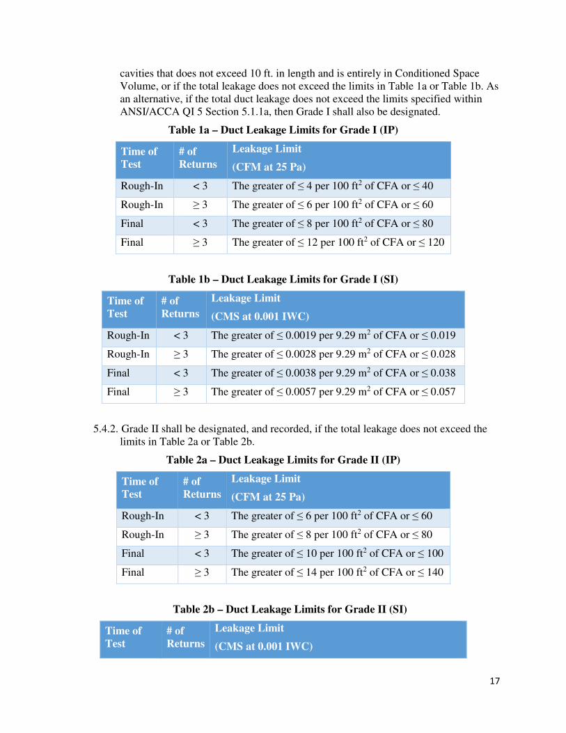
5.4.2. Grade II shall be designated, and recorded, if the total leakage does not exceed the
limits in Table 2a or Table 2b.
Table 2a – Duct Leakage Limits for Grade II (IP)
Time of
Test
# of
Returns
Leakage Limit
(CFM at 25 Pa)
Rough-In < 3 The greater of ≤ 6 per 100 ft2 of CFA or ≤ 60
Rough-In ≥ 3 The greater of ≤ 8 per 100 ft2 of CFA or ≤ 80
Final < 3 The greater of ≤ 10 per 100 ft2 of CFA or ≤ 100
Final ≥ 3 The greater of ≤ 14 per 100 ft2 of CFA or ≤ 140
Table 2b – Duct Leakage Limits for Grade II (SI)
Time of
Test
# of
Returns
Leakage Limit
(CMS at 0.001 IWC)
18
Rough-In < 3 The greater of ≤ 0.0028 per 9.29 m2 of CFA or ≤ 0.028
Rough-In ≥ 3 The greater of ≤ 0.0038 per 9.29 m2 of CFA or ≤ 0.038
Final < 3 The greater of ≤ 0.0047 per 9.29 m2 of CFA or ≤ 0.047
Final ≥ 3 The greater of ≤ 0.0066 per 9.29 m2 of CFA or ≤ 0.066
5.4.3. Unless the exception in Section 5.3 has been met, Grade III shall be designated and
recorded if the total duct leakage has not been measured or has been measured and
exceeds the limits in Section 5.4.2.
6. Task 3: Evaluation of the Blower Fan Volumetric Airflow.
6.1. Overview. This procedure shall be completed by first meeting the prerequisites in
Section 6.2, then preparing the Dwelling and Forced-Air HVAC System for testing, per
Section 6.3, then measuring the Blower Fan volumetric airflow using Section 6.4, 6.5, 6.6,
or 6.7, consistent with the guidance in Sections 6.2.1.1 through 6.2.1.4, and finally
designating the Blower Fan Volumetric Airflow grade per Section 6.8.
As an alternative to completing the procedures defined in Sections 6.4 through 6.7, if the
installed equipment contains an on-board diagnostic system that is capable of reporting the
Blower Fan volumetric airflow and that is approved for use by an entity adopting and
requiring the use of this Standard, then the reported value shall be permitted to be used.
As an alternative to completing the procedures defined in Sections 6.3 through 6.7, if an
Independent Verification Report is obtained containing the measured Blower Fan
volumetric airflow of the Forced-Air HVAC System under test, and the report is approved
for use by an entity adopting and requiring the use of this Standard, then the reported value
shall be permitted to be used.
If an on-board diagnostic system is used or Independent Verification Report is obtained,
the reported value shall be used to designate the Blower Fan Volumetric Airflow grade per
Section 6.8.
As an alternative to completing the procedures defined in Sections 6.4 through 6.7, the
following are approved for use:
6.1.1. Section 8.6 from ASTM E1554-13,
6.1.2. Normative Appendix A from ANSI/ASHRAE Standard 152-2004,
6.1.3. Section RA3.3 from the 2016 Reference Appendices for the 2016 Building Energy
Efficiency Standards of the California Energy Commission.
6.2. Prerequisites. Prior to evaluating the Blower Fan volumetric airflow, all the following
requirements shall have been met.
6.2.1. The total duct leakage shall have been evaluated in accordance with Section 5,
including all prerequisites in Section 5.2. The test procedure used to evaluate the
airflow shall be selected according to Sections 6.2.1.1 through 6.2.1.4.
6.2.1.1. If the Forced-Air HVAC System has a total amount of supply ductwork or
distribution building cavities that does not exceed 10 ft. in length and is entirely in
19
Conditioned Space Volume, then measurement of the airflow shall not be required
and the volumetric airflow grade shall be designated in accordance with Section 6.8.
6.2.1.2. If the Forced-Air HVAC System does not meet the conditions in Section 6.2.1.1
and the total duct leakage has been designated Grade I, the airflow is permitted to be
measured using the Pressure Matching Method (Section 6.4), a Flow Grid (Section
6.5), a Flow Hood (Section 6.6), or the OEM Static Pressure Table Method (Section
6.7) 26.
6.2.1.3. If the total duct leakage has been designated Grade II, the airflow is permitted
to be measured using the Pressure Matching Method with Method 1 Installation
(Section 6.4), a Flow Grid (Section 6.5), or the OEM Static Pressure Table Method
(Section 6.7).
6.2.1.4. If the total duct leakage has been designated Grade III, then Blower Fan
volumetric airflow shall not be evaluated.
6.2.2. Verification of HVAC Components. If the following components are included in
the design of the Forced-Air HVAC System under test, they shall be verified to be
present. If these components have not yet been installed, then the test shall not be
conducted. The additional requirements defined in Section 6.2.2.1 shall also be met.
6.2.2.1. HVAC equipment. The specified manufacturer(s) and model number(s) of the
equipment in the Forced-Air HVAC System under test matches the installed
equipment or supplemental documentation has been collected as defined in Section
4.2.5 and verified in accordance with Section 4.3. If the installed equipment does not
match the specified equipment in the original or supplemental documentation, then
Blower Fan volumetric airflow shall not be evaluated.
6.2.2.2. Dwelling-Unit Mechanical Ventilation Systems integrated with the HVAC
System.
6.2.2.3. Distribution systems, including supply registers and return grilles.
6.2.2.4. An air filter with the same performance rating and metric 27 as reported in
Section 4.2.5.4. 28
6.3. Procedure to Prepare the Dwelling and Forced-Air HVAC System
6.3.1. Position of Dampers. Dampers within the duct system of the Forced-Air HVAC
System under test shall be treated as follows:
6.3.1.1. Non-motorized dampers 29 that connect the Conditioned Space Volume 30 to the
exterior or to Unconditioned Space Volume shall be left in their as-found positions.
26 (Informative Note) Grade I total duct leakage is required to ensure that leakage in the return-side of the system
is sufficiently small that it does not significantly impact the measured volumetric airflow of the Blower Fan. 27 (Informative Note) Examples of performance ratings include MERV and FPR. 28 (Informative Note) Use of a new clean filter is recommended to ensure maximum airflow. 29 (Informative Note) For example, pressure-activated operable dampers, fixed dampers. 30 (Informative Note) This includes space conditioning duct systems.
20
6.3.1.2. Motorized dampers that connect the Conditioned Space Volume 30 to the
exterior or to Unconditioned Space Volume shall be placed in their closed positions
and shall not be further sealed.
6.3.1.3. Balancing dampers shall be left in their as-found position.
6.3.2. Position of Registers. Supply registers shall be left in their as-found position.
6.3.3. Ventilation Openings. Non-dampered Ventilation openings within the duct system
of intermittently or continuously operating Dwelling-Unit Mechanical Ventilation
Systems, including Ventilation systems that use the Blower Fan of the Forced-Air
HVAC System, shall not be sealed.
6.3.4. Settings for Fans Other than the HVAC System Blower Fan.
6.3.4.1. Any fans 31 that could change the pressure in either the Conditioned Space
Volume or, if present, an Unconditioned Space Volume containing the Forced-Air
HVAC System under test, shall be turned off.
6.3.4.2. If a Dwelling-Unit Mechanical Ventilation System contains a fan, other than the
Blower Fan of the Forced-Air HVAC System under test 32, that is interconnected
with the Forced-Air HVAC System under test, it shall be turned off.
6.3.5. Settings for HVAC System. If the Forced-Air HVAC System contains an Air
Conditioner, then the test shall be conducted in cooling mode. If the Forced-Air
HVAC System contains a Heat Pump, then the test shall either be conducted in the
mode with the higher design airflow, as reported in Section 4.2.5.5.1, or in both the
heating and cooling mode.
6.3.5.1. Cooling Mode.
6.3.5.1.1. If the outdoor temperature is < 55 °F (13 °C), then power to the
compressor shall be cut off 33 for the duration of the test.
6.3.5.1.2. The thermostat shall be set to cooling mode and the setpoint temperature
adjusted as low as possible 34.
6.3.5.1.3. If the Forced-Air HVAC System serves multiple zones, as reported in
Section 4.2.5.2, then manufacturer instructions shall be followed to ensure that all
zones in the Forced-Air HVAC System are calling for the required mode for
testing.
6.3.5.2. Heating Mode.
31 (Informative Note) For example, bathroom fans, clothes dryers, kitchen vent hood, attic fan, water heater
power-venting fans, or other Forced-Air HVAC System. 32 (Informative Note) For example, an inline fan, an ERV system, or an HRV system. 33 (Informative Note) For example, by flipping the circuit breaker for the compressor or pulling its disconnect
switch. 34 (Informative Note) If the Blower Fan speed type is not single-speed, as reported in Section 4.2.5.3.5, then the
system can operate at two or more speeds each for heating mode and cooling mode. Consult manufacturer
instructions to ensure that the Blower Fan is operating at the highest design speed.
21
6.3.5.2.1. The thermostat shall be set to heating mode and the setpoint temperature
adjusted as high as possible 34.
6.3.5.2.2. If the Forced-Air HVAC System serves multiple zones, as reported in
Section 4.2.5.2, then manufacturer instructions shall be followed to ensure that all
zones in the Forced-Air HVAC System are calling for the required mode for
testing.
6.4. Pressure Matching Method
6.4.1. Equipment Needed. The equipment listed in this section shall have its calibrations
checked at the manufacturer's recommended interval, and at least annually if no time
is specified.
6.4.1.1. Manometer. A device that measures pressure difference with an accuracy of ±
1% of the reading or ± 0.25 Pa (0.0010 IWC), whichever is greater.
6.4.1.2. Static Pressure Probe. A pressure measurement device capable of measuring the
static pressure within a duct system.
6.4.1.3. Fan Flowmeter. A tool comprised of a variable speed fan and a Manometer that
can convert fan pressure differentials into volumetric airflow. The fan shall be
capable of moving air into the Forced-Air HVAC System to achieve or approach the
pressure of its operating conditions, and measure volumetric airflow with an
accuracy equal to or better than ± 3% of the measured flow + 7 CFM (3.3 L/s or
0.0033 CMS).
6.4.1.4. Duct plugs, UL-181 listed tape, or other means of sealing duct holes as
approved by the Authority Having Jurisdiction.
6.4.2. Procedure to Conduct Pressure Matching Airflow Test
6.4.2.1. A hole shall be created or located in the supply side of the Forced-Air HVAC
System for the placement of the Static Pressure Probe. Moving in the direction of
airflow the hole shall be located after any heating and/or cooling equipment but
before the first supply duct run. The hole shall not be in flexible ductwork. If the
hole cannot be located or created in the supply side, then one of the other airflow test
procedures shall be used if airflow is to be measured.
6.4.2.2. The Static Pressure Probe shall be inserted into the hole, positioned according
to its manufacturer’s instructions, affixed in place so it will not move during the test 35, connected to the Manometer, and then the Manometer shall be turned on.
6.4.2.3. The Forced-Air HVAC System shall run for 10 minutes continuously.
6.4.2.4. The average pressure difference between the Static Pressure Probe and the
space where the Forced-Air HVAC System is located, Psop, shall be measured over
at least a 10-second period. If a negative reading is found, another measurement
location shall be created or located, or another procedure shall be selected if airflow
is to be measured. If the values are fluctuating by more than 0.05 IWC (12.4 Pa), this
turbulent condition shall be noted.
35 (Informative Note) For example, using a magnetic mount.
22
6.4.2.5. One of two methods shall be used to attach the Fan Flowmeter to the Forced-
Air HVAC System. Section 6.4.2.5.1 is permitted to be used for all Forced-Air
HVAC Systems. Section 6.4.2.5.2 is only permitted to be used for a Forced-Air
HVAC System with a duct system that has a single return grille.
6.4.2.5.1. Method 1 Installation: At the Blower Compartment. The Blower Fan shall
be turned off, the blower access panel removed, and an air barrier inserted
between the return duct system and the Blower Fan inlet 36 to ensure that no air
enters the blower compartment from the return duct system. The Fan Flowmeter
shall be attached to the blower compartment access, with the connection between
the Fan Flowmeter and blower compartment temporarily sealed. If the Fan
Flowmeter is to be connected to the blower compartment outside the Conditioned
Space Volume, then the door or access panel between the Conditioned Space
Volume and the blower compartment location shall be opened. The Blower Fan
shall then be turned back on.
6.4.2.5.2. Method 2 Installation: At the Return Grille. The Fan Flowmeter shall be
attached to the return grille. The area of the return grille not covered by the
connection to the Fan Flowmeter shall be temporarily sealed. Any filter in the
return duct shall be removed.
6.4.2.6. The Fan Flowmeter shall be turned on and its airflow adjusted until the static
pressure matches Psop, or if Psop cannot be reached, the Fan Flowmeter shall be
adjusted to maximum airflow.
6.4.2.7. The average airflow through the Fan Flowmeter, Qtest, and the average
coincident pressure difference, Ptest, shall be shall be measured over at least a 10-
second period. For a Dwelling located at an elevation >2,500 ft., Qtest shall be
corrected to equivalent airflow at sea level using the procedure specified by the Fan
Flowmeter manufacturer. Qtest is also permitted to be corrected for elevations
≤2,500 ft and to equivalent airflow at 68 °F (21.1 °C) for a more accurate
comparison to the design airflow.
6.4.2.8. The measured airflow, Qtest, and coincident plenum pressure, Ptest, shall be
used to determine the Blower Fan airflow at operating conditions, Qop, using
Equation 6 and recorded:
()* = (+,-+ × . �-)*�+,-+
/0.2
(6)
Where:
Qop = The Blower Fan airflow at operating conditions
Qtest = The Fan Flowmeter airflow measured in Section 6.4.2.7
Psop = The pressure in the supply side during operation measured in Section 6.4.2.4
Ptest = The pressure in the supply side during testing measured in Section 6.4.2.7
36 (Informative Note) For example, blocked at the filter slot
23
6.4.2.9. The Fan Flowmeter shall be turned off and removed; the air barrier removed, if
inserted; the blower access panel replaced, if removed; and the supply side hole shall
be sealed.
6.4.2.10. If the procedure to measure Blower Fan watt draw in Section 7 or to evaluate
refrigerant charge in Section 8 will not be conducted, then power to the compressor
shall be restored, if cut off for the test, and the thermostat(s) mode(s) and set point(s)
shall be returned to their original setting.
6.5. Flow Grid
6.5.1. Equipment Needed. The equipment listed in this section shall have its calibrations
checked at the manufacturer's recommended interval, and at least annually if no time
is specified.
6.5.1.1. Manometer. A device that measures pressure difference with an accuracy of ±
1% of the reading or ± 0.25 Pa (0.0010 IWC), whichever is greater.
6.5.1.2. Static Pressure Probe. A pressure measurement device capable of measuring the
static pressure within a duct system.
6.5.1.3. Flow Grid. A flow measurement device designed to temporarily replace the
filter in the Forced-Air HVAC System and capable of measuring the volumetric
airflow through it with an accuracy equal to or better than ± 7% of the measured
flow.
6.5.1.4. Duct plugs, UL-181 listed tape, or other means of sealing duct holes as
approved by the Authority Having Jurisdiction.
6.5.2. Procedure to Conduct Flow Grid Airflow Test
6.5.2.1. A hole shall be created or located in the supply side of the Forced-Air HVAC
System for the placement of the Static Pressure Probe. Moving in the direction of
airflow the hole shall be located after any heating and/or cooling equipment but
before the first supply duct run. The hole shall not be in flexible ductwork. If the
hole cannot be located or created in the supply side, then one of the other airflow test
procedures shall be used if airflow is to be measured.
6.5.2.2. The Static Pressure Probe shall be inserted into the hole, positioned according
to its manufacturer’s instructions, affixed in place so it will not move during the test
37, connected to the Manometer, and then the Manometer shall be turned on.
6.5.2.3. The Forced-Air HVAC System shall run for 10 minutes continuously.
6.5.2.4. The average pressure difference between the Static Pressure Probe and the
space where the Forced-Air HVAC System is located, Psop, shall be measured over
at least a 10-second period. If a negative reading is found, another measurement
location shall be created or located, or another procedure shall be selected if airflow
is to be measured. If the values are fluctuating by more than 0.05 IWC (12.4 Pa), this
turbulent condition shall be noted.
37 (Informative Note) For example, using a magnetic mount.
24
6.5.2.5. The filter shall be replaced with the appropriate flow plate of the Flow Grid.
The flow plate shall be in a location where all of the Blower Fan airflow will flow
through the Flow Grid. In addition, the flow plate shall be temporarily sealed in
place so that air must go through, rather than around, the plate. Flow Grid
manufacturer instructions shall be followed to ensure proper setup. If there are
multiple filters in the duct system 38, a Flow Grid shall be installed at each filter
location so that simultaneous measurements are taken, representing total system
airflow.
6.5.2.6. The average static pressure at the hole, Ptest, shall be measured over at least a
10-second period.
6.5.2.7. Using the pressure reading from the flow plate, the average airflow through the
Flow Grid, Qtest, shall be measured over at least a 10-second period. If multiple
Flow Grids are used, Qtest shall be the sum of the flows through each of the Flow
Grids. For a Dwelling located at an elevation >2,500 ft., Qtest shall be corrected to
equivalent airflow at sea level using the procedure specified by the Flow Grid
manufacturer. Qtest is also permitted to be corrected for elevations ≤2,500 ft and to
equivalent airflow at 68 °F (21.1 °C) for a more accurate comparison to the design
airflow.
6.5.2.8. The measured airflow, Qtest, and coincident plenum pressure, Ptest, shall be
used to determine the Blower Fan airflow at operating conditions, Qop, using
Equation 7 and recorded:
()* = (+,-+ × . �-)*�+,-+
/0.2
(7)
Where:
Qop = The Blower Fan airflow at operating conditions
Qtest = The Flow Grid airflow measured in Section 6.5.2.7
Psop = The pressure in the supply side during operation measured in Section 6.5.2.4
Ptest = The pressure in the supply side during testing measured in Section 6.5.2.6
6.5.2.9. The Flow Grid shall be removed and the filter replaced; and the supply side
hole shall be sealed.
6.5.2.10. If the procedure to measure Blower Fan watt draw in Section 7 or to evaluate
refrigerant charge in Section 8 will not be conducted, then power to the compressor
shall be restored, if cut off for the test, and the thermostat(s) mode(s) and set point(s)
shall be returned to their original setting.
6.6. Flow Hood
38 (Informative Note) For example, a system with multiple return grilles, with a filter at each grille.
25
6.6.1. Equipment Needed. The equipment listed in this section shall have its calibrations
checked at the manufacturer's recommended interval, and at least annually if no time
is specified.
6.6.1.1. Flow Hood. A device consisting of a flow capture element capable of creating
an airtight perimeter seal around the return grille, and an airflow meter capable of
measuring the volumetric airflow through the flow capture element with an airflow
range that that encompasses the design Blower Fan airflow, as reported in Section
4.2.5.5.1, at an accuracy equal to or better than ± 3% of the measured flow + 7 CFM
(3.3 L/s or 0.0033 CMS).
6.6.2. Procedure to Conduct Flow Hood Airflow Test
6.6.2.1. The Forced-Air HVAC System shall run for 10 minutes continuously, after
which the following procedure shall be completed for each return grille in the
Forced-Air HVAC System:
6.6.2.1.1. The flow capture element of the Flow Hood shall be placed over each
return grille of the Forced-Air HVAC System, ensuring that a tight perimeter seal
has been created and that the flow capture area is at least as large as the return
grille in all dimensions. If the flow capture area is smaller than the return grille in
any dimension, then a larger flow capture element shall be used or another
procedure shall be selected if airflow is to be measured.
6.6.2.1.2. The Flow Hood shall be turned on and the average airflow through the
airflow meter, Qtest, shall be measured over at least a 10-second period.
Manufacturer instructions to correct for the impacts of back-pressure within the
Flow Hood shall be followed 39.
6.6.2.1.3. For a Dwelling located at an elevation >2,500 ft., Qtest shall be corrected
to equivalent airflow at sea level using the procedure specified by the airflow
measurement device manufacturer. Qtest is also permitted to be corrected for
elevations ≤2,500 ft and to equivalent airflow at 68 °F (21.1 °C) for a more
accurate comparison to the design airflow.
6.6.2.2. If only one return grille is present in the Forced-Air HVAC System, Qop shall
equal Qtest. If multiple return grilles are present in the Forced-Air HVAC System,
Qop shall be the sum of Qtest for each of the return grilles. Qop shall be recorded.
6.6.2.3. If the procedure to measure Blower Fan watt draw in Section 7 or to evaluate
refrigerant charge in Section 8 will not be conducted, then power to the compressor
shall be restored, if cut off for the test, and the thermostat(s) mode(s) and set point(s)
shall be returned to their original setting.
6.7. OEM Static Pressure Table Method
39 (Informative Note) For example, measuring the airflow twice, once with a pressure relief flap closed and then
again with the flap open. Other manufacturers may indicate that back-pressure is measured and automatically
compensated for within the measurement tool.
26
6.7.1. Equipment Needed. The equipment listed in this section shall have its calibrations
checked at the manufacturer’s recommended interval, and at least annually if no time
is specified.
6.7.1.1. Manometer. A device that measures pressure difference with an accuracy of ±
1% of the reading or ± 0.25 Pa (0.0010 IWC), whichever is greater.
6.7.1.2. Static Pressure Probe. A pressure measurement device capable of measuring the
static pressure within a duct system.
6.7.1.3. Duct plugs, UL-181 listed tape, or other means of sealing duct holes as
approved by the Authority Having Jurisdiction.
6.7.2. Documentation Needed
6.7.2.1. The OEM Static Pressure Table shall be obtained and verified to match the
manufacturer, model number(s), and configuration of the installed equipment 40.
6.7.3. Procedure to Conduct OEM Static Pressure Airflow Test
6.7.3.1. If the Blower Fan motor type, as reported in Section 4.2.5.3.4, is ECM or Other
Motor Type, then the elevation of the system shall be verified to be ≤ 2,500 ft.
Otherwise, one of the other airflow test procedures shall be used if airflow is to be
measured.
6.7.3.2. The fan-speed setting of the Blower Fan shall be observed and recorded for the
mode that the test will be conducted in 41. The setting shall be verified to match one
of the settings listed on the OEM Static Pressure Table.
6.7.3.3. A hole shall be located or created in the return-side of the Forced-Air HVAC
system for the placement of the Static Pressure Probe. Moving in the direction of
airflow, the return-side hole shall be located after the filter but before the Blower
Fan. The hole shall not be in flexible ductwork. If the hole cannot be located or
created in the return side, then one of the other airflow test procedures shall be used
if airflow is to be measured.
6.7.3.4. A hole shall be located or created in the supply-side of the Forced-Air HVAC
System for the placement of the Static Pressure Probe. For Furnaces, moving in the
direction of airflow the supply-side hole shall be located after the Furnace but before
the evaporator coil, if a coil is present. For Heat Pumps, moving in the direction of
airflow the hole shall be located after the fan-coil but before the presence of any
other components not accounted for in the OEM Static Pressure Table 42. The hole
shall not be in flexible ductwork. If the hole cannot be located or created in the
40 (Informative Note) For example, furnace, fan-coil, and/or condenser manufacturer and model number(s);
direction of airflow such as upflow or downflow; operating voltage; and the presence of integral electric heating
elements, as applicable. 41 (Informative Note) For example, if the test will be conducted in cooling mode, the fan-speed setting for cooling
mode shall be recorded. The fan-speed setting (e.g., low, medium, high) may be indicated in a variety of ways, such
as a speed tap on the motor, a wire color, or a dip-switch setting. 42 (Informative Note) For example, if the OEM Static Pressure Table accounts for the impact of a supplemental
electric heater or states that the impact is negligible, then the hole would be located after this element. In
contrast, if the table does not account for the impact, then the hole would be located before this element.
27
supply side, then one of the other airflow test procedures shall be used if airflow is to
be measured.
6.7.3.5. The Static Pressure Probe shall be inserted into the supply-side hole, positioned
according to its manufacturer’s instructions, affixed in place so it will not move
during the test 43, connected to the Manometer, and then the Manometer shall be
turned on.
6.7.3.6. The Forced-Air HVAC System shall run for 10 minutes continuously.
6.7.3.7. The average pressure difference between the Static Pressure Probe in the
supply-side of the Forced-Air HVAC System and the space where the system is
located, Psop, shall be measured over at least a 10-second period 44. If a negative
reading is found, another measurement location shall be created or located, or
another procedure shall be selected if airflow is to be measured. If the values are
fluctuating by more than 0.05 IWC (12.4 Pa), this turbulent condition shall be noted.
6.7.3.8. The Static Pressure Probe shall be removed from the supply-side hole and
inserted into the return-side hole, positioned according to its manufacturer’s
instructions, and affixed in place so it will not move during the test 45.
6.7.3.9. The average pressure difference between the Static Pressure Probe in the return-
side of the Forced-Air HVAC System and the space where the system is located,
Prop, shall be measured over at least a 10-second period 46. If a positive reading is
found, another measurement location shall be created or located, or another
procedure shall be selected if airflow is to be measured. If the values are fluctuating
by more than 0.05 IWC (12.4 Pa), this turbulent condition shall be noted.
6.7.3.10. If the elevation of the system is > 2,500 ft. (762 m), then an elevation
adjustment factor, ρadj, shall be calculated using Equation 8a or 8b. For elevations
≤2,500 ft, ρadj is also permitted to be calculated using Equation 8a or 8b or shall
equal 1:
3�4 = 0.075170.07517 ∗ (1 − (0.0035666 ∗ E)/528)^5.2553 (8a)
Where:
Ρadj = The density adjustment factor for the elevation of the system
E = Elevation above sea level (ft.)
3�4 = 1.20411.2041 ∗ (1 − (0.0065 ∗ E)/293)^5.2553 (8b)
Where:
43 (Informative Note) For example, using a magnetic mount. 44 (Informative Note) Also known as supply External Static Pressure (e.g., +0.32 IWC) 45 (Informative Note) For example, using a magnetic mount. 46 (Informative Note) Also known as return External Static Pressure (e.g., -0.18 IWC)
28
Ρadj = The density adjustment factor for the elevation of the system
E = Elevation above sea level (m)
6.7.3.11. The total operational pressure of the system, Ptop, shall be calculated in IWC
or Pa using Equation 9 47:
���� = 3�4 ∗ (|����| + |����|) − �$����� (9)
Where:
Ptop = The total operational pressure of the system
Ρadj = The density adjustment factor, per Equation 8a or 8b
Psop = The supply-side operational pressure of the system
Prop = The return-side operational pressure of the system
Pfilter = The filter adjustment factor. If the OEM Static Pressure Table indicates
that its airflow values were generated using equipment with a filter in place, then
Pfilter shall equal 0.1 IWC (24.9 Pa). Alternatively, if the OEM Static Pressure
Table indicates the actual pressure drop of the filter that was used to generate its
airflow values, then Pfilter shall equal this value. If the OEM Static Pressure Table
either indicates that a filter was not in place when generating its values or is
ambiguous about the presence of a filter, then Pfilter shall equal 0.
6.7.3.12. The Blower Fan airflow at operating conditions, Qop, shall be determined by
looking up the airflow value on the OEM Static Pressure Table that is associated
with the observed fan-speed setting and measured Ptop and recorded. If Ptop does
not match any of the listed values on the Blower Table, interpolation between two
listed values shall be used to determine Qop. Extrapolation beyond listed values on
the Blower Table shall not be used.
6.7.3.13. The supply side and return side holes shall be sealed.
6.7.3.14. If the procedure to measure Blower Fan watt draw in Section 7 or to evaluate
refrigerant charge in Section 8 will not be conducted, then power to the compressor
shall be restored, if cut off for the test, and the thermostat(s) mode(s) and set point(s)
shall be returned to their original setting.
6.8. Designating the Blower Fan Volumetric Airflow Grade
6.8.1. If Grade I total duct leakage has been designated and the Forced-Air HVAC System
has a total amount of supply ductwork or distribution building cavities that does not
exceed 10 ft. in length and is entirely in Conditioned Space Volume, then Qdev shall
equal zero. Otherwise, Qdev, the deviation between the design-specified and field-
measured Blower Fan volumetric airflow shall be calculated using Equation 10.
(F,G = (()* − (F,-HIJ)(F,-HIJ
(10)
47 (Informative Note) For properly designed systems, common values of total External Static Pressure range from
0.3-0.5 for fan-coil systems and Furnace systems without cooling and from 0.5-0.8 IWC for Furnaces with coils.
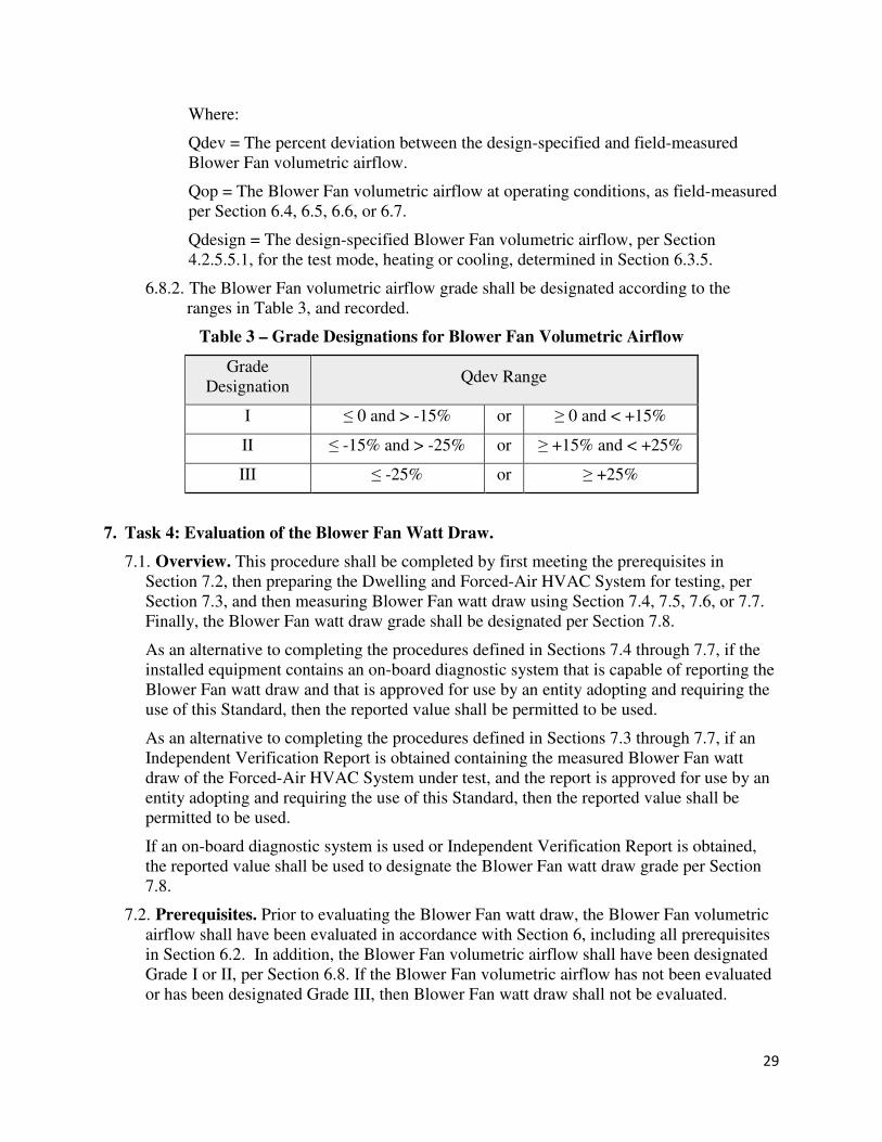
29
Where:
Qdev = The percent deviation between the design-specified and field-measured
Blower Fan volumetric airflow.
Qop = The Blower Fan volumetric airflow at operating conditions, as field-measured
per Section 6.4, 6.5, 6.6, or 6.7.
Qdesign = The design-specified Blower Fan volumetric airflow, per Section
4.2.5.5.1, for the test mode, heating or cooling, determined in Section 6.3.5.
6.8.2. The Blower Fan volumetric airflow grade shall be designated according to the
ranges in Table 3, and recorded.
Table 3 – Grade Designations for Blower Fan Volumetric Airflow
Grade
Designation Qdev Range
I ≤ 0 and > -15% or ≥ 0 and < +15%
II ≤ -15% and > -25% or ≥ +15% and < +25%
III ≤ -25% or ≥ +25%
7. Task 4: Evaluation of the Blower Fan Watt Draw.
7.1. Overview. This procedure shall be completed by first meeting the prerequisites in
Section 7.2, then preparing the Dwelling and Forced-Air HVAC System for testing, per
Section 7.3, and then measuring Blower Fan watt draw using Section 7.4, 7.5, 7.6, or 7.7.
Finally, the Blower Fan watt draw grade shall be designated per Section 7.8.
As an alternative to completing the procedures defined in Sections 7.4 through 7.7, if the
installed equipment contains an on-board diagnostic system that is capable of reporting the
Blower Fan watt draw and that is approved for use by an entity adopting and requiring the
use of this Standard, then the reported value shall be permitted to be used.
As an alternative to completing the procedures defined in Sections 7.3 through 7.7, if an
Independent Verification Report is obtained containing the measured Blower Fan watt
draw of the Forced-Air HVAC System under test, and the report is approved for use by an
entity adopting and requiring the use of this Standard, then the reported value shall be
permitted to be used.
If an on-board diagnostic system is used or Independent Verification Report is obtained,
the reported value shall be used to designate the Blower Fan watt draw grade per Section
7.8.
7.2. Prerequisites. Prior to evaluating the Blower Fan watt draw, the Blower Fan volumetric
airflow shall have been evaluated in accordance with Section 6, including all prerequisites
in Section 6.2. In addition, the Blower Fan volumetric airflow shall have been designated
Grade I or II, per Section 6.8. If the Blower Fan volumetric airflow has not been evaluated
or has been designated Grade III, then Blower Fan watt draw shall not be evaluated.
30
7.3. Procedure to Prepare the Dwelling and Forced-Air HVAC System 48
7.3.1. If an Independent Verification Report was used to determine the Blower Fan
volumetric airflow, then the procedure to prepare the Dwelling and Forced-Air
HVAC System for testing defined in Section 6.3 shall be completed.
7.3.2. Settings for HVAC System. If the Forced-Air HVAC System contains an Air
Conditioner, then the test shall be conducted in cooling mode. If the Forced-Air
HVAC System contains a Heat Pump, then the test shall either be conducted in the
mode with the higher design airflow, as reported in Section 4.2.5.5.1, or in both the
heating and cooling mode. If the Blower Fan watt draw in Ventilation Mode is being
verified, then Section 7.3.2.3 shall be followed. Blower Fan watt draw in Ventilation
Mode shall not be used to designate the Blower Fan watt draw grade per Section 7.8.
7.3.2.1. Cooling Mode.
7.3.2.1.1. If the outdoor temperature is < 55 °F (13 °C), then power to the
compressor shall be cut off 49 for the duration of the test.
7.3.2.1.2. The thermostat shall be set to cooling mode and the setpoint temperature
adjusted as low as possible 50.
7.3.2.1.3. If the Forced-Air HVAC System serves multiple zones, as reported in
Section 4.2.5.2, then manufacturer instructions shall be followed to ensure that all
zones in the Forced-Air HVAC System are calling for the required mode for
testing.
7.3.2.2. Heating Mode.
7.3.2.2.1. The thermostat shall be set to heating mode and the setpoint temperature
adjusted as high as possible 50.
7.3.2.2.2. If the Forced-Air HVAC System serves multiple zones, as reported in
Section 4.2.5.2, then manufacturer instructions shall be followed to ensure that all
zones in the Forced-Air HVAC System are calling for the required mode for
testing.
7.3.2.3. Ventilation Mode.
7.3.2.3.1. The thermostat shall be set to Ventilation Mode 51.
7.4. Portable Plug-In Watt Meter
48 (Informative Note) The procedure for preparing the HVAC settings differs from the one used in the Evaluation of
Blower Fan Volumetric Airflow. 49 (Informative Note) For example, by flipping the circuit breaker for the compressor or pulling its disconnect
switch. 50 (Informative Note) If the Blower Fan speed type is not single-speed, as reported in Section 4.2.5.3.6, then the
system can operate at two or more speeds each for heating mode and cooling mode. Consult manufacturer
instructions to ensure that the Blower Fan is operating at the highest design speed. 51 (Informative Note) Ventilation Mode may be indicated on the thermostat as “Fan-On”.
31
7.4.1. Equipment Needed. The equipment listed in this section shall have its calibrations
checked at the manufacturer's recommended interval, and at least annually if no time
is specified.
7.4.1.1. Portable Plug-In Watt Meter. The apparatus for measuring the Blower Fan watt
draw shall consist of a wattmeter capable of plugging into a standard electrical
receptacle and that itself contains a receptacle for plugging devices into to measure
their watt draw. The Meter shall have a true power measurement system (i.e., sensor
plus data acquisition system) having an accuracy of ± 2% of reading or ± 10 watts,
whichever is greater.
7.4.2. Procedure to Measure Blower Fan Watt Draw
7.4.2.1. The equipment containing the Blower Fan shall be plugged into the Portable
Plug-In Watt Meter and the Portable Plug-In Watt Meter turned on.
7.4.2.2. The Forced-Air HVAC System shall run for 10 minutes continuously before
completing Section 7.4.2.3 and beyond. The 10-minute period is permitted to include
the time the Forced-Air HVAC System was running while conducting the procedure
for evaluating the Blower Fan volumetric airflow in Section 6.
7.4.2.3. The average watt draw of the Blower Fan, Wfan, displayed on the Portable
Plug-In Watt Meter shall be measured over at least a 10-second period and recorded.
7.4.2.4. The Portable Plug-In Watt Meter shall be removed, and the equipment with the
Blower Fan plugged back into the receptacle.
7.4.2.5. If the procedure to evaluate refrigerant charge in Section 8 will not be
conducted, then power to the compressor shall be restored, if cut off for the test, and
the thermostat(s) mode(s) and set point(s) shall be returned to their original setting.
7.5. Clamp-On Watt Meter
7.5.1. Equipment Needed. The equipment listed in this section shall have its calibrations
checked at the manufacturer's recommended interval, and at least annually if no time
is specified.
7.5.1.1. Clamp-On Watt Meter. The apparatus shall consist of a clamp capable of being
placed around an electrical wire to measure current combined with leads capable of
simultaneously measuring voltage, allowing for the measurement of the Blower Fan
watt draw 52. The Meter shall have a true power measurement system (i.e., sensor
plus data acquisition system) having an accuracy of ± 2% of reading or ± 10 watts,
whichever is greater.
7.5.2. Procedure to Measure Blower Fan Watt Draw
7.5.2.1. This procedure shall be performed by parties with the proper training and using
appropriate safety equipment. The Clamp-On Watt Meter manufacturer’s operating
instructions and safety instructions shall be followed.
52 (Informative Note) Some multimeters may be capable of meeting these requirements (i.e., capable of
simultaneously measuring voltage and current and calculating Blower Fan watt draw).
32
7.5.2.2. The Blower Fan watt draw shall be measured at one of the following locations.
If neither location is available, then a different procedure shall be selected.
7.5.2.2.1. At the Service Disconnect. If a service disconnect to the equipment with
the Blower Fan is available, the service disconnect panel shall be opened.
7.5.2.2.2. At the Forced-Air HVAC System. This location is permitted to be used if
an access panel(s) provides access to the electrical supply wiring, and the Blower
Fan compartment remains closed. If this location is used, the access panel shall be
removed 53.
7.5.2.3. The Forced-Air HVAC System shall run for 10 minutes continuously before
completing Section 7.5.2.4 and beyond. The 10-minute period is permitted to include
the time the Forced-Air HVAC System was running while conducting the procedure
for evaluating the Blower Fan volumetric airflow in Section 6. If the Blower Fan is
not capable of operating with the access panels removed, then a different procedure
shall be selected if Blower Fan watt draw is to be measured.
7.5.2.4. The nameplate voltage for the equipment with the Blower Fan shall be
determined. If the nameplate voltage is between 110 V and 120 V, then Section
7.5.2.4.1 shall be followed. If the nameplate voltage is between 200 V and 240 V,
then Section 7.5.2.4.2 shall be followed.
7.5.2.4.1. Equipment with a nameplate voltage between 110 V and 120 V.
7.5.2.4.1.1. The clamp of the Clamp-On Watt Meter shall be placed around the
wire 54 supplying power to the equipment with the Blower Fan.
7.5.2.4.1.2. The leads capable of measuring voltage shall be connected to the
Clamp-On Watt Meter. The negative lead shall be placed in contact with the
grounding wire 55. The positive lead shall be placed in contact with the
connection 56 between the electrical power supply wire and the equipment’s
power supply wire 54.
7.5.2.4.1.3. The average watt draw of the Blower Fan, Wfan, displayed on the
Clamp-On Watt Meter shall be measured over at least a 10-second period and
recorded.
7.5.2.4.2. Equipment with a nameplate voltage between 200 V and 240 V.
7.5.2.4.2.1. The clamp of the Clamp-On Watt Meter shall be placed around the
first of two wires 57 supplying power to the equipment with the Blower Fan.
7.5.2.4.2.2. The leads capable of measuring voltage shall be connected to the
Clamp-On Watt Meter. The negative lead shall be placed in contact with the
connection between the first electrical power supply wire and the equipment’s 53 (Informative Note) The party conducting the test shall obtain required licensing, if any, prior to removing the
panel. If required licensing has not been obtained, an alternate test method shall be selected. 54 (Informative Note) Typically black in color. 55 (Informative Note) Typically green in color. 56 (Informative Note) Wire nuts are commonly used for this connection, in which case the lead can be inserted into
the wire nut. 57 (Informative Note) Typically either red or black in color.
33
power supply wire 57. The positive lead shall be placed in contact with the
connection between the second electrical power supply wire and the
equipment’s power supply wire 57.
7.5.2.4.2.3. The average watt draw of the Blower Fan, WfanA, displayed on the
Clamp-On Watt Meter shall be measured over at least a 10-second period.
7.5.2.4.2.4. The clamp of the Clamp-On Watt Meter shall be placed around the
second of two wires 57 supplying power to the equipment with the Blower Fan.
7.5.2.4.2.5. The negative lead shall again be placed in contact with the connection
between the first electrical power supply wire and the equipment’s power
supply wire 57. The positive lead shall again be placed in contact with the
connection between the second electrical power supply wire and the
equipment’s power supply wire 57.
7.5.2.4.2.6. The average watt draw of the Blower Fan, WfanB, displayed on the
Clamp-On Watt Meter shall be measured over at least a 10-second period.
7.5.2.4.2.7. Wfan shall be calculated by averaging WfanA and WfanB, and
recorded.
7.5.2.5. The Clamp-On Watt Meter shall be removed and the access panel(s) replaced or
service disconnect panel closed.
7.5.2.6. If the procedure to evaluate refrigerant charge in Section 8 will not be
conducted, then power to the compressor shall be restored, if cut off for the test, and
the thermostat(s) mode(s) and set point(s) shall be returned to their original setting.
7.6. Analog Utility Revenue Meter
7.6.1. Equipment Needed.
7.6.1.1. Analog Utility Revenue Meter. An analog utility revenue meter that shall have
a documented Kh factor and the ability to view the revolutions of the meter wheel.
7.6.1.2. Stopwatch. A stopwatch that provides measurements in units of seconds.
7.6.2. Procedure to Measure Blower Fan Watt Draw
7.6.2.1. The Forced-Air HVAC System shall run for 10 minutes continuously before
completing Section 7.6.2.2 and beyond. The 10-minute period is permitted to include
the time the Forced-Air HVAC System was running while conducting the procedure
for evaluating the Blower Fan volumetric airflow in Section 6.
7.6.2.2. Every circuit breaker shall be turned off except the one exclusively serving the
equipment with the Blower Fan.
7.6.2.3. The Kh factor on the revenue meter shall be recorded.
7.6.2.4. The number of full revolutions of the meter wheel shall be counted over a
period exceeding 90 seconds and both the number of revolutions, Nrev, and time
period, Trev, recorded.
7.6.2.5. The watt draw of the Blower Fan, Wfan, shall be calculated using Equation 11
and recorded:
34
K$� = (Lℎ × #��� × 3600)���� (11)
Where:
Wfan = The watt draw of the Blower Fan at operating conditions.
Kh = The conversion factor between revolutions and watts, for the meter under test.
Nrev = The number of full revolutions observed in Section 7.6.2.4.
Trev = The duration of the observation in Section 7.6.2.4, in seconds.
7.6.2.6. The circuit breakers shall be returned to their original position.
7.6.2.7. If the procedure to evaluate refrigerant charge in Section 8 will not be
conducted, then power to the compressor shall be restored, if cut off for the test, and
the thermostat(s) mode(s) and set point(s) shall be returned to their original setting.
7.7. Digital Utility Revenue Meter
7.7.1. Equipment Needed.
7.7.1.1. Digital Utility Revenue Meter. A digital utility revenue meter capable of direct
digital display of the Blower Fan watt draw.
7.7.2. Procedure to Measure Blower Fan Watt Draw
7.7.2.1. The Forced-Air HVAC System shall run for 10 minutes continuously before
completing Section 7.7.2.2 and beyond. The 10-minute period is permitted to include
the time the Forced-Air HVAC System was running while conducting the procedure
for evaluating the Blower Fan volumetric airflow in Section 6.
7.7.2.2. Every circuit breaker shall be turned off except the one exclusively serving the
equipment with the Blower Fan.
7.7.2.3. Wfan shall be read from the Digital Utility Revenue Meter, and recorded.
7.7.2.4. The circuit breakers shall be returned to their original position.
7.7.2.5. If the procedure to evaluate refrigerant charge in Section 8 will not be
conducted, then power to the compressor shall be restored, if cut off for the test, and
the thermostat(s) mode(s) and set point(s) shall be returned to their original setting.
7.8. Designating the Blower Fan Watt Draw Grade
7.8.1. Blower Fan Efficiency shall be calculated using Equation 12:
%��N�� O� P$$������� = K$�()*
(12)
Where:
Blower Fan Efficiency = The ratio of field-measured Blower Fan watt draw and
field-measured Blower Fan volumetric airflow.
Wfan = The Blower Fan watt draw at operating conditions, as field-measured per
Section 7.4, 7.5, 7.6, or 7.7.
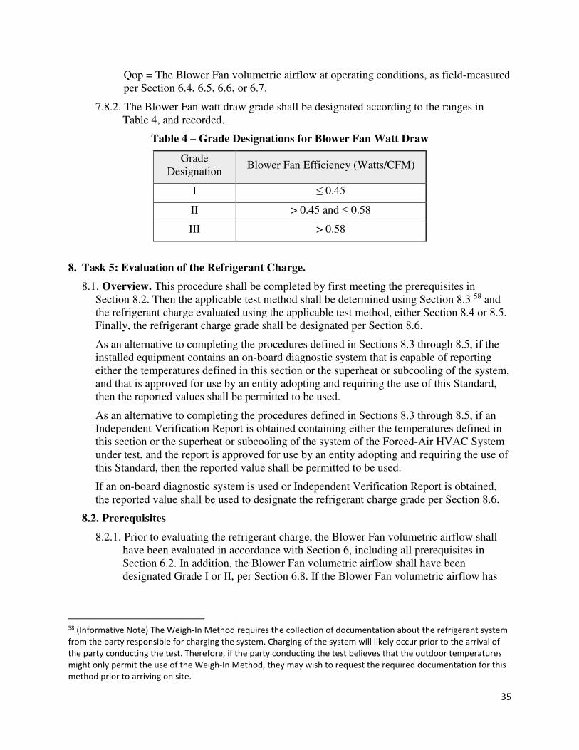
35
Qop = The Blower Fan volumetric airflow at operating conditions, as field-measured
per Section 6.4, 6.5, 6.6, or 6.7.
7.8.2. The Blower Fan watt draw grade shall be designated according to the ranges in
Table 4, and recorded.
Table 4 – Grade Designations for Blower Fan Watt Draw
Grade
Designation Blower Fan Efficiency (Watts/CFM)
I ≤ 0.45
II > 0.45 and ≤ 0.58
III > 0.58
8. Task 5: Evaluation of the Refrigerant Charge.
8.1. Overview. This procedure shall be completed by first meeting the prerequisites in
Section 8.2. Then the applicable test method shall be determined using Section 8.3 58 and
the refrigerant charge evaluated using the applicable test method, either Section 8.4 or 8.5.
Finally, the refrigerant charge grade shall be designated per Section 8.6.
As an alternative to completing the procedures defined in Sections 8.3 through 8.5, if the
installed equipment contains an on-board diagnostic system that is capable of reporting
either the temperatures defined in this section or the superheat or subcooling of the system,
and that is approved for use by an entity adopting and requiring the use of this Standard,
then the reported values shall be permitted to be used.
As an alternative to completing the procedures defined in Sections 8.3 through 8.5, if an
Independent Verification Report is obtained containing either the temperatures defined in
this section or the superheat or subcooling of the system of the Forced-Air HVAC System
under test, and the report is approved for use by an entity adopting and requiring the use of
this Standard, then the reported value shall be permitted to be used.
If an on-board diagnostic system is used or Independent Verification Report is obtained,
the reported value shall be used to designate the refrigerant charge grade per Section 8.6.
8.2. Prerequisites
8.2.1. Prior to evaluating the refrigerant charge, the Blower Fan volumetric airflow shall
have been evaluated in accordance with Section 6, including all prerequisites in
Section 6.2. In addition, the Blower Fan volumetric airflow shall have been
designated Grade I or II, per Section 6.8. If the Blower Fan volumetric airflow has
58 (Informative Note) The Weigh-In Method requires the collection of documentation about the refrigerant system
from the party responsible for charging the system. Charging of the system will likely occur prior to the arrival of
the party conducting the test. Therefore, if the party conducting the test believes that the outdoor temperatures
might only permit the use of the Weigh-In Method, they may wish to request the required documentation for this
method prior to arriving on site.
36
not been evaluated or has been designated Grade III, then refrigerant charge shall not
be evaluated.
8.3. Determination of Applicable Test Method
8.3.1. Equipment Needed. The equipment listed in this section shall have its calibrations
checked at the manufacturer's recommended interval, and at least annually if no time
is specified.
8.3.1.1. Digital Thermometer. A device that can measure dry-bulb air temperature with
an accuracy of ± 1.8 °F (1.0 °C).
8.3.2. Procedure to Determine Applicable Test Method.
8.3.2.1. The Weigh-In Method, per Section 8.5, is permitted to be used when the
following conditions are met:
8.3.2.1.1. Outdoor air temperatures do not meet the requirements of the Non-
Invasive method in Section 8.3.2.2; or,
8.3.2.1.2. The Forced-Air HVAC System is a Mini-Split Air Conditioner, Mini-Split
Heat Pump, Multi-Split Air Conditioner, or a Multi-Split Heat Pump.
8.3.2.2. The Non-Invasive Procedure, per Section 8.4, is permitted to be used when the
procedures in Section 8.3.2.2.1 and 8.3.2.2.2 are completed and the conditions in
Section 8.3.2.2.3 are met:
8.3.2.2.1. The Digital Thermometer shall be shielded from direct sun and the average
outdoor air dry-bulb-temperature shall be measured over at least a 10-second
period where the outdoor air enters the condensing unit.
8.3.2.2.2. The rated system efficiency, per Section 4.2.5.3.10, of the Forced-Air
HVAC System under test shall be determined.
8.3.2.2.3. The outdoor air dry-bulb temperature shall meet the following conditions:
8.3.2.2.3.1. Outdoor air dry-bulb temperature is between 75 °F (24 °C) and 115 °F
(46 °C) for equipment with a rated efficiency ≥ 17 SEER, or
8.3.2.2.3.2. Outdoor air dry-bulb temperature is between 70 °F (20 °C) and 115 °F
(46 °C) for all other equipment.
8.4. Non-Invasive Method
8.4.1. Procedure to Prepare the Dwelling and Forced-Air HVAC System 59
8.4.1.1. If an Independent Verification Report was used to determine the Blower Fan
volumetric airflow, then the procedure to prepare the Dwelling and Forced-Air
HVAC System for testing defined in Section 6.3 shall be completed.
8.4.1.2. Settings for HVAC System.
59 (Informative Note) The procedure for preparing the HVAC settings, damper position, and ventilation openings
differs from the one used in the Evaluation of Blower Fan Volumetric Airflow.
37
8.4.1.2.1. The thermostat shall be set to cooling mode and the setpoint temperature
adjusted as low as possible 60.
8.4.1.2.2. If the Forced-Air HVAC System serves multiple zones, as reported in
Section 4.2.5.2, then manufacturer instructions shall be followed to ensure that all
zones in the Forced-Air HVAC System are calling for the required mode for
testing.
8.4.1.3. Position of Dampers . Dampers within the duct system of the Forced-Air
HVAC System under test shall be treated as follows:
8.4.1.3.1. Non-motorized dampers 61 that connect the Conditioned Space Volume 62
to the exterior or to Unconditioned Space Volume shall be placed in their closed
position during the test and shall not be further sealed. If running the Forced-Air
HVAC System causes the non-motorized dampers to open after being placed in
their closed position, then the Ventilation openings shall be temporarily sealed. If
the Ventilation openings are not accessible, or cannot be temporarily sealed, then
refrigerant charge shall not be evaluated.
8.4.1.3.2. Motorized dampers that connect the Conditioned Space Volume 62 to the
exterior or to Unconditioned Space Volume shall be placed in their closed
positions and shall not be further sealed.
8.4.1.3.3. All balancing dampers shall be left in their as-found position.
8.4.1.4. Ventilation Openings. Non-dampered Ventilation openings within the duct
system of intermittently or continuously operating Dwelling-Unit Mechanical
Ventilation Systems, including Ventilation systems that use the Blower Fan of the
Forced-Air HVAC System, shall be temporarily sealed. If the non-dampered
Ventilation openings are not accessible, or cannot be temporarily sealed, then
refrigerant charge shall not be evaluated.
8.4.2. Equipment Needed. The equipment listed in this section shall have its calibrations
checked at the manufacturer's recommended interval, and at least annually if no time
is specified.
8.4.2.1. Digital Thermometer. A device that can measure dry-bulb air temperature with
an accuracy of ± 1.8 °F (1.0 °C).
8.4.2.2. Digital Hygrometer. A device that can measure wet-bulb air temperature with
an accuracy of ± 2.0 °F (1.1 °C) or calculate wet-bulb air temperature using
measurements of Relative Humidity (RH) with an accuracy of ± (1.8% RH +3.0% of
the measured value) at 77 °F (25 °C) and dry-bulb air temperature with an accuracy
of ± 2.0 °F (1.1 °C).
60 (Informative Note) If the Blower Fan speed type is not single-speed, as reported in Section 4.2.5.3.5, then the
system can operate at two or more speeds each for heating mode and cooling mode. Consult manufacturer
instructions to ensure that the Blower Fan is operating at the highest design speed. 61 (Informative Note) For example, pressure-activated operable dampers, fixed dampers. 62 (Informative Note) This includes space conditioning duct systems.
38
8.4.2.3. Digital Pipe Temperature Probe. A device that can attach to 63 and measure
temperatures of pipes and refrigerant lines between -4 °F (-20 °C) and 185 °F (85
°C) with an accuracy of ± 2.3 °F (1.3 °C).
8.4.3. Procedure to Evaluate the Refrigerant Charge.
8.4.3.1. Before proceeding past Section 8.4.3.5, the Forced-Air HVAC System shall run
for 15 minutes continuously 64.
8.4.3.2. The location for measuring the return air temperature shall be determined as
follows:
8.4.3.2.1. If a hole located in the return side of the Forced-Air HVAC System and is
out of line of sight of the evaporator coil 65, then the hole shall qualify for use in
this procedure.
8.4.3.2.2. If a hole does not qualify per Section 8.4.3.2.1, then the location shall be
where the indoor air stream enters the return grille closest to the Forced-Air
HVAC System.
8.4.3.3. Using the Digital Thermometer, the average return air dry bulb temperature (T
return air, db), and average return air wet-bulb temperature shall be measured over at
least a 10-second period at the location determined in Section 8.4.3.2 and recorded.
If the temperatures were measured using a hole, then the hole shall be sealed to
prevent leakage after measurements have been completed.
8.4.3.4. The return air temperatures measured in Section 8.4.3.3 shall be evaluated for
compliance with the following conditions. The following two conditions shall be
met, or the refrigerant charge shall not be evaluated using the non-invasive method 66:
8.4.3.4.1. Return air dry bulb temperature is between 70 °F (21 °C) and 80 °F (27
°C), and,
8.4.3.4.2. Return air wet-bulb temperature is ≥ 50 °F (10 °C).
8.4.3.5. The following average temperatures shall be measured over at least a 10-second
period each and recorded. All three temperatures shall be measured within a five-
minute period that begins no more than five minutes after the measurements taken in
Section 8.4.3.3 67.
8.4.3.5.1. Using the Digital Thermometer, the outdoor air dry-bulb temperature (T
outdoor air) shall be measured where the outdoor air stream enters the condensing
63 (Informative Note) For example, using a clamp, strap, or equivalent device. 64 (Informative Note) The 15-minute period is permitted to include the time the Forced-Air HVAC System was
running while conducting the procedure for evaluating the Blower Fan volumetric airflow in Section 6 and the
procedure for evaluating the Blower Fan watt draw in Section 7, as long as power to the compressor was not cut
off. 65 (Informative Note) Return air temperature is measured out of line of sight of the evaporator coil to prevent
radiant heat transfer from the coil from impacting the measured temperature. 66 (Informative Note) If these conditions could be achieved by allowing the system to run longer, that is permitted. 67 (Informative Note) This time period means that the final measurement taken in Section 8.4.3.5 must be no more
than ten minutes after the measurements taken in Section 8.4.3.3.
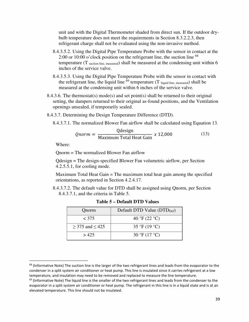
39
unit and with the Digital Thermometer shaded from direct sun. If the outdoor dry-
bulb temperature does not meet the requirements in Section 8.3.2.2.3, then
refrigerant charge shall not be evaluated using the non-invasive method.
8.4.3.5.2. Using the Digital Pipe Temperature Probe with the sensor in contact at the
2:00 or 10:00 o’clock position on the refrigerant line, the suction line 68
temperature (T suction line, measured) shall be measured at the condensing unit within 6
inches of the service valve.
8.4.3.5.3. Using the Digital Pipe Temperature Probe with the sensor in contact with
the refrigerant line, the liquid line 69 temperature (T liquid line, measured) shall be
measured at the condensing unit within 6 inches of the service valve.
8.4.3.6. The thermostat(s) mode(s) and set point(s) shall be returned to their original
setting, the dampers returned to their original as-found positions, and the Ventilation
openings unsealed, if temporarily sealed.
8.4.3.7. Determining the Design Temperature Difference (DTD).
8.4.3.7.1. The normalized Blower Fan airflow shall be calculated using Equation 13.
(���� = QdesignMaximum Total Heat Gain c 12,000 (13)
Where:
Qnorm = The normalized Blower Fan airflow
Qdesign = The design-specified Blower Fan volumetric airflow, per Section
4.2.5.5.1, for cooling mode.
Maximum Total Heat Gain = The maximum total heat gain among the specified
orientations, as reported in Section 4.2.4.17.
8.4.3.7.2. The default value for DTD shall be assigned using Qnorm, per Section
8.4.3.7.1, and the criteria in Table 5.
Table 5 – Default DTD Values
Qnorm Default DTD Value (DTDDef)
< 375 40 °F (22 °C)
≥ 375 and ≤ 425 35 °F (19 °C)
> 425 30 °F (17 °C)
68 (Informative Note) The suction line is the larger of the two refrigerant lines and leads from the evaporator to the
condenser in a split system air conditioner or heat pump. This line is insulated since it carries refrigerant at a low
temperature, and insulation may need to be removed and replaced to measure the line temperature. 69 (Informative Note) The liquid line is the smaller of the two refrigerant lines and leads from the condenser to the
evaporator in a split system air conditioner or heat pump. The refrigerant in this line is in a liquid state and is at an
elevated temperature. This line should not be insulated.
40
8.4.3.7.3. If the party responsible for conducting the start-up of the Forced-Air
HVAC System under test has provided the return air dry bulb temperature and the
suction line Saturation Temperature at the time of start-up, then the site-specific
DTD shall be calculated using Equation 14.
e�efH+, = �g,+hgJ iHg,Fj,HJ-+ikk − �-hl+H)J,-i+hgi+H)J,HJ-+ikk (14)
Where:
DTDSite = The site-specific DTD of the installed equipment.
Treturnair,db,install = The return air temperature measured by the contractor at the
time of installation
Tsuction,saturation,install = The suction line Saturation Temperature measured by
the contractor at the time of installation
8.4.3.7.4. If DTDSite, per Section 8.4.3.7.3, is within ± 3 °F (2 °C) of DTDDef, per
Section 8.4.3.7.2, then DTD shall equal DTDSite. If not, or if DTDSite has not been
calculated, then DTD shall equal DTDDef.
8.4.3.8. If the metering device type is piston or capillary tube, per Section 4.2.5.3.9,
then this Section shall be completed.
8.4.3.8.1. The Target Superheat shall be determined from the manufacturer-supplied
superheat chart for the equipment under test, or Table B1 in Appendix B 70, using
the return air wet bulb temperature measured in Section 8.4.3.3 and the outdoor
air dry bulb temperature measured in Section 8.4.3.5.1.
8.4.3.8.2. The minimum liquid line temperature shall be calculated using Equation
15.
�kHmhHF kHJ,,nHJ = �)h+F))g iHg + �kHmhHF kHJ,,nHJ,l)J-+iJ+ (15)
Where:
Tliquidline,min = The minimum allowable liquid line temperature
Toutdoor air = The outdoor air temperature, measured in Section 8.4.3.5.1
Tliquidline,min,constant = 3 °F (2 °C)
8.4.3.8.3. The maximum liquid line temperature shall be calculated using Equation
16.
�kHmhHF kHJ,,opq = �)h+F))g iHg + �kHmhHF kHJ,,opq,rstuvptv (16)
Where:
Tliquidline,max = The maximum allowable liquid line temperature
Toutdoor air = The outdoor air temperature, measured in Section 8.4.3.5.1
70 (Informative Note) If a dash mark is read from the table in Table B1, the Target Superheat is less than 5 °F and
the test cannot be performed under these conditions. Typically this indicates that the outdoor conditions are too
hot and the indoor conditions are too cold, and can be resolved by increasing the indoor temperature or testing at
another time.
41
Tliquidline,max,constant = 12 °F (7 °C)
8.4.3.8.4. If the measured liquid line temperature, per Section 8.4.3.5.3, is < T liquid
line, min or > T liquid line, max, then refrigerant charge shall not be evaluated.
8.4.3.8.5. The Target Suction Line Temperature shall be calculated using Equation
17.
�-hl+H)J kHJ,,+igI,+ = �g,+hgJ iHg,Fj − e�e + ���� �����ℎ�� (17)
Where:
Tsuctionline,target = The Target Suction Line Temperature
Treturnair,db = The return air dry bulb temperature, measured in Section 8.4.3.3
DTD = The Design Temperature Difference of the installed equipment, per Section
8.4.3.7.4
Target Superheat = The Target Superheat determined in Section 8.4.3.8.1
8.4.3.8.6. The difference between the measured suction line temperature and the
Target Suction Line Temperature shall be calculated using Equation 18 and
recorded.
e�$$������wxw = �-hl+H)J kHJ,,+igI,+ − �-hl+H)J kHJ,,n,i-hg,F (18)
Where:
DifferenceDTD = The difference between the measured suction line temperature
and the Target Suction Line Temperature.
Tsuctionline,target = The Target Suction Line Temperature, determined using
Equation 17
Tsuctionline,measured = The suction line temperature measured in Section
8.4.3.5.2
8.4.3.9. If the metering device type is TXV or EEV, per Section 4.2.5.3.9, then this
Section shall be completed.
8.4.3.9.1. The Target Subcooling shall equal the value specified in Section
4.2.5.3.9.2.
8.4.3.9.2. Determining the Condensing Temperature Over Ambient (CTOA).
8.4.3.9.2.1. The default value for CTOA shall be assigned using the SEER
reported in Section 4.2.5.3.10 and the criteria in Table 6.
Table 6 – Default CTOA Values
Reported SEER Default CTOA Value (CTOADef)
≤ 9 30 °F (16.7 °C)
> 9 and ≤ 12 25 °F (13.9 °C)
> 12 and ≤ 16 20 °F (11.1 °C)
42
> 16 15 °F (8.3 °C)
8.4.3.9.2.2. If the party responsible for conducting the start-up of the Forced-Air
HVAC System under test has provided the outdoor air dry bulb temperature
and the liquid line Condensing Temperature at the time of start-up, then the
site-specific CTOA shall be calculated using Equation 19.
��"�fH+, = � l)JF,J-HJI,HJ-+ikk − �)h+F))g iHg,HJ-+ikk (19)
Where:
CTOASite = The Condensing Temperature Over Ambient of the installed equipment
Tcondensing,install = The liquid line Condensing Temperature measured by the
contractor at the time of installation
Toutdoorair,install = The outdoor air temperature measured by the contractor at the
time of installation
8.4.3.9.2.3. If CTOASite, per Section 8.4.3.9.2.2, is within ± 3 °F (2 °C) of
CTOADef, per Section 8.4.3.9.2.1, then CTOA shall equal CTOASite. If not, or
if CTOASite has not been calculated, then CTOA shall equal CTOADef.
8.4.3.9.3. The minimum suction line temperature shall be calculated using Equation
20.
�-hl+H)J kHJ,,nHJ = �g,+hgJ iHg,Fj − e�e + �-hl+H)J kHJ,,nHJ,l)J-+iJ+ (20)
Where:
Tsuctionline,min = The minimum allowable suction line temperature
Treturnair,db = The return air dry bulb temperature, measured in Section 8.4.3.3
DTD = The Design Temperature Difference of the installed equipment, per Section
8.4.3.7.4
Tsuctionline,min,constant = 3 °F (2 °C).
8.4.3.9.4. The maximum suction line temperature shall be calculated using Equation
21.
�-hl+H)J kHJ,,opq = �g,+hgJ iHg,Fj − e�e + �-hl+H)J kHJ,,opq,rstuvptv (21)
Where:
Tsuctionline,max = The maximum allowable suction line temperature
Treturnair,db = The return air dry bulb temperature, measured in Section 8.4.3.3
DTD = The Design Temperature Difference of the installed equipment, per Section
8.4.3.7.4
Tsuctionline,max,constant = 26 °F (14 °C).
43
8.4.3.9.5. If the measured suction line temperature, per Section 8.4.3.5.2, is > 65 °F
(18 °C), < T suction line, min, or > T suction line, max, then refrigerant charge shall not be
evaluated.
8.4.3.9.6. The Target Liquid Line temperature shall be calculated using Equation 22.
�kHmhHF kHJ,,+igI,+ = �)h+F))g iHg + ��"� − ���� �� ������ (22)
Where
Tliquidline,target = The Target Liquid Line temperature
Toutdoorair = The outdoor air temperature, measured in Section 8.4.3.5.1
CTOA = The Condensing Temperature Over Ambient of the installed equipment,
per Section 8.4.3.9.2.3
Target Subcooling = The Target Subcooling determined in Section 8.4.3.9.1
8.4.3.9.7. The difference between the measured liquid line temperature and the
Target Liquid Line temperature shall be calculated using Equation 23 and
recorded.
e�$$������yxz{ = � kHmhHF kHJ,,+igI,+ − �kHmhHF kHJ,,n,i-hg,F (23)
DifferenceCTOA = The difference between the measured liquid line temperature
and the Target Liquid Line temperature.
Tliquidline,target = The Target Liquid Line temperature, determined using
Equation 22
Tliquidline,measured = The liquid line temperature measured in Section 8.4.3.5.3
8.5. Weigh-In Method
8.5.1. Equipment Needed.
8.5.1.1. Measuring Tape. A device that can determine length with an accuracy of ± 1/16
inch (1.6 mm).
8.5.2. Documentation Needed
8.5.2.1. The following documentation about the refrigerant system of the Forced-Air
HVAC System under test shall be collected from the party responsible for charging
the system.
8.5.2.1.1. The total weight of refrigerant added to or removed from the system, an
indication of whether the refrigerant was added or was removed, and an indication
of whether the factory-supplied refrigerant was first removed 71.
8.5.2.1.2. One or more photographs showing the scale displaying the total weight of
refrigerant added or removed from the system indicated per Section 8.5.2.1.1. The
71 (Informative Note) An indication of whether refrigerant was added or removed may be indicated by the phrase
“10 Oz. Added” or “10 Oz. Removed.” An indication of whether the factory-supplied refrigerant was first removed
may be indicated by the phrase “Factory-supplied charge not removed” or “Factory-supplied charge removed.”
44
photographs shall be timestamped and geotagged to indicate the location of the
Forced-Air HVAC System under test.
8.5.2.1.3. The total length of the liquid line 72.
8.5.2.1.4. The outside diameter of the liquid line.
8.5.2.1.5. The length of liquid line accounted for in the factory-supplied charge 73.
8.5.2.1.6. The weight of the factory-supplied refrigerant 74.
8.5.2.1.7. The weight of the refrigerant added to the system for specific components, 75 other than the incremental length of the liquid line.
8.5.3. Procedure to Evaluate the Refrigerant Charge
8.5.3.1. Using the Measuring Tape, the total length 76 of the liquid line shall be
measured to the nearest foot (0.3 meters) 72, and recorded. If the refrigerant line has
been pre-marked to indicate line lengths, then the markings are permitted to be used
in lieu of the Measuring Tape.
8.5.3.2. Using the Measuring Tape, the circumference of the liquid line shall be
measured to the nearest 1/16th of an inch (1.6 mm) and divided by 3.14 to calculate
the outer diameter, and recorded.
8.5.3.3. The Delta Line Length shall be calculated using Equation 24.
!F,k+i = !n,i-hg,F − !F,|ihk+ (24)
Where:
Ldelta = The difference in line length between the measured liquid line length and
the liquid line length accounted for by the factory-supplied charge.
Lmeasured = The liquid line length measured in Section 8.5.3.1.
Ldefault = The liquid line length accounted for by the factory-supplied charge, from
Section 8.5.2.1.5.
8.5.3.4. The weight of the refrigerant required for the incremental liquid line length,
Wlength_ant, shall be determined from Table C1 in Appendix C using Ldelta, from
Equation 24, and the outside diameter of the liquid line, from Section 8.5.3.2.
8.5.3.5. The total anticipated refrigerant weight shall be calculated using Equation 25.
72 (Informative Note) The liquid line is the smaller of the two refrigerant lines and leads from the condenser to the
evaporator in a split system air conditioner or heat pump. The refrigerant in this line is in a liquid state and is at an
elevated temperature. This line should not be insulated. 73 (Informative Note) Systems typically come charged from the factory to account for a default length of refrigerant
line, often 15 feet. Manufacturer instructions will direct installers to add or remove refrigerant if the actual line
length is longer or shorter than this default length. 74 (Informative Note) The factory-supplied charge is typically indicated on the condenser nameplate. 75 (Informative Note) For correct charge, additional refrigerant may be required if the system was fully evacuated,
or there are additional components installed (e.g., filter drier). 76 (Informative Note) For Multi-splits, the total length of the liquid line includes the refrigerant lines going to all
indoor sections.
45
K���_�� = K����ℎ_�� + K���������_��� + K$�����_��� (25)
Where:
Wtot_ant = The total anticipated weight of refrigerant.
Wlength_ant = The anticipated weight of the refrigerant required for the incremental
liquid line length determined in Section 8.5.3.4.
Wcomponent_rep = The reported weight of refrigerant added to the system for
specific components, other than the incremental length of the liquid line, from
Section 8.5.2.1.7.
Wfactory_rep = The reported weight of factory-supplied refrigerant from Section
8.5.2.1.6.
8.5.3.6. The total reported refrigerant weight, Wtot_rep, shall equal the value reported
in Section 8.5.2.1.1 if the factory-supplied refrigerant was first removed, or shall be
calculated using Equation 26 if not.
K���_��� = K����ℎ_��� + K���������_��� + K$�����_��� (26)
Where:
Wtot_rep = The total reported weight of refrigerant.
Wlength_rep = The reported weight of the refrigerant added or removed for the
incremental liquid line length, as reported in Section 8.5.2.1.1
Wcomponent_rep = The reported weight of refrigerant added to the system for
specific components, other than the incremental length of the liquid line from
Section 8.5.2.1.7.
Wfactory_rep = The reported weight of factory-supplied refrigerant from Section
8.5.2.1.6.
8.5.3.7. The deviation between the total anticipated and total reported refrigerant weight
shall be calculated using Equation 27.
K��� = K���_��� − K���_��K���_�� (27)
Where:
Wdev = The percent deviation between the total anticipated and total reported
refrigerant weight.
Wtot_rep = The total reported weight of refrigerant, from Section 8.5.3.6.
Wtot_ant = The total anticipated weight of refrigerant, from Section 8.5.3.5
8.6. Designating the Refrigerant Charge Grade
8.6.1. If the superheat or subcooling of the Forced-Air HVAC System under test was
reported using an on-board diagnostic system or through an Independent Verification
Report, then Grade I shall be designated if the superheat or subcooling deviation is
within the limits specified within ANSI/ACCA QI 5 Section 4.3.1.
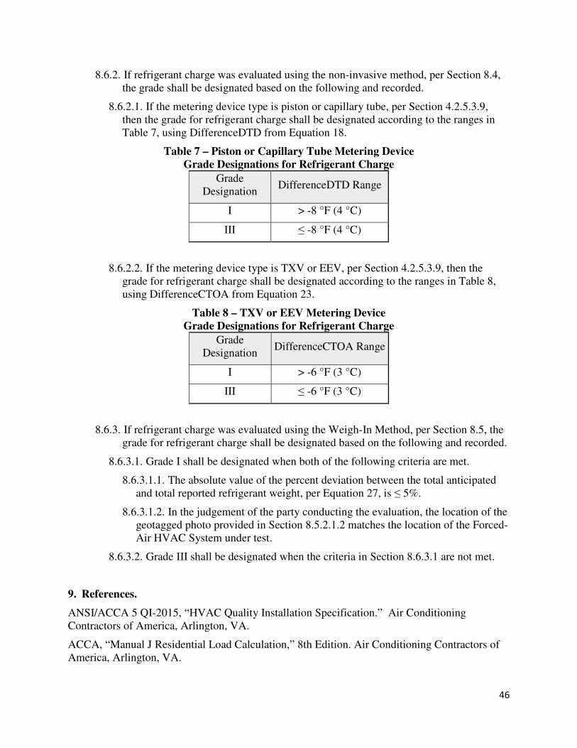
46
8.6.2. If refrigerant charge was evaluated using the non-invasive method, per Section 8.4,
the grade shall be designated based on the following and recorded.
8.6.2.1. If the metering device type is piston or capillary tube, per Section 4.2.5.3.9,
then the grade for refrigerant charge shall be designated according to the ranges in
Table 7, using DifferenceDTD from Equation 18.
Table 7 – Piston or Capillary Tube Metering Device
Grade Designations for Refrigerant Charge
Grade
Designation DifferenceDTD Range
I > -8 °F (4 °C)
III ≤ -8 °F (4 °C)
8.6.2.2. If the metering device type is TXV or EEV, per Section 4.2.5.3.9, then the
grade for refrigerant charge shall be designated according to the ranges in Table 8,
using DifferenceCTOA from Equation 23.
Table 8 – TXV or EEV Metering Device
Grade Designations for Refrigerant Charge
Grade
Designation DifferenceCTOA Range
I > -6 °F (3 °C)
III ≤ -6 °F (3 °C)
8.6.3. If refrigerant charge was evaluated using the Weigh-In Method, per Section 8.5, the
grade for refrigerant charge shall be designated based on the following and recorded.
8.6.3.1. Grade I shall be designated when both of the following criteria are met.
8.6.3.1.1. The absolute value of the percent deviation between the total anticipated
and total reported refrigerant weight, per Equation 27, is ≤ 5%.
8.6.3.1.2. In the judgement of the party conducting the evaluation, the location of the
geotagged photo provided in Section 8.5.2.1.2 matches the location of the Forced-
Air HVAC System under test.
8.6.3.2. Grade III shall be designated when the criteria in Section 8.6.3.1 are not met.
9. References.
ANSI/ACCA 5 QI-2015, “HVAC Quality Installation Specification.” Air Conditioning
Contractors of America, Arlington, VA.
ACCA, “Manual J Residential Load Calculation,” 8th Edition. Air Conditioning Contractors of
America, Arlington, VA.
47
ACCA, “Manual S Residential Heating and Cooling Equipment Selection.” Air Conditioning
Contractors of America, Arlington, VA.
ASHRAE Handbook of Fundamentals, 2013. American Society of Heating Refrigerating and Air
Conditioning Engineers, Atlanta, GA.
ASHRAE Handbook of Fundamentals, 2017. American Society of Heating Refrigerating and Air
Conditioning Engineers, Atlanta, GA.
ANSI/ASHRAE 152-2004, “Method of Test for Determining the Design and Seasonal
Efficiencies of Residential Thermal Distribution Systems.” American Society of Heating,
Refrigerating and Air Conditioning Engineers, Atlanta, GA
ANSI/ASHRAE 62.2-2010, “Ventilation and Acceptable Indoor Air Quality in Low Rise
Buildings.” American Society of Heating, Refrigerating, and Air Conditioning Engineers,
Atlanta, GA, 2013.
ANSI/ASHRAE 62.2-2013, “Ventilation and Acceptable Indoor Air Quality in Low Rise
Buildings.” American Society of Heating, Refrigerating, and Air Conditioning Engineers,
Atlanta, GA, 2013.
ANSI/ASHRAE 62.2-2016, “Ventilation and Acceptable Indoor Air Quality in Low Rise
Buildings.” American Society of Heating, Refrigerating, and Air Conditioning Engineers,
Atlanta, GA, 2016.
ANSI/RESNET/ICC 380-2019, “Standard for Testing Airtightness of Building Enclosures,
Airtightness of Heating and Cooling Air Distribution Systems, and Airflow of Mechanical
Ventilation Systems” and ANSI approved Addenda. Residential Energy Services Network,
Oceanside, CA.
ASTM E1554-13, “Standard Test Methods for Determining Air Leakage of Air Distribution
Systems by Fan Pressurization.” ASTM International, West Conshohocken, PA. 2018.
CEC-400-2015-038-CMF, “2016 Reference Appendices for the 2016 Building Energy
Efficiency Standards of the California Energy Commission.” California Energy
Commission, Sacramento, CA.
UL 181-2013, “Standard for Factory-Made Air Ducts and Air Connectors.” Underwriters’
Laboratories, Northbrook, IL.
48
Appendix A (Normative) –
Design Temperature Limits by State and County, and U.S. Territory
[Due to size, see file, “Appendix A - HVAC Design Temperature Limits v1 2018-02-07”]
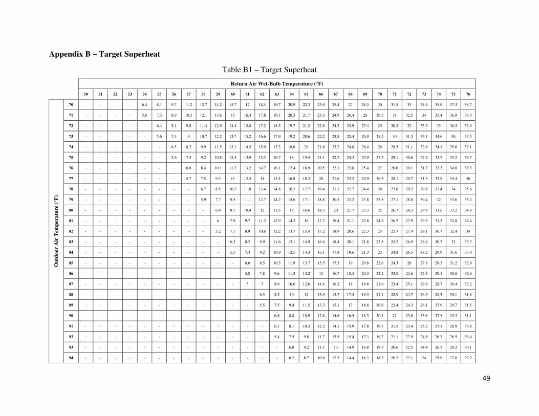
49
Appendix B – Target Superheat
Table B1 – Target Superheat
Return Air Wet-Bulb Temperature (°F)
50 51 52 53 54 55 56 57 58 59 60 61 62 63 64 65 66 67 68 69 70 71 72 73 74 75 76
Ou
tdo
or
Air
Tem
per
atu
re (
°F)
70 - - - - 6.4 8.1 9.7 11.2 12.7 14.2 15.7 17 18.4 19.7 20.9 22.3 23.9 25.4 27 28.5 30 31.5 33 34.4 35.9 37.3 38.7
71 - - - - 5.6 7.3 8.9 10.5 12.1 13.6 15 16.4 17.8 19.1 20.3 21.7 23.3 24.9 26.4 28 29.5 31 32.5 34 35.4 36.9 38.3
72 - - - - - 6.4 8.1 9.8 11.4 12.9 14.4 15.8 17.2 18.5 19.7 21.2 22.8 24.3 25.9 27.4 29 30.5 32 33.5 35 36.5 37.9
73 - - - - - 5.6 7.3 9 10.7 12.2 13.7 15.2 16.6 17.9 19.2 20.6 22.2 23.8 25.4 26.9 28.5 30 31.5 33.1 34.6 36 37.5
74 - - - - - - 6.5 8.2 9.9 11.5 13.1 14.5 15.9 17.3 18.6 20 21.6 23.2 24.8 26.4 28 29.5 31.1 32.6 34.1 35.6 37.1
75 - - - - - - 5.6 7.4 9.2 10.8 12.4 13.9 15.3 16.7 18 19.4 21.1 22.7 24.3 25.9 27.5 29.1 30.6 32.2 33.7 35.2 36.7
76 - - - - - - - 6.6 8.4 10.1 11.7 13.2 14.7 16.1 17.4 18.9 20.5 22.1 23.8 25.4 27 28.6 30.1 31.7 33.3 34.8 36.3
77 - - - - - - - 5.7 7.5 9.3 11 12.5 14 15.4 16.8 18.3 20 21.6 23.2 24.9 26.5 28.1 29.7 31.3 32.8 34.4 36
78 - - - - - - - - 6.7 8.5 10.2 11.8 13.4 14.8 16.2 17.7 19.4 21.1 22.7 24.4 26 27.6 29.2 30.8 32.4 34 35.6
79 - - - - - - - - 5.9 7.7 9.5 11.1 12.7 14.2 15.6 17.1 18.8 20.5 22.2 23.8 25.5 27.1 28.8 30.4 32 33.6 35.2
80 - - - - - - - - - 6.9 8.7 10.4 12 13.5 15 16.6 18.3 20 21.7 23.3 25 26.7 28.3 29.9 31.6 33.2 34.8
81 - - - - - - - - - 6 7.9 9.7 11.3 12.9 14.3 16 17.7 19.4 21.1 22.8 24.5 26.2 27.9 29.5 31.2 32.8 34.4
82 - - - - - - - - - 5.2 7.1 8.9 10.6 12.2 13.7 15.4 17.2 18.9 20.6 22.3 24 25.7 27.4 29.1 30.7 32.4 34
83 - - - - - - - - - - 6.3 8.2 9.9 11.6 13.1 14.9 16.6 18.4 20.1 21.8 23.5 25.2 26.9 28.6 30.3 32 33.7
84 - - - - - - - - - - 5.5 7.4 9.2 10.9 12.5 14.3 16.1 17.8 19.6 21.3 23 24.8 26.5 28.2 29.9 31.6 33.3
85 - - - - - - - - - - - 6.6 8.5 10.3 11.9 13.7 15.5 17.3 19 20.8 22.6 24.3 26 27.8 29.5 31.2 32.9
86 - - - - - - - - - - - 5.8 7.8 9.6 11.3 13.2 15 16.7 18.5 20.3 22.1 23.8 25.6 27.3 29.1 30.8 32.6
87 - - - - - - - - - - - 5 7 8.9 10.6 12.6 14.4 16.2 18 19.8 21.6 23.4 25.1 26.9 28.7 30.4 32.2
88 - - - - - - - - - - - - 6.3 8.2 10 12 13.9 15.7 17.5 19.3 21.1 22.9 24.7 26.5 28.3 30.1 31.8
89 - - - - - - - - - - - - 5.5 7.5 9.4 11.5 13.3 15.1 17 18.8 20.6 22.4 24.3 26.1 27.9 29.7 31.5
90 - - - - - - - - - - - - - 6.8 8.8 10.9 12.8 14.6 16.5 18.3 20.1 22 23.8 25.6 27.5 29.3 31.1
91 - - - - - - - - - - - - - 6.1 8.1 10.3 12.2 14.1 15.9 17.8 19.7 21.5 23.4 25.2 27.1 28.9 30.8
92 - - - - - - - - - - - - - 5.4 7.5 9.8 11.7 13.5 15.4 17.3 19.2 21.1 22.9 24.8 26.7 28.5 30.4
93 - - - - - - - - - - - - - - 6.8 9.2 11.1 13 14.9 16.8 18.7 20.6 22.5 24.4 26.3 28.2 30.1
94 - - - - - - - - - - - - - - 6.2 8.7 10.6 12.5 14.4 16.3 18.2 20.2 22.1 24 25.9 27.8 29.7
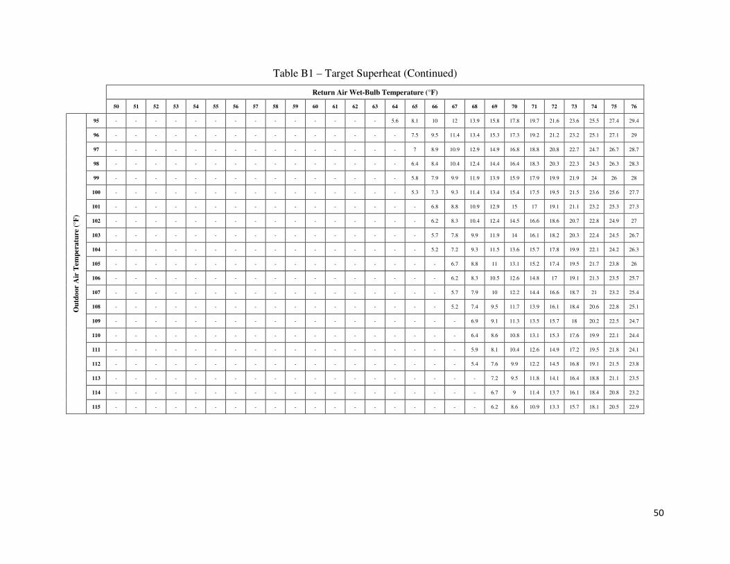
50
Table B1 – Target Superheat (Continued)
Return Air Wet-Bulb Temperature (°F)
50 51 52 53 54 55 56 57 58 59 60 61 62 63 64 65 66 67 68 69 70 71 72 73 74 75 76
Ou
tdo
or
Air
Tem
per
atu
re (
°F)
95 - - - - - - - - - - - - - - 5.6 8.1 10 12 13.9 15.8 17.8 19.7 21.6 23.6 25.5 27.4 29.4
96 - - - - - - - - - - - - - - - 7.5 9.5 11.4 13.4 15.3 17.3 19.2 21.2 23.2 25.1 27.1 29
97 - - - - - - - - - - - - - - - 7 8.9 10.9 12.9 14.9 16.8 18.8 20.8 22.7 24.7 26.7 28.7
98 - - - - - - - - - - - - - - - 6.4 8.4 10.4 12.4 14.4 16.4 18.3 20.3 22.3 24.3 26.3 28.3
99 - - - - - - - - - - - - - - - 5.8 7.9 9.9 11.9 13.9 15.9 17.9 19.9 21.9 24 26 28
100 - - - - - - - - - - - - - - - 5.3 7.3 9.3 11.4 13.4 15.4 17.5 19.5 21.5 23.6 25.6 27.7
101 - - - - - - - - - - - - - - - - 6.8 8.8 10.9 12.9 15 17 19.1 21.1 23.2 25.3 27.3
102 - - - - - - - - - - - - - - - - 6.2 8.3 10.4 12.4 14.5 16.6 18.6 20.7 22.8 24.9 27
103 - - - - - - - - - - - - - - - - 5.7 7.8 9.9 11.9 14 16.1 18.2 20.3 22.4 24.5 26.7
104 - - - - - - - - - - - - - - - - 5.2 7.2 9.3 11.5 13.6 15.7 17.8 19.9 22.1 24.2 26.3
105 - - - - - - - - - - - - - - - - - 6.7 8.8 11 13.1 15.2 17.4 19.5 21.7 23.8 26
106 - - - - - - - - - - - - - - - - - 6.2 8.3 10.5 12.6 14.8 17 19.1 21.3 23.5 25.7
107 - - - - - - - - - - - - - - - - - 5.7 7.9 10 12.2 14.4 16.6 18.7 21 23.2 25.4
108 - - - - - - - - - - - - - - - - - 5.2 7.4 9.5 11.7 13.9 16.1 18.4 20.6 22.8 25.1
109 - - - - - - - - - - - - - - - - - - 6.9 9.1 11.3 13.5 15.7 18 20.2 22.5 24.7
110 - - - - - - - - - - - - - - - - - - 6.4 8.6 10.8 13.1 15.3 17.6 19.9 22.1 24.4
111 - - - - - - - - - - - - - - - - - - 5.9 8.1 10.4 12.6 14.9 17.2 19.5 21.8 24.1
112 - - - - - - - - - - - - - - - - - - 5.4 7.6 9.9 12.2 14.5 16.8 19.1 21.5 23.8
113 - - - - - - - - - - - - - - - - - - - 7.2 9.5 11.8 14.1 16.4 18.8 21.1 23.5
114 - - - - - - - - - - - - - - - - - - - 6.7 9 11.4 13.7 16.1 18.4 20.8 23.2
115 - - - - - - - - - - - - - - - - - - - 6.2 8.6 10.9 13.3 15.7 18.1 20.5 22.9
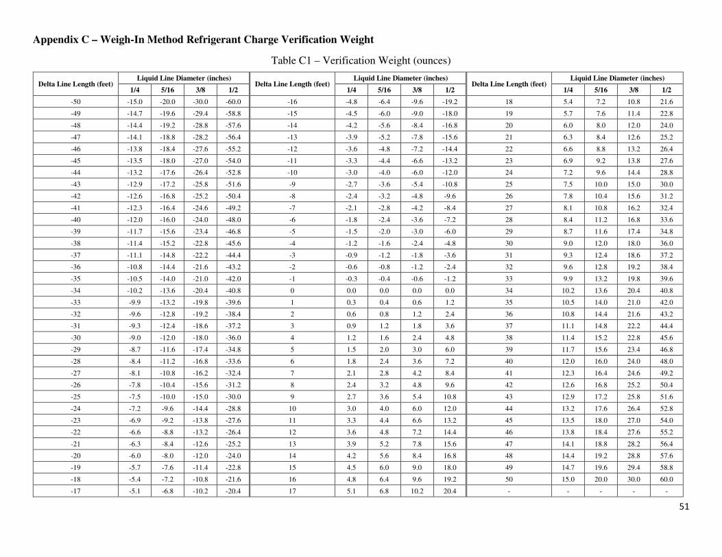
51
Appendix C – Weigh-In Method Refrigerant Charge Verification Weight
Table C1 – Verification Weight (ounces)
Delta Line Length (feet) Liquid Line Diameter (inches)
Delta Line Length (feet) Liquid Line Diameter (inches)
Delta Line Length (feet) Liquid Line Diameter (inches)
1/4 5/16 3/8 1/2 1/4 5/16 3/8 1/2 1/4 5/16 3/8 1/2
-50 -15.0 -20.0 -30.0 -60.0 -16 -4.8 -6.4 -9.6 -19.2 18 5.4 7.2 10.8 21.6
-49 -14.7 -19.6 -29.4 -58.8 -15 -4.5 -6.0 -9.0 -18.0 19 5.7 7.6 11.4 22.8
-48 -14.4 -19.2 -28.8 -57.6 -14 -4.2 -5.6 -8.4 -16.8 20 6.0 8.0 12.0 24.0
-47 -14.1 -18.8 -28.2 -56.4 -13 -3.9 -5.2 -7.8 -15.6 21 6.3 8.4 12.6 25.2
-46 -13.8 -18.4 -27.6 -55.2 -12 -3.6 -4.8 -7.2 -14.4 22 6.6 8.8 13.2 26.4
-45 -13.5 -18.0 -27.0 -54.0 -11 -3.3 -4.4 -6.6 -13.2 23 6.9 9.2 13.8 27.6
-44 -13.2 -17.6 -26.4 -52.8 -10 -3.0 -4.0 -6.0 -12.0 24 7.2 9.6 14.4 28.8
-43 -12.9 -17.2 -25.8 -51.6 -9 -2.7 -3.6 -5.4 -10.8 25 7.5 10.0 15.0 30.0
-42 -12.6 -16.8 -25.2 -50.4 -8 -2.4 -3.2 -4.8 -9.6 26 7.8 10.4 15.6 31.2
-41 -12.3 -16.4 -24.6 -49.2 -7 -2.1 -2.8 -4.2 -8.4 27 8.1 10.8 16.2 32.4
-40 -12.0 -16.0 -24.0 -48.0 -6 -1.8 -2.4 -3.6 -7.2 28 8.4 11.2 16.8 33.6
-39 -11.7 -15.6 -23.4 -46.8 -5 -1.5 -2.0 -3.0 -6.0 29 8.7 11.6 17.4 34.8
-38 -11.4 -15.2 -22.8 -45.6 -4 -1.2 -1.6 -2.4 -4.8 30 9.0 12.0 18.0 36.0
-37 -11.1 -14.8 -22.2 -44.4 -3 -0.9 -1.2 -1.8 -3.6 31 9.3 12.4 18.6 37.2
-36 -10.8 -14.4 -21.6 -43.2 -2 -0.6 -0.8 -1.2 -2.4 32 9.6 12.8 19.2 38.4
-35 -10.5 -14.0 -21.0 -42.0 -1 -0.3 -0.4 -0.6 -1.2 33 9.9 13.2 19.8 39.6
-34 -10.2 -13.6 -20.4 -40.8 0 0.0 0.0 0.0 0.0 34 10.2 13.6 20.4 40.8
-33 -9.9 -13.2 -19.8 -39.6 1 0.3 0.4 0.6 1.2 35 10.5 14.0 21.0 42.0
-32 -9.6 -12.8 -19.2 -38.4 2 0.6 0.8 1.2 2.4 36 10.8 14.4 21.6 43.2
-31 -9.3 -12.4 -18.6 -37.2 3 0.9 1.2 1.8 3.6 37 11.1 14.8 22.2 44.4
-30 -9.0 -12.0 -18.0 -36.0 4 1.2 1.6 2.4 4.8 38 11.4 15.2 22.8 45.6
-29 -8.7 -11.6 -17.4 -34.8 5 1.5 2.0 3.0 6.0 39 11.7 15.6 23.4 46.8
-28 -8.4 -11.2 -16.8 -33.6 6 1.8 2.4 3.6 7.2 40 12.0 16.0 24.0 48.0
-27 -8.1 -10.8 -16.2 -32.4 7 2.1 2.8 4.2 8.4 41 12.3 16.4 24.6 49.2
-26 -7.8 -10.4 -15.6 -31.2 8 2.4 3.2 4.8 9.6 42 12.6 16.8 25.2 50.4
-25 -7.5 -10.0 -15.0 -30.0 9 2.7 3.6 5.4 10.8 43 12.9 17.2 25.8 51.6
-24 -7.2 -9.6 -14.4 -28.8 10 3.0 4.0 6.0 12.0 44 13.2 17.6 26.4 52.8
-23 -6.9 -9.2 -13.8 -27.6 11 3.3 4.4 6.6 13.2 45 13.5 18.0 27.0 54.0
-22 -6.6 -8.8 -13.2 -26.4 12 3.6 4.8 7.2 14.4 46 13.8 18.4 27.6 55.2
-21 -6.3 -8.4 -12.6 -25.2 13 3.9 5.2 7.8 15.6 47 14.1 18.8 28.2 56.4
-20 -6.0 -8.0 -12.0 -24.0 14 4.2 5.6 8.4 16.8 48 14.4 19.2 28.8 57.6
-19 -5.7 -7.6 -11.4 -22.8 15 4.5 6.0 9.0 18.0 49 14.7 19.6 29.4 58.8
-18 -5.4 -7.2 -10.8 -21.6 16 4.8 6.4 9.6 19.2 50 15.0 20.0 30.0 60.0
-17 -5.1 -6.8 -10.2 -20.4 17 5.1 6.8 10.2 20.4 - - - - -
Related Documents