Resistivity - resistance

Resistivity - resistance
Dec 31, 2015
Resistivity - resistance. The applied voltage or current can cause heating of the material, which can change its resistivity. Even if heating of the sample is not a problem, Ohm’s law is not always obeyed. - PowerPoint PPT Presentation
Welcome message from author
This document is posted to help you gain knowledge. Please leave a comment to let me know what you think about it! Share it to your friends and learn new things together.
Transcript

Resistivity - resistance
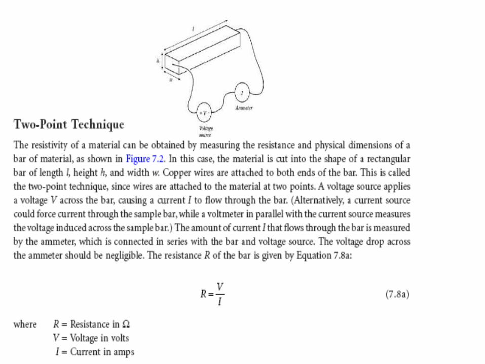
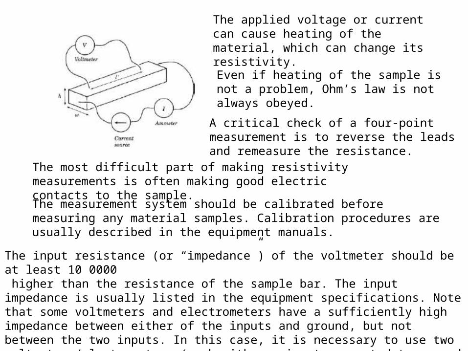
The most difficult part of making resistivity measurements is often making good electric contacts to the sample.
The measurement system should be calibrated before measuring any material samples. Calibration procedures are usually described in the equipment manuals.
The input resistance (or “impedance”) of the voltmeter should be at least 10 0000 higher than the resistance of the sample bar. The input impedance is usually listed in the equipment specifications. Note that some voltmeters and electrometers have a sufficiently high impedance between either of the inputs and ground, but not between the two inputs. In this case, it is necessary to use two voltmeters/electrometers (each with one input connected to ground and the other input connected to the sample bar)
The applied voltage or current can cause heating of the material, which can change its resistivity.
Even if heating of the sample is not a problem, Ohm’s law is not always obeyed.
A critical check of a four-point measurement is to reverse the leads and remeasure the resistance.
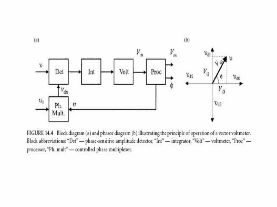
Voltage and current comparison

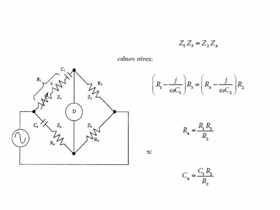
Wheatstone bridge

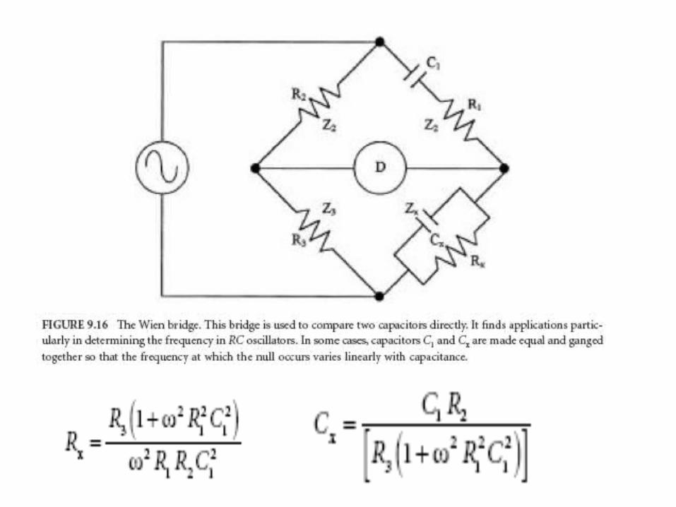
Capacitance


Inductivity


Current and voltage method


Bridge - method

Resonance - method
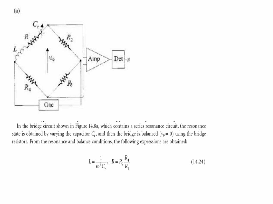

In the “shunted T” network presented in Figure 14.8b, the state of balance (i.e., the minimal voltage v0 value) is achieved by tuning the multiloop
LCR circuit to parallel resonance. The circuit analysis [7] is based on the “star-delta” transformation of the CrRrCr element loop and leads to the relations for L and R values:
Up to 100Mhz
Related Documents