24-10-2017 1 Resistance Welding (RW) A group of fusion welding processes that use a combination of heat and pressure to accomplish coalescence • Heat generated by electrical resistance to current flow at junction to be welded • Principal RW process is resistance spot welding (RSW) Resistance Welding • Resistance welding, showing components in spot welding, the main process in the RW group

Welcome message from author
This document is posted to help you gain knowledge. Please leave a comment to let me know what you think about it! Share it to your friends and learn new things together.
Transcript

24-10-2017
1
Resistance Welding (RW)
A group of fusion welding processes that use a
combination of heat and pressure to
accomplish coalescence
• Heat generated by electrical resistance to
current flow at junction to be welded
• Principal RW process is resistance spot
welding (RSW)
Resistance Welding
• Resistance
welding, showing
components in
spot welding, the
main process in
the RW group

24-10-2017
2
Components in Resistance Spot
Welding
• Parts to be welded (usually sheet metal)
• Two opposing electrodes
• Means of applying pressure to squeeze parts
between electrodes
• Power supply from which a controlled current
can be applied for a specified time duration
Advantages and Drawbacks of
Resistance Welding
Advantages:
• No filler metal required
• High production rates possible
• Lends itself to mechanization and automation
• Lower operator skill level than for arc welding
• Good repeatability and reliability
Disadvantages:
• High initial equipment cost
• Limited to lap joints for most RW processes

24-10-2017
3
Types of Resistance welding
1. Spot welding
2. Seam welding
3. Butt welding
4. Projection welding
5. Flash welding
6. Percussion welding
1. Resistance Spot Welding (RSW)
Resistance welding process in which fusion of surfaces of a lap joint is achieved at one location by opposing electrodes
• Used to join sheet metal parts
• Widely used in mass production of automobiles, metal furniture, appliances, and other sheet metal products – Typical car body has ~ 10,000 spot welds
– Annual production of automobiles in the world is measured
in tens of millions of units
24-10-2017
4
• (a) Spot welding cycle
• (b) Plot of force and
current
• Cycle: (1) parts inserted
between electrodes, (2)
electrodes close, (3)
current on, (4) current
off, (5) electrodes
opened
Spot Welding Cycle
2. Resistance Seam Welding
(RSEW)• Uses rotating wheel electrodes to produce a
series of overlapping spot welds along lap
joint
• Can produce air-tight joints
• Quicker operation than spot welding & gives
a stronger joint
• Applications:
– Gasoline tanks
– Automobile
– Various sheet metal containers

24-10-2017
5
Resistance Seam Welding
Limitations of Seam Welding
• Cannot be applied where abrupt changes in
contours are there
• It is necessary that the weld should proceed in
straight line or uniform curve
• Stock thickness above 3 mm cannot be weld
easily

24-10-2017
6
3. Resistance Butt/ Upset Welding• Used to join components
of similar cross section by
making a weld in a single
operation
• Solid state process
Steps for Butt welding
• Two work pieces to be welded are first brought
together under pressure.
• Current is then applied
• Heat is produced in the weld region by resistance to
the passage of the current through the parts
• As the material heats, the force forges the material
to consolidate and complete the joint
• The pressure and current are applied throughout the
weld cycle

24-10-2017
7
Application of Butt welding
• wire and rod joints up to about 16mm
diameter
• Making chains
• Welding of high electrical conductivity
material
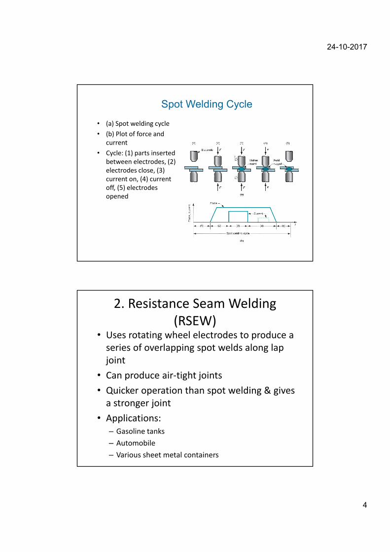
4. Resistance Projection Welding
(RPW)
• A resistance welding process in which
coalescence occurs at one or more small
contact points on the parts
• Contact points determined by design of parts
to be joined
– May consist of projections, embossments, or localized
intersections of parts
• The surfaces of the w/p are in contact only at the
projections.
24-10-2017
8
• (1) Start of operation, contact between parts
is at projections by pressing the upper
electrode downwards; (2) when current is
applied, weld nuggets similar to spot welding
are formed at the projections
Resistance Projection Welding
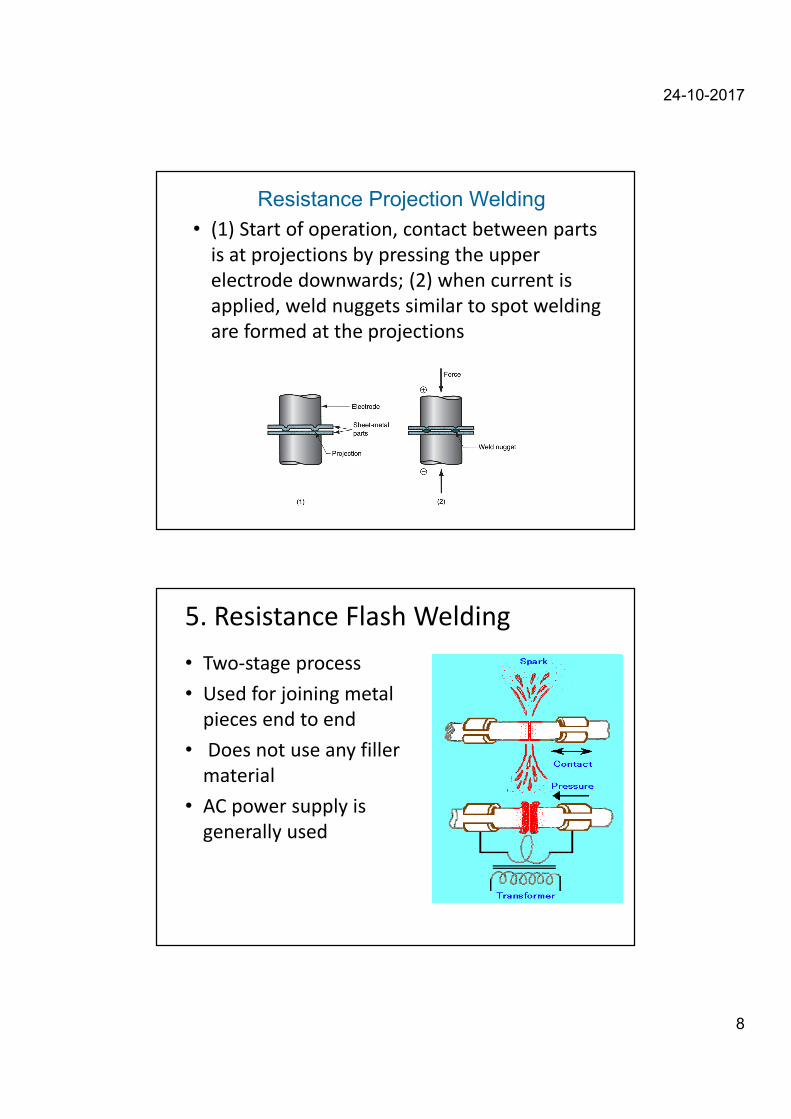
5. Resistance Flash Welding
• Two-stage process
• Used for joining metal
pieces end to end
• Does not use any filler
material
• AC power supply is
generally used

24-10-2017
9
Steps for Flash Welding-
1. First the current is switched ON
• Weld pieces are slowly brought together to
make end contact
• produces a flashing or arcing across the
interface of the two butting ends
2. Pieces are then forcibly press against each
other.
• This forces the molten metal & slag to be
squeezed out in the form of sparks
Application of Flash Welding
• Automobile industry
• Tubular and solid structures
• Welding of pipes
24-10-2017
10
Advantages of Flash welding-
• Much quicker than Butt welding
• As only a small portion of w/p is heated,
current consumption is less
• Stronger than the butt welding joints
Limitations-
• Upsetting pressure and power limit the size &
area of w/p
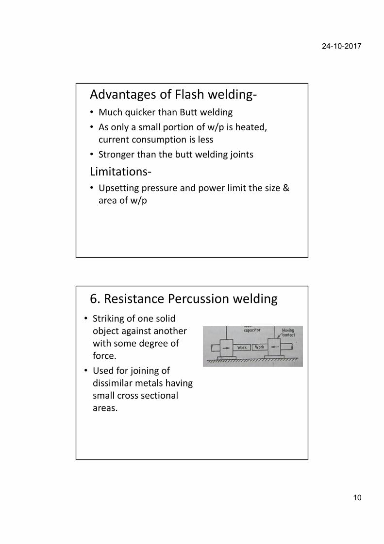
6. Resistance Percussion welding
• Striking of one solid
object against another
with some degree of
force.
• Used for joining of
dissimilar metals having
small cross sectional
areas.
24-10-2017
11
Steps for Percussion Welding-
• First hold the parts at a small distance
• Switch ON the current & bring them closer at
fast speed
• An arc will be generated just before the
contact
• Then the weld will be completed after impact
Soldering
• It is a low temperature joining process by using another
metal or alloy which has fairly low melting pt. as compared to
the metals to be joined. It is performed at temperatures
below 450° C for joining.
• Soldering is used for,
• Sealing, as in automotive radiators or tin cans
• Electrical Connections
• Joining dissimilar metals

24-10-2017
12
Soldering
• Soft soldering: is used for sheet metal works
that are not subjected to excessive loads,
these melt at temp below 350° C
– Alloy of lead & tin
• Hard Soldering: employed solders whose
melting temp. is higher than soft solders.
– Alloy of Cu & Zn
Solder = Filler metal
Soldering
Applications:
• Printed Circuit Board (PCB) manufacture
• Pipe joining (copper pipe)
• Jewelry manufacture
Easy to solder: copper, silver, gold
Difficult to solder: aluminum, stainless steels
• Alloys of Tin (silver, bismuth, lead)
Flux used to clean joint & prevent oxidation
• Typically non-load bearing
Tinning = pre-coating with thin layer of solder
• Zinc chloride
• separate or in core of wire

24-10-2017
13
• Low temperature joining process.
• It is performed at temperatures above 450° C and it generally
affords strengths comparable to those of the metal which it
joins.
• It is low temperature in that it is done below the melting point
of the base metal.
• It is achieved by diffusion without fusion (melting) of the base
Brazing
Brazing
Advantages
• Dissimilar metals which canot be welded can be joined by brazing
• Very thin metals can be joined
• Metals with different thickness can be joined easily
• In brazing thermal stresses are not produced in the work piece. Hence there is no distortion
• Using this process, carbides tips are brazed on the steel tool holders
Disadvantages
• Brazed joints have lesser strength compared to welding
• Joint preparation cost is more
• Can be used for thin sheet metal sections

24-10-2017
14
Use of low melt point filler metal to fill thin gap between
mating surfaces to be joined utilizing capillary action
Brazing
Applications:
• Pipe/Tubing joining (HVAC)
• Filler metals include Al, Mg & Cu alloys
• Automotive - joining tubes
• Electrical equipment - joining wires
• Jewelry Making
• Flux used (Borax)
• Types of brazing classified by heating
method:– Torch, Furnace, Resistance
• Joint can possess significant
strength
WELDING
DEFECTS

24-10-2017
15
Defects affect the quality of weld
• Porosity
• Poor penetration
• Warping
• Undercut & Underfill
• Distortion
• Cracked welds
• Poor appearance
• Poor fusion
• Brittle welds
• Spatter
• Magnetic blow
• Weld stress
Causes and cures of common welding troubles
Presence of small pores or voids in the weld, due to entrapement of gases.
When these pores are quite small – porosity
Bigger void- Blow Hole
Due to:-
1. Presence of oil, grease, moisture
2. Faulty electrodes
3. Improper gas shielding
4. Wrong welding techniques
5. Low welding current
Porosity
24-10-2017
16
Causes and cures of common welding troubles
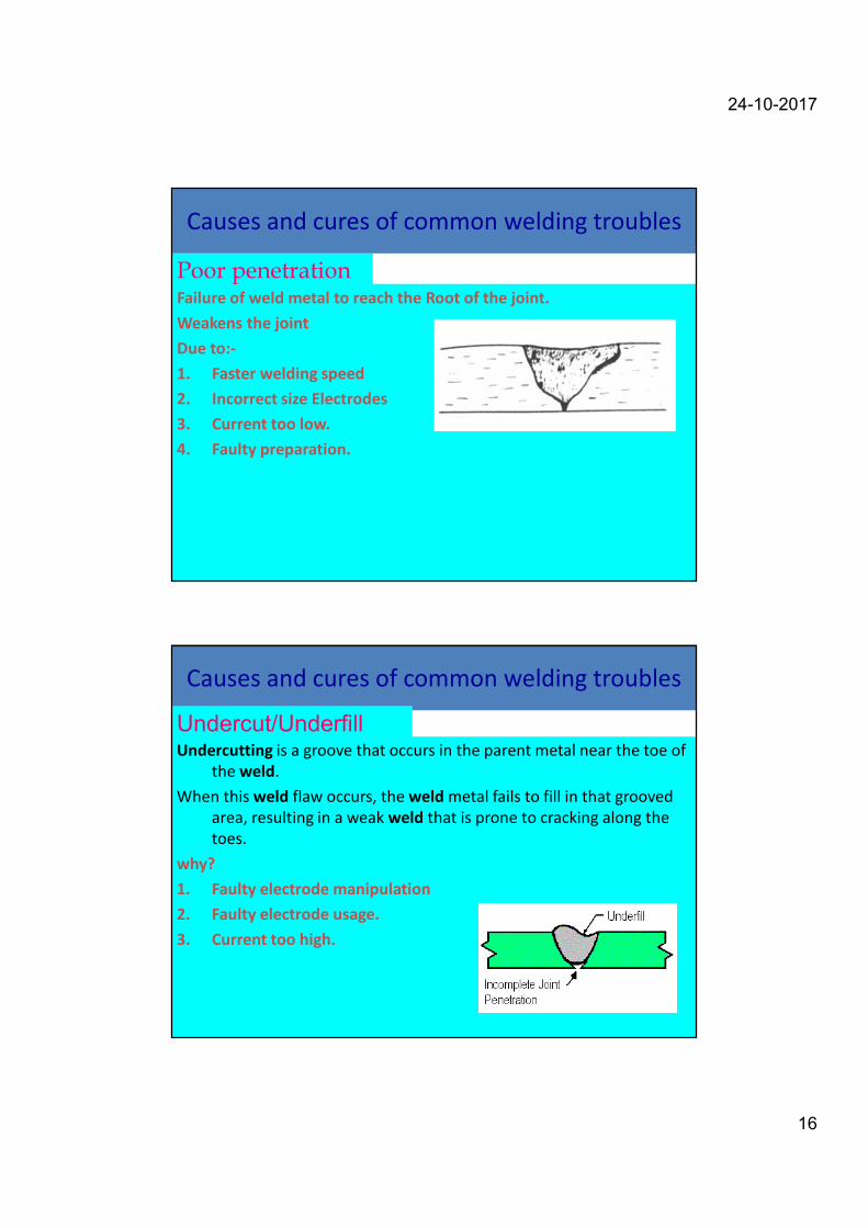
Failure of weld metal to reach the Root of the joint.
Weakens the joint
Due to:-
1. Faster welding speed
2. Incorrect size Electrodes
3. Current too low.
4. Faulty preparation.
Poor penetration
Causes and cures of common welding troubles
Undercutting is a groove that occurs in the parent metal near the toe of
the weld.
When this weld flaw occurs, the weld metal fails to fill in that grooved
area, resulting in a weak weld that is prone to cracking along the
toes.
why?
1. Faulty electrode manipulation
2. Faulty electrode usage.
3. Current too high.
Undercut/Underfill

24-10-2017
17
Causes and cures of common welding
troubles
Examples of various discontinuities in fusion welds
Fig. a) Underfill
Fig. a) Undercut
Causes and cures of common welding
troubles
• Slag got entrapped in the weld metal specially in case of Multi pass welds and is known as Slag Inclusion
• Such inclusion may also be added due to dirt, rust etc.
• Such inclusions weakens the weld.
Inclusions

24-10-2017
18
Causes and cures of common welding troubles
Due to:-
1. Uneven heat
2. Improper sequence.
3. Deposited metal shrinks.
Distortion
Causes and cures of common welding
troublesDistortion of parts after
welding
Fig. a) in butt joints
Fig. a) in fillet joints

24-10-2017
19
Causes and cures of common welding troubles
Crack is a discontinuity of metal.
• Macro crack
• Micro crack
Makes the joint weak and finally lead to fracture.
Due to:-
1. Wrong electrode.
2. Weld and part sizes unbalanced.
3. Faulty welds.
4. Faulty preparation.
5. Rigid joints.
Cracked welds
Cracks caused by thermal stresses
Types of cracks in welded joints caused by thermal stresses that develop
during solidification and contraction of the weld bead and the welded
structure .
Fig. a) Crater cracks
Fig. b) various types of cracks
in butt & T-joints

24-10-2017
20
Causes and cures of common welding
troubles
Tiny electrode metal particles are blown out of the arc which get deposited over the bead and base material.
Gives Poor appearance
Does not have any effect on weld strength
Due to:-
1. Too high welding current
2. Wrong composition of flux coating
3. Discontinuous Arc
Spatter
Causes and cures of common welding
troubles
Deposited weld metal by the electrode does not fuse fully with the base metal because the latter is relatively cooler.
Due to:-
1. Presence of oxide, dirt, scale, slag b/w to fusing surfaces
2. Wrong speed.
3. Current improperly adjusted.
Poor fusion

24-10-2017
21
Causes and cures of common welding troubles
Examples of various discontinuities
in fusion welds
Poor
fusion
Causes and cures of common welding
troubles
why?
1. Wrong electrode.
2. Faulty preheating.
3. Metal hardened by air.
What to do?
1. Preheat at 135 to 260º C if welding on medium-carbon steel or certain alloy steel.
2. Make multiple-layer welds.
3. Anneal after welding.
4. Use stainless or low-hydrogen electrodes for increasing weld ductility.
Brittle welds
24-10-2017
22
Causes and cures of common welding
troubles
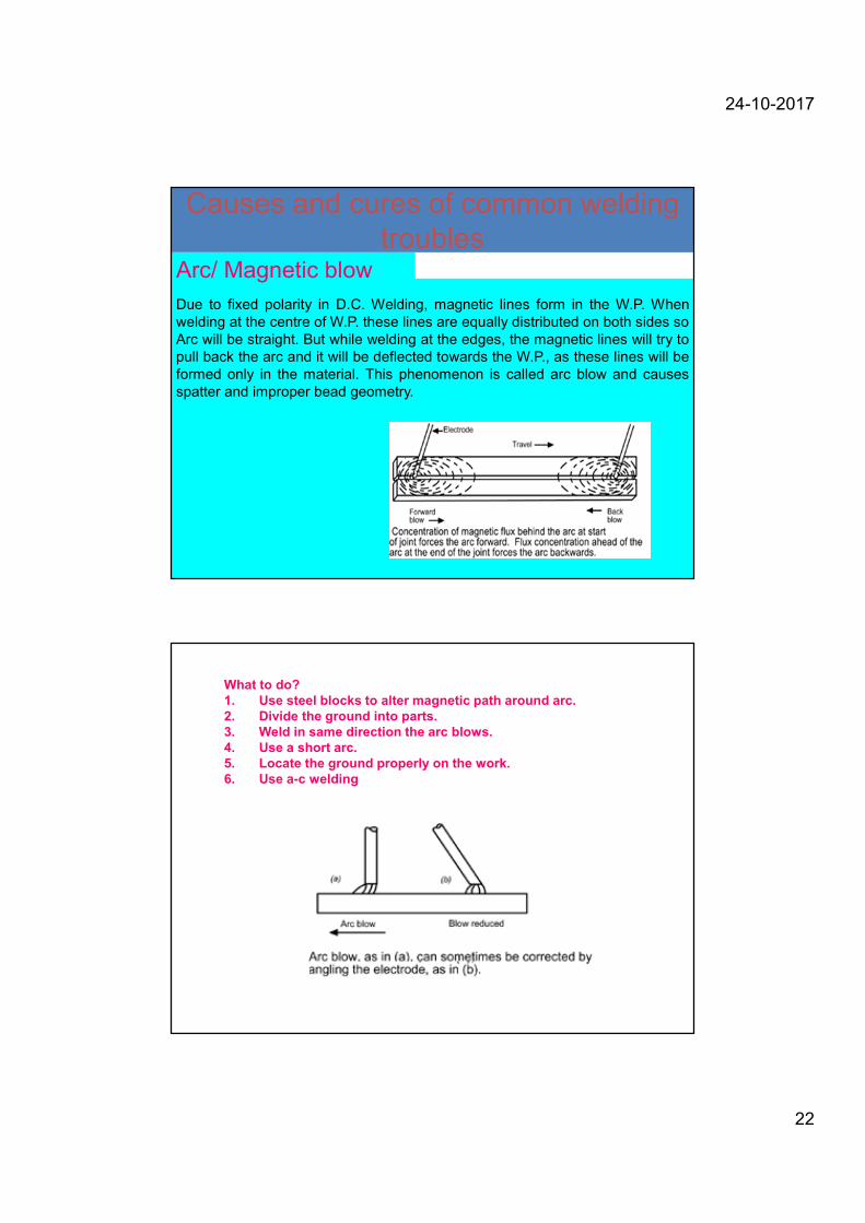
Due to fixed polarity in D.C. Welding, magnetic lines form in the W.P. When
welding at the centre of W.P. these lines are equally distributed on both sides so
Arc will be straight. But while welding at the edges, the magnetic lines will try to
pull back the arc and it will be deflected towards the W.P., as these lines will be
formed only in the material. This phenomenon is called arc blow and causes
spatter and improper bead geometry.
Arc/ Magnetic blow
What to do?
1. Use steel blocks to alter magnetic path around arc.
2. Divide the ground into parts.
3. Weld in same direction the arc blows.
4. Use a short arc.
5. Locate the ground properly on the work.
6. Use a-c welding

24-10-2017
23
Thank you
Related Documents