Citation: Mahmood, A.S.; Summerscales, J.; James, M.N. Resin-Rich Volumes (RRV) and the Performance of Fibre-Reinforced Composites: A Review. J. Compos. Sci. 2022, 6, 53. https://doi.org/10.3390/ jcs6020053 Academic Editor: Francesco Tornabene Received: 24 January 2022 Accepted: 7 February 2022 Published: 10 February 2022 Publisher’s Note: MDPI stays neutral with regard to jurisdictional claims in published maps and institutional affil- iations. Copyright: © 2022 by the authors. Licensee MDPI, Basel, Switzerland. This article is an open access article distributed under the terms and conditions of the Creative Commons Attribution (CC BY) license (https:// creativecommons.org/licenses/by/ 4.0/). Review Resin-Rich Volumes (RRV) and the Performance of Fibre-Reinforced Composites: A Review Amjed Saleh Mahmood 1,2 , John Summerscales 1, * and Malcolm Neil James 1,3 1 Materials and Structures (MAST) Research Group, School of Engineering, Computing and Mathematics (SECaM), Reynolds Building, University of Plymouth, Plymouth PL4 8AA, UK; [email protected] (A.S.M.); [email protected] (M.N.J.) 2 Electromechanical Engineering Department, University of Samarra, Samarra 34010, Salah al-Deen, Iraq 3 Department of Mechanical Engineering, Summerstrand Campus (North), Nelson Mandela Metropolitan University, Port Elizabeth 6031, South Africa * Correspondence: [email protected]; Tel.: +44-1752-5-86150 Abstract: This review considers the influence of resin-rich volumes (RRV) on the static and dynamic mechanical and physical behaviour of fibre-reinforced composites. The formation, shape and size, and measurement of RRV in composites, depending upon different fabric architectures and manufacturing processes, is discussed. The majority of studies show a negative effect of RRV on the mechanical behaviour of composite materials. The main factors that cause RRV are (a) the clustering of fibres as bundles in textiles, (b) the stacking sequence, (c) the consolidation characteristics of the reinforcement, (d) the resin flow characteristics as a function of temperature, and (e) the composite manufacturing process and cure cycle. RRV are stress concentrations that lead to a disproportionate decrease in composite strength. Those who are considering moving from autoclave consolidation to out-of- autoclave (OOA) processes should be cautious of the potential effects of this change. Keywords: composites; defects; fabric reinforcement; resin-rich volumes; voids 1. Introduction Recent decades have seen increasingly rapid advances in the field of fibre-reinforced composites. Pang and Bond [1] stated “that over 20 million tons [of fibre reinforced composites] are now produced every year for a variety of aerospace and other applications”. However, JEC Observer [2], likely using a limited definition, suggested the global composite market in 2020 to be just 10 million tonnes. The UK Composites Strategy 2016 [3] forecasts a tripling of the market between 2016–2030. The most significant reasons for this increasing demand for high-performance materials are that composites have a high modulus and/or strength-to-weight ratio, improved fatigue performance, high toughness, and durability in harsh environments. The aerospace industry is seeking cost reductions with out-of-autoclave prepreg (and possibly infusion) as target manufacturing routes. However, for any given reinforcement fabric, the achievable fibre volume fraction will decrease with the change from autoclave pressure (typically 5–7 bar) to a vacuum-only (<1 bar) consolidation processes. The power- law compressibility characteristics of the reinforcement could lead to a large increase in the resin fraction (a 10% decrease in fibre volume fraction is a 10% increase in the matrix volume fraction) arising from the adoption of out-of-autoclave (OOA) processes. This resin will cluster within and between the reinforcement layers. Many authors refer to resin-rich areas (RRA), resin-rich pockets (RRP), resin-rich regions (RRR) or resin-rich zones (RRZ), by implying 2D features as a consequence of image analysis using polished microscopical sections. The features are in reality three- dimensional; therefore, this review will use the technically correct and unambiguously 3D term resin-rich volumes (RRV). J. Compos. Sci. 2022, 6, 53. https://doi.org/10.3390/jcs6020053 https://www.mdpi.com/journal/jcs

Welcome message from author
This document is posted to help you gain knowledge. Please leave a comment to let me know what you think about it! Share it to your friends and learn new things together.
Transcript

�����������������
Citation: Mahmood, A.S.;
Summerscales, J.; James, M.N.
Resin-Rich Volumes (RRV) and the
Performance of Fibre-Reinforced
Composites: A Review. J. Compos. Sci.
2022, 6, 53. https://doi.org/10.3390/
jcs6020053
Academic Editor: Francesco
Tornabene
Received: 24 January 2022
Accepted: 7 February 2022
Published: 10 February 2022
Publisher’s Note: MDPI stays neutral
with regard to jurisdictional claims in
published maps and institutional affil-
iations.
Copyright: © 2022 by the authors.
Licensee MDPI, Basel, Switzerland.
This article is an open access article
distributed under the terms and
conditions of the Creative Commons
Attribution (CC BY) license (https://
creativecommons.org/licenses/by/
4.0/).
Review
Resin-Rich Volumes (RRV) and the Performance ofFibre-Reinforced Composites: A ReviewAmjed Saleh Mahmood 1,2, John Summerscales 1,* and Malcolm Neil James 1,3
1 Materials and Structures (MAST) Research Group, School of Engineering, Computing andMathematics (SECaM), Reynolds Building, University of Plymouth, Plymouth PL4 8AA, UK;[email protected] (A.S.M.); [email protected] (M.N.J.)
2 Electromechanical Engineering Department, University of Samarra, Samarra 34010, Salah al-Deen, Iraq3 Department of Mechanical Engineering, Summerstrand Campus (North), Nelson Mandela Metropolitan
University, Port Elizabeth 6031, South Africa* Correspondence: [email protected]; Tel.: +44-1752-5-86150
Abstract: This review considers the influence of resin-rich volumes (RRV) on the static and dynamicmechanical and physical behaviour of fibre-reinforced composites. The formation, shape and size, andmeasurement of RRV in composites, depending upon different fabric architectures and manufacturingprocesses, is discussed. The majority of studies show a negative effect of RRV on the mechanicalbehaviour of composite materials. The main factors that cause RRV are (a) the clustering of fibres asbundles in textiles, (b) the stacking sequence, (c) the consolidation characteristics of the reinforcement,(d) the resin flow characteristics as a function of temperature, and (e) the composite manufacturingprocess and cure cycle. RRV are stress concentrations that lead to a disproportionate decrease incomposite strength. Those who are considering moving from autoclave consolidation to out-of-autoclave (OOA) processes should be cautious of the potential effects of this change.
Keywords: composites; defects; fabric reinforcement; resin-rich volumes; voids
1. Introduction
Recent decades have seen increasingly rapid advances in the field of fibre-reinforcedcomposites. Pang and Bond [1] stated “that over 20 million tons [of fibre reinforcedcomposites] are now produced every year for a variety of aerospace and other applications”.However, JEC Observer [2], likely using a limited definition, suggested the global compositemarket in 2020 to be just 10 million tonnes. The UK Composites Strategy 2016 [3] forecastsa tripling of the market between 2016–2030. The most significant reasons for this increasingdemand for high-performance materials are that composites have a high modulus and/orstrength-to-weight ratio, improved fatigue performance, high toughness, and durability inharsh environments.
The aerospace industry is seeking cost reductions with out-of-autoclave prepreg (andpossibly infusion) as target manufacturing routes. However, for any given reinforcementfabric, the achievable fibre volume fraction will decrease with the change from autoclavepressure (typically 5–7 bar) to a vacuum-only (<1 bar) consolidation processes. The power-law compressibility characteristics of the reinforcement could lead to a large increase inthe resin fraction (a 10% decrease in fibre volume fraction is a 10% increase in the matrixvolume fraction) arising from the adoption of out-of-autoclave (OOA) processes. This resinwill cluster within and between the reinforcement layers.
Many authors refer to resin-rich areas (RRA), resin-rich pockets (RRP), resin-richregions (RRR) or resin-rich zones (RRZ), by implying 2D features as a consequence ofimage analysis using polished microscopical sections. The features are in reality three-dimensional; therefore, this review will use the technically correct and unambiguously 3Dterm resin-rich volumes (RRV).
J. Compos. Sci. 2022, 6, 53. https://doi.org/10.3390/jcs6020053 https://www.mdpi.com/journal/jcs
J. Compos. Sci. 2022, 6, 53 2 of 16
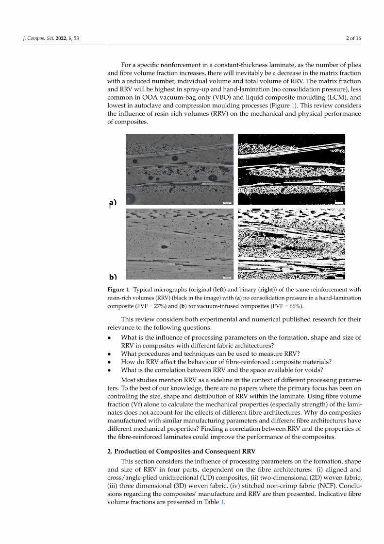
For a specific reinforcement in a constant-thickness laminate, as the number of pliesand fibre volume fraction increases, there will inevitably be a decrease in the matrix fractionwith a reduced number, individual volume and total volume of RRV. The matrix fractionand RRV will be highest in spray-up and hand-lamination (no consolidation pressure), lesscommon in OOA vacuum-bag only (VBO) and liquid composite moulding (LCM), andlowest in autoclave and compression moulding processes (Figure 1). This review considersthe influence of resin-rich volumes (RRV) on the mechanical and physical performanceof composites.
J. Compos. Sci. 2022, 6, x FOR PEER REVIEW 2 of 17
analysis using polished microscopical sections. The features are in reality three-dimen-
sional; therefore, this review will use the technically correct and unambiguously 3D term
resin-rich volumes (RRV).
For a specific reinforcement in a constant-thickness laminate, as the number of plies
and fibre volume fraction increases, there will inevitably be a decrease in the matrix frac-
tion with a reduced number, individual volume and total volume of RRV. The matrix
fraction and RRV will be highest in spray-up and hand-lamination (no consolidation pres-
sure), less common in OOA vacuum-bag only (VBO) and liquid composite moulding
(LCM), and lowest in autoclave and compression moulding processes (Figure 1). This re-
view considers the influence of resin-rich volumes (RRV) on the mechanical and physical
performance of composites.
Figure 1. Typical micrographs (original (left) and binary (right)) of the same reinforcement with
resin-rich volumes (RRV) (black in the image) with (a) no consolidation pressure in a hand-lamina-
tion composite (FVF = 27%) and (b) for vacuum-infused composites (FVF = 66%).
This review considers both experimental and numerical published research for their
relevance to the following questions:
• What is the influence of processing parameters on the formation, shape and size of
RRV in composites with different fabric architectures?
• What procedures and techniques can be used to measure RRV?
• How do RRV affect the behaviour of fibre-reinforced composite materials?
• What is the correlation between RRV and the space available for voids?
Most studies mention RRV as a sideline in the context of different processing param-
eters. To the best of our knowledge, there are no papers where the primary focus has been
on controlling the size, shape and distribution of RRV within the laminate. Using fibre
volume fraction (Vf) alone to calculate the mechanical properties (especially strength) of
the laminates does not account for the effects of different fibre architectures. Why do com-
posites manufactured with similar manufacturing parameters and different fibre architec-
tures have different mechanical properties? Finding a correlation between RRV and the
properties of the fibre-reinforced laminates could improve the performance of the compo-
sites.
Figure 1. Typical micrographs (original (left) and binary (right)) of the same reinforcement withresin-rich volumes (RRV) (black in the image) with (a) no consolidation pressure in a hand-laminationcomposite (FVF = 27%) and (b) for vacuum-infused composites (FVF = 66%).
This review considers both experimental and numerical published research for theirrelevance to the following questions:
• What is the influence of processing parameters on the formation, shape and size ofRRV in composites with different fabric architectures?
• What procedures and techniques can be used to measure RRV?• How do RRV affect the behaviour of fibre-reinforced composite materials?• What is the correlation between RRV and the space available for voids?
Most studies mention RRV as a sideline in the context of different processing parame-ters. To the best of our knowledge, there are no papers where the primary focus has been oncontrolling the size, shape and distribution of RRV within the laminate. Using fibre volumefraction (Vf) alone to calculate the mechanical properties (especially strength) of the lami-nates does not account for the effects of different fibre architectures. Why do compositesmanufactured with similar manufacturing parameters and different fibre architectures havedifferent mechanical properties? Finding a correlation between RRV and the properties ofthe fibre-reinforced laminates could improve the performance of the composites.
2. Production of Composites and Consequent RRV
This section considers the influence of processing parameters on the formation, shapeand size of RRV in four parts, dependent on the fibre architectures: (i) aligned andcross/angle-plied unidirectional (UD) composites, (ii) two-dimensional (2D) woven fabric,(iii) three dimensional (3D) woven fabric, (iv) stitched non-crimp fabric (NCF). Conclu-sions regarding the composites’ manufacture and RRV are then presented. Indicative fibrevolume fractions are presented in Table 1.

J. Compos. Sci. 2022, 6, 53 3 of 16
Table 1. Indicative fibre volume fractions for different reinforcements as a function of pressure.
Reinforcement Form No Consolidation(Zero Pressure)
Vacuum-Only(1 Bar)
Autoclave(5–7 Bar)
Random 2D 10% 20% 30%Woven 3D 30% 40% 55%Woven 2D 35% 45% 65%
Unidirectional 1D 50% 60% 80%
2.1. Aligned Unidirectional (UD), Cross-Plied (XP), and Angle-Plied (AP) UD Laminae
In UD (all fibres aligned parallel, although some definitions permit up to 30% fibresat 90◦), XP (fibres at 0◦ and 90◦) and AP (fibres normally at −45◦, 0◦, +45◦ and 90◦ to givequasi-isotropic properties) composites with unidirectional laminae, the RRV are caused bydifferent processing parameters which are related. Reducing compaction/consolidationpressure will reduce the fibre volume fraction (FVF) and resin flow and increase the RRVand voids [4]. Furthermore, the pore spaces in the dry reinforcement are filled with resinduring the flow, consolidation and cure processes to create the RRV [5]. The resin flow insome consolidation processes can displace fibres and create gaps that fill with resin to formthe RRV [6]. Gaps are also created due to the clustering of fibres to create space that thenbecomes the RRV [7]. External pressure compressed any voids within the matrix and coulddisperse the gasses and vapours in the matrix into the free volume between the moleculesof the polymer to produce a void-free matrix.
Sudarisman and Davies [4] prepared unidirectional carbon fibre by pre-impregnatingthe reinforcement with a solution of epoxy resin and hardener in acetone. High solute levelslead to FVF of 46.5%, whereas lower solute levels produced consistent FVF around 52.7%.UD composite plates manufactured and cured under vacuum in an autoclave producedlow-FVF composites with “matrix-rich regions between the individual prepreg layers”,poor plate flatness, poor bonding between the layers, and large voids in the RRV.
2.2. Two-Dimensional (2D) Woven Fabric
The difference between the processing parameters, which create RRV in 2D-wovenfabric (fabric architectures shown in the Figure in Section 3.1) and UD fabric, are relatedto fabric architecture. Increasing the manufacturing pressure, as mentioned in Section 2.1,reduces RRV, especially with autoclave consolidation [8,9], due to the nesting of fibres. RRVdepend on the design of the product, fibre layout or the stacking sequence. Costa et al. [10]consolidated 8-harness, satin-weave, prepreg carbon fibre laminates in a [0◦, 90◦]14 XPstacking sequence. RRV with voids were distributed at ply interfaces with cracks in RRVinitiated at the void tips.
Cartié et al. [11] studied the delamination of Z-pinned (unspecified materials) unidirec-tional versus woven-fabric, carbon-fibre-reinforced laminates and found RRV surroundingthe Z-pin. Failure micromechanisms in the test specimens were found to be dependent onthe architecture of the fibre reinforcement, for example: Z-pin debonding and pullout inMode I loading or Z-pins contributing to the crack opening displacement by pushing thecrack faces apart in Mode II loading. Holmberg and Berglund [12] manufactured U-beamswith 193 g/m2 plain-weave carbon fibre (Brochier Injectex GB200) oriented at ±45◦ andfound that the reinforcement pulled tight around the inner corners with consequent RRVon the outer surface.
The RRV in 12K T300 carbon fibre composites (reinforcement tape architecture notspecified) with modified montmorillonite nanoclay particles in a tetrafunctional TGDDMepoxy were found to mostly occur between the laminate plies. Large RRV were correlatedto a high resin viscosity when nanoparticles were included [13].
Herring and Fox [14] investigated the surface finish of carbon fibre epoxy compositeswith different fibre architectures (unidirectional and 2 × 2 twill) and SynSkin® surfacing
J. Compos. Sci. 2022, 6, 53 4 of 16
film cured using a rapid Quickstep™ procedure. High heating rates lead to low FVF, highresin content and increased surface roughness with porosity entrapment.
2.3. Three Dimensional (3D) Woven Fabric
In 3D woven fabric, the additional parameters (to those in UD- and 2D-woven fabric),which have a great effect on the distribution and size of RRV, include weave style anddistribution of the out-of-plane binder yarn reinforcement [15,16], binder yarn path [17,18]and level of compaction [15,17].
King et al. [19] identified that, in 3D-woven fabrics, the RRV associated with thethrough-the-thickness binder have a direct influence on mechanical properties and a signif-icant influence on damage development. King et al. [20] studied the influence of through-thickness binder yarn count in dry 3D carbon fibre fabrics on the prediction of FVF forfabric compaction and tow crimp. A smaller fibre count binder was expected to reduce theareal density, reduce the crimp within stuffer tows, and result in fewer RRV. Higher crimpwithin the through-the-thickness binders reduced the number and size of RRV.
Archer et al. [21] considered the effect of 3D weaving and consolidation on carbon fibretows, fabrics, and composites. They identified RRV around the binder which were smallerin layer-to-layer fabrics than in angle interlock, but layer-to-layer had a higher degree ofcrimp in the weft filler. The warp stuffer tows had a deformed lenticular shape, elongatingand conforming to the crimp of the weft filler tows. RRV were also seen between warpstuffers in the space where the binder would be on other weft layers. These RRV are aninevitable consequence with this design of fabric due to the binder pitch. Archer et al. [22]reported that weft stuffers can be pulled into the RRV between the warp stuffer stacks dueto the through-the-thickness binder. The weft stuffers “pinch the edges of the warp stuffertows distorting their shape and misaligning the warp stuffer stack”. The use of binderswith different tex values influences the size of the RRV.
Mahadik et al. [15] reported much larger RRV on the surface of the fabric where weaveryarns were absent above or below in order to close up the inter-yarn gaps under compaction.
2.4. Stitched Non-Crimp Fabric (NCF)
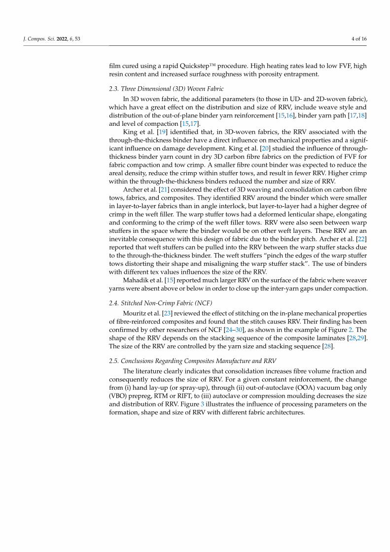
Mouritz et al. [23] reviewed the effect of stitching on the in-plane mechanical propertiesof fibre-reinforced composites and found that the stitch causes RRV. Their finding has beenconfirmed by other researchers of NCF [24–30], as shown in the example of Figure 2. Theshape of the RRV depends on the stacking sequence of the composite laminates [28,29].The size of the RRV are controlled by the yarn size and stacking sequence [28].
2.5. Conclusions Regarding Composites Manufacture and RRV
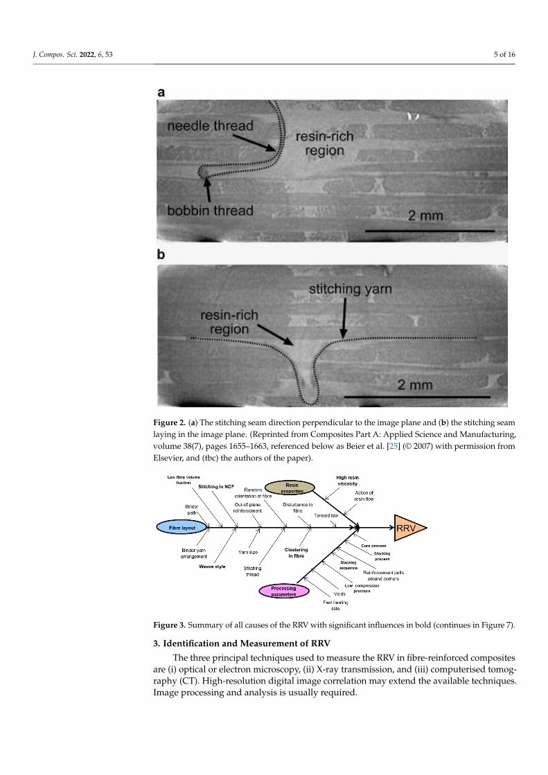
The literature clearly indicates that consolidation increases fibre volume fraction andconsequently reduces the size of RRV. For a given constant reinforcement, the changefrom (i) hand lay-up (or spray-up), through (ii) out-of-autoclave (OOA) vacuum bag only(VBO) prepreg, RTM or RIFT, to (iii) autoclave or compression moulding decreases the sizeand distribution of RRV. Figure 3 illustrates the influence of processing parameters on theformation, shape and size of RRV with different fabric architectures.
J. Compos. Sci. 2022, 6, 53 5 of 16J. Compos. Sci. 2022, 6, x FOR PEER REVIEW 5 of 17
Figure 2. (a) The stitching seam direction perpendicular to the image plane and (b) the stitching
seam laying in the image plane. (Reprinted from Composites Part A: Applied Science and Manufac-
turing, volume 38(7), pages 1655–1663, referenced below as Beier et al. [25] (© 2007) with permission
from Elsevier, and (tbc) the authors of the paper).
2.5. Conclusions Regarding Composites Manufacture and RRV
The literature clearly indicates that consolidation increases fibre volume fraction and
consequently reduces the size of RRV. For a given constant reinforcement, the change
from (i) hand lay-up (or spray-up), through (ii) out-of-autoclave (OOA) vacuum bag only
(VBO) prepreg, RTM or RIFT, to (iii) autoclave or compression moulding decreases the
size and distribution of RRV. Figure 3 illustrates the influence of processing parameters
on the formation, shape and size of RRV with different fabric architectures.
Figure 2. (a) The stitching seam direction perpendicular to the image plane and (b) the stitching seamlaying in the image plane. (Reprinted from Composites Part A: Applied Science and Manufacturing,volume 38(7), pages 1655–1663, referenced below as Beier et al. [25] (© 2007) with permission fromElsevier, and (tbc) the authors of the paper).
J. Compos. Sci. 2022, 6, x FOR PEER REVIEW 5 of 17
Figure 2. (a) The stitching seam direction perpendicular to the image plane and (b) the stitching
seam laying in the image plane. (Reprinted from Composites Part A: Applied Science and Manufac-
turing, volume 38(7), pages 1655–1663, referenced below as Beier et al. [25] (© 2007) with permission
from Elsevier, and (tbc) the authors of the paper).
2.5. Conclusions Regarding Composites Manufacture and RRV
The literature clearly indicates that consolidation increases fibre volume fraction and
consequently reduces the size of RRV. For a given constant reinforcement, the change
from (i) hand lay-up (or spray-up), through (ii) out-of-autoclave (OOA) vacuum bag only
(VBO) prepreg, RTM or RIFT, to (iii) autoclave or compression moulding decreases the
size and distribution of RRV. Figure 3 illustrates the influence of processing parameters
on the formation, shape and size of RRV with different fabric architectures.
Figure 3. Summary of all causes of the RRV with significant influences in bold (continues in Figure 7).
3. Identification and Measurement of RRV
The three principal techniques used to measure the RRV in fibre-reinforced compositesare (i) optical or electron microscopy, (ii) X-ray transmission, and (iii) computerised tomog-raphy (CT). High-resolution digital image correlation may extend the available techniques.Image processing and analysis is usually required.

J. Compos. Sci. 2022, 6, 53 6 of 16
3.1. Microscopic Image Analysis
Hayes [31] reviewed the optical microscopy of fibre-reinforced composites. Guild andSummerscales et al. [32–34] reviewed the use of computer-based image processing andanalysis in the microscopical study of fibre-reinforced composites. Such techniques provideaccess to spatial information on, and the quantification of, fibre distribution in addition tovolume fraction data.
Summerscales et al. [35] manufactured nine-layer unidirectional carbon-stitched fabriccomposite plates with cold-curing epoxy by wet lamination followed by vacuum bagging.They used different dwell times (0, 90 and 180 min) before applying vacuum pressure(0.8 bar) and found that fibre clustering and RRV were both lowest in the 90 min dwell plate.
Griffin et al. [36,37] studied commercial 2 × 2 twill carbon fibre flow-enhancementreinforcement fabrics (FERF) from Carr reinforcements woven with specially designedmesoscale architecture for RTM processes. An image analysis of optical micrographs wasused to quantify the micro-/meso-structures as statistical distributions of pore space areasand perimeters. An increased flow rate was shown to be related to the presence of bothmodest-sized and large pore spaces in the reinforcement architecture. The pore spacebecomes resin-rich volumes in the composites. The authors noted that these RRV may beimplicated in the premature mechanical failure of the laminate.
Pearce et al. [38] studied three Brochier (now Hexcel) carbon fibre fabrics: 5-harnesssatin (5HS), Injectex 5HS FERF and a 2 × 2 twill (Table 2 and Figure 4), with the samefibre type, surface treatment and FVF, to relate variations in permeability and mechanicalperformance to differences in the composite microstructures. The twill fabric (Figure 4a)had the smallest number of flow areas but a significant number of very large pore spaces(>0.5 mm2). The satin fabric (Figure 4b) had the highest proportion of small flow areas(<0.06 mm2). The Injectex (Figure 4c) had a significant number of pore space areas in therange 0.08–0.30 mm2. The proportion of larger pore spaces, and the consequent fabricpermeability were ranked twill > Injectex > satin, with the ranking of interlaminar shearstrength (ILSS) being in reverse order. Pearce et al. [39] continued to analyse the abovedata set using automated image analysis, specifically a fractal dimension, to quantify themicrostructure.
J. Compos. Sci. 2022, 6, x FOR PEER REVIEW 7 of 17
Figure 4. Schematics and transverse micrographs of Brochier weaves: (a) Injectex, (b) satin and (c)
twill. Image frame is 3.6 mm × 3.0 mm showing the different RRV dependent on weave style.
Canal et al. [41] consolidated 14-layer unidirectional laminates from prepreg sheets
of E- glass/MTM57 epoxy resin at 120 °C under 640 kPa autoclave pressure. Compression
tests were carried out within a scanning electron microscope and a digital image correla-
tion technique (DIC) with various magnifications (250×, 2000×, and 6000×) used to exam-
ine the differences in strains between the RRV and the fibre-rich volumes (FRV). They
found that the calculated strains from DIC measurement were in a good agreement with
the numerical results from a finite element model.
3.2. X-ray Transmission
This technique [42] projects X-rays toward the composite laminate surface, then cap-
tures the attenuated radiation on the opposite side by a detector to produce a 2D image of
the laminate structure. Tan et al. [43] used X-radiography to observe in-plane matrix
cracks and delamination propagation in NCF-stitched carbon fibre composites subjected
to impact loading. They consolidated AP stacking sequences with either
• 32-ply [+45°/90°/−45°/0°/(0°/+45°/90°/90°/−45°/0°)2]S, or
• 20-ply [+45°/90°/−45°/0°/0°/+45°/90°/90°/−45°/0°]S.
They conducted low-velocity, drop-weight impact tests with the drop height varied
to produce different impact energies. Using zinc iodide as a radio-opaque penetrant, the
radiographic images revealed that while through-thickness stitching greatly reduces de-
lamination growth, the RRV around stitch threads act as crack initiation sites.
3.3. Computerised Tomography (CT)
In X-ray CT scanning [44–47], the X-ray passes through a composite laminate from
different angles to create multiple images. These images can then be reconstructed to yield
an arbitrary slice or a full 3D image of the laminate showing the size and distribution of
the various phases including RRV or the voids. The process can be conducted at the
macro-scale, but in the context of composites is normally X-ray micro-computed tomog-
raphy (μCT).
Mahadik et al. [15] produced angle-interlock 3D-woven carbon fabric epoxy compo-
sites by RTM and measured the size and shape of the RRV using CT. They consolidated
samples with FVF from 50% to 65% with 5% increments. They found that the RRV size
Figure 4. Schematics and transverse micrographs of Brochier weaves: (a) Injectex, (b) satin and(c) twill. Image frame is 3.6 mm × 3.0 mm showing the different RRV dependent on weave style.

J. Compos. Sci. 2022, 6, 53 7 of 16
Table 2. Fabric description, the pore space area [38], and inter-laminar shear strength (ILSS) values-from ambient temperature experiments [40] for Brochier (now Hexcel)-woven carbon fibre fabrics.
Fabric Designation Description % BoundTows
Pore SpaceArea (mm2)
Ranked by ILSS(MPa)
Brochier E3853 G9866K carbon fibre fabric
290 g/m2 standard2 × 2 twill weave
0% >0.5 Lowest45.7 ± 1.3
Brochier E3833 G9636K carbon fibre fabric
290 g/m2 Injectex 5-harnesssatin weave with one in five bound tows
20% 0.08–0.30 Middle53.8 ± 1.7
Brochier E37956K carbon fibre fabric
290 g/m2 standard5-harness satin weave
0% <0.06 Highest58.2 ± 2.6
Canal et al. [41] consolidated 14-layer unidirectional laminates from prepreg sheetsof E-glass/MTM57 epoxy resin at 120 ◦C under 640 kPa autoclave pressure. Compressiontests were carried out within a scanning electron microscope and a digital image correlationtechnique (DIC) with various magnifications (250×, 2000×, and 6000×) used to examinethe differences in strains between the RRV and the fibre-rich volumes (FRV). They foundthat the calculated strains from DIC measurement were in a good agreement with thenumerical results from a finite element model.
3.2. X-ray Transmission
This technique [42] projects X-rays toward the composite laminate surface, then cap-tures the attenuated radiation on the opposite side by a detector to produce a 2D imageof the laminate structure. Tan et al. [43] used X-radiography to observe in-plane matrixcracks and delamination propagation in NCF-stitched carbon fibre composites subjected toimpact loading. They consolidated AP stacking sequences with either
• 32-ply [+45◦/90◦/−45◦/0◦/(0◦/+45◦/90◦/90◦/−45◦/0◦)2]S, or• 20-ply [+45◦/90◦/−45◦/0◦/0◦/+45◦/90◦/90◦/−45◦/0◦]S.
They conducted low-velocity, drop-weight impact tests with the drop height variedto produce different impact energies. Using zinc iodide as a radio-opaque penetrant,the radiographic images revealed that while through-thickness stitching greatly reducesdelamination growth, the RRV around stitch threads act as crack initiation sites.
3.3. Computerised Tomography (CT)
In X-ray CT scanning [44–47], the X-ray passes through a composite laminate fromdifferent angles to create multiple images. These images can then be reconstructed to yieldan arbitrary slice or a full 3D image of the laminate showing the size and distribution of thevarious phases including RRV or the voids. The process can be conducted at the macro-scale,but in the context of composites is normally X-ray micro-computed tomography (µCT).
Mahadik et al. [15] produced angle-interlock 3D-woven carbon fabric epoxy compos-ites by RTM and measured the size and shape of the RRV using CT. They consolidatedsamples with FVF from 50% to 65% with 5% increments. They found that the RRV size(0.2 mm3 to 12 mm3 for different fabrics) was inversely proportional to the level of com-paction. The average length of resin channels at 55% FVF was reduced by half when theFVF was increased by 5%.
Liotier et al. [28] claimed that CT could be successfully used to measure compositedefects in spite of the similar X-ray absorption of carbon fibres and epoxy resin. Theyused stitched NCF (Hexcel NC2® Non-Crimp New Concept) carbon fibre compositesas cylindrical samples with a radius of 10 mm and 2000 projections per full rotation(every 0.18◦). Their paper comprehensively describes the image processing and analysisprocedures. This procedure maximises the contrast between carbon fibres and epoxy, andhence improves the determination of RRV. The interlayer gaps were the main difficulty indefining the reference volume because of their differing shapes being dependent on stitch
J. Compos. Sci. 2022, 6, 53 8 of 16
loop geometry. RRV in multi-axial multi-ply stitched carbon composites manufactured byliquid resin infusion (LRI) averaged 3.0 ± 0.5% of the overall laminate volume.
Tan et al. [43] used CT to analyse defects and examine damage characteristics institched quasi-isotropic AP carbon fibre epoxy composites (as described at Section 3.2)subjected to impact loading. CT revealed that multiple cracks developed from the RRVaround the closely spaced stitch threads, leading to delamination.
Fritz et al. [48] used X-ray µCT with a 1 µm voxel size to quantify morphology inautoclaved AS4/8552 and in OOA IM7/M56 aerospace-grade unidirectional-ply carbonfibre prepreg composites, identifying misplaced microfibres and periodic “tow-alignedresin pockets (TARP)” parallel to the fibre direction adjacent to the interlaminar region.They also revealed high levels of previously unreported micro-voids with an averagevolume of 25 µm3.
4. Voids and Porosity
The pore space within a dry fabric may become RRV, and in turn may include voids(closed spaces) or porosity (inter-connected channels). Voids/porosity may include air orother volatile organic components (VOC). Subject to the resolution of the detection systemand the extent of sampling, the accuracy of void volume fraction (VVF) determinationis likely ± 0.5% [49]. Stone and Clarke [50] reported for VVF < 1.5% that voids tend tobe volatile-induced, and hence spherical with diameters in the range 5–20 µm, while forVVF > 1.5% the voids are flattened and elongated in the in-plane direction due to thelimitation of space between the fibre bundles. They are also significantly larger than forvoids at a lower VVF. Mayr et al. [51] have recently reported that small pores in CFRP withVVF < 1.8% often have roughly circular cross-sections and found an abrupt increase in theout-of-plane shape factors above this percentage porosity.
Judd and Wright [52] reviewed 47 papers and concluded that “although there is aconsiderable scatter in results (reflecting in part the difficulties of accurate void contentdetermination) the available data show that the interlaminar shear strength of compositesdecreases by about 7 per cent for each 1 per cent voids up to at least the 4 per cent voidcontent level, beyond which the rate of decrease diminishes. Other mechanical propertiesmay be affected to a similar extent. This is true for all composites regardless of the resin, fibreor fibre surface treatment used in their fabrication”. Table 1 of [52] presents a comprehensiveanalysis of the data. Similar findings were reported by Ghiorse [53].
Purslow [54] proposed a novel classification system for voids as the previous systemwas only applicable to fairly uniformly distributed voids. For example, to quote a VVFof 0.5% for a composite of generally high-quality (voids < 0.2%) but with an occasionalvery large void could be very misleading and potentially dangerous. He suggested that thevoid content should be quoted as “0 < voids < 0.2%; infrequent local voids > 0.5%”. Hisstudies suggested that when VVF < 0.5%, the voids are spherical with a diameter of 10 µmand are caused by trapped volatiles. As VVF increases, the voids decrease in number dueto trapped volatiles and are replaced by large intra-tow/intra-lamina voids. The resultssuggested a linear relationship between VVF and void thickness, where the thickness isrelated to fibre diameter.
Stringer [55] used hand lay-up with 340 g/m2 woven UD carbon fibre tape witha lightweight glass fibre weft in a [00/900]7 XP stacking sequence or with 472 g/m2
5-harness satin-weave carbon fibre fabric to manufacture composite laminates in epoxyresin. Increasing the epoxy viscosity to 7500–16,500 mPa.s by a dwell period before applyingthe vacuum pressure reduced the voids and improved the mechanical properties of thelaminates. In Section 3.1, there is further evidence that well-chosen dwell periods reducethe RRV [35].
Santulli et al. [49] used a microscopic image analysis to measure the void content intwill weave E-glass/polypropylene composites. They found that coplanar voids (voidsthat spread over the same plane, commonly corresponding to interlayer boundaries) existwhen RRV are detected between the laminae.

J. Compos. Sci. 2022, 6, 53 9 of 16
5. Evaluation of the Effects of RRV on Composite Performance
Studies normally show a negative effect of the RRV on the performance of the fibre-reinforced composites for all mechanical properties. This section is divided into four partsdealing with (i) static properties, (ii) dynamic properties, (iii) stress concentrations arisingfrom RRV, and (iv) crack initiation and propagation.
5.1. Static Properties
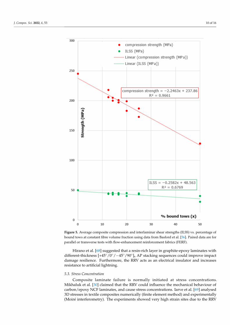
Numerous articles describe the effect of the RRV on the mechanical properties ofcomposites. Basford et al. [56] measured the compression and inter-laminar shear strengthsof carbon fibre/epoxy composite laminates reinforced with either normal 5-harness satin(5HS) or Injectex 5HS FERF woven fabrics at constant FVF. Both strengths were found todecrease as the proportion of flow-enhancement tows increased at constant FVF (Figure 5).The twisted tow (used to enhance flow rates in Injectex) was found to cause large RRVadjacent to the tow.
Hale [16] experimentally investigated the in-plane and out-of-plane strains of 5HS-woven carbon textile composites and found that the RRV have high local/microstructuraldistortions that differ from theoretical models for these sites.
Gojny et al. [57] studied the effect of carbon nanotubes on the mechanical properties ofglass-fibre-reinforced composites. They claimed that the RRV had a large local deformationrelative to the reinforcement as would be expected given the low elastic modulus of resin.
Tzetzis and Hogg [58] investigated an infusion repair technique that could increasethe toughness of carbon fibre laminates and reported a small reduction in load as presentedin a load/deflection curve, due to the damage in the RRV.
Vaughan and McCarthy [59] investigated the strain distribution in HTA/6376 UDprepreg carbon fibre-epoxy laminates (stacking sequence not revealed) at micro-scale andfound that transverse shear fracture bands propagated in the RRV. Liu and Liang [60]consolidated prepreg carbon/epoxy with an [0◦/−45◦/+45◦/90◦]s AP stacking sequenceand reported RRV in the layers adjacent to an embedded optical fibre.
Colin de Verdiere et al. [61] showed that the RRV reduced the in-plane stiffness of tuftednon-crimp fabric (NCF) composite materials by 13% relative to non-tufted reinforcement.
For natural fibre composites, Aziz and Ansell [62] investigated the effect of fibrealignment on the flexural properties of kenaf and hemp bast fibre composites. They foundthat the fibre alignment and the location of RRV both have a large negative effect on theflexural strength. Dhakal et al. [63] analysed the effect of water absorption on the tensileand flexural properties of hemp-fibre-reinforced composites. They found that the randomorientation of fibres could produce RRV, which could then reduce the mechanical propertiesof the fibres.
5.2. Dynamic Properties (Wave Propagation, Fatigue, Impact)
The RRV have a large effect on the dynamic properties of composites. Jeong andHsu [64] analysed wave propagation in carbon-fibre-reinforced composites and foundthat voids were localised in the RRV. Dyer et al. [65] studied the fatigue behaviour ofone plain weave, one biaxial stitch-bonded and one quasi-isotropic stitch-bonded glassfabric-reinforced composite. Damage occurred in the RRV where cracks initiated, and thenpropagated. Kalam et al. [66] studied the fatigue behaviour of oil palm fruit bunch (OPFB)fibre/epoxy and carbon fibre/epoxy composites and found damage initiated in the RRV.
Azouaoui et al. [67] investigated E-glass laminates with [(0◦/90◦)20◦]s stacking se-quence in impact fatigue and found that debonding and delamination cracks propagatedpreferentially through the interface at and in the RRV, respectively. Tan et al. [43] studiedthe materials described in Section 3.2 via impact loading and found that “stitches act ascrack initiation sites, due to the presence of weak [RRV] around stitch threads” with denselystitched composites showing more stitch-induced matrix cracks.
J. Compos. Sci. 2022, 6, 53 10 of 16
J. Compos. Sci. 2022, 6, x FOR PEER REVIEW 10 of 17
orientation of fibres could produce RRV, which could then reduce the mechanical prop-
erties of the fibres.
Figure 5. Average composite compression and interlaminar shear strengths (ILSS) vs. percentage of
bound tows at constant fibre volume fraction using data from Basford et al. [56]. Paired data are for
parallel or transverse tests with flow-enhancement reinforcement fabrics (FERF).
5.2. Dynamic Properties (Wave Propagation, Fatigue, Impact)
The RRV have a large effect on the dynamic properties of composites. Jeong and Hsu
[64] analysed wave propagation in carbon-fibre-reinforced composites and found that
voids were localised in the RRV. Dyer et al. [65] studied the fatigue behaviour of one plain
weave, one biaxial stitch-bonded and one quasi-isotropic stitch-bonded glass fabric-rein-
Figure 5. Average composite compression and interlaminar shear strengths (ILSS) vs. percentage ofbound tows at constant fibre volume fraction using data from Basford et al. [56]. Paired data are forparallel or transverse tests with flow-enhancement reinforcement fabrics (FERF).
Hirano et al. [68] suggested that a resin-rich layer in graphite-epoxy laminates withdifferent-thickness [+45◦/0◦/−45◦/90◦]s AP stacking sequences could improve impactdamage resilience. Furthermore, the RRV acts as an electrical insulator and increasesresistance to artificial lightning.
5.3. Stress Concentration
Composite laminate failure is normally initiated at stress concentrations.Mikhaluk et al. [30] claimed that the RRV could influence the mechanical behaviour ofcarbon/epoxy NCF laminates, and cause stress concentrations. Iarve et al. [69] analysed3D stresses in textile composites numerically (finite element method) and experimentally(Moiré interferometry). The experiments showed very high strain sites due to the RRV

J. Compos. Sci. 2022, 6, 53 11 of 16
(low elastic modulus resin) between the fibre tows. Dong [70] modelled the RRV in APglass fibre (351 g/m2) composite parts using basic mechanics and observed that the RRVcause a difference in mechanical behaviour from region to region within the laminate. Thisstudy used open channel moulds, and the experimental results show a 20% difference withthe model.
5.4. Crack Initiation and Propagation
In addition to the mechanical properties of composites, it is useful to investigate theeffect of RRV on crack behaviour. As indicated above, RRV are strongly implicated in theinitiation and propagation routes for crack growth [18,71–75], as shown in Figure 6. Thecracks move between plies through the RRV [29,72]. The RRV act to link cracks, with moreRRV leading to more micro-cracks [29] and the coherent fracture of the laminates in theRRV [76]. However, Liang et al. [77] stated that all cracks observed in their study werelocated at fibre/matrix interfaces, in fibre-rich volumes with almost no transverse cracksfound in RRV due to the weak transverse strength of flax/epoxy.
J. Compos. Sci. 2022, 6, x FOR PEER REVIEW 12 of 17
Figure 6. (a) Top view and (b) cross-sectional view of lock stitch pattern. (Reprinted from Materials
& Design, volume 35, pages 563–571 referenced below as Yudhanto et al. [75] (© 2012) with permis-
sion from Elsevier, and from Arief Yudhanto).
Henne et al. [78] introduced Grilon MS phenoxy binder yarn to stabilise the preform
before liquid composite moulding (LCM) processes. The yarn dissolves into the epoxy
resin behind the flow front; therefore, RRV are reduced, and hence less likely to initiate
microcracks.
Figure 7 summarises the effects of RRV on mechanical static and dynamic properties,
their stress concentrations and the crack behaviour of fibre-reinforced composites arising
from RRV.
Figure 7. The effects of the RRV on the mechanical behaviour of fibre-reinforced composites (con-
tinued from Figure 3).
Figure 6. (a) Top view and (b) cross-sectional view of lock stitch pattern. (Reprinted from Materials &Design, volume 35, pages 563–571 referenced below as Yudhanto et al. [75] (© 2012) with permissionfrom Elsevier, and from Arief Yudhanto).
Henne et al. [78] introduced Grilon MS phenoxy binder yarn to stabilise the pre-form before liquid composite moulding (LCM) processes. The yarn dissolves into theepoxy resin behind the flow front; therefore, RRV are reduced, and hence less likely toinitiate microcracks.
Figure 7 summarises the effects of RRV on mechanical static and dynamic properties,their stress concentrations and the crack behaviour of fibre-reinforced composites arisingfrom RRV.

J. Compos. Sci. 2022, 6, 53 12 of 16
J. Compos. Sci. 2022, 6, x FOR PEER REVIEW 12 of 17
Figure 6. (a) Top view and (b) cross-sectional view of lock stitch pattern. (Reprinted from Materials
& Design, volume 35, pages 563–571 referenced below as Yudhanto et al. [75] (© 2012) with permis-
sion from Elsevier, and from Arief Yudhanto).
Henne et al. [78] introduced Grilon MS phenoxy binder yarn to stabilise the preform
before liquid composite moulding (LCM) processes. The yarn dissolves into the epoxy
resin behind the flow front; therefore, RRV are reduced, and hence less likely to initiate
microcracks.
Figure 7 summarises the effects of RRV on mechanical static and dynamic properties,
their stress concentrations and the crack behaviour of fibre-reinforced composites arising
from RRV.
Figure 7. The effects of the RRV on the mechanical behaviour of fibre-reinforced composites (con-
tinued from Figure 3).
Figure 7. The effects of the RRV on the mechanical behaviour of fibre-reinforced composites (contin-ued from Figure 3).
6. Numerical Analysis
Mesomechanics is the area that bridges the microstructure–macroproperty relationshipof materials with non-continuum mechanics. Lomov et al. [79] carried out a full-field strainmeasurement on the surface of carbon fabric textile composites with meso-scale finiteelement modelling. In single-layer plain-weave carbon epoxy composites, the “lowesttensile strain value occurs not in the middle of the warp yarn but in the [RRV]”. Shearconcentration in the RRV between the yarns was captured by the simulation.
Heß and Himmel [80] simulated the experimental results of non-crimp fabric (NCF)carbon fibre/epoxy laminates under in-plane tension, compression and shear loading byusing the finite element method. The overall mean deviation between the experimentand simulation was 8–13%. Fibre dislocation and RRV were found to reduce the lami-nate strength.
Ghayoor et al. [81] used a finite element analysis of representative volume elements(RVE) to model the effects of interlaminar and intralaminar RRV on the transverse stiffnessand failure initiation of carbon epoxy composites. The analysis was performed using100 different computer-simulated microstructures with geometrically varying RRV. Forsamples at constant FVF, the presence of intra-laminar RRV reduced the average failureinitiation strains in the matrix by ~20%.
7. Conclusions
RRV have a significant effect on the mechanical behaviour of fibre-reinforced com-posites. The main techniques for measurement of RRV in fibre-reinforced compositesare microscopic image analysis, X-ray transmission, and computerised tomography (CT).High-resolution digital image correlation may extend the available techniques. RRV mayoccupy 3.0 ± 0.5% of the total laminate volume. One study found that the individualRRV size was 0.2 mm3 to 12 mm3 for different fabrics. The main causes of the RRV arethe fibre architecture, the resin properties and the processing parameters. Crack initiationand propagation are linked to the presence of RRV. The RRV negatively affect the staticproperties, the dynamic properties, the crack behaviour and stress concentration of fibrereinforced composites. One study showed that the resin-rich layer could be used as aninsulator to protect against lightning.
As a consequence of the above, the authors caution against reducing the consolidationpressure and changing the fibre architectures for high-performance composite structuresunless the effect of reduced FVF and the consequent RRV are fully understood for thereinforcement system being used.

J. Compos. Sci. 2022, 6, 53 13 of 16
8. Recommendations for Future Work
i. Future studies of RRV, manufacturing different laminates with similar manufacturingparameters and different fibre architectures could be useful to correlate RRV with thestatic and dynamic (fatigue and impact) properties of fibre-reinforced composites;
ii. A comparative study of the effect of the RRV on the mechanical properties of fibre-reinforced composites with other parameters such as FVF, crimp or stitching distribu-tion;
iii. Modified fibre architectures could reduce the RRV and improve the performance offibre-reinforced composites;
iv. Explore high-resolution digital image correlation techniques to visualise strain fieldinhomogeneity at RRV.
Author Contributions: Conceptualization, A.S.M. and J.S.; Methodology, A.S.M. and J.S.; Writing—Original Draft Preparation, A.S.M.; Writing—Review and Editing, A.S.M., J.S. and M.N.J.; Supervision,J.S. and M.N.J.; Project Administration, J.S. and M.N.J.; Funding Acquisition, A.S.M. All authors haveread and agreed to the published version of the manuscript.
Funding: Amjed Saleh Mahmood is grateful to the Iraqi government and the Ministry of HigherEducation and Scientific Research MOHESR for funding his doctoral studies at the Universityof Plymouth.
Data Availability Statement: This paper reviews the open scientific literature and assumes that thedata behind each cited paper is in the respective institutional repositories.
Conflicts of Interest: The authors declare no conflict of interest.
References1. Pang, J.W.C.; Bond, I.P. A hollow fibre reinforced polymer composite encompassing self-healing and enhanced damage visibility.
Compos. Sci. Technol. 2005, 65, 1791–1799. [CrossRef]2. JEC Group and Estin &, Co. Current Trends in the Global Composites Industry 2020–2025; JEC Observer, JEC: Paris, France, 2021.3. CLF. The Composites Strategy 2016: Lightening the Load; Composites Leadership Forum (CLF): Hemel Hemstead, UK, 2016.4. Sudarisman; Davies, I.J. The effect of processing parameters on the flexural properties of unidirectional carbon fibre-reinforced
polymer (CFRP) composites. Mater. Sci. Eng. A 2008, 498, 65–68. [CrossRef]5. Davies, L.W.; Day, R.J.; Bond, D.; Nesbitt, A.; Ellis, J.; Gardon, E. Effect of cure cycle heat transfer rates on the physical and
mechanical properties of an epoxy matrix composite. Compos. Sci. Technol. 2007, 67, 1892–1899. [CrossRef]6. Potter, K.; Khan, B.; Wisnom, M.; Bell, T.; Stevens, J. Variability, fibre waviness and misalignment in the determination of the
properties of composite materials and structures. Compos. Part A Appl. Sci. Manuf. 2008, 39, 1343–1354. [CrossRef]7. Williams, G.; Trask, R.; Bond, I. A self-healing carbon fibre reinforced polymer for aerospace applications. Compos. Part A Appl.
Sci. Manuf. 2007, 38, 1525–1532. [CrossRef]8. Abraham, D.; Matthews, S.; McIlhagger, R. A comparison of physical properties of glass fibre epoxy composites produced by wet
lay-up with autoclave consolidation and resin transfer moulding. Compos. Part A Appl. Sci. Manuf. 1998, 29, 795–801. [CrossRef]9. Botelho, E.; Rezende, M.; Mayer, S.; Voorwald, H. Evaluation of fatigue behavior on repaired carbon fiber/epoxy composites.
J. Mater. Sci. 2008, 43, 3166–3172. [CrossRef]10. Costa, M.L.; de Almeida, S.F.M.; Rezende, M.C. The influence of porosity on the interlaminar shear strength of carbon/epoxy and
carbon/bismaleimide fabric laminates. Compos. Sci. Technol. 2001, 61, 2101–2108. [CrossRef]11. Cartié, D.D.R.; Troulis, M.; Partridge, I.K. Delamination of Z-pinned carbon fibre reinforced laminates. Compos. Sci. Technol. 2006,
66, 855–861. [CrossRef]12. Holmberg, J.A.; Berglund, L.A. Manufacturing and performance of RTM U-beams. Compos. Part A Appl. Sci. Manuf. 1997, 28,
513–521. [CrossRef]13. Xu, Y.; Hoa, S.V. Mechanical properties of carbon fiber reinforced epoxy/clay nanocomposites. Compos. Sci. Technol. 2008, 68,
854–861. [CrossRef]14. Herring, M.L.; Fox, B.L. The effect of a rapid curing process on the surface finish of a carbon fibre epoxy composite. Compos. Part
B Eng. 2011, 42, 1035–1043. [CrossRef]15. Mahadik, Y.; Brown, K.A.R.; Hallett, S.R. Characterisation of 3D woven composite internal architecture and effect of compaction.
Compos. Part A Appl. Sci. Manuf. 2010, 41, 872–880. [CrossRef]16. Hale, R.D. An experimental investigation into strain distribution in 2D and 3D textile composites. Compos. Sci. Technol. 2003, 63,
2171–2185. [CrossRef]17. Bannister, M.; Herszberg, I.; Nicolaidis, A.; Coman, F.; Leong, K.H. The manufacture of glass/epoxy composites with multilayer
woven architectures. Compos. Part A Appl. Sci. Manuf. 1998, 29, 293–300. [CrossRef]

J. Compos. Sci. 2022, 6, 53 14 of 16
18. Callus, P.J.; Mouritz, A.P.; Bannister, M.K.; Leong, K.H. Tensile properties and failure mechanisms of 3D woven GRP composites.Compos. Part A Appl. Sci. Manuf. 1999, 30, 1277–1287. [CrossRef]
19. King, R.S.; Stewart, G.; McIlhagger, A.T.; Quinn, J.P. Incremental damage development in a 3D woven carbon fibre Composite.Polym. Polym. Compos. 2007, 15, 521–533. [CrossRef]
20. King, R.S.; Stewart, G.; McIlhagger, A.T.; Quinn, J.P. The influence of through-the-thickness binder yarn count on fibre volumefraction, crimp and damage tolerance within 3D woven carbon fibre Composites. Polym. Polym. Compos. 2009, 17, 303–312.[CrossRef]
21. Archer, E.; Buchanan, S.; McIlhagger, A.T.; Quinn, J.P. The effect of 3D weaving and consolidation on carbon fiber tows, fabrics,and composites. J. Reinf. Plast. Compos. 2010, 29, 3162–3170. [CrossRef]
22. Archer, E.; King, S.; Quinn, J.P.; Buchanan, S.; McIlhagger, A.T. Impact damage analysis of 3D woven carbon fibre compositesusing computed tomography. In Proceedings of the 18th International Conference of Composite Materials, Jeju Island, Korea,21–26 August 2011. W2-3-AF0217.
23. Mouritz, A.P.; Leong, K.H.; Herszberg, I. A review of the effect of stitching on the in-plane mechanical properties of fibre-reinforcedpolymer composites. Compos. Part A Appl. Sci. Manuf. 1997, 28, 979–991. [CrossRef]
24. Aymerich, F.; Priolo, P.; Sun, C.T. Static and fatigue behaviour of stitched graphite/epoxy composite laminates. Compos. Sci.Technol. 2003, 63, 907–917. [CrossRef]
25. Beier, U.; Fischer, F.; Sandler, J.K.W.; Altstädt, V.; Weimer, C.; Buchs, W. Mechanical performance of carbon fibre-reinforcedcomposites based on stitched preforms. Compos. Part A Appl. Sci. Manuf. 2007, 38, 1655–1663. [CrossRef]
26. Truong, T.C.; Vettori, M.; Lomov, S.; Verpoest, I. Carbon composites based on multi-axial multi-ply stitched preforms. Part 4.Mechanical properties of composites and damage observation. Compos. Part A Appl. Sci. Manuf. 2005, 36, 1207–1221. [CrossRef]
27. Garschke, C.; Weimer, C.; Parlevliet, P.P.; Fox, B.L. Out-of-autoclave cure cycle study of a resin film infusion process using in situprocess monitoring. Compos. Part A Appl. Sci. Manuf. 2012, 43, 935–944. [CrossRef]
28. Liotier, P.-J.; Alain, V.; Christine, D. Characterization of 3D morphology and microcracks in composites reinforced by multi-axialmulti-ply stitched preforms. Compos. Part A Appl. Sci. Manuf. 2010, 41, 653–662. [CrossRef]
29. Liotier, P.-J.; Vautrin, A.; Beraud, J.-M. Microcracking of composites reinforced by stitched multiaxials subjected to cyclicalhygrothermal loadings. Compos. Part A Appl. Sci. Manuf. 2011, 42, 425–437. [CrossRef]
30. Mikhaluk, D.S.; Truong, T.C.; Borovkov, A.I.; Lomov, S.V.; Verpoest, I. Experimental observations and finite element modelling ofdamage initiation and evolution in carbon/epoxy non-crimp fabric composites. Eng. Fract. Mech. 2008, 75, 2751–2766. [CrossRef]
31. Hayes, B.S.; Gammon, L.M. Optical Microscopy of Fiber-Reinforced Composites; ASM International: Materials Park, OH, USA, 2011;ISBN 978-1-61503-044-6.
32. Guild, F.J.; Summerscales, J. Microstructural image analysis applied to fibre composite materials: A review. Composites 1993, 24,383–393. [CrossRef]
33. Summerscales, J. Microstructural Characterisation of Fibre-Reinforced Composites; Woodhead Publishing: Cambridge, UK, 1998;ISBN 978-1-85573-240-7. [CrossRef]
34. Summerscales, J.; Guild, F.J.; Pearce, N.R.L.; Russell, P.M. Voronoi cells, fractal dimensions and fibre composites. J. Microsc. 2001,201, 153–162. [CrossRef]
35. Summerscales, J.; Green, D.; Guild, F.J. Effect of processing dwell-time on the microstructure of a fibre-reinforced composite.J. Microsc. 1993, 169, 173–182. [CrossRef]
36. Griffin, P.R.; Grove, S.M.; Guild, F.J.; Russell, P.; Summerscales, J. The effect of microstructure on flow promotion in resin transfermoulding reinforcement fabrics. J. Microsc. 1995, 177, 207–217. [CrossRef]
37. Griffin, P.R.; Grove, S.M.; Russell, P.; Short, D.; Summerscales, J. The effect of reinforcement architecture on the long-range flow infibrous reinforcements. Compos. Manuf. 1995, 6, 221–235. [CrossRef]
38. Pearce, N.R.L.; Guild, F.J.; Summerscales, J. An investigation into the effects of fabric architecture on the processing and propertiesof fibre reinforced composites produced by resin transfer moulding. Compos. Part A Appl. Sci. Manuf. 1998, 29, 19–27. [CrossRef]
39. Pearce, N.R.L.; Guild, F.J.; Summerscales, J. The use of automated image analysis for the investigation of fabric architecture on theprocessing and properties of fibre-reinforced composites produced by RTM. Compos. Part A Appl. Sci. Manuf. 1998, 29, 829–837.[CrossRef]
40. Pearce, N.R.L.; Guild, F.J.; Summerscales, J. A study of the effects of convergent flow fromts on the properties of fibre reinforcedcomposites produced by RTM. Compos. Part A Appl. Sci. Manuf. 1998, 29, 141–152. [CrossRef]
41. Canal, L.P.; González, C.; Molina-Aldareguía, J.M.; Segurado, J.; Llorca, J. Application of digital image correlation at the microscalein fiber-reinforced composites. Compos. Part A Appl. Sci. Manuf. 2012, 43, 1630–1638. [CrossRef]
42. Birt, E.A. Applicability of X-radiography to the inspection of composites. Insight Non-Destr. Test. Cond. Monit. 2000, 42, 152–157.43. Tan, K.T.; Watanabe, N.; Iwahori, Y. X-ray radiography and micro-computed tomography examination of damage characteristics
in stitched composites subjected to impact loading. Compos. Part B Eng. 2011, 42, 874–884. [CrossRef]44. Garcea, S.C.; Wang, Y.; Withers, P.J. X-ray computed tomography of polymer composites. Compos. Sci. Technol. 2018, 156, 305–319.
[CrossRef]45. Naresh, K.; Khan, K.A.; Umer, R.; Cantwell, W.J. The use of X-ray computed tomography for design and process modeling of
aerospace composites: A review. Mater. Des. 2020, 190, 108553. [CrossRef]
J. Compos. Sci. 2022, 6, 53 15 of 16
46. Rashidi, A.; Olfatbakhsh, T.; Crawford, B.; Milani, A.S. A review of current challenges and case study toward optimizingmicro-computed X-ray tomography of carbon fabric Composites. Materials 2020, 13, 3606. [CrossRef]
47. Gao, Y.; Hu, W.; Xin, S.; Sun, L. A review of applications of CT imaging on fiber reinforced composites. J. Compos. Mater. 2021, 56,133–164. [CrossRef]
48. Fritz, N.K.; Kopp, R.; Nason, A.K.; Ni, X.; Lee, J.; Stein, I.Y.; Kalfon-Cohen, E.; Sinclair, I.; Spearing, S.M.; Camanho, P.P.; et al.New interlaminar features and void distributions in advanced aerospace-grade composites revealed via automated algorithmsusing micro-computed tomography. Compos. Sci. Technol. 2020, 193, 108132. [CrossRef]
49. Santulli, C.; Gil, R.G.; Long, A.; Clifford, M. Void content measurements in commingled E-glass/polypropylene composites usingimage analysis from optical Micrographs. Sci. Eng. Compos. Mater. 2002, 10, 77–90. [CrossRef]
50. Stone, D.; Clarke, B. Ultrasonic attenuation as a measure of void content in carbon-fibre reinforced plastics. Non-Destr. Test. 1975,8, 137–145. [CrossRef]
51. Mayr, G.; Plank, B.; Sekelja, J.; Hendorfer, G. Active thermography as a quantitative method for non-destructive evaluation ofporous carbon fiber reinforced polymers. NDT E Int. 2011, 44, 537–543. [CrossRef]
52. Judd, N.C.W.; Wright, W. Voids and their effects on the mechanical properties of composites—An appraisal. SAMPE J. 1978, 14,10–14.
53. Ghiorse, S. Effect of void content on the mechanical properties of carbon/epoxy laminates. SAMPE Q. 1993, 24, 54–59.54. Purslow, D. On the optical assessment of the void content in composite materials. Composites 1984, 15, 207–210. [CrossRef]55. Stringer, L.G. Optimization of the wet lay-up/vacuum bag process for the fabrication of carbon fibre epoxy composites with high
fibre fraction and low void content. Composites 1989, 20, 441–452. [CrossRef]56. Basford, D.M.; Griffin, P.R.; Grove, S.M.; Summerscales, J. Relationship between mechanical performance and microstructure in
composites fabricated with flow-enhancing fabrics. Composites 1995, 26, 675–679. [CrossRef]57. Gojny, F.H.; Wichmann, M.H.G.; Fiedler, B.; Bauhofer, W.; Schulte, K. Influence of nano-modification on the mechanical and
electrical properties of conventional fibre-reinforced composites. Compos. Part A Appl. Sci. Manuf. 2005, 36, 1525–1535. [CrossRef]58. Tzetzis, D.; Hogg, P.J. Bondline toughening of vacuum infused composite repairs. Compos. Part A Appl. Sci. Manuf. 2006, 37,
1239–1251. [CrossRef]59. Vaughan, T.J.; McCarthy, C.T. A micromechanical study on the effect of intra-ply properties on transverse shear fracture in fibre
reinforced composites. Compos. Part A Appl. Sci. Manuf. 2011, 42, 1217–1228. [CrossRef]60. Liu, R.M.; Liang, D.K. Experimental study of carbon fiber reinforced plastic with embedded optical fibers. Mater. Des. 2010, 31,
994–998. [CrossRef]61. Colin de Verdiere, M.; Pickett, A.K.; Skordos, A.A.; Witzel, V. Evaluation of the mechanical and damage behaviour of tufted non
crimped fabric composites using full field measurements. Compos. Sci. Technol. 2009, 69, 131–138. [CrossRef]62. Aziz, S.H.; Ansell, M.P. The effect of alkalization and fibre alignment on the mechanical and thermal properties of kenaf and
hemp bast fibre composites: Part 1-polyester resin matrix. Compos. Sci. Technol. 2004, 64, 1219–1230. [CrossRef]63. Dhakal, H.N.; Zhang, Z.Y.; Richardson, M.O.W. Effect of water absorption on the mechanical properties of hemp fibre reinforced
unsaturated polyester composites. Compos. Sci. Technol. 2007, 67, 1674–1683. [CrossRef]64. Jeong, H.; Hsu, D.K. Experimental analysis of porosity-induced ultrasonic attenuation and velocity change in carbon composites.
Ultrasonics 1995, 33, 195–203. [CrossRef]65. Dyer, K.P.; Isaac, D.H. Fatigue behaviour of continuous glass fibre reinforced composites. Compos. Part B Eng. 1998, 29, 725–733.
[CrossRef]66. Kalam, A.; Sahari, B.B.; Khalid, Y.A.; Wong, S.V. Fatigue behaviour of oil palm fruit bunch fibre/epoxy and carbon fibre/epoxy
composites. Compos. Struct. 2005, 71, 34–44. [CrossRef]67. Azouaoui, K.; Azari, Z.; Pluvinage, G. Evaluation of impact fatigue damage in glass/epoxy composite laminate. Int. J. Fatigue
2010, 32, 443–452. [CrossRef]68. Hirano, Y.; Katsumata, S.; Iwahori, Y.; Todoroki, A. Artificial lightning testing on graphite/epoxy composite laminate. Compos.
Part A Appl. Sci. Manuf. 2010, 41, 1461–1470. [CrossRef]69. Iarve, E.V.; Mollenhauer, D.H.; Zhou, E.G.; Breitzman, T.; Whitney, T.J. Independent mesh method-based prediction of local and
volume average fields in textile composites. Compos. Part A Appl. Sci. Manuf. 2009, 40, 1880–1890. [CrossRef]70. Dong, C. Model development for the formation of resin-rich zones in composites processing. Compos. Part A Appl. Sci. Manuf.
2011, 42, 419–424. [CrossRef]71. Singh, S.; Partridge, I.K. Mixed-mode fracture in an interleaved carbon-fibre/epoxy composite. Compos. Sci. Technol. 1995, 55,
319–327. [CrossRef]72. Chambers, A.R.; Earl, J.S.; Squires, C.A.; Suhot, M.A. The effect of voids on the flexural fatigue performance of unidirectional
carbon fibre composites developed for wind turbine applications. Int. J. Fatigue 2006, 28, 1389–1398. [CrossRef]73. Truong, T.C.; Ivanov, D.S.; Klimshin, D.V.; Lomov, S.V.; Verpoest, I. Carbon composites based on multi-axial multi-ply stitched
preforms. Part 7: Mechanical properties and damage observations in composites with sheared reinforcement. Compos. Part AAppl. Sci. Manuf. 2008, 39, 1380–1393. [CrossRef]
74. Chandrasekaran, V.C.S.; Advani, S.G.; Santare, M.H. Influence of resin properties on interlaminar shear strength ofglass/epoxy/MWNT hybrid composites. Compos. Part A Appl. Sci. Manuf. 2011, 42, 1007–1016. [CrossRef]

J. Compos. Sci. 2022, 6, 53 16 of 16
75. Yudhanto, A.; Watanabe, N.; Iwahori, Y.; Hoshi, H. The effects of stitch orientation on the tensile and open hole tension propertiesof carbon/epoxy plain weave laminates. Mater. Des. 2012, 35, 563–571. [CrossRef]
76. Kim, K.-Y.; Ye, L. Interlaminar fracture toughness of CF/PEI composites at elevated temperatures: Roles of matrix toughness andfibre/matrix adhesion. Compos. Part A Appl. Sci. Manuf. 2004, 35, 477–487. [CrossRef]
77. Liang, S.; Gning, P.-B.; Guillaumat, L. Properties evolution of flax/epoxy composites under fatigue loading. Int. J. Fatigue 2014,63, 36–45. [CrossRef]
78. Henne, M.; Mueller, M.; Sutter, S.; Dender, K.; Weimer, C.; Spanner, H. Reduction of process cycle time and improvement ofmechanical properties of composite parts manufactured in resin transfer molding by application of Grilon MS binder yarn. InProceedings of the 30th International Jubilee Conference and Forum (SEICO 09), SAMPE Europe, Paris, France, 23–25 March 2012;Session 2B. pp. 93–100.
79. Lomov, S.V.; Ivanov, D.S.; Verpoest, I.; Zako, M.; Kurashiki, T.; Nakai, H.; Molimard, J.; Vautrin, A. Full-field strain measurementsfor validation of meso-FE analysis of textile composites. Compos. Part A Appl. Sci. Manuf. 2008, 39, 1218–1231. [CrossRef]
80. Heß, H.; Himmel, N. Structurally stitched NCF CFRP laminates. Part 2: Finite element unit cell based prediction of in-planestrength. Compos. Sci. Technol. 2011, 71, 569–585. [CrossRef]
81. Ghayoor, H.; Marsden, C.C.; Hoa, S.V.; Melro, A.R. Numerical analysis of resin-rich areas and their effects on failure initiation ofcomposites. Compos. Part A Appl. Sci. Manuf. 2018, 117, 125–133. [CrossRef]
Related Documents


![Este cuaderno es gratuito, consigue más en Abecedario tri.) rrv rrv rrv Abecedario Abecer]ario Abecedario wrn Abecerhqrio h H c, c, c, c, c, C, c, C, c, c, c, c, a; a; a; d; : Abecedario](https://static.cupdf.com/doc/110x72/6133cef8dfd10f4dd73b540c/este-cuaderno-es-gratuito-consigue-ms-en-abecedario-tri-rrv-rrv-rrv-abecedario.jpg)


