1 Resilient Network Design Concepts Mark Tinka

Welcome message from author
This document is posted to help you gain knowledge. Please leave a comment to let me know what you think about it! Share it to your friends and learn new things together.
Transcript
1
Resilient Network Design Concepts
Mark Tinka
2
“The Janitor Pulled the Plug…” Why was he allowed near the
equipment? Why was the problem noticed only
afterwards? Why did it take 6 weeks to
determine the problem? Why wasn’t there redundant
power? Why wasn’t there network
redundancy?
3
Network Design and Architecture…
… is of critical importance … contributes directly to the success of the network … contributes directly to the failure of the network
“No amount of magic knobs will save a sloppily designed network”
Paul Ferguson—Consulting Engineer,Cisco Systems
4
What is a Well-Designed Network? A network that takes into consideration these
important factors: Physical infrastructure Topological/protocol hierarchy Scaling and Redundancy Addressing aggregation (IGP and BGP) Policy implementation (core/edge) Management/maintenance/operations Cost
5
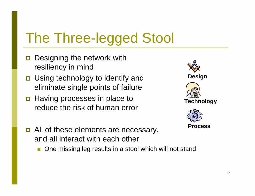
Design
Technology
ProcessProcess
The Three-legged Stool Designing the network with
resiliency in mind Using technology to identify and
eliminate single points of failure Having processes in place to
reduce the risk of human error
All of these elements are necessary, and all interact with each other One missing leg results in a stool which will not stand
6
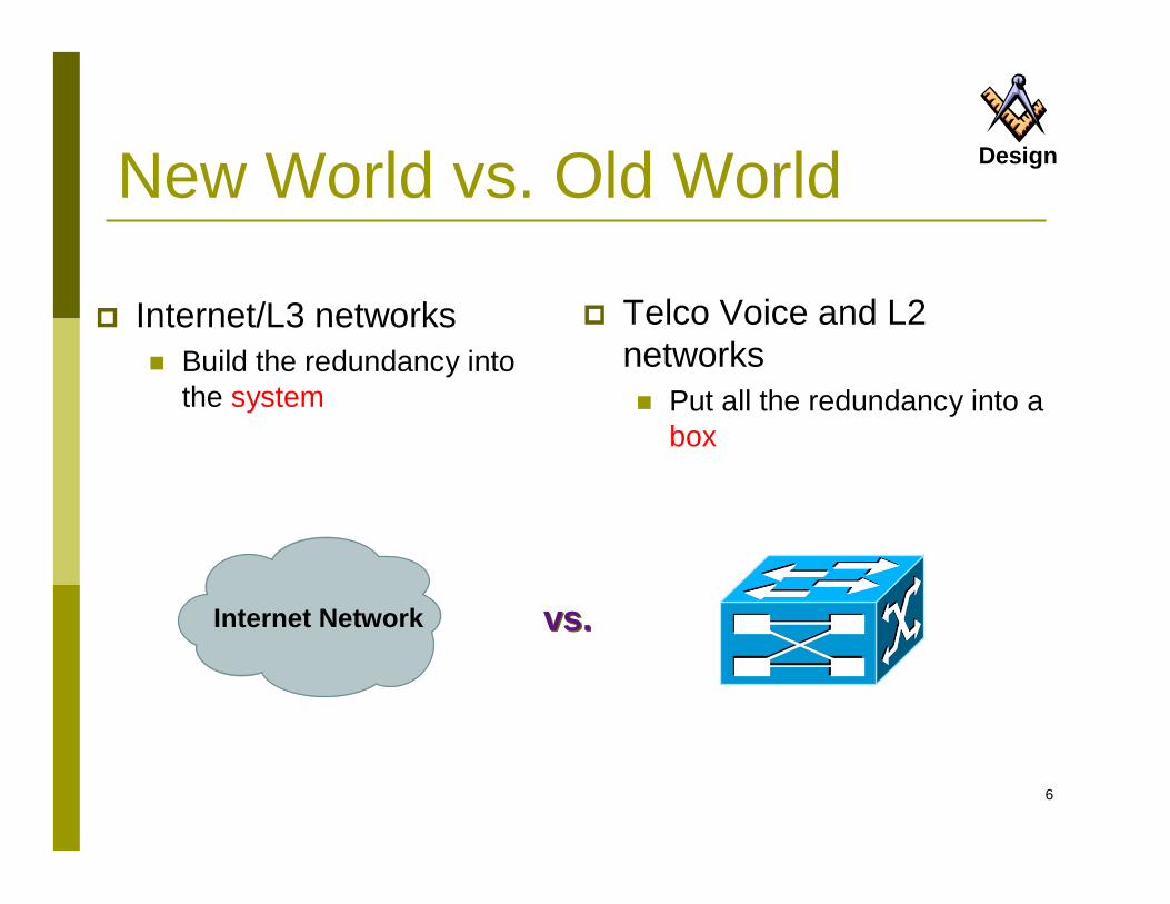
New World vs. Old World
Internet/L3 networks Build the redundancy into
the system
Telco Voice and L2 networks Put all the redundancy into a
box
Internet Network vs.vs.
Design
7
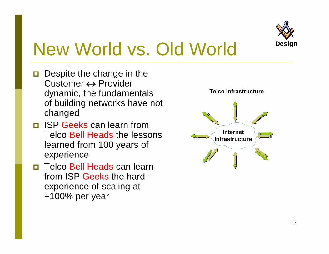
New World vs. Old World Despite the change in the
Customer Provider dynamic, the fundamentals of building networks have not changed
ISP Geeks can learn from Telco Bell Heads the lessons learned from 100 years of experience
Telco Bell Heads can learn from ISP Geeks the hard experience of scaling at +100% per year
Telco Infrastructure
InternetInfrastructure
Design
8
Joel Snyder – Network World Test Alliance 1/10/2000“Reliability: Something you build, not buy”
How Do We Get There?
“In the Internet era, reliability is becoming something you have to build, not something you buy. That is hard work, and it requires intelligence, skills and budget. Reliability is not part of the basic package.”
Design
9
Redundant Network Design
Concepts and Techniques
10
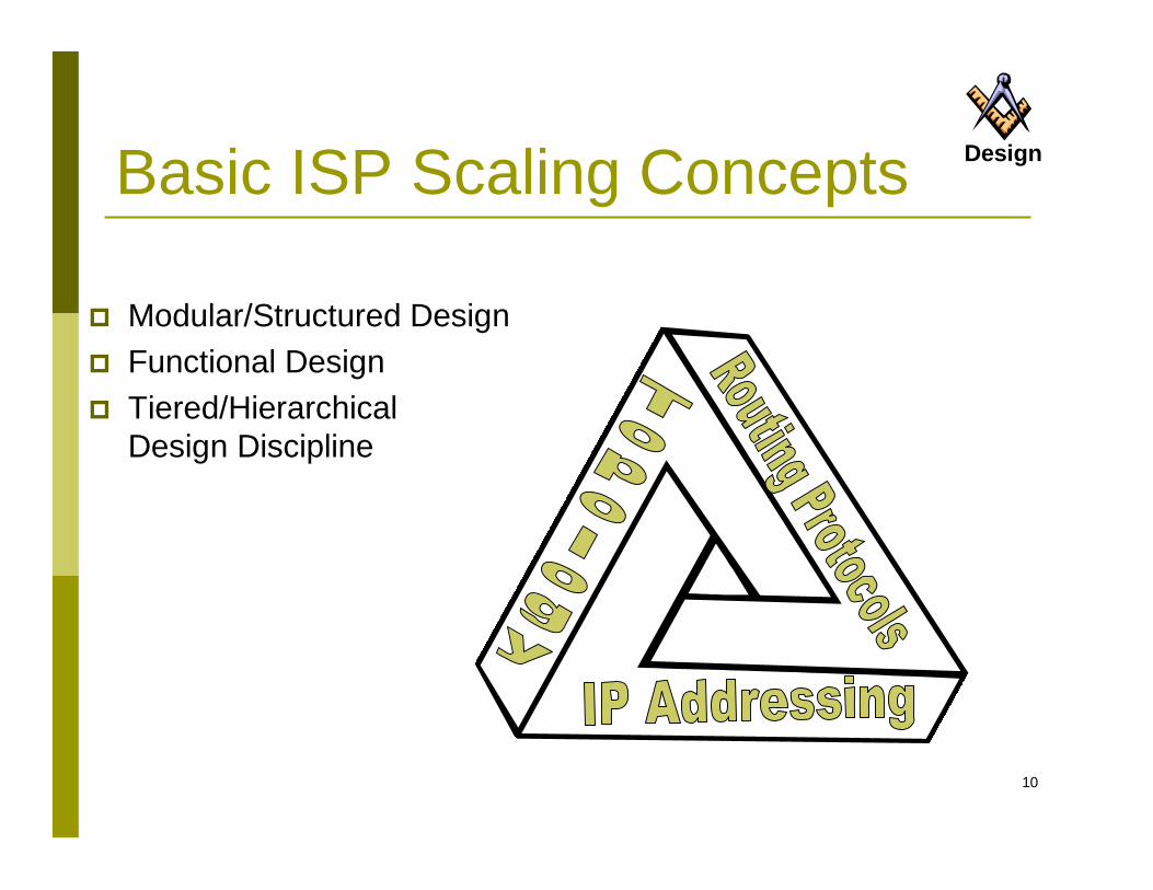
Basic ISP Scaling Concepts
Modular/Structured Design Functional Design Tiered/Hierarchical
Design Discipline
Design
11
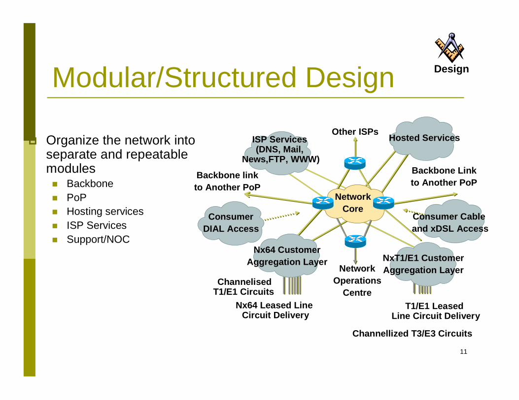
Modular/Structured Design
Organize the network into separate and repeatable modules Backbone PoP Hosting services ISP Services Support/NOC
Backbone Linkto Another PoP
Backbone linkto Another PoP
Nx64 Leased Line Circuit Delivery
ChannelisedT1/E1 Circuits
T1/E1 Leased Line Circuit Delivery
Channellized T3/E3 Circuits
NetworkOperations
Centre
Other ISPs
NetworkCore
Nx64 CustomerAggregation Layer
ConsumerDIAL Access
ISP Services(DNS, Mail,
News,FTP, WWW)
NxT1/E1 CustomerAggregation Layer
Consumer Cableand xDSL Access
Hosted Services
Design
12
Modular/Structured Design Modularity makes it easy to scale
a network Design smaller units of the network that are then
plugged into each other Each module can be built for a specific function in the
network Upgrade paths are built around the modules, not the
entire network
Design
13
DesignFunctional Design One Box cannot do everything
(no matter how hard people have tried in the past) Each router/switch in a network has a well-defined set of
functions The various boxes interact with each other Equipment can be selected and functionally placed in a
network around its strengths ISP Networks are a systems approach to design
Functions interlink and interact to form a network solution.
14Access Layer
DistributionLayer
Other Regions
Other Regions
Other Regions
Core
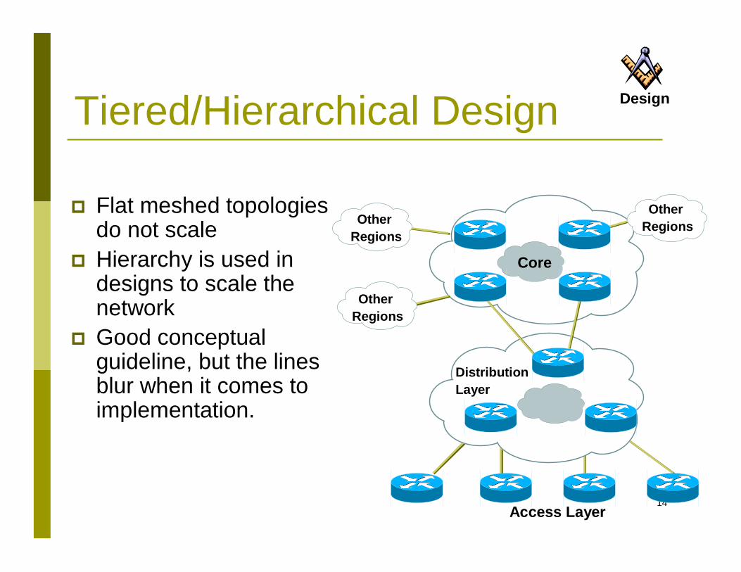
Tiered/Hierarchical Design
Flat meshed topologies do not scale
Hierarchy is used in designs to scale the network
Good conceptual guideline, but the lines blur when it comes to implementation.
Design
15
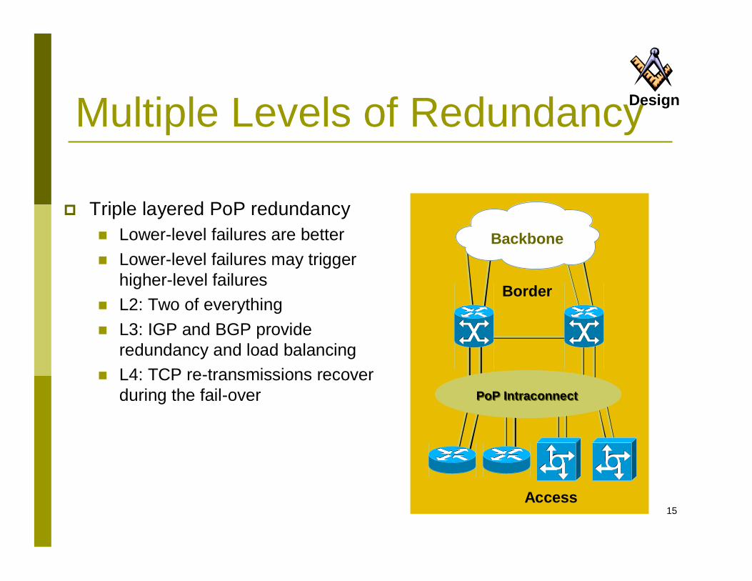
Multiple Levels of Redundancy
Triple layered PoP redundancy Lower-level failures are better Lower-level failures may trigger
higher-level failures L2: Two of everything L3: IGP and BGP provide
redundancy and load balancing L4: TCP re-transmissions recover
during the fail-over Intra-POP Interconnect
Border
Backbone
Access
PoP IntraconnectPoP Intraconnect
Design
16
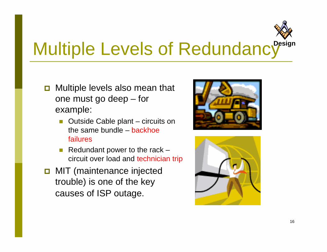
Multiple Levels of Redundancy
Multiple levels also mean that one must go deep – for example: Outside Cable plant – circuits on
the same bundle – backhoe failures
Redundant power to the rack –circuit over load and technician trip
MIT (maintenance injected trouble) is one of the key causes of ISP outage.
Design
17
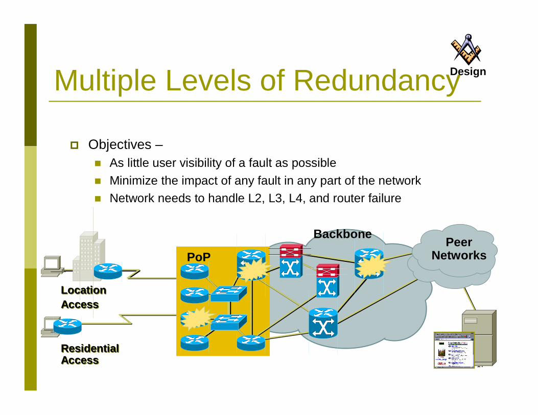
Multiple Levels of Redundancy
PoP
Backbone PeerNetworks
Residential AccessResidential Access
LocationAccessLocationAccess
Objectives – As little user visibility of a fault as possible Minimize the impact of any fault in any part of the network Network needs to handle L2, L3, L4, and router failure
Design
18
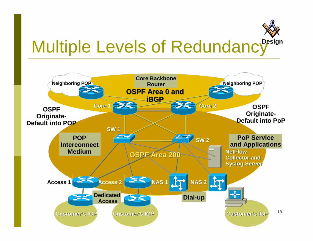
Multiple Levels of Redundancy
Customer’s IGPCustomer’s IGP Customer’s IGPCustomer’s IGP Customer’s IGPCustomer’s IGP
Access 1 Access 2Access 2 NAS 1NAS 1 NAS 2NAS 2
NetFlow Collector and Syslog Server
NetFlow Collector and Syslog Server
SW 1SW 1
OSPF Area 0 and iBGP
OSPF Area 0 and iBGP
Neighboring POP Neighboring POP
Core 1Core 1 Core 2Core 2
SW 2SW 2
OSPF Area 200OSPF Area 200
OSPFOriginate-
Default into POP
OSPFOriginate-
Default into PoP
Dial-upDedicatedAccess
POPInterconnect
Medium
PoP Service and Applications
Core Backbone Router
Design
19
Redundant Network DesignThe Basics
20
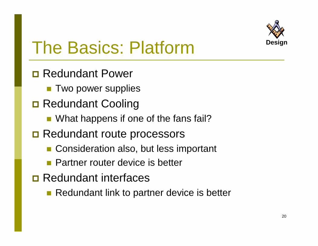
DesignThe Basics: Platform Redundant Power
Two power supplies Redundant Cooling
What happens if one of the fans fail? Redundant route processors
Consideration also, but less important Partner router device is better
Redundant interfaces Redundant link to partner device is better
21
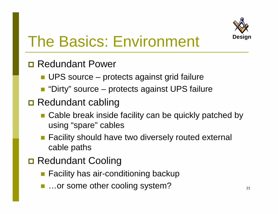
DesignThe Basics: Environment Redundant Power
UPS source – protects against grid failure “Dirty” source – protects against UPS failure
Redundant cabling Cable break inside facility can be quickly patched by
using “spare” cables Facility should have two diversely routed external
cable paths Redundant Cooling
Facility has air-conditioning backup …or some other cooling system?
22
Redundant Network Design
Within the DataCentre
23
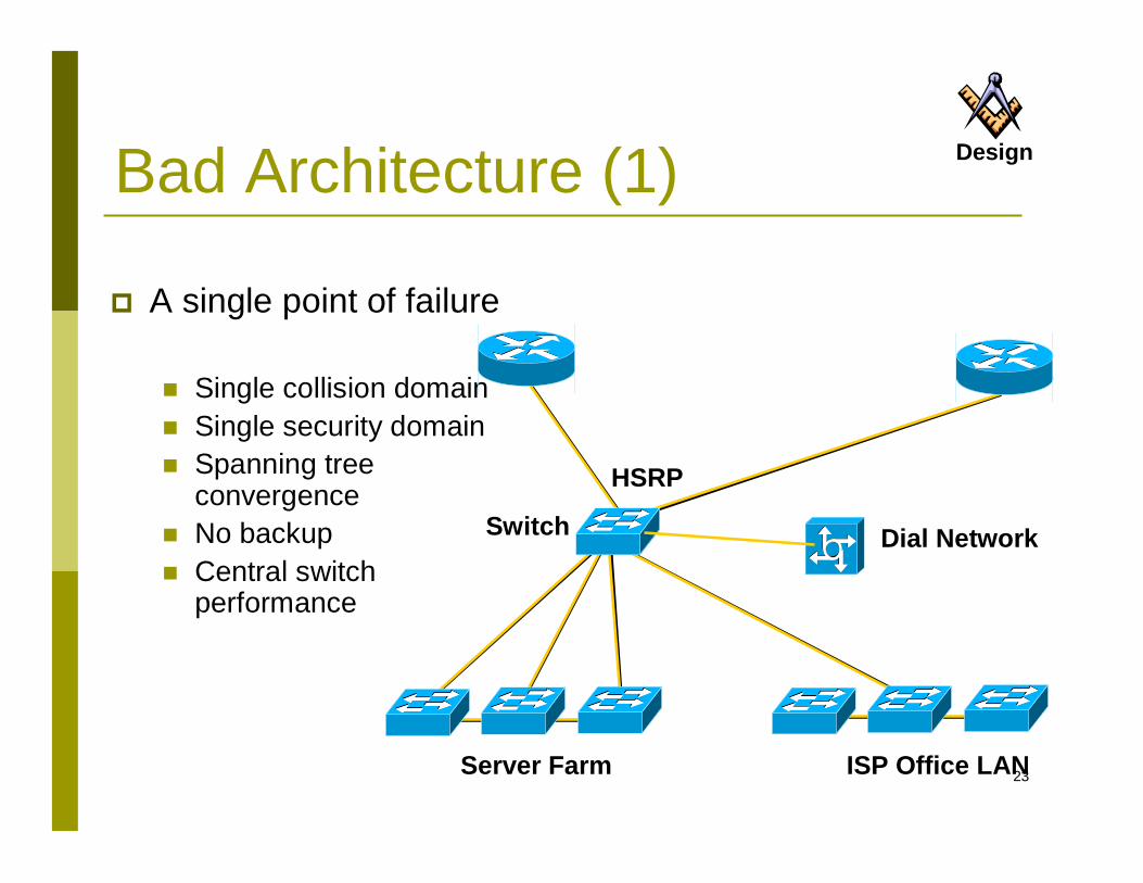
Bad Architecture (1)
A single point of failure
Single collision domain Single security domain Spanning tree
convergence No backup Central switch
performance
Server Farm ISP Office LAN
HSRP
Switch
Design
Dial Network
24
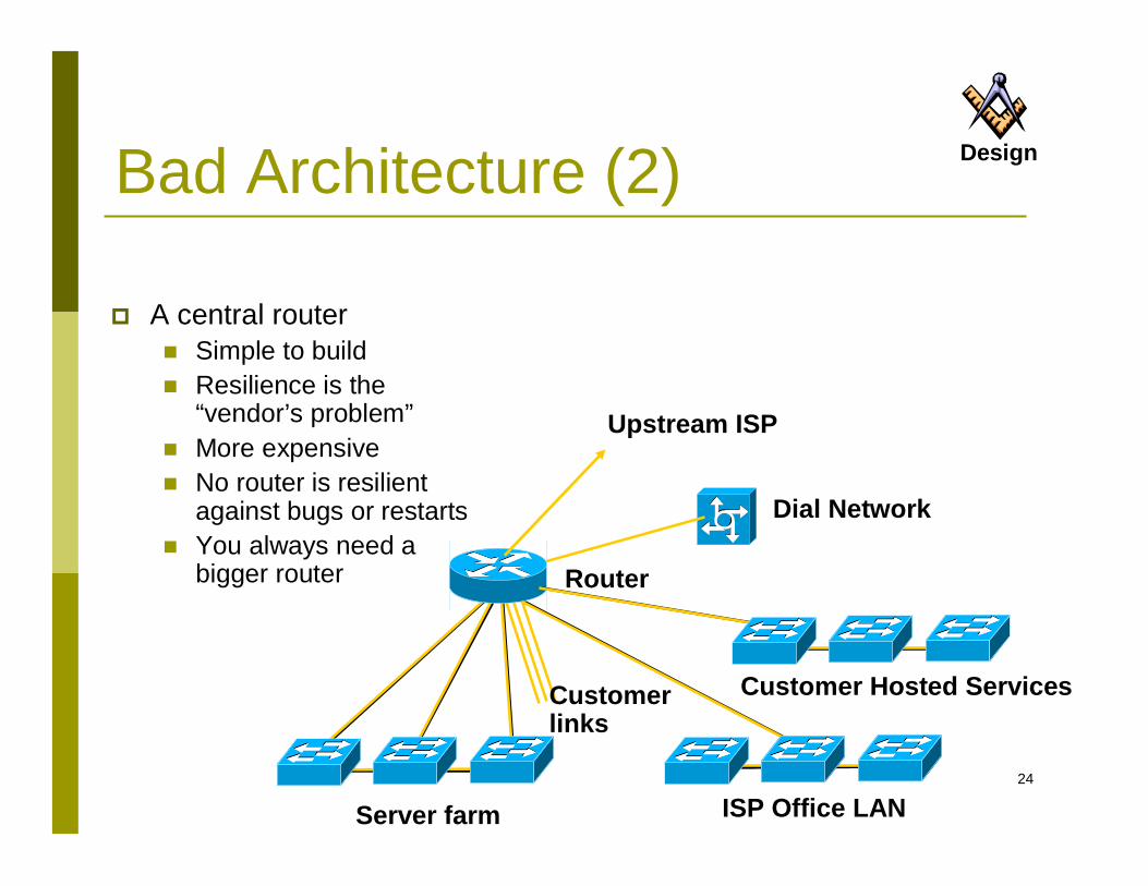
Bad Architecture (2)
A central router Simple to build Resilience is the
“vendor’s problem” More expensive No router is resilient
against bugs or restarts You always need a
bigger router
Design
Dial Network
Server farm
Customer Hosted Services
Router
ISP Office LAN
Upstream ISP
Customer links
25
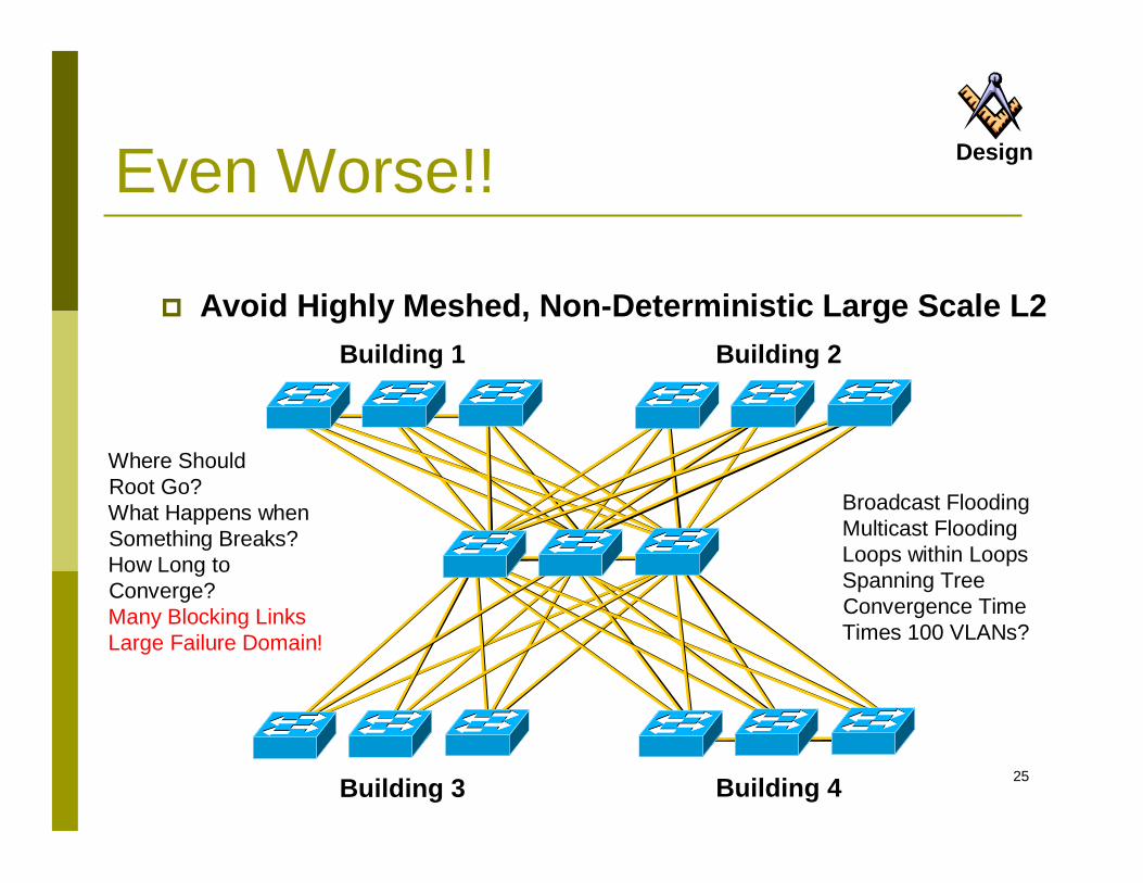
Even Worse!!
Avoid Highly Meshed, Non-Deterministic Large Scale L2
Building 3 Building 4
Building 1 Building 2
Where Should Root Go?What Happens when Something Breaks?How Long to Converge?Many Blocking LinksLarge Failure Domain!
Broadcast FloodingMulticast FloodingLoops within LoopsSpanning Tree Convergence TimeTimes 100 VLANs?
Design
26
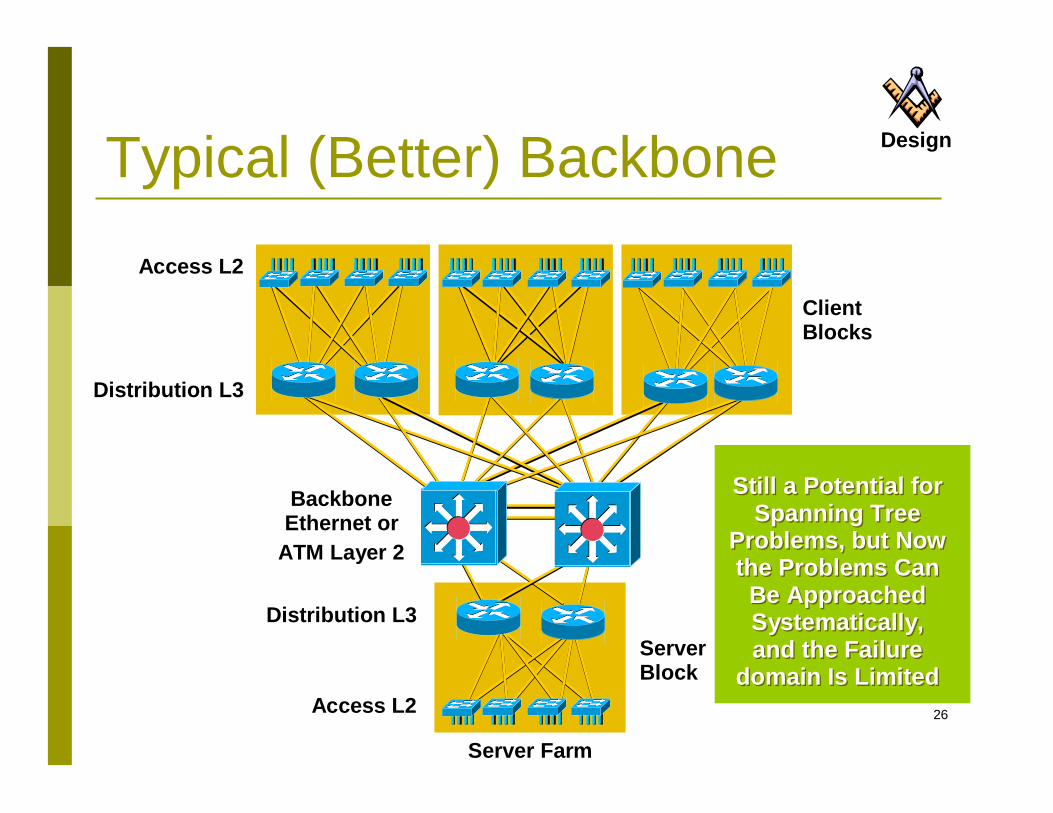
ClientBlocks
Distribution L3
Access L2
ServerBlock
Server Farm
Distribution L3
Access L2
BackboneEthernet or
ATM Layer 2
Still a Potential for Spanning Tree
Problems, but Now the Problems Can
Be Approached Systematically, and the Failure
domain Is Limited
Still a Potential for Spanning Tree
Problems, but Now the Problems Can
Be Approached Systematically, and the Failure
domain Is Limited
Typical (Better) Backbone Design
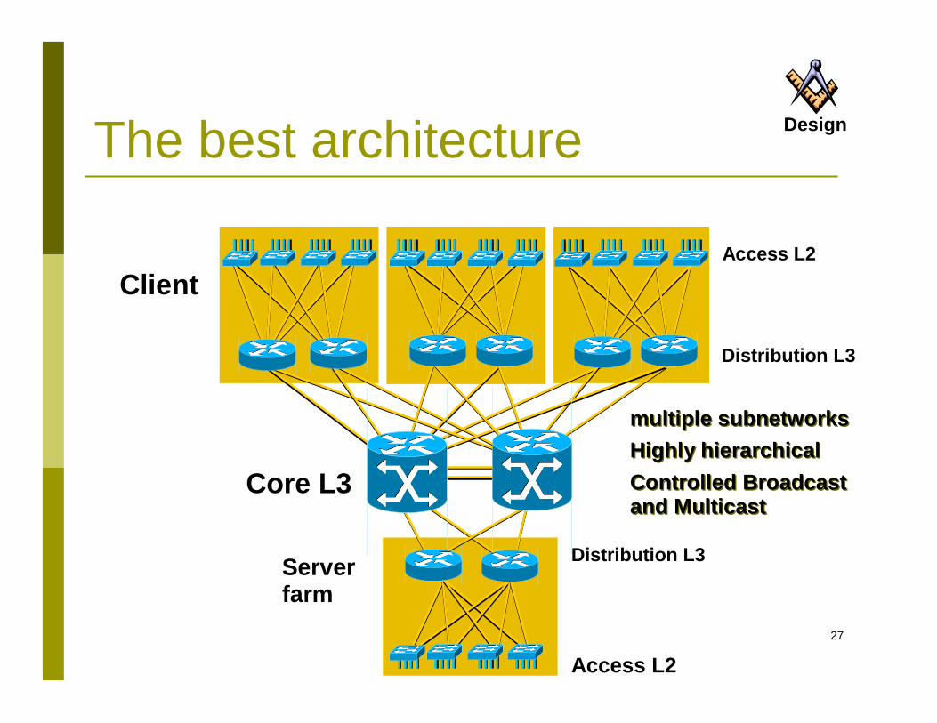
27
The best architecture
Distribution L3
Access L2
Core L3
Server farm
Access L2
multiple subnetworksHighly hierarchicalControlled Broadcast and Multicast
multiple subnetworksHighly hierarchicalControlled Broadcast and Multicast
Client
Distribution L3
Design
28
TechnologyBenefits of Layer 3 backbone Multicast PIM routing control Load balancing No blocked links Fast convergence OSPF/ISIS/EIGRP Greater scalability overall Router peering reduced

29
Redundant Network Design
Server Availability
30
11
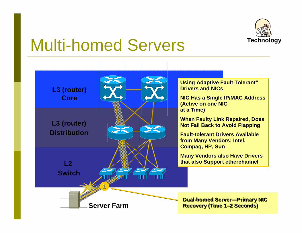
Using Adaptive Fault Tolerant”Drivers and NICs
NIC Has a Single IP/MAC Address (Active on one NIC at a Time)
When Faulty Link Repaired, Does Not Fail Back to Avoid Flapping
Fault-tolerant Drivers Available from Many Vendors: Intel, Compaq, HP, Sun
Many Vendors also Have Drivers that also Support etherchannel
Server Farm
Multi-homed Servers
Dual-homed Server—Primary NIC Recovery (Time 1–2 Seconds)Dual-homed Server—Primary NIC Recovery (Time 1–2 Seconds)
L3 (router)Core
L3 (router)Distribution
L2 Switch
Technology
31
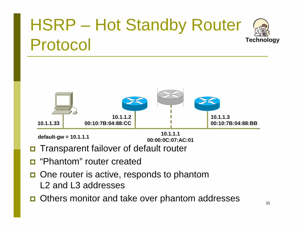
10.1.1.300:10:7B:04:88:BB10.1.1.33
10.1.1.100:00:0C:07:AC:01
10.1.1.200:10:7B:04:88:CC
default-gw = 10.1.1.1
Technology
HSRP – Hot Standby Router Protocol
Transparent failover of default router “Phantom” router created One router is active, responds to phantom
L2 and L3 addresses Others monitor and take over phantom addresses
32
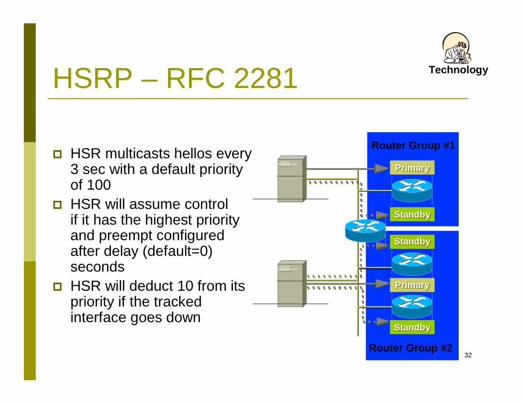
Router Group #1
Router Group #2
StandbyStandby
StandbyStandby
StandbyStandby
PrimaryPrimary
PrimaryPrimary
HSRP – RFC 2281
HSR multicasts hellos every 3 sec with a default priority of 100
HSR will assume control if it has the highest priority and preempt configured after delay (default=0) seconds
HSR will deduct 10 from its priority if the tracked interface goes down
Technology
33
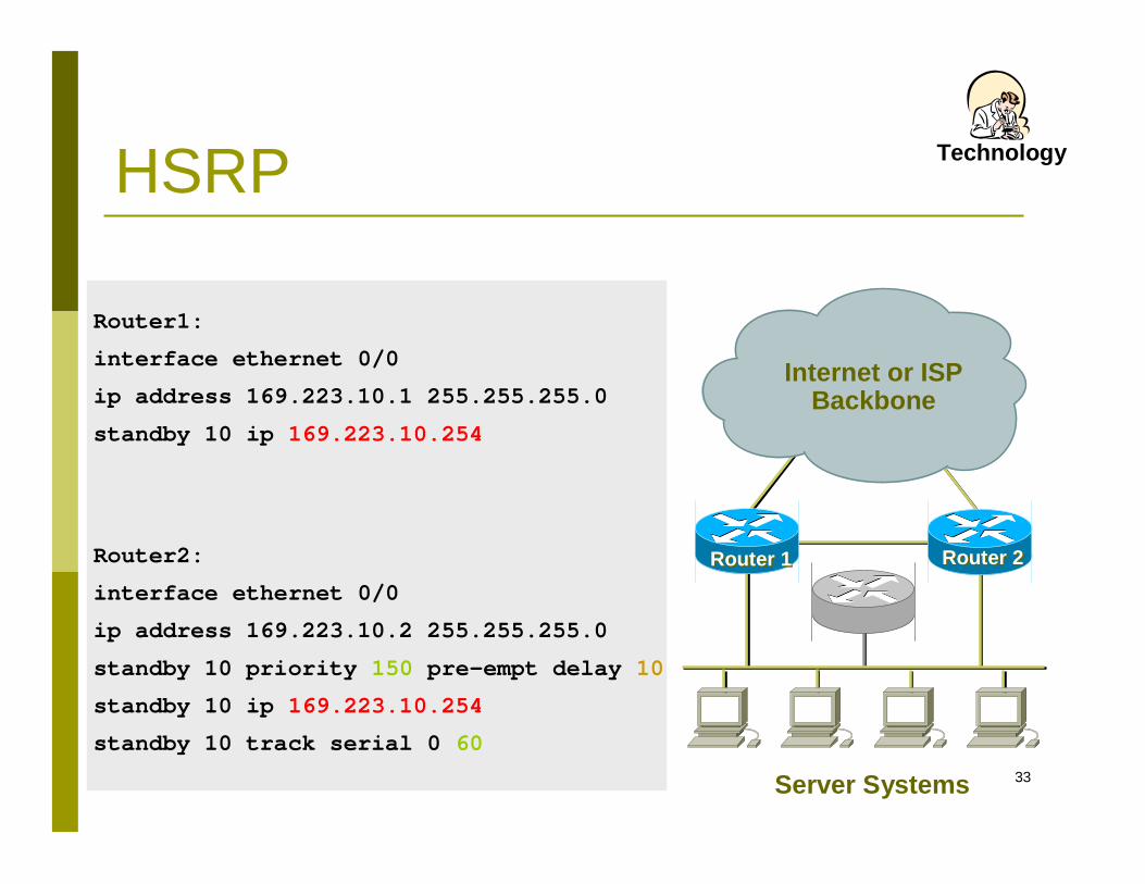
Router2:
interface ethernet 0/0
ip address 169.223.10.2 255.255.255.0
standby 10 priority 150 pre-empt delay 10
standby 10 ip 169.223.10.254
standby 10 track serial 0 60
HSRP
Internet or ISPBackbone
Server Systems
Router 1Router 1 Router 2Router 2
Router1:
interface ethernet 0/0
ip address 169.223.10.1 255.255.255.0
standby 10 ip 169.223.10.254
Technology
34
Redundant Network Design
WAN Availability
35
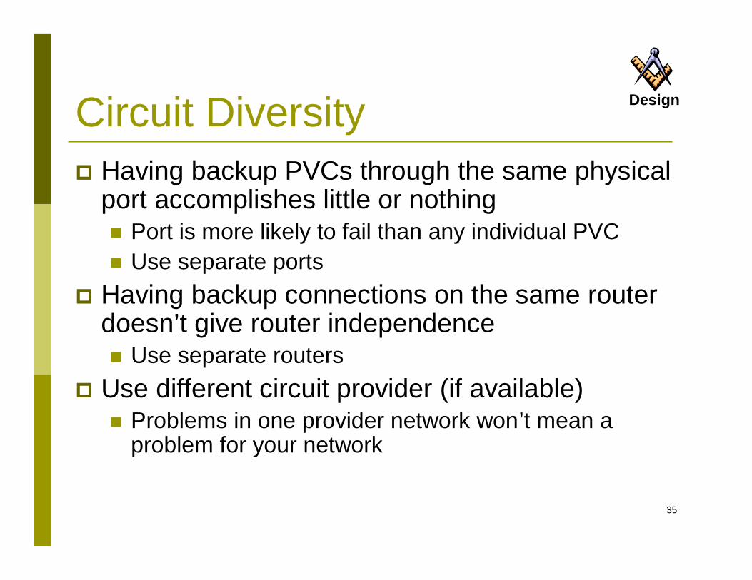
DesignCircuit Diversity Having backup PVCs through the same physical
port accomplishes little or nothing Port is more likely to fail than any individual PVC Use separate ports
Having backup connections on the same router doesn’t give router independence Use separate routers
Use different circuit provider (if available) Problems in one provider network won’t mean a
problem for your network
36
DesignCircuit Diversity Ensure that facility has diverse circuit paths to
telco provider or providers Make sure your backup path terminates into
separate equipment at the service provider Make sure that your lines are not trunked into
the same paths as they traverse the network Try and write this into your Service Level
Agreement with providers
37
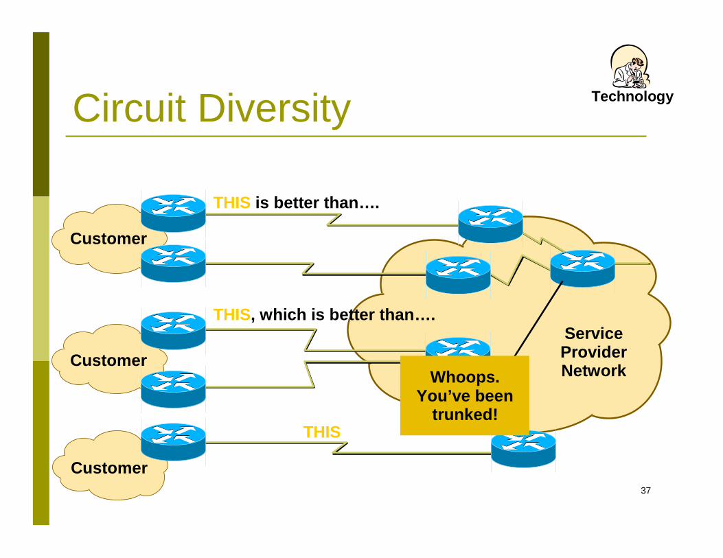
Service ProviderNetwork
Circuit Diversity
Customer
THIS is better than….
Technology
Customer
THIS, which is better than….
Customer
THIS
Whoops. You’ve been
trunked!
38
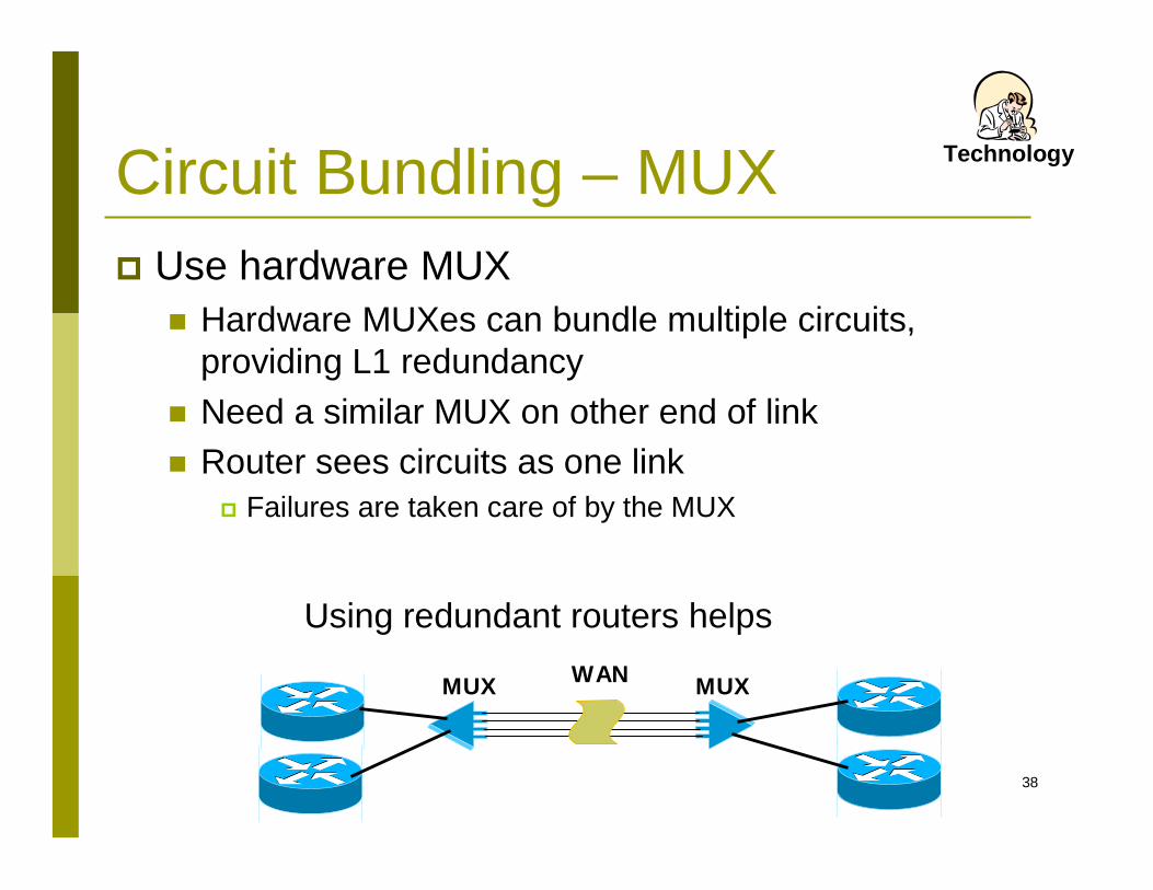
Circuit Bundling – MUX Use hardware MUX
Hardware MUXes can bundle multiple circuits, providing L1 redundancy
Need a similar MUX on other end of link Router sees circuits as one link
Failures are taken care of by the MUX
MUX MUXWAN
Using redundant routers helps
Technology
39
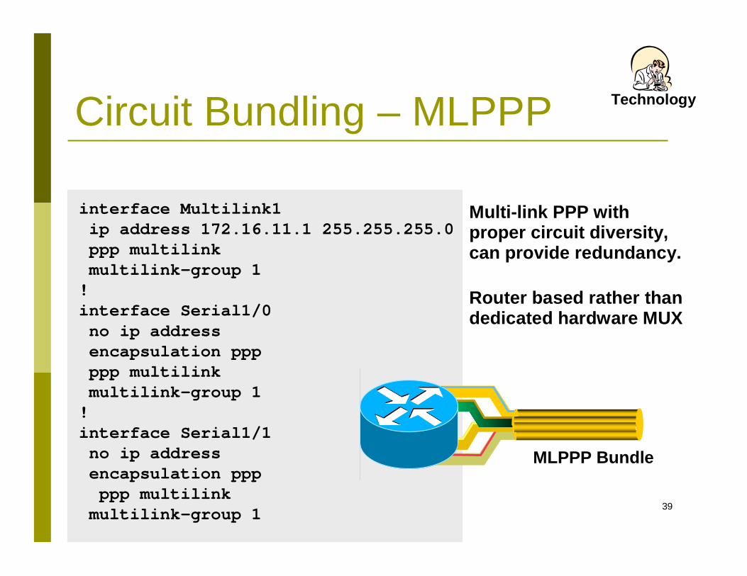
interface Multilink1ip address 172.16.11.1 255.255.255.0ppp multilinkmultilink-group 1!interface Serial1/0no ip addressencapsulation pppppp multilinkmultilink-group 1!interface Serial1/1no ip addressencapsulation pppppp multilinkmultilink-group 1
MLPPP Bundle
Multi-link PPP with proper circuit diversity, can provide redundancy.
Router based rather than dedicated hardware MUX
Circuit Bundling – MLPPP Technology
40
DesignLoad Sharing Load sharing occurs when a router has two
(or more) equal cost paths to the same destination EIGRP also allows unequal-cost load sharing Load sharing can be on a per-packet or
per-destination basis (default: per-destination) Load sharing can be a powerful redundancy technique,
since it provides an alternate path should a router/path fail
41
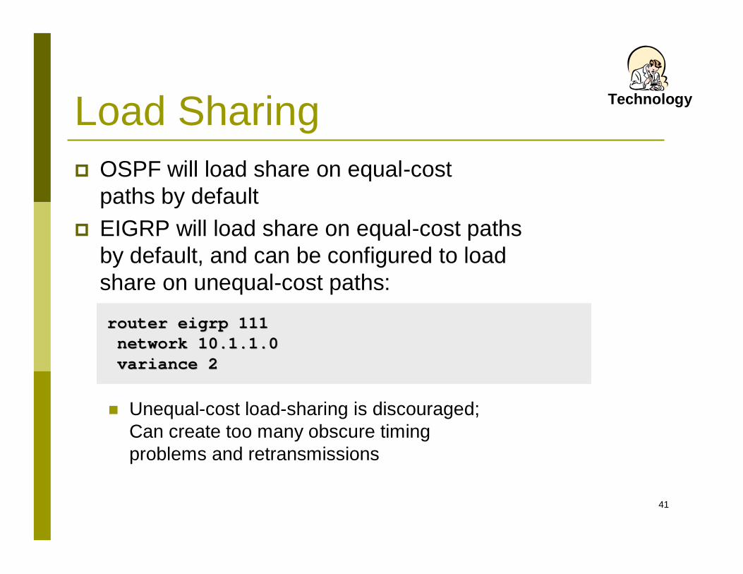
router router eigrpeigrp 111111network 10.1.1.0network 10.1.1.0variance 2 variance 2
TechnologyLoad Sharing OSPF will load share on equal-cost
paths by default EIGRP will load share on equal-cost paths
by default, and can be configured to load share on unequal-cost paths:
Unequal-cost load-sharing is discouraged;Can create too many obscure timing problems and retransmissions
42
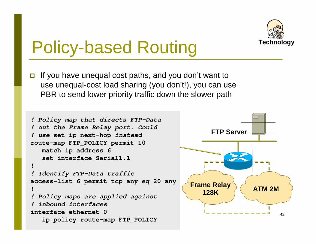
Frame Relay128K ATM 2M
FTP Server
Policy-based Routing If you have unequal cost paths, and you don’t want to
use unequal-cost load sharing (you don’t!), you can use PBR to send lower priority traffic down the slower path
! Policy map that directs FTP-Data! out the Frame Relay port. Could ! use set ip next-hop insteadroute-map FTP_POLICY permit 10
match ip address 6 set interface Serial1.1
!! Identify FTP-Data trafficaccess-list 6 permit tcp any eq 20 any!! Policy maps are applied against! inbound interfacesinterface ethernet 0
ip policy route-map FTP_POLICY
Technology
43
Convergence
The convergence time of the routing protocol chosen will affect overall availability of your WAN
Main area to examine is L2 design impact on L3 efficiency
Design
44
BFD BFD - Bidirectional Forwarding Detection
Used to QUICKLY detect local/remote link failure Between 50ms and 300ms Signals upper-layer routing protocols to converge
OSPF BGP EIGRP IS-IS HSRP Static routes
Especially useful on Ethernet links - where remote failure detection may not be easily identifiable.
45
IETF Graceful Restart Graceful Restart
Allows a router’s control plane to restart without signaling a failure of the routing protocol to its neighbors.
Forwarding continues while switchover to the backup control plane is initiated.
Supports several routing protocols OSPF (OSPFv2 & OSPFv3) BGP IS-IS RIP & RIPng PIM-SM LDP RSVP
46
NSR NSR - Non-Stop Routing
A little similar to IETF Graceful Restart, but… Rather than depend on neighbors to maintain routing
and forwarding state during control plane switchovers…
The router maintains 2 identical copies of the routing state on both control planes.
Failure of the primary control plane causes forwarding to use the routing table on the backup control plane.
Switchover and recovery is independent of neighbor routers, unlike IETF Graceful Restart.
47
VRRP VRRP - Virtual Router Redundancy Protocol
Similar to HSRP or GLBP But is an open standard Can be used between multiple router vendors, e.g.,
between Cisco and Juniper
48
ISSU ISSU - In-Service Software Upgrade
Implementation may be unique to each router vendor Basic premise is to modularly upgrade software
features and/or components without having to reboot the router
Support from vendors still growing, and not supported on all platforms
Initial support is on high-end platforms that support either modular or microkernel-based operating systems
49
MPLS-TE MPLS Traffic Engineering
Allows for equal-cost load balancing Allows for unequal cost load balancing
Makes room for MPLS FRR (Fast Reroute) FRR provides SONET-like recovery of 50ms Ideal for so-called “converged” networks carrying
voice, video and data
50
Control Plane QoS QoS - Quality of Service (Control Plane)
Useful for control plane protection Ensures network congestion do not cause network
control traffic drops Keeps routing protocols up and running Guarantees network stability Cisco features:
CoPP (Control Plane Policing) CPPr (Control Plane Protection)
51
Factors Determining Protocol Convergence Network size Hop count limitations Peering arrangements (edge, core) Speed of change detection Propagation of change information Network design: hierarchy, summarization,
redundancy
Design
52
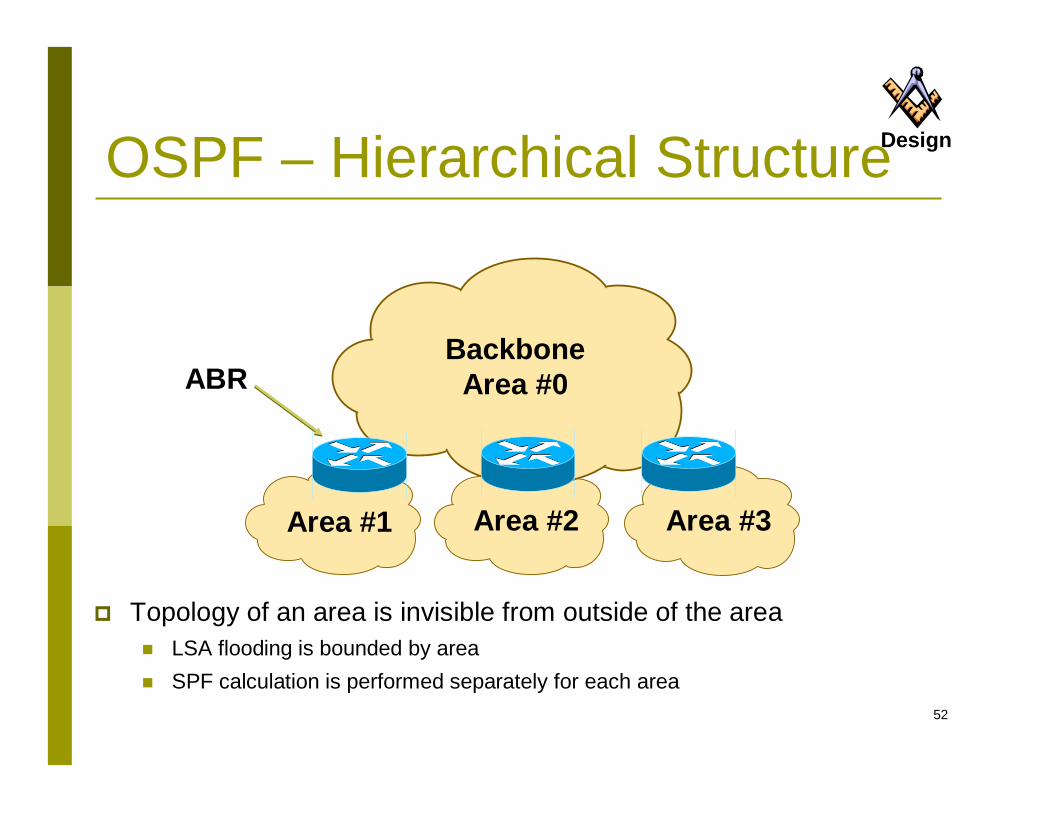
BackboneArea #0
Area #1 Area #2 Area #3
ABR
OSPF – Hierarchical Structure
Topology of an area is invisible from outside of the area LSA flooding is bounded by area SPF calculation is performed separately for each area
Design
53
Factors AssistingProtocol Convergence Keep number of routing devices in each topology area small (15 –
20 or so) Reduces convergence time required
Avoid complex meshing between devices in an area Two links are usually all that are necessary
Keep prefix count in interior routing protocols small Large numbers means longer time to compute shortest path
Use vendor defaults for routing protocol unless you understand the impact of “twiddling the knobs” Knobs are there to improve performance in certain conditions only
Design
54
Redundant Network Design
Internet Availability
55
PoP Design One router cannot do it all Redundancy redundancy redundancy Most successful ISPs build two of everything Two smaller devices in place of one larger
device: Two routers for one function Two switches for one function Two links for one function
Design
56
PoP Design Two of everything does not mean complexity Avoid complex highly meshed network designs
Hard to run Hard to debug Hard to scale Usually demonstrate poor performance
Design
57
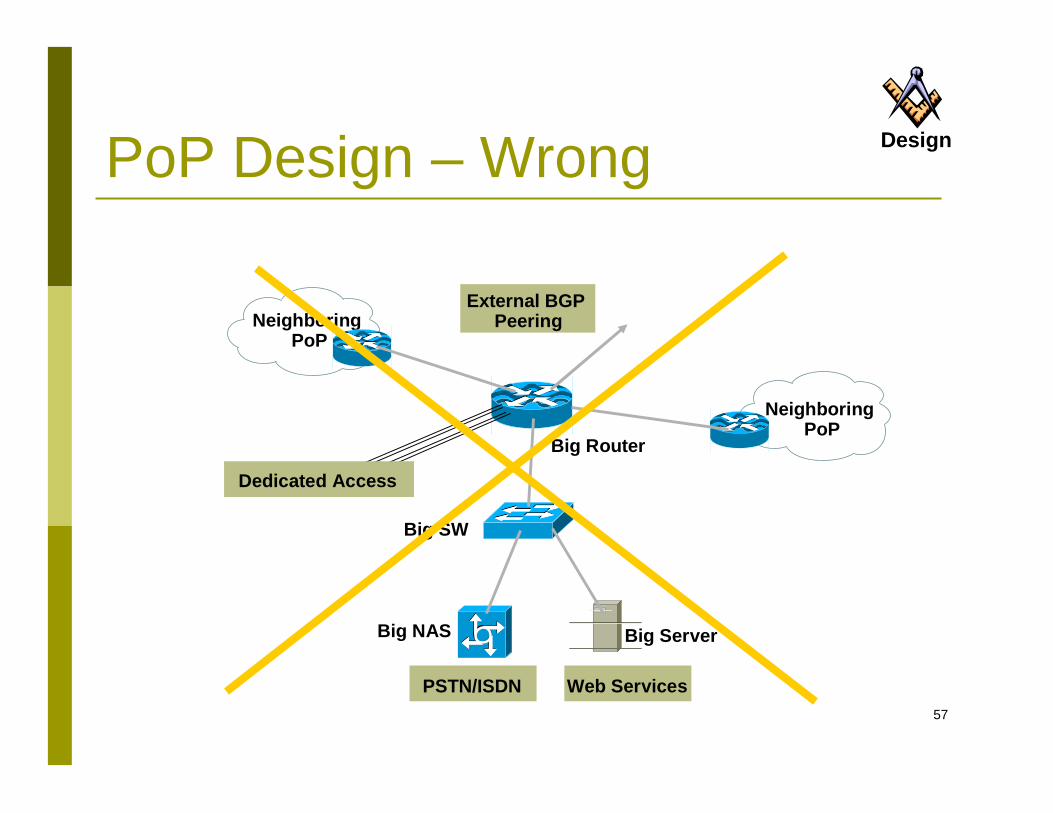
PoP Design – Wrong
NeighboringPoP
PSTN/ISDN
Big SW
Big NAS
External BGP Peering
NeighboringPoP
Design
Dedicated Access
Big Router
Big Server
Web Services
58
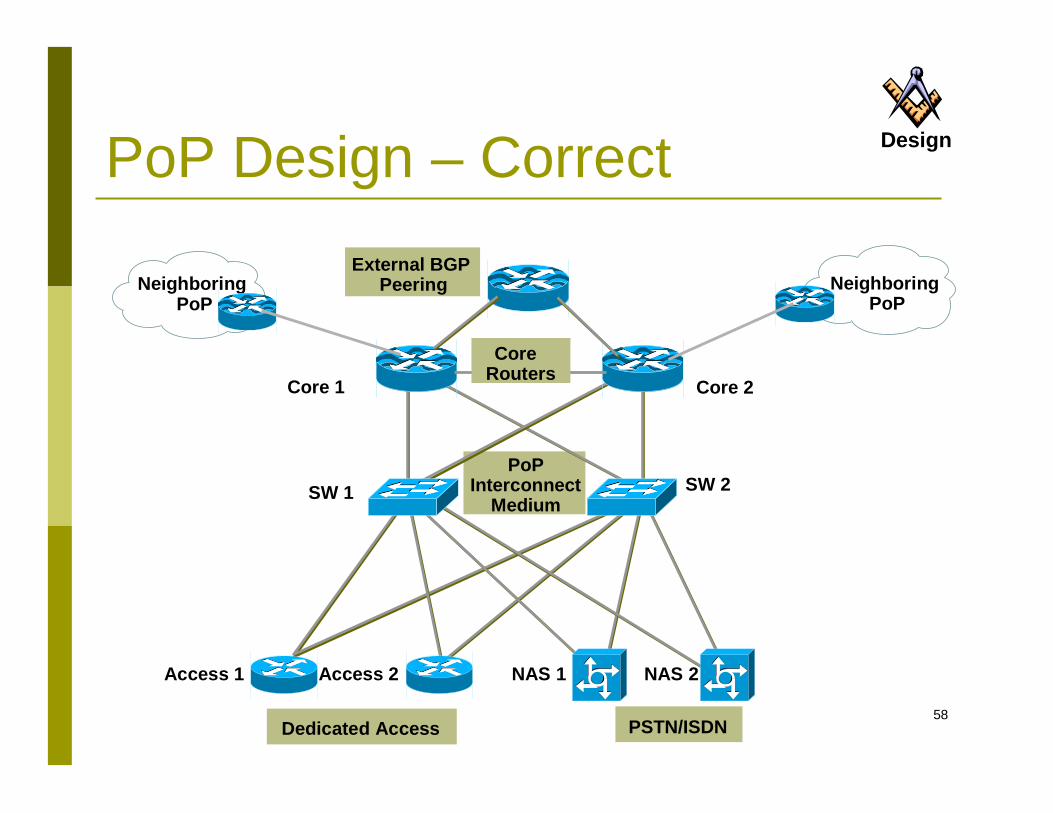
PoP Design – Correct
PoPInterconnect
Medium
NeighboringPoP
Dedicated Access PSTN/ISDN
Core 1 Core 2
SW 1 SW 2
Access 1 Access 2 NAS 1 NAS 2
External BGP Peering Neighboring
PoP
Design
Core Routers
59
Hubs vs. Switches Hubs
These are obsolete Switches cost little more
Traffic on hub is visible on all ports It’s really a replacement for coax ethernet Security!?
Performance is very low 10Mbps shared between all devices on LAN High traffic from one device impacts all the others
Usually non-existent management
Technology
60
TechnologyHubs vs. Switches Switches
Each port is masked from the other High performance
10/100/1000Mbps per port Traffic load on one port does not impact other ports
10/100/1000 switches are commonplace and cheap Choose non-blocking switches in core
Packet doesn’t have to wait for switch Management capability (SNMP via IP, CLI) Redundant power supplies are useful to have
61
Beware Static IP Dial Problems
Does NOT scale Customer /32 routes in IGP – IGP won’t scale More customers, slower IGP convergence Support becomes expensive
Solutions Route “Static Dial” customers to same RAS or RAS
group behind distribution router Use contiguous address block Make it very expensive – it costs you money to
implement and support
Design
62
Redundant Network DesignOperations!
63
Network Operations Centre NOC is necessary for a small ISP
It may be just a PC called NOC, on UPS, in equipment room.
Provides last resort access to the network Captures log information from the network Has remote access from outside
Dialup, SSH,… Train staff to operate it Scale up the PC and support as the business grows
ProcessProcess
64
Operations A NOC is essential for all ISPs Operational Procedures are necessary
Monitor fixed circuits, access devices, servers If something fails, someone has to be told
Escalation path is necessary Ignoring a problem won’t help fixing it. Decide on time-to-fix, escalate up reporting chain until
someone can fix it
ProcessProcess
65
Operations Modifications to network
A well designed network only runs as well as those who operate it
Decide and publish maintenance schedules And then STICK TO THEM Don’t make changes outside the maintenance period,
no matter how trivial they may appear
ProcessProcess
66
Design
Technology
ProcessProcess
In Summary Implementing a highly resilient
IP network requires a combination of the proper process, design and technology
“and now abideth design, technology and process, these three; but the greatest of these is process”
And don’t forget to KISS! Keep It Simple & Stupid!
67
Acknowledgements The materials and Illustrations are based on the
Cisco Networkers’ Presentations Philip Smith of Cisco Systems Brian Longwe of Inhand .Ke
Related Documents