Residual mass and flow regimes for the immiscible liquid–liquid displacement in a plane channel Jackson F. Freitas a , Edson J. Soares a,⇑ , Roney L. Thompson b a LFTC, Department of Mechanical Engineering, Universidade Federal do Espirito Santo, Avenida Fernando Ferrari, 514, Goiabeiras 29075-910, ES, Brazil b LFTC, LMTA-PGMEC, Department of Mechanical Engineering, Universidade Federal Fluminense, Rua Passo da Patria 156, 24210-240 Niteroi, RJ, Brazil article info Article history: Received 10 May 2010 Received in revised form 21 February 2011 Accepted 3 March 2011 Available online 9 March 2011 Keywords: Plane channel Liquid–liquid displacement Finite element method Residual mass abstract The motion of two immiscible liquids in a plane channel is analyzed for the case in which the flow con- ditions and the interactions between the liquids and the solid surface maintain the displaced fluid attached to the wall. The Galerkin Finite Element Method is used to compute the velocity field and the configuration of the interface between the two fluids. We compare the residual mass fraction left on the wall with its two counterparts in capillary tubes, namely residual mass fraction and dimensionless layer thickness of the displaced fluid. The main result of this comparison was that although there is a qualitative similarity concerning the layer thickness between the two cases, the residual fraction of mass presented an important difference, showing that when the aspect ratio of the capillary passage is large there is an increase in the displacement efficiency. The thickness of the displaced liquid film attached to the channel walls is a function of the capillary number (Ca) and the viscosity ratio (N l ). A map of streamlines in the Cartesian space (Ca, N l ) with the different flow regimes of the problem is presented. We also showed that we can adapt the available analytical results obtained for gas-displacement in cap- illary tubes to the plane channel case, for low values of Ca. Ó 2011 Elsevier Ltd. All rights reserved. 1. Introduction We investigate in the present work the liquid–liquid displace- ment in a plane channel. Examples of applications where this kind of problem is important are the oil recovery from porous media and the cementation of oil wells. The liquid film of the displaced material that remains attached to the walls plays a significant role in the efficiency of these operations. As a consequence of the small length scale, the capillary forces have a fundamental importance on the physics of the phenomenon. The complete 3-D liquid–liquid displacement analysis of oil recovery in porous media depends on the shape of the cross sec- tional area of the pore. When the aspect ratio of this area is around unity the tube is a reasonable approximation. However, when the aspect ratio of the cross sectional area of these internal passages is large, a plane 2-D geometry is preferred to represent the geomet- rical features of the pore. There are two different outputs of interest in the fluid–fluid dis- placement problem depicted in Fig. 1. One, is the fraction of mass of Phase 2 attached to the wall, m, calculated as m ¼ Area occupied by Phase 2 at Region IV Area occupied by Phase 2 at Region I : ð1Þ The other output is the dimensionless thickness of the same layer, h / , which can be defined as h ¼ Layer thickness of Phase 2 attached to the wall Half of the distance between the plates : ð2Þ For a 2-D Cartesian case, a plane channel, it happens that these two entities lead to the same quantity. This coincidence does not occur in a tube, where m > h / . In fact one can find, in the literature of dis- placement in tubes, the output result emphasizing the first, e.g. (Taylor, 1961), or the second, e.g. (Westborg and Hassager, 1989), quantity. It should be mentioned that, depending on the problem considered, one result or the other is of particular interest. For example, in the oil recovery process, the fraction of residual mass is more adequate to measure a displacing efficiency, while in the cementing of a oil well or in a coating process, the layer thickness is the quantity to be controlled. Concerning the liquid–liquid displacement in a capillary space, it seems that the first investigation was made by Goldsmith and Mason (1963). They conducted an experimental analysis in a cap- illary tube with immiscible Newtonian liquids. Thus, besides the Capillary number, Ca l V r (the ratio of viscous forces to the inter- face tension forces), they investigate the ratio of viscosities of the displaced fluid to the displacing one, N l l 2 l 1 . In their experiments, 0301-9322/$ - see front matter Ó 2011 Elsevier Ltd. All rights reserved. doi:10.1016/j.ijmultiphaseflow.2011.03.003 ⇑ Corresponding author. Tel.: +55 27 40092162; fax: +55 40092851. E-mail address: [email protected] (E.J. Soares). International Journal of Multiphase Flow 37 (2011) 640–646 Contents lists available at ScienceDirect International Journal of Multiphase Flow journal homepage: www.elsevier.com/locate/ijmulflow

Welcome message from author
This document is posted to help you gain knowledge. Please leave a comment to let me know what you think about it! Share it to your friends and learn new things together.
Transcript
Residual mass and flow regimes for the immiscible liquid–liquid displacementin a plane channel
Jackson F. Freitas a, Edson J. Soares a,!, Roney L. Thompson b
a LFTC, Department of Mechanical Engineering, Universidade Federal do Espirito Santo, Avenida Fernando Ferrari, 514, Goiabeiras 29075-910, ES, Brazilb LFTC, LMTA-PGMEC, Department of Mechanical Engineering, Universidade Federal Fluminense, Rua Passo da Patria 156, 24210-240 Niteroi, RJ, Brazil
a r t i c l e i n f o
Article history:Received 10 May 2010Received in revised form 21 February 2011Accepted 3 March 2011Available online 9 March 2011
Keywords:Plane channelLiquid–liquid displacementFinite element methodResidual mass
a b s t r a c t
The motion of two immiscible liquids in a plane channel is analyzed for the case in which the flow con-ditions and the interactions between the liquids and the solid surface maintain the displaced fluidattached to the wall. The Galerkin Finite Element Method is used to compute the velocity field and theconfiguration of the interface between the two fluids. We compare the residual mass fraction left onthe wall with its two counterparts in capillary tubes, namely residual mass fraction and dimensionlesslayer thickness of the displaced fluid. The main result of this comparison was that although there is aqualitative similarity concerning the layer thickness between the two cases, the residual fraction of masspresented an important difference, showing that when the aspect ratio of the capillary passage is largethere is an increase in the displacement efficiency. The thickness of the displaced liquid film attachedto the channel walls is a function of the capillary number (Ca) and the viscosity ratio (Nl). A map ofstreamlines in the Cartesian space (Ca,Nl) with the different flow regimes of the problem is presented.We also showed that we can adapt the available analytical results obtained for gas-displacement in cap-illary tubes to the plane channel case, for low values of Ca.
! 2011 Elsevier Ltd. All rights reserved.
1. Introduction
We investigate in the present work the liquid–liquid displace-ment in a plane channel. Examples of applications where this kindof problem is important are the oil recovery from porous mediaand the cementation of oil wells. The liquid film of the displacedmaterial that remains attached to the walls plays a significant rolein the efficiency of these operations. As a consequence of the smalllength scale, the capillary forces have a fundamental importanceon the physics of the phenomenon.
The complete 3-D liquid–liquid displacement analysis of oilrecovery in porous media depends on the shape of the cross sec-tional area of the pore. When the aspect ratio of this area is aroundunity the tube is a reasonable approximation. However, when theaspect ratio of the cross sectional area of these internal passages islarge, a plane 2-D geometry is preferred to represent the geomet-rical features of the pore.
There are two different outputs of interest in the fluid–fluid dis-placement problem depicted in Fig. 1. One, is the fraction of massof Phase 2 attached to the wall, m, calculated as
m ! Area occupied by Phase 2 at Region IVArea occupied by Phase 2 at Region I
: "1#
The other output is the dimensionless thickness of the same layer,h⁄, which can be defined as
h$ ! Layer thickness of Phase 2 attached to the wallHalf of the distance between the plates
: "2#
For a 2-D Cartesian case, a plane channel, it happens that these twoentities lead to the same quantity. This coincidence does not occurin a tube, where m > h⁄. In fact one can find, in the literature of dis-placement in tubes, the output result emphasizing the first, e.g.(Taylor, 1961), or the second, e.g. (Westborg and Hassager, 1989),quantity. It should be mentioned that, depending on the problemconsidered, one result or the other is of particular interest. Forexample, in the oil recovery process, the fraction of residual massis more adequate to measure a displacing efficiency, while in thecementing of a oil well or in a coating process, the layer thicknessis the quantity to be controlled.
Concerning the liquid–liquid displacement in a capillary space,it seems that the first investigation was made by Goldsmith andMason (1963). They conducted an experimental analysis in a cap-illary tube with immiscible Newtonian liquids. Thus, besides theCapillary number, Ca % lV
r (the ratio of viscous forces to the inter-face tension forces), they investigate the ratio of viscosities of thedisplaced fluid to the displacing one, Nl % l2
l1. In their experiments,
0301-9322/$ - see front matter ! 2011 Elsevier Ltd. All rights reserved.doi:10.1016/j.ijmultiphaseflow.2011.03.003
! Corresponding author. Tel.: +55 27 40092162; fax: +55 40092851.E-mail address: [email protected] (E.J. Soares).
International Journal of Multiphase Flow 37 (2011) 640–646
Contents lists available at ScienceDirect
International Journal of Multiphase Flow
journal homepage: www.elsevier .com/locate / i jmulflow
the displacing material was a long drop of a viscous liquid. Theywere interested in the amount of displaced liquid left on the tubewall as a function of Nl and Ca. The results showed that m in-creases as the viscosity of the displacing liquid increases. Someinteresting analysis in the limiting case of small capillary numberswere made by Westborg and Hassager (1989), Martinez and Udell(1990) and Hodges et al. (2004). This last work extended the theo-retical analysis conducted by Bretherton (1961) in his experimen-tal investigation on displacement of viscous liquid by bubbles incapillary tubes. Recently, (Feng, 2009) employed a numerical ap-proach, similar to the present one, to study the steady axisymmet-ric behavior of a long gas bubble moving with a flowing liquid in acapillary tube. He investigated the influence of capillary and Rey-nolds number, as well as the bubble volume, on the amount of li-quid in the space between the bubble and the wall. Feng (2009)proposed an expression for the residual mass attached to the wallthat extends previous ones obtained by Fairbrother and Stubbs(1935) and Bretherton (1961).
There are some important investigations concerning the linearstability analysis of the liquid–liquid displacement, e.g. Hooperand Boyd (1983), Joseph et al. (1984), Hooper and Boyd (1983).However, these purely mathematical analysis do not considersome important features of the problem such as sensibility of theinterfacial tension and wet-ability properties of each fluid with re-spect to the wall. A complete linear stability analysis is still lackingfor this problem.
In the present paper we study the liquid–liquid displacement ina plane channel from a purely theoretical and a numerical point ofview. We employ an elliptic grid generation methodology via aGalerkin Finite Element Method to solve the conservation equa-tions and mesh. In order to validate our numerical approach, theresults obtained by Giavedoni and Saita (1997) and Reinelt andSaffman (1985) for gas–liquid displacement are compared withthe present ones for the limiting case of Nl ?1. The predictionsare compared with previous works by Soares et al. (2005) andSoares and Thompson (2009) in order to investigate the geometryeffect on the fraction of mass left attached to the wall and on theflow regimes of the problem.
2. Problem formulation and numerical implementation
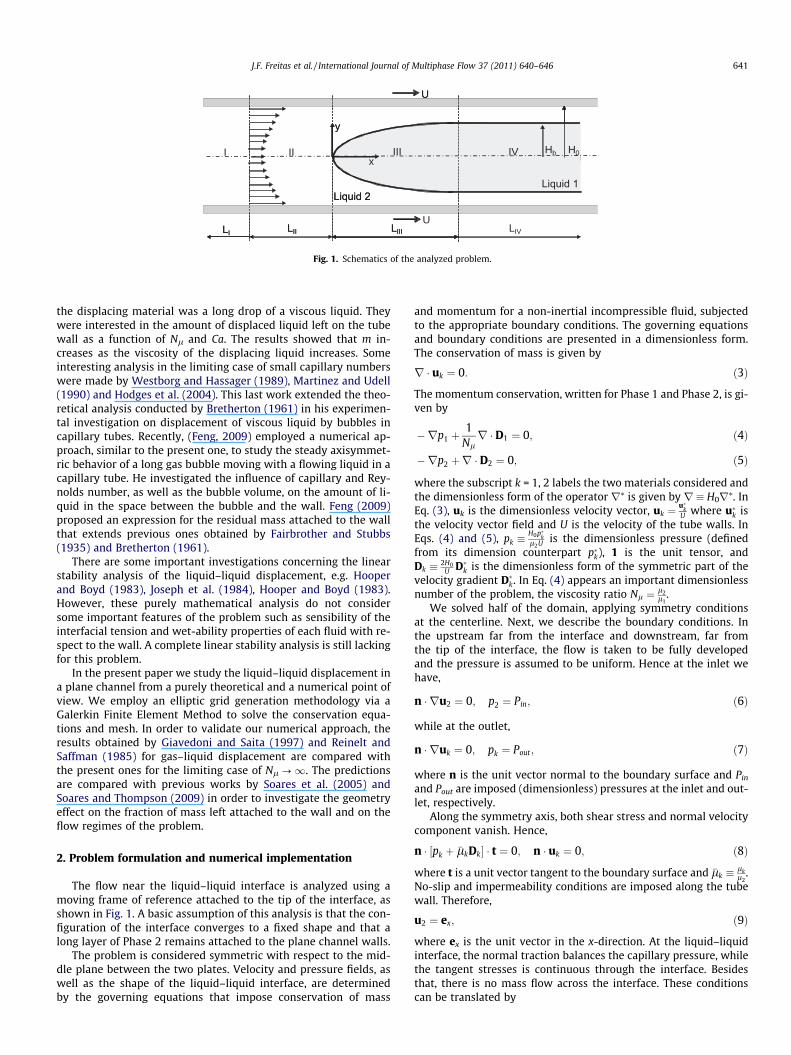
The flow near the liquid–liquid interface is analyzed using amoving frame of reference attached to the tip of the interface, asshown in Fig. 1. A basic assumption of this analysis is that the con-figuration of the interface converges to a fixed shape and that along layer of Phase 2 remains attached to the plane channel walls.
The problem is considered symmetric with respect to the mid-dle plane between the two plates. Velocity and pressure fields, aswell as the shape of the liquid–liquid interface, are determinedby the governing equations that impose conservation of mass
and momentum for a non-inertial incompressible fluid, subjectedto the appropriate boundary conditions. The governing equationsand boundary conditions are presented in a dimensionless form.The conservation of mass is given by
r & uk ! 0: "3#
The momentum conservation, written for Phase 1 and Phase 2, is gi-ven by
'rp1 (1Nl
r & D1 ! 0; "4#
'rp2 (r & D2 ! 0; "5#
where the subscript k = 1, 2 labels the two materials considered andthe dimensionless form of the operator r⁄ is given by r % H0r⁄. InEq. (3), uk is the dimensionless velocity vector, uk !
u$kU where u$
k isthe velocity vector field and U is the velocity of the tube walls. InEqs. (4) and (5), pk %
H0p$kl2U
is the dimensionless pressure (definedfrom its dimension counterpart p$
k), 1 is the unit tensor, andDk % 2H0
U D$k is the dimensionless form of the symmetric part of the
velocity gradient D$k. In Eq. (4) appears an important dimensionless
number of the problem, the viscosity ratio Nl ! l2l1.
We solved half of the domain, applying symmetry conditionsat the centerline. Next, we describe the boundary conditions. Inthe upstream far from the interface and downstream, far fromthe tip of the interface, the flow is taken to be fully developedand the pressure is assumed to be uniform. Hence at the inlet wehave,
n &ru2 ! 0; p2 ! Pin; "6#
while at the outlet,
n &ruk ! 0; pk ! Pout; "7#
where n is the unit vector normal to the boundary surface and Pinand Pout are imposed (dimensionless) pressures at the inlet and out-let, respectively.
Along the symmetry axis, both shear stress and normal velocitycomponent vanish. Hence,
n & )pk ( !lkDk* & t ! 0; n & uk ! 0; "8#
where t is a unit vector tangent to the boundary surface and !lk % lkl2.
No-slip and impermeability conditions are imposed along the tubewall. Therefore,
u2 ! ex; "9#
where ex is the unit vector in the x-direction. At the liquid–liquidinterface, the normal traction balances the capillary pressure, whilethe tangent stresses is continuous through the interface. Besidesthat, there is no mass flow across the interface. These conditionscan be translated by
LI LII LIII LIVLI
II
LII
I
U
LIII
III
U
x
y
Hb H0IV
U
Hb H0VIIIIx
y
Fig. 1. Schematics of the analyzed problem.
J.F. Freitas et al. / International Journal of Multiphase Flow 37 (2011) 640–646 641
n"p1 ' p2# ( n & "D2 '1Nl
D1# !1Ca
nRm
; "10#
where Ca % l2Ur ; Rm ! R$
m=H0 is the dimensionless radius of curva-ture, and
u1 ! u2 ! "uk & t#t: "11#
Hence, the normal-to-the-interface component of the velocity van-ishes. Eq. (10) exhibits the two relevant dimensionless parametersthat govern this problem, Ca and Nl. 1/Rm is the local mean curva-ture defined as
1R$m% rH & n % r & n' "nn &r# & n; "12#
where the operator rH & ( ) is the divergence operator resolved inthe tangential plane defined by n.
The numerical implementation approach used in the presentwork is to transform the set of differential equations and boundaryconditions written for the physical domain into an equivalent set,defined in a known reference domain. This method is largely usedto deal with problems where the flow domain, for each fluid, isunknown a priori. For a complete understanding of the methodemployed the reader is referred to the works of Christodoulouand Scriven (1992), Sackinger et al. (1996) and Dimakopoulosand Tsamopoulos (2003). This transformation is achieved by amapping function x = x(n) that connects the two domains, asshown in Soares and Thompson (2009), where the coordinates nand g of the reference domain satisfy diffusive-like equations. Inthe final mesh architecture, as exemplified by Fig. 2, the domainis divided into 1438 elements that correspond to 5901 nodes and27,918 degrees of freedom.
3. Theoretical analysis
In this section we present two interesting results extracted froma theoretical analysis on the fully developed flow in Regions I andIV sketched in Fig. 1. The first one is an alternative way to calculatethe residual mass fraction, m, in terms of the pressure gradients inthe fully developed regions, dp
dx jI anddpdx jIV . The second result is an
expression for the critical mass fraction, mc, in terms of the viscos-ity ratio Nl. The step-by-step procedure to find these two results isthe same conducted by Soares and Thompson (2009), where moredetails are given.
To obtain m as a function of the pressure gradient in Region IV,dpdx jIV , the flow rate of the Phase 1 in this region must be obtained.Applying the mass conservation, QIV
1 ! 0! "
, we find.
m ! 1'
###################################1 dp
dx
! $$$$
IV
. "' 3=2
Nl ' 3=2
vuut; "13#
where dpdx j
$IV is the dimensionless pressure gradient in Region IV de-
fined, here, as dpdx j
$IV ! H2
03l2U
& dpdx jIV . Similarly, the flow rate of Phase 2
in regions I and IV can be obtained and the mass conservation con-dition QI
2 ! QIV2
! "leads to Eq. (14) that relates m with the pressure
gradients on Region I and Region IV.
dpdx
$$$$$
I! 1'm' dp
dx
$$$$$
IV
32"1'm# ' 1
2"1'm#3 ' 1
% &; "14#
Eqs. (13) and (14) are alternative expressions to calculatem and canbe useful in experiments where optical devices are useless due toreflection and refraction properties of the two fluids.
The critical fraction of mass, mc, see (Taylor, 1961), can be ob-tained by assuming that the velocity of Phase 2 vanishes at the cen-ter line in Region I, uI
2"0# ! 0. Hence, the critical fraction of massthe fraction of mass in the limiting case between a reversing anda non-reversing flow.
mc !1
3"1' 1Nl#; "15#
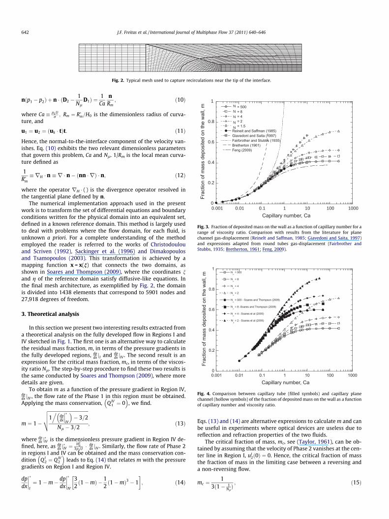
Fig. 2. Typical mesh used to capture recirculations near the tip of the interface.
0
0.2
0.4
0.6
0.8
1
0.001 0.01 0.1 1 10 100 1000
N
N
N
N
N
Fig. 3. Fraction of deposited mass on the wall as a function of capillary number for arange of viscosity ratio. Comparison with results from the literature for planechannel gas-displacement (Reinelt and Saffman, 1985; Giavedoni and Saita, 1997)and expressions adapted from round tubes gas-displacement (Fairbrother andStubbs, 1935; Bretherton, 1961; Feng, 2009).
Fig. 4. Comparison between capillary tube (filled symbols) and capillary planechannel (hollow symbols) of the fraction of deposited mass on the wall as a functionof capillary number and viscosity ratio.
642 J.F. Freitas et al. / International Journal of Multiphase Flow 37 (2011) 640–646
Eq. (15) is the equivalent expression, concerning liquid–liquid dis-placement in plane channels, of the result given by Soares andThompson (2009) for the case liquid–liquid displacement in capil-lary tubes. When Nl ?1 the critical mass fraction for gas–liquiddisplacement in plane channels is obtained, mc = 1/3, in contrastto mc = 1/2 for displacement in capillary tubes. Additionally, asthe condition m 6 1 must be satisfied, the critical condition is neverreached for Nl 6 3/2. Soares and Thompson (2009) found Nl 6 2 forliquid–liquid displacement in capillary tubes.
4. Results and discussion
We present here results for the residual mass left attached tothe wall of the plates and the different flow patterns of the prob-lem as functions of the capillary number, Ca, and the viscosity ratioNl. The values of viscosity ratio were chosen Nl = 1.5; 2; 4; 8; 500in order to make a direct comparison with the results presented bySoares et al. (2005) and Soares and Thompson (2009) for displace-ment in capillary tubes. Hence, the effect of changing from cylin-drical to rectangular geometry can be observed.
4.1. Fraction of mass m
Fig. 3 shows the residual mass fraction, m, as a function of cap-illary number, Ca, for the chosen values of viscosity ratio. ForNl = 500 the liquid–liquid displacement tends to gas–liquid, there-fore, the previous predictions presented by Giavedoni and Saita(1997) and Reinelt and Saffman (1985) to validate the presentones. We can see that the agreement is quite good with a relativedifference less than 1%. Decreasing Nl, the residual mass fractionincreases over the entire range of capillary number. We can notethat m reaches asymptotic values at high capillary numbers. Thisasymptotic behavior was expected in face of the dimensionlessforce balance at the interface, Eq. (10). As Ca?1 the stress jumpat the interface vanishes and the capillary forces become negligi-ble. For Nl = 1.5 we have not reached values of capillary numberabove Ca = 10. In fact that value of viscosity ratio divides the prob-lem into two branches in the same fashion as reported by Lac andSherwood (2009) and Soares and Thompson (2009), indepen-dently, for Nl = 2 in the case of capillary tube. From the analysisconducted by Lac and Sherwood (2009), this value of viscosity ratiois, probably, related to physical instabilities on the interface.
0
0.2
0.4
0.6
0.8
1
0.001 0.01 0.1 1 10 100 1000
N
N
N
N
N
N
N
N
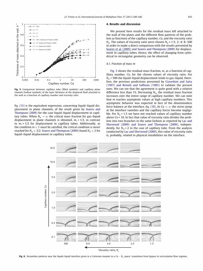
Fig. 5. Comparison between capillary tube (filled symbols) and capillary planechannel (hollow symbols) of the layer thickness of the displaced fluid attached tothe wall as a function of capillary number and viscosity ratio.
Fig. 6. Streamline patterns near the liquid–liquid interface given in a Cartesian manner in a Ca ' Nl space: transitions from bypass to recirculation flow regimes.
J.F. Freitas et al. / International Journal of Multiphase Flow 37 (2011) 640–646 643
To justify the tendency of Ca and Nl, an heuristic explanation,based on the dimensionless form of the force balance equation atthe interface, is offered by Sousa et al. (2007).
One of the aims of the present work is to investigate the effectof changing the geometry from cylindrical to rectangular on theoutput results. Due to the differences between plane and tubechannels, related to the quantitiesm and h⁄ we make a comparisonbetween the two geometries using both quantities.
Fig. 4 shows such a comparison for the fraction of mass of Phase2 attached to the wall. We can see that, from this perspective, theplane channel has higher displacement efficiency, less amount ofresidual liquid left behind. Qualitatively, the two sets of curves,hollow symbols for the Cartesian 2-D geometry, and filled symbolsfor axis-symmetric one, each of them formed by the same levels ofviscosity ratio, are very similar. They differ basically by a transla-tion in the (Ca,m) space. However, the translation is not negligible.The difference between the fraction of mass of a capillary tube tothe plane channel can achieve 45% in some cases. This result showsthat for fixed capillary number and viscosity ratio, the displace-ment efficiency is higher when the passages have a large aspect ra-tio, i.e. when they are slits.
The dimensionless layer thickness is depicted in Fig. 5 for thesame two sets of viscosity ratios. The difference between the hol-low symbols and filled symbols curves corresponding to the sameviscosity ratio is not that big. Interestingly, we observe that h⁄ is
lower for the tube geometry if we compare two curves with thesame viscosity ratio. However, there is an exception, which is ex-actly Nl = 2, where the tube layer thickness is higher than theplane channel one. In this case the two curves associated to eachgeometry match for a higher range of Ca. We can also notice that,for low values of capillary number, the two sets of curves collapseinto a single master curve. Since we can relate h⁄ and m from thecase of a capillary tube as h$ ! 1'
#############1'm
p, the results displayed
in Figs. 6 and 7 allow us to transpose the analysis of Fairbrotherand Stubbs (1935), Bretherton (1961) and Feng (2009) and to pro-pose analogous relations between dimensionless layer thickness asa function of capillary number in the limit of small Ca as
h$FS ! 1'
##################1'
######Ca
pq"16#
and
h$B ! 1'
##############################1' 2:68Ca2=3
p"17#
and
h$F ! 1'
#######################################################1' 0:6202
"1( 0:1946Ca'0:7111#
s; "18#
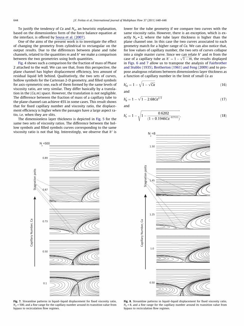
Fig. 7. Streamline patterns in liquid–liquid displacement for fixed viscosity ratio,Nl = 500, and a fine range for the capillary number around its transition value frombypass to recirculation flow regimes.
Fig. 8. Streamline patterns in liquid–liquid displacement for fixed viscosity ratio,Nl = 8, and a fine range for the capillary number around its transition value frombypass to recirculation flow regimes.
644 J.F. Freitas et al. / International Journal of Multiphase Flow 37 (2011) 640–646
where h$FS; h$
B and h$F are the dimensionless layer thickness for the
plane channel geometry from the propositions presented by Fair-brother and Stubbs (1935), Bretherton (1961) and Feng (2009),respectively. Fig. 3 shows that these expressions may indeed beadapted to the planar channel case for low values of capillary num-ber. The adaptation from Feng’s expression, h$
F , follows the sametendency even for high Ca. It is the only expression that has aninflection point and, therefore a possible plateau for high valuesof capillary number.
4.2. Streamline patterns
Fig. 6 illustrates a set of examples of the streamlines in theneighborhood of the front of the drop with the reference frame at-tached to the tip of the interface between the two liquids. This fig-ure shows the influence of the viscosity ratio and capillary numberon the different flow patterns the problem presents. These patternscan be roughly classified, see (Taylor, 1961), into bypass, whenthere is no recirculation of the displaced fluid; transition, whenthere appears a recirculation in the displaced fluid; and full-recircu-lating, when this recirculation occupies the whole displaced do-main and there is a presence of a secondary recirculation on thedisplacing fluid. The spectrum of capillary numbers chosen wasCa = 0.1, 0.5, 1.0, 2.0, 5.0, 10.0, 35.0 with the same values of viscos-
ity ratio used to compute the residual mass fraction, Nl = 1.5; 2; 4;8; 500.
The same effect reported by Soares and Thompson (2009) incapillary tubes are observed here, for higher values of the capillarynumber and higher values of the viscosity ratio the bypass regimeis observed. On the other side of this tendency, lower values of Caand Nl, the cases are of full-recirculating flow where a secondaryrecirculation appears within the displacing fluid domain near thefinger tip. For Nl = 1.5 the problem does not present the bypassflow regime, as predicted.
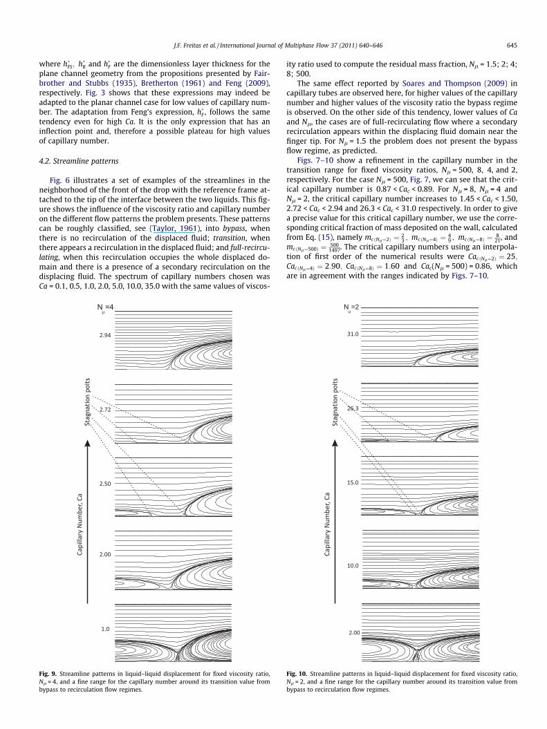
Figs. 7–10 show a refinement in the capillary number in thetransition range for fixed viscosity ratios, Nl = 500, 8, 4, and 2,respectively. For the case Nl = 500, Fig. 7, we can see that the crit-ical capillary number is 0.87 < Cac < 0.89. For Nl = 8, Nl = 4 andNl = 2, the critical capillary number increases to 1.45 < Cac < 1.50,2.72 < Cac < 2.94 and 26.3 < Cac < 31.0 respectively. In order to givea precise value for this critical capillary number, we use the corre-sponding critical fraction of mass deposited on the wall, calculatedfrom Eq. (15), namely mc"Nl!2# ! 2
3 ; mc"Nl!4# ! 49 ; mc "Nl!8# ! 8
21, andmc "Nl!500# ! 500
1497. The critical capillary numbers using an interpola-tion of first order of the numerical results were Cac "Nl!2# ! 25;Cac"Nl!4# ! 2:90; Cac "Nl!8# ! 1:60 and Cac(Nl = 500) = 0.86, whichare in agreement with the ranges indicated by Figs. 7–10.
Fig. 9. Streamline patterns in liquid–liquid displacement for fixed viscosity ratio,Nl = 4, and a fine range for the capillary number around its transition value frombypass to recirculation flow regimes.
Fig. 10. Streamline patterns in liquid–liquid displacement for fixed viscosity ratio,Nl = 2, and a fine range for the capillary number around its transition value frombypass to recirculation flow regimes.
J.F. Freitas et al. / International Journal of Multiphase Flow 37 (2011) 640–646 645
5. Final remarks
A theoretical and numerical analysis has been conducted in theproblem of the liquid–liquid displacement of two immiscible vis-cous fluids in a plane channel for the case where a film of the dis-placed fluid remains attached to the wall as the displacing fluidmoves.
Using the same theoretical procedure conducted by Soares andThompson (2009), we found an expression for the critical fractionof mass,mc, in terms of viscosity ratio, Eq. (15), and two alternativeequations to calculate the residual mass in terms of pressure gra-dients in the fully developed flow in Regions I and IV, Eqs. (14)and (13). These theoretical equations agree quite well with thenumerical results.
The two main aspects of the numerical results are: the residualmass deposited on the wall and the streamlines the problem exhib-its. Results for the residual mass were compared to the ones pre-sented by Soares and Thompson (2009) who analyze the case ofliquid–liquid displacement in capillary tubes. Therefore, besidescapillary number and viscosity ratio, we can study the influenceof the geometry through a comparison between the two extremevalues of aspect ratio. In general it is observed the same tendencyfor m with respect to capillary number and viscosity ratio, i.e. anincrease of residual mass with increase of Ca and decrease of Nl.However, the level of mass attached to the wall is quite smallerfor the present case, displacement in plane channels. In order tomake a full comparison we have also compared the results ob-tained for the layer thickness, h⁄, of the capillary tube. We havefound, for the range investigated, that when Nl > 2, h$
T < h$PC , while
for Nl ! 2;h$T > h$
PC . The coincidence of tube and plane channeldimensionless layer thickness of Phase 2 at Region IV, for low val-ues of capillary number, allows the use of the theoretical andempirical proposition of Bretherton (1961), Fairbrother and Stubbs(1935) and Feng (2009) to have analytical expressions for h⁄ in thislimit (Ca < 1) . Concerning the second block, a set of streamline pat-terns near the tip of the interface was shown in a Cartesian frame(Ca,Nl) for a wide range of these two parameters. This map showsthe range of capillary number and viscosity ratio where the streampatterns evolve from full-recirculating to bypass flow regime.
Finally, the theoretical and numerical results indicate thatNl = 1.5 divides the problem into two branches. This is the criticalvalue, analogous to Nl = 2 for capillary tubes, found by Lac andSherwood (2009) and Soares and Thompson (2009).
Acknowledgments
This research was partially funded by grants from CNPq (Conse-lho Nacional de Pesquisa e Desenvolvimento), ANP (Agência Nac-ional de Petróleo) and PETROBRAS).
References
Bretherton, F.P., 1961. The motion of long bubble in tubes. J. Fluid Mech. 10, 166–188.
Christodoulou, K.N., Scriven, L.E., 1992. Discretization of free surface flows andother moving boundary. J. Comput. Phys. 99, 39–55.
Dimakopoulos, Y., Tsamopoulos, J., 2003. A quasi-elliptic transformation for movingboundary problems with large anisotropic deformations. J. Comput. Phys. 192,494–522.
Fairbrother, F., Stubbs, A.E., 1935. J. Chem. Soc. 1, 527.Feng, J.Q., 2009. A long gas bubble moving in a tube with flowing liquid. Int. J.
Multiphase Flow. 35, 738–746.Giavedoni, M.D., Saita, F.A., 1997. The axisymmetric and plane cases of a gas phase
steadily displacing a Newtonian liquid – a simultaneous solution of thegoverning equations. Phys. Fluids 9, 2420–2428.
Goldsmith, H.L., Mason, S.G., 1963. The flow of suspensions through tubes. J. ColloidSci. 18, 237–261.
Hodges, S., Jenseng, O., Rallison, J., 2004. The motion of a viscous drop through acylindrical tube. J. Fluid Mech. 501, 279–301.
Hooper, A.P., Boyd, W.G.C., 1983. Shear-flow instability at the interface betweentwo viscous fluids. J. Fluid Mech. 128, 507–528.
Hooper, A.P., Boyd, W.G.C., 1983. Shear-flow instability due to a wall and a viscositydiscontinuity at the interface. J. Fluid Mech. 128, 201–225.
Joseph, D.D., Renardy, M., Renardy, Y., 1984. Instability of the flow of twoimmiscible liquids with different viscosity in a pipe. J. Fluid Mech. 141, 309–317.
Lac, E., Sherwood, J.D., 2009. Motion of a drop along the centreline of a capillary in apressure-driven flow. J. Fluid Mech. 640, 27–54.
Martinez, M., Udell, K., 1990. Axisymmetric creeping motion of drops throughcircular tubes. J. Fluid Mech. 210, 565–591.
Reinelt, D.A., Saffman, P.G., 1985. The penetration of a finger into a viscous fluid in achannel and tube. SIAM J. Sci. Stat. Comput. 6, 542–561.
Sackinger, P.A., Shunk, P.R., Rao, R.R., 1996. A Newton–Rhaphson pseudo-soliddomain mapping technique for free and moving boundary problems: a finiteelement implementation. J. Comput. Phys. 125, 83–103.
Soares, E., Thompson, R., 2009. Flow regimes for the immiscible liquid–liquiddisplacement in capillary tubes with complete wetting of the displaced liquid. J.Fluid Mech. 641, 63–84.
Soares, E.J., Carvalho, M.S., Souza Mendes, P.R., 2005. Immiscible liquid–liquiddisplacement in capillary tubes. J. Fluids Eng. 127, 24–31.
Sousa, D., Soares, E., Queiroz, R., Thompson, R., 2007. Numerical investigation ongas-displacement of a shear-thinning liquid and a visco-plastic material incapillary tubes. J. Non-Newtonian Fluid Mech. 144, 149–159.
Taylor, G.I., 1961. Deposition of a viscous fluid on the wall a tube. J. Fluid Mech. 10,161–165.
Westborg, H., Hassager, O., 1989. Creeping motion of long bubbles and drops incapillary tubes. J. Colloid Int. Sci. 133, 135–147.
646 J.F. Freitas et al. / International Journal of Multiphase Flow 37 (2011) 640–646
Related Documents