TABLE OF CONTENTS Ultra Classic (VT) Series Residential Vertical Two-Stage Geothermal Heat Pumps Installation, Operation & Maintenance Instructions 69197343 Revision: 07/07/05D ECM Fan Control 14 ECM Blower Data 16 Electrical - Low Voltage 16 Freeze Protection Selection 16 Water Valve Wiring 17 Thermostat Wiring 17 Electrical Wiring Schematic 18 CXM Control Description 19 Troubleshooting Information 22 Troubleshooting Analysis 23 Major Replacement Components 24 Unit Start-Up Procedure 26 Operating Limits 26 Pressure Drop Table 28 Operating Pressures 28 Warranty 31 Preventive Maintenance BC Model Nomenclature 2 Storage 2 Pre-Installation 3 Physical Data 3 Physical Dimensions 4 Unit Installation 5 Duct System 5 Water Connections 6 Condensate Drain 6 Ground Loop Application 7 Flushing 7 Antifreeze 8 Open Loop/Well Water Installation 9 Water Quality Standards 10 Hybrid Loop/Well Applications 10 Hot Water Generator 11 Electrical - Line Voltage 13 Electrical Data 13

Welcome message from author
This document is posted to help you gain knowledge. Please leave a comment to let me know what you think about it! Share it to your friends and learn new things together.
Transcript
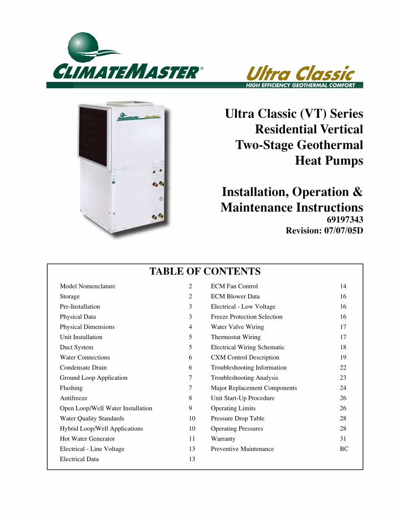
TABLE OF CONTENTS
Ultra Classic (VT) SeriesResidential Vertical
Two-Stage GeothermalHeat Pumps
Installation, Operation &Maintenance Instructions
69197343Revision: 07/07/05D
ECM Fan Control 14
ECM Blower Data 16
Electrical - Low Voltage 16
Freeze Protection Selection 16
Water Valve Wiring 17
Thermostat Wiring 17
Electrical Wiring Schematic 18
CXM Control Description 19
Troubleshooting Information 22
Troubleshooting Analysis 23
Major Replacement Components 24
Unit Start-Up Procedure 26
Operating Limits 26
Pressure Drop Table 28
Operating Pressures 28
Warranty 31
Preventive Maintenance BC
Model Nomenclature 2
Storage 2
Pre-Installation 3
Physical Data 3
Physical Dimensions 4
Unit Installation 5
Duct System 5
Water Connections 6
Condensate Drain 6
Ground Loop Application 7
Flushing 7
Antifreeze 8
Open Loop/Well Water Installation 9
Water Quality Standards 10
Hybrid Loop/Well Applications 10
Hot Water Generator 11
Electrical - Line Voltage 13
Electrical Data 13
Page 2 Ultra Classic (VT) Series
GENERAL INFORMATION
StorageCAUTION: DO NOT store or install units in corrosive environments or in locations subject to temperature or humidity extremes (e.g., attics, garages, rooftops, etc.). Corrosive conditions and high temperature or humidity can significantly reduce performance, reliability, and service life. Always move units in an upright position. Tilting units on their sides may cause equipment damage.
Equipment should be stored in its shipping carton in a clean, dry area. Store units in an upright position at all times. Stack vertical units a maximum of 2 units high. DO NOT remove equipment from shipping cartons until equipment is required for installation.
Unit ProtectionCover units on the job site with either shipping cartons, vinyl film, or an equivalent protective covering. Cap the open ends of pipes stored on the job site. In areas where painting, plastering, or spraying has not been completed, all due precautions must be taken to avoid physical damage to the units and contamination by foreign material. Physical damage and contamination may prevent proper start-up and may result in costly equipment cleanup.
Examine all pipes, fittings, and valves before installing any of the system components. Remove any dirt or trash found in or on these components.
InspectionUpon receipt of the equipment, carefully check the shipment against the bill of lading. Make sure all units have been received. Inspect the carton or crating of each unit, and inspect each unit for damage. Assure the carrier makes proper notation of any shortages or damage on all copies of the freight bill and he completes a common carrier inspection report. Concealed damage not discovered during unloading must be reported to the carrier within 15 days of receipt of shipment. If not filed within 15 days, the freight company can deny the claim without recourse. Note: It is the responsibility of the purchaser to file all necessary claims with the carrier. Notify the ClimateMaster Customer Service of all damage within fifteen (15) days of shipment.
IntroductionClimateMaster UltraClassic Geothermal Heat Pump units are typically installed in a floor level closet, basement, or in a small mechanical room. The installation site chosen for these units must allow adequate clearance for maintenance and servicing of the unit without its removal from the installation location.
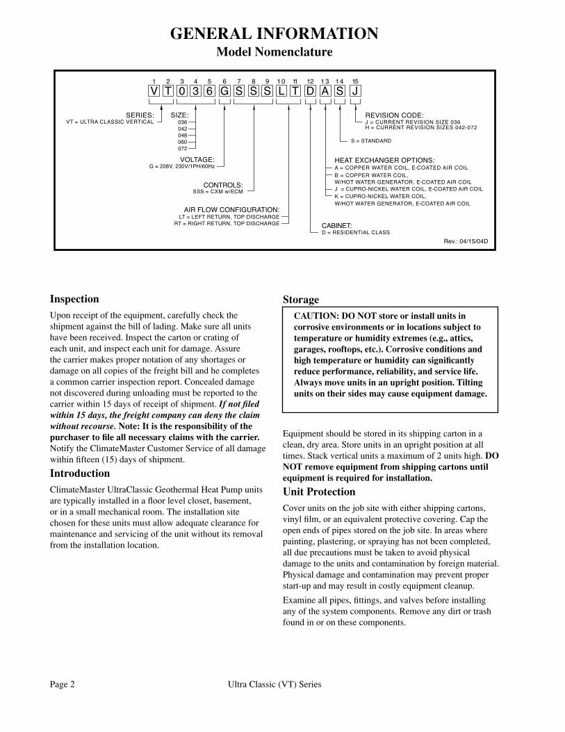
Model Nomenclature
CONTROLS:
048
G=208V,230V/1PH/60Hz
060072
SSS=CXMw/ECM
VT=ULTRACLASSICVERTICAL
VOLTAGE:
SIZE:
042036
SERIES:
V1
T2
03
34
G6
65
S7
S8
S9
D=RESIDENTIALCLASS
LT=LEFTRETURN,TOPDISCHARGE
REVISIONCODE:
AIRFLOWCONFIGURATION:
HEATEXCHANGEROPTIONS:
D121 0
L T11 1 3
A S1 4
CABINET:
J15
J=CURRENTREVISIONSIZE036H=CURRENTREVISIONSIZES042-072
B=COPPERWATERCOIL,W/HOTWATERGENERATOR,E-COATEDAIRCOIL
A=COPPERWATERCOIL,E-COATEDAIRCOIL
J=CUPRO-NICKELWATERCOIL,E-COATEDAIRCOILK=CUPRO-NICKELWATERCOIL,W/HOTWATERGENERATOR,E-COATEDAIRCOIL
S=STANDARD
RT=RIGHTRETURN,TOPDISCHARGE
Rev.:04/15/04D
Ultra Classic (VT) Series Page 3
To avoid equipment damage, DO NOT use these units as a source of heating or cooling during the construction process. The mechanical components and filters used in these units will quickly become clogged with construction dirt and debris which may cause system damage.
To avoid the release of refrigerant into the atmosphere, the refrigerant circuit of this unit must be serviced only by technicians who meet local, state and federal proficiency requirements.
All refrigerant discharged from this unit must be recovered WITHOUT EXCEPTION. Technicians must follow industry accepted guidelines and all local, state and federal statutes for the recovery and disposal of refrigerants.
If a compressor is removed from this unit, system refrigerant circuit oil will remain in the compressor. To avoid leakage of compressor oil, the refrigerant lines of the compressor must be sealed after it is removed.
The installation of geothermal heat pump units and all associated components, parts and accessories which make up the installation shall be in accordance with the regulations of ALL authorities having jurisdiction and MUST conform to all applicable codes. It is the responsibility of the Installing Contractor to determine and comply with ALL applicable codes and regulations.
Pre-InstallationInstallation, operation and maintenance instructions are provided with each unit. Before unit start-up, read all manuals and become familiar with the unit and its operation. Thoroughly check the system before operation.
Prepare units for installation as follows:
1. Compare the electrical data on the unit nameplate with ordering and shipping information to verify the correct unit has been shipped.
2. Keep the cabinet covered with the shipping carton until installation is complete and all plastering, painting, etc., is finished.
3. Verify refrigerant tubing is free of kinks or dents and that it does not touch other unit components.
4. Inspect all electrical connections. Connections must be clean and tight at the terminals.
Remove Fan Motor shipping bracket in rear of Air Handler compartment.
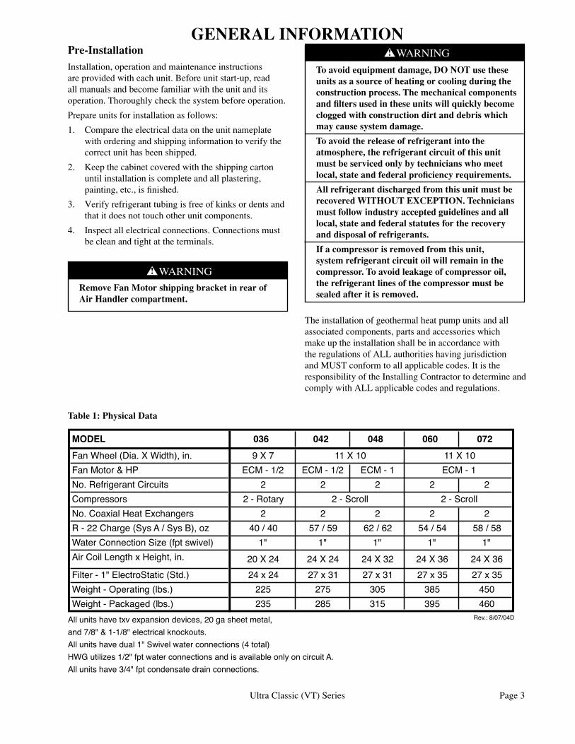
Table 1: Physical Data
VTPhysicalData
MODEL 036 042 048 060 072FanWheel(Dia.XWidth),in. 9X7FanMotor&HP ECM-1/2 ECM-1/2 ECM-1No.RefrigerantCircuits 2 2 2 2 2Compressors 2-RotaryNo.CoaxialHeatExchangers 2 2 2 2 2R-22Charge(SysA/SysB),oz 40/40 57/59 62/62 54/54 58/58WaterConnectionSize(fptswivel) 1" 1" 1" 1" 1"AirCoilLengthxHeight,in. 20X24 24X24 24X32 24X36 24X36Filter-1"ElectroStatic(Std.) 24x24 27x31 27x31 27x35 27x35Weight-Operating(lbs.) 225 275 305 385 450Weight-Packaged(lbs.) 235 285 315 395 460
Rev.:8/07/04DAllunitshavetxvexpansiondevices,20gasheetmetal,and7/8"&1-1/8"electricalknockouts.Allunitshavedual1"Swivelwaterconnections(4total)HWGutilizes1/2"fptwaterconnectionsandisavailableonlyoncircuitA.Allunitshave3/4"fptcondensatedrainconnections.
Revision DateDatafromTomNorth9/00 10/30/00ChangedfilterrackandfilterdatacheckedwithEnertech 11/13/00Changesfornewcompin036,060,and072andElectrostFilter&RackStd 3/30/01
2-Scroll
11X10 11X10ECM-1
2-Scroll
RemovedAirCoilData 8/07/04
GENERAL INFORMATION
Page 4 Ultra Classic (VT) Series
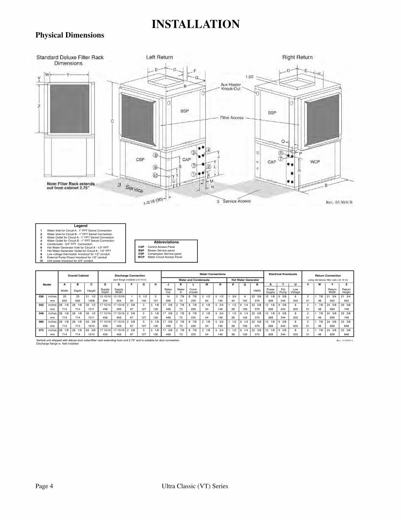
Physical DimensionsINSTALLATION
��������������� �������������������� ����������������� �������������������� �����������������������������������������������±��������
����� � � � � � � � � � � � � � � � � � � � � � � �
����� ����� ������ �����������
�����������
��������
�������
����������� ��� �����
���������
�������
������������������
������������
��� ������ �� �� �� ��� �������� �������� � � ��� � �� � ��� � ��� � ��� � ��� � ��� � �� ��� �� ��� � ��� � � � ��� �� ��� �� ���
�� ��� ��� ���� ��� ��� �� ��� ��� ��� �� ��� �� ��� �� ��� ��� ��� ��� ��� �� �� ��� ���
��� ������ �� ��� �� ��� �� ��� �������� �������� � ��� � � ��� �� ��� � ��� � ��� � ��� � ��� � ��� � ��� �� ��� �� ��� � ��� � � � ��� �� ��� �� ���
�� ��� ��� ���� ��� ��� �� ��� ��� ��� �� ��� �� ��� �� ��� ��� ��� ��� ��� �� �� ��� ���
��� ������ �� ��� �� ��� �� ��� �������� �������� � ��� � � ��� �� ��� � ��� � ��� � ��� � ��� � ��� � ��� �� ��� �� ��� � ��� � � � ��� �� ��� �� ���
�� ��� ��� ���� ��� ��� �� ��� ��� ��� �� ��� �� ��� �� ��� ��� ��� ��� ��� �� �� ��� ���
��� ������ �� ��� �� ��� �� ��� �������� �������� � ��� � � ��� �� ��� � ��� � ��� � ��� � ��� � ��� � ��� �� ��� �� ��� � ��� � � � ��� �� ��� �� ���
�� ��� ��� ���� ��� ��� �� ��� ��� ��� �� ��� �� ��� �� ��� ��� ��� ��� ��� �� �� ��� ���
��� ������ �� ��� �� ��� �� ��� �������� �������� � ��� � � ��� �� ��� � ��� � ��� � ��� � ��� � ��� � ��� �� ��� �� ��� � ��� � � � ��� �� ��� �� ���
�� ��� ��� ���� ��� ��� �� ��� ��� ��� �� ��� �� ��� �� ��� ��� ��� ��� ��� �� �� ��� ���
������������������������������������������������������������������������������������������������������������������������ ����������������������������������������������������
�����������������������±�������� ���������������������������������������
� ����������������������������������������������������� ����������������������������������������������������� ������������������������������������������������������ ������������������������������������������������������ ���������������������������������� ��������������������������������������������������� ���������������������������������������������������� �������������������������������������������������� ����������������������������������������������� ������������������������������������
������
��� ����������������������� ����������������������� ��������������������������� ��������������������������
�������������
�������� ���� ����������������������� �������� ��������������������������������������������� ������� ������������������������������������������������� ������ ������������������������������������������� �������� ���
Ultra Classic (VT) Series Page 5
General Unit LocationLocate the unit in an indoor area that allows easy removal of the filter and access panels, and has enough space for service personnel to perform maintenance or repair. Provide sufficient room to make water, electrical and duct connection(s). If the unit is located in a confined space, such as a closet, provisions must be made for return air to freely enter the space by means of a louvered door, etc. Any access panel screws that would be difficult to remove after the unit is installed should be removed prior to setting the unit. These units are not approved for outdoor installation and, therefore, must be installed inside the structure being conditioned. Do not locate in areas where ambient conditions are not maintained with 40-100°F and up to 75% relative humidity.
Vertical Units Location and AccessVertical Units are typically installed in a floor level closet, basement, or in a small mechanical room. Install units with adequate clearance to allow maintenance and servicing. Conform to the following guidelines when selecting unit location:
1. Provide adequate clearance for filter replacement and drain pan cleaning. Do not block filter access with piping, conduit or other materials. Refer to the unit catalog for Vertical Unit Dimensions.
2. Provide access for fan and fan motor maintenance and for servicing the compressor and coils without removing the unit. Note: UltraClassic compressor and refrigerant circuit service requires that left side access be provided.
3. Provide an unobstructed path to the unit within the closet or mechanical room. Space should be sufficient to allow removal of the unit, if necessary.
4. Provide access to water valves and fittings and screwdriver access to the unit side panels, discharge collar and all electrical connections.
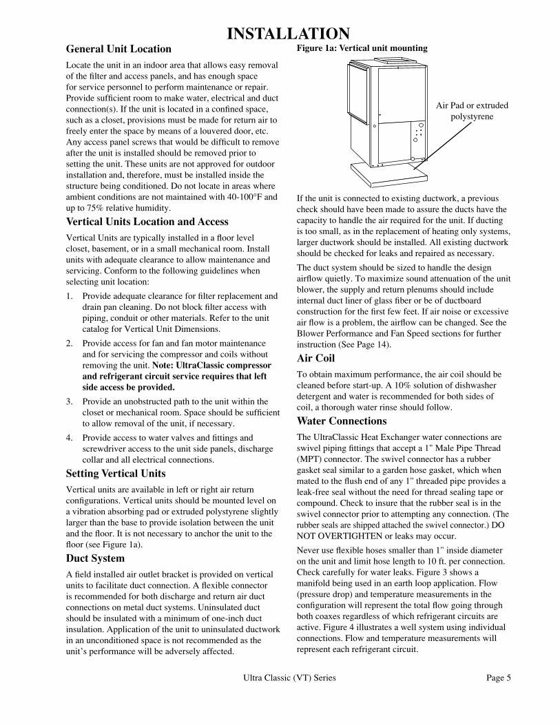
Setting Vertical UnitsVertical units are available in left or right air return configurations. Vertical units should be mounted level on a vibration absorbing pad or extruded polystyrene slightly larger than the base to provide isolation between the unit and the floor. It is not necessary to anchor the unit to the floor (see Figure 1a).
Duct SystemA field installed air outlet bracket is provided on vertical units to facilitate duct connection. A flexible connector is recommended for both discharge and return air duct connections on metal duct systems. Uninsulated duct should be insulated with a minimum of one-inch duct insulation. Application of the unit to uninsulated ductwork in an unconditioned space is not recommended as the unit’s performance will be adversely affected.
INSTALLATIONFigure 1a: Vertical unit mounting
If the unit is connected to existing ductwork, a previous check should have been made to assure the ducts have the capacity to handle the air required for the unit. If ducting is too small, as in the replacement of heating only systems, larger ductwork should be installed. All existing ductwork should be checked for leaks and repaired as necessary.
The duct system should be sized to handle the design airflow quietly. To maximize sound attenuation of the unit blower, the supply and return plenums should include internal duct liner of glass fiber or be of ductboard construction for the first few feet. If air noise or excessive air flow is a problem, the airflow can be changed. See the Blower Performance and Fan Speed sections for further instruction (See Page 14).
Air CoilTo obtain maximum performance, the air coil should be cleaned before start-up. A 10% solution of dishwasher detergent and water is recommended for both sides of coil, a thorough water rinse should follow.
Water ConnectionsThe UltraClassic Heat Exchanger water connections are swivel piping fittings that accept a 1" Male Pipe Thread (MPT) connector. The swivel connector has a rubber gasket seal similar to a garden hose gasket, which when mated to the flush end of any 1" threaded pipe provides a leak-free seal without the need for thread sealing tape or compound. Check to insure that the rubber seal is in the swivel connector prior to attempting any connection. (The rubber seals are shipped attached the swivel connector.) DO NOT OVERTIGHTEN or leaks may occur.
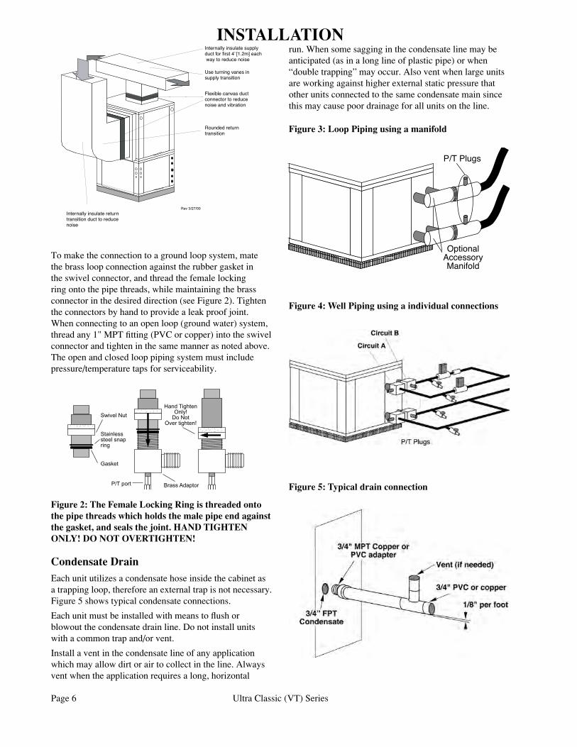
Never use flexible hoses smaller than 1" inside diameter on the unit and limit hose length to 10 ft. per connection. Check carefully for water leaks. Figure 3 shows a manifold being used in an earth loop application. Flow (pressure drop) and temperature measurements in the configuration will represent the total flow going through both coaxes regardless of which refrigerant circuits are active. Figure 4 illustrates a well system using individual connections. Flow and temperature measurements will represent each refrigerant circuit.
Air Pad or extrudedpolystyrene
Page 6 Ultra Classic (VT) Series
Condensate DrainEach unit utilizes a condensate hose inside the cabinet as a trapping loop, therefore an external trap is not necessary. Figure 5 shows typical condensate connections.
Each unit must be installed with means to flush or blowout the condensate drain line. Do not install units with a common trap and/or vent.
Install a vent in the condensate line of any application which may allow dirt or air to collect in the line. Always vent when the application requires a long, horizontal
����������
�����������������������
������
�������� �������������
�����������������������
�������������
To make the connection to a ground loop system, mate the brass loop connection against the rubber gasket in the swivel connector, and thread the female locking ring onto the pipe threads, while maintaining the brass connector in the desired direction (see Figure 2). Tighten the connectors by hand to provide a leak proof joint. When connecting to an open loop (ground water) system, thread any 1" MPT fitting (PVC or copper) into the swivel connector and tighten in the same manner as noted above. The open and closed loop piping system must include pressure/temperature taps for serviceability.
run. When some sagging in the condensate line may be anticipated (as in a long line of plastic pipe) or when “double trapping” may occur. Also vent when large units are working against higher external static pressure that other units connected to the same condensate main since this may cause poor drainage for all units on the line.
Figure 4: Well Piping using a individual connections
Figure 5: Typical drain connection
Figure 3: Loop Piping using a manifold
P/TPlugs
OptionalAccessoryManifold
Flexiblecanvasductconnectortoreducenoiseandvibration
Useturningvanesinsupplytransition
Internallyinsulatesupplyductforfirst4’eachwaytoreducenoise
Internallyinsulatereturntransitionducttoreducenoise
Roundedreturntransition
Rev.:11/2/00
Flexiblecanvasductconnectortoreducenoiseandvibration
Useturningvanesinsupplytransition
Internallyinsulatesupplyductforfirst4’[1.2m]eachwaytoreducenoise
Internallyinsulatereturntransitionducttoreducenoise
Roundedreturntransition
Rev3/27/00
INSTALLATION
Figure 2: The Female Locking Ring is threaded onto the pipe threads which holds the male pipe end against the gasket, and seals the joint. HAND TIGHTEN ONLY! DO NOT OVERTIGHTEN!
Ultra Classic (VT) Series Page 7
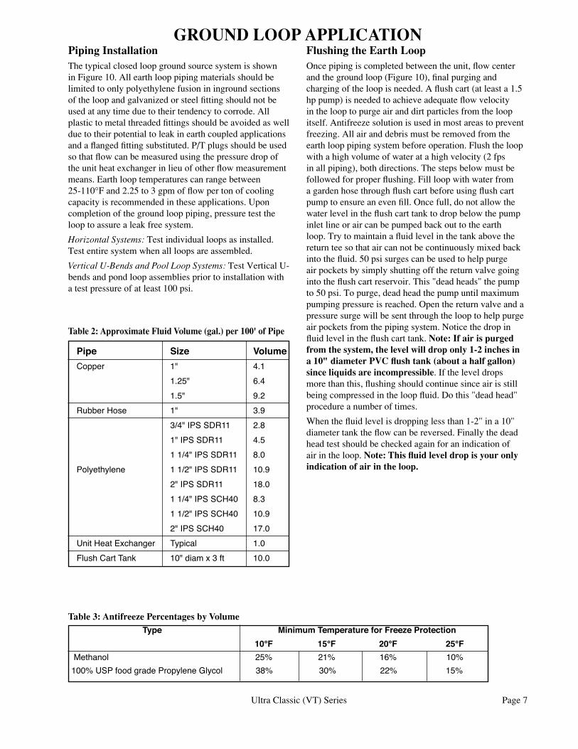
Type MinimumTemperatureforFreezeProtection 10°F 15°F 20°F 25°FMethanol 25% 21% 16% 10%100%USPfoodgradePropyleneGlycol 38% 30% 22% 15%
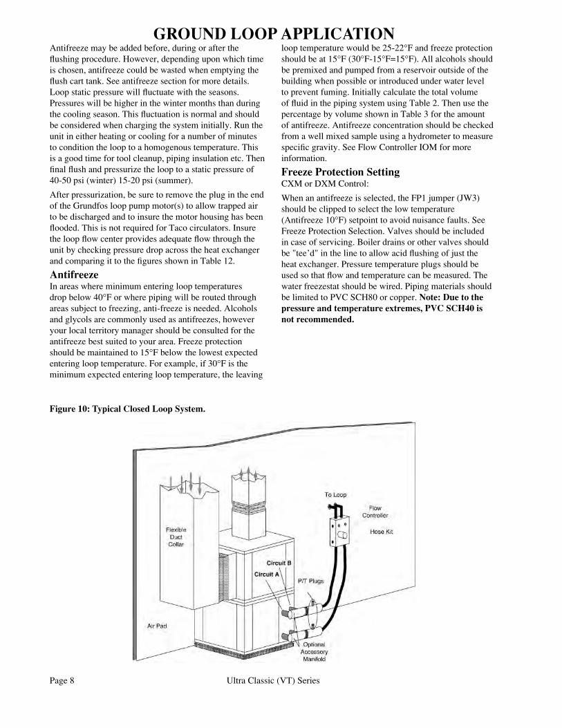
GROUND LOOP APPLICATIONPiping InstallationThe typical closed loop ground source system is shown in Figure 10. All earth loop piping materials should be limited to only polyethylene fusion in inground sections of the loop and galvanized or steel fitting should not be used at any time due to their tendency to corrode. All plastic to metal threaded fittings should be avoided as well due to their potential to leak in earth coupled applications and a flanged fitting substituted. P/T plugs should be used so that flow can be measured using the pressure drop of the unit heat exchanger in lieu of other flow measurement means. Earth loop temperatures can range between 25-110°F and 2.25 to 3 gpm of flow per ton of cooling capacity is recommended in these applications. Upon completion of the ground loop piping, pressure test the loop to assure a leak free system.
Horizontal Systems: Test individual loops as installed. Test entire system when all loops are assembled.
Vertical U-Bends and Pool Loop Systems: Test Vertical U-bends and pond loop assemblies prior to installation with a test pressure of at least 100 psi.
Flushing the Earth LoopOnce piping is completed between the unit, flow center and the ground loop (Figure 10), final purging and charging of the loop is needed. A flush cart (at least a 1.5 hp pump) is needed to achieve adequate flow velocity in the loop to purge air and dirt particles from the loop itself. Antifreeze solution is used in most areas to prevent freezing. All air and debris must be removed from the earth loop piping system before operation. Flush the loop with a high volume of water at a high velocity (2 fps in all piping), both directions. The steps below must be followed for proper flushing. Fill loop with water from a garden hose through flush cart before using flush cart pump to ensure an even fill. Once full, do not allow the water level in the flush cart tank to drop below the pump inlet line or air can be pumped back out to the earth loop. Try to maintain a fluid level in the tank above the return tee so that air can not be continuously mixed back into the fluid. 50 psi surges can be used to help purge air pockets by simply shutting off the return valve going into the flush cart reservoir. This "dead heads" the pump to 50 psi. To purge, dead head the pump until maximum pumping pressure is reached. Open the return valve and a pressure surge will be sent through the loop to help purge air pockets from the piping system. Notice the drop in fluid level in the flush cart tank. Note: If air is purged from the system, the level will drop only 1-2 inches in a 10" diameter PVC flush tank (about a half gallon) since liquids are incompressible. If the level drops more than this, flushing should continue since air is still being compressed in the loop fluid. Do this "dead head" procedure a number of times.
When the fluid level is dropping less than 1-2" in a 10" diameter tank the flow can be reversed. Finally the dead head test should be checked again for an indication of air in the loop. Note: This fluid level drop is your only indication of air in the loop.
Pipe Size Volume Copper 1" 4.1 1.25" 6.4 1.5" 9.2 RubberHose 1" 3.9 3/4"IPSSDR11 2.8 1"IPSSDR11 4.5 11/4"IPSSDR11 8.0 Polyethylene 11/2"IPSSDR11 10.9 2"IPSSDR11 18.0 11/4"IPSSCH40 8.3 11/2"IPSSCH40 10.9 2"IPSSCH40 17.0 UnitHeatExchanger Typical 1.0 FlushCartTank 10"diamx3ft 10.0
Table 2: Approximate Fluid Volume (gal.) per 100' of Pipe
Table 3: Antifreeze Percentages by Volume
Page 8 Ultra Classic (VT) Series
Antifreeze may be added before, during or after the flushing procedure. However, depending upon which time is chosen, antifreeze could be wasted when emptying the flush cart tank. See antifreeze section for more details. Loop static pressure will fluctuate with the seasons. Pressures will be higher in the winter months than during the cooling season. This fluctuation is normal and should be considered when charging the system initially. Run the unit in either heating or cooling for a number of minutes to condition the loop to a homogenous temperature. This is a good time for tool cleanup, piping insulation etc. Then final flush and pressurize the loop to a static pressure of 40-50 psi (winter) 15-20 psi (summer).
After pressurization, be sure to remove the plug in the end of the Grundfos loop pump motor(s) to allow trapped air to be discharged and to insure the motor housing has been flooded. This is not required for Taco circulators. Insure the loop flow center provides adequate flow through the unit by checking pressure drop across the heat exchanger and comparing it to the figures shown in Table 12.
AntifreezeIn areas where minimum entering loop temperatures drop below 40°F or where piping will be routed through areas subject to freezing, anti-freeze is needed. Alcohols and glycols are commonly used as antifreezes, however your local territory manager should be consulted for the antifreeze best suited to your area. Freeze protection should be maintained to 15°F below the lowest expected entering loop temperature. For example, if 30°F is the minimum expected entering loop temperature, the leaving
loop temperature would be 25-22°F and freeze protection should be at 15°F (30°F-15°F=15°F). All alcohols should be premixed and pumped from a reservoir outside of the building when possible or introduced under water level to prevent fuming. Initially calculate the total volume of fluid in the piping system using Table 2. Then use the percentage by volume shown in Table 3 for the amount of antifreeze. Antifreeze concentration should be checked from a well mixed sample using a hydrometer to measure specific gravity. See Flow Controller IOM for more information.
Freeze Protection SettingCXM or DXM Control:
When an antifreeze is selected, the FP1 jumper (JW3) should be clipped to select the low temperature (Antifreeze 10°F) setpoint to avoid nuisance faults. See Freeze Protection Selection. Valves should be included in case of servicing. Boiler drains or other valves should be "tee’d" in the line to allow acid flushing of just the heat exchanger. Pressure temperature plugs should be used so that flow and temperature can be measured. The water freezestat should be wired. Piping materials should be limited to PVC SCH80 or copper. Note: Due to the pressure and temperature extremes, PVC SCH40 is not recommended.
Figure 10: Typical Closed Loop System.
GROUND LOOP APPLICATION
Ultra Classic (VT) Series Page 9
Water QualityWater quality should be plentiful and of good quality. Table 4 shows recommended water quality guidelines. The unit can be ordered with either a copper or cupro-nickel water heat exchanger. Copper is recommended for closed loop systems and open loop ground water systems that are not high in mineral content or corrosiveness. In conditions anticipating heavy scale formation or in brackish water, a cupro-nickel heat exchanger is recommended. In ground water situations where scaling could be heavy or where biological growth such as iron bacteria will be present, a closed loop system is recommended. Heat exchanger coils may over time lose heat exchange capabilities due to a build up of mineral deposits inside. These can be cleaned only by a qualified service mechanic as acid and special pumping equipment are required. Note: Desuperheater coils can likewise become scaled and possibly plugged. In areas with extremely hard water, the home owner should be informed that the heat exchanger may require occasional acid flushing.
Expansion TankUse a closed, bladder-type expansion tank to minimize mineral formation due to air exposure. The expansion tank should be sized to handle at least one minute run time of the pump to prevent premature pump failure using its drawdown capacity rating. The pump should be sized to the home’s domestic water load (5-9 gpm) plus the heat pump water load. Discharge water from the unit is not contaminated in any manner and can be disposed of in various ways, depending on local building codes, i.e. recharge well, storm sewer, drain field, adjacent stream or pond, etc. Most local codes forbid the use of sanitary sewer for disposal. Consult your local building and zoning department to assure compliance in your area.
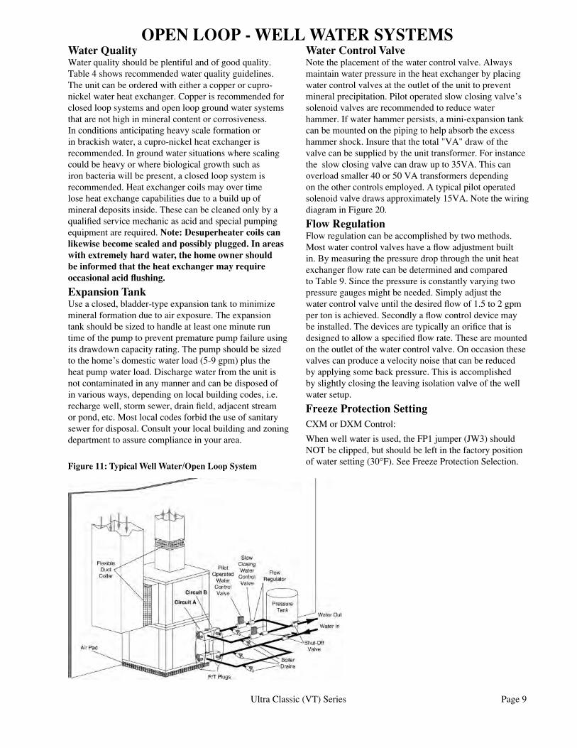
OPEN LOOP - WELL WATER SYSTEMSWater Control Valve Note the placement of the water control valve. Always maintain water pressure in the heat exchanger by placing water control valves at the outlet of the unit to prevent mineral precipitation. Pilot operated slow closing valve’s solenoid valves are recommended to reduce water hammer. If water hammer persists, a mini-expansion tank can be mounted on the piping to help absorb the excess hammer shock. Insure that the total "VA" draw of the valve can be supplied by the unit transformer. For instance the slow closing valve can draw up to 35VA. This can overload smaller 40 or 50 VA transformers depending on the other controls employed. A typical pilot operated solenoid valve draws approximately 15VA. Note the wiring diagram in Figure 20.
Flow RegulationFlow regulation can be accomplished by two methods. Most water control valves have a flow adjustment built in. By measuring the pressure drop through the unit heat exchanger flow rate can be determined and compared to Table 9. Since the pressure is constantly varying two pressure gauges might be needed. Simply adjust the water control valve until the desired flow of 1.5 to 2 gpm per ton is achieved. Secondly a flow control device may be installed. The devices are typically an orifice that is designed to allow a specified flow rate. These are mounted on the outlet of the water control valve. On occasion these valves can produce a velocity noise that can be reduced by applying some back pressure. This is accomplished by slightly closing the leaving isolation valve of the well water setup.
Freeze Protection SettingCXM or DXM Control:
When well water is used, the FP1 jumper (JW3) should NOT be clipped, but should be left in the factory position of water setting (30°F). See Freeze Protection Selection.Figure 11: Typical Well Water/Open Loop System
Page 10 Ultra Classic (VT) Series
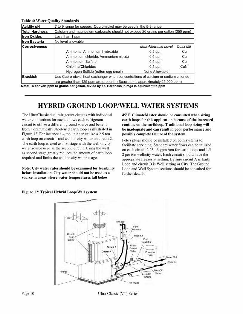
HYBRID GROUND LOOP/WELL WATER SYSTEMSThe UltraClassic dual refrigerant circuits with individual water connections for each, allows each refrigerant circuit to utilize a different ground source and benefit from a dramatically shortened earth loop as illustrated in Figure 12. For instance a 4 ton unit can utilize a 2.5 ton earth loop on circuit 1 and well or city water on circuit 2. The earth loop is used as first stage with the well or city water source used as the second circuit. Using the well as second stage greatly reduces the amount of earth loop required and limits the well or city water usage.
Note: City water rates should be examined for feasibility before installation. City water should not be used as a source in areas where water temperatures fall below
45°F. ClimateMaster should be consulted when sizing earth loops for this application because of the increased runtime on the earthloop. Traditional loop sizing will be inadequate and can result in poor performance and possibly complete failure of the system.
Pete's plugs should be installed on both systems to facilitate servicing. Standard water flows can be utilized on each circuit 2.25 - 3 gpm /ton for earth loops and 1.5-2 per ton well/city water. Each circuit should have the appropriate freezestat setting. Be sure circuit A is Earth Loop and circuit B is Well setting or City. The Ground Loop and Well System sections should be consulted for further details.
Figure 12: Typical Hybrid Loop/Well system
Table 4: Water Quality Standards���������� ���������������������������������������������������������������������������������� ������������������������������������������������������������������������������������������� ���������������������������� ������������������������������� ������������������� ��������
��������������������������� ������� ������������������������������������� ������� ������������������ ������� �������������������� ������� ��������������������������������������� �������������� �
�������� ��������������������������������������������������������������������������������������������������������������������������������������������������������������
����������������������������������������������������������������������������������������������
Ultra Classic (VT) Series Page 11
Shut-offValvewithWasteVentathighpoint
ColdInlet
HotOutlettohome
Insulatedwaterlines-5/8”OD50ftmaximum
PoweredWaterHeater
Upperelementto120 - 130°F
Lowerelementto100-110°F
DomesticColdSupply
Teeanddrain
Shut-offValve
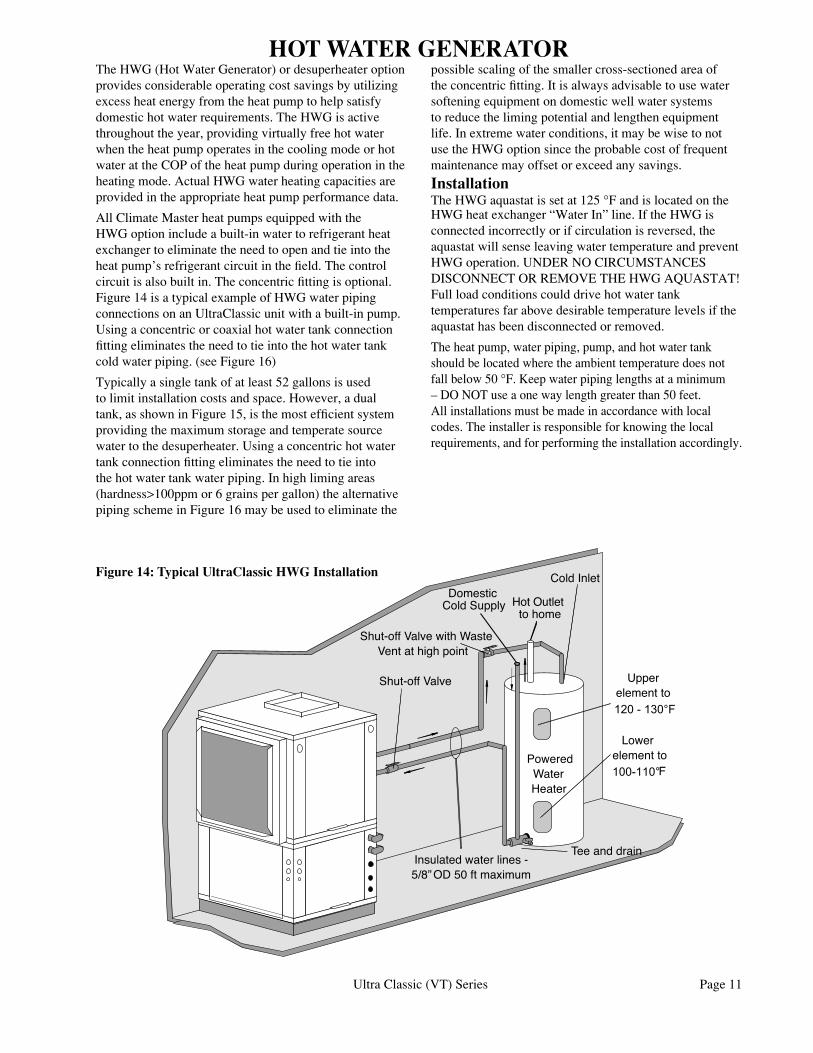
HOT WATER GENERATORThe HWG (Hot Water Generator) or desuperheater option provides considerable operating cost savings by utilizing excess heat energy from the heat pump to help satisfy domestic hot water requirements. The HWG is active throughout the year, providing virtually free hot water when the heat pump operates in the cooling mode or hot water at the COP of the heat pump during operation in the heating mode. Actual HWG water heating capacities are provided in the appropriate heat pump performance data.
All Climate Master heat pumps equipped with the HWG option include a built-in water to refrigerant heat exchanger to eliminate the need to open and tie into the heat pump’s refrigerant circuit in the field. The control circuit is also built in. The concentric fitting is optional. Figure 14 is a typical example of HWG water piping connections on an UltraClassic unit with a built-in pump.Using a concentric or coaxial hot water tank connection fitting eliminates the need to tie into the hot water tank cold water piping. (see Figure 16)
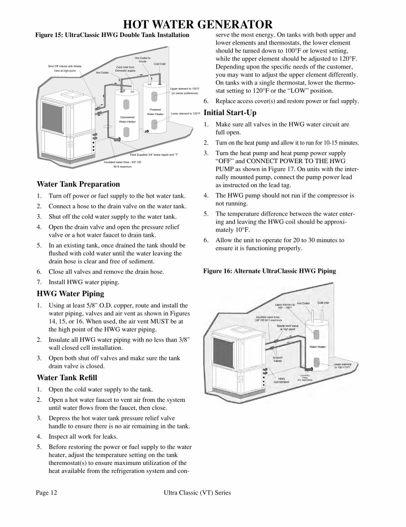
Typically a single tank of at least 52 gallons is used to limit installation costs and space. However, a dual tank, as shown in Figure 15, is the most efficient system providing the maximum storage and temperate source water to the desuperheater. Using a concentric hot water tank connection fitting eliminates the need to tie into the hot water tank water piping. In high liming areas (hardness>100ppm or 6 grains per gallon) the alternative piping scheme in Figure 16 may be used to eliminate the
possible scaling of the smaller cross-sectioned area of the concentric fitting. It is always advisable to use water softening equipment on domestic well water systems to reduce the liming potential and lengthen equipment life. In extreme water conditions, it may be wise to not use the HWG option since the probable cost of frequent maintenance may offset or exceed any savings.
InstallationThe HWG aquastat is set at 125 °F and is located on the HWG heat exchanger “Water In” line. If the HWG is connected incorrectly or if circulation is reversed, the aquastat will sense leaving water temperature and prevent HWG operation. UNDER NO CIRCUMSTANCES DISCONNECT OR REMOVE THE HWG AQUASTAT! Full load conditions could drive hot water tank temperatures far above desirable temperature levels if the aquastat has been disconnected or removed.
The heat pump, water piping, pump, and hot water tank should be located where the ambient temperature does not fall below 50 °F. Keep water piping lengths at a minimum – DO NOT use a one way length greater than 50 feet. All installations must be made in accordance with local codes. The installer is responsible for knowing the local requirements, and for performing the installation accordingly.
Figure 14: Typical UltraClassic HWG Installation
Page 12 Ultra Classic (VT) Series
Water Tank Preparation1. Turn off power or fuel supply to the hot water tank.
2. Connect a hose to the drain valve on the water tank.
3. Shut off the cold water supply to the water tank.
4. Open the drain valve and open the pressure relief valve or a hot water faucet to drain tank.
5. In an existing tank, once drained the tank should be flushed with cold water until the water leaving the drain hose is clear and free of sediment.
6. Close all valves and remove the drain hose.
7. Install HWG water piping.
HWG Water Piping1. Using at least 5/8" O.D. copper, route and install the
water piping, valves and air vent as shown in Figures 14, 15, or 16. When used, the air vent MUST be at the high point of the HWG water piping.
2. Insulate all HWG water piping with no less than 3/8" wall closed cell installation.
3. Open both shut off valves and make sure the tank drain valve is closed.
Water Tank Refill1. Open the cold water supply to the tank.
2. Open a hot water faucet to vent air from the system until water flows from the faucet, then close.
3. Depress the hot water tank pressure relief valve handle to ensure there is no air remaining in the tank.
4. Inspect all work for leaks.
5. Before restoring the power or fuel supply to the water heater, adjust the temperature setting on the tank theremostat(s) to ensure maximum utilization of the heat available from the refrigeration system and con-
serve the most energy. On tanks with both upper and lower elements and thermostats, the lower element should be turned down to 100°F or lowest setting, while the upper element should be adjusted to 120°F. Depending upon the specific needs of the customer, you may want to adjust the upper element differently. On tanks with a single thermostat, lower the thermo-stat setting to 120°F or the “LOW” position.
6. Replace access cover(s) and restore power or fuel supply.
Initial Start-Up1. Make sure all valves in the HWG water circuit are
full open.
2. Turn on the heat pump and allow it to run for 10-15 minutes.
3. Turn the heat pump and heat pump power supply “OFF” and CONNECT POWER TO THE HWG PUMP as shown in Figure 17. On units with the inter-nally mounted pump, connect the pump power lead as instructed on the lead tag.
4. The HWG pump should not run if the compressor is not running.
5. The temperature difference between the water enter-ing and leaving the HWG coil should be approxi-mately 10°F.
6. Allow the unit to operate for 20 to 30 minutes to ensure it is functioning properly.
Shut Off Valves with Waste
Vent at high point
Insulated water lines - 5/8” OD
50 ft maximum
Upper element to 130°F
(or owner preference)
Cold Inlet
Hot Outlet tohouse
Powered
Water Heater
Cold Inlet fromDomestic supply
Hot Outlet
Unpowered
Water Heater
Field Supplied 3/4” brass nipple and “T”
Lower element to 120°F
Figure 15: UltraClassic HWG Double Tank Installation
Figure 16: Alternate UltraClassic HWG Piping
HOT WATER GENERATOR
Ultra Classic (VT) Series Page 13
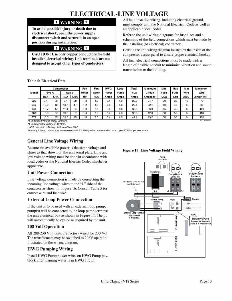
ELECTRICAL-LINE VOLTAGEAll field installed wiring, including electrical ground, must comply with the National Electrical Code as well as all applicable local codes.
Refer to the unit wiring diagrams for fuse sizes and a schematic of the field connections which must be made by the installing (or electrical) contractor.
Consult the unit wiring diagram located on the inside of the compressor access panel to ensure proper electrical hookup.
All final electrical connections must be made with a length of flexible conduit to minimize vibration and sound transmission to the building.
To avoid possible injury or death due to electrical shock, open the power supply disconnect switch and secure it in an open position during installation.
CAUTION: Use only copper conductors for field installed electrical wiring. Unit terminals are not designed to accept other types of conductors.
Figure 17: Line Voltage Field Wiring
Table 5: Electrical Data
General Line Voltage WiringBe sure the available power is the same voltage and phase as that shown on the unit serial plate. Line and low voltage wiring must be done in accordance with local codes or the National Electric Code, whichever is applicable.
Unit Power Connection Line voltage connection is made by connecting the incoming line voltage wires to the “L” side of the contactor as shown in Figure 16. Consult Table 5 for correct wire and fuse size.
External Loop Power ConnectionIf the unit is to be used with an external loop pump, the pump(s) will be connected to the loop pump terminals in the unit electrical box as shown in Figure 17. The pumps will automatically be cycled as required by the unit.
208 Volt OperationAll 208-230 Volt units are factory wired for 230 Volt. The transformers may be switched to 208V operation as illustrated on the wiring diagram.
HWG Pumping WiringInstall HWG Pump power wires on HWG Pump power block after insuring water is in HWG circuit.
�������������
��� ��� ��� ���� ����� ������� ��� ��� ��� �������
����� ����� ����� ���� ���� ��� ������� ���� ���� ���� ����
��� ��� ��� ��� �� ��� ���� ���� ���� �������� ��� ��� ��� ������������
��� ��� �� ��� �� ��� ��� ��� ��� ���� ���� �� �� �� ��
��� ���� �� ���� �� ��� ��� ��� ��� ���� ���� �� �� � ��
��� ���� �� ���� �� ��� ��� ��� ��� ���� ���� �� �� � ���
��� ���� �� ���� �� ��� ��� ��� ��� ���� ���� �� �� � ���
��� ���� �� ���� �� ��� ��� ��� ��� ���� ���� �� �� � ����������������������������������������������������������
������������������������������������������������������������������������������������������������������������������������������������������������������������������������������°��������������������
�������� ���������������������������� ��������������������������������������������������������������������������������������� �������
����������
����� �����
TransformerCompressor A
Contactor
L1L2
208-230/60/1 4 Amp Max.
Source Pump Ground
PR
ICM2 Controller
Pump Circt Brkr
with ground(see Elect. Table for wire
and Brkr. size)
Compressor BContactor
CX
M C
on
trol - A
Low V
oltageC
onnector
CX
M C
on
trol - B
Low V
oltageC
onnector
HWG
Install HWG Pump Power after insuring
water is in HWG circuit
Yellow
Blk
External Loop Pump(s)
WARNING
WARNING
Page 14 Ultra Classic (VT) Series
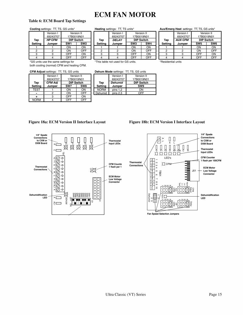
ECM FAN MOTOR“fine tune” airflow adjustments. The TEST setting runstheECMmotorat70%torque,whichcausesthemotortooperatelikeastandardPSCmotor,anddisablestheCFMcounter.
Dehumidification Modesettings:Thedehumidification mode setting provides field selectionofhumiditycontrol.Whenoperatinginthe normal mode, the cooling airflow settings are determinedbythecoolingtapsettingabove.Whendehumidification is enabled there is a reduction in airflow in cooling to increase the moisture removal oftheheatpump.Consultsubmittaldataorspecifications catalog for the specific unit series and model to correlate speed tap to airflow in CFM. The dehumidification mode can be enabled in two ways. 1. Constant Dehumidification Mode:Whenthe
dehumidification mode is selected (via DIP switch or jumper setting), the ECM motor will operatewithamultiplierappliedtothecoolingCFM settings (approx. 20-25% lower airflow). Anytimetheunitisrunninginthecoolingmode,it will operate at the lower airflow to improve latentcapacity.The“DEHUM”LEDwillbeilluminated at all times. Heating airflow is not affected. NOTE: Do not select dehumidification modeifcoolingsettingistap1.
2. Automatic(Humidistat-controlled)Dehumidification Mode:Whenthedehumidification mode is selected (via DIP switch or jumper setting) AND a humidistat isconnectedtoterminalDH(versionII)orHUM (version I), the cooling airflow will only bereducedwhenthehumidistatsensesthatadditional dehumidification is required. The DH (orHUM)terminalisreverselogic.Therefore,ahumidistat(notdehumidistat)isrequired.The“DEHUM”LEDwillbeilluminatedonlywhenthehumidistat is calling for dehumidification mode. Heating airflow is not affected. NOTE: Do not select dehumidification mode if cooling setting is tap1.
Fan speeds are selected with jumpers for version IorviaaninepositionDIPswitchforversionII.TotakefulladvantageoftheECMmotorfeatures,amulti-stagethermostatshouldbeused(2-stageheat/2-stagecoolor3-stageheat/2-stagecool).
Note:PowermustbeofftotheunitforatleastthreesecondsbeforetheECMmotorwillrecognizeaspeedchange.Themotorwillrecognizeachangein the CFM Adjust or dehumidification mode settingswhiletheunitispowered.
There are four different airflow settings from lowest airflow rate (speed tap 1) to the highest airflow rate (speedtap4).ThechartsbelowindicatesettingsforbothversionsoftheECMinterfaceboard,followedbydetailedinformationforeachsetting.
Coolingsettings:Thecoolingsettingdeterminesthecooling(normal)CFMforallunitswithECMmotor.Cooling(normal)settingisusedwhentheunit is not in dehumidification mode. This setting alsodeterminestheheatingCFMforGenesis(GS)units.Tap1isthelowestCFMsetting,whiletap4isthehighestCFMsetting.Toavoidaircoilfreeze-up,tap 1 may not be used if the dehumidification mode is selected. Consult submittal data or specifications catalog for the specific unit series and model to correlate speed tap setting to airflow in CFM.
Heatingsettings:TheheatingsettingdeterminestheheatingCFMforTranquility27™(TT)andTranquility20™(TS)units.ThissettingisnotusedforGenesis(GS)units.Tap1isthelowestCFMsetting,whiletap4isthehighestCFMsetting.Consult submittal data or specifications catalog for the specific unit series and model to correlate speed tap setting to airflow in CFM.
Auxiliary/EmergencyHeatsettings:Theauxiliary/emergencyheatsettingdeterminestheCFMwhentheunitisinauxiliaryheatoremergencyheatmode.Thissettingisusedforresidentialunitswithinternalelectricheat.Whenauxiliaryelectricheatisenergized(i.e.compressorandelectricheat),thegreateroftheauxiliary/emergencyorheatingsettingwillbeused.A“G”(fan)signalmustbepresentfromthethermostatforelectricheattooperate.Consultthe submittal data or specifications catalog for the specific unit series and model to correlate speed tap setting to airflow in CFM.
CFMAdjustsettings: The CFM adjust setting allowsfourselections.TheNORMsettingisthefactory default position. The + or – settings adjust the airflow by +/- 15%. The +/- settings are used to
Ultra Classic (VT) Series Page 15
Coolingsettings:TT,TS,GSunits* Heatingsettings:TT,TSunits* Aux/EmergHeat settings:TT,TS,GSunits*VersionI VersionI VersionI69243707 69243707 69243707
Tap HP CFM Tap DELAY Tap AUX CFMSetting Jumper SW1 SW2 Setting Jumper SW3 SW4 Setting Jumper SW5 SW6
1 1 ON ON 1 1 ON ON 1 1 ON ON2 2 ON OFF 2 2 ON OFF 2 2 ON OFF3 3 OFF ON 3 3 OFF ON 3 3 OFF ON4 4 OFF OFF 4 4 OFF OFF 4 4 OFF OFF
*GSunitsusethesamesettingsfor *ThistablenotusedforGSunits. *Residentialunitsbothcooling(normal)CFMandheatingCFM.
CFMAdjustsettings:TT,TS,GSunits DehumModesettings:TT,TS,GSunitsVersionI VersionI69243707 69243707
Tap CFM Adj Tap DehumidSetting Jumper SW7 SW8 Setting JumperTEST 1 ON ON NORM pins1,2
- 2 ON OFF Dehumid pins2,3+ 3 OFF ON
NORM 4 OFF OFF
VersionII17B0019N01DIPSwitch
VersionII
VersionII17B0019N01
VersionII17B0019N01
DIPSwitch DIPSwitch
ONOFF
DIPSwitch
VersionII17B0019N01DIPSwitch
17B0019N01
SW9
Table 6: ECM Board Tap Settings
Y
G G G G R
WOY2Y1GRC
Y2Y1
GO
WC
RDH
AL1A
AAL1
SW1
SW2
SW3
SW4
SW5
SW6
SW7
SW8
SW9O
FFO
N
G
DEHUM
CFM
TB1
J1S1
ThermostatInputLEDs
CFMCounter1flashper100CFM
ECMMotorLowVoltageConnector
1/4"SpadeConnections
toCXMorDXMBoard
ThermostatConnections
DehumidificationLED
FanSpeedSelectionDIPSwitch
J01
AL
AL
A
G Y1 Y2 O W1 EM C R
GY1
Y2O
W1
EMN
CC
RH
um
32
14
321 433 2122
1
4 321 4
56
78
910
L
LED's
TB01
CFM
Dehum
id
Norm
Norm
Test(–)(+)
CFM
Adjust
AuxC
FMH
PC
FM
Delay
1/4"SpadeConnectionstoCXMorDXMBoard
ThermostatInputLEDs
CFMCounter1flashper100CFM
ECMMotorLowVoltageConnector
DehumidificationLED
FanSpeedSelectionJumpers
ThermostatConnections
Figure 18a: ECM Version II Interface Layout Figure 18b: ECM Version I Interface Layout
ECM FAN MOTOR
Page 16 Ultra Classic (VT) Series
Figure 19: Low Voltage Field Wiring
TransformerCompressor A
Contactor
L1L2
208-230/60/1 4 Amp Max.
Source Pump Ground
PR
ICM2 Controller
Pump Circt Brkr
with ground(see Elect. Table for wire
and Brkr. size)
Compressor BContactor
CX
M C
on
trol - A
Low V
oltageC
onnector
CX
M C
on
trol - B
Low V
oltageC
onnector
HWG
Install HWG Pump Power after insuring
water is in HWG circuit
Yellow
Blk
External Loop Pump(s)
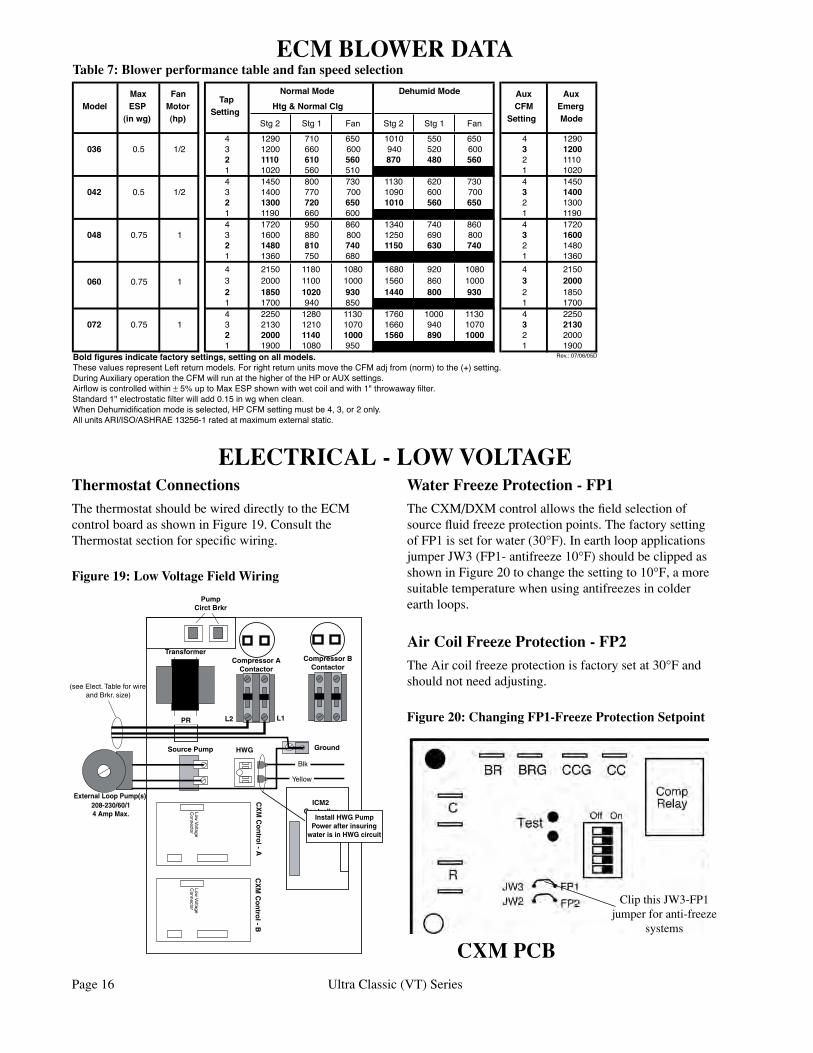
Thermostat ConnectionsThe thermostat should be wired directly to the ECM control board as shown in Figure 19. Consult the Thermostat section for specific wiring.
Water Freeze Protection - FP1The CXM/DXM control allows the field selection of source fluid freeze protection points. The factory setting of FP1 is set for water (30°F). In earth loop applications jumper JW3 (FP1- antifreeze 10°F) should be clipped as shown in Figure 20 to change the setting to 10°F, a more suitable temperature when using antifreezes in colder earth loops.
Air Coil Freeze Protection - FP2The Air coil freeze protection is factory set at 30°F and should not need adjusting.
Figure 20: Changing FP1-Freeze Protection Setpoint
CXM PCB
Clip this JW3-FP1 jumper for anti-freeze
systems
ELECTRICAL - LOW VOLTAGE
Table 7: Blower performance table and fan speed selection
VTBlowerPerformance
Max Fan NormalMode DehumidMode Aux AuxModel ESP Motor
TapHtg&NormalClg CFM Emerg
(inwg) (hp)Setting
Stg2 Stg1 Fan Stg2 Stg1 Fan Setting Mode
4 1290 710 650 1010 550 650 4 1290036 0.5 1/2 3 1200 660 600 940 520 600 3 1200
2 1110 610 560 870 480 560 2 11101 1020 560 510 1 10204 1450 800 730 1130 620 730 4 1450
042 0.5 1/2 3 1400 770 700 1090 600 700 3 14002 1300 720 650 1010 560 650 2 13001 1190 660 600 1 11904 1720 950 860 1340 740 860 4 1720
048 0.75 1 3 1600 880 800 1250 690 800 3 16002 1480 810 740 1150 630 740 2 14801 1360 750 680 1 13604 2150 1180 1080 1680 920 1080 4 2150
060 0.75 1 3 2000 1100 1000 1560 860 1000 3 20002 1850 1020 930 1440 800 930 2 18501 1700 940 850 1 17004 2250 1280 1130 1760 1000 1130 4 2250
072 0.75 1 3 2130 1210 1070 1660 940 1070 3 21302 2000 1140 1000 1560 890 1000 2 20001 1900 1080 950 1 1900
Rev.:07/06/05DBoldfiguresindicatefactorysettings,settingonallmodels.These values represent Left return models. For right return units move the CFM adj from (norm) to the (+) setting.DuringAuxiliaryoperationtheCFMwillrunatthehigheroftheHPorAUXsettings.Airflowiscontrolledwithin±5%uptoMaxESPshownwithwetcoilandwith1"throwawayfilter.Standard1"electrostaticfilterwilladd0.15inwgwhenclean.WhenDehumidificationmodeisselected,HPCFMsettingmustbe4,3,or2only.AllunitsARI/ISO/ASHRAE13256-1ratedatmaximumexternalstatic.
Revision DateDatafromTomNorth9/00 10/31/04 RRBNewdatafromT North added right return note adj. 072 numbers 3/31/05 RRBChanged042w/AuxHeattomatchnormal2ndstagefromTNorth 5/12/05 RRB
ECM BLOWER DATA
Ultra Classic (VT) Series Page 17
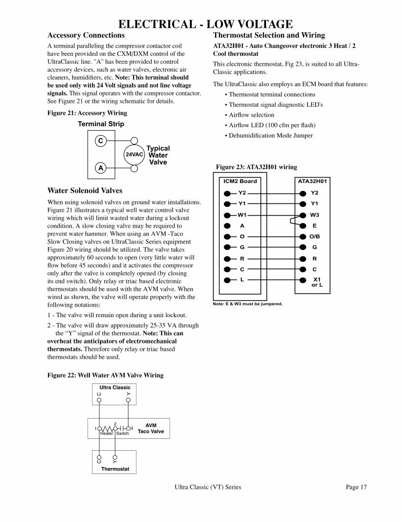
Accessory ConnectionsA terminal paralleling the compressor contactor coil have been provided on the CXM/DXM control of the UltraClassic line. "A" has been provided to control accessory devices, such as water valves, electronic air cleaners, humidifiers, etc. Note: This terminal should be used only with 24 Volt signals and not line voltage signals. This signal operates with the compressor contactor. See Figure 21 or the wiring schematic for details.
Figure 21: Accessory Wiring
Figure 22: Well Water AVM Valve Wiring
��������������
�����������������
�
�
�����
Water Solenoid Valves When using solenoid valves on ground water installations. Figure 21 illustrates a typical well water control valve wiring which will limit wasted water during a lockout condition. A slow closing valve may be required to prevent water hammer. When using an AVM -Taco Slow Closing valves on UltraClassic Series equipment Figure 20 wiring should be utilized. The valve takes approximately 60 seconds to open (very little water will flow before 45 seconds) and it activates the compressor only after the valve is completely opened (by closing its end switch). Only relay or triac based electronic thermostats should be used with the AVM valve. When wired as shown, the valve will operate properly with the following notations:
1 - The valve will remain open during a unit lockout.
2 - The valve will draw approximately 25-35 VA through the “Y” signal of the thermostat. Note: This can overheat the anticipators of electromechanical thermostats. Therefore only relay or triac based thermostats should be used.
C
UltraClassic
C
Thermostat
Y
12
3
Y
AVMTacoValveHeater Switch
Thermostat Selection and WiringATA32H01 - Auto Changeover electronic 3 Heat / 2 Cool thermostat
This electronic thermostat, Fig 23, is suited to all Ultra-Classic applications.
The UltraClassic also employs an ECM board that features:
• Thermostat terminal connections
• Thermostat signal diagnostic LED's
• Airflow selection
• Airflow LED (100 cfm per flash)
• Dehumidification Mode Jumper
Figure 23: ATA32H01 wiring
ELECTRICAL - LOW VOLTAGE
������������������������������
�� ��
���
�
�
������
�
��
�
��
�
�
�
�
�
��
�
��
���������� ��������
Page 18 Ultra Classic (VT) Series
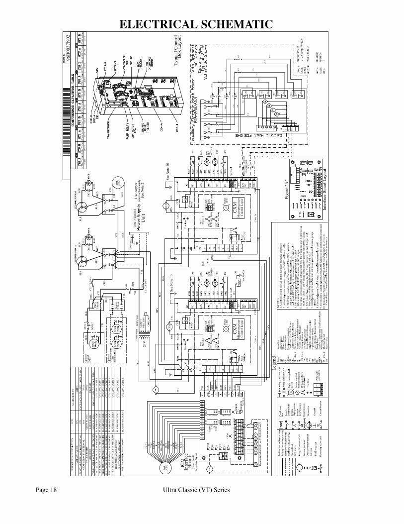
ELECTRICAL SCHEMATIC
Ultra Classic (VT) Series Page 19
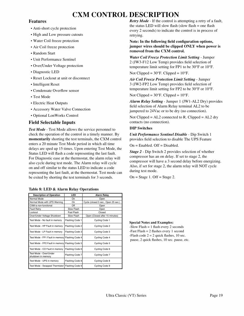
DescriptionofOperation LED AlarmRelayNormalMode On OpenNormalModewithUPSWarning On Cycle(closed5sec.,Open25sec.)CXMisnon-functional Off OpenFaultRetry SlowFlash OpenLockout FastFlash ClosedOver/UnderVoltageShutdown SlowFlash Open(Closedafter15minutes)
TestMode-Nofaultinmemory FlashingCode1 CyclingCode1
TestMode-HPFaultinmemory FlashingCode2 CyclingCode2
TestMode-LPFaultinmemory FlashingCode3 CyclingCode3
TestMode-FP1Faultinmemory FlashingCode4 CyclingCode4
TestMode-FP2Faultinmemory FlashingCode5 CyclingCode5
TestMode-COFaultinmemory FlashingCode6 CyclingCode6
TestMode-Over/Undershutdowninmemory FlashingCode7 CyclingCode7
TestMode-UPSinmemory FlashingCode8 CyclingCode8
TestMode-SwappedThermistor FlashingCode9 CyclingCode9
Features • Anti-short cycle protection
• High and Low pressure cutouts
• Water Coil freeze protection
• Air Coil freeze protection
• Random Start
• Unit Performance Sentinel
• Over/Under Voltage protection
• Diagnostic LED
• Reset Lockout at unit or disconnect
• Intelligent Reset
• Condensate Overflow sensor
• Test Mode
• Electric Heat Outputs
• Accessory Water Valve Connection
• Optional LonWorks Control
Field Selectable InputsTest Mode - Test Mode allows the service personnel to check the operation of the control in a timely manner. By momentarily shorting the test terminals, the CXM control enters a 20 minute Test Mode period in which all time delays are sped up 15 times. Upon entering Test Mode, the Status LED will flash a code representing the last fault. For Diagnostic ease at the thermostat, the alarm relay will also cycle during test mode. The Alarm relay will cycle on and off similar to the status LED to indicate a code representing the last fault, at the thermostat. Test mode can be exited by shorting the test terminals for 3 seconds.
CXM CONTROL DESCRIPTIONRetry Mode - If the control is attempting a retry of a fault, the status LED will slow flash (slow flash = one flash every 2 seconds) to indicate the control is in process of retrying.
Note: In the following field configuration options, jumper wires should be clipped ONLY when power is removed from the CXM control.
Water Coil Freeze Protection Limit Setting - Jumper 2 (JW3-F12 Low Temp) provides field selection of temperature limit setting for FP1 to be 30°F or 10°F.
Not Clipped = 30°F. Clipped = 10°F.
Air Coil Freeze Protection Limit Setting - Jumper 3 (JW2-FP2 Low Temp) provides field selection of temperature limit setting for FP2 to be 30°F or 10°F.
Not Clipped = 30°F. Clipped = 10°F.
Alarm Relay Setting - Jumper 1 (JW1-AL2 Dry) provides field selection of Alarm Relay terminal AL2 to be jumpered to 24Vac or to be dry (no connection).
Not Clipped = AL2 connected to R. Clipped = AL2 dry contacts (no connection).
DIP Switches
Unit Performance Sentinel Disable - Dip Switch 1 provides field selection to disable The UPS Feature
On = Enabled. Off = Disabled.
Stage 2 - Dip Switch 2 provides selection of whether compressor has an on delay. If set to stage 2, the compressor will have a 3 second delay before energizing. Also, if set for stage 2, the alarm relay will NOT cycle during test mode.
On = Stage 1. Off = Stage 2.
Table 8: LED & Alarm Relay Operations
Special Notes and Examples:-Slow Flash = 1 flash every 2 seconds-Fast Flash = 2 flashes every 1 second-Flash code 2 = 2 quick flashes, 10 sec. pause, 2 quick flashes, 10 sec. pause, etc.
Page 20 Ultra Classic (VT) Series
Safety FeaturesThe following safety features are provided to protect the compressor, heat exchangers, wiring and other components from damage caused by operation outside of design conditions.
Anti-Short Cycle Protection- The control features a 5 minute anti-short cycle protection for the compressor. Note: The 5 minute anti-short cycle also occurs at power up.
Random Start - The control features a random start upon power up of from 5-80 seconds. Fault Retry - In Fault Retry mode, the Status LED begins slow flashing to signal that the control is trying to recover from a fault input. The CXM control will stage off the outputs and then “try again” to satisfy the thermostat "Y" input call. Once the thermostat input calls are satisfied, the control will continue on as if no fault occured. If 3 consecutive faults occur without satisfying the thermostat "Y" input call, then the control will go to Lockout mode. The last fault causing the lockout will be stored in memory and can be viewed by going into test mode.
Lockout - In Lockout mode, the Status LED will begin fast flashing. The compressor relay is turned off immediately. Lockout mode can be soft reset via the thermostat “Y” input or can be hard reset via the disconnect. The last fault causing the lockout will be stored in memory and can be viewed by going into test mode.
Lockout with Emergency Heat - While in Lockout mode, if W becomes active, then Emergency Heat mode will occur.
High Pressure Switch - When the High Pressure Switch opens due to high refrigerant pressures, the Compressor relay is de-energized immediately since the High Pressure Switch is in series with the compressor contactor coil. The High Pressure Fault recognition is immediate as well. High Pressure Lockout Code = 2Example: 2 quick flashes, 10 sec pause, 2 quick flashes, 10 sec. pause, etc.
Low Pressure Switch - The Low Pressure Switch must be open and remain open for 30 continuous seconds during "on" cycle to be recognized as a Low Pressure fault. If the low pressure switch is open for 30 seconds prior to compressor power up it will be considered a low pressure (loss of charge) fault. The Low Pressure Switch input is bypassed for the initial 60 seconds of a compressor run cycle. Low Pressure Lockout Code = 3. thermistor temperature must be below the selected freeze
protection limit setting for 30 continuous seconds during a compressor run cycle to be recognized as a FP1 fault. The FP1 input is bypassed for the initial 60 seconds of a compressor run cycle. FP1 Lockout Code = 4.
Air Coil Freeze Protection (FP2) - The FP2 thermistor temperature must be below the selected freeze protection limit setting for 30 continuous seconds during a compressor run cycle to be recognized as a FP2 fault. The FP2 input is bypassed for the initial 60 seconds of a compressor run cycle. FP2 Lockout Code = 5.
Condensate Overflow - The Condensate Overflow sensor must sense overflow levels for 30 continuous seconds to be recognized as a CO fault. Condensate Overflow will be monitored at all times. CO Lockout Code = 6.
Over/Under Voltage Shutdown - An Over/Under Voltage condition exists when the control voltage is outside the range of 19Vac to 30Vac. Over/Under Voltage Shutdown is self resetting in that if the voltage comes back within range of 19Vac to 30Vac for at least 0.5 seconds, then normal operation is restored. This is not considered a fault or lockout. If the CXM is in over/under voltage shutdown for 15 minutes, the alarm relay will close. Over/Under Voltage Shutdown Code = 7.
Unit Performance Sentinel-UPS (patent pending) - The UPS feature warns when the heat pump is operating inefficiently. A UPS condition exists when:
a) in heating mode with compressor energized, if FP2 is greater than 125°F for 30 continuous seconds,
or b) in cooling mode with compressor energized, if FP1 is greater than 125°F for 30 continuous seconds, or FP2 is less than 40°F for 30 continuous seconds.
If a UPS condition occurs, the control will immediately go to UPS warning. The status LED will remain on as if the control is on Normal mode. (see"LED and Alarm Relay Operation Table" ). Outputs of the control, excluding LED and Alarm Relay, will NOT be affected by UPS. The UPS condition cannot occur during a compressor off cycle. During UPS warning, the alarm relay will cycle on and off. The cycle rate will be On for 5 seconds, Off for 25 seconds, On for 5 seconds, Off for 25 seconds, etc. Unit Performance Sentinel Warning Code = 8.
CXM CONTROL DESCRIPTIONWater Coil Freeze Protection (FP1) - The FP1
Ultra Classic (VT) Series Page 21
Diagnostic FeaturesThe Status LED on the CXM control advises the serviceman of the current status of the CXM control. The status LED can display either the current CXM mode or the last fault memory if in test mode. See Table 8 for a complete listing of codes.
Unit Operation DescriptionPowerUp - The unit will not operate until all the inputs and safety controls are checked for normal conditions. Note: The compressor will have a 5 minute anti-short cycle delay at power-up.
Standby - In Standby mode, Y and W inputs are not active. Inputs O and G may be active. Compressor will be off.
Cooling - To enter Cooling mode, Y and O become active. The first time after power-up that there is a call for compressor, the compressor will follow a 5 to 80 second random start delay. There will also be a 5 min compressor anti-short cycle protection time as well. After the random start delay, the compressor relay is energized. On all subsequent compressor calls, the random start delay is omitted.
Heating Stage 1 - To enter Heating Stage 1 mode, Y becomes active. The first time after power-up that there is a call for compressor, the compressor will follow a 5 to 80 second random start delay. There will also be a 5 min compressor anti-short cycle protection time as well. After the random start delay, the compressor relay is energized. On all subsequent compressor calls, the random start delay is omitted.
Heating Stage 2 - To enter Heating Stage 2 mode, W becomes active (Y already active). The Compressor relay remains on. EH1 is turned on immediately. With continuing Heating Stage 2 demand, EH2 will turn on after 10 minutes. The EH2 will not turn on in heating (or will turn off if already on) if loop temperature is above approximately 50°F (FP1 >45°F).
Emergency Heat - In Emergency Heat mode, W becomes active while Y is not active. EH1 is turned on immediately. With continuing Emergency Heat demand, EH2 will turn on after 5 minutes. The FP1 and FP2 temperatures do not effect emergency heat operation.
ECM Control Board The UltraClassic also employs an ECM board that features: • Thermostat terminal connections
• Thermostat signal diagnostic LED's
• Airflow selection
• Airflow LED (100 cfm per flash)
• Dehumidification Mode Jumper
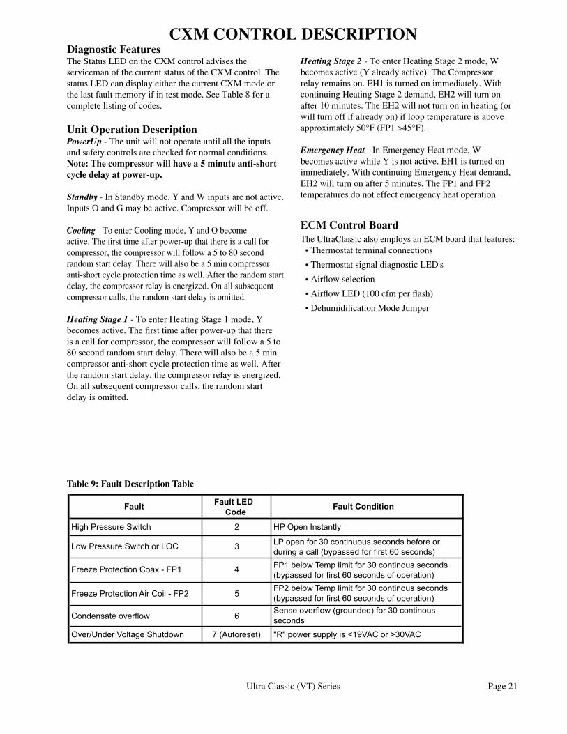
Table 9: Fault Description Table
����� �������������
���������������
�������������������� � �����������������
�������������������������� � ����������������������������������������������������������������������������������������
���������������������������� � �����������������������������������������������������������������������������������������
�������������������������������� ������������������������������������������������������������������������������������������
������������������� ��������������������������������������������������
��������������������������� ������������� ������������������������������������
CXM CONTROL DESCRIPTION
Page 22 Ultra Classic (VT) Series
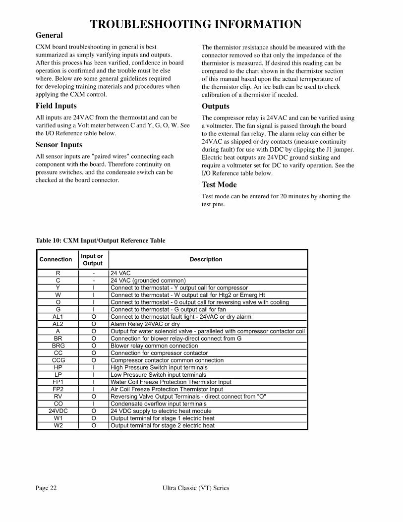
TROUBLESHOOTING INFORMATIONGeneralCXM board troubleshooting in general is best summarized as simply varifying inputs and outputs. After this process has been varified, confidence in board operation is confirmed and the trouble must be else where. Below are some general guidelines required for developing training materials and procedures when applying the CXM control.
Field InputsAll inputs are 24VAC from the thermostat.and can be varified using a Volt meter between C and Y, G, O, W. See the I/O Reference table below.
Sensor InputsAll sensor inputs are "paired wires" connecting each component with the board. Therefore continuity on pressure switches, and the condensate switch can be checked at the board connector.
The thermistor resistance should be measured with the connector removed so that only the impedance of the thermistor is measured. If desired this reading can be compared to the chart shown in the thermistor section of this manual based upon the actual termperature of the thermistor clip. An ice bath can be used to check calibration of a thermistor if needed.
OutputsThe compressor relay is 24VAC and can be varified using a voltmeter. The fan signal is passed through the board to the external fan relay. The alarm relay can either be 24VAC as shipped or dry contacts (measure continuity during fault) for use with DDC by clipping the J1 jumper. Electric heat outputs are 24VDC ground sinking and require a voltmeter set for DC to varify operation. See the I/O Reference table below.
Test ModeTest mode can be entered for 20 minutes by shorting the test pins.
���������� ��������������
�����������
� � ������� � ������������������������� � ����������������������������������������������������� � ����������������������������������������������������������� � ����������������������������������������������������������������������� � ���������������������������������������������
��� � ��������������������������������������������������������� � ������������������������� � ����������������������������������������������������������������������������� � ���������������������������������������������������� � �������������������������������� � �������������������������������������� � ���������������������������������������� � �������������������������������������� � �������������������������������������� � ������������������������������������������������ � ��������������������������������������������� � ������������������������������������������������������������ � �����������������������������������
����� � ��������������������������������������� � ������������������������������������������� � �����������������������������������������
Table 10: CXM Input/Output Reference Table
Ultra Classic (VT) Series Page 23
See“DoesnotOperate
inClg”
See“OnlyCompRuns”
Start
DidUnitAttemptto
Start?
DidUnitLockoutatStart-up?
UnitShortCycles?
OnlyFanRuns?
OnlyCompressor
Runs?
Didunitlockoutafteraperiodof
operation?
Doesunitoperateincooling?
Unit is OK!‘See Performance
Troubleshooting’ for further help
CheckMainpower(seepower
problems)
CheckfaultLEDcodeoncontrolboard
Yes
No
No
No
No
No
Yes
No
Yes
SeeHPFault
SeeLP/LOC
Fault
SeeFP1Fault
SeeFP2Fault
SeeCondensate
Fault
SeeOver/Under
Voltage
Nofaultshown
ReplaceCXM
See“Unitshort
cycles”
See“OnlyFanRuns”
No
Yes
Yes
Yes
Yes
CXM Functional Troubleshooting Chart
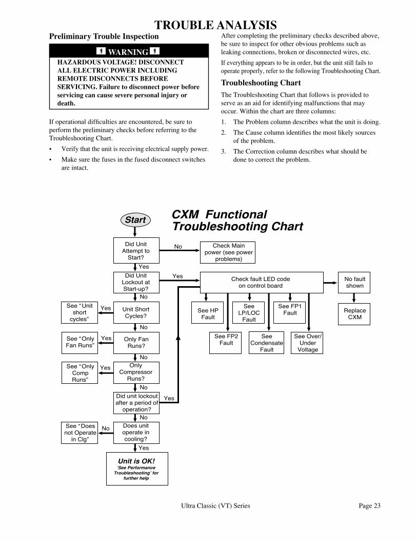
Preliminary Trouble Inspection
HAZARDOUS VOLTAGE! DISCONNECT ALL ELECTRIC POWER INCLUDING REMOTE DISCONNECTS BEFORE SERVICING. Failure to disconnect power before servicing can cause severe personal injury or death.
TROUBLE ANALYSIS
If operational difficulties are encountered, be sure to perform the preliminary checks before referring to the Troubleshooting Chart.
• Verify that the unit is receiving electrical supply power.
• Make sure the fuses in the fused disconnect switches are intact.
After completing the preliminary checks described above, be sure to inspect for other obvious problems such as leaking connections, broken or disconnected wires, etc.
If everything appears to be in order, but the unit still fails to operate properly, refer to the following Troubleshooting Chart.
Troubleshooting ChartThe Troubleshooting Chart that follows is provided to serve as an aid for identifying malfunctions that may occur. Within the chart are three columns:
1. The Problem column describes what the unit is doing.
2. The Cause column identifies the most likely sources of the problem.
3. The Correction column describes what should be done to correct the problem.
WARNING
Page 24 Ultra Classic (VT) Series
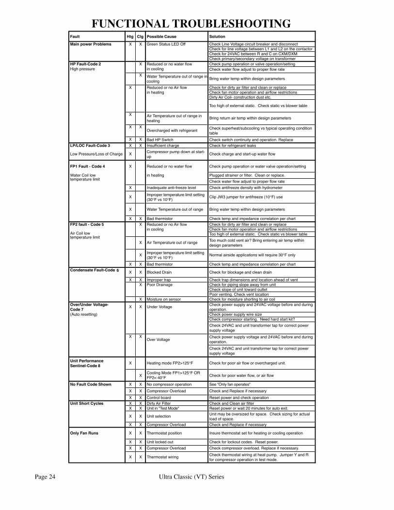
FUNCTIONAL TROUBLESHOOTINGFault Htg Clg PossibleCause Solution
MainpowerProblems X X GreenStatusLEDOff CheckLineVoltagecircuitbreakeranddisconnectCheckforlinevoltagebetweenL1andL2onthecontactorCheckfor24VACbetweenRandConCXM/DXMCheckprimary/secondaryvoltageontransformer
HPFault-Code2 X Reducedornowaterflow Checkpumpoperationorvalveoperation/settingHighpressure incooling Check water flow adjust to proper flow rate
X WaterTemperatureoutofrangeincooling Bringwatertempwithindesignparameters
X ReducedornoAirflow Checkfordirtyairfilterandcleanorreplaceinheating Checkfanmotoroperationandairflowrestrictions
DirtyAirCoil-constructiondustetc.
Toohighofexternalstatic.Checkstaticvsblowertable
X AirTemperatureoutofrangeinheating Bringreturnairtempwithindesignparameters
X XOverchargedwithrefrigerant Checksuperheat/subcoolingvstypicaloperatingcondition
tableX X BadHPSwitch Checkswitchcontinuityandoperation.Replace
LP/LOCFault-Code3 X X Insufficientcharge Checkforrefrigerantleaks
LowPressure/LossofCharge X Compressorpumpdownatstart-up Checkchargeandstart-upwaterflow
FP1Fault-Code4 X Reducedornowaterflow Checkpumpoperationorwatervalveoperation/setting
WaterCoillowtemperaturelimit
inheating Pluggedstrainerorfilter.Cleanorreplace.Check water flow adjust to proper flow rate
X Inadequateanti-freezelevel Checkantifreezedensitywithhydrometer
X Impropertemperaturelimitsetting(30°Fvs10°F) Clip JW3 jumper for antifreeze (10°F)use
X WaterTemperatureoutofrange Bringwatertempwithindesignparameters
X X Badthermistor ChecktempandimpedancecorrelationperchartFP2fault-Code5 X ReducedornoAirflow Checkfordirtyairfilterandcleanorreplace
AirCoillowtemperaturelimit
incooling CheckfanmotoroperationandairflowrestrictionsToohighofexternalstatic.Checkstaticvsblowertable
X AirTemperatureoutofrange Toomuchcoldventair?Bringenteringairtempwithindesignparameters
X Impropertemperaturelimitsetting(30°Fvs10°F) Normalairsideapplicationswillrequire30°Fonly
X X Badthermistor ChecktempandimpedancecorrelationperchartCondensateFault-Code 6 X X BlockedDrain Checkforblockageandcleandrain
X X Impropertrap ChecktrapdimensionsandlocationaheadofventX PoorDrainage Checkforpipingslopeawayfromunit
CheckslopeofunittowardoutletPoorventing.Checkventlocation
X Moistureonsensor CheckformoistureshortingtoaircoilOver/UnderVoltage-Code7 X X UnderVoltage Checkpowersupplyand24VACvoltagebeforeandduring
operation.(Autoresetting) Checkpowersupplywiresize
Checkcompressorstarting.Needhardstartkit?Check24VACandunittransformertapforcorrectpowersupplyvoltage
X XOverVoltage Checkpowersupplyvoltageand24VACbeforeandduring
operation.Check24VACandunittransformertapforcorrectpowersupplyvoltage
UnitPerformanceSentinel-Code8 X HeatingmodeFP2>125°F Checkforpoorairfloworoverchargedunit.
X CoolingModeFP1>125°FORFP2<40°F Checkforpoorwaterflow,orairflow
NoFaultCodeShown X X Nocompressoroperation See"Onlyfanoperates"X X CompressorOverload CheckandReplaceifnecessaryX X Controlboard Resetpowerandcheckoperation
UnitShortCycles X X DirtyAirFilter CheckandCleanairfilterX X Unitin"TestMode" Resetpowerorwait20minutesforautoexit.
X X Unitselection Unitmaybeoversizedforspace.Checksizingforactualloadofspace.
X X CompressorOverload CheckandReplaceifnecessary
OnlyFanRuns X X Thermostatposition Insurethermostatsetforheatingorcoolingoperation
X X Unitlockedout Checkforlockoutcodes.Resetpower.X X CompressorOverload Checkcompressoroverload.Replaceifnecessary.
X X Thermostatwiring Checkthermostatwiringatheatpump.JumperYandRforcompressoroperationintestmode.
Ultra Classic (VT) Series Page 25
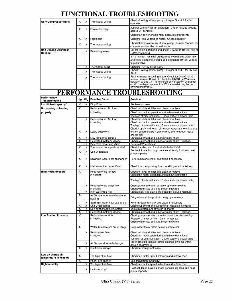
FUNCTIONAL TROUBLESHOOTING
PERFORMANCE TROUBLESHOOTING
OnlyCompressorRuns X X Thermostatwiring CheckGwiringatheatpump.JumperGandRforfanoperation.
X X Fanmotorrelay JumperGandRforfanoperation.CheckforLinevoltageacrossBRcontacts.Checkfanpowerenablerelayoperation(ifpresent)
X X Fanmotor Checkforlinevoltageatmotor.Checkcapacitor
X X Thermostatwiring Checkthermostatwiringatheatpump.JumperYandRforcompressoroperationintestmode.
UnitDoesn'tOperateinCooling X ReversingValve Setforcoolingdemandandcheck24VAConRVcoilandat
CXM/DXMboard.IfRVisstuck,runhighpressureupbyreducingwaterflowandwhileoperatingengageanddisengageRVcoilvoltagetopushvalve.
X Thermostatsetup Checkfor'O'RVsetupnot'B'
X Thermostatwiring CheckOwiringatheatpump.JumperOandRforRVcoil'Click'.
PerformanceTroubleshooting Htg Clg PossibleCause Solution
Insufficientcapacity/ X X DirtyFilter ReplaceorcleanNotcoolingorheating X ReducedornoAirflow Checkfordirtyairfilterandcleanorreplaceproperly inheating Checkfanmotoroperationandairflowrestrictions
Toohighofexternalstatic.CheckstaticvsblowertableX ReducedornoAirflow Checkfordirtyairfilterandcleanorreplace
incooling CheckfanmotoroperationandairflowrestrictionsToohighofexternalstatic.Checkstaticvsblowertable
X X LeakyductworkChecksupplyandreturnairtemperaturesattheunitandatdistantductregistersifsignificantlydifferent,ductleaksarepresent
X X Lowrefrigerantcharge ChecksuperheatandsubcoolingperchartX X Restrictedmeteringdevice Checksuperheatandsubcoolingperchart.Replace.
X DefectiveReversingValve PerformRVtouchtestX X Thermostatimproperlylocated ChecklocationandforairdraftsbehindstatX X Unitundersized Recheckloads&sizingchecksensibleclgloadandheat
pumpcapacity
X X Scalinginwaterheatexchanger PerformScalingcheckandcleanifnecessary
X X InletWatertooHotorCold Checkload,loopsizing,loopbackfill,groundmoisture.
HighHeadPressure X ReducedornoAirflow Checkfordirtyairfilterandcleanorreplaceinheating Checkfanmotoroperationandairflowrestrictions
Toohighofexternalstatic.Checkstaticvsblowertable
X Reducedornowaterflow Checkpumpoperationorvalveoperation/settingincooling Check water flow adjust to proper flow rate
X InletWatertooHot Checkload,loopsizing,loopbackfill,groundmoisture.X AirTemperatureoutofrangein
heating Bringreturnairtempwithindesignparameters
X Scalinginwaterheatexchanger PerformScalingcheckandcleanifnecessaryX X UnitOvercharged Checksuperheatandsubcooling.ReweighinchargeX X Non-condensablesinsystem VacuumsystemandreweighinchargeX X Restrictedmeteringdevice Checksuperheatandsubcoolingperchart.Replace.
LowSuctionPressure X Reducedwaterflow Checkpumpoperationorwatervalveoperation/settinginheating Pluggedstrainerorfilter.Cleanorreplace.
Check water flow adjust to proper flow rate
X WaterTemperatureoutofrange Bringwatertempwithindesignparameters
X ReducedAirflow Checkfordirtyairfilterandcleanorreplaceincooling Checkfanmotoroperationandairflowrestrictions
Toohighofexternalstatic.CheckstaticvsblowertableX AirTemperatureoutofrange Toomuchcoldventair?Bringenteringairtempwithin
designparametersX X Insufficientcharge Checkforrefrigerantleaks
Lowdischargeairtemperatureinheating X Toohighofairflow Checkfanmotorspeedselectionandairflowchart
X PoorPerformance See'InsufficientCapacity'Highhumidity X Toohighofairflow Checkfanmotorspeedselectionandairflowchart
X Unitoversized Recheckloads&sizingchecksensibleclgloadandheatpumpcapacity
X Thermostatwiring Putthermostatincoolingmode.Checkfor24VAConO(checkbetweenCandO);checkfor24VAConW(checkbetweenWandC).ThereshouldbevoltageonO,butnotonW.IfvoltageispresentonW,thermostatmaybebadorwiredincorrectly.
Page 26 Ultra Classic (VT) Series
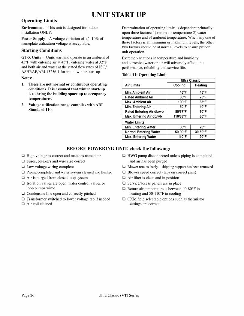
q High voltage is correct and matches nameplateq Fuses, breakers and wire size correctq Low voltage wiring completeq Piping completed and water system cleaned and flushedq Air is purged from closed loop systemq Isolation valves are open, water control valves or loop pumps wiredq Condensate line open and correctly pitchedq Transformer switched to lower voltage tap if needed q Air coil cleaned
q HWG pump disconnected unless piping is completed and air has been purgedq Blower rotates freely – shipping support has been removedq Blower speed correct (taps on correct pins)q Air filter is clean and in positionq Service/access panels are in placeq Return air temperature is between 40-80°F in heating and 50-110°F in coolingq CXM field selectable options such as thermistor settings are correct.
BEFORE POWERING UNIT, check the following:
Operating LimitsEnvironment – This unit is designed for indoor installation ONLY.
Power Supply – A voltage variation of +/– 10% of nameplate utilization voltage is acceptable.
Starting ConditionsGT-X Units – Units start and operate in an ambient of 45°F with entering air at 45°F, entering water at 32°F and both air and water at the stated flow rates of ISO/ASHRAE/ARI 13256-1 for initial winter start-up.
Notes:
1. These are not normal or continuous operating conditions. It is assumed that winter start-up is to bring the building space up to occupancy temperatures.
2. Voltage utilization range complies with ARI Standard 110.
UNIT START UP
UltraClassicAirLimits Cooling Heating
Min.AmbientAir 45°F 45°FRatedAmbientAir 80°F 70°FMax.AmbientAir 100°F 85°FMin.EnteringAir 50°F 40°FRatedEnteringAirdb/wb 80/67°F 70°FMax.EnteringAirdb/wb 110/83°F 80°FWaterLimitsMin.EnteringWater 30°F 20°FNormalEnteringWater 50-90°F 30-60°FMax.EnteringWater 110°F 90°F
Table 11: Operating Limit
Determination of operating limits is dependent primarily upon three factors: 1) return air temperature 2) water temperature and 3) ambient temperature. When any one of these factors is at minimum or maximum levels, the other two factors should be at normal levels to ensure proper unit operation.
Extreme variations in temperature and humidity and corrosive water or air will adversely affect unit performance, reliability and service life.
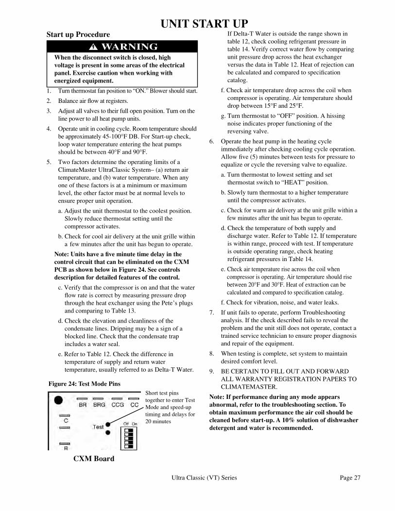
Ultra Classic (VT) Series Page 27
Start up Procedure
When the disconnect switch is closed, high voltage is present in some areas of the electrical panel. Exercise caution when working with energized equipment.
1. Turn thermostat fan position to “ON.” Blower should start.
2. Balance air flow at registers.
3. Adjust all valves to their full open position. Turn on the line power to all heat pump units.
4. Operate unit in cooling cycle. Room temperature should be approximately 45-100°F DB. For Start-up check, loop water temperature entering the heat pumps should be between 40°F and 90°F.
5. Two factors determine the operating limits of a ClimateMaster UltraClassic System– (a) return air temperature, and (b) water temperature. When any one of these factors is at a minimum or maximum level, the other factor must be at normal levels to ensure proper unit operation.
a. Adjust the unit thermostat to the coolest position. Slowly reduce thermostat setting until the compressor activates.
b. Check for cool air delivery at the unit grille within a few minutes after the unit has begun to operate.
Note: Units have a five minute time delay in the control circuit that can be eliminated on the CXM PCB as shown below in Figure 24. See controls description for detailed features of the control.
c. Verify that the compressor is on and that the water flow rate is correct by measuring pressure drop through the heat exchanger using the Pete’s plugs and comparing to Table 13.
d. Check the elevation and cleanliness of the condensate lines. Dripping may be a sign of a blocked line. Check that the condensate trap includes a water seal.
e. Refer to Table 12. Check the difference in temperature of supply and return water temperature, usually referred to as Delta-T Water.
If Delta-T Water is outside the range shown in table 12, check cooling refrigerant pressure in table 14. Verify correct water flow by comparing unit pressure drop across the heat exchanger versus the data in Table 12. Heat of rejection can be calculated and compared to specification catalog.
f. Check air temperature drop across the coil when compressor is operating. Air temperature should drop between 15°F and 25°F.
g. Turn thermostat to “OFF” position. A hissing noise indicates proper functioning of the reversing valve.
6. Operate the heat pump in the heating cycle immediately after checking cooling cycle operation. Allow five (5) minutes between tests for pressure to equalize or cycle the reversing valve to equalize.
a. Turn thermostat to lowest setting and set thermostat switch to “HEAT” position.
b. Slowly turn thermostat to a higher temperature until the compressor activates.
c. Check for warm air delivery at the unit grille within a few minutes after the unit has begun to operate.
d. Check the temperature of both supply and discharge water. Refer to Table 12. If temperature is within range, proceed with test. If temperature is outside operating range, check heating refrigerant pressures in Table 14.
e. Check air temperature rise across the coil when compressor is operating. Air temperature should rise between 20°F and 30°F. Heat of extraction can be calculated and compared to specification catalog.
f. Check for vibration, noise, and water leaks.
7. If unit fails to operate, perform Troubleshooting analysis. If the check described fails to reveal the problem and the unit still does not operate, contact a trained service technician to ensure proper diagnosis and repair of the equipment.
8. When testing is complete, set system to maintain desired comfort level.
9. BE CERTAIN TO FILL OUT AND FORWARD ALL WARRANTY REGISTRATION PAPERS TO CLIMATEMASTER.
Note: If performance during any mode appears abnormal, refer to the troubleshooting section. To obtain maximum performance the air coil should be cleaned before start-up. A 10% solution of dishwasher detergent and water is recommended.
WARNING
UNIT START UP
Short test pins together to enter Test Mode and speed-up timing and delays for 20 minutes
Figure 24: Test Mode Pins
CXM Board
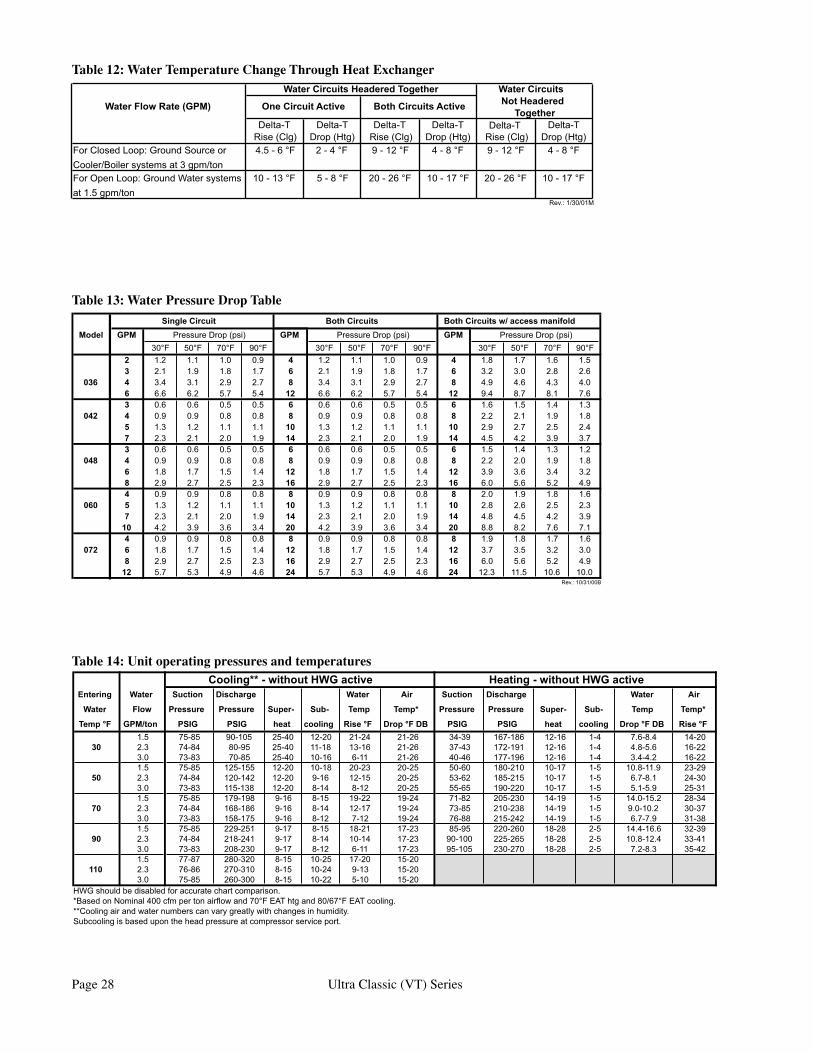
Page 28 Ultra Classic (VT) Series
Table 14: Unit operating pressures and temperatures
Table 12: Water Temperature Change Through Heat Exchanger
Table 13: Water Pressure Drop Table
�������������������������������� ��������������
��������������������� ������������������ �������������������� ��������������������
���������� ���������� ���������� ���������� ���������� ������������������������������������������� ���������� �������� ��������� �������� ��������� ��������
��������������������������������������������������������������������� ���������� �������� ���������� ���������� ���������� ����������
��������������
������� ������� �������������� ��������������
��������������
����������������
�������������� ������������� ��������������������������������
����� ��� ������������������� ��� ������������������� ��� �������������������
���� ���� ���� ���� ���� ���� ���� ���� ���� ���� ���� ����� ��� ��� ��� ��� � ��� ��� ��� ��� � ��� ��� ��� ���� ��� ��� ��� ��� � ��� ��� ��� ��� � ��� ��� ��� ���
��� � ��� ��� ��� ��� � ��� ��� ��� ��� � ��� ��� ��� ���� ��� ��� ��� ��� �� ��� ��� ��� ��� �� ��� ��� ��� ���� ��� ��� ��� ��� � ��� ��� ��� ��� � ��� ��� ��� ���
��� � ��� ��� ��� ��� � ��� ��� ��� ��� � ��� ��� ��� ���� ��� ��� ��� ��� �� ��� ��� ��� ��� �� ��� ��� ��� ���� ��� ��� ��� ��� �� ��� ��� ��� ��� �� ��� ��� ��� ���� ��� ��� ��� ��� � ��� ��� ��� ��� � ��� ��� ��� ���
��� � ��� ��� ��� ��� � ��� ��� ��� ��� � ��� ��� ��� ���� ��� ��� ��� ��� �� ��� ��� ��� ��� �� ��� ��� ��� ���� ��� ��� ��� ��� �� ��� ��� ��� ��� �� ��� ��� ��� ���� ��� ��� ��� ��� � ��� ��� ��� ��� � ��� ��� ��� ���
��� � ��� ��� ��� ��� �� ��� ��� ��� ��� �� ��� ��� ��� ���� ��� ��� ��� ��� �� ��� ��� ��� ��� �� ��� ��� ��� ����� ��� ��� ��� ��� �� ��� ��� ��� ��� �� ��� ��� ��� ���� ��� ��� ��� ��� � ��� ��� ��� ��� � ��� ��� ��� ���
��� � ��� ��� ��� ��� �� ��� ��� ��� ��� �� ��� ��� ��� ���� ��� ��� ��� ��� �� ��� ��� ��� ��� �� ��� ��� ��� ����� ��� ��� ��� ��� �� ��� ��� ��� ��� �� ���� ���� ���� ����
���������������
�������� ���� ���� ���� ������������ ������������������������������������������
������������������������������ ������������������������������������ ����� ������� ��������� ����� ��� ������� ��������� ����� ���
����� ���� �������� �������� ������ ���� ���� ����� �������� �������� ������ ���� ���� �����
������� ������� ���� ���� ���� ������� ������� ���������� ���� ���� ���� ������� ���������� �������
��� ����� ������ ����� ����� ����� ����� ����� ������� ����� ��� ������� ������� ��� ����� ����� ����� ����� ����� ����� ����� ������� ����� ��� ������� �����
��� ����� ����� ����� ����� ���� ����� ����� ������� ����� ��� ������� �������� ����� ������� ����� ����� ����� ����� ����� ������� ����� ��� ��������� �����
�� ��� ����� ������� ����� ���� ����� ����� ����� ������� ����� ��� ������� �������� ����� ������� ����� ���� ���� ����� ����� ������� ����� ��� ������� �������� ����� ������� ���� ���� ����� ����� ����� ������� ����� ��� ��������� �����
�� ��� ����� ������� ���� ���� ����� ����� ����� ������� ����� ��� �������� �������� ����� ������� ���� ���� ���� ����� ����� ������� ����� ��� ������� �������� ����� ������� ���� ���� ����� ����� ����� ������� ����� ��� ��������� �����
�� ��� ����� ������� ���� ���� ����� ����� ������ ������� ����� ��� ��������� �������� ����� ������� ���� ���� ���� ����� ������ ������� ����� ��� ������� �������� ����� ������� ���� ����� ����� �����
��� ��� ����� ������� ���� ����� ���� �������� ����� ������� ���� ����� ���� �����
����������������������������������������������������������������������������������������������������������������������������������������������������������������������������������������������������������������������������������������������������������������������������������������
Ultra Classic (VT) Series Page 29
NOTES

Page 30 Ultra Classic (VT) Series
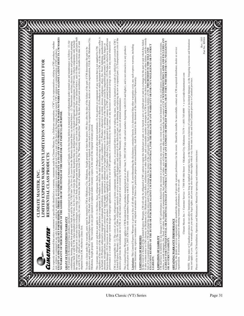
Ultra Classic (VT) Series Page 31
CL
IMA
TE
MA
STE
R, I
NC
.L
IMIT
ED
EX
PR
ESS
WA
RR
AN
TY
/LIM
ITA
TIO
N O
F R
EM
ED
IES
AN
D L
IAB
ILIT
Y F
OR
RE
SID
EN
TIA
L C
LA
SS P
RO
DU
CT
SIt
is e
xpre
ssly
und
erst
ood
that
unl
ess
a st
atem
ent i
s sp
ecif
ical
ly id
enti
fied
as
a w
arra
nty,
sta
tem
ents
mad
e by
Cli
mat
e M
aste
r, I
nc. a
Del
awar
e co
rpor
atio
n, (
“CM
”) o
r it
s re
pres
enta
tive
s, r
elat
ing
to C
M’s
pro
duct
s, w
heth
eror
al, w
ritt
en o
r co
ntai
ned
in a
ny s
ales
lite
ratu
re, c
atal
og o
r ag
reem
ent,
are
not e
xpre
ss w
arra
ntie
s an
d do
not
for
m a
par
t of
the
basi
s of
the
barg
ain,
but
are
mer
ely
CM
’s o
pini
on o
r co
mm
enda
tion
of
CM
’s p
rodu
cts.
EX
CE
PT
AS
SPE
CIF
ICA
LLY
SE
T F
OR
TH
HE
RE
IN, T
HE
RE
IS
NO
EX
PR
ESS
WA
RR
AN
TY
AS
TO
AN
Y O
F C
M’S
PR
OD
UC
TS.
CM
MA
KE
S N
O W
AR
RA
NT
Y A
GA
INST
LA
TE
NT
DE
FE
CT
S. C
M M
AK
ES
NO
WA
RR
AN
TY
OF
ME
RC
HA
NT
AB
ILIT
Y O
F T
HE
GO
OD
S O
R O
F T
HE
FIT
NE
SS O
F T
HE
GO
OD
S F
OR
AN
Y P
AR
TIC
UL
AR
PU
RP
OSE
.
GR
AN
T O
F L
IMIT
ED
EX
PR
ESS
WA
RR
AN
TY
CM
war
rant
s it
s R
esid
enti
al C
lass
pro
duct
s, p
urch
ased
and
ret
aine
d in
the
Uni
ted
Sta
tes
of A
mer
ica
and
Can
ada,
to b
e fr
ee f
rom
def
ects
in m
ater
ial a
nd w
orkm
ansh
ip u
nder
nor
mal
use
and
mai
nten
ance
as
foll
ows:
(1)
Air
cond
itio
ning
, hea
ting
and
/or
heat
pum
p un
its
buil
t or
sold
by
CM
(“C
M U
nits
”) f
or f
ive
(5)
year
s fr
om th
e W
arra
nty
Ince
ptio
n D
ate
(as
defi
ned
belo
w);
(2)
The
rmos
tats
, aux
ilia
ry e
lect
ric
heat
ers
and
geot
herm
al p
umpi
ngm
odul
es b
uilt
or
sold
by
CM
, whe
n in
stal
led
wit
h C
M U
nits
, for
fiv
e (5
) ye
ars
from
the
War
rant
y In
cept
ion
Dat
e (a
s de
fine
d be
low
); (
3) S
eale
d re
frig
eran
t cir
cuit
com
pone
nts
of C
M U
nits
(w
hich
com
pone
nts
only
incl
ude
the
com
pres
sor,
ref
rige
rant
to a
ir/w
ater
hea
t exc
hang
ers,
rev
ersi
ng v
alve
bod
y an
d re
frig
eran
t met
erin
g de
vice
) fo
r te
n (1
0) y
ears
fro
m th
e W
arra
nty
Ince
ptio
n D
ate
(as
defi
ned
belo
w);
and
(4)
Oth
er a
cces
sori
es a
nd p
arts
bui
ltor
sol
d by
CM
, whi
ch a
re n
ot s
uppl
ied
unde
r w
arra
nty,
for
one
(1)
yea
r fr
om th
e da
te o
f sh
ipm
ent f
rom
CM
. The
“W
arra
nty
Ince
ptio
n D
ate”
sha
ll b
e th
e da
te o
f or
igin
al u
nit i
nsta
llat
ion,
or
six
(6)
mon
ths
from
dat
e of
uni
tsh
ipm
ent f
rom
CM
, whi
chev
er c
omes
fir
st.
To m
ake
a cl
aim
und
er th
is w
arra
nty,
par
ts m
ust b
e re
turn
ed to
CM
in O
klah
oma
Cit
y, O
klah
oma,
fre
ight
pre
paid
, no
late
r th
an n
inet
y (9
0) d
ays
afte
r th
e da
te o
f th
e fa
ilur
e of
the
part
; if
CM
det
erm
ines
the
part
to b
ede
fect
ive
and
wit
hin
CM
’s L
imit
ed E
xpre
ss W
arra
nty,
CM
sha
ll, w
hen
such
par
t has
bee
n ei
ther
rep
lace
d or
rep
aire
d, r
etur
n su
ch to
a f
acto
ry r
ecog
nize
d di
stri
buto
r, d
eale
r or
ser
vice
org
aniz
atio
n, F
.O.B
. CM
, Okl
ahom
a C
ity,
Okl
ahom
a, f
reig
ht p
repa
id.
The
war
rant
y on
any
par
t rep
aire
d or
rep
lace
d un
der
war
rant
y ex
pire
s at
the
end
of th
e or
igin
al w
arra
nty
peri
od.
Thi
s w
arra
nty
does
not
cov
er a
nd d
oes
not a
pply
to: (
1) A
ir f
ilte
rs, f
uses
, ref
rige
rant
, flu
ids,
oil
; (2)
Pro
duct
s re
loca
ted
afte
r in
itia
l ins
tall
atio
n; (
3) A
ny p
orti
on o
r co
mpo
nent
of
any
syst
em th
at is
not
sup
plie
d by
CM
,re
gard
less
of
the
caus
e of
the
fail
ure
of s
uch
port
ion
or c
ompo
nent
; (4)
Pro
duct
s on
whi
ch th
e un
it id
enti
fica
tion
tags
or
labe
ls h
ave
been
rem
oved
or
defa
ced;
(5)
Pro
duct
s on
whi
ch p
aym
ent t
o C
M, o
r to
the
owne
r’s
sell
er, i
sin
def
ault
; (6)
Pro
duct
s su
bjec
ted
to im
prop
er o
r in
adeq
uate
inst
alla
tion
, mai
nten
ance
, rep
air,
wir
ing
or v
olta
ge c
ondi
tion
s; (
7) P
rodu
cts
subj
ecte
d to
acc
iden
t, m
isus
e, n
egli
genc
e, a
buse
, fir
e, f
lood
, lig
htni
ng, u
naut
hori
zed
alte
rati
on, m
isap
plic
atio
n, c
onta
min
ated
or
corr
osiv
e ai
r or
liqu
id s
uppl
y, o
pera
tion
at a
bnor
mal
air
or
liqu
id te
mpe
ratu
res
or f
low
rat
es, o
r op
enin
g of
the
refr
iger
ant c
ircu
it b
y un
qual
ifie
d pe
rson
nel;
(8)
Mol
d, f
ungu
s or
bact
eria
dam
ages
; (9)
Cor
rosi
on o
r ab
rasi
on o
f th
e pr
oduc
t; (
10)
Pro
duct
s su
ppli
ed b
y ot
hers
; (11
) P
rodu
cts
whi
ch h
ave
been
ope
rate
d in
a m
anne
r co
ntra
ry to
CM
’s p
rint
ed in
stru
ctio
ns; (
12)
Pro
duct
s w
hich
hav
e in
suff
icie
ntpe
rfor
man
ce a
s a
resu
lt o
f im
prop
er s
yste
m d
esig
n or
impr
oper
app
lica
tion
, ins
tall
atio
n, o
r us
e of
CM
’s p
rodu
cts;
or
(13)
Ele
ctri
city
or
fuel
cos
ts, o
r an
y in
crea
ses
or u
nrea
lize
d sa
ving
s in
sam
e, f
or a
ny r
easo
n w
hats
oeve
r.
CM
is n
ot r
espo
nsib
le f
or: (
1) T
he c
osts
of
any
flui
ds, r
efri
gera
nt o
r sy
stem
com
pone
nts
supp
lied
by
othe
rs, o
r as
soci
ated
labo
r to
rep
air
or r
epla
ce th
e sa
me,
whi
ch is
incu
rred
as
a re
sult
of
a de
fect
ive
part
cov
ered
by
CM
’sL
imit
ed E
xpre
ss W
arra
nty;
(2)
The
cos
ts o
f la
bor,
ref
rige
rant
, mat
eria
ls o
r se
rvic
e in
curr
ed in
dia
gnos
is a
nd r
emov
al o
f th
e de
fect
ive
part
, or
in o
btai
ning
and
rep
laci
ng th
e ne
w o
r re
pair
ed p
art;
(3)
Tra
nspo
rtat
ion
cost
s of
the
defe
ctiv
e pa
rt f
rom
the
inst
alla
tion
sit
e to
CM
, or
of th
e re
turn
of
that
par
t if
not c
over
ed b
y C
M’s
Lim
ited
Exp
ress
War
rant
y; o
r (4
) T
he c
osts
of
norm
al m
aint
enan
ce.
Thi
s L
imit
ed E
xpre
ss W
arra
nty
appl
ies
to C
M R
esid
enti
al C
lass
pro
duct
s m
anuf
actu
red
on o
r af
ter
June
9, 2
003
(CM
Uni
ts w
ith
seri
al n
umbe
rs b
egin
ning
wit
h E
124
and
high
er),
and
is n
ot r
etro
acti
ve to
any
pro
duct
spr
oduc
ed p
rior
to J
une
9, 2
003
(CM
Uni
ts w
ith
seri
al n
umbe
rs b
egin
ning
wit
h E
123
and
low
er).
Lim
itat
ion:
Thi
s L
imit
ed E
xpre
ss W
arra
nty
is g
iven
in li
eu o
f al
l oth
er w
arra
ntie
s. I
f, n
otw
iths
tand
ing
the
disc
laim
ers
cont
aine
d he
rein
, it i
s de
term
ined
that
oth
er w
arra
ntie
s ex
ist,
any
such
exp
ress
war
rant
y, in
clud
ing
wit
hout
lim
itat
ion
any
expr
ess
war
rant
ies
or a
ny im
plie
d w
arra
ntie
s of
fit
ness
for
par
ticu
lar
purp
ose
and
mer
chan
tabi
lity
, sha
ll b
e li
mit
ed to
the
dura
tion
of
the
Lim
ited
Exp
ress
War
rant
y.
LIM
ITA
TIO
N O
F R
EM
ED
IES
In th
e ev
ent o
f a
brea
ch o
f th
e L
imit
ed E
xpre
ss W
arra
nty,
CM
wil
l onl
y be
obl
igat
ed a
t CM
’s o
ptio
n to
rep
air
the
fail
ed p
art o
r un
it, o
r to
fur
nish
a n
ew o
r re
buil
t par
t or
unit
in e
xcha
nge
for
the
part
or
unit
whi
ch h
as f
aile
d.If
aft
er w
ritt
en n
otic
e to
CM
’s f
acto
ry in
Okl
ahom
a C
ity,
Okl
ahom
a of
eac
h de
fect
, mal
func
tion
or
othe
r fa
ilur
e, a
nd a
rea
sona
ble
num
ber
of a
ttem
pts
by C
M to
cor
rect
the
defe
ct, m
alfu
ncti
on o
r ot
her
fail
ure,
and
the
rem
edy
fail
s of
its
esse
ntia
l pur
pose
, CM
sha
ll r
efun
d th
e pu
rcha
se p
rice
pai
d to
CM
in e
xcha
nge
for
the
retu
rn o
f th
e so
ld g
ood(
s). S
aid
refu
nd s
hall
be
the
max
imum
liab
ilit
y of
CM
. TH
IS R
EM
ED
Y I
S T
HE
SO
LE
AN
DE
XC
LU
SIV
E R
EM
ED
Y O
F T
HE
BU
YE
R O
R P
UR
CH
ASE
R A
GA
INST
CM
FO
R B
RE
AC
H O
F C
ON
TR
AC
T, F
OR
TH
E B
RE
AC
H O
F A
NY
WA
RR
AN
TY
OR
FO
R C
M’S
NE
GL
IGE
NC
E O
R I
N S
TR
ICT
LIA
BIL
ITY
.
LIM
ITA
TIO
N O
F L
IAB
ILIT
YC
M s
hall
hav
e no
liab
ilit
y fo
r an
y da
mag
es if
CM
’s p
erfo
rman
ce is
del
ayed
for
any
rea
son
or is
pre
vent
ed to
any
ext
ent b
y an
y ev
ent s
uch
as, b
ut n
ot li
mit
ed to
: any
war
, civ
il u
nres
t, go
vern
men
t res
tric
tion
s or
res
trai
nts,
stri
kes,
or
wor
k st
oppa
ges,
fir
e, f
lood
, acc
iden
t, sh
orta
ges
of tr
ansp
orta
tion
, fue
l, m
ater
ial,
or la
bor,
act
s of
God
or
any
othe
r re
ason
bey
ond
the
sole
con
trol
of
CM
. CM
EX
PR
ESS
LY D
ISC
LA
IMS
AN
D E
XC
LU
DE
S A
NY
LIA
BIL
ITY
FO
R C
ON
SEQ
UE
NT
IAL
OR
IN
CID
EN
TA
L D
AM
AG
E I
N C
ON
TR
AC
T, F
OR
BR
EA
CH
OF
AN
Y E
XP
RE
SS O
R I
MP
LIE
D W
AR
RA
NT
Y, O
R I
N T
OR
T, W
HE
TH
ER
FO
R C
M’s
NE
GL
IGE
NC
EO
R A
S ST
RIC
T L
IAB
ILIT
Y.
OB
TAIN
ING
WA
RR
AN
TY
PE
RF
OR
MA
NC
EN
orm
ally
, the
dea
ler
or s
ervi
ce o
rgan
izat
ion
who
inst
alle
d th
e pr
oduc
ts w
ill p
rovi
de w
arra
nty
perf
orm
ance
for
the
owne
r. S
houl
d th
e in
stal
ler
be u
nava
ilab
le, c
onta
ct a
ny C
M r
ecog
nize
d di
stri
buto
r, d
eale
r or
ser
vice
orga
niza
tion
. If
ass
ista
nce
is r
equi
red
in o
btai
ning
war
rant
y pe
rfor
man
ce, w
rite
or
call
:
Cli
mat
e M
aste
r, I
nc. •
Cus
tom
er S
ervi
ce •
730
0 S
W 4
4th
Str
eet
• O
klah
oma
Cit
y, O
klah
oma
7317
9 •
(40
5) 7
45-6
000
• e
-ser
vice
@cl
imat
emas
ter.c
om
NO
TE
: S
ome
stat
es o
r C
anad
ian
prov
ince
s do
not
all
ow li
mit
atio
ns o
n ho
w lo
ng a
n im
plie
d w
arra
nty
last
s, o
r th
e li
mit
atio
n or
exc
lusi
ons
of c
onse
quen
tial
or
inci
dent
al d
amag
es, s
o th
e fo
rego
ing
excl
usio
ns a
nd li
mit
atio
nsm
ay n
ot a
pply
to y
ou. T
his
war
rant
y gi
ves
you
spec
ific
lega
l rig
hts,
and
you
may
als
o ha
ve o
ther
rig
hts
whi
ch v
ary
from
sta
te to
sta
te a
nd f
rom
Can
adia
n pr
ovin
ce to
Can
adia
n pr
ovin
ce.
Ple
ase
refe
r to
the
CM
Ins
tall
atio
n, O
pera
tion
and
Mai
nten
ance
Man
ual f
or o
pera
ting
and
mai
nten
ance
inst
ruct
ions
.
Rev
.: 5/
03P
art N
o.: R
P40
4
©ClimateMaster2000 Rev.:7/07/05D
ClimateMaster works continually to improve its products. As a result, the design and specifications of each product at the time for order may be changed without notice and may not be as described herein. Please contact ClimateMaster’s Customer Service Department at 1-405-745-6000 for specific informa-tion on the current design and specifications. Statements and other information contained herein are not express warranties and do not form the basis of any bargain between the parties, but are merely ClimateMaster’s opinion or commendation of its products.
7300 S.W. 44th Street Oklahoma City, OK 73179
Phone: 405-745-6000FAX: 405-745-6045
www.climatemaster.com
*69197343* Part # 69197343
PREVENTIVE MAINTENANCEWater Coil Maintenance – (Direct Ground Water Applications Only)If the installation is performed in an area with a known high mineral content (125 P.P.M. or greater) in the water, it is best to establish with the owner a periodic maintenance schedule so the coil can be checked regularly. Consult the well water applications section of this manual for a more detailed water coil material selection. Should periodic coil cleaning be necessary, use standard coil cleaning procedures which are compatible with either the heat exchanger material or copper water lines. Generally, the more water flowing through the unit the less chance for scaling therefore 1.5 gpm per ton is recommended as a minimum flow.
Water Coil Maintenance – (Other Water Loop Applications)Generally water coil maintenance is not needed however, if the installation is located in a system with a known high dirt or debris content, it is best to establish with the owner a periodic maintenance schedule so the coil can be checked regularly. These dirty installations are a result of the deterioration of iron or galvanized piping or components in the system or open cooling towers requiring heavy chemical treatment and mineral buildup through water use. Should periodic coil cleaning be necessary, use standard coil cleaning procedures which are compatible with both the heat exchanger material and copper water lines. Generally, the more water flowing through the unit, the less chance for scaling, however flow rates over 3 gpm per ton can produce water (or debris) velocities that can erode the heat exchanger wall and ultimately produce leaks.
Filters – Filters must be clean to obtain maximum performance. They should be inspected every month under normal operating conditions and be replaced when necessary. Units should never be operated without a filter.
Washable high efficiency electrostatic filters, when dirty, can exhibit a very high pressure drop for the fan motor and reduce air flow resulting in poor performance. With ECM fan motors, excessive fan watts will be used as well. It is especially important to provide consistent washing of these filters (in opposite direction of the normal air flow)
once per month using a high pressure wash similar to that found at self-serve car washes.
Condensate Drain – In areas where airborne bacteria produce a slime in the drain pan, it may be necessary to treat chemically with an algaecide every three months or so to minimize the problem. The condensate pan may also need to be cleaned periodically to assure indoor air quality. The condensate drain can pick up lint and dirt, especially with dirty filters. Inspect the drain twice a year to avoid the possibility of overflow.
Fan Motors - All units have lubricated fan motors. FAN MOTORS SHOULD NEVER BE LUBRICATED UNLESS OBVIOUS, DRY OPERATION IS SUSPECTED. Periodic maintenance oiling is not recommended because it will result in dirt accumulating on excess oil and cause eventual motor failure.
Air Coil – The air coil must be cleaned to obtain maximum performance. Check once a year under normal operating conditions and, if dirty, brush or vacuum clean. Care must be taken not to damage the aluminum fins while cleaning. CAUTION: Fin edges are sharp.
Hot Water Generator Coils – See water coil maintenance for ground water units. If the domestic water is hard or not chemically softened the high temperatures of the desuperheater will tend to "lime up" even quicker than the water coil and may need more frequent inspections.
Cabinet - Do not allow water to stay in contact with the cabinet for long periods of time to prevent corrosion of the cabinet sheet metal. Generally the cabinet is set up from the floor a few inches for prevention. The cabinet can be cleaned using a mild detergent.
Refrigerant System - To maintain sealed circuit integrity, do not install service gauges unless unit operation appears abnormal. Reference the operating chart for pressure and temperatures. Verify that air and water flow rates are at proper levels before servicing the refrigerant circuit.
Related Documents