RESIDENTIAL ONSITE SEWAGE SYSTEMS RULE 410 IAC 6-8.2 This is a guide to the changes from 410 IAC 6-8.1, Residential Sewage Disposal Systems, to 410 IAC 6-8.2, Residential On-Site Sewage Systems. Changes in the requirements are marked with yellow highlighting, or red text noting changes that are not evident from the yellow highlighting. Every effort has been made to mark or indicate every change which results in a change in the requirements for onsite sewage systems, program responsibilities, or procedures. Reorganization and renaming of sections are not marked and cross references which have changed due to the new format are not marked. Also, non-substantial changes, such as making changes for consistency are not marked (such as the use of “pipe” and “effluent sewer” consistently, or “effluent force main” vs. “delivery pipe” or delivery line”). Indiana State Department of Health Environmental Public Health Division 2 N. Meridian St., 5-E Indianapolis, IN 46204 Effective: January 1, 2011 Published 12/21/10

Welcome message from author
This document is posted to help you gain knowledge. Please leave a comment to let me know what you think about it! Share it to your friends and learn new things together.
Transcript

RESIDENTIAL ONSITE SEWAGE SYSTEMS RULE 410 IAC 6-8.2
This is a guide to the changes from 410 IAC 6-8.1, Residential Sewage Disposal Systems, to 410 IAC 6-8.2, Residential On-Site Sewage Systems. Changes in the requirements are marked with yellow highlighting, or red text noting changes that are not evident from the yellow highlighting. Every effort has been made to mark or indicate every change which results in a change in the requirements for onsite sewage systems, program responsibilities, or procedures. Reorganization and renaming of sections are not marked and cross references which have changed due to the new format are not marked. Also, non-substantial changes, such as making changes for consistency are not marked (such as the use of “pipe” and “effluent sewer” consistently, or “effluent force main” vs. “delivery pipe” or delivery line”).
Indiana State Department of Health Environmental Public Health Division
2 N. Meridian St., 5-E Indianapolis, IN 46204
Effective: January 1, 2011
Published 12/21/10

410 IAC 6-8.2
TABLE OF CONTENTS
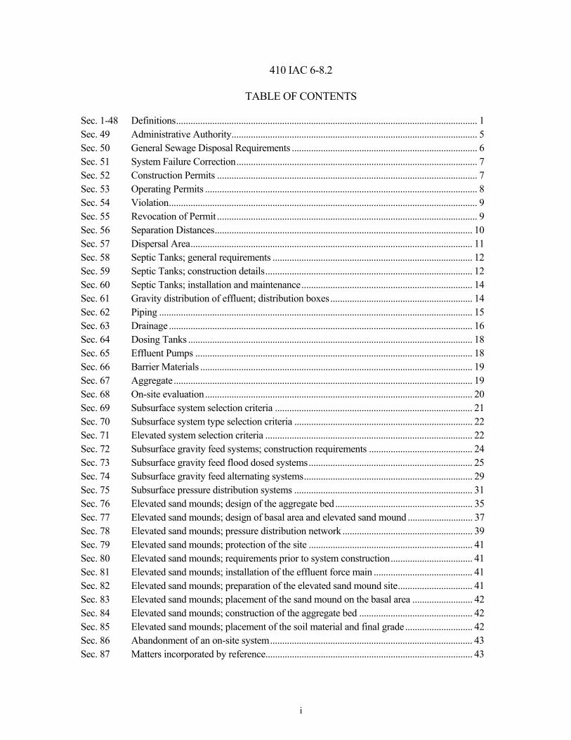
Sec. 1-48 Definitions ............................................................................................................................. 1 Sec. 49 Administrative Authority ...................................................................................................... 5 Sec. 50 General Sewage Disposal Requirements ............................................................................. 6 Sec. 51 System Failure Correction .................................................................................................... 7 Sec. 52 Construction Permits ............................................................................................................ 7 Sec. 53 Operating Permits ................................................................................................................. 8 Sec. 54 Violation ................................................................................................................................ 9 Sec. 55 Revocation of Permit ............................................................................................................ 9 Sec. 56 Separation Distances ........................................................................................................... 10 Sec. 57 Dispersal Area ..................................................................................................................... 11 Sec. 58 Septic Tanks; general requirements ................................................................................... 12 Sec. 59 Septic Tanks; construction details ...................................................................................... 12 Sec. 60 Septic Tanks; installation and maintenance ....................................................................... 14 Sec. 61 Gravity distribution of effluent; distribution boxes ........................................................... 14 Sec. 62 Piping .................................................................................................................................. 15 Sec. 63 Drainage .............................................................................................................................. 16 Sec. 64 Dosing Tanks ...................................................................................................................... 18 Sec. 65 Effluent Pumps ................................................................................................................... 18 Sec. 66 Barrier Materials ................................................................................................................. 19 Sec. 67 Aggregate ............................................................................................................................ 19 Sec. 68 On-site evaluation ............................................................................................................... 20 Sec. 69 Subsurface system selection criteria .................................................................................. 21 Sec. 70 Subsurface system type selection criteria .......................................................................... 22 Sec. 71 Elevated system selection criteria ...................................................................................... 22 Sec. 72 Subsurface gravity feed systems; construction requirements ........................................... 24 Sec. 73 Subsurface gravity feed flood dosed systems .................................................................... 25 Sec. 74 Subsurface gravity feed alternating systems ...................................................................... 29 Sec. 75 Subsurface pressure distribution systems .......................................................................... 31 Sec. 76 Elevated sand mounds; design of the aggregate bed ......................................................... 35 Sec. 77 Elevated sand mounds; design of basal area and elevated sand mound ........................... 37 Sec. 78 Elevated sand mounds; pressure distribution network ...................................................... 39 Sec. 79 Elevated sand mounds; protection of the site .................................................................... 41 Sec. 80 Elevated sand mounds; requirements prior to system construction .................................. 41 Sec. 81 Elevated sand mounds; installation of the effluent force main ......................................... 41 Sec. 82 Elevated sand mounds; preparation of the elevated sand mound site ............................... 41 Sec. 83 Elevated sand mounds; placement of the sand mound on the basal area ......................... 42 Sec. 84 Elevated sand mounds; construction of the aggregate bed ............................................... 42 Sec. 85 Elevated sand mounds; placement of the soil material and final grade ............................ 42 Sec. 86 Abandonment of an on-site system .................................................................................... 43 Sec. 87 Matters incorporated by reference...................................................................................... 43
i
ii
410 IAC 6-8.2
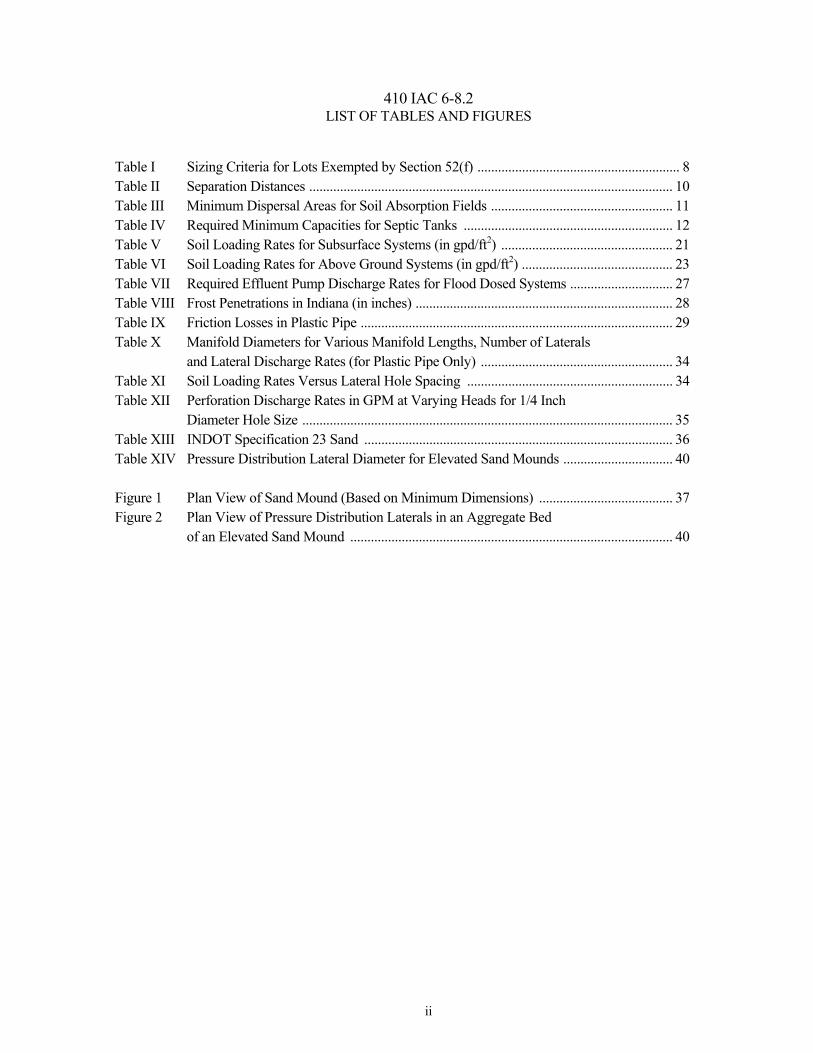
LIST OF TABLES AND FIGURES Table I Sizing Criteria for Lots Exempted by Section 52(f) ........................................................... 8 Table II Separation Distances .......................................................................................................... 10 Table III Minimum Dispersal Areas for Soil Absorption Fields ..................................................... 11 Table IV Required Minimum Capacities for Septic Tanks ............................................................. 12 Table V Soil Loading Rates for Subsurface Systems (in gpd/ft2) .................................................. 21 Table VI Soil Loading Rates for Above Ground Systems (in gpd/ft2) ............................................ 23 Table VII Required Effluent Pump Discharge Rates for Flood Dosed Systems .............................. 27 Table VIII Frost Penetrations in Indiana (in inches) ........................................................................... 28 Table IX Friction Losses in Plastic Pipe ........................................................................................... 29 Table X Manifold Diameters for Various Manifold Lengths, Number of Laterals
and Lateral Discharge Rates (for Plastic Pipe Only) ........................................................ 34 Table XI Soil Loading Rates Versus Lateral Hole Spacing ............................................................ 34 Table XII Perforation Discharge Rates in GPM at Varying Heads for 1/4 Inch
Diameter Hole Size ............................................................................................................ 35 Table XIII INDOT Specification 23 Sand .......................................................................................... 36 Table XIV Pressure Distribution Lateral Diameter for Elevated Sand Mounds ................................ 40 Figure 1 Plan View of Sand Mound (Based on Minimum Dimensions) ....................................... 37 Figure 2 Plan View of Pressure Distribution Laterals in an Aggregate Bed
of an Elevated Sand Mound .............................................................................................. 40
410 IAC 6-8.2: Residential On-Site Sewage Systems 410 IAC 6-8.2-1 Definitions
Sec. 1. The definitions in this rule apply throughout this rule.
410 IAC 6-8.2-2 "AASHTO" defined [NEW]
Sec. 2. "AASHTO" means American Association of State Highway and Transportation Officials.
410 IAC 6-8.2-3 "ABS" defined
Sec. 3. "ABS" means acrylonitrile-butadiene-styrene.
410 IAC 6-8.2-4 "ANSI" defined [NEW]
Sec. 4. "ANSI" means American National Standards Institute.
410 IAC 6-8.2-5 "ASTM" defined
Sec. 5. "ASTM" means American Society for Testing and Materials.
410 IAC 6-8.2-6 "Bedroom" defined [NEW]
Sec. 6. "Bedroom" means either any room: (1) in a residence that the local health department and the owner agree could be occupied for the purpose of sleeping and contains an area of seventy (70) square feet or more, at least one (1) operable window or exterior door for emergency egress or rescue, and, for new construction, a closet; or (2) declared by the owner, by recorded affidavit supplied to the local health department, that will be occupied for sleeping, and that the owner further agrees within the affidavit not to occupy any additional rooms for the purpose of sleeping or otherwise represent to others that any room, beyond the number specified in the affidavit, may be utilized for sleeping, without approval of the local health department.
410 IAC 6-8.2-7 "Bedroom equivalent" defined [NEW]
Sec. 7. "Bedroom equivalent" means any jetted bathtub with a capacity of greater than one hundred twenty-five (125) gallons.
410 IAC 6-8.2-8 "Commissioner" defined
Sec. 8. "Commissioner" means the commissioner of the Indiana state department of health or his or her legally authorized representative.
410 IAC 6-8.2-9 "Construction permit" defined [NEW]
Sec. 9. "Construction permit" means written approval by a local health department for the installation of a residential on-site sewage system.
410 IAC 6-8.2-10 "Densic material" defined [NEW]
Sec. 10. "Densic material" means relatively unaltered materials (do not meet requirements for any other named diagnostic horizons nor any other diagnostic soil characteristic) that have a noncemented rupture resistance class. The bulk density or the organization is such that roots cannot enter, except in cracks. These are mostly earthy materials, such as till, volcanic mudflows, and some mechanically compacted materials. Some noncemented rock can be densic materials if they are dense or resistant enough to keep roots from entering, except in cracks. Densic materials are noncemented and thus differ from paralithic materials and the material below a lithic contact, both of which are cemented. Densic materials have, at their upper boundary, a densic contact if they have no cracks or if the spacing of cracks that roots can enter is ten (10) centimeters (cm) or more. These materials can be used to differentiate soil series if the materials are within the series control section.
410 IAC 6-8.2-11 "Department" defined [NEW]
Sec. 11. "Department" means the Indiana state department of health. [Replaces the definition of “board”]
1

Section 12
410 IAC 6-8.2-12 "Design daily flow" or "DDF" defined [NEW] Sec. 12. "Design daily flow" or "DDF" means the calculated peak daily wastewater flow from a residence used to design a residential on-site sewage system. It is one hundred fifty (150) gallons per day times the number of bedrooms and bedroom equivalents.
410 IAC 6-8.2-13 "Distribution box" defined
Sec. 13. "Distribution box" means a structure designed to distribute effluent by gravity from a septic tank equally into the pipes of an absorption system connected thereto. 410 IAC 6-8.2-14 "Drainageway" defined Sec. 14. "Drainageway" means the channel portion of the landscape in which surface water or rainwater runoff gathers intermittently to flow to a lower elevation.
410 IAC 6-8.2-15 "Dwelling" or "residence" defined
Sec. 15. "Dwelling" or "residence" means any house or place used or intended to be used as a place of seasonal or permanent human habitation or for sleeping for one (1) or two (2) families, and any associated outbuildings that are for the private use of the owner.
410 IAC 6-8.2-16 "Fill" defined
Sec. 16. "Fill" means soil transported and deposited by man, as well as soil recently transported and deposited by natural erosion forces. Fill is evidenced by one (1) or more of the following:
(1) No soil horizons or indistinct soil horizons. (2) Depositional stratification. (3) Presence of a soil horizon that has been covered. (4) Materials in a horizon such as cinders or construction debris. (5) Position in the landscape.
410 IAC 6-8.2-17 "Foundation drain" defined
Sec. 17. "Foundation drain" means that portion of a residential drainage system provided to drain only ground water from outside of the foundation of the house or from under the basement floor.
410 IAC 6-8.2-18 "Health officer" defined
Sec. 18. "Health officer" means the health officer of a local board of health.
410 IAC 6-8.2-19 "INDOT" defined [NEW]
Sec. 19. "INDOT" means the Indiana department of transportation.
410 IAC 6-8.2-20 "Interceptor drain" defined [NEW]
Sec. 20. "Interceptor drain" means a subsurface drainage system constructed only on the upslope side of a soil absorption field for the purpose of diverting subsurface water around the soil absorption field site.
410 IAC 6-8.2-21 "NEMA" defined [NEW]
Sec. 21. "NEMA" means National Electrical Manufacturers Association.
410 IAC 6-8.2-22 "NRCS" defined [NEW]
Sec. 22. "NRCS" means United States Department of Agriculture, Natural Resources Conservation Service. [Replaces the definition of “SCS”]
410 IAC 6-8.2-23 "NSF" defined [NEW]
Sec. 23. "NSF" means NSF International.
410 IAC 6-8.2-24 "Operating permit" defined [NEW]
Sec. 24. "Operating permit" means written approval by a local health department for the continued use of an on-site system. 410 IAC 6-8.2-25 "Owner" defined
2
Section 25
Sec. 25. "Owner" means the owner of a dwelling or his or her agent. 410 IAC 6-8.2-26 "Perimeter drain" defined [NEW] Sec. 26. "Perimeter drain" means a subsurface drainage system that completely surrounds a soil absorption field for the purpose of lowering a seasonal high water table or preventing movement of subsurface water into a soil absorption field site. 410 IAC 6-8.2-27 "Person" defined Sec. 27. "Person" means any:
(1) individual; (2) partnership; (3) copartnership; (4) firm; (5) company; (6) corporation; (7) association; (8) trust; (9) estate; or (10) other legal entity, its or their successors, or assigns or agents of the aforesaid.
410 IAC 6-8.2-28 "PVC" defined Sec. 28. "PVC" means polyvinyl chloride. 410 IAC 6-8.2-29 "Residential drain" defined Sec. 29. "Residential drain" means the horizontal piping in a house drainage system that receives the discharge from soil, waste, and drainage pipes inside the walls of the house and conveys the same to the residential sewer. 410 IAC 6-8.2-30 "Residential on-site sewage system" or "on-site system" defined Sec. 30. "Residential on-site sewage system" or "on-site system" means all equipment and devices necessary for proper conduction, collection, storage, treatment, and on-site disposal of sewage from:
(1) a one (1) or two (2) family dwelling; or (2) two (2) single family dwellings on the same property with a combined DDF of less than seven hundred fifty (750) gallons per day.
Included within, but not limited to, the scope of this definition are residential sewers, septic tanks, soil absorption systems, temporary sewage holding tanks, and sanitary vault privies. [Replaces the definition of “residential sewage disposal system”. Throughout the rule, this change in terminology was made.] 410 IAC 6-8.2-31 "Residential on-site sewage system failure" defined [TERM CHANGED; definition unchanged] Sec. 31. "Residential on-site sewage system failure" means a residential on-site sewage system that exhibits one (1) or more of the following:
(1) The system refuses to accept sewage at the rate of design application thereby interfering with the normal use of residential plumbing fixtures. (2) Effluent discharge exceeds the absorptive capacity of the soil, resulting in ponding, seepage, or other discharge of the effluent to the ground surface or to surface waters. (3) Effluent is discharged from the system causing contamination of a potable water supply, ground water, or surface waters.
A failed residential on-site sewage system is a health hazard. [Replaces the definition of “Residential sewage disposal system failure”] 410 IAC 6-8.2-32 "Residential outbuilding" defined [NEW] Sec. 32. "Residential outbuilding" means a building for the private use of the owner not intended to be used for permanent or seasonal human habitation or sleeping.
3
Section 33
410 IAC 6-8.2-33 "Residential sewer" defined Sec. 33. "Residential sewer" means the horizontal piping beginning two (2) feet outside the house that carries discharges from the residential drain to its connection with a sanitary sewerage system or a residential on-site sewage system. 410 IAC 6-8.2-34 "Sanitary sewerage system" defined Sec. 34. "Sanitary sewerage system" means a sewer or a system of sewers that convey sewage away from the lot on which it originates to a wastewater treatment facility owned and operated by:
(1) an incorporated city or town; (2) a conservancy district; (3) a regional sewer district; or (4) a private utility.
410 IAC 6-8.2-35 "SDR" defined Sec. 35. "SDR" means standard dimension ratio. 410 IAC 6-8.2-36 "Seasonal high water table" defined [NEW] Sec. 36. "Seasonal high water table" means the upper limit of soil saturated with water for periods long enough for anaerobic conditions to affect soil color. 410 IAC 6-8.2-37 "Segment drain" defined [NEW] Sec. 37. "Segment drain" means a subsurface drainage system constructed between two (2) soil absorption fields in the same on-site system for the purpose of intercepting and diverting subsurface water away from the downslope soil absorption field. 410 IAC 6-8.2-38 "Septic tank" defined Sec. 38. "Septic tank" means a watertight structure into which sewage is discharged for settling and solids digestion. 410 IAC 6-8.2-39 "Sewage" defined Sec. 39. "Sewage" means all water-carried waste derived from ordinary living processes.
[The definition of “sludge” was removed because the word is not used in the rule.] 410 IAC 6-8.2-40 "Soil absorption" defined Sec. 40. "Soil absorption" means a process that utilizes the soil to treat and dispose of effluent from a septic tank. 410 IAC 6-8.2-41 "Soil absorption system" defined Sec. 41. "Soil absorption system" means pipes or chambers laid in a system of trenches or elevated beds into which the effluent from the septic tank is discharged for soil absorption. 410 IAC 6-8.2-42 "Soil horizon" defined Sec. 42. "Soil horizon" means a layer of soil or soil material approximately parallel to the land surface and differing from adjacent genetically related layers in physical, chemical, and biological properties or characteristics such as:
(1) color; (2) structure; (3) texture; (4) consistency; (5) kinds and numbers of organisms present; and (6) degree of acidity or alkalinity
410 IAC 6-8.2-43 "Soil loading rate" defined [TERM CHANGED; definition unchanged]
Sec. 43. "Soil loading rate" means the allowable rate of application of septic tank effluent to the soil. It is expressed in gallons per day per square foot. [Replaces the definition of “loading rate”]
4
Section 44
410 IAC 6-8.2-44 "Soil profile analysis" defined
Sec. 44. "Soil profile analysis" means the observation and evaluation of the physical characteristics of the soil horizons or layers to a depth of at least five (5) feet or, if shallower, to a layer that cannot be readily penetrated.
410 IAC 6-8.2-45 "Soil scientist" defined
Sec. 45. "Soil scientist" means an individual registered as a professional soil scientist with the Indiana Registry of Soil Scientists (IRSS) as provided for under IC 25-31.5.
410 IAC 6-8.2-46 "Start of construction" defined [NEW]
Sec. 46. "Start of construction" means, but is not limited to, any site activity undertaken for the erection of the structure to be served by a residential on-site sewage system or the delivery of manufactured housing.
410 IAC 6-8.2-47 "Subsurface drainage system" defined [NEW]
Sec. 47. "Subsurface drainage system" means any pipe and a layer of gravel, stone or coarse sand, or any combination of these components placed below the surface of the ground and designed or constructed in such a manner as to:
(1) effectively lower a seasonal high water table; or (2) prevent movement of subsurface water into a soil absorption field site.
Interceptor drains, perimeter drains, and segment drains are types of subsurface drainage systems.
410 IAC 6-8.2-48 "Technology new to Indiana" or "TNI" defined [NEW]
Sec. 48. "Technology new to Indiana" or "TNI" means on-site sewage treatment or disposal methods, processes, or equipment not described in this rule that have been approved by the department in accordance with section 50(g) of this rule.
410 IAC 6-8.2-49 Administrative authority
Sec. 49. (a) This rule shall be administered by the local boards of health through their health officer and his or her authorized representatives. (b) Local boards of health that wish to adopt or amend a local ordinance governing the design, construction, and operation of residential on-site sewage systems shall do so only after the department has confirmed in writing that the ordinance does not violate this rule or state sewage disposal statutes. Nothing in this rule shall be construed as prohibiting more stringent requirements in local ordinances. (c) Each local health department residential on-site sewage system permit program is subject to review by the department. Such review may include, but not be limited to, a review of the permits issued, supporting documentation, and a review of system installations. (d) Whenever the department determines that there has been a violation of this rule, the department shall notify the health officer. The notice shall:
(1) be in writing; (2) be sent to the health officer by certified mail; (3) include a statement of the reasons for the issuance of the notice; (4) specify the remedial action necessary to effect compliance with the rule; and (5) allow reasonable time as determined by the department for the performance of any act it requires to correct the problem.
(e) If a health officer fails to comply with a directive issued in accordance with subsection (d), the department may require the health officer to submit all, or any portion thereof deemed appropriate by the department, of the construction permits proposed for issuance for residential on-site sewage system construction, together with all documentation upon which the proposed permit issuance will be based, to the department for review and written approval prior to permit issuance by the health officer. The review shall continue until the department is satisfied that compliance with the rule has been obtained and is likely to continue, and has so notified the health officer in writing.
5

Section 50
410 IAC 6-8.2-50 General sewage disposal requirements
Sec. 50. (a) No person shall throw, run, drain, seep, or otherwise dispose into any of the surface waters or ground waters of this state, or cause, permit, or suffer to be thrown, run, drained, allowed to seep, or otherwise disposed into such waters, any organic or inorganic matter from a dwelling or residential on-site sewage system that would cause or contribute to a health hazard or water pollution. (b) The:
(1) design; (2) construction; (3) installation; (4) location; (5) maintenance; and (6) operation;
of residential on-site sewage systems shall comply with the provisions of this rule. (c) All residential on-site sewage systems utilizing sanitary privies shall conform to Indiana state department of health bulletin SE 11, "The Sanitary Vault Privy", 1986 Edition. (d) Any dwelling that is not connected, or cannot be connected, to a sanitary sewerage system shall be provided with a residential on-site sewage system that includes a septic tank and a soil absorption system that has not failed. (e) A temporary sewage holding tank is an alternative method of sewage disposal subject to the written approval of the department required in subsection (f), except as provided in subdivisions (1) through (3). A temporary sewage holding tank shall not be used as a primary means of residential sewage disposal except where necessary to prevent continued discharge of wastewater from a failed existing residential on-site sewage system, or when soil conditions exist that preclude the prompt construction of a soil absorption field on a site that has already received a construction permit. A temporary sewage holding tank may be approved by the local health department:
(1) as a temporary storage facility where occupancy of the home must continue while an existing system is being replaced or renovated; Note: the one year limitation is removed from this subsection. (2) until soil conditions permit the installation of a soil absorption field for which a construction permit has been issued; or (3) where such facility is owned and operated temporarily by a conservancy district, sewer district, private utility, or municipality as a part of its sewage disposal plan or for not more than one (1) year while connection to sanitary sewer is being secured.
(f) If any conditions preclude the installation of a residential on-site sewage system as described in this rule, the local board of health may not approve the use of any other residential on-site sewage system technology unless written approval from the department is:
(1) issued, under subsection (g), for local health departments to issue construction permits for the use of the technology; or (2) obtained for specific applications.
(g) In order to permit development of new or more efficient sewage treatment or disposal processes, the department may approve the installation of experimental equipment, facilities, or pollution control devices for which extensive experience or records of use have not been developed in Indiana. The applicant for such approval must submit evidence of sufficient clarity and conclusiveness to convince the department that the proposal has a reasonable and substantial probability of satisfactory operation without failure. (h) No portion of the residential on-site sewage system or its associated drainage system shall be constructed upon property other than that from which the sewage originates unless easements, which grant permission for such construction and access for system maintenance, have been obtained for that property and have been legally approved and recorded by the proper authority or commission. (i) Residential on-site sewage systems shall not be used for the disposal of water from:
(1) roof drains; (2) foundation drains; (3) swimming pool main drains; (4) hot tub drains; or
6
Section 50(i)(5)
(5) area drains. Neither shall they be used for the disposal of chemical wastes in quantities that would pollute ground water or inhibit solids settling or digestion in the septic tank. (j) Any jetted bathtub with a capacity of greater than one hundred twenty-five (125) gallons will be treated as an extra bedroom for the on-site system sizing requirements of this rule.
410 IAC 6-8.2-51 System failure correction
Sec. 51. Should a residential on-site sewage system fail, the failure shall be corrected by the owner within the time limit set by the health officer.
410 IAC 6-8.2-52 Construction permits
Sec. 52. (a) The owner or agent of the owner shall obtain a written construction permit, signed by the health officer, for construction of a residential on-site sewage system prior to the following:
(1) Start of construction of a residence or placement of a mobile home that will not be connected to a sanitary sewerage system. (2) Any:
(A) replacement; (B) reconstruction; (C) expansion; or (D) remodeling;
of a residence that may increase the number of bedrooms. (3) Any addition to, alteration of, or repair of an existing residential on-site sewage system.
(b) The application for such a permit shall be made on a form approved by the department, which application shall contain information outlined in section 68 of this rule, the profile analysis of all the soils in which the residential on-site sewage system is to be constructed, plans of sufficient clarity that it can be verified that the design of the residential on-site sewage system shall comply with the provisions of this rule, and any other information deemed necessary by the health officer. The local health department may require scale drawings of the site and residential on-site sewage system as part of the application process. Other than the approval referenced in subsection (f), the approval of a site by the local plan commission or the county recorder does not constitute approval by the local health officer. Approval of a soil absorption field replacement for a residential on-site sewage system by a local health department shall be made in accordance with the provisions of this rule. When replacement is necessary due to system failure, [Note: “defect” and “malfunction” have been removed] deviations to this rule for a soil absorption field replacement shall be made in accordance with the best judgment of the local department of health, based on the:
(1) limitations of the site; (2) results of a written on-site system evaluation; and (3) results of the written soil profile analysis.
(c) Soil absorption field replacement for a residential on-site system shall not be: (1) contrary to section 50(a) of this rule; and (2) constructed to a depth greater than forty-eight (48) inches below final grade in any portion of a subsurface soil absorption field.
(d) A local health department shall not issue a construction permit for repair of an on-site system or replacement of a soil absorption field using TNI without the written approval of the department, except for the provisions of section 50(f) of this rule. (e) If it is determined that the proposed on-site system design does not meet the minimum requirements of this rule, the permit shall be denied and the owner shall be notified in writing of the basis for the denial. The notification shall also state that the owner has the right to appeal the denial and shall state the procedure for registering any such appeal. In accordance with IC 16-41-25-1(a), the local health department shall issue or deny, in writing to the owner, a residential on-site system construction permit within forty-five (45) days of receipt of an application and plan submittal. (f) Individual lots in subdivisions designed to utilize on-site residential on-site sewage systems, for which the plats were approved by the local plan commission, county health department, or the county recorder, and recorded prior to December 21, 1990, are exempt from the provisions of sections 69(4) and 72(a) of this rule if the soils on the individual lot have characteristics that would allow the soil to be rated slight or moderate in
7
Section 52(f)
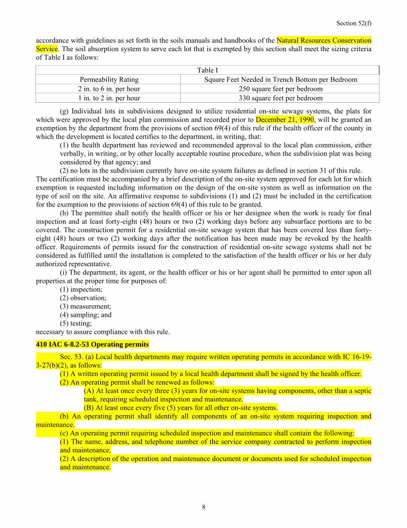
accordance with guidelines as set forth in the soils manuals and handbooks of the Natural Resources Conservation Service. The soil absorption system to serve each lot that is exempted by this section shall meet the sizing criteria of Table I as follows:
Table I Permeability Rating Square Feet Needed in Trench Bottom per Bedroom 2 in. to 6 in. per hour 250 square feet per bedroom 1 in. to 2 in. per hour 330 square feet per bedroom
(g) Individual lots in subdivisions designed to utilize residential on-site sewage systems, the plats for which were approved by the local plan commission and recorded prior to December 21, 1990, will be granted an exemption by the department from the provisions of section 69(4) of this rule if the health officer of the county in which the development is located certifies to the department, in writing, that:
(1) the health department has reviewed and recommended approval to the local plan commission, either verbally, in writing, or by other locally acceptable routine procedure, when the subdivision plat was being considered by that agency; and (2) no lots in the subdivision currently have on-site system failures as defined in section 31 of this rule.
The certification must be accompanied by a brief description of the on-site system approved for each lot for which exemption is requested including information on the design of the on-site system as well as information on the type of soil on the site. An affirmative response to subdivisions (1) and (2) must be included in the certification for the exemption to the provisions of section 69(4) of this rule to be granted. (h) The permittee shall notify the health officer or his or her designee when the work is ready for final inspection and at least forty-eight (48) hours or two (2) working days before any subsurface portions are to be covered. The construction permit for a residential on-site sewage system that has been covered less than forty-eight (48) hours or two (2) working days after the notification has been made may be revoked by the health officer. Requirements of permits issued for the construction of residential on-site sewage systems shall not be considered as fulfilled until the installation is completed to the satisfaction of the health officer or his or her duly authorized representative. (i) The department, its agent, or the health officer or his or her agent shall be permitted to enter upon all properties at the proper time for purposes of:
(1) inspection; (2) observation; (3) measurement; (4) sampling; and (5) testing;
necessary to assure compliance with this rule.
410 IAC 6-8.2-53 Operating permits
Sec. 53. (a) Local health departments may require written operating permits in accordance with IC 16-19-3-27(b)(2), as follows:
(1) A written operating permit issued by a local health department shall be signed by the health officer. (2) An operating permit shall be renewed as follows:
(A) At least once every three (3) years for on-site systems having components, other than a septic tank, requiring scheduled inspection and maintenance. (B) At least once every five (5) years for all other on-site systems.
(b) An operating permit shall identify all components of an on-site system requiring inspection and maintenance. (c) An operating permit requiring scheduled inspection and maintenance shall contain the following:
(1) The name, address, and telephone number of the service company contracted to perform inspection and maintenance. (2) A description of the operation and maintenance document or documents used for scheduled inspection and maintenance.
8

Section 53(d)
(d) The owner shall provide the local health department with the following: (1) Written documentation of all scheduled and unscheduled inspection and maintenance within one (1) month of the date performed. (2) A copy of the inspection and maintenance contract.
410 IAC 6-8.2-54 Violation
Sec. 54. (a) Any person found to be violating this rule may be served by the health officer with a written order stating the nature of the violation and providing a time limit for satisfactory correction thereof. (b) After receiving an order in writing from the local board of health or the health officer, the owner of the property shall comply with the provisions of this rule as set forth in the order and within the time limit specified therein. The order shall be served on the owner or the agent of the owner, but may be served on any person who, by contract with the owner, has assumed the duty of complying with the provisions of an order.
410 IAC 6-8.2-55 Revocation of permit
Sec. 55. (a) If an applicant is refused a permit, the local board of health shall, upon request, afford the applicants the opportunity for a fair hearing. The parties involved may agree to use the procedures set forth in IC 4-21.5, the Administrative Orders and Procedures Act. (b) The local board of health may revoke a permit that had been issued for the construction or operation of a residential on-site sewage system if it finds that the owner of the permit has failed to comply with this rule. Upon such notice, the local board shall, upon request, afford the applicant the opportunity for a fair hearing. The parties involved may agree to use the procedures set forth in IC 4-21.5, the Administrative Orders and Procedures Act.
9
Section 56
410 IAC 6-8.2-56 Separation distances
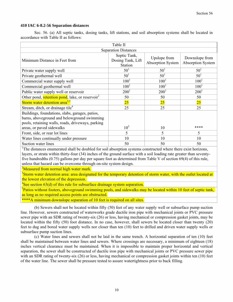
Sec. 56. (a) All septic tanks, dosing tanks, lift stations, and soil absorption systems shall be located in accordance with Table II as follows:
Table II Separation Distances
Minimum Distance in Feet from Septic Tank,
Dosing Tank, Lift Station
Upslope from Absorption System
Downslope from Absorption System
Private water supply well 501 501 501 Private geothermal well 501 501 501 Commercial water supply well 1001 1001 1001 Commercial geothermal well 1001 1001 1001 Public water supply well or reservoir 2001 2001 2001 Other pond, retention pond, lake, or reservoir2 50 50 50 Storm water detention area2,3 25 25 25 Stream, ditch, or drainage tile4 25 25 25 Buildings, foundations, slabs, garages, patios, barns, aboveground and belowground swimming pools, retaining walls, roads, driveways, parking areas, or paved sidewalks 105 10 **** Front, side, or rear lot lines 5 5 5 Water lines continually under pressure 10 10 10 Suction water lines 50 50 50 1The distances enumerated shall be doubled for soil absorption systems constructed where there exist horizons, layers, or strata within thirty-four (34) inches of the ground surface with a soil loading rate greater than seventy-five hundredths (0.75) gallons per day per square foot as determined from Table V of section 69(4) of this rule, unless that hazard can be overcome through on-site system design. 2Measured from normal high water mark. 3Storm water detention area: area designated for the temporary detention of storm water, with the outlet located at the lowest elevation of the depression. 4See section 63(d) of this rule for subsurface drainage system separation.5Patios without footers, aboveground swimming pools, and sidewalks may be located within 10 feet of septic tank, as long as no required access points are obstructed. ****A minimum downslope separation of 10 feet is required on all sites.
(b) Sewers shall not be located within fifty (50) feet of any water supply well or subsurface pump suction line. However, sewers constructed of waterworks grade ductile iron pipe with mechanical joints or PVC pressure sewer pipe with an SDR rating of twenty-six (26) or less, having mechanical or compression gasket joints, may be located within the fifty (50) foot distance. In no case, however, shall sewers be located closer than twenty (20) feet to dug and bored water supply wells nor closer than ten (10) feet to drilled and driven water supply wells or subsurface pump suction lines. (c) Water lines and sewers shall not be laid in the same trench. A horizontal separation of ten (10) feet shall be maintained between water lines and sewers. Where crossings are necessary, a minimum of eighteen (18) inches vertical clearance must be maintained. When it is impossible to maintain proper horizontal and vertical separation, the sewer shall be constructed of ductile iron pipe with mechanical joints or PVC pressure sewer pipe with an SDR rating of twenty-six (26) or less, having mechanical or compression gasket joints within ten (10) feet of the water line. The sewer shall be pressure tested to assure watertightness prior to back filling.
10
Section 57
410 IAC 6-8.2-57 Dispersal area
Sec. 57. (a) A dispersal area is required for all soil absorption fields: (1) when the soil loading rate used to determine the size of the soil absorption field is five-tenths (0.5) gallons per day per square foot (gpd/ft2) or less; or (2) there is a horizon in the upper sixty (60) inches of the profile description with:
(A) bedrock; (B) densic material; (C) dense till; (D) layers transitional to dense till; (E) soil with fragic soil properties; or (F) A B, BC, or CB horizon in a soil developed from Wisconsin glacial till that shows effervescence when treated with a ten percent (10%) hydrochloric acid solution;
the dispersal area shall meet the requirements of subsection (b). (b) When the conditions in subsection (a) apply, the following requirements shall be met:
(1) For soil absorption fields with a slope of one-half percent (1/2%) or less, a minimum dispersal area as described in Table III in subsection (c) shall be maintained on each side of the outside edge of the:
(A) outer trench parallel to the length of the trench; or (B) INDOT Specification 23 sand and parallel to the long axis of the elevated sand mound.
(2) For soil absorption fields with a slope of greater than one-half percent (1/2%), a minimum dispersal area as described in Table III in subsection (c) shall be maintained on the downslope side of the soil absorption field from the outside edge of the:
(A) downslope trench parallel to the length of the trench; or (B) INDOT Specification 23 sand downslope and parallel to the long axis of the elevated sand mound.
(c) For sites that do not meet the conditions of subsection (a), the minimum dispersal area shall be ten (10) feet.
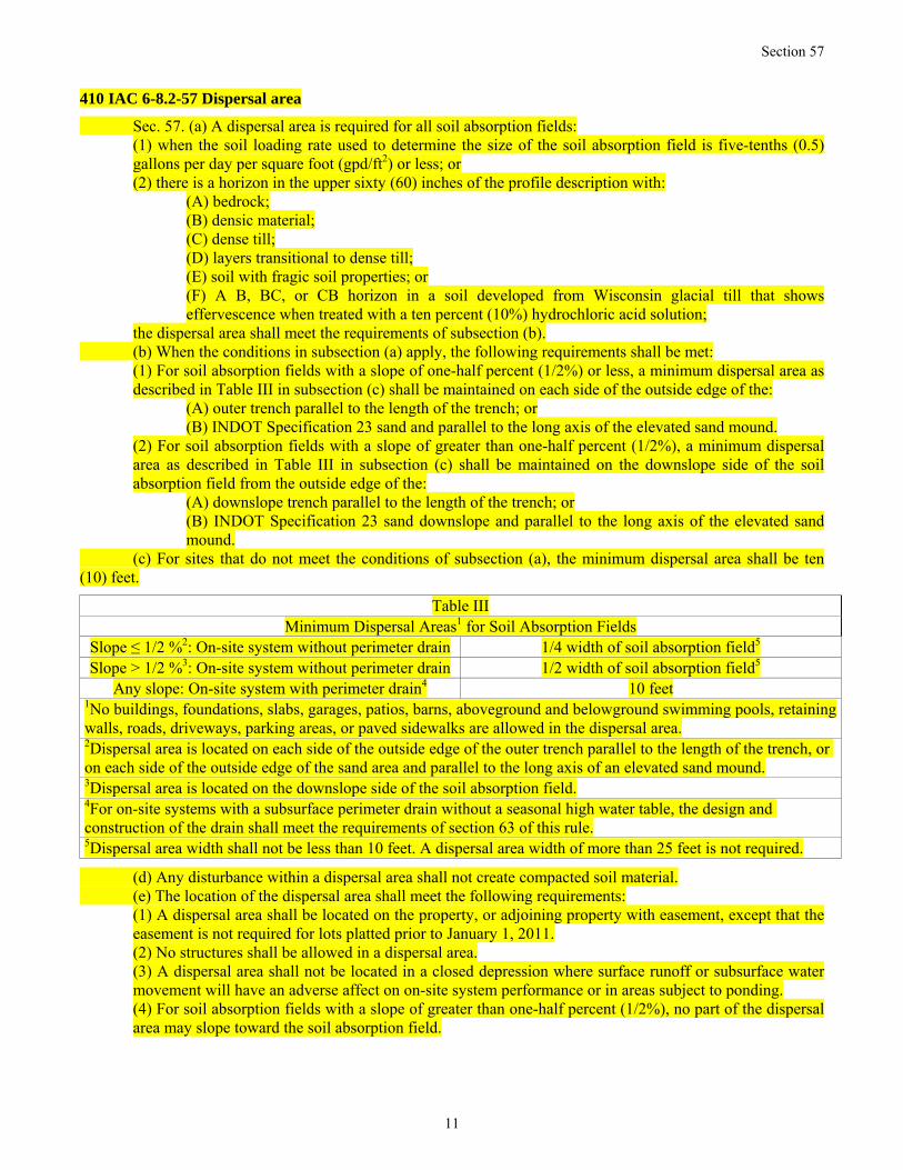
Table III Minimum Dispersal Areas1 for Soil Absorption Fields
Slope ≤ 1/2 %2: On-site system without perimeter drain 1/4 width of soil absorption field5 Slope > 1/2 %3: On-site system without perimeter drain 1/2 width of soil absorption field5
Any slope: On-site system with perimeter drain4 10 feet 1No buildings, foundations, slabs, garages, patios, barns, aboveground and belowground swimming pools, retaining walls, roads, driveways, parking areas, or paved sidewalks are allowed in the dispersal area. 2Dispersal area is located on each side of the outside edge of the outer trench parallel to the length of the trench, or on each side of the outside edge of the sand area and parallel to the long axis of an elevated sand mound. 3Dispersal area is located on the downslope side of the soil absorption field. 4For on-site systems with a subsurface perimeter drain without a seasonal high water table, the design and construction of the drain shall meet the requirements of section 63 of this rule. 5Dispersal area width shall not be less than 10 feet. A dispersal area width of more than 25 feet is not required.
(d) Any disturbance within a dispersal area shall not create compacted soil material. (e) The location of the dispersal area shall meet the following requirements:
(1) A dispersal area shall be located on the property, or adjoining property with easement, except that the easement is not required for lots platted prior to January 1, 2011. (2) No structures shall be allowed in a dispersal area. (3) A dispersal area shall not be located in a closed depression where surface runoff or subsurface water movement will have an adverse affect on on-site system performance or in areas subject to ponding. (4) For soil absorption fields with a slope of greater than one-half percent (1/2%), no part of the dispersal area may slope toward the soil absorption field.
11
Section 58
410 IAC 6-8.2-58 Septic tanks; general requirements Sec. 58. (a) Septic tanks shall be:
(1) watertight and constructed of durable material such as concrete, fiberglass, or polyethylene; and (2) protected from corrosion.
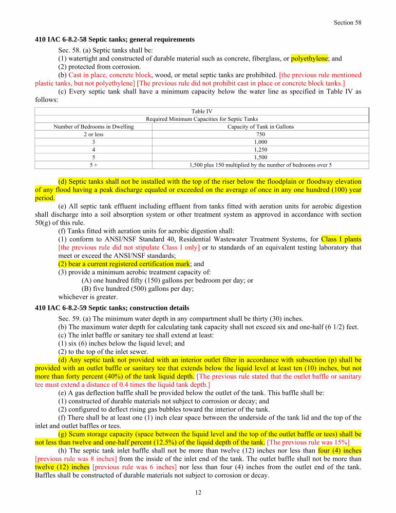
(b) Cast in place, concrete block, wood, or metal septic tanks are prohibited. [the previous rule mentioned plastic tanks, but not polyethylene] [The previous rule did not prohibit cast in place or concrete block tanks.] (c) Every septic tank shall have a minimum capacity below the water line as specified in Table IV as follows:
Table IV Required Minimum Capacities for Septic Tanks
Number of Bedrooms in Dwelling Capacity of Tank in Gallons 2 or less 750
3 1,000 4 1,250 5 1,500
5 + 1,500 plus 150 multiplied by the number of bedrooms over 5 (d) Septic tanks shall not be installed with the top of the riser below the floodplain or floodway elevation of any flood having a peak discharge equaled or exceeded on the average of once in any one hundred (100) year period. (e) All septic tank effluent including effluent from tanks fitted with aeration units for aerobic digestion shall discharge into a soil absorption system or other treatment system as approved in accordance with section 50(g) of this rule. (f) Tanks fitted with aeration units for aerobic digestion shall:
(1) conform to ANSI/NSF Standard 40, Residential Wastewater Treatment Systems, for Class I plants [the previous rule did not stipulate Class I only] or to standards of an equivalent testing laboratory that meet or exceed the ANSI/NSF standards; (2) bear a current registered certification mark; and (3) provide a minimum aerobic treatment capacity of:
(A) one hundred fifty (150) gallons per bedroom per day; or (B) five hundred (500) gallons per day;
whichever is greater. 410 IAC 6-8.2-59 Septic tanks; construction details Sec. 59. (a) The minimum water depth in any compartment shall be thirty (30) inches. (b) The maximum water depth for calculating tank capacity shall not exceed six and one-half (6 1/2) feet. (c) The inlet baffle or sanitary tee shall extend at least:
(1) six (6) inches below the liquid level; and (2) to the top of the inlet sewer.
(d) Any septic tank not provided with an interior outlet filter in accordance with subsection (p) shall be provided with an outlet baffle or sanitary tee that extends below the liquid level at least ten (10) inches, but not more than forty percent (40%) of the tank liquid depth. [The previous rule stated that the outlet baffle or sanitary tee must extend a distance of 0.4 times the liquid tank depth.] (e) A gas deflection baffle shall be provided below the outlet of the tank. This baffle shall be:
(1) constructed of durable materials not subject to corrosion or decay; and (2) configured to deflect rising gas bubbles toward the interior of the tank.
(f) There shall be at least one (1) inch clear space between the underside of the tank lid and the top of the inlet and outlet baffles or tees. (g) Scum storage capacity (space between the liquid level and the top of the outlet baffle or tees) shall be not less than twelve and one-half percent (12.5%) of the liquid depth of the tank. [The previous rule was 15%] (h) The septic tank inlet baffle shall not be more than twelve (12) inches nor less than four (4) inches [previous rule was 8 inches] from the inside of the inlet end of the tank. The outlet baffle shall not be more than twelve (12) inches [previous rule was 6 inches] nor less than four (4) inches from the outlet end of the tank. Baffles shall be constructed of durable materials not subject to corrosion or decay.
12

Section 59(i)
(i) The bottom of the tank inlet shall not be less than two (2) inches nor more than four (4) inches above the liquid level. [previous rule was “not less than 3 inches above the flow line of the outlet”] (j) Reinforced concrete septic tanks shall be constructed of concrete with a compressive strength of four thousand (4,000) pounds per square inch or greater. [previous rule required 4,000 psi concrete only when the wall was less than 4 inches thick] (k) Concrete septic tank walls shall be at least two and one-half (2 1/2) inches or greater in thickness. The design must allow at least one (1) inch cover over reinforcing steel or welded wire fabric. (l) Concrete septic tank bottoms shall conform to the specifications set forth for septic tank walls. (m) Concrete septic tank tops shall be a minimum of four (4) inches in thickness and reinforced with one-fourth (1/4) inch reinforcing rods in a six (6) inch grid or equivalent. (n) All septic tanks shall meet the following access opening requirements:
(1) At least one (1) opening eighteen (18) inches in minimum dimension per compartment for pumping access. (2) An access opening shall be located over each of the following:
(A) The inlet. (B) The outlet. (C) The sanitary tee or baffle, if present, on the partition or divider wall of a two-compartment tank.
(3) All access openings shall be positioned in such a way as to allow for maintenance, cleaning, and servicing of septic tanks and outlet filters. (4) When the top of the septic tank is installed at or above grade, all access openings shall be fitted with watertight, securely fastened covers. (5) All access openings for septic tanks shall also comply with the requirements of IC 16-41-25-3.
(o) All septic tanks shall meet the following riser requirements: (1) Risers and riser covers shall be made of corrosion resistant materials and withstand design external loads. (2) The lower section of the riser assembly shall be:
(A) cast into the tank lid; or (B) sealed to the lid with butyl sealant meeting ASTM C 990-09 to provide a watertight seal.
Joints between riser sections shall be sealed watertight. (3) When the top of the septic tank is installed below grade, risers shall:
(A) be installed over access openings used for pumping and for maintenance of the outlet filter; (B) extend to or above final grade; [previous rule requires minimum 8 inch diameter] (C) be fitted with a watertight cover securely fastened to the riser; and (D) comply with the requirements of IC 16-41-25-3.
(p) All septic tanks shall meet the following outlet filter requirements: (1) An outlet filter shall be installed in the septic tank of new on-site systems and existing on-site systems requiring a new septic tank. (2) Outlet filters shall:
(A) conform to ANSI/NSF Standard 46, Evaluation of Components and Devices Used in Wastewater Treatment Systems, maintain a current product listing with an ANSI accredited third-party certifier, and bear a listing mark; and (B) be rated by the manufacturer with a daily flow rate of one and one-half (1 1/2) times the total required septic tank capacity; or (C) be approved by the department.
(3) For on-site systems requiring repair, or soil absorption fields requiring replacement, the local health department may require an outlet filter. (4) Outlet filters shall be located in:
(A) a single septic tank when not used in series; (B) the second compartment of two-compartment tanks; (C) the last compartment of the last tank when two (2) or more tanks are used in series; or (D) a secondary watertight structure located after the last septic tank.
13

Section 59(p)(5)
(5) The outlet filter housing shall: (A) provide a minimum scum space of six (6) inches; and (B) include a gas deflection device.
(6) Outlet filters shall be: (A) installed according to manufacturer's recommendations; (B) placed to allow accessibility for routine maintenance without entering the tank or outlet structure if separate from the tank; and (C) maintained by the owner or agent and remain in service for the life of the septic tank.
(7) Service shall be performed as required, but no less than each time the septic tank is pumped and cleaned. (8) Outlet filters shall be located so they do not interfere with pumping and cleaning of the septic tank.
410 IAC 6-8.2-60 Septic tanks; installation and maintenance
Sec. 60. (a) Tanks shall be installed level on: (1) undisturbed soil; (2) sand; (3) aggregate no larger than one and one-half (1 1/2) inches in diameter; or (4) an engineered base.
(b) All drain holes shall be: (1) fitted with a threaded fitting, cast in place, shall be plugged, with a threaded plug; (2) plugged with an expandable pipe plug with a wing nut; or (3) plugged according to the septic tank manufacturer's recommendations.
(c) Connectors for tanks shall meet the following requirements: (1) Each pipe penetration shall be sealed with a flexible, watertight connector. (2) Precast concrete tanks shall use cast in place connectors conforming to ASTM C 1644-06 - Standard Specification for Resilient Connectors Between Reinforced Concrete On-Site Wastewater Tanks and Pipes. (3) Tanks made of materials other than precast concrete shall use flexible, watertight connectors that have been tested to, and have demonstrated conformance with, the performance requirements of ASTM C 1644-06, paragraph 7 - Test Methods and Requirements.
(d) All joints in the sewer connecting septic tanks in series shall be watertight.
410 IAC 6-8.2-61 Gravity distribution of effluent; distribution boxes
Sec. 61. (a) For gravity distribution of effluent, a distribution box or series of distribution boxes shall be installed between the septic tank and the subsurface absorption system, and each absorption line shall connect directly thereto. (b) Concrete distribution boxes shall be constructed of concrete with a compressive strength of four thousand (4,000) pounds per square inch or greater. Other materials may be considered on a case-by-case basis. [Previous rule was 3,000 psi] All materials must:
(1) be resistant to corrosion and decay; and (2) have sufficient structural strength to contain sewage and resist lateral compressive and bearing loads.
The minimum interior width of a distribution box shall be twelve (12) inches. The distribution box shall be fitted with a watertight, removable lid for access. (c) Each distribution box shall be designed to split the effluent flow equally among the effluent ports. All effluent ports shall be:
(1) at the same elevation; (2) of the same diameter; and (3) located at an elevation at least one (1) inch lower than the influent port.
The influent port shall be located or baffled to prevent unequal distribution of effluent to the distribution system. If baffles are provided, the baffles and their mounts or retainers shall provide a passageway for effluent between the box bottom and the bottom edge of the baffle of not more than two (2) inches. The baffle shall extend to one (1) inch above the top of the inlet. An elbow or sanitary tee in the vertical position may be used in place of a
14

Section 61(c)
baffle. The elbow must be a ninety (90) degree elbow and be turned down into the distribution box. The end of the elbow must be not more than two (2) inches above the bottom of the distribution box. The interior bottom of the distribution box shall be at least four (4) inches below the invert elevation of the effluent ports. A minimum of eight (8) inches freeboard above the invert elevation of the effluent port shall be provided. (d) Distribution boxes shall be installed level on either undisturbed soil, sand, sand mix, or aggregate no larger than one-half (1/2) inch in diameter, and the outlets shall be checked to assure that they are at a uniform elevation.
410 IAC 6-8.2-62 Piping
Sec. 62. (a) Piping used in a residential on-site sewage system shall meet or exceed the following applicable standards:
(1) Gravity sewer standards as follows: (A) The following for PVC piping:
(i) ASTM D 2665-09 for four (4) inch and six (6) inch pipe only. (ii) ASTM F 891-10 SDR 35 for four (4) inch through eight (8) inch cellular core pipe with minimum pipe stiffness of 50 (PS 50). (iii) ASTM D 3034-08 for the following:
(AA) SDR 26 and SDR 35 for four (4) inch through fifteen (15) inch pipe. (BB) SDR 26 with compression fittings for special crossings above or below potable water lines.
(B) The following for ABS piping: (i) ASTM D 2661-08 for four (4) inch and six (6) inch pipe only. (ii) ASTM D 2680-01(2009) for eight (8) inch through fifteen (15) inch pipe. (iii) ASTM D 2751-05 SDR 23.5 or SDR 35 for four (4) inch and six (6) inch pipe only.
(C) Waterworks grade ductile iron pipe with mechanical and tyton joints. (2) Pressure sewers, effluent force mains, and pressure distribution laterals as follows:
(A) The following for PVC piping: (i) ASTM D 2241-09 SDR 13.5, SDR 17, SDR 21, or SDR 26. (ii) ASTM D 1785-06 Schedule 40, 80, or 120.
(B) The following for ABS piping: (i) ASTM D 1527-99(2005) Schedule 40, 80 or 120, with solvent weld fittings. (ii) ASTM D 2282-99(2005) SDR 13.5, SDR 17, SDR 21, or SDR 26.
(b) Compression fittings must be used on pressure sewers when they are located ten (10) feet or less from a water line. (c) The residential sewer shall be a minimum of four (4) inches in diameter. Four (4) inch sewers shall be installed with a positive slope of not less than four (4) inches in twenty-five (25) feet and not more than thirty-six (36) inches in twenty-five (25) feet. Six (6) inch sewers, if utilized, shall be installed with a positive slope of not less than two (2) inches in twenty-five (25) feet and not more than thirty-six (36) inches in twenty-five (25) feet. A vertical drop may be installed in a residential sewer. Each vertical drop shall have a cleanout located immediately upslope. (d) Installation of effluent sewer pipe shall meet the following requirements:
(1) Effluent sewer pipe shall have a positive grade of at least two and four-tenths (2.4) inches per one hundred (100) feet or a grade of two-tenths percent (0.2%). (2) All joints shall be sealed according to the manufacturer's recommendations. (3) For installation prior to a distribution box, effluent sewer pipe shall be bedded according to manufacturer requirements and backfilled with debris-free soil material or aggregate without damaging the pipe. (4) For installation after a distribution box, effluent sewer pipe shall be stabilized, bedded, and backfilled without damaging the pipe with debris-free soil material to prevent the movement of effluent along the outside of the pipe. (5) The invert of each effluent sewer pipe that outlets from a distribution box shall be at the same elevation so that each gravity distribution lateral receives an equal volume of effluent.
15
Section 62(d)(6)
(6) Each effluent sewer from an outlet of a distribution box that directly serves a trench shall extend into the aggregate in the trench.
(e) Absorption field laterals standards are as follows: (1) Only:
(A) sewer pipe listed in subsection (a); (B) potable water pipe (four (4) inches or more in diameter); or (C) pipe meeting ASTM D 2729-03 or ASTM F 810-07;
is suitable for absorption field gravity laterals. (2) Gravity distribution lateral pipe shall meet the following requirements:
(A) Four (4) inch in diameter gravity sewer and effluent sewer pipe listed in subsection (a)(1). (B) Four (4) inch in diameter potable water pipe listed in subsection (a)(2). (C) Four (4) inch PVC ASTM D 2729-03. (D) Four (4) inch polyethylene ASTM F 810-07 or AASHTO M252 Type SP.
(3) Gravity distribution laterals shall have two (2) or three (3) rows of holes separated by one hundred twenty (120) degrees with five-eighths (5/8) inch or three-quarter (3/4) inch hole diameter with holes spaced at five (5) inches or less. (4) All joints and end caps shall be connected according to the manufacturer's recommendations. (5) The distal end of each gravity distribution lateral shall be capped. (6) For installation, gravity distribution laterals in aggregate trenches shall be installed level along their length:
(A) for two (2) hole gravity distribution laterals, the laterals shall be placed in the aggregate with the rows of holes located at one hundred twenty (120) and two hundred forty (240) degrees from vertical (rows of holes at 4 o'clock and 8 o'clock); and (B) for three (3) hole gravity distribution laterals, the laterals shall be placed in the aggregate with the rows of holes located at one hundred twenty (120), two hundred forty (240), and three hundred sixty (360) degrees from vertical (rows of holes at 4 o'clock, 8 o'clock, and 12 o'clock).
(f) Pipe for water table modification standards are as follows: (1) ASTM C 412-05a for concrete pipe. (2) ASTM C 4-04(2009) for vitrified pipe. (3) ASTM 498-95 for clay pipe. (4) The following for polyethylene pipe:
(A) ASTM F 405-05. (B) ASTM F 667-05. (C) NRCS 606.
410 IAC 6-8.2-63 Drainage
Sec. 63. (a) A surface diversion shall be constructed if drainage from an adjoining upslope landscape affects the soil absorption field site.
(1) A surface diversion shall: (A) have a positive grade of at least two and four-tenths (2.4) inches per one hundred (100) feet, or a grade of two-tenths percent (0.2%); and (B) be of sufficient depth and width to move surface water away from the soil absorption field.
(2) A surface diversion may be used in combination with an on-site subsurface drainage system. (b) When a subsurface drainage system is constructed to lower a perched or apparent seasonal high water table, the following shall apply:
(1) If the site has a slope of equal to or less than two percent (2%), the subsurface drain shall surround the on-site system. If the site slope exceeds two percent (2%), the subsurface drain may be constructed only on the upslope side of the on-site system. (2) If the seasonal high water table is perched, the subsurface drain trench shall be constructed at least two (2) inches into the massive clay, glacial till, or fragipan.
16
Section 63(b)(3)
(3) The subsurface drain pipe shall be: (A) at least four (4) inches in diameter; (B) slotted; and (C) when installed in:
(i) sands; (ii) loamy sands; (iii) sandy loams; (iv) fine sandy loams; (v) loams; (vi) silt loams; or (vii) silts;
wrapped with a geotextile fabric with an effective opening size no smaller than two-tenths (0.2) millimeter and no larger than eighty-five hundredths (0.85) millimeter.
(4) The subsurface drain trench shall: (A) have a positive slope of at least two-tenths (0.2) feet per one hundred (100) feet when a four (4) inch drain pipe is used; (B) have a positive slope of at least one-tenth (0.10) feet per one hundred (100) feet when a six (6) inch drain pipe is used; and (C) be constructed with no sags in the line.
(5) A subsurface drain trench installed upslope from a residential on-site sewage system shall be: (A) backfilled to final grade with aggregate which meets the minimum requirements of section 67 of this rule, washed aggregate with a gradation in the range of INDOT Specifications 8 through 11, INDOT Specification 23 sand or equivalent; or (B) filled to within six (6) inches of final grade aggregate which meets the minimum requirements of section 67 of this rule, with washed aggregate with a gradation in the range of INDOT Specifications 8 through 11, INDOT Specification 23 sand or equivalent and the final six (6) inches to final grade with cover soil material.
(6) Subsurface drain trench installed on sides or downslope, and segment drain trenches may be: (A) backfilled to final grade with aggregate which meets the minimum requirements of section 67 of this rule, washed aggregate with a gradation in the range of INDOT Specifications 8 through 11, INDOT Specification 23 sand or equivalent; or (B) filled to within six (6) inches of final grade with aggregate which meets the minimum requirements of section 67 of this rule, washed aggregate with a gradation in the range of INDOT Specifications 8 through 11, INDOT Specification 23 sand or equivalent and the final six (6) inches to final grade with cover soil material.
(7) When INDOT Specification 23 sand is used for backfill, the drainpipe shall be wrapped with a geotextile fabric. (8) The aggregate used as backfill in the perimeter, interceptor, or segment drain trenches described in subdivisions (5)(B) and (6)(B) shall be covered with a geotextile fabric barrier which meets the minimum requirements in section 66 of this rule, in such a manner as to prevent the aggregate from becoming clogged with the earth fill. (9) The subsurface drain trench and the associated discharge piping shall be constructed to permit water to flow by gravity throughout its length. No pumps or siphons shall be utilized to effect the movement of the collected water.
(c) When a subsurface drain is provided, it shall be sufficiently deep to lower the seasonal water. When the drain cannot be constructed at least two (2) inches into the massive clay, glacial till, or fragipan, the depth of the drain shall be the following unless calculations are used to determine drain depth:
(1) For trench on-site systems, the invert elevation of the subsurface perimeter, interceptor, or segment drain shall be at least thirty-six (36) inches below the elevation of any adjacent soil absorption trench bottom. (2) For elevated sand mound on-site systems, the invert elevation of the subsurface perimeter or interceptor drain shall be at least thirty-two (32) inches below existing grade.
17
Section 63(d)
(d) On-site subsurface drainage systems shall be located at soil absorption field sites as follows: (1) All portions of an on-site subsurface drainage system shall be installed at least ten (10) feet from the outside edge of any soil absorption trench. (2) All portions of an on-site subsurface drainage system shall be installed at least ten (10) feet from the outside edge of the INDOT Specification 23 sand. (3) Spacing of subsurface perimeter drains and segment drains installed parallel to the long axis of a soil absorption field must be less than or equal to sixty-five (65) feet, unless a greater spacing is determined through calculations.
(e) The subsurface drain shall not cross any portion of the soil absorption system. (f) Tile outlets shall be provided with rodent guards. 410 IAC 6-8.2-64 Dosing tanks Sec. 64. (a) Dosing tanks:
(1) must be watertight and constructed of durable material such as concrete, fiberglass, or plastic; and (2) shall be protected from corrosion.
(b) Cast in place, concrete block, wood, or metal dosing tanks are prohibited. [Cast in place and concrete block tanks were permitted in the previous rule] (c) Reinforced concrete dosing tanks shall be constructed of concrete with a compressive strength of four thousand (4,000) pounds per square inch or greater. [Previously 4,000 psi concrete when the wall < 4” thick] (d) Concrete dosing tank walls shall be at least two and one-half (2 1/2) inches or greater in thickness. The design shall allow at least one (1) inch cover over reinforcing steel or welded wire fabric. (e) The required liquid holding capacity of the dosing tank shall not be considered as any portion of the required liquid volume of the septic tank. (f) The liquid holding capacity of a dosing tank must equal the dose volume required by this rule for each type of soil absorption field, in addition to the volume of liquid that will drain back from any pressure sewer when pumping ceases. [Previous rule: liquid holding capacity to = the daily average wastewater flow + drainback] Additional capacity must be provided to:
(1) keep the dosing tank effluent pump submerged at all times; and (2) provide sufficient freeboard for a high water alarm.
(g) Each dosing tank shall be fitted with an effluent pump sized in conformance with section 65, 73(u), 75(t), or 75(dd) of this rule, with controls, and with a high water alarm switch set at a level above the design high water mark. The alarm shall:
(1) be on a separate circuit from the effluent pump; and (2) include an audible and visible alarm.
(h) Switches that are comparable to mercury float level switches shall be used for dosing tank effluent pump start and stop controls and for high water alarms. (i) Dosing tanks shall be provided with access ports extending to the ground surface that are sufficiently large to allow access to maintain the tank and effluent pumps. Safely secured, gastight covers shall be provided for each required access port. (j) Dosing tanks shall not be installed with the top of the riser below the floodplain or floodway elevation of any flood having a peak discharge equaled or exceeded on the average of once in any one hundred (100) year period. 410 IAC 6-8.2-65 Effluent pumps Sec. 65. (a) All effluent pumps shall be:
(1) submersible pumps suitable for use in a corrosive atmosphere; (2) sized to deliver the total design flow rate while meeting the total dynamic head requirements of the system; (3) connected to pump discharge piping that is adequately secured; and (4) installed in such a manner as to allow for removal without entering the dosing tank or dewatering the dosing tank.
(b) Effluent pumps shall be provided with a suitable means of quick, convenient disconnection from the discharge piping:
(1) Fittings and valves shall be of compatible corrosion resistant material. (2) A quick disconnect union, breakaway flange, or similar disconnect device shall be provided in each pump discharge pipe.
18
Section 65(b)(3)
(3) Submersible pumps shall be provided with a corrosion resistant lifting rope or chain to facilitate removal of the pump. (4) Quick disconnect unions and valves shall be readily available from the ground surface without entering the tank. [The specific requirement for breakaway flanges and lifting chains has been removed.]
(c) Controls other than liquid level sensors shall not be located within the dosing tank. (d) The junction box located in the dose tank riser shall be rated as a NEMA 4X, National Electrical Manufacturers Association, NEMA 250-2003. All connectors to the junction box shall form a watertight seal:
(1) to the junction box; and (2) between connector openings and incoming wires.
(e) Any connector not used for wiring shall be fitted with a watertight plug.
410 IAC 6-8.2-66 Barrier materials
Sec. 66. (a) Barrier material shall meet the following requirements: (1) Be synthetic fabric, either spun bonded or woven. (2) Have the following physical characteristics:
(A) A weight equal to or greater than three and one-tenth (3.1) ounces per square yard. (B) A grab tensile strength equal to or greater than eighty (80) pounds. (C) A grab tensile elongation less than or equal to fifty percent (50%). (D) A trapezoid tear strength equal to or greater than thirty (30) pounds. (E) A puncture resistance equal to or greater than thirty (30) pounds. (F) A Mullen Burst equal to or greater than one hundred forty-five (145) pounds per square inch. (G) A permittivity of less than or equal to 2.2 sec-1. (H) A water flow rate less than or equal to one hundred fifty (150) gallons per minute per square foot. (I) A UV resistance at five hundred (500) hours equal to or greater than seventy percent (70%) strength retained.
(3) Have the following chemical characteristics: (A) Be nonbiodegradable. (B) Be resistant to acids and alkalies within a pH range of 4 to 10. (C) Be resistant to common solvents.
(b) Installation of barrier material shall meet the following requirements: (1) For aggregate trenches and elevated sand mound aggregate beds, barrier material shall be placed on the aggregate to prevent soil particle movement into the aggregate. (2) The barrier material shall cover the aggregate of aggregate trenches and elevated sand mound aggregate beds from side to side and from end to end.
410 IAC 6-8.2-67 Aggregate
Sec. 67. (a) Aggregate to be used in absorption systems shall be gravel, stone, or other approved materials. Crushed limestone aggregate, if used, shall be rated as forty percent (40%) or less on the Los Angeles abrasion quality requirement of the INDOT 1999 Standard Specifications. [Previous rule referenced Moh’s scale of hardness] (b) Aggregate shall be a mixture with no aggregate smaller in size than one-half (1/2) inch in diameter nor any aggregate larger than two and one-half (2 1/2) inches in diameter. The aggregate must be larger than the openings in the laterals. Fines, sand, and clay shall be removed from the aggregate prior to its placement in the trench. (c) Tire chips may be used in place of stone for soil absorption fields on a one-for-one basis, volumetrically. Tire chips used for soil absorption fields must have a nominal size of two (2) inches with chip dimensions being no less than one-half (1/2) inch and no greater than four (4) inches. The local health department shall:
(1) maintain an inventory of on-site systems installed using tire chips; and (2) provide that information to the department upon request.
When construction permits are issued for on-site systems that incorporate tire chips, they should note in writing that tire chips will be utilized and should include requirements for nominal tire chip size and removal of fines. Tire chips will have protruding wires and shall be removed from the ground surface during site clean-up.
19
Section 68
410 IAC 6-8.2-68 On-site evaluation
Sec. 68. (a) Before issuance of any permit for construction of a residential on-site sewage system or the replacement or alteration of a soil absorption field, an on-site evaluation, which shall include an evaluation of the soil profile, shall be conducted. On-site system feasibility, location, selection, and design shall be based on the site evaluation and information obtained from the soil profile. The site and soil information needed is outlined and further defined in subsection (e). Properties of the soil at each site shall be determined using the guidelines set forth in the soil manuals, technical bulletins, and handbooks of the NRCS. The local health department may, when necessary, provide or require to be provided a direct soil profile observation by a soil scientist, using the guidelines set forth in the soil manuals, technical bulletins, and handbooks of the NRCS. (b) When direct soil profile observations are made, soil profile information shall be recorded:
(1) to a depth of five (5) feet; or (2) until a layer is encountered that cannot be readily penetrated;
whichever is shallower. (c) The on-site evaluation shall be conducted before construction begins. No construction on the residential on-site sewage system may take place if the residential on-site sewage system site is disturbed or altered after the on-site evaluation by the addition of fill material (other than construction necessary for the residential on-site sewage system) or by cutting, scraping, compaction, or the removal of soil, until a new evaluation has been conducted and a modified construction permit has been issued. (d) When any site limitations and soil information for the site has been thusly determined, the owner is responsible for the residential on-site sewage system design that:
(1) addresses the demands of the site in accordance with this rule; and (2) will meet local health department approval.
(e) The information needed to evaluate a site includes the following: (1) Topographic information including the following:
(A) The slope and slope aspect. (B) Surface drainage characteristics and patterns including swales, ditches, and streams. (C) The proposed or existing location of house and well. (D) The location of other major features or structures. (E) The location of soil evaluation sites and appropriate soil type boundaries. (F) The topographic position of the site.
(2) Soil characteristics as follows: (A) The approximate depths of soil horizons. (B) The soil color, structure, and texture at each horizon. (C) The depth to any layer that has a soil loading rate greater than seventy-five hundredths (0.75) gallons per day per square foot or less than twenty-five hundredths (0.25) gallons per day per square foot. (D) The depth to seasonal high ground water as indicated by soil wetness characteristics. (E) The depth to bedrock. (F) The soil consistence at each horizon. (G) The soil effervescence at each horizon. (H) The presence or absence of roots.
(f) Soil absorption systems shall not be constructed as follows: (1) In areas where surface drainage or runoff will have an adverse effect on the on-site system, unless the surface runoff can be effectively diverted around the on-site system. (2) Below the floodplain or floodway elevation of any flood having a peak discharge equaled or exceeded on the average of once in any one hundred (100) year period. (3) In areas subject to ponding.
20

Section 69
410 IAC 6-8.2-69 Subsurface system selection criteria
Sec. 69. Subsurface soil absorption systems are the systems of choice. All of the following site conditions in this section must be met if subsurface soil absorption systems are to be constructed:
(1) Sufficient area exists on the lot for an appropriately sized system, while meeting the separation distances of section 56 of this rule and the dispersal area requirements of section 57 of this rule. (2) The site has a slope of fifteen percent (15%) or less. (3) The topographic position of the site on which the system is to be built is convex, hill slope, or flat. If surface and subsurface drainage can be diverted around the site, a toe slope position can be utilized. (4) All soil horizons at the site from the ground surface to twenty-four (24) inches below the proposed trench bottom have a soil loading rate of not less than twenty-five hundredths (0.25) and not more than one and twenty-hundredths (1.20) gallons per day per square foot as determined from Table V, as follows:
Table V Soil Loading Rates for Subsurface Systems (in gpd/ft2)
SOIL STRUCTURE CLASSES
SOIL TEXTURE CLASSES
Single Grain
Granular Platy*
Strong: Angular,
Subangular Blocky
Moderate: Angular,
Subangular Blocky
Prismatic, or Weak: Angular,
Subangular Blocky
Fragic Characteristics:
Very Coarse Prismatic
Structureless, Massive,
Friable, V. Friable
Structureless, Massive, Compact,
Firm, V. Firm
Gravel, Coarse Sand >1.2 N/A N/A N/A N/A N/A N/A N/A Loamy Coarse Sand, Medium Sand 1.20 1.20 N/A N/A 1.20 N/A N/A N/A
Fine Sand, Loamy Sand, Loamy Fine Sand
0.75 0.60 N/A 0.75 0.75 N/A 0.75 N/A
Very Fine Sand, Loamy V. Fine Sand
0.50 0.50 N/A 0.75 0.60 N/A 0.60 N/A
Sandy Loam, Coarse Sandy Loam N/A 0.75 N/A 0.60 0.60 0.00 0.60 0.00
Fine Sandy Loam, V. Fine Sandy Loam
N/A 0.75 N/A 0.60 0.60 0.00 0.60 0.00
Loam N/A 0.75 0.75 0.50 0.50 0.00 0.50 0.00 Silt Loam, Silt N/A 0.75 0.75 0.50 0.30 0.00 0.30 0.00 Sandy Clay Loam N/A 0.60 0.60 0.50 0.30 0.00 0.30 0.00 Silty Clay Loam, Clay Loam, Sandy Clay
N/A 0.60 0.60 0.30 0.25 0.00 0.25 0.00
Silty Clay, Clay N/A 0.60 0.50 0.30 0.25 N/A 0.25 0.00 Organic Soil Materials N/A N/A N/A N/A N/A N/A 0.00 N/A
Limnic Soil Materials N/A N/A N/A N/A N/A N/A N/A 0.00
Bedrock N/A N/A N/A N/A N/A N/A N/A N/A N/A NOT APPLICABLE *Except where platy structure has been caused by soil compaction. Platy structure caused by compaction has a soil loading rate of 0.00 gpd/ft.2
(5) When coarse fragments (particles greater than two (2) mm) of greater than thirty-five percent (35%) by volume are described in the soil profile analysis, all soil horizons at the site from the ground surface to twenty-four (24) inches below the proposed trench bottom, the soil fraction that is less than two (2) mm in size must be:
21 (A) a texture finer than loamy sand; and
Section 69(6)
22
(B) less than 35 percent (35%) clay content by volume (6) When no B, BC, or CB horizon from the ground surface to twenty-four (24) inches below the proposed trench bottom in a soil developed from Wisconsin glacial till shows effervescence when treated with a ten percent (10%) hydrochloric acid solution. (7) Any seasonal high water table at the site of the proposed system can be lowered to thirty-four (34) inches or more below the surface, in accordance with section 63 of this rule. (8) Site conditions must permit distribution of effluent to each trench of the system so that each square foot of absorptive area can be loaded with an equal volume of effluent.
410 IAC 6-8.2-70 Subsurface system type selection criteria
Sec. 70. (a) A subsurface gravity feed system may be constructed if the: (1) DDF of the project is equal to or greater than four hundred fifty (450) gallons per day; (2) soil loading rate of the site is equal to or greater than twenty-five hundredths (0.25) gallons per day per square foot and equal to or less than seventy-five hundredths (0.75) gallons per day per square foot, as determined from Table V in section 69(4) of this rule; (3) trench bottom will be at least thirty (30) inches above any horizon with a soil loading rate less than twenty-five hundredths (0.25) gallons per day per square foot; and (4) absorption field, including either half of an alternating field, is designed with a total absorption trench length that does not exceed five hundred (500) lineal feet.
(b) A subsurface gravity feed system may also be constructed if the: (1) DDF of the proposed system is less than four hundred fifty (450) gallons per day; (2) site has a soil loading rate of equal to or greater than twenty-five hundredths (0.25) gallons per day per square foot and equal to or less than seventy-five hundredths (0.75) gallons per day per square foot, as determined from Table V in section 69(4) of this rule; (3) trench bottom will be at least twenty-four (24) inches above any horizon with a soil loading rate less than twenty-five hundredths (0.25) gallons per day per square foot; and (4) absorption field, including either half of an alternating field, is designed with a total absorption trench length that does not exceed five hundred (500) lineal feet.
(c) A subsurface gravity feed system that utilizes alternating fields or is dosed using pump assisted distribution may be constructed if the:
(1) soil loading rate of the site is equal to or greater than twenty-five hundredths (0.25) gallons per day per square foot and equal to or less than seventy-five hundredths (0.75) gallons per day per square foot, as determined from Table V in section 69(4) of this rule; and (2) trench bottom will be at least twenty-four (24) inches above any horizon with a soil loading rate less than twenty-five hundredths (0.25) gallons per day per square foot.
(d) If any soil absorption field, including either half of an alternating field, is designed with a total absorption trench length greater than five hundred (500) lineal feet, the absorption field shall be dosed using pump assisted distribution. (e) If any soil horizon within twenty-four (24) inches of the proposed trench bottom has a soil loading rate of one and twenty-hundredths (1.20) gallons per day per square foot as determined from Table V in section 69(4) of this rule, the subsurface soil absorption system shall utilize pressure distribution.
410 IAC 6-8.2-71 Elevated system selection criteria
Sec. 71. Elevated sand mound systems may be constructed if the following site conditions are met: (1) Sufficient area exists on the lot for an appropriately sized system, while meeting the separation distances of section 56 of this rule and the dispersal area requirements of section 57 of this rule. (2) The site on which the system is to be built has a slope of six percent (6%) or less. (3) The topographic position of the site on which the system is to be built is convex, hill slope, or flat. If surface and subsurface drainage can be diverted around the site, a toe slope position can be utilized.
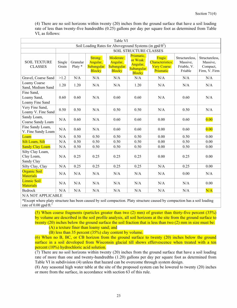
Section 71(4)
(4) There are no soil horizons within twenty (20) inches from the ground surface that have a soil loading rate of less than twenty-five hundredths (0.25) gallons per day per square foot as determined from Table VI, as follows:
Table VI Soil Loading Rates for Aboveground Systems (in gpd/ft2)
SOIL STRUCTURE CLASSES
SOIL TEXTURE CLASSES
Single Grain
Granular Platy *
Strong: Angular,
Subangular Blocky
Moderate: Angular,
Subangular Blocky
Prismatic, or Weak: Angular,
Subangular Blocky
Fragic Characteristics:
Very Coarse Prismatic
Structureless, Massive,
Friable, V. Friable
Structureless, Massive, Compact,
Firm, V. Firm
Gravel, Coarse Sand >1.2 N/A N/A N/A N/A N/A N/A N/A Loamy Coarse Sand, Medium Sand 1.20 1.20 N/A N/A 1.20 N/A N/A N/A
Fine Sand, Loamy Sand, Loamy Fine Sand
0.60 0.60 N/A 0.60 0.60 N/A 0.60 N/A
Very Fine Sand, Loamy V. Fine Sand 0.50 0.50 N/A 0.50 0.50 N/A 0.50 N/A
Sandy Loam, Coarse Sandy Loam N/A 0.60 N/A 0.60 0.60 0.00 0.60 0.00
Fine Sandy Loam, V. Fine Sandy Loam N/A 0.60 N/A 0.60 0.60 0.00 0.60 0.00
Loam N/A 0.50 0.50 0.50 0.50 0.00 0.50 0.00 Silt Loam, Silt N/A 0.50 0.50 0.50 0.50 0.00 0.50 0.00 Sandy Clay Loam N/A 0.50 0.50 0.50 0.50 0.00 0.50 0.00 Silty Clay Loam, Clay Loam, Sandy Clay
N/A 0.25 0.25 0.25 0.25 0.00 0.25 0.00
Silty Clay, Clay N/A 0.25 0.25 0.25 0.25 N/A 0.25 0.00 Organic Soil Materials N/A N/A N/A N/A N/A N/A 0.00 N/A
Limnic Soil Materials N/A N/A N/A N/A N/A N/A N/A 0.00
Bedrock N/A N/A N/A N/A N/A N/A N/A N/A N/A NOT APPLICABLE *Except where platy structure has been caused by soil compaction. Platy structure caused by compaction has a soil loading rate of 0.00 gpd/ft.2
(5) When coarse fragments (particles greater than two (2) mm) of greater than thirty-five percent (35%) by volume are described in the soil profile analysis, all soil horizons at the site from the ground surface to twenty (20) inches below the ground surface the soil fraction that is less than two (2) mm in size must be:
(A) a texture finer than loamy sand; and (B) less than 35 percent (35%) clay content by volume.
(6) When no B, BC, or CB horizon from the ground surface to twenty (20) inches below the ground surface in a soil developed from Wisconsin glacial till shows effervescence when treated with a ten percent (10%) hydrochloric acid solution. (7) There are no soil horizons within twenty (20) inches from the ground surface that have a soil loading rate of more than one and twenty-hundredths (1.20) gallons per day per square foot as determined from Table VI in subdivision (4) unless that hazard can be overcome through system design. (8) Any seasonal high water table at the site of the proposed system can be lowered to twenty (20) inches or more from the surface, in accordance with section 63 of this rule.
23

Section 72
410 IAC 6-8.2-72 Subsurface gravity feed systems; construction requirements
Sec. 72. (a) The minimum absorption area (in square feet) required for each gravity feed subsurface soil absorption system shall be based on the following:
(1) The number of bedrooms and bedroom equivalents in the dwelling. (2) The appropriate soil loading rate (in gallons per day per square foot) determined from Table V in section 69(4) of this rule. (3) The vertical separation distance between the bottom of the proposed trench and any soil layer with a soil loading rate of less than twenty-five hundredths (0.25) gallons per day per square foot. The soil loading rate used for this computation shall be the soil loading rate of the most restrictive horizon in the first twenty-four (24) inches below the trench bottom. (4) The absorption area shall be computed using the following formula:
Area = 150 g × number of bedrooms and bedroom equivalents
Soil loading rate in gpd/sq. ft. [The SAF reduction on depth of suitable soil has been removed.]
(b) All gravity feed subsurface soil absorption systems shall be located in accordance with the separation distances shown in Table II in section 56(a) of this rule. Gravity feed subsurface soil absorption systems shall not be constructed where there exist horizons, layers, or strata within thirty-four (34) inches of the ground surface with a soil loading rate less than twenty-five hundredths (0.25) gallons per day per square foot or greater than seventy-five hundredths (0.75) gallons per day per square foot as determined from Table V in section 69(4) of this rule. (c) Soil absorption systems shall not be wholly or partly located in a drainage way subject to intermittent flooding. (d) In order to provide equal flow distribution in gravity feed subsurface soil absorption systems, each absorption trench must be individually connected to a distribution box by at least five (5) feet of unperforated pipe that is laid with a gravel free backfill. All absorption trenches served by a common distribution box must be constructed so that each square foot of the absorptive area served by the distribution box is loaded with an equal volume of effluent. The distal ends on the distribution laterals may be manifolded together by piping on sites with slopes of two percent (2%) or less, but shall not be tied together on sites with slopes of greater than two percent (2%). When the distal ends of the absorption trenches are manifolded, the manifold trench area shall not count as meeting any of the minimum absorption area required by subsection (a)(4). (e) Each trench and distribution lateral in a gravity feed subsurface soil absorption system shall be uniformly level throughout its length. (f) No single absorption trench in a gravity feed subsurface soil absorption system shall exceed one hundred (100) feet in length. (g) On sloping sites, absorption trenches of a gravity feed soil absorption system shall be constructed along the contour. (h) There shall be a minimum separation of seven and one-half (7 1/2) feet, on center, between absorption field trenches, measured perpendicular to the trenches. (i) All gravity feed subsurface soil absorption fields shall be designed to utilize trenches with a minimum width of eighteen (18) inches and a maximum trench width of thirty-six (36) inches. (j) The minimum depth from original grade to the bottom of a trench of a gravity feed subsurface soil absorption system shall not be less than ten (10) inches, and the maximum depth to the bottom of a trench of a gravity feed subsurface soil absorption system shall not be more than thirty-six (36) inches. (k) Perforated pipe distribution laterals in the absorption trench of a gravity feed subsurface soil absorption system shall be completely surrounded by aggregate that meets the specifications in section 67 of this rule. There shall be at least six (6) inches of aggregate below the pipe. (l) The minimum depth of aggregate above the distribution laterals shall be:
(1) two (2) inches throughout the entire length and width of trenches having a depth of twelve (12) inches or greater; or (2) two (2) inches above the distribution lateral for the entire length of trenches having a depth of ten (10) to twelve (12) inches.
24

Section 72(m)
(m) The aggregate used in a gravity feed subsurface soil absorption system shall be covered with a geotextile fabric barrier that meets the minimum requirements in section 66 of this rule, in such a manner as to prevent the aggregate from becoming clogged with the earth fill. [The use of straw has been removed.] (n) A minimum of twelve (12) inches of cover shall be provided over the aggregate in the trenches, and any fill required to provide cover shall be crowned over the entire field to promote surface runoff. (o) Subsurface soil absorption systems shall not be constructed in clayey soils during periods of wet weather when the soil is sufficiently wet at the depth of installation to exceed its plastic limit. This includes those soils classified as:
(1) sandy loam; (2) silt loam; (3) loam; (4) clay loam; (5) silty clay loam; (6) sandy clay; (7) silty clay; and (8) clay.
For the purpose of this rule, the plastic limit of a soil shall be considered to have been exceeded when the soil can be rolled between the palms of the hands to produce threads one-eighth (1/8) inch in diameter without breaking apart and crumbling. (p) Special caution shall be taken to prevent wheeled and tracked vehicles from compacting the area selected for placement of the absorption system before, during, and after construction of the trenches, especially during wet weather. Precaution is especially important where clayey soils are involved. This includes those soils classified as:
(1) sandy loam; (2) silt loam; (3) loam; (4) clay loam; (5) silty clay loam; (6) sandy clay; (7) silty clay; and (8) clay.
Alteration of soil structure by movement of vehicles may be grounds for rejection of the site or the system, or both. (q) Excessive smearing of the usable absorption trench sidewalls or bottom during construction may:
(1) result in irreversible damage to the soil infiltrative surface; and (2) be grounds for rejection of the site or the system, or both.
(r) Excessive vegetation at the soil absorption field site shall be cut and removed prior to installation without causing compacted soil material. (s) If trees are present within the proposed soil absorption field:
(1) soil absorption trenches may be routed around trees provided the trenches follow the contour of the site; or (2) tree stumps and root balls may be removed provided the resulting excavation will not exceed the permit requirements for width and depth of the soil absorption trench.
410 IAC 6-8.2-73 Subsurface gravity feed flood dosed systems
Sec. 73. (a) The minimum absorption area (in square feet) required for each gravity feed flood dosed subsurface soil absorption system shall be based on the following:
(1) The number of bedrooms and bedroom equivalents in the dwelling. (2) The appropriate soil loading rate (in gallons per day per square foot) determined from Table V in section 69(4) of this rule. (3) The vertical separation distance between the bottom of the proposed trench and any soil layer with a soil loading rate of less than twenty-five hundredths (0.25) gallons per day per square foot. The soil loading rate used for this computation shall be the soil loading rate of the most restrictive horizon in the first twenty-four (24) inches below the trench bottom.
25
Section 73(a)(4)
(4) The absorption area shall be computed using the following formula:
Area = 150 g × number of bedrooms and bedroom equivalents Soil loading rate in gpd/sq. ft.
[The SAF reduction on depth of suitable soil has been removed.] (b) All subsurface gravity feed flood dosed absorption systems shall be located in accordance with the
separation distances shown in Table II in section 56(a) of this rule. Subsurface gravity feed flood dosed soil absorption systems shall not be constructed where there exist horizons, layers, or strata within thirty-four (34) inches of the ground surface with a soil loading rate less than twenty-five hundredths (0.25) gallons per day per square foot or greater than seventy-five hundredths (0.75) gallons per day per square foot as determined from Table V in section 69(4) of this rule. (c) Subsurface gravity feed flood dosed soil absorption systems shall not be wholly or partly located in a drainage way subject to intermittent flooding. (d) In order to provide equal flow distribution in gravity feed flood dosed systems, each absorption trench must be individually connected to a distribution box by at least five (5) feet of unperforated pipe that is laid with a gravel free backfill. All absorption trenches served by a common distribution box must be constructed so that each square foot of the absorptive area served by the distribution box is loaded with an equal volume of effluent. (e) No single absorption trench shall exceed one hundred (100) feet in length. (f) On sloping sites, absorption trenches shall be constructed along the contour. (g) There shall be a minimum separation of seven and one-half (7 1/2) feet, on center, between absorption field trenches, measured perpendicular to the trenches. (h) All subsurface gravity feed flood dosed absorption fields shall be designed to utilize trenches with a minimum width of eighteen (18) inches and a maximum trench width of thirty-six (36) inches. (i) The minimum depth from original grade to the bottom of a subsurface gravity feed flood dosed absorption trench shall not be less than ten (10) inches, and the maximum depth to the bottom of the trench shall not be more than thirty-six (36) inches. (j) Perforated pipe distribution laterals in the subsurface gravity feed flood dosed soil absorption trench shall be completely surrounded by aggregate that meets the specifications in section 67 of this rule. There shall be at least six (6) inches of aggregate below the pipe. (k) The minimum depth of aggregate above the distribution laterals shall be:
(1) two (2) inches throughout the entire length and width of trenches having a depth of twelve (12) inches or greater; or (2) two (2) inches above the distribution lateral for the entire length of trenches having a depth of ten (10) to twelve (12) inches.
(l) The aggregate shall be covered with a geotextile fabric barrier that meets the minimum requirements in section 66 of this rule, in such a manner as to prevent the aggregate from becoming clogged with the earth fill. (m) A minimum of twelve (12) inches of cover shall be provided over the aggregate in the trenches, and any fill required to provide cover shall be crowned over the entire field to promote surface runoff. (n) Subsurface gravity feed flood dosed soil absorption systems shall not be constructed in clayey soils during periods of wet weather when the soil is sufficiently wet at the depth of installation to exceed its plastic limit. This includes those soils classified as:
(1) sandy loam; (2) silt loam; (3) loam; (4) clay loam; (5) silty clay loam; (6) sandy clay; (7) silty clay; and (8) clay.
For the purpose of this rule, the plastic limit of a soil shall be considered to have been exceeded when the soil can be rolled between the palms of the hands to produce threads one-eighth (1/8) inch in diameter without breaking apart and crumbling.
26
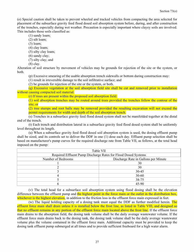
Section 73(o)
(o) Special caution shall be taken to prevent wheeled and tracked vehicles from compacting the area selected for placement of the subsurface gravity feed flood dosed soil absorption system before, during, and after construction of the trenches, especially during wet weather. Precaution is especially important where clayey soils are involved. This includes those soils classified as:
(1) sandy loam; (2) silt loam; (3) loam; (4) clay loam; (5) silty clay loam; (6) sandy clay; (7) silty clay; and (8) clay.
Alteration of soil structure by movement of vehicles may be grounds for rejection of the site or the system, or both. (p) Excessive smearing of the usable absorption trench sidewalls or bottom during construction may:
(1) result in irreversible damage to the soil infiltrative surface; and (2) be grounds for rejection of the site or the system, or both.
(q) Excessive vegetation at the soil absorption field site shall be cut and removed prior to installation without causing compacted soil material. (r) If trees are present within the proposed soil absorption field:
(1) soil absorption trenches may be routed around trees provided the trenches follow the contour of the site; or (2) tree stumps and root balls may be removed provided the resulting excavation will not exceed the permit requirements for width and depth of the soil absorption trench.
(s) Trenches in a subsurface gravity feed flood dosed system shall not be manifolded together at the distal end of the trench. (t) Each trench and distribution lateral in a subsurface gravity feed flood dosed system shall be uniformly level throughout its length. (u) When a subsurface gravity feed flood dosed soil absorption system is used, the dosing effluent pump shall be sized, and its controls set to deliver the DDF in one (1) dose each day. Effluent pump selection shall be based on manufacturer's pump curves for the required discharge rate from Table VII, as follows, at the total head imposed on the pump:
Table VII Required Effluent Pump Discharge Rates for Flood Dosed Systems
Number of Bedrooms Discharge Rate in Gallons per Minute 1 30 2 30 3 30-45 4 30-60 5 38-75 6 45-90
(v) The total head for a subsurface soil absorption system using flood dosing shall be the elevation difference between the effluent pump and the highest point in the force main or the outlet in the distribution box, whichever is the highest elevation, in addition to the friction loss in the effluent force main expressed in feet. (w) The liquid holding capacity of a dosing tank must equal the DDF as further modified herein. The effluent force main shall drain unless it is installed below the frost line, as listed in Table VIII, and designed so that no effluent remains in any portion of the effluent force main located above the frost line. If the effluent force main drains to the absorption field, the dosing tank volume shall be the daily average wastewater volume. If the effluent force main drains back to the dosing tank, the dosing tank volume shall be the daily average wastewater volume plus the volume contained in the effluent force main. Additional capacity must be provided to keep the dosing tank effluent pump submerged at all times and to provide sufficient freeboard for a high water alarm.
27
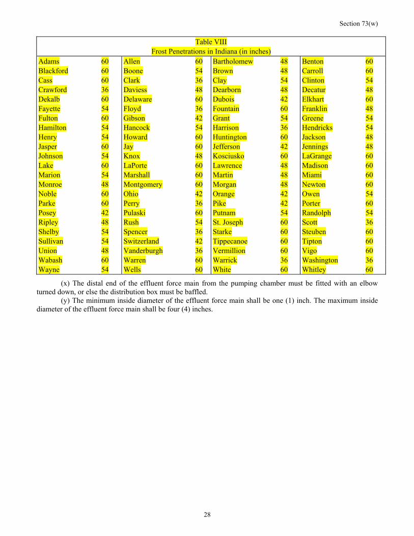
Section 73(w)
Table VIII Frost Penetrations in Indiana (in inches)
Adams 60 Allen 60 Bartholomew 48 Benton 60 Blackford 60 Boone 54 Brown 48 Carroll 60 Cass 60 Clark 36 Clay 54 Clinton 54 Crawford 36 Daviess 48 Dearborn 48 Decatur 48 Dekalb 60 Delaware 60 Dubois 42 Elkhart 60 Fayette 54 Floyd 36 Fountain 60 Franklin 48 Fulton 60 Gibson 42 Grant 54 Greene 54 Hamilton 54 Hancock 54 Harrison 36 Hendricks 54 Henry 54 Howard 60 Huntington 60 Jackson 48 Jasper 60 Jay 60 Jefferson 42 Jennings 48 Johnson 54 Knox 48 Kosciusko 60 LaGrange 60 Lake 60 LaPorte 60 Lawrence 48 Madison 60 Marion 54 Marshall 60 Martin 48 Miami 60 Monroe 48 Montgomery 60 Morgan 48 Newton 60 Noble 60 Ohio 42 Orange 42 Owen 54 Parke 60 Perry 36 Pike 42 Porter 60 Posey 42 Pulaski 60 Putnam 54 Randolph 54 Ripley 48 Rush 54 St. Joseph 60 Scott 36 Shelby 54 Spencer 36 Starke 60 Steuben 60 Sullivan 54 Switzerland 42 Tippecanoe 60 Tipton 60 Union 48 Vanderburgh 36 Vermillion 60 Vigo 60 Wabash 60 Warren 60 Warrick 36 Washington 36 Wayne 54 Wells 60 White 60 Whitley 60
(x) The distal end of the effluent force main from the pumping chamber must be fitted with an elbow turned down, or else the distribution box must be baffled. (y) The minimum inside diameter of the effluent force main shall be one (1) inch. The maximum inside diameter of the effluent force main shall be four (4) inches.
28
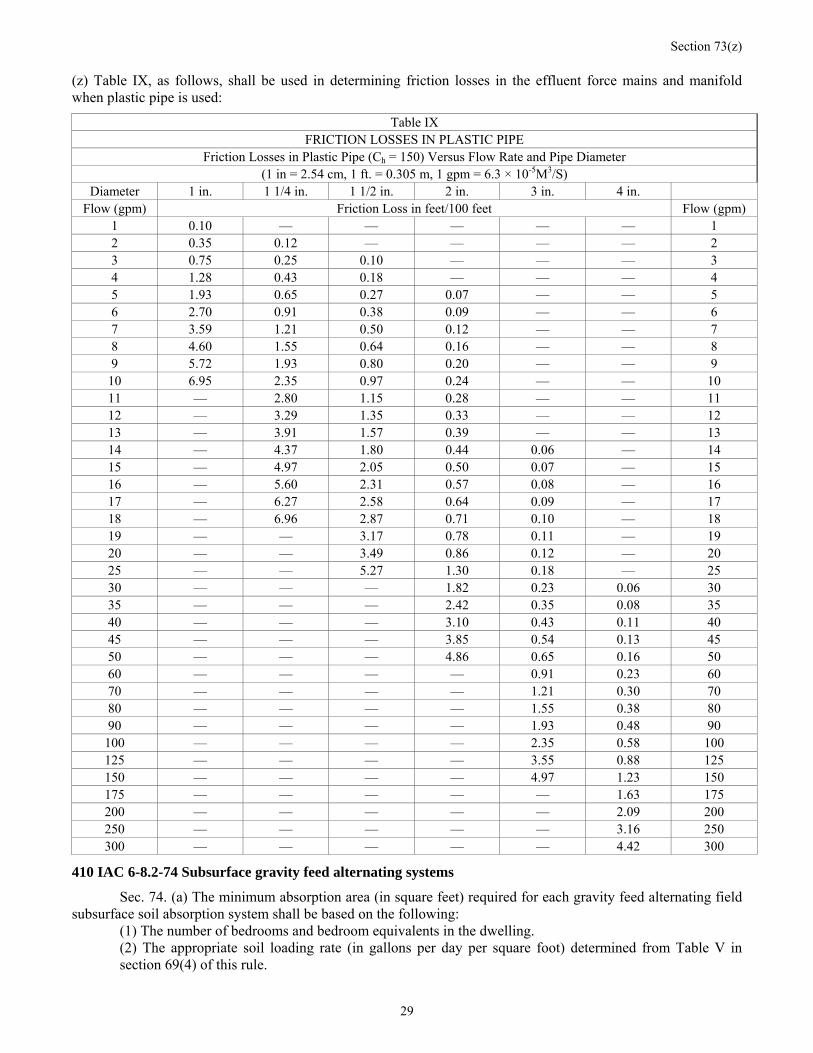
Section 73(z)
(z) Table IX, as follows, shall be used in determining friction losses in the effluent force mains and manifold when plastic pipe is used:
Table IX FRICTION LOSSES IN PLASTIC PIPE
Friction Losses in Plastic Pipe (Ch = 150) Versus Flow Rate and Pipe Diameter (1 in = 2.54 cm, 1 ft. = 0.305 m, 1 gpm = 6.3 × 10⁻⁵M3/S)
Diameter 1 in. 1 1/4 in. 1 1/2 in. 2 in. 3 in. 4 in. Flow (gpm) Friction Loss in feet/100 feet Flow (gpm)
1 0.10 — — — — — 1 2 0.35 0.12 — — — — 2 3 0.75 0.25 0.10 — — — 3 4 1.28 0.43 0.18 — — — 4 5 1.93 0.65 0.27 0.07 — — 5 6 2.70 0.91 0.38 0.09 — — 6 7 3.59 1.21 0.50 0.12 — — 7 8 4.60 1.55 0.64 0.16 — — 8 9 5.72 1.93 0.80 0.20 — — 9
10 6.95 2.35 0.97 0.24 — — 10 11 — 2.80 1.15 0.28 — — 11 12 — 3.29 1.35 0.33 — — 12 13 — 3.91 1.57 0.39 — — 13 14 — 4.37 1.80 0.44 0.06 — 14 15 — 4.97 2.05 0.50 0.07 — 15 16 — 5.60 2.31 0.57 0.08 — 16 17 — 6.27 2.58 0.64 0.09 — 17 18 — 6.96 2.87 0.71 0.10 — 18 19 — — 3.17 0.78 0.11 — 19 20 — — 3.49 0.86 0.12 — 20 25 — — 5.27 1.30 0.18 — 25 30 — — — 1.82 0.23 0.06 30 35 — — — 2.42 0.35 0.08 35 40 — — — 3.10 0.43 0.11 40 45 — — — 3.85 0.54 0.13 45 50 — — — 4.86 0.65 0.16 50 60 — — — — 0.91 0.23 60 70 — — — — 1.21 0.30 70 80 — — — — 1.55 0.38 80 90 — — — — 1.93 0.48 90
100 — — — — 2.35 0.58 100 125 — — — — 3.55 0.88 125 150 — — — — 4.97 1.23 150 175 — — — — — 1.63 175 200 — — — — — 2.09 200 250 — — — — — 3.16 250 300 — — — — — 4.42 300
410 IAC 6-8.2-74 Subsurface gravity feed alternating systems
Sec. 74. (a) The minimum absorption area (in square feet) required for each gravity feed alternating field subsurface soil absorption system shall be based on the following:
(1) The number of bedrooms and bedroom equivalents in the dwelling. (2) The appropriate soil loading rate (in gallons per day per square foot) determined from Table V in section 69(4) of this rule.
29
Section 74(a)(3)
(3) The vertical separation distance between the bottom of the proposed trench and any soil layer with a soil loading rate of less than twenty-five hundredths (0.25) gallons per day per square foot. The soil loading rate used for this computation shall be the soil loading rate of the most restrictive horizon in the first twenty-four (24) inches below the trench bottom. (4) The absorption area shall be computed using the following formula:
Area = 150 g × number of bedrooms and bedroom equivalents Soil loading rate in gpd/sq. ft.
[The SAF reduction on depth of suitable soil has been removed.] (b) All subsurface gravity feed alternating field systems shall be located in accordance with the separation
distances shown in Table II in section 56(a) of this rule. Subsurface gravity feed alternating systems shall not be constructed where there exist horizons, layers, or strata within thirty-four (34) inches of the ground surface with a soil loading rate less than twenty-five hundredths (0.25) gallons per day per square foot or greater than seventy-five hundredths (0.75) gallons per day per square foot as determined from Table V in section 69(4) of this rule. (c) Subsurface gravity feed alternating field systems shall not be wholly or partly located in a drainage way subject to intermittent flooding. (d) A diversion valve shall be installed between the septic tank and the distribution boxes. An access riser, extending to the ground surface, shall be installed over the diversion valve. (e) Each trench and distribution lateral in a subsurface gravity feed alternating system shall be uniformly level throughout its length. (f) In order to provide equal flow distribution in gravity feed alternating field subsurface soil absorption systems, the absorption trenches in each side of the system must be individually connected to a distribution box by at least five (5) feet of unperforated pipe that is laid with a gravel free backfill. All absorption trenches served by a common distribution box must be constructed so that each square foot of the absorptive area served by the distribution box is loaded with an equal volume of effluent. The distal ends of the distribution laterals may be manifolded together by piping on sites with slopes of two percent (2%) or less, but shall not be tied together on sites with slopes of greater than two percent (2%). When the distal ends of the absorption trenches are manifolded, the manifold trench area shall not count as meeting any of the minimum absorption area required by subsection (a). (g) All absorption field distribution laterals shall have an internal diameter of four (4) inches. (h) No single absorption trench shall exceed one hundred (100) feet in length. (i) On sloping sites, absorption trenches shall be constructed along the contour. (j) There shall be a minimum separation of seven and one-half (7 1/2) feet, on center, between absorption field trenches, measured perpendicular to the trenches. (k) All subsurface gravity feed alternating systems shall be designed to utilize trenches with a minimum width of eighteen (18) inches and a maximum trench width of thirty-six (36) inches. (l) The minimum depth from original grade to the bottom of a subsurface gravity feed alternating field absorption trench shall not be less than ten (10) inches, and the maximum depth to the bottom of the trench shall not be more than thirty-six (36) inches. (m) Perforated pipe distribution laterals in the subsurface gravity feed alternating field soil absorption trench shall be completely surrounded by aggregate that meets the specifications in section 67 of this rule. There shall be at least six (6) inches of aggregate below the pipe. (n) The minimum depth of aggregate above the distribution laterals shall be as follows:
(1) Two (2) inches throughout the entire length and width of trenches having a depth of twelve (12) inches or greater. (2) Two (2) inches above the distribution lateral for the entire length of trenches having a depth of ten (10) to twelve (12) inches.
(o) The aggregate shall be covered with a geotextile fabric barrier that meets the minimum requirements in section 66 of this rule. The barrier shall be installed in such a manner as to prevent the aggregate from becoming clogged with the earth fill. [The use of straw has been removed.] (p) A minimum of twelve (12) inches of cover shall be provided over the aggregate in the trenches, and any fill required to provide cover shall be crowned over the entire field to promote surface runoff.
30
Section 74(q)
(q) Subsurface gravity feed alternating field soil absorption systems shall not be constructed in clayey soils during periods of wet weather when the soil is sufficiently wet at the depth of installation to exceed its plastic limit. This includes those soils classified as:
(1) sandy loam; (2) silt loam; (3) loam; (4) clay loam; (5) silty clay loam; (6) sandy clay; (7) silty clay; and (8) clay.
For the purpose of this rule, the plastic limit of a soil shall be considered to have been exceeded when the soil can be rolled between the palms of the hands to produce threads one-eighth (1/8) inch in diameter without breaking apart and crumbling. (r) Special caution shall be taken to prevent wheeled and tracked vehicles from compacting the area selected for placement of the subsurface gravity feed alternating field soil absorption system before, during, and after construction of the trenches, especially during wet weather. Precaution is especially important where clayey soils are involved. This includes those soils classified as:
(1) sandy loam; (2) silt loam; (3) loam; (4) clay loam; (5) silty clay loam; (6) sandy clay; (7) silty clay; and (8) clay.
Alteration of soil structure by movement of vehicles may be grounds for rejection of the site or the system, or both. (s) Excessive smearing of the usable absorption trench sidewalls or bottom during construction may:
(1) result in irreversible damage to the soil infiltrative surface; and (2) be grounds for rejection of the site or the system, or both.
(t) Excessive vegetation at the soil absorption field site shall be cut and removed prior to installation without causing compacted soil material. (u) If trees are present within the proposed soil absorption field:
(1) soil absorption trenches may be routed around trees provided the trenches follow the contour of the site; or (2) tree stumps and root balls may be removed provided the resulting excavation will not exceed the permit requirements for width and depth of the soil absorption trench.
410 IAC 6-8.2-75 Subsurface pressure distribution systems
Sec. 75. (a) The minimum absorption area (in square feet) required for each subsurface pressure distribution soil absorption system shall be based on the following:
(1) The number of bedrooms and bedroom equivalents in the dwelling. (2) The appropriate soil loading rate (in gallons per day per square foot) determined from Table V in section 69(4) of this rule. (3) The vertical separation distance between the bottom of the proposed trench and any soil layer with a soil loading rate of less than twenty-five hundredths (0.25) gallons per day per square foot. The soil loading rate used for this computation shall be the soil loading rate of the most restrictive horizon in the first twenty-four (24) inches below the trench bottom.
31

Section 75(a)(4)
(4) The absorption area shall be computed using the following formula:
Area = 150 g × number of bedrooms and bedroom equivalents Soil loading rate in gpd/sq. ft.
[The SAF reduction on depth of suitable soil has been removed.] (b) All subsurface pressure distribution systems shall be located in accordance with the separation
distances shown in Table II in section 56(a) of this rule. Subsurface pressure distribution systems shall not be constructed where there exist horizons, layers, or strata within thirty-four (34) inches of the ground surface with a soil loading rate greater than one and twenty-hundredths (1.20) gallons per day per square foot as determined from Table V in section 69(4) of this rule unless that hazard can be overcome through system design. (c) Subsurface pressure distribution soil absorption systems shall not be wholly or partly located in a drainage way subject to intermittent flooding. (d) On sloping sites, absorption trenches in subsurface pressure distribution systems shall be constructed along the contour. (e) There shall be a minimum separation of seven and one-half (7 1/2) feet, on center, between absorption field trenches in subsurface pressure distribution systems, measured perpendicular to the trenches. (f) All subsurface pressure distribution systems shall be designed to utilize trenches with a minimum width of eighteen (18) inches and a maximum trench width of thirty-six (36) inches. (g) The minimum depth from original grade to the bottom of a trench in a subsurface pressure distribution system shall not be less than ten (10) inches, and the maximum depth to the bottom of a trench in a subsurface pressure distribution system shall not be more than thirty-six (36) inches. (h) Perforated pipe distribution laterals in the absorption trench of a subsurface pressure distribution system shall be completely surrounded by aggregate that meets the specifications in section 67 of this rule. There shall be at least six (6) inches of aggregate below the pipe. (i) The minimum depth of aggregate above the distribution laterals shall be as follows:
(1) Two (2) inches throughout the entire length and width of trenches having a depth of twelve (12) inches or greater. (2) Two (2) inches above the distribution lateral for the entire length of trenches having a depth of ten (10) to twelve (12) inches.
(j) The aggregate in a subsurface pressure distribution system shall be covered with a geotextile fabric barrier that meets the minimum requirements in section 66 of this rule, in such a manner as to prevent the aggregate from becoming clogged with the earth fill. [The use of straw has been removed.] (k) A minimum of twelve (12) inches of cover shall be provided over the aggregate in the trenches, and any fill required to provide cover shall be crowned over the entire field to promote surface runoff. (l) Subsurface pressure distribution systems shall not be constructed in clayey soils during periods of wet weather when the soil is sufficiently wet at the depth of installation to exceed its plastic limit. This includes those soils classified as:
(1) sandy loam; (2) silt loam; (3) loam; (4) clay loam; (5) silty clay loam; (6) sandy clay; (7) silty clay; and (8) clay.
For the purpose of this rule, the plastic limit of a soil shall be considered to have been exceeded when the soil can be rolled between the palms of the hands to produce threads one-eighth (1/8) inch in diameter without breaking apart and crumbling.
32

Section 75(m)
(m) Special caution shall be taken to prevent wheeled and tracked vehicles from compacting the area selected for placement of the subsurface pressure distribution system before, during, and after construction of the trenches, especially during wet weather. Precaution is especially important where clayey soils are involved. This includes those soils classified as:
(1) sandy loam; (2) silt loam; (3) loam; (4) clay loam; (5) silty clay loam; (6) sandy clay; (7) silty clay; and (8) clay.
Alteration of soil structure by movement of vehicles may be grounds for rejection of the site or the system, or both. (n) Excessive smearing of the usable absorption trench sidewalls or bottom during construction may:
(1) result in irreversible damage to the soil infiltrative surface; and (2) be grounds for rejection of the site or the system, or both.
(o) Excessive vegetation at the soil absorption field site shall be cut and removed prior to installation without causing compacted soil material. (p) If trees are present within the proposed soil absorption field:
(1) soil absorption trenches may be routed around trees provided the trenches follow the contour of the site; or (2) tree stumps and root balls may be removed provided the resulting excavation will not exceed the permit requirements for width and depth of the soil absorption trench.
(q) Each pipe connected to an outlet in the manifold of a subsurface pressure distribution system shall be counted as a separate distribution lateral. (r) Trenches in a subsurface pressure distribution system shall not be manifolded together at the distal end of the trench. (s) Each trench and distribution lateral in a subsurface pressure distribution system shall be uniformly level throughout its length. (t) The effluent pump shall be sized, and its controls set as follows:
(1) When a subsurface pressure distribution system is designed using a soil loading rate of less than one and two-tenths (1.2) gallons per day per square foot, the pump shall deliver the DDF in one (1) dose each day while maintaining an inline residual pressure of two and five-tenths (2.5) to three (3) feet of head in the distribution lateral at the highest elevation in the soil absorption system during pumping. (2) When a subsurface pressure distribution system is designed using a soil loading rate of one and two-tenths (1.2) gallons per day per square foot, the pump shall deliver four (4) doses each day, each dose being approximately one-fourth (1/4) of the DDF, while maintaining an inline residual pressure of two and five-tenths (2.5) to three (3) feet of head in the distribution lateral at the highest elevation in the soil absorption system during pumping.
(u) The effluent force main shall drain unless it is installed below the frost line, as listed in Table VIII in section 73 of this rule and designed so that no effluent remains in any portion of the effluent force main located above the frost line. If the effluent force main drains to the subsurface pressure distribution system, the dosing tank volume shall be the dose calculated using subsection (t)(1) or (t)(2), whichever is applicable. If the effluent force main drains back to the dosing tank, the dosing tank volume shall be the dose calculated using subsection (t)(1) or (t)(2), whichever is applicable, plus the volume contained in the effluent force main. Additional dosing tank capacity must be provided to:
(1) keep the dosing tank effluent pump submerged at all times; and (2) provide sufficient freeboard for a high water alarm.
(v) The minimum inside diameter of the effluent force main shall be one and one-half (1 1/2) inches [previous rule was 2 inches]. The maximum inside diameter of the effluent force main shall be four (4) inches. (w) Table IX in section 73(z) of this rule shall be used in determining friction losses in the effluent force mains and manifold when plastic pipe is used.
33
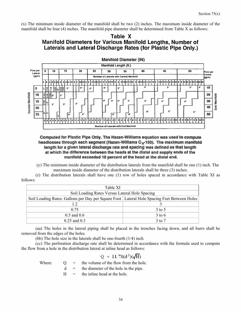
Section 75(x)
(x) The minimum inside diameter of the manifold shall be two (2) inches. The maximum inside diameter of the manifold shall be four (4) inches. The manifold pipe diameter shall be determined from Table X as follows:
(y) The minimum inside diameter of the distribution laterals from the manifold shall be one (1) inch. The maximum inside diameter of the distribution laterals shall be three (3) inches.
(z) The distribution laterals shall have one (1) row of holes spaced in accordance with Table XI as follows:
Table XI Soil Loading Rates Versus Lateral Hole Spacing
Soil Loading Rates: Gallons per Day per Square Foot Lateral Hole Spacing Feet Between Holes1.2 3
0.75 3 to 5 0.5 and 0.6 3 to 6
0.25 and 0.3 3 to 7
(aa) The holes in the lateral piping shall be placed in the trenches facing down, and all burrs shall be removed from the edges of the holes. (bb) The hole size in the laterals shall be one-fourth (1/4) inch. (cc) The perforation discharge rate shall be determined in accordance with the formula used to compute the flow from a hole in the distribution lateral at inline head as follows:
Where: Q = the volume of the flow from the hole.
d = the diameter of the hole in the pipe. H = the inline head at the hole.
34
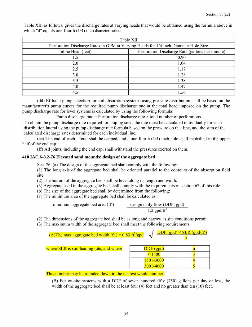
Section 75(cc)
Table XII, as follows, gives the discharge rates at varying heads that would be obtained using the formula above in which "d" equals one-fourth (1/4) inch diameter holes:
Table XII Perforation Discharge Rates in GPM at Varying Heads for 1/4 Inch Diameter Hole Size
Inline Head (feet) Perforation Discharge Rate (gallons per minute) 1.5 0.90 2.0 1.04 2.5 1.17 3.0 1.28 3.5 1.38 4.0 1.47 4.5 1.56
(dd) Effluent pump selection for soil absorption systems using pressure distribution shall be based on the manufacturer's pump curves for the required pump discharge rate at the total head imposed on the pump. The pump discharge rate for level systems is calculated by using the following formula:
Pump discharge rate = Perforation discharge rate × total number of perforations To obtain the pump discharge rate required for sloping sites, the rate must be calculated individually for each distribution lateral using the pump discharge rate formula based on the pressure on that line, and the sum of the calculated discharge rates determined for each individual line.
(ee) The end of each lateral shall be capped, and a one-fourth (1/4) inch hole shall be drilled in the upper half of the end cap. (ff) All joints, including the end cap, shall withstand the pressures exerted on them.
410 IAC 6-8.2-76 Elevated sand mounds: design of the aggregate bed
Sec. 76. (a) The design of the aggregate bed shall comply with the following: (1) The long axis of the aggregate bed shall be oriented parallel to the contours of the absorption field site. (2) The bottom of the aggregate bed shall be level along its length and width. (3) Aggregate used in the aggregate bed shall comply with the requirements of section 67 of this rule.
(b) The size of the aggregate bed shall be determined from the following: (1) The minimum area of the aggregate bed shall be calculated as:
minimum aggregate bed area (ft2) = design daily flow (DDF, gpd) 1.2 gpd/ft2
(2) The dimensions of the aggregate bed shall be as long and narrow as site conditions permit. (3) The maximum width of the aggregate bed shall meet the following requirements:
35
where SLR is soil loading rate, and where DDF (gpd) n ≤ 1500 3 1501-3000 4 3001-4000 5
This number may be rounded down to the nearest whole number. (B) For on-site systems with a DDF of seven hundred fifty (750) gallons per day or less, the width of the aggregate bed shall be at least four (4) feet and no greater than ten (10) feet.
(A)The max aggregate bed width (ft.) = 0.83 ft2/gpd DDF (gpd) × SLR (gpd/ft2) n
Section 76(b)(3)(C)
(C) For on-site systems with a DDF of greater than seven hundred fifty (750) gallons per day, the following:
(i) If the soil loading rate is fifty-hundredths (0.50) gallons per day per square foot (gpd/ft2) or less, the width of the aggregate bed shall be no greater than fifteen (15) feet. (ii) If the soil loading rate is greater than fifty-hundredths (0.50) gallons per day per square foot (gpd/ft2), the width of the aggregate bed shall be no greater than twenty (20) feet.
(4) The minimum length of the aggregate bed shall be calculated as: min. length (L) = min. aggregate bed area/max. aggregate bed width (AB)
(5) If more than one (1) aggregate bed is constructed, each of the aggregate beds shall be equal in area. (6) The depth of the aggregate bed shall be at least the sum of:
(A) six (6) inches of aggregate below the pressure distribution lateral; (B) the outside diameter of the pressure distribution lateral; and (C) at least two (2) inches of aggregate above the pressure distribution lateral.
(7) The aggregate bed shall be installed in INDOT Specification 23 sand in the basal area, as listed in Table XIII, as follows:
Table XIII INDOT Specification 23 Sand
Sieve Sizes Percent (%) Passing Sieve (by Weight) 3/8 in (9.50 mm) 100 No. 4 (4.75 mm) 95 – 100 No. 8 (2.36 mm) 80 – 100
No. 16 (1.18 mm) 50 – 85 No. 30 (600 μm) 25 – 60 No. 50 (300 μm) 5 – 30
No. 100 (150 μm) 0 – 10 No. 200 (75 μm) 0 – 3
*The sand shall not have more than forty-five percent (45%) retained between any two (2) consecutive sieves.
(8) A one (1) foot wide border of INDOT Specification 23 sand, level with the top of the aggregate bed, shall surround the aggregate bed.
(c) The location of the aggregate bed shall be: (1) for sites with slopes of one-half percent (1/2%) or less, in the center of the basal area; and (2) for sites with slopes greater than one-half percent (1/2%) and less than or equal to six percent (6%), at the upslope side of the basal area. [The previous rule did not define level vs. sloping]
Figure 1, Plan View of Elevated Sand Mound (Based on Minimum Dimensions), presents a visual depiction of the location of the aggregate bed within the basal area.
36
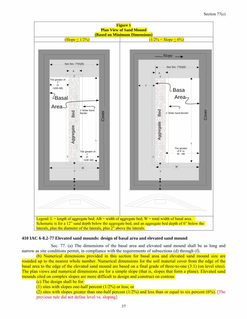
Section 77(c)
Figure 1 Plan View of Sand Mound
(Based on Minimum Dimensions) (Slope < 1/2%) (1/2% < Slope < 6%)
Legend: L = length of aggregate bed; AB = width of aggregate bed; W = total width of basal area. Schematic is for a 12” sand depth below the aggregate bed, and an aggregate bed depth of 6” below the laterals, plus the diameter of the laterals, plus 2” above the laterals.
37
410 IAC 6-8.2-77 Elevated sand mounds: design of basal area and elevated sand mound
Sec. 77. (a) The dimensions of the basal area and elevated sand mound shall be as long and narrow as site conditions permit, in compliance with the requirements of subsections (d) through (f). (b) Numerical dimensions provided in this section for basal area and elevated sand mound size are rounded up to the nearest whole number. Numerical dimensions for the soil material cover from the edge of the basal area to the edge of the elevated sand mound are based on a final grade of three-to-one (3:1) (on level sites). The plan views and numerical dimensions are for a simple slope (that is, slopes that form a plane). Elevated sand mounds sited on complex slopes are more difficult to design and construct on contour. (c) The design shall be for:
(1) sites with slopes one-half percent (1/2%) or less; or (2) sites with slopes greater than one-half percent (1/2%) and less than or equal to six percent (6%). [The previous rule did not define level vs. sloping]
7’ (For a sand depth of 12”) 7’ (For a sand depth of 12”)
3’ 3’
Cov
er
Aggr
egat
e
Bed
BasaArea
A
7’
1’
1’
The greater of 9’ or W - AB
L
7’
1’ Wide Sand Border
3’
Slope
See Sec. 77(h)(5)
W
See Sec. 77(h)(5)
A
Cov
er
1’Ag
greg
ate
Bed
or The greater of
7’
½(W-AB)
1’ or The greater of
7’
½(W AB)
7’
BasalArea
1’ Wide Sand Border
L
W
3’
Section 77(d)
(d) The basal area and elevated sand mound shall be constructed on the tilled surface of the absorption field site in accordance with the provisions of section 82 of this rule. The long axis of the basal area and elevated sand mound shall be oriented parallel to the contour of the absorption field site. (e) The minimum depth of the INDOT Specification 23 sand under the aggregate bed shall be twelve (12) inches. (f) The INDOT Specification 23 sand shall have a minimum final grade on all sides of three-to-one (3:1). (g) The soil material cover shall have a minimum final grade on all sides of three-to-one (3:1). (h) The size and location of the basal area shall be determined from the following:
(1) The minimum size of the basal area shall be calculated as:
minimum basal area (ft2) = design daily flow = DDF (gpd) soil loading rate SLR (gpd/ft2)
using the soil loading rates from Table VI in section 71(4) of this rule. The soil loading rate used for this computation shall be the soil loading rate of the most restrictive horizon in the first twenty (20) inches below the ground surface. (2) The length (L) of the basal area shall equal the length of the aggregate bed. (3) The location of the basal area within the elevated sand mound shall be:
(A) on sites with slopes of one-half percent (1/2%) or less, the area under the aggregate bed and extending an equal distance from each side along the length of the aggregate bed; and
(B) on sites with slopes greater than one-half percent (1/2%) and less than or equal to six percent (6%), the area under the aggregate bed and extending downslope from the aggregate bed. [The previous rule did not define level vs. sloping] Figure 1, Plan View of Elevated Sand Mound (Based on Minimum Dimensions), presents a visual depiction of the location of the basal area within the elevated sand mound. (4) For the calculation of the total width of the basal area (W), the following terms are used:
L = length of aggregate bed AB = width of aggregate bed W = width of basal area 1/2(W-AB) = width of basal area on either side of aggregate bed (on sites with slopes ≤ 1/2%) (W-AB) = width of basal area downslope of aggregate bed (on sites with slopes > ½%)
(5) The minimum width of the basal area shall be calculated as the greater of: (A) Width = minimum basal area (ft.²)
length of aggregate bed (ft) ; or (B) Slope Min. Basal Area Width 0% ≤ slope ≤ 1/2% Agg Bed width + 14 ft. 1/2% < slope ≤ 6% Agg Bed width + 9 ft.
The dimension from (i) or (ii) shall maintain a minimum sideslope grade of three-to-one (3:1), representing the INDOT Specification 23 sand on the downslope side of the aggregate bed. (i) The minimum length of an elevated sand mound shall be the sum of the following:
(1) The length of the aggregate bed (L). (2) Plus fourteen (14) feet, representing the two sideslopes of INDOT Specification 23 sand at both ends of the aggregate bed (including the one (1) foot level borders), and shall maintain a minimum sideslope grade of three-to-one (3:1). (3) Plus six (6) feet, representing the soil material cover at both ends of the aggregate bed.
38
Section 77(j)
(j) The width of the elevated sand mound shall be determined from the following: (1) On sites with slopes one-half percent (1/2%) or less, the minimum width of an elevated sand mound is the sum of the following:
(A) The width of the aggregate bed (AB). (B) Plus the greater of either:
(i) the total width of basal area minus the width of aggregate bed; or (ii) fourteen (14) feet.
The dimension from (i) or (ii) shall maintain a minimum sideslope grade of three-to-one (3:1). (C) Plus six (6) feet, representing the soil material cover on both sides of the aggregate bed.
(2) On sites with slopes greater than one-half percent (1/2%) and less than or equal to six percent (6%), the minimum width of an elevated sand mound shall be the sum of the following:
(A) The width of the aggregate bed (AB). (B) Plus seven (7) feet, representing the sideslope of INDOT Specification 23 sand on the upslope side of the aggregate bed (including the one (1) foot level border), and shall maintain a minimum sideslope grade of three-to-one (3:1). (C) Plus the greater of either:
(i) the total width of basal area minus the width of aggregate bed; or (ii) nine (9) feet.
The dimension from (i) or (ii) shall maintain a minimum sideslope grade of three-to-one (3:1). (D) Plus six (6) feet, representing the soil material cover on both sides of the aggregate bed.
410 IAC 6-8.2-78 Elevated sand mounds: pressure distribution network
Sec. 78. The design of the pressure distribution network shall comply with the requirements of section 75(u) through 75(ff) of this rule and the following:
(1) The effluent force main shall approach the elevated sand mound as follows: (A) On sites with slopes of one-half percent (1/2%) or less, from either end. (B) On sites with slopes greater than one-half percent (1/2%) and less than or equal to six percent (6%), from the upslope side. [The previous rule did not define level vs. sloping]
(2) The dose volume shall be calculated as follows: (A) If the effluent force main and manifold do not drain to the dose tank, the controls for the effluent pump shall be set to deliver one-fourth (1/4) of the DDF (Dose = 1/4 DDF). (B) If the effluent force main and manifold drain to the dose tank, the controls for the effluent pump shall be set to deliver one-fourth (1/4) of the DDF plus the volume of the effluent force main (Dose = 1/4 DDF + VolFM).
(3) A manifold shall comply with the requirements of section 75(w) and 75(x) of this rule and be installed between the effluent force main and the pressure distribution laterals as follows:
(A) The manifold shall be located in the aggregate bed. (B) Each pressure distribution lateral shall connect directly to the manifold. (C) The manifold pipe shall:
(i) for on-site systems with a DDF of seven hundred fifty (750) gallons per day or less, have a diameter of two (2) inches; and (ii) for on-site systems with a DDF of greater than seven hundred fifty (750) gallons per day, have the same diameter as the effluent force main or a diameter of two (2) inches, whichever is greater.
(4) The pressure distribution laterals shall comply with the requirements of section 75(y) through 75(ff) and meet the following requirements:
(A) The design head shall be three (3) feet. [Previous rule was 2.5 to 3] (B) The total discharge rate of the effluent pump shall be the total number of one-quarter (1/4) inch holes in all laterals times one and twenty-eight hundredths (1.28) gallons per minute (gpm).
39
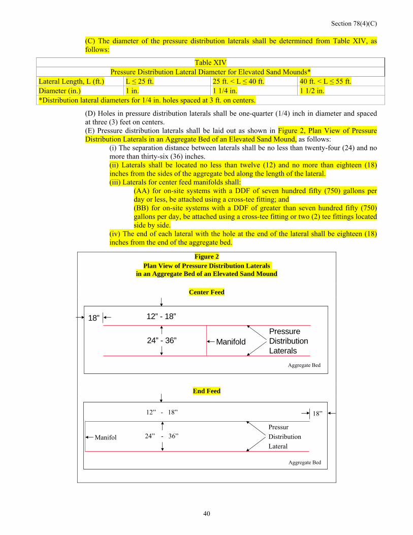
Section 78(4)(C)
(C) The diameter of the pressure distribution laterals shall be determined from Table XIV, as follows:
Table XIV Pressure Distribution Lateral Diameter for Elevated Sand Mounds*
Lateral Length, L (ft.) L ≤ 25 ft. 25 ft. < L ≤ 40 ft. 40 ft. < L ≤ 55 ft. Diameter (in.) 1 in. 1 1/4 in. 1 1/2 in. *Distribution lateral diameters for 1/4 in. holes spaced at 3 ft. on centers.
(D) Holes in pressure distribution laterals shall be one-quarter (1/4) inch in diameter and spaced at three (3) feet on centers. (E) Pressure distribution laterals shall be laid out as shown in Figure 2, Plan View of Pressure Distribution Laterals in an Aggregate Bed of an Elevated Sand Mound, as follows:
(i) The separation distance between laterals shall be no less than twenty-four (24) and no more than thirty-six (36) inches. (ii) Laterals shall be located no less than twelve (12) and no more than eighteen (18) inches from the sides of the aggregate bed along the length of the lateral. (iii) Laterals for center feed manifolds shall:
(AA) for on-site systems with a DDF of seven hundred fifty (750) gallons per day or less, be attached using a cross-tee fitting; and (BB) for on-site systems with a DDF of greater than seven hundred fifty (750) gallons per day, be attached using a cross-tee fitting or two (2) tee fittings located side by side.
(iv) The end of each lateral with the hole at the end of the lateral shall be eighteen (18) inches from the end of the aggregate bed.
Figure 2 Plan View of Pressure Distribution Laterals
in an Aggregate Bed of an Elevated Sand Mound Center Feed
End Feed
40
24” - 36”
12” - 18”
ManifolPressur Distribution Lateral
Aggregate Bed
18”
12” - 18”18”Pressure Distribution Laterals
24” - 36”
Aggregate Bed
Manifold
Section 79
410 IAC 6-8.2-79 Elevated sand mounds: protection of the site
Sec. 79. Before the start of any construction on the property, the location of the elevated sand mound: (1) soil absorption field; (2) dispersal area; (3) interceptor drain; (4) perimeter drain; (5) segment drain; (6) set-aside area (if required in the approved plan); and (7) areas designated for future expansion (if required in the approved plan);
shall be staked out and protected from disturbance.
410 IAC 6-8.2-80 Elevated sand mounds: requirements prior to system construction
Sec. 80. (a) Site preparation, tilling, construction, finish grading, and soil stabilization shall: (1) be performed in accordance with the approved plans; (2) not be performed when the soil is frozen; and (3) not be performed when the soil is sufficiently wet to exceed its plastic limit.
(A) Sufficient samples shall be evaluated throughout the soil absorption field site, from the soil surface to the depth of tilling, to assure that the plastic limit of the soil is not exceeded. (B) The plastic limit of a soil is exceeded when the soil can be rolled between the palms of the hands to produce threads one-eighth (1/8) inch in diameter that do not easily break apart or crumble.
410 IAC 6-8.2-81 Elevated sand mounds: installation of the effluent force main
Sec. 81. (a) Before tilling the elevated sand mound site, the: (1) effluent force main from the dosing tank to the basal area shall be installed to a depth of at least sixteen (16) inches below existing grade; and (2) end of the effluent force main shall be fitted with a temporary vertical pipe extending at least three (3) feet above grade and capped.
(b) The effluent force main shall drain back to the dosing tank unless it is installed below the frost line, as listed in Table VIII in section 73(w) of this rule, and designed so that no effluent remains in any portion of the effluent force main located above the frost line.
410 IAC 6-8.2-82 Elevated sand mounds: preparation of the elevated sand mound site
Sec. 82. (a) The portion of the elevated sand mound site receiving INDOT Specification 23 sand shall be tilled parallel to the contour of the site to a depth of seven (7) to fourteen (14) inches [previous rule was 7 to 8 inches] with a moldboard or chisel plow, bulldozer with a ripper, or backhoe. The department or local health department may require field supervision of tilling operations. (b) For wooded sites, the following requirements shall be met for site preparation:
(1) Trees shall be cut off at the ground surface and removed, with only stumps left in place. (2) Roots that protrude above the tilled surface shall be cut off without causing compacted soil material. (3) A backhoe shall be used to till the site.
(A) The use of a backhoe shall be approved, in writing, by the department or local health department. (B) Tilling shall be performed parallel to the contour of the site. (C) The backhoe bucket shall be fitted with chisel teeth. (D) The surface of the ground shall be tilled with the backhoe bucket chisel teeth. (E) The backhoe shall remain on untilled soil.
(c) For nonwooded sites, the following requirements shall be met for site preparation: (1) Excessive vegetation shall be cut and removed (not scraped) prior to installation without causing compacted soil material. (2) If a chisel plow or a bulldozer with a ripper is used, tillage shall be across the site parallel to the contour of the site.
41

Section 82(c)(3)
(3) If a moldboard plow is used: (A) it shall have at least two (2) bottoms and make only one (1) pass across the area, parallel to the contour of the site; and (B) on sites with slopes greater than one-half percent (1/2%), the furrows shall be turned upslope.
(4) A backhoe may be used on tight sites only if the requirements of subsection (b)(3) are met. (d) If compacted soil material is identified in the soil treatment zone, tilling of the soil shall be to a depth of at least two (2) inches below the bottom of the compacted soil material. 410 IAC 6-8.2-83 Elevated sand mounds: placement of the sand on the basal area Sec. 83. (a) The basal area shall be covered using sand that meets the requirements listed in Table XIII in section 73(a)(4) of this rule. (b) INDOT Specification 23 sand shall be placed on the tilled area immediately after tilling the site to protect the tilled surfaces from damage by precipitation. (c) The depth of the INDOT Specification 23 sand under the aggregate bed shall be at least twelve (12) inches (sites with slopes greater than one-half percent (1/2%), the depth of INDOT Specification 23 sand beneath the downslope side of the aggregate bed will be greater than twelve (12) inches). [The previous rule did not define level vs. sloping] (d) INDOT Specification 23 sand shall be placed on the tilled surface as follows: (1) On sites with slopes one-half percent (1/2%) or less, from the ends of the elevated sand mound. [The previous rule did not define level vs. sloping]
(2) On sites with slopes greater than one-half percent (1/2%), from the ends or upslope edge. (e) At least six (6) inches of INDOT Specification 23 sand shall be kept between the vehicle tracks and the tilled soil of the site. (f) The depth of INDOT Specification 23 sand around the aggregate bed shall be the sum of:
(1) the depth of the sand under the aggregate bed; and (2) the depth of the aggregate bed.
(g) A one (1) foot wide border of INDOT Specification 23 sand shall surround the aggregate bed, level with the top of the aggregate bed. 410 IAC 6-8.2-84 Elevated sand mounds: construction of the aggregate bed Sec. 84. (a) The surface of the INDOT Specification 23 sand at the sand/aggregate interface shall be smooth and free of ruts and depressions before the placement of the aggregate. (b) The depth of aggregate shall be at least:
(1) six (6) inches below the pressure distribution lateral; and (2) two (2) inches above the pressure distribution lateral.
(c) The aggregate bed shall be covered with a barrier material as required in section 66 of this rule. The barrier material shall cover the aggregate bed from side to side and from end to end. 410 IAC 6-8.2-85 Elevated sand mounds: placement of the soil material and final grade Sec. 85. (a) If the ground surface along the perimeter of the INDOT Specification 23 sand was not tilled during preparation of the elevated sand mound site, the perimeter shall be prepared by tilling in accordance with the requirements of section 82 of this rule. (b) The surface of the INDOT Specification 23 sand shall be prepared by:
(1) maintaining a minimum grade of at least three-to-one (3:1); and (2) preparing the surface of the INDOT Specification 23 sand so that it is smooth and free of ruts and depressions.
(c) The soil material cover shall: (1) have a texture other than sand or loamy sand; (2) be capable of sustaining plant growth; and (3) be placed on the INDOT Specification 23 sand without causing compacted soil material.
(d) The aggregate and sand of the elevated sand mound shall be covered with a minimum of twelve (12) inches of soil material. Six (6) inches of that soil material shall be placed over the center line of the long axis of the aggregate bed and crowned to promote surface runoff away from the elevated sand mound. (e) Soil material shall be placed on the tilled portion of the sand perimeter and graded according to the requirements of section 82 of this rule
42

Section 85(f)
(f) The soil material cover shall have a minimum final grade on all sides of three-to-one (3:1). (g) The elevated sand mound shall be seeded or sodded with grasses adapted to the area. If seeded, the elevated sand mound shall be protected by a cover of straw, burlap, or some other biodegradable material that will protect it against erosion.
410 IAC 6-8.2-86 Abandonment of an on-site system
Sec. 86. (a) When the use of an on-site sewage system is discontinued, the following procedure must be followed for tanks and electrical service:
(1) Electrical power must be disconnected at the source. All controls and panels must be removed. (2) All electrical lines (including buried service lines) that will not be used for other purposes must be removed. (3) A licensed septic tank cleaner must pump all contents from all tanks in the system. (4) The tanks must be removed or the lids crushed into the tanks. (5) The holes or tanks must be backfilled with debris-free sand or other granular material, concrete, or soil material that is compacted to prevent settling. If a sand mound is being abandoned, sand, aggregate and soil cover from the system may be used for filling the tank or tanks. (6) Properly grade and establish vegetative cover.
(b) The components of the absorption field may be left intact, if there are no plans to use the area for other purposes. Vegetative cover must be maintained.
(1) If effluent has surfaced, those areas must be covered with hydrated lime followed by top soil and a vegetative cover. (2) If components of the absorption field are to be removed, the following:
(A) Allow sufficient time after the system is taken out of service and the tanks pumped to make sure the entire absorption field is completely dry. (B) A licensed septic tank cleaner must pump all contents from all distribution boxes in the system. (C) A contractor must remove the distribution network, aggregate and sand (if any) from the site. (D) The contractor must dispose of the materials at a licensed landfill. (E) The site must be properly graded and a vegetative cover established.
410 IAC 6-8.2-87 Matters incorporated by reference
Sec. 87. (a) Bulletin SE 11, "The Sanitary Vault Privy", 1986 Edition, is incorporated by reference as part of this rule. It may be obtained free of charge by request mailed to the department at 2 North Meridian Street, Indianapolis, Indiana 46204. (b) National Sanitation Foundation Standard Number 40, "Individual Aerobic Wastewater Treatment Plants", is incorporated by reference as part of this rule. Two (2) copies of the standard are available for reference in the files of the department. Copies of the standard may be obtained by mailing a request to the National Sanitation Foundation, 789 North Dixboro Road, P.O. Box 130140, Ann Arbor, Michigan 48113-0140, or at: www.techstreet.com/cgi-bin/joint.cgi/nsf (c) National Sanitation Foundation Standard Number 46, "Evaluation of Components and Devices Used in Wastewater Treatment Systems", is incorporated by reference as part of this rule. Two (2) copies of the standard are available for reference in the files of the department. Copies of the standard may be obtained by mailing a request to the National Sanitation Foundation, 789 North Dixboro Road, P.O. Box 130140, Ann Arbor, Michigan 48113-0140, or at: www.techstreet.com/cgi-bin/joint.cgi/nsf (d) ASTM Standards ASTM C 990-09, ASTM C 1644-06, D 1527-99(2005), D 1785-06, D 2241-09, D 2282-99(2005), D 2661-08, D 2665-09, D 2680-01(2009), D 2729-03, D 2751-05, D 3034-08, F 405-05, F 667-06, F 810-07, C 412-05a, C 4-04(2009), and 498-95 ASTM standards may be obtained at: http://www.astm.org/Standard/index.shtml (e) NRCS Standard 606 may be obtained at: http://efotg.nrcs.usda.gov/references/public/AL/tg606.pdf
43
Related Documents