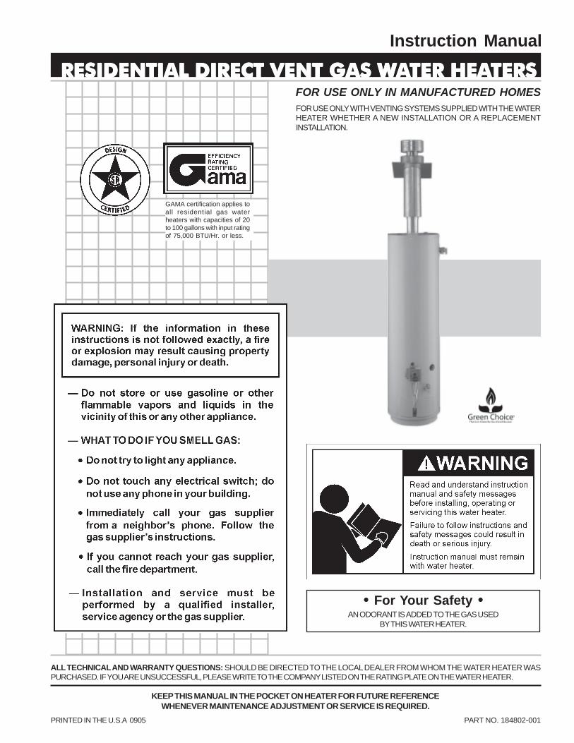
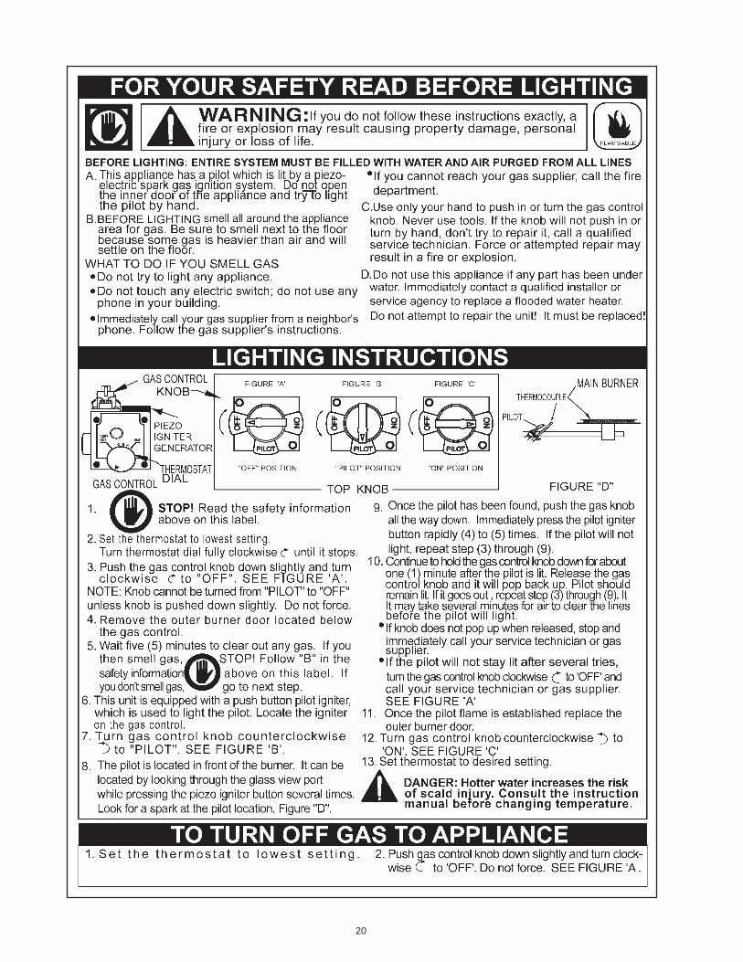
Instruction Manual PRINTED IN THE U.S.A 0905 PART NO. 184802-001 KEEP THIS MANUAL IN THE POCKET ON HEATER FOR FUTURE REFERENCE WHENEVER MAINTENANCE ADJUSTMENT OR SERVICE IS REQUIRED. FOR USE ONLY IN MANUFACTURED HOMES ALL TECHNICAL AND WARRANTY QUESTIONS: SHOULD BE DIRECTED TO THE LOCAL DEALER FROM WHOM THE WATER HEATER WAS PURCHASED. IF YOUARE UNSUCCESSFUL, PLEASE WRITE TO THE COMPANY LISTED ON THE RATING PLATE ON THE WATER HEATER. RESIDENTIAL DIRECT VENT GAS W RESIDENTIAL DIRECT VENT GAS W RESIDENTIAL DIRECT VENT GAS W RESIDENTIAL DIRECT VENT GAS W RESIDENTIAL DIRECT VENT GAS WATER HEA TER HEA TER HEA TER HEA TER HEATERS TERS TERS TERS TERS • For Your Safety • AN ODORANT IS ADDED TO THE GAS USED BY THIS WATER HEATER. GAMA certification applies to all residential gas water heaters with capacities of 20 to 100 gallons with input rating of 75,000 BTU/Hr. or less. FOR USE ONLY WITH VENTING SYSTEMS SUPPLIED WITH THE WATER HEATER WHETHER A NEW INSTALLATION OR A REPLACEMENT INSTALLATION.

Welcome message from author
This document is posted to help you gain knowledge. Please leave a comment to let me know what you think about it! Share it to your friends and learn new things together.
Transcript
1
Instruction Manual
PRINTED IN THE U.S.A 0905 PART NO. 184802-001
KEEP THIS MANUAL IN THE POCKET ON HEATER FOR FUTURE REFERENCEWHENEVER MAINTENANCE ADJUSTMENT OR SERVICE IS REQUIRED.
FOR USE ONLY IN MANUFACTURED HOMES
ALL TECHNICAL AND WARRANTY QUESTIONS: SHOULD BE DIRECTED TO THE LOCAL DEALER FROM WHOM THE WATER HEATER WASPURCHASED. IF YOU ARE UNSUCCESSFUL, PLEASE WRITE TO THE COMPANY LISTED ON THE RATING PLATE ON THE WATER HEATER.
RESIDENTIAL DIRECT VENT GAS WRESIDENTIAL DIRECT VENT GAS WRESIDENTIAL DIRECT VENT GAS WRESIDENTIAL DIRECT VENT GAS WRESIDENTIAL DIRECT VENT GAS WAAAAATER HEATER HEATER HEATER HEATER HEATERSTERSTERSTERSTERS
• For Your Safety •AN ODORANT IS ADDED TO THE GAS USED
BY THIS WATER HEATER.
GAMA certification applies toall residential gas waterheaters with capacities of 20to 100 gallons with input ratingof 75,000 BTU/Hr. or less.
FOR USE ONLY WITH VENTING SYSTEMS SUPPLIED WITH THE WATERHEATER WHETHER A NEW INSTALLATION OR A REPLACEMENTINSTALLATION.
2
SAFE INSTSAFE INSTSAFE INSTSAFE INSTSAFE INSTALLAALLAALLAALLAALLATIONTIONTIONTIONTION, USE AND SERVICE, USE AND SERVICE, USE AND SERVICE, USE AND SERVICE, USE AND SERVICE
Your safety and the safety of others is extremely important in the installation, use and servicing of this water heater.
Many safety-related messages and instructions have been provided in this manual and on your own water heater to warn you andothers of a potential injury hazard. Read and obey all safety messages and instructions throughout this manual. It is veryimportant that the meaning of each safety message is understood by you and others who install, use or service this water heater.
This is the safety alert symbol. It is used to alert youto potential personal injury hazards. Obey all safetymessages that follow this symbol to avoid possibleinjury or death.
All safety messages will generally tell you about the type of hazard, what can happen if you do not follow the safety message andhow to avoid the risk of injury.
IMPORTANT DEFINITIONS
• Qualified Installer: A qualified installer must have ability equivalent to a licensed tradesman in the fields of plumbing,air supply, venting and gas supply, including a thorough understanding of the requirements of the National Fuel GasCode as it relates to the installation of gas fired water heaters. The qualified installer must also be familiar with thedesign features and have a thorough understanding of this instruction manual.
• Service Agency: A service agency also must have ability equivalent to a licensed tradesman in the fields of plumbing,air supply, venting and gas supply, including a thorough understanding of the requirements of the National Fuel GasCode as it relates to the installation of gas fired water heaters. The service agency must also have a thoroughunderstanding of this instruction manual, and be able to perform repairs strictly in accordance with the service guidelinesprovided by the manufacturer.
• Gas Supplier: The Natural Gas or Propane Utility or service who supplies gas for utilization by the gas burningappliances within this application. The gas supplier typically has responsibility for the inspection and code approval ofgas piping up to and including the Natural Gas meter or Propane storage tank of a building. Many gas suppliers alsooffer service and inspection of appliances within the building.
DANGER
WARNING
CAUTION
DANGER indicates an imminentlyhazardous situation which, if not avoided,could result in death or injury.
WARNING indicates a potentially hazardoussituation which, if not avoided, could resultin death or injury.
CAUTION indicates a potentially hazardoussituation which, if not avoided, may resultin minor or moderate injury.
CAUTION used without the safety alertsymbol indicates a potentially hazardoussituation which, if not avoided, could resultin property damage.
CAUTION
3
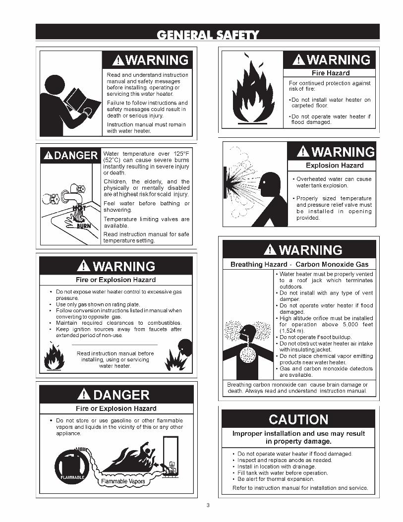
GENERAL SAFETYGENERAL SAFETYGENERAL SAFETYGENERAL SAFETYGENERAL SAFETY
4
SAFE INSTALLATION, USE AND SERVICE ................................ 2GENERAL SAFETY ...................................................................... 3TABLE OF CONTENTS ................................................................. 4INTRODUCTION ............................................................................ 4
Preparing for the New Installation ........................................ 4TYPICAL INSTALLATION .......................................................... 5-6LOCATING THE NEW WATER HEATER ....................................... 7
Facts to Consider About Location ..................................... 7-8Insulation Blankets ............................................................... 8-9
INSTALLING THE NEW WATER HEATER ............................... 9-19Water Heater Installation .................................................. 9-10Securing Water Heater to Floor and Wall .......................... 10Roof Jack Installation ...................................................... 11-14Manufactured Home installed Over Basement orCrawlspace-Air Intake Through an Outside wall ........ 12,13
Cutting Opening Through an Outside Wall andCollar Installation ............................................................. 13Cementing PVC, ABS or CPVC Pipe and Fittings ......... 14
Water Piping .......................................................................... 14T & P Valve and Pipe Insulation ................................ 14,15
Water Piping Pressure Test ................................................. 15Temperature Pressure Relief Valve .............................. 15,16Filling the Water Heater ....................................................... 16Gas Piping ......................................................................... 16,17Sediment Traps ..................................................................... 17Fuel Conversion Instructions from Natural Gasto Propane (L.P.) Gas ..................................................... 17,19
Fuel Conversion Instructions from Propane (L.P.)to Natural Gas ....................................................................... 19
LIGHTING & OPERATING LABEL .............................................. 20TEMPERATURE REGULATION ................................................... 21FOR YOUR INFORMATION ................................................... 21-22
Start Up Conditions ............................................................... 21Condensate ................................................................. 21,22Smoke/Odor ...................................................................... 22Thermal Expansion .......................................................... 22Strange Sounds ............................................................... 22
Operational Conditions ......................................................... 22Smelly Water .................................................................... 22“Air” in Hot Water Faucets ............................................. 22High Temperature Shut Off System .............................. 22
PERIODIC MAINTENANCE .....................................................23-25Venting System Inspection .................................................. 23Burner Inspection ................................................................. 23Burner Cleaning .................................................................... 23Housekeeping ....................................................................... 23Anode Rod Inspection .......................................................... 24Temperature-Pressure Relief Valve Operation ................. 24Draining .................................................................................. 24Drain Valve Washer Replacement ...................................... 24Service ................................................................................... 25
LEAKAGE CHECKPOINTS ......................................................... 25TROUBLESHOOTING ................................................................. 26REPAIR PARTS ........................................................................... 27WARRANTY ........................................................................... Insert
Thank You for purchasing this water heater. Properly installed andmaintained, it should give you years of trouble free service.
Abbreviations Found In This Instruction Manual:
• CSA - Canadian Standards Association• ANSI - American National Standards Institute• NFPA - National Fire Protection Association• ASME - American Society of Mechanical Engineers• GAMA - Gas Appliance Manufacturer’s Association
This gas-fired water heater is design certified by CSA INTERNATIONALunder American National Standard/CSA Standard for Gas Water Heatersfor Manufactured Home Installation, ANSI Z21.10.1 • CSA 4.1(current edition).
PREPARING FOR THE INSTALLATION
1. Read the “General Safety” section, page 3 of this manual first andthen the entire manual carefully. If you don’t follow the safety rules,the water heater will not operate properly. It could cause DEATH,SERIOUS BODILY INJURY AND/OR PROPERTY DAMAGE.
This manual contains instructions for the installation, operation, andmaintenance of the gas-fired water heater. It also contains warningsthroughout the manual that you must read and be aware of. Allwarnings and all instructions are essential to the proper operation ofthe water heater and your safety. Since we cannot put everythingon the first few pages, READ THE ENTIRE MANUAL BEFOREATTEMPTING TO INSTALL OR OPERATE THE WATER HEATER.
2. Instructions to Manufactured Home Manufacturers:The installation must conform with the Manufactured HomeConstruction and Safety Standards Title 24 CFR, Part 3280.
Instruction for replacement installation:
The installation must conform with these instructions and the localcode authority having jurisdiction. In the absence of local codes,installations shall comply with the National Fuel Gas Code ANSIZ223.1/NFPA 54. This publication is available from the CanadianStandards Association, 8501 East Pleasant Valley Rd., ClevelandOhio 44131, or The National Fire Protection Association,1 Batterymarch Park, Quincy, MA 02269.
3. If after reading this manual you have any questions or do notunderstand any portion of the instructions, call the local gas utility orthe manufacturer whose name appears on the rating plate.
4. Carefully plan the place where you are going to put the water heater.Correct combustion, vent action, and vent pipe installation are veryimportant in preventing death from possible carbon monoxidepoisoning and fires, see Figures 1 and 2.
Examine the location to ensure the water heater complies with the“Locating the New Water Heater” section in this manual.
5. For California installation this water heater must be braced, anchored,or strapped to avoid falling or moving during an earthquake. Seeinstructions for correct installation procedures. Instructions may beobtained from California Office of the State Architect, 400 P Street,Sacramento, CA 95814.
6. Massachusetts Code requires this water heater to be installed inaccordance with Massachusetts 248-CMR 2.00: State Plumbing Codeand 248-CMR 5.00.
7. Complies with SCAQMD rule #1121 and districts having equivalentNOx requirements.
INTRODUCTIONINTRODUCTIONINTRODUCTIONINTRODUCTIONINTRODUCTION
TTTTTABLE OF CONTENTSABLE OF CONTENTSABLE OF CONTENTSABLE OF CONTENTSABLE OF CONTENTS
5
TYPICAL INSTTYPICAL INSTTYPICAL INSTTYPICAL INSTTYPICAL INSTALLAALLAALLAALLAALLATIONTIONTIONTIONTION
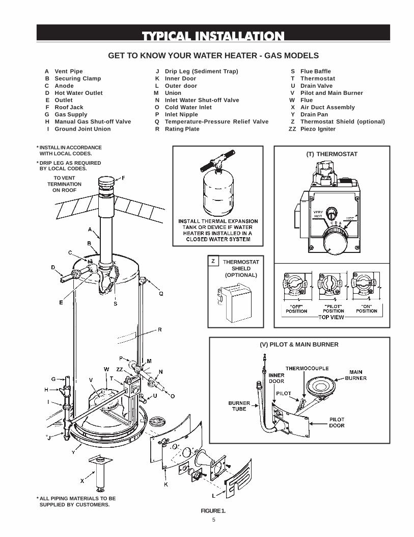
GET TO KNOW YOUR WATER HEATER - GAS MODELS
A Vent PipeB Securing ClampC AnodeD Hot Water OutletE OutletF Roof JackG Gas SupplyH Manual Gas Shut-off ValveI Ground Joint Union
* INSTALL IN ACCORDANCEWITH LOCAL CODES.
* DRIP LEG AS REQUIREDBY LOCAL CODES.
FIGURE 1.
J Drip Leg (Sediment Trap)K Inner DoorL Outer doorM UnionN Inlet Water Shut-off ValveO Cold Water InletP Inlet NippleQ Temperature-Pressure Relief ValveR Rating Plate
S Flue BaffleT ThermostatU Drain ValveV Pilot and Main BurnerW FlueX Air Duct AssemblyY Drain PanZ Thermostat Shield (optional)
ZZ Piezo Igniter
* ALL PIPING MATERIALS TO BESUPPLIED BY CUSTOMERS.
TO VENTTERMINATION
ON ROOF
(T) THERMOSTAT
(V) PILOT & MAIN BURNER
THERMOSTATSHIELD
(OPTIONAL)
Z
6
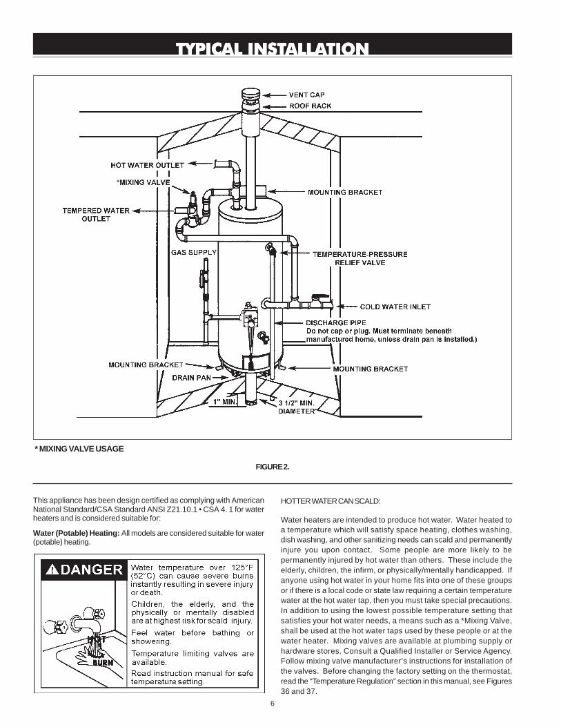
TYPICAL INSTTYPICAL INSTTYPICAL INSTTYPICAL INSTTYPICAL INSTALLAALLAALLAALLAALLATIONTIONTIONTIONTION
FIGURE 2.
* MIXING VALVE USAGE
This appliance has been design certified as complying with AmericanNational Standard/CSA Standard ANSI Z21.10.1 • CSA 4. 1 for waterheaters and is considered suitable for:
Water (Potable) Heating: All models are considered suitable for water(potable) heating.
HOTTER WATER CAN SCALD:
Water heaters are intended to produce hot water. Water heated toa temperature which will satisfy space heating, clothes washing,dish washing, and other sanitizing needs can scald and permanentlyinjure you upon contact. Some people are more likely to bepermanently injured by hot water than others. These include theelderly, children, the infirm, or physically/mentally handicapped. Ifanyone using hot water in your home fits into one of these groupsor if there is a local code or state law requiring a certain temperaturewater at the hot water tap, then you must take special precautions.In addition to using the lowest possible temperature setting thatsatisfies your hot water needs, a means such as a *Mixing Valve,shall be used at the hot water taps used by these people or at thewater heater. Mixing valves are available at plumbing supply orhardware stores. Consult a Qualified Installer or Service Agency.Follow mixing valve manufacturer’s instructions for installation ofthe valves. Before changing the factory setting on the thermostat,read the “Temperature Regulation” section in this manual, see Figures36 and 37.
7
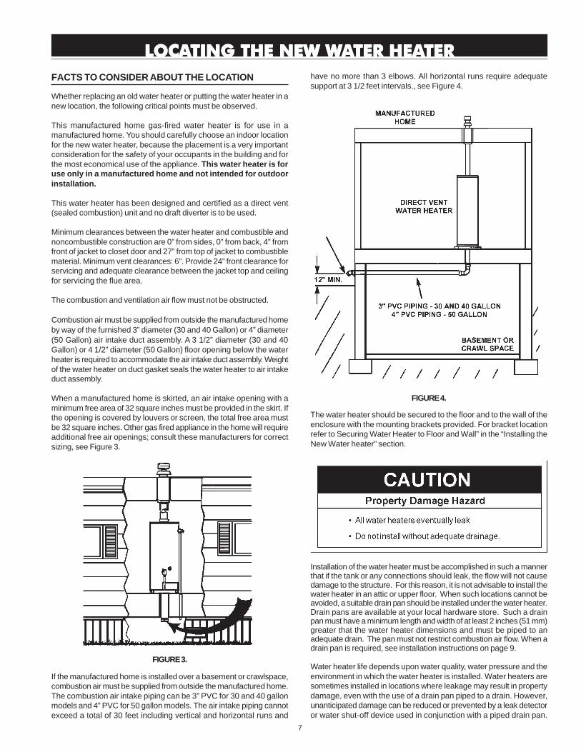
FACTS TO CONSIDER ABOUT THE LOCATION
Whether replacing an old water heater or putting the water heater in anew location, the following critical points must be observed.
This manufactured home gas-fired water heater is for use in amanufactured home. You should carefully choose an indoor locationfor the new water heater, because the placement is a very importantconsideration for the safety of your occupants in the building and forthe most economical use of the appliance. This water heater is foruse only in a manufactured home and not intended for outdoorinstallation.
This water heater has been designed and certified as a direct vent(sealed combustion) unit and no draft diverter is to be used.
Minimum clearances between the water heater and combustible andnoncombustible construction are 0” from sides, 0” from back, 4” fromfront of jacket to closet door and 27” from top of jacket to combustiblematerial. Minimum vent clearances: 6”. Provide 24” front clearance forservicing and adequate clearance between the jacket top and ceilingfor servicing the flue area.
The combustion and ventilation air flow must not be obstructed.
Combustion air must be supplied from outside the manufactured homeby way of the furnished 3” diameter (30 and 40 Gallon) or 4” diameter(50 Gallon) air intake duct assembly. A 3 1/2” diameter (30 and 40Gallon) or 4 1/2” diameter (50 Gallon) floor opening below the waterheater is required to accommodate the air intake duct assembly. Weightof the water heater on duct gasket seals the water heater to air intakeduct assembly.
When a manufactured home is skirted, an air intake opening with aminimum free area of 32 square inches must be provided in the skirt. Ifthe opening is covered by louvers or screen, the total free area mustbe 32 square inches. Other gas fired appliance in the home will requireadditional free air openings; consult these manufacturers for correctsizing, see Figure 3.
FIGURE 3.
If the manufactured home is installed over a basement or crawlspace,combustion air must be supplied from outside the manufactured home.The combustion air intake piping can be 3” PVC for 30 and 40 gallonmodels and 4” PVC for 50 gallon models. The air intake piping cannotexceed a total of 30 feet including vertical and horizontal runs and
LLLLLOCAOCAOCAOCAOCATING THE NEW WTING THE NEW WTING THE NEW WTING THE NEW WTING THE NEW WAAAAATER HEATER HEATER HEATER HEATER HEATERTERTERTERTER
have no more than 3 elbows. All horizontal runs require adequatesupport at 3 1/2 feet intervals., see Figure 4.
FIGURE 4.
The water heater should be secured to the floor and to the wall of theenclosure with the mounting brackets provided. For bracket locationrefer to Securing Water Heater to Floor and Wall” in the “Installing theNew Water heater” section.
Installation of the water heater must be accomplished in such a mannerthat if the tank or any connections should leak, the flow will not causedamage to the structure. For this reason, it is not advisable to install thewater heater in an attic or upper floor. When such locations cannot beavoided, a suitable drain pan should be installed under the water heater.Drain pans are available at your local hardware store. Such a drainpan must have a minimum length and width of at least 2 inches (51 mm)greater that the water heater dimensions and must be piped to anadequate drain. The pan must not restrict combustion air flow. When adrain pan is required, see installation instructions on page 9.
Water heater life depends upon water quality, water pressure and theenvironment in which the water heater is installed. Water heaters aresometimes installed in locations where leakage may result in propertydamage, even with the use of a drain pan piped to a drain. However,unanticipated damage can be reduced or prevented by a leak detectoror water shut-off device used in conjunction with a piped drain pan.
8
These devices are available from some plumbing supply wholesalersand retailers, and detect and react to leakage in various ways:
• Sensors mounted in the drain pan that trigger an alarm or turn offthe incoming water to the water heater when leakage is detected.
• Sensors mounted in the drain pan that turn off the water supply tothe entire home when water is detected in the drain pan.
• Water supply shut-off devices that activate based on the waterpressure differential between the cold water and hot water pipesconnected to the water heater.
• Devices that will turn off the gas supply to a gas water heater whileat the same time shutting off its water supply.
INSTALLATIONS IN AREAS WHERE FLAMMABLE LIQUIDS(VAPORS) ARE LIKELY TO BE PRESENT OR STORED (GARAGES,STORAGE AND UTILITY AREAS, ETC.): Flammable liquids (such asgasoline, solvents, propane [LP or butane, etc.] and other substancessuch as adhesives, etc.) emit flammable vapors which can be ignitedby a gas water heater’s pilot light or main burner. The resulting flashbackand fire can cause death or serious burns to anyone in the area, aswell as property damage. If installation in such areas is your onlyoption, then the installation must be accomplished in a way that the pilotflame and main burner flame are elevated from the floor at least 18inches. While this may reduce the chances of flammable vapors, froma floor spill being ignited, gasoline and other flammable substancesshould never be stored or used in the same room or area containing agas water heater or other open flame or spark producing appliance.NOTE: Flammable vapors may be drawn by air currents from otherareas of the structure to the appliance.
Also, the water heater must be located and/or protected so it is notsubject to physical damage by a moving vehicle.
This water heater must not be installed directly on carpeting. Carpetingmust be protected by metal or wood panel beneath the applianceextending beyond the full width and depth of the appliance by at least3 inches (76.2 mm) in any direction, or if the appliance is installed in an
alcove or closet, the entire floor must be covered by the panel. Failureto heed this warning may result in a fire hazard.
A gas water heater cannot operate properly without the correct amountof air for combustion. Provide ventilation and combustion air by meansof an air intake duct assembly as stated in “Water Heater Installation”.Never obstruct the flow of ventilation air. If you have any doubts orquestions at all, call your gas supplier. Failure to provide the properamount of combustion air can result in a fire or explosion and causedeath, serious bodily injury, or property damage.
If this water heater will be used in beauty shops, barber shops, cleaningestablishments, or self-service laundries with dry cleaning equipment,it is imperative that the water heater or water heaters be installed sothat combustion and ventilation air be taken from outside these areas.Propellants of aerosol sprays and volatile compounds, (cleaners,chlorine based chemicals, refrigerants, etc.) in addition to being highlyflammable in many cases, will also change to corrosive hydrochloricacid when exposed to the combustion products of the water heater.The results can be hazardous, and also cause product failure.
INSULATION BLANKETS
• Install water heater in accordancewith the instruction manual andNFPA 54.
• To avoid injury, combustion andventilation air must be taken fromoutdoors.
• Do not place chemical vaporemitting products near waterheater.
• Do not obstruct water heater airintake with insulating blanket.
• Gas and carbon monoxide detec-tors are available.
• Install water heater in accordancewith the instruction manual.
9
Insulation blankets are available to the general public for external useon gas water heaters but are not necessary with these products. Thepurpose of an insulation blanket is to reduce the standby heat lossencountered with storage tank heaters. Your water heater meets orexceeds the National Appliance Energy Conversation Act standardswith respect to insulation and standby loss requirements, making aninsulation blanket unnecessary.
Should you choose to apply an insulation blanket to this heater, youshould follow these instructions (For identification of componentsmentioned below, see Figure 1). Failure to follow these instructionscan restrict the air flow required for proper combustion, potentiallyresulting in fire, asphyxiation, serious personal injury or death.
• Do not apply insulation to the top of the water heater, as this willinterfere with safe operation of the draft hood.
• Do not cover the outer door, thermostat or temperature & pressurerelief valve.
• Do not allow insulation to come within 2" (50.8 mm) of the floor toprevent blockage of combustion air flow to the burner.
• Do not cover the instruction manual. Keep it on the side of thewater heater or nearby for future reference.
• Do obtain new warning and instruction labels from the manufacturerfor placement on the blanket directly over the existing labels.
• Do inspect the insulation blanket frequently to make certain itdoes not sag, thereby obstructing combustion air flow.
INSTINSTINSTINSTINSTALLING THE NEW WALLING THE NEW WALLING THE NEW WALLING THE NEW WALLING THE NEW WAAAAATER HEATER HEATER HEATER HEATER HEATERTERTERTERTER
WATER HEATER INSTALLATION
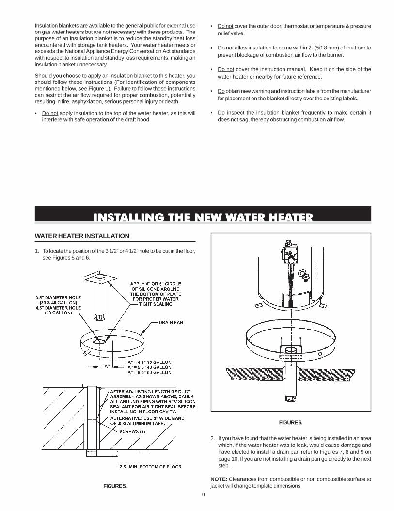
1. To locate the position of the 3 1/2” or 4 1/2” hole to be cut in the floor,see Figures 5 and 6.
FIGURE 5.
FIGURE 6.
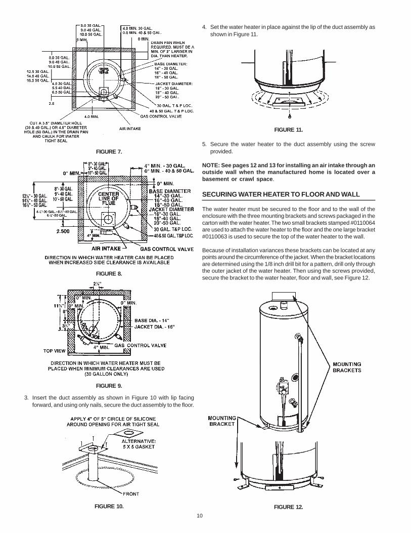
2. If you have found that the water heater is being installed in an areawhich, if the water heater was to leak, would cause damage andhave elected to install a drain pan refer to Figures 7, 8 and 9 onpage 10. If you are not installing a drain pan go directly to the nextstep.
NOTE: Clearances from combustible or non combustible surface tojacket will change template dimensions.
10
FIGURE 7.
FIGURE 8.
FIGURE 9.
3. Insert the duct assembly as shown in Figure 10 with lip facingforward, and using only nails, secure the duct assembly to the floor.
FIGURE 10.
4. Set the water heater in place against the lip of the duct assembly asshown in Figure 11.
FIGURE 11.
5. Secure the water heater to the duct assembly using the screwprovided.
NOTE: See pages 12 and 13 for installing an air intake through anoutside wall when the manufactured home is located over abasement or crawl space.
SECURING WATER HEATER TO FLOOR AND WALL
The water heater must be secured to the floor and to the wall of theenclosure with the three mounting brackets and screws packaged in thecarton with the water heater. The two small brackets stamped #0110064are used to attach the water heater to the floor and the one large bracket#0110063 is used to secure the top of the water heater to the wall.
Because of installation variances these brackets can be located at anypoints around the circumference of the jacket. When the bracket locationsare determined using the 1/8 inch drill bit for a pattern, drill only throughthe outer jacket of the water heater. Then using the screws provided,secure the bracket to the water heater, floor and wall, see Figure 12.
FIGURE 12.
11
ROOF JACK INSTALLATION
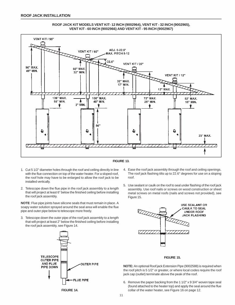
ROOF JACK KIT MODELS VENT KIT- 12 INCH (9002964), VENT KIT - 32 INCH (9002965),VENT KIT - 60 INCH (9002966) AND VENT KIT - 95 INCH (9002967)
FIGURE 13.
1. Cut 5 1/2” diameter holes through the roof and ceiling directly in linewith the flue connection on top of the water heater. For a sloped roof,the roof hole may have to be enlarged to allow the roof jack to beinstalled vertically.
2. Telescope down the flue pipe in the roof jack assembly to a lengththat will project at least 6” below the finished ceiling before installingthe roof jack assembly.
NOTE: Flue pipe joints have silicone seals that must remain in place. Asoapy water solution sprayed around the seal area will enable the fluepipe and outer pipe below to telescope more freely.
3. Telescope down the outer pipe of the roof jack assembly to a lengththat will project at least 2” below the finished ceiling before installingthe roof jack assembly, see Figure 14.
FIGURE 14.
4. Ease the roof jack assembly through the roof and ceiling openings.The roof jack flashing tilts up to 22.6° degrees for use on a slopingroof.
5. Use sealant or caulk on the roof to seal under flashing of the roof jackassembly. Use roof nails or screws on wood construction or sheetmetal screws on metal roofs (nails and screws not provided), seeFigure 15.
FIGURE 15.
NOTE: An optional Roof jack Extension Pipe (9002588) is required whenthe roof pitch is 5 1/2” or greater, or where local codes require the roofjack cap (outlet) terminate above the peak of the roof.
6. Remove the paper backing from the 1 1/2” x 9 3/4” woven tape seal(found attached to the heater top) and apply the seal around the fluecollar of the water heater, see Figure 16 on page 12.
12
FIGURE 16.
7. Extend the flue pipe down close to the water heater flue collar, seeFigure 17.
FIGURE 17.
8. Slide the securing clamp over the bottom of the flue pipe and pull thepipe down over the flue collar. Locate vent securing clamp in topand secure clamp with sheet metal screw. Tighten nut and boltclamp until flue pipe is tight in clamp, see Figure 18.
FIGURE 18.
NOTE: All joints for vent piping between roof jack and water heater aresealed from the manufacturer. No additional sealing of vent pipe isnecessary.
MANUFACTURED HOME INSTALLED OVERBASEMENT OR CRAWLSPACE - AIR INTAKETHROUGH AN OUTSIDE WALL
ALL 30 AND 40 GALLON MODELS
3” PVC Schedule 40 intake air vent piping:Optional Kit No. 9002986 contains a 3” PVC Schedule 40-45° vent capwith screen and two 3” wall collars.
ALL 50 GALLON MODELS
4” PVC Schedule 40 intake air vent piping:Optional Kit no. 9002987 contains a 4” PVC Schedule 40-45° vent capwith screen and two 4” wall collars.
ALL MODELS
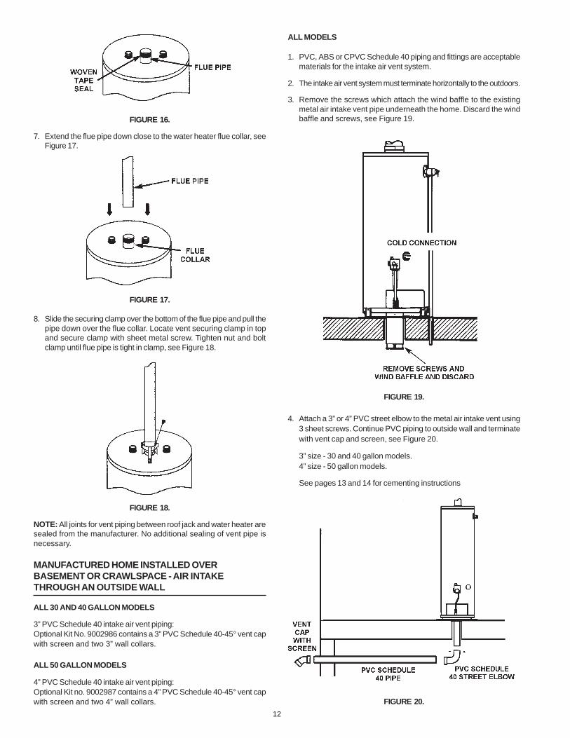
1. PVC, ABS or CPVC Schedule 40 piping and fittings are acceptablematerials for the intake air vent system.
2. The intake air vent system must terminate horizontally to the outdoors.
3. Remove the screws which attach the wind baffle to the existingmetal air intake vent pipe underneath the home. Discard the windbaffle and screws, see Figure 19.
FIGURE 19.
4. Attach a 3” or 4” PVC street elbow to the metal air intake vent using3 sheet screws. Continue PVC piping to outside wall and terminatewith vent cap and screen, see Figure 20.
3” size - 30 and 40 gallon models.4” size - 50 gallon models.
See pages 13 and 14 for cementing instructions
FIGURE 20.

13
NOTE: Vent cap must be located a minimum of 12” above the ground.
5. Vertical and horizontal runs must be securely supported at 3 1/2Foot intervals, see Figure 21.
FIGURE 21.
6. The intake air vent piping can be installed with no more than 3elbows, see Figure 22.
FIGURE 22.
CUTTING OPENING THROUGH AN OUTSIDE WALL AND COLLARINSTALLATION
Determine the location of the opening in the wall and cut a 3 3/4” hole(30 & 40 Gallon) or 4 3/4” hole (50 Gallon) through an outside wall.
The 3” or 4” PVC, ABS or CPVC Schedule 40 vent pipe can be run fromthe water heater through the wall or from the wall to the water heater,whichever is most convenient. The vent pipe must extend a minimum of1 1/2” through the exterior wall. Note that the inside collar must beslipped over the vent piping before locating the pipe through the wall.Before securing the inside and outside collars to the wall, use a siliconesealer between pipe and opening to insure a water and air tight seal,see Figure 23.
INSTALLATION SHOWING USE OF PVC, ABS OR CPVC PIPE
FIGURE 23.
NOTE: Wall collars are for aesthetic purposes and are not required forthe heater to operate.
CEMENTING PVC, ABS OR CPVC PIPE AND FITTINGS
Read and observe all safety information printed on primer, cleaner, andcement containers.
Primer, cleaner, and cements are extremely flammable. They are harmfulor fatal if swallowed. The vapors are harmful. They may irritate eyesand skin and can be absorbed through the skin.
Always store primer, cleaner, and cements in cool, dry, well ventilatedplaces. Keep containers closed. Use them in well ventilated areas.Wear impervious clothing while handling. Do not smoke, eat, or drinkwhile handling. Wash thoroughly after handling and before eating.Wear eye protection when handling. If swallowed, drink water, do notinduce vomitting, and call a physician or poison control centerimmediately. If inhaled, get fresh air and seek medical attention if illfeelings persist. In case of eye and skin contact, immediately flush withplenty of water for 15 minuttes and seek medical attention if irritationpersists. KEEP OUT OF REACH OF CHILDREN.
All primers, cleaners, and cements must meet all local codes andapplicable standards of the American Society For Testing MaterialsStandards.
Before using primers, cleaners and cements, stir or shake, makingsure contents are liquid. Do not use if found to be lumpy or jelly-like.
1. Cut pipe ends squarely removing all burrs and dirt.
2. Dry fit pipe and fittings to be connected for proper fit.
3. Clean pipe and fitting with primer/cleaner.
4. Apply a thin coat of cement to fitting, avoiding puddling inside.
5. Apply a liberal coat of cement to pipe leaving no voids.
6. QUICKLY assemble parts while cement is fluid! If you wait too long,recoat pipes.
7. Push pipe completely into socket of fitting, turning as it goes until itbottoms.
8. Hold pipe and fitting together for 30 seconds. Then carefully cleanoff excess with a cloth. Allow connections a sufficient time to curebefore distrurbing.
9. Remember that vent pipes must be adequately and securelysupported.
14
APPROXIMATE SETTING TIME FOR 2 1/2” TO 4” PIPE JOINTS
MOVEMENT COMPLETEOF JOINT SET
90°F TO 150°F 3/4HR. 8 HRS.50°F TO 90°F 1 HR. 15 HRS.0°f TO 50°F 1 1/3 HR. 18 HRS.
WATER PIPING
HOTTER WATER CAN SCALD:Water heaters are intended to produce hot water. Water heated to atemperature which will satisfy space heating, clothes washing, dishwashing, cleaning and other sanitizing needs can scald andpermanently injure you upon contact. Some people are more likely tobe permanently injured by hot water than others. These include theelderly, children, the infirm, or physically/mentally handicapped. Ifanyone using hot water in your home fits into one of these groups orif there is a local code or state law requiring a certain temperaturewater at the hot water tap, then you must take special precautions. Inaddition to using the lowest possible temperature setting that satisfiesyour hot water needs, a means such as a *mixing valve, shall beused at the hot water taps used by these people or at the waterheater, see Figure 2. Valves for reducing point of use temperature bymixing cold and hot water are also available. Consult a QualifiedInstaller or Service Agency. Follow manufacturer’s instructions forinstallation of the valves. Before changing the factory setting on thethermostat, read the “Temperature Regulation” section in this manual.
This water heater shall not be connected to any heating systems orcomponent(s) used with a non-potable water heating appliance.
Toxic chemicals, such as those used for boiler treatment shall not beintroduced into this system.
Water supply systems may, because of such events as high linepressure, frequent cut-offs, the effects of water hammer amongothers, have installed devices such as pressure reducing valves, checkvalves, back flow preventers, etc. to control these types of problems.When these devices are not equipped with an internal by-pass, and noother measures are taken, the devices cause the water system to beclosed. As water is heated, it expands (thermal expansion) and closedsystems do not allow for the expansion of heated water.
The water within the water heater tank expands as it is heated andincreases the pressure of the water system. If the relieving point ofthe water heater’s temperature-pressure relief valve is reached, thevalve will relieve the excess pressure. The temperature-pressurerelief valve is not intended for the constant relief of thermalexpansion. This is an unacceptable condition and must be corrected.It is recommended that any devices installed which could create aclosed system have a by-pass and/or the system have an expansiontank to relieve the pressure built by thermal expansion in the watersystem. Expansion tanks are available for ordering through a localplumbing contractor. Contact the local water supplier and/or a serviceagency for assistance in controlling these situations.
NOTE: To protect against untimely corrosion of hot and coldwater fittings, it is strongly recommended that di-electricunions or couplings be installed on this water heater whenconnected to copper pipe.
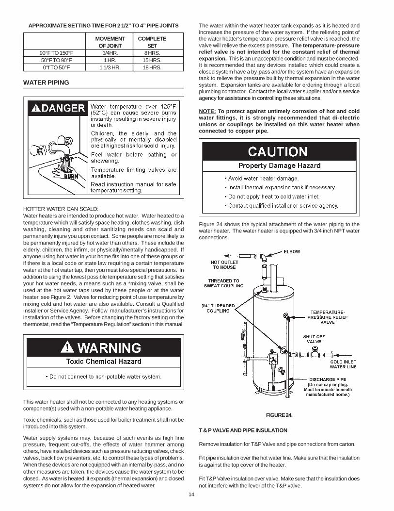
Figure 24 shows the typical attachment of the water piping to thewater heater. The water heater is equipped with 3/4 inch NPT waterconnections.
FIGURE 24.
T & P VALVE AND PIPE INSULATION
Remove insulation for T&P Valve and pipe connections from carton.
Fit pipe insulation over the hot water line. Make sure that the insulationis against the top cover of the heater.
Fit T&P Valve insulation over valve. Make sure that the insulation doesnot interfere with the lever of the T&P valve.
15
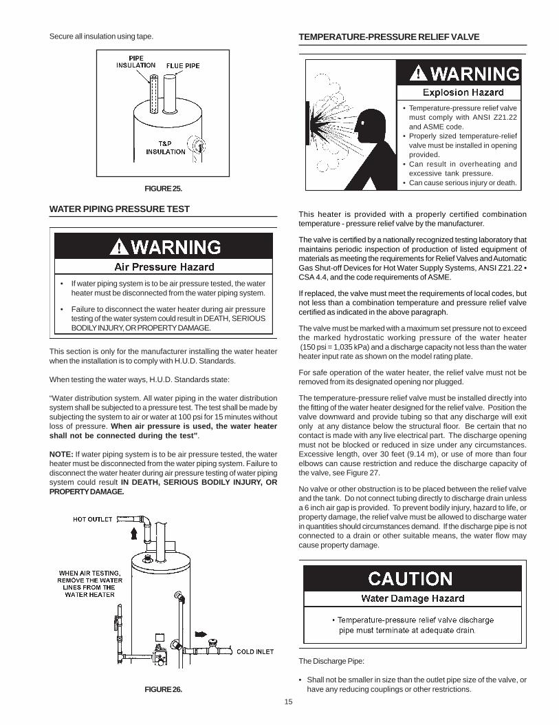
Secure all insulation using tape.
FIGURE 25.
WATER PIPING PRESSURE TEST
This section is only for the manufacturer installing the water heaterwhen the installation is to comply with H.U.D. Standards.
When testing the water ways, H.U.D. Standards state:
“Water distribution system. All water piping in the water distributionsystem shall be subjected to a pressure test. The test shall be made bysubjecting the system to air or water at 100 psi for 15 minutes withoutloss of pressure. When air pressure is used, the water heatershall not be connected during the test”.
NOTE: If water piping system is to be air pressure tested, the waterheater must be disconnected from the water piping system. Failure todisconnect the water heater during air pressure testing of water pipingsystem could result IN DEATH, SERIOUS BODILY INJURY, ORPROPERTY DAMAGE.
FIGURE 26.
TEMPERATURE-PRESSURE RELIEF VALVE
This heater is provided with a properly certified combinationtemperature - pressure relief valve by the manufacturer.
The valve is certified by a nationally recognized testing laboratory thatmaintains periodic inspection of production of listed equipment ofmaterials as meeting the requirements for Relief Valves and AutomaticGas Shut-off Devices for Hot Water Supply Systems, ANSI Z21.22 •CSA 4.4, and the code requirements of ASME.
If replaced, the valve must meet the requirements of local codes, butnot less than a combination temperature and pressure relief valvecertified as indicated in the above paragraph.
The valve must be marked with a maximum set pressure not to exceedthe marked hydrostatic working pressure of the water heater (150 psi = 1,035 kPa) and a discharge capacity not less than the waterheater input rate as shown on the model rating plate.
For safe operation of the water heater, the relief valve must not beremoved from its designated opening nor plugged.
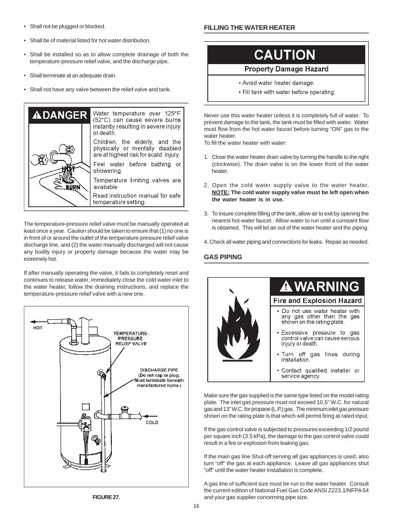
The temperature-pressure relief valve must be installed directly intothe fitting of the water heater designed for the relief valve. Position thevalve downward and provide tubing so that any discharge will exitonly at any distance below the structural floor. Be certain that nocontact is made with any live electrical part. The discharge openingmust not be blocked or reduced in size under any circumstances.Excessive length, over 30 feet (9.14 m), or use of more than fourelbows can cause restriction and reduce the discharge capacity ofthe valve, see Figure 27.
No valve or other obstruction is to be placed between the relief valveand the tank. Do not connect tubing directly to discharge drain unlessa 6 inch air gap is provided. To prevent bodily injury, hazard to life, orproperty damage, the relief valve must be allowed to discharge waterin quantities should circumstances demand. If the discharge pipe is notconnected to a drain or other suitable means, the water flow maycause property damage.
The Discharge Pipe:
• Shall not be smaller in size than the outlet pipe size of the valve, orhave any reducing couplings or other restrictions.
• If water piping system is to be air pressure tested, the waterheater must be disconnected from the water piping system.
• Failure to disconnect the water heater during air pressuretesting of the water system could result in DEATH, SERIOUSBODILY INJURY, OR PROPERTY DAMAGE.
• Temperature-pressure relief valvemust comply with ANSI Z21.22and ASME code.
• Properly sized temperature-reliefvalve must be installed in openingprovided.
• Can result in overheating andexcessive tank pressure.
• Can cause serious injury or death.
16
• Shall not be plugged or blocked.
• Shall be of material listed for hot water distribution.
• Shall be installed so as to allow complete drainage of both thetemperature-pressure relief valve, and the discharge pipe.
• Shall terminate at an adequate drain.
• Shall not have any valve between the relief valve and tank.
The temperature-pressure relief valve must be manually operated atleast once a year. Caution should be taken to ensure that (1) no one isin front of or around the outlet of the temperature-pressure relief valvedischarge line, and (2) the water manually discharged will not causeany bodily injury or property damage because the water may beextremely hot.
If after manually operating the valve, it fails to completely reset andcontinues to release water, immediately close the cold water inlet tothe water heater, follow the draining instructions, and replace thetemperature-pressure relief valve with a new one.
FIGURE 27.
FILLING THE WATER HEATER
Never use this water heater unless it is completely full of water. Toprevent damage to the tank, the tank must be filled with water. Watermust flow from the hot water faucet before turning “ON” gas to thewater heater.To fill the water heater with water:
1. Close the water heater drain valve by turning the handle to the right(clockwise). The drain valve is on the lower front of the waterheater.
2. Open the cold water supply valve to the water heater.NOTE: The cold water supply valve must be left open whenthe water heater is in use.
3. To insure complete filling of the tank, allow air to exit by opening thenearest hot water faucet. Allow water to run until a constant flowis obtained. This will let air out of the water heater and the piping.
4. Check all water piping and connections for leaks. Repair as needed.
GAS PIPING
Make sure the gas supplied is the same type listed on the model ratingplate. The inlet gas pressure must not exceed 10.5” W.C. for naturalgas and 13” W.C. for propane (L.P.) gas. The minimum inlet gas pressureshown on the rating plate is that which will permit firing at rated input.
If the gas control valve is subjected to pressures exceeding 1/2 poundper square inch (3.5 kPa), the damage to the gas control valve couldresult in a fire or explosion from leaking gas.
If the main gas line Shut-off serving all gas appliances is used, alsoturn “off” the gas at each appliance. Leave all gas appliances shut“off” until the water heater installation is complete.
A gas line of sufficient size must be run to the water heater. Consultthe current edition of National Fuel Gas Code ANSI Z223.1/NFPA 54and your gas supplier concerning pipe size.
17
There must be:
• A readily accessible manual shut off valve in the gas supply lineserving the water heater, and
• A drip leg (sediment trap) ahead of the gas control valve to helpprevent dirt and foreign materials from entering the gas control valve.
• A flexible gas connector or a ground joint union between the shutoff valve and control valve to permit servicing of the unit.
Be sure to check all the gas piping for leaks before lighting the waterheater. Use a soapy water solution, not a match or open flame. Rinseoff soapy solution and wipe dry.
When installed at elevations above 5,000 feet (1524 m), input ratingshould be reduced at the rate of 4 percent for each 1,000 feet (305 m)above sea level which requires replacement of the burner orifice inaccordance with National Fuel Gas Code ANSI Z223.1/NFPA 54. Contactyour local gas supplier for further information.
Failure to replace the standard orifice with a high altitude orifice wheninstalled could result in improper and inefficient operation of theappliance, producing carbon monoxide gas in excess of safe limits,which could result in serious injury or death. Contact your gas supplierfor any specific changes which may be required in your area.
Use pipe joint compound or teflon tape marked as being resistant to theaction of petroleum [Propane (L.P.)] gases.
The appliance and its gas connection must be leak tested before placingthe appliance in operation.
The appliance and its individual Shut-off valve shall be disconnectedfrom the gas supply piping system during any pressure testing of thatsystem at test pressures in excess of 1/2 pound per square inch(3.5 kPa). It shall be isolated from the gas supply piping system byclosing its individual manual Shut-off valve during any pressure testingof the gas supply piping system at test pressures equal to or less than1/2 pound per square inch (3.5 kPa).
Connecting the gas piping to the gas control valve of the water heatercan be accomplished by either of the two methods shown inFigures 28, 29 and 30.
SEDIMENT TRAPS
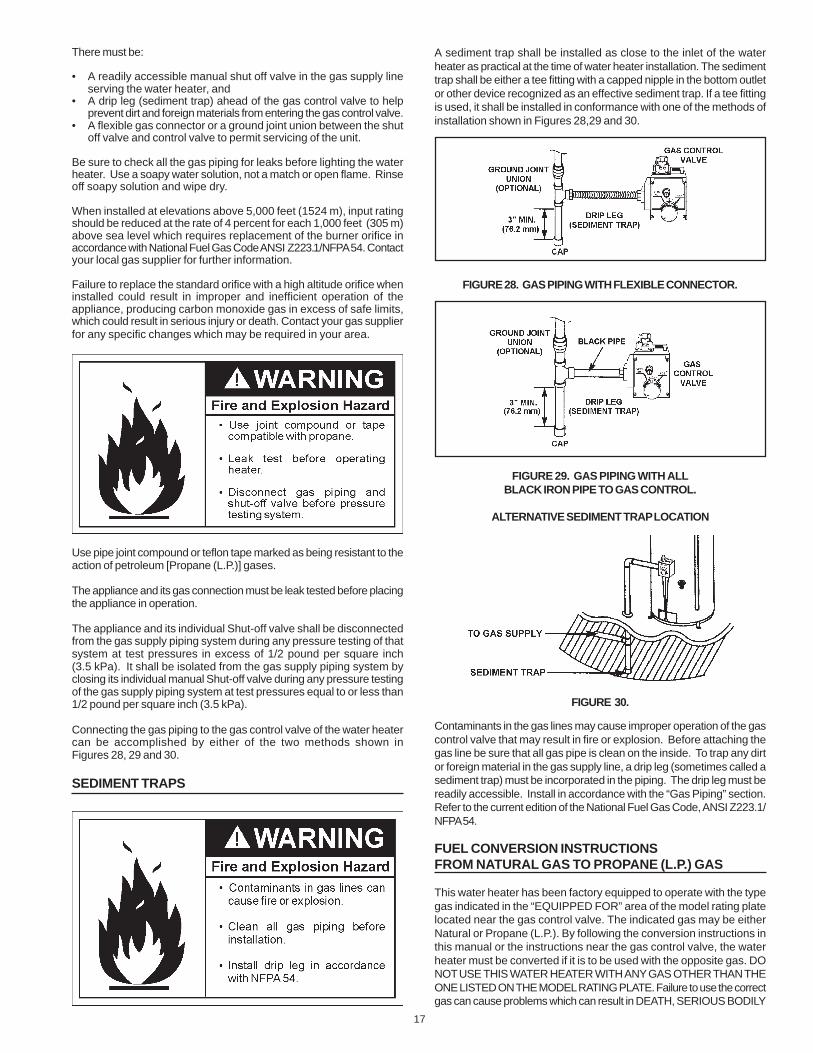
A sediment trap shall be installed as close to the inlet of the waterheater as practical at the time of water heater installation. The sedimenttrap shall be either a tee fitting with a capped nipple in the bottom outletor other device recognized as an effective sediment trap. If a tee fittingis used, it shall be installed in conformance with one of the methods ofinstallation shown in Figures 28,29 and 30.
FIGURE 28. GAS PIPING WITH FLEXIBLE CONNECTOR.
FIGURE 29. GAS PIPING WITH ALLBLACK IRON PIPE TO GAS CONTROL.
ALTERNATIVE SEDIMENT TRAP LOCATION
FIGURE 30.
Contaminants in the gas lines may cause improper operation of the gascontrol valve that may result in fire or explosion. Before attaching thegas line be sure that all gas pipe is clean on the inside. To trap any dirtor foreign material in the gas supply line, a drip leg (sometimes called asediment trap) must be incorporated in the piping. The drip leg must bereadily accessible. Install in accordance with the “Gas Piping” section.Refer to the current edition of the National Fuel Gas Code, ANSI Z223.1/NFPA 54.
FUEL CONVERSION INSTRUCTIONSFROM NATURAL GAS TO PROPANE (L.P.) GAS
This water heater has been factory equipped to operate with the typegas indicated in the “EQUIPPED FOR” area of the model rating platelocated near the gas control valve. The indicated gas may be eitherNatural or Propane (L.P.). By following the conversion instructions inthis manual or the instructions near the gas control valve, the waterheater must be converted if it is to be used with the opposite gas. DONOT USE THIS WATER HEATER WITH ANY GAS OTHER THAN THEONE LISTED ON THE MODEL RATING PLATE. Failure to use the correctgas can cause problems which can result in DEATH, SERIOUS BODILY
18
INJURY, OR PROPERTY DAMAGE. If you have any questions or doubtsconsult your gas supplier or gas company.
Read and follow detailed conversion instructions located on the waterheater and also in the instruction manual in their entirety before startingthe conversion.
Conversion kit with necessary parts are in a bag attached to the drainvalve.
FOR 30 GALLON HEATER:
Orifice size: #40 for Natural / #52 for Propane (L.P.),if converted - Propane Rate: 30,000 BTU.
FOR 40 GALLON HEATER:
Orifice size: #38 for Natural / #51 for Propane (L.P.),if converted - Propane Rate: 32,000 BTU.
FOR 50 GALLON HEATER:
Orifice size: #35 for Natural / #51 for Propane (L.P.),if converted - Propane Rate: 38,000 BTU.
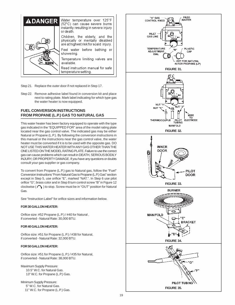
Step 1. Turn gas control knob “A” to “PILOT”. Depress and turn “OFF”,see Figure 31 page 19.
Step 2. Remove outer and inner access doors from water heater.
Step 3. Remove burner assembly from water heater controlby first removing 6 screws holding inner door to heater, thenloosening 3/4” nut “H” holding burner assembly to control, seefigures 32 and 33. Loosen pilot tube nut “J” and thermocouplenut “K” at control. Disconnect wire to Piezo Igniter.
Step 4. Remove screws “D” disengaging manifold from burner, seeFigure 34 page 19.
Step 5. Remove orifice “E”, see Figure 34 page 19 using 3/8” wrench.Install orifice marked “L.P.” found in the bag into manifold.Tighten securely. Secure burner to manifold withscrews “D”.
Step 6. Loosen pilot tube nut “F”, see Figure 35 page 19. Removeorifice “G” and replace with red colored orifice found in bag.Reinstall nut “F” and tighten securely.
Step 7. Make sure all connections are tightened securely, and reinstallburner assembly into water heater. Position end of manifoldinside bracket as shown in Figure 34 page 19. Reinstall manifoldinto control and tighten 3/4” nut (“H”) securely. Recheck to see thatend of manifold is still inside bracket as shown in Figure 34page 19. Reinstall pilot tubing and thermocouple into control, seeFigure 32 page 15. Connect wire to Piezo Igniter. Reinstall innerdoor using the 6 screws removed in Step 3.
Step 8. Place screwdriver in slot “B”, see Figure 31 page 19. Depressand turn counterclockwise ( ) to stop. Control screwmust be in “IN” position for propane (L.P.) gas and in “OUT”position for natural gas. STOP! Read label “For Your Safety”located on your water heater.
Step 9. Set the thermostat to lowest setting by turning the watertemperature dial clockwise, ( ) to its lowest temperaturesetting (with arrow on dial) as shown.
Step 10. Turn gas control knob clockwise to “OFF” position.Knob cannot be turned from “PILOT” to “OFF” unless knob isdepressed slightly. DO NOT FORCE.
Step 11. Wait five minutes to clear out any gas. If you then smellgas, STOP! Follow “B” in the safety information on “ForYour Safety” label. If you don’t smell gas, got to the nextstep.
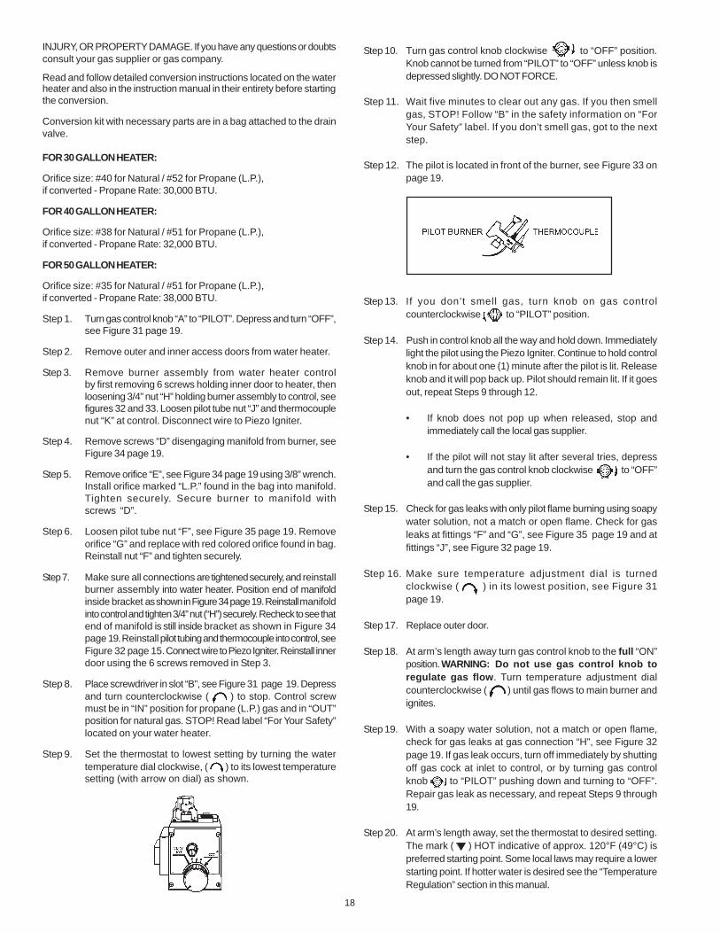
Step 12. The pilot is located in front of the burner, see Figure 33 onpage 19.
Step 13. If you don’t smell gas, turn knob on gas controlcounterclockwise to “PILOT” position.
Step 14. Push in control knob all the way and hold down. Immediatelylight the pilot using the Piezo Igniter. Continue to hold controlknob in for about one (1) minute after the pilot is lit. Releaseknob and it will pop back up. Pilot should remain lit. If it goesout, repeat Steps 9 through 12.
• If knob does not pop up when released, stop andimmediately call the local gas supplier.
• If the pilot will not stay lit after several tries, depressand turn the gas control knob clockwise to “OFF”and call the gas supplier.
Step 15. Check for gas leaks with only pilot flame burning using soapywater solution, not a match or open flame. Check for gasleaks at fittings “F” and “G”, see Figure 35 page 19 and atfittings “J”, see Figure 32 page 19.
Step 16. Make sure temperature adjustment dial is turnedclockwise ( ) in its lowest position, see Figure 31page 19.
Step 17. Replace outer door.
Step 18. At arm’s length away turn gas control knob to the full “ON”position. WARNING: Do not use gas control knob toregulate gas flow. Turn temperature adjustment dialcounterclockwise ( ) until gas flows to main burner andignites.
Step 19. With a soapy water solution, not a match or open flame,check for gas leaks at gas connection “H”, see Figure 32page 19. If gas leak occurs, turn off immediately by shuttingoff gas cock at inlet to control, or by turning gas controlknob to “PILOT” pushing down and turning to “OFF”.Repair gas leak as necessary, and repeat Steps 9 through19.
Step 20. At arm’s length away, set the thermostat to desired setting.The mark ( ) HOT indicative of approx. 120°F (49°C) ispreferred starting point. Some local laws may require a lowerstarting point. If hotter water is desired see the “TemperatureRegulation” section in this manual.
19
Step 21. Replace the outer door if not replaced in Step 17.
Step 22. Remove adhesive label found in conversion kit and placenext to rating plate. Mark label indicating for which type gasthe water heater is now equipped.
FUEL CONVERSION INSTRUCTIONSFROM PROPANE (L.P.) GAS TO NATURAL GAS
This water heater has been factory equipped to operate with the typegas indicated in the “EQUIPPED FOR” area of the model rating platelocated near the gas control valve. The indicated gas may be eitherNatural or Propane (L.P.). By following the conversion instructions inthis manual or the instructions near the gas control valve, the waterheater must be converted if it is to be used with the opposite gas. DONOT USE THIS WATER HEATER WITH ANY GAS OTHER THAN THEONE LISTED ON THE MODEL RATING PLATE. Failure to use the correctgas can cause problems which can result in DEATH, SERIOUS BODILYINJURY, OR PROPERTY DAMAGE. If you have any questions or doubtsconsult your gas supplier or gas company.
To convert from Propane (L.P.) gas to Natural gas, follow the “Fuel”Conversion Instructions “From Natural Gas to Propane (L.P.) Gas” sectionexcept in Step 5, use orifice “E”, marked “NAT.”. In Step 6 use pilotorifice “G”, brass color and in Step 8 turn control screw “B” in Figure 12clockwise ( ) to stop. Screw must be in “OUT” position for NaturalGas.
See “Instruction Label” for orifice sizes and information below.
FOR 30 GALLON HEATER:
Orifice size: #52 Propane (L.P.) / #40 for Natural ,if converted - Natural Rate: 30,000 BTU.
FOR 40 GALLON HEATER:
Orifice size: #51 for Propane (L.P.) / #38 for Natural,if converted - Natural Rate: 32,000 BTU.
FOR 50 GALLON HEATER:
Orifice size: #51 for Propane (L.P.) / #35 for Natural,if converted - Natural Rate: 38,000 BTU.
Maximum Supply Pressure:10.5” W.C. for Natural Gas.13” W.C. for Propane (L.P.) Gas.
Minimum Supply Pressure: 5” W.C. for Natural Gas. 11” W.C. for Propane (L.P.) Gas.
FIGURE 33.
FIGURE 34.
FIGURE 35.
FIGURE 31.
FIGURE 32.
20
21
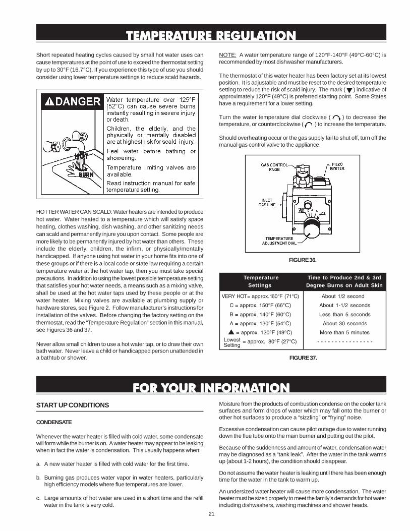
VERY HOT= approx. 160°F (71°C) About 1/2 second
C = approx. 150°F (66°C) About 1-1/2 seconds
B = approx. 140°F (60°C) Less than 5 seconds
A = approx. 130°F (54°C) About 30 seconds
= approx. 120°F (49°C) More than 5 minutes
= approx. 80°F (27°C) - - - - - - - - - - - - - - - -
FIGURE 37.
FOR YFOR YFOR YFOR YFOR YOUR INFORMAOUR INFORMAOUR INFORMAOUR INFORMAOUR INFORMATIONTIONTIONTIONTION
START UP CONDITIONS
CONDENSATE
Whenever the water heater is filled with cold water, some condensatewill form while the burner is on. A water heater may appear to be leakingwhen in fact the water is condensation. This usually happens when:
a. A new water heater is filled with cold water for the first time.
b. Burning gas produces water vapor in water heaters, particularlyhigh efficiency models where flue temperatures are lower.
c. Large amounts of hot water are used in a short time and the refillwater in the tank is very cold.
NOTE: A water temperature range of 120°F-140°F (49°C-60°C) isrecommended by most dishwasher manufacturers.
The thermostat of this water heater has been factory set at its lowestposition. It is adjustable and must be reset to the desired temperaturesetting to reduce the risk of scald injury. The mark ( ) indicative ofapproximately 120°F (49°C) is preferred starting point. Some Stateshave a requirement for a lower setting.
Turn the water temperature dial clockwise ( ) to decrease thetemperature, or counterclockwise ( ) to increase the temperature.
Should overheating occur or the gas supply fail to shut off, turn off themanual gas control valve to the appliance.
FIGURE 36.
Temperature Time to Produce 2nd & 3rdSettings Degree Burns on Adult Skin
Short repeated heating cycles caused by small hot water uses cancause temperatures at the point of use to exceed the thermostat settingby up to 30°F (16.7°C). If you experience this type of use you shouldconsider using lower temperature settings to reduce scald hazards.
HOTTER WATER CAN SCALD: Water heaters are intended to producehot water. Water heated to a temperature which will satisfy spaceheating, clothes washing, dish washing, and other sanitizing needscan scald and permanently injure you upon contact. Some people aremore likely to be permanently injured by hot water than others. Theseinclude the elderly, children, the infirm, or physically/mentallyhandicapped. If anyone using hot water in your home fits into one ofthese groups or if there is a local code or state law requiring a certaintemperature water at the hot water tap, then you must take specialprecautions. In addition to using the lowest possible temperature settingthat satisfies your hot water needs, a means such as a mixing valve,shall be used at the hot water taps used by these people or at thewater heater. Mixing valves are available at plumbing supply orhardware stores, see Figure 2. Follow manufacturer’s instructions forinstallation of the valves. Before changing the factory setting on thethermostat, read the “Temperature Regulation” section in this manual,see Figures 36 and 37.
Never allow small children to use a hot water tap, or to draw their ownbath water. Never leave a child or handicapped person unattended ina bathtub or shower.
TEMPERATEMPERATEMPERATEMPERATEMPERATURE REGULATURE REGULATURE REGULATURE REGULATURE REGULATIONTIONTIONTIONTION
Moisture from the products of combustion condense on the cooler tanksurfaces and form drops of water which may fall onto the burner orother hot surfaces to produce a “sizzling” or “frying” noise.
Excessive condensation can cause pilot outage due to water runningdown the flue tube onto the main burner and putting out the pilot.
Because of the suddenness and amount of water, condensation watermay be diagnosed as a “tank leak”. After the water in the tank warmsup (about 1-2 hours), the condition should disappear.
Do not assume the water heater is leaking until there has been enoughtime for the water in the tank to warm up.
An undersized water heater will cause more condensation. The waterheater must be sized properly to meet the family’s demands for hot waterincluding dishwashers, washing machines and shower heads.
LowestSetting

22
Excessive condensation may be noticed during the winter and earlyspring months when incoming water temperatures are at their lowest.
Good venting is essential for a gas fired water heater to operate properlyas well as to carry away products of combustion and water vapor.
SMOKE / ODOR
It is not uncommon to experience a small amount of smoke and odorduring the initial start-up. This is due to burning off of oil from metal parts,and will disappear in a short while.
THERMAL EXPANSION
Water supply systems may, because of such events as high linepressure, frequent cut-offs, the effects of water hammer amongothers, have installed devices such as pressure reducing valves, checkvalves, back flow preventers, etc. to control these types of problems.When these devices are not equipped with an internal by-pass, and noother measures are taken, the devices cause the water system to beclosed. As water is heated, it expands (thermal expansion) and closedsystems do not allow for the expansion of heated water.
The water within the water heater tank expands as it is heated andincreases the pressure of the water system. If the relieving point ofthe water heater’s temperature-pressure relief valve is reached, thevalve will relieve the excess pressure. The temperature-pressurerelief valve is not intended for the constant relief of thermalexpansion. This is an unacceptable condition and must be corrected.It is recommended that any devices installed which could create aclosed system have a by-pass and/or the system have an expansiontank or device to relieve the pressure built by thermal expansion in thewater system. Expansion tanks are available for ordering through alocal plumbing contractor. Contact the local water heater supplier orservice agency for assistance in controlling these situations.
STRANGE SOUNDS
Possible noises due to expansion and contraction of some metal partsduring periods of heat-up and cool-down do not necessarily representharmful or dangerous conditions.
Condensation causes sizzling and popping within the burner area duringheating and cooling periods and should be considered normal. See“Condensation” in this section.
OPERATIONAL CONDITIONS
SMELLY WATER
In each water heater there is installed at least one anode rod (seeparts sections) for corrosion protection of the tank. Certain waterconditions will cause a reaction between this rod and the water. The
most common complaint associated with the anode rod is one of a“rotten egg smell” in the hot water. This odor is derived from hydrogensulfide gas dissolved in the water. The smell is the result of fourfactors which must all be present for the odor to develop:
a. A concentration of sulfate in the supply water.
b. Little or no dissolved oxygen in the water.
c. A sulfate reducing bacteria which has accumulated within the waterheater (this harmless bacteria is nontoxic to humans).
d. An excess of active hydrogen in the tank. This is caused by thecorrosion protective action of the anode.
Smelly water may be eliminated or reduced in some water heatermodels by replacing the anode(s) with one of less active material, andthen chlorinating the water heater tank and all hot water lines. Contactthe local water heater supplier or service agency for further informationconcerning an Anode Replacement Kit and this chlorination treatment.
If the smelly water persists after the anode replacement and chlorinationtreatment, we can only suggest that chlorination or aeration of thewater supply be considered to eliminate the water problem.
Do not remove the anode leaving the tank unprotected. Bydoing so, all warranty on the water heater tank is voided.
“AIR” IN HOT WATER FAUCETS
HYDROGEN GAS: Hydrogen gas can be produced in a hot watersystem that has not been used for a long period of time (generally twoweeks or more). Hydrogen gas is extremely flammable and explosive.To prevent the possibility of injury under these conditions, werecommend the hot water faucet, located farthest away, be openedfor several minutes before any electrical appliances which areconnected to the hot water system are used (such as a dishwasher orwashing machine). If hydrogen gas is present, there will probably bean unusual sound similar to air escaping through the pipe as the hotwater faucet is opened. There must be no smoking or open flame nearthe faucet at the time it is open.
HIGH WATER TEMPERATURE SHUT OFF SYSTEM
This water heater is equipped with an automatic gas Shut-off system.This system works when high water temperatures are present. Turn“OFF” the entire gas supply to the water heater. The high temperatureShut-off is built into the gas control valve. It is non-resettable. If thehigh temperature Shut-off activates, the gas control valve must bereplaced. Contact your gas supplier or service agency.

23
VENTING SYSTEM INSPECTION
At least once a year a visual inspection should be made of the ventingsystem. You should look for:
1. Obstructions which could cause improper venting. The combustionand ventilation air flow must not be obstructed.
2. Damage or deterioration which could cause improper venting orleakage of combustion products.
3. Rusted flakes around top of water heater.
Be sure the vent piping is properly connected to prevent escape ofdangerous flue gasses which could cause deadly asphyxiation.
Obstructions and deteriorated vent systems may present serious healthrisk or asphyxiation.
Chemical vapor corrosion of the flue and vent system may occur if airfor combustion contains certain chemical vapors. Spray can propellants,cleaning solvents, refrigerator and air conditioner refrigerants,swimming pool chemicals, calcium and sodium chloride, waxes, bleachand process chemicals are typical compounds which are potentiallycorrosive.
If after inspection of the vent system you found sooting or deterioration,something is wrong. Call the local gas utility to correct the problem andclean or replace the flue and venting before resuming operation of thewater heater.
BURNER INSPECTION
Flood damage to a water heater may not be readily visible or immediatelydetectable. However, over a period of time a flooded water heater willcreate dangerous conditions which can cause DEATH, SERIOUSBODILY INJURY, OR PROPERTY DAMAGE. Contact a qualified installeror service agency to replace a flooded water heater. Do not attempt torepair the unit! It must be replaced!
At least once a year a visual inspection should be made of the mainburner and pilot burner, see Figure 38.
PERIODIC MAINTENANCEPERIODIC MAINTENANCEPERIODIC MAINTENANCEPERIODIC MAINTENANCEPERIODIC MAINTENANCEYou should check for sooting. Soot is not normal and will impair propercombustion.
Soot build-up indicates a problem that requires correction before furtheruse. Turn “OFF” gas to water heater and leave off until repairs aremade, because failure to correct the cause of the sooting can result ina fire causing death, serious injury, or property damage.
FIGURE 38.
BURNER CLEANING
In the event your burner needs cleaning, follow these instructions:
If inspection of the burner shows that cleaning is required, turn the gascontrol knob clockwise ( ) to the “OFF” position, depressing slightly.
NOTE: The knob cannot be turned from “PILOT” to “OFF” unlessknob is depressed slightly. DO NOT FORCE.
The burner needs to be removed for cleaning. Call a service agency toremove and clean the burner and correct the problem that required theburner to be cleaned.
HOUSEKEEPING
Vacuum around base of water heater for dust, dirt, and lint on a regularbasis.
INSTALLED IN SUITABLE AREA: To insure sufficient ventilation andcombustion air supply, proper clearances from the water heater mustbe maintained. See “Locating the New Water Heater” section.Combustible materials such as clothing, cleaning materials, or flammableliquids, etc. must not be placed against or adjacent to the water heaterwhich can cause a fire.

24
ANODE ROD INSPECTION
The anode rod is used to protect the tank from corrosion. Most hotwater tanks are equipped with an anode rod. The submerged rodsacrifices itself to protect the tank. Instead of corroding the tank,water ions attack and eat away the anode rod. This does not affectthe water’s taste or color. The rod must be maintained to keep the tankin operating condition.
Anode deterioration depends on water conductivity, not necessarilywater condition. A corroded or pitted anode rod indicates high waterconductivity and should be checked and/or replaced more often thanan anode rod that appears to be intact. Replacement of a depletedanode rod can extend the life of your water heater. Inspection shouldbe conducted by a qualified technician, and at a minimum should bechecked annually after the warranty period.
TEMPERATURE-PRESSURERELIEF VALVE OPERATION
The temperature-pressure relief valve must be manually operated atleast once a year.
When checking the temperature-pressure relief valve operation, makesure that (1) no one is in front of or around the outlet of the temperature-pressure relief valve discharge line, and (2) that the water dischargewill not cause any property damage, as the water may be extremelyhot, see Figure 39.
FIGURE 39.
If after manually operating the valve, it fails to completely reset andcontinues to release water, immediately close the cold water inlet tothe water heater, follow the draining instructions, and replace thetemperature-pressure relief valve with a new one.
If the temperature-pressure relief valve on the appliance weeps ordischarges periodically, this may be due to thermal expansion. You
may have a check valve installed in the water line or a water meterwith a check valve. Consult your local water supplier or serviceagency for further information. Do not plug the temperature-pressurerelief valve.
DRAINING
The water heater should be drained if being shut down during freezingtemperatures. Also periodic draining and cleaning of sediment fromthe tank may be necessary.
1. Turn the gas control knob to the “OFF” position.
2. CLOSE the cold water inlet valve to the water heater.
3. OPEN a nearby hot water faucet and leave open to allow fordraining.
4. Connect a hose to the drain valve and terminate to an adequatedrain.
5. OPEN the water heater drain valve to allow for tank draining.
NOTE: If the water heater is going to be shut down anddrained for an extended period, the drain valve should beleft open with hose connected allowing water to terminateto an adequate drain.
6. CLOSE the drain valve.
7. Follow instructions in the “Filling The Water Heater” section.
8. Follow the lighting instructions on the label or see page 20 under“Lighting Instructions” to restart the water heater.
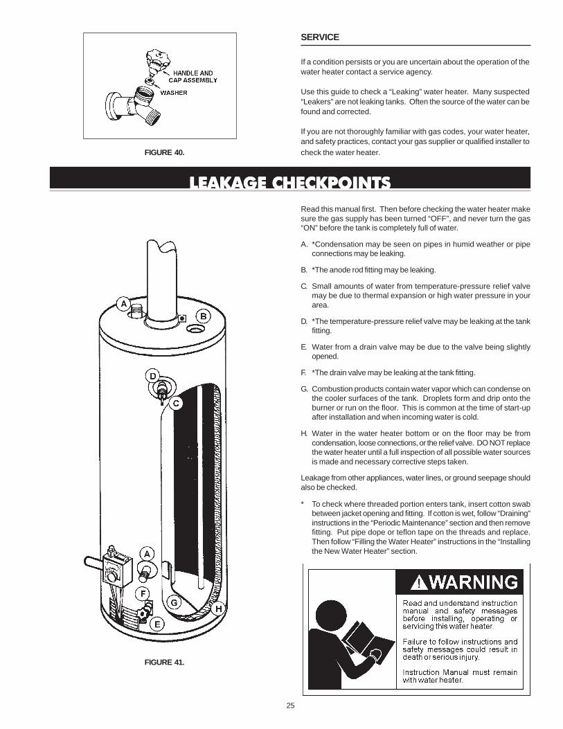
DRAIN VALVE WASHER REPLACEMENT(See Figure 40)
1. Turn “OFF” gas supply to water heater.
2. Follow “Draining” instructions.
3. Turning counterclockwise ( ), remove the hex cap below thescrew handle.
4. Remove the washer and put the new one in place.
5. Screw the handle and cap assembly back into the drain valve andretighten using a wrench. DO NOT OVER TIGHTEN.
6. Follow instructions in the “Filling The Water Heater” section.
7. Check for leaks.
8. Follow the lighting instructions on the “Lighting & Operating Label”section to restart the water heater.
25
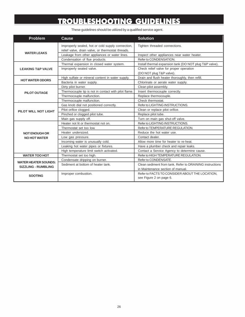
LEAKAGE CHECKPOINTSLEAKAGE CHECKPOINTSLEAKAGE CHECKPOINTSLEAKAGE CHECKPOINTSLEAKAGE CHECKPOINTS
Read this manual first. Then before checking the water heater makesure the gas supply has been turned “OFF”, and never turn the gas“ON” before the tank is completely full of water.
A. *Condensation may be seen on pipes in humid weather or pipeconnections may be leaking.
B. *The anode rod fitting may be leaking.
C. Small amounts of water from temperature-pressure relief valvemay be due to thermal expansion or high water pressure in yourarea.
D. *The temperature-pressure relief valve may be leaking at the tankfitting.
E. Water from a drain valve may be due to the valve being slightlyopened.
F. *The drain valve may be leaking at the tank fitting.
G. Combustion products contain water vapor which can condense onthe cooler surfaces of the tank. Droplets form and drip onto theburner or run on the floor. This is common at the time of start-upafter installation and when incoming water is cold.
H. Water in the water heater bottom or on the floor may be fromcondensation, loose connections, or the relief valve. DO NOT replacethe water heater until a full inspection of all possible water sourcesis made and necessary corrective steps taken.
Leakage from other appliances, water lines, or ground seepage shouldalso be checked.
* To check where threaded portion enters tank, insert cotton swabbetween jacket opening and fitting. If cotton is wet, follow “Draining”instructions in the “Periodic Maintenance” section and then removefitting. Put pipe dope or teflon tape on the threads and replace.Then follow “Filling the Water Heater” instructions in the “Installingthe New Water Heater” section.
FIGURE 40.
SERVICE
If a condition persists or you are uncertain about the operation of thewater heater contact a service agency.
Use this guide to check a “Leaking” water heater. Many suspected“Leakers” are not leaking tanks. Often the source of the water can befound and corrected.
If you are not thoroughly familiar with gas codes, your water heater,and safety practices, contact your gas supplier or qualified installer tocheck the water heater.
FIGURE 41.
26
TROUBLESHOOTING GUIDELINESTROUBLESHOOTING GUIDELINESTROUBLESHOOTING GUIDELINESTROUBLESHOOTING GUIDELINESTROUBLESHOOTING GUIDELINESThese guidelines should be utilized by a qualified service agent.
Problem Cause Solution
Improperly sealed, hot or cold supply connection, Tighten threaded connections.relief valve, drain valve, or thermostat threads.Leakage from other appliances or water lines. Inspect other appliances near water heater.Condensation of flue products. Refer to CONDENSATION.Thermal expansion in closed water system. Install thermal expansion tank (DO NOT plug T&P valve).Improperly seated valve. Check relief valve for proper operation
(DO NOT plug T&P valve).High sulfate or mineral content in water supply. Drain and flush heater thoroughly, then refill.Bacteria in water supply. Chlorinate or aerate water supply.Dirty pilot burner. Clean pilot assembly.Thermocouple tip is not in contact with pilot flame. Insert thermocouple correctly.Thermocouple malfunction. Replace thermocouple.Thermocouple malfunction. Check thermostat.Gas knob dial not positioned correctly. Refer to LIGHTING INSTRUCTIONS.Pilot orifice clogged. Clean or replace pilot orifice.Pinched or clogged pilot tube. Replace pilot tube.Main gas supply off. Turn on main gas shut-off valve.Heater not lit or thermostat not on. Refer to LIGHTING INSTRUCTIONS.Thermostat set too low. Refer to TEMPERATURE REGULATION.Heater undersized. Reduce the hot water use.Low gas pressure. Contact dealer.Incoming water is unusually cold. Allow more time for heater to re-heat.Leaking hot water pipes or fixtures. Have a plumber check and repair leaks.High temperature limit switch activated. Contact a Service Agency to determine cause.Thermostat set too high. Refer to HIGH TEMPERATURE REGULATION.Condensate dripping on burner. Refer to CONDENSATE.Sediment at bottom of heater tank. Clean sediment from tank. Refer to DRAINING instructions
in Maintenance section of manual.Improper combustion. Refer to FACTS TO CONSIDER ABOUT THE LOCATION,
see Figure 2 on page 6.
WATER LEAKS
LEAKING T&P VALVE
HOT WATER ODORS
PILOT OUTAGE
PILOT WILL NOT LIGHT
NOT ENOUGH ORNO HOT WATER
WATER TOO HOT
WATER HEATER SOUNDS:SIZZLING - RUMBLING
SOOTING
27
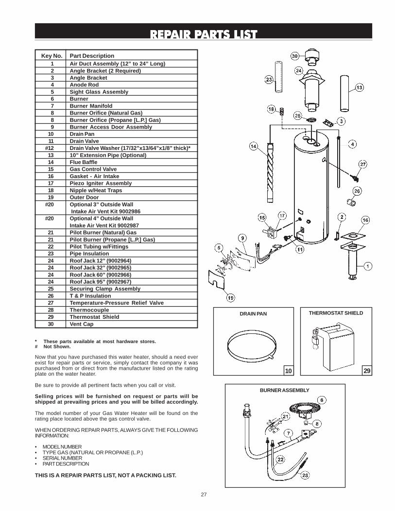
Key No. Part Description 1 Air Duct Assembly (12” to 24” Long)2 Angle Bracket (2 Required)3 Angle Bracket4 Anode Rod5 Sight Glass Assembly6 Burner7 Burner Manifold8 Burner Orifice (Natural Gas)8 Burner Orifice (Propane [L.P.] Gas)9 Burner Access Door Assembly
10 Drain Pan11 Drain Valve
#12 Drain Valve Washer (17/32”x13/64”x1/8” thick)*13 10” Extension Pipe (Optional)14 Flue Baffle15 Gas Control Valve16 Gasket - Air Intake17 Piezo Igniter Assembly18 Nipple w/Heat Traps19 Outer Door
#20 Optional 3” Outside Wall Intake Air Vent Kit 9002986
#20 Optional 4” Outside WallIntake Air Vent Kit 9002987
21 Pilot Burner (Natural) Gas21 Pilot Burner (Propane [L.P.] Gas)22 Pilot Tubing w/Fittings23 Pipe Insulation24 Roof Jack 12” (9002964)24 Roof Jack 32” (9002965)24 Roof Jack 60” (9002966)24 Roof Jack 95” (9002967)25 Securing Clamp Assembly26 T & P Insulation27 Temperature-Pressure Relief Valve28 Thermocouple29 Thermostat Shield30 Vent Cap
* These parts available at most hardware stores.# Not Shown.
Now that you have purchased this water heater, should a need everexist for repair parts or service, simply contact the company it waspurchased from or direct from the manufacturer listed on the ratingplate on the water heater.
Be sure to provide all pertinent facts when you call or visit.
Selling prices will be furnished on request or parts will beshipped at prevailing prices and you will be billed accordingly.
The model number of your Gas Water Heater will be found on therating place located above the gas control valve.
WHEN ORDERING REPAIR PARTS, ALWAYS GIVE THE FOLLOWINGINFORMATION:
• MODEL NUMBER• TYPE GAS (NATURAL OR PROPANE (L.P.)• SERIAL NUMBER• PART DESCRIPTION
THIS IS A REPAIR PARTS LIST, NOT A PACKING LIST.
REPREPREPREPREPAIR PAIR PAIR PAIR PAIR PARTS LISTARTS LISTARTS LISTARTS LISTARTS LIST
BURNER ASSEMBLY
10
DRAIN PAN
29
THERMOSTAT SHIELD

28
Related Documents