Residential and Light Commercial Irrigation Controllers PCC Series Controller 6, 9, 12 & 15 Station Indoor/Outdoor Models Please leave with property owner Pro-C ® Owner’s Manual and Installation Instructions

Welcome message from author
This document is posted to help you gain knowledge. Please leave a comment to let me know what you think about it! Share it to your friends and learn new things together.
Transcript

Residential and Light CommercialIrrigation Controllers
PCC Series Controller6, 9, 12 & 15 StationIndoor/Outdoor Models
Please leave with property owner
Pro-C
®
Owner’s Manual andInstallation Instructions


INTRODUCTION AND INSTALLATIONPro-C Components ....................................................................... 1
Mounting the Indoor Controller to Wall .......................................... 3
Connecting Valves and AC Power .................................................. 4
Connecting the Battery .................................................................. 5
Connecting a Master Valve ............................................................ 5
Connecting a Pump Start Relay ..................................................... 6
Connecting a Weather Sensor ........................................................ 7
Weather Sensor Bypass ................................................................ 7
Connecting an SRR or ICR Remote Control .................................... 8
Connecting to the Hunter ET System ............................................. 9
Connecting to the Hunter Irrigation Management and Monitoring System™ ............................................................ 10
Power Failures ............................................................................ 10
CONTROLLER PROGRAMMING AND OPERATIONSprinkler System Fundamentals .................................................. 11
Creating a Watering Schedule ...................................................... 12
Watering Schedule Form Example ................................................ 13
Programming Fundamentals ........................................................ 14
Table of ConTenTs .............................................................................................................
Programming the Controller ......................................................... 15
Setting the Current Date and Time ............................................ 15
Setting Program Start Times .................................................... 16
Eliminating a Program Start Time ............................................. 16
Setting Station Run Times (Length of Watering for Each Area) .. 16
Setting Days to Water .............................................................. 16
Selecting Specific Days of the Week to Water ............................ 17
Selecting Odd or Even Days to Water ........................................ 17
Selecting Interval Watering ...................................................... 17
Run ......................................................................................... 18
System Off .............................................................................. 18
Manually Run a Single Station .................................................. 18
Seasonal Adjustment ............................................................... 18
One Touch Manual Start and Advance ....................................... 19
Advanced Features ....................................................................... 20
Hidden Features ........................................................................... 21
TROUBLESHOOTING AND SPECIFICATIONSTroubleshooting Guide ................................................................. 24
Specifications .............................................................................. 26
FCC Notice ..................................................................... Back Cover
1
A
C
13
16 15
14
17
18B
B
1
2 3
76
10
9
11
12
4
8
5
13
Pro-C .........................................................................................................................................
2223
25
24
D
21
20
2
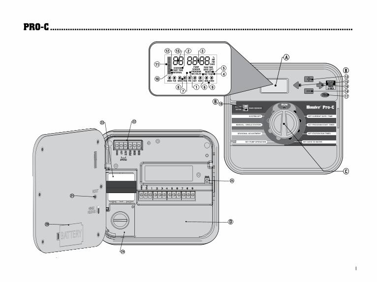
A. – LCD Display1. Program Selector – Identifies the program in use A, B, or C.
2. Station Number – Identifies currently selected station number.
3. Main Display – Indicates various times, values, and programmed information.
4. Year – Identifies current calendar year.
5. Month – Identifies current calendar month.
6. Day – Identifies current calendar day.
7. Running – Sprinkler icon indicates when watering is occurring.
8. Days of the week – Identifies days of the week to water or not water.
9. Odd/Even Watering – Identifies if odd or even watering is selected.
10. Interval – Identifies if interval watering has been selected.
11. Seasonal Adjust – Displays in increments of 5%, the percentage of seasonal adjust that has been selected.
12. Start Time – Identifies selected program start time.
B. – Control Buttons and Switches13. Button – Increases the selected flashing display.
14. Button – Decreases the selected flashing display.
15. Button – Returns selected flashing display to the previous item.
16. Button – Advances the selected flashing display to the next item. Also to start a manual cycle.
17. Button – Selects programs A, B, and C. Also to start a test program.
18. Rain Sensor Bypass Switch – Use to bypass weather sensor, if one is installed.
C. – Control DialRun – Normal dial position for automatic operation.
Set Current Date/Time – Set current date time.
Set Program Start Times – Set 1 to 4 start times in each program.
Set Station Run Times – Set each station run time.
Set Days to Water – Select individual days to water, odd, even, or interval watering schedule.
Set Pump Operation – Turn pump or master valve on or off for each station.
Manual – Single Station – Activates a one time watering of a single station.
Seasonal Adjustment – Make global run time changes without repro-gramming the controller (from 5% to 300%).
System Off – Used to discontinue all programs and stop all watering until the dial is returned to the RUN position, or to set the program-mable rain off feature.
D. – Wiring Compartment20. 9-Volt Battery – An alkaline battery (not included) allows you to
program the controller without AC power.
21. Reset Button – This button will reset the controller. All programmed data will remain intact.
22. Power Area – Used to attach transformer, sensor wires, and other systems to the controller.
23. Transformer – A transformer is installed (Outdoor models only, indoor models are supplied with a plug-in transformer.)
24. Junction Box – This box provides an area for connecting primary AC power. (Outdoor models only.)
25. Ground Lug.
3
MoUnTInG THe ConTroller To a Wall .......................................................................
C
A
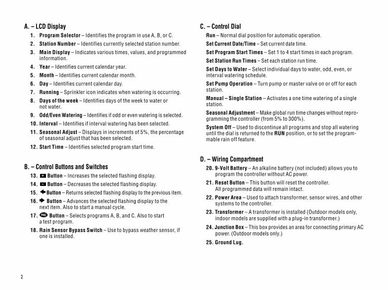
BAll necessary hardware is included for most installations.
NOTE: The indoor Pro-C is not weather or water resistant, and must be installed indoors or in a protected area. This device is not intended for use by young children. Never let children play with this device.
1. Select a location close to an electrical outlet or power supply that is not controlled by a light switch.
2. Remove the front panel from the Pro-C by first removing the ribbon connector and then pulling down the hinge release. Removing the front panel will ease installation of the controller cabinet.
3. Use the hole at the top of the controller as a reference and secure one 25mm screw (A) into the wall. Note: Install screw anchors if attaching to drywall or masonry wall.
4. Align controller with the screw and slide the keyhole (B) on top of the controller over the screw.
5. Secure controller in place by installing screws in the holes (C).
NOTE: Outdoor model is water and weather resistant. Connecting the outdoor Pro-C to the primary power should be done by a licensed electrician following all local codes. Improper installation could result in shock or fire hazard. This device is not intended for use by young children. Never let children play with this device.
For PC-301-A:If the supply cord is damaged, it must be replaced by the manufacturer or service agent or a similarly qualified person in order to avoid hazard.
4
ConneCTInG ValVes and aC PoWer ..............................................................................
Transformer
Valve 1
Valve 2
Valve 3
Valve 4
alve Common Wire
alveWires
V
V
YellowYellowGreen
AC2AC1GND
3 Wires
Connect the Two YellowTransformer Wires tothe Two AC Terminalsand the Green Wire tothe GND Terminal
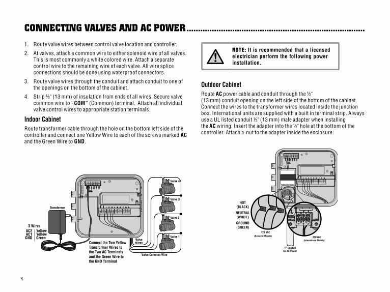
1. Route valve wires between control valve location and controller.
2. At valves, attach a common wire to either solenoid wire of all valves. This is most commonly a white colored wire. Attach a separate control wire to the remaining wire of each valve. All wire splice connections should be done using waterproof connectors.
3. Route valve wires through the conduit and attach conduit to one of the openings on the bottom of the cabinet.
4. Strip ½" (13 mm) of insulation from ends of all wires. Secure valve common wire to “COM” (Common) terminal. Attach all individual valve control wires to appropriate station terminals.
Indoor CabinetRoute transformer cable through the hole on the bottom left side of the controller and connect one Yellow Wire to each of the screws marked AC and the Green Wire to GND.
NOTE: It is recommended that a licensed electrician perform the following power installation.
Outdoor CabinetRoute AC power cable and conduit through the ½" (13 mm) conduit opening on the left side of the bottom of the cabinet. Connect the wires to the transformer wires located inside the junction box. International units are supplied with a built in terminal strip. Always use a UL listed conduit ½" (13 mm) male adapter when installing the AC wiring. Insert the adapter into the ½" hole at the bottom of the controller. Attach a nut to the adapter inside the enclosure.
½" Conduitfor AC Power
230 VAC(International Models)
120 VAC(Domestic Models)
HOT(BLACK)
NEUTRAL(WHITE)
GROUND(GREEN)
5
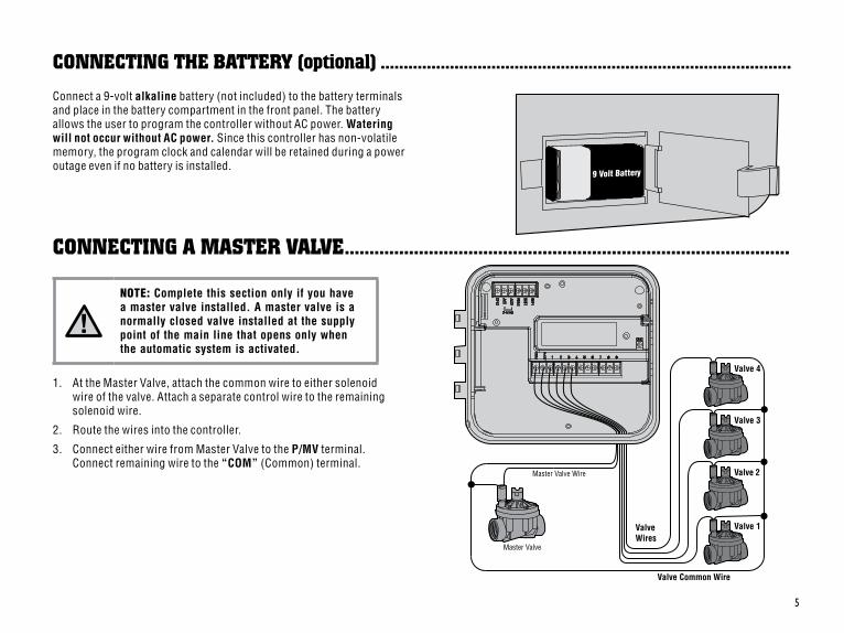
Connect a 9-volt alkaline battery (not included) to the battery terminals and place in the battery compartment in the front panel. The battery allows the user to program the controller without AC power. Watering will not occur without AC power. Since this controller has non-volatile memory, the program clock and calendar will be retained during a power outage even if no battery is installed.
9 Volt Battery
Valve 1
Valve 2
Valve 3
Valve 4
Valve Common Wire
ValveWires
Master Valve
Master Valve Wire
ConneCTInG THe baTTerY (optional) .........................................................................................
ConneCTInG a MasTer ValVe ..........................................................................................
NOTE: Complete this section only if you have a master valve installed. A master valve is a normally closed valve installed at the supply point of the main line that opens only when the automatic system is activated.
1. At the Master Valve, attach the common wire to either solenoid wire of the valve. Attach a separate control wire to the remaining solenoid wire.
2. Route the wires into the controller.
3. Connect either wire from Master Valve to the P/MV terminal. Connect remaining wire to the “COM” (Common) terminal.
6
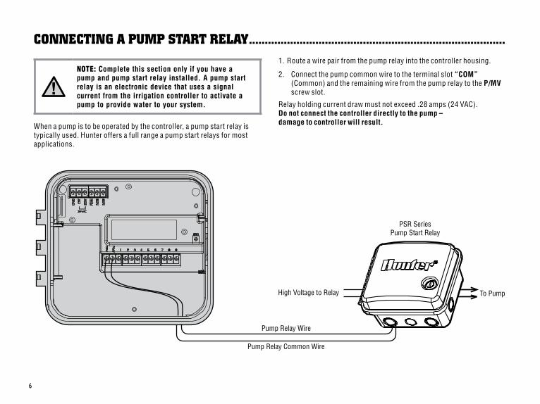
1. Route a wire pair from the pump relay into the controller housing.
2. Connect the pump common wire to the terminal slot “COM” (Common) and the remaining wire from the pump relay to the P/MV screw slot.
Relay holding current draw must not exceed .28 amps (24 VAC). Do not connect the controller directly to the pump – damage to controller will result.
High Voltage to Relay To Pump
Pump Relay Common Wire
PSR SeriesPump Start Relay
Pump Relay Wire
NOTE: Complete this section only if you have a pump and pump start relay installed. A pump start relay is an electronic device that uses a signal current from the irrigation controller to activate a pump to provide water to your system.
When a pump is to be operated by the controller, a pump start relay is typically used. Hunter offers a full range a pump start relays for most applications.
ConneCTInG a PUMP sTarT relaY .................................................................................
7
Sensor Wire to SEN
Mini-Clik ®
Weather Sensor
Sensor Wire to SEN
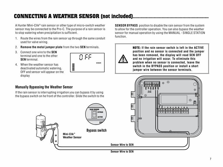
A Hunter Mini-Clik® rain sensor or other type of micro-switch weather sensor may be connected to the Pro-C. The purpose of a rain sensor is to stop watering when precipitation is sufficient.
1. Route the wires from the rain sensor up through the same conduit used for valve wiring.
2. Remove the metal jumper plate from the two SEN terminals.
3. Connect one wire to the SEN terminal and one to the other SEN terminal.
4. When the weather sensor has deactivated automatic watering, OFF and sensor will appear on the display
Manually Bypassing the Weather SensorIf the rain sensor is interrupting irrigation you can bypass it by using the bypass switch on he front of the controller. Slide the switch to the
RAIN SENSORBYPASS
ACTIVE
SYSTEM
SENSOR
ConneCTInG a WeaTHer sensor (not included) ..........................................................
NOTE: If the rain sensor switch is left in the ACTIVE position and no sensor is connected and the jumper has been removed, the display will read SEN OFF and no irrigation will occur. To eliminate this problem when no sensor is connected, leave the switch in the BYPASS position or install a short jumper wire between the sensor terminals.
Bypass switch
SENSOR BYPASS position to disable the rain sensor from the system to allow for the controller operation. You can also bypass the weather sensor for manual operation by using the MANUAL - SINGLE STATION function.
8
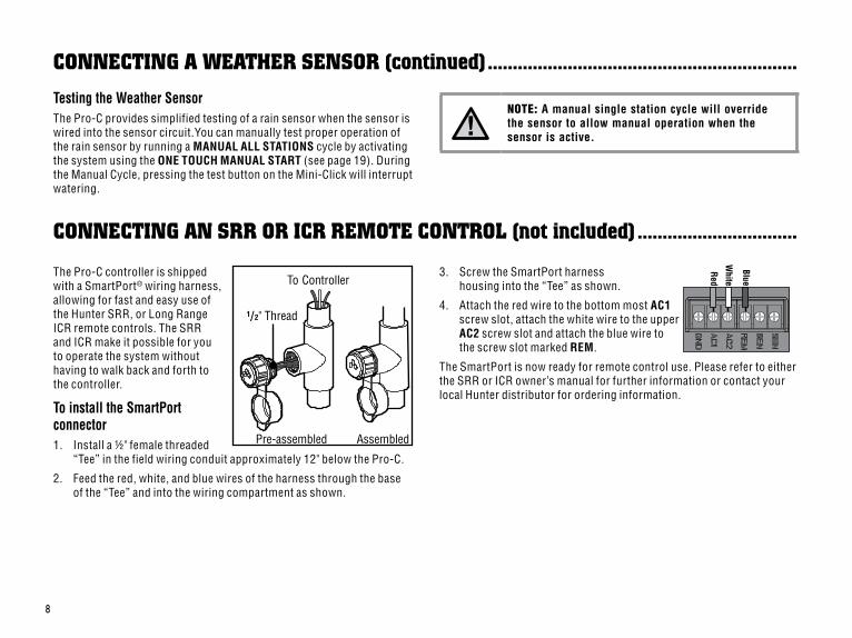
ConneCTInG an srr or ICr reMoTe ConTrol (not included) ................................
1/2" Thread
To Controller
Pre-assembled Assembled
The Pro-C controller is shipped with a SmartPort® wiring harness, allowing for fast and easy use of the Hunter SRR, or Long Range ICR remote controls. The SRR and ICR make it possible for you to operate the system without having to walk back and forth to the controller.
To install the SmartPort connector1. Install a ½" female threaded
“Tee” in the field wiring conduit approximately 12" below the Pro-C.
2. Feed the red, white, and blue wires of the harness through the base of the “Tee” and into the wiring compartment as shown.
3. Screw the SmartPort harness housing into the “Tee” as shown.
4. Attach the red wire to the bottom most AC1 screw slot, attach the white wire to the upper AC2 screw slot and attach the blue wire to the screw slot marked REM.
The SmartPort is now ready for remote control use. Please refer to either the SRR or ICR owner’s manual for further information or contact your local Hunter distributor for ordering information.
Testing the Weather SensorThe Pro-C provides simplified testing of a rain sensor when the sensor is wired into the sensor circuit.You can manually test proper operation of the rain sensor by running a MANUAL ALL STATIONS cycle by activating the system using the ONE TOUCH MANUAL START (see page 19). During the Manual Cycle, pressing the test button on the Mini-Click will interrupt watering.
ConneCTInG a WeaTHer sensor (continued) ..............................................................
Red
Blue
White
NOTE: A manual single station cycle will override the sensor to allow manual operation when the sensor is active.
9
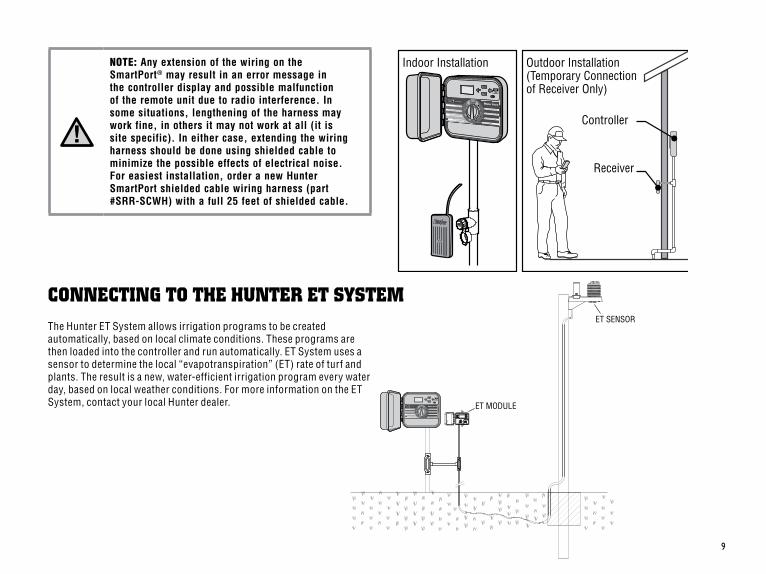
NOTE: Any extension of the wiring on the SmartPort® may result in an error message in the controller display and possible malfunction of the remote unit due to radio interference. In some situations, lengthening of the harness may work fine, in others it may not work at all (it is site specific). In either case, extending the wiring harness should be done using shielded cable to minimize the possible effects of electrical noise. For easiest installation, order a new Hunter SmartPort shielded cable wiring harness (part #SRR-SCWH) with a full 25 feet of shielded cable.
Controller
Receiver
Outdoor Installation(Temporary Connection of Receiver Only)
Indoor Installation
ConneCTInG To THe HUnTer eT sYsTeMThe Hunter ET System allows irrigation programs to be created automatically, based on local climate conditions. These programs are then loaded into the controller and run automatically. ET System uses a sensor to determine the local “evapotranspiration” (ET) rate of turf and plants. The result is a new, water-efficient irrigation program every water day, based on local weather conditions. For more information on the ET System, contact your local Hunter dealer. ET MODULE
ET SENSOR
10
PoWer faIlUres ...................................................................................................................
With the Irrigation Management and Monitoring System™ (IMMS™), automatic irrigation systems at multiple sites or multiple controllers on a single site can be programmed for functions that would typically be handled directly at each site’s controller. Scheduling of days to water, run times, start times, cycle and soak operations, and more can now be done from a single computer at a desk miles away from the actual installation.
In addition, scheduled operation of non-irrigation components also in use at these sites – e.g., lighting systems at athletic fields, fountains at shopping centers – as well as pumps and sensors can also be programmed and monitored from a single central location.
A key function of the IMMS is its ability to monitor changing conditions. With the aid of such options as flow sensors, rain sensors, and other weather-sensing devices, the IMMS can receive reports on the current condition at every site it is linked with and then respond with the necessary adjustments should any of those conditions go beyond the limits that have been defined.
ConneCTInG To THe HUnTer IrrIGaTIon ManaGeMenT and MonITorInG sYsTeM™ ..................................................................
No system available today is more cost-effective than the Hunter IMMS. It’s inexpensively priced and contains the most essential features needed for water management. It’s able to team with any or all of the standard automatic controllers in the Hunter line-up, from the SRC to the Pro-C to the ICC. Plus, it’s a system that’s easy and affordable to upgrade, making it possible to accommodate an expanding network of controllers.
For more information on the IMMS, contact your local Hunter dealer.
Due to the possibility of power failures, the controller has non-volatile memory to preserve the program indefinitely. There is no default program.
The Pro-C is also capable of keeping the current time and date for an extended period of time during power outage conditions.
11
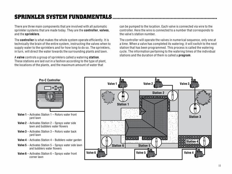
sPrInKler sYsTeM fUndaMenTals .............................................................................There are three main components that are involved with all automatic sprinkler systems that are made today. They are the controller, valves, and the sprinklers.
The controller is what makes the whole system operate efficiently. It is technically the brain of the entire system, instructing the valves when to supply water to the sprinklers and for how long to do so. The sprinklers, in turn, will direct the water towards the surrounding plants and lawn.
A valve controls a group of sprinklers called a watering station. These stations are laid out in a fashion according to the type of plant, the locations of the plants, and the maximum amount of water that
can be pumped to the location. Each valve is connected via wire to the controller. Here the wire is connected to a number that corresponds to the valve’s station number.
The controller will operate the valves in numerical sequence, only one at a time. When a valve has completed its watering; it will switch to the next station that has been programmed. This process is called the watering cycle. The information pertaining to the watering times of the individual stations and the duration of them is called a program.
V alve 1 – Activates Station 1 – Rotors water front yard lawn
V alve 2 – Activates Station 2 – Sprays water side lawn and bubblers water flowers
V alve 3 – Activates Station 3 – Rotors water back yard lawn
V alve 4 – Activates Station 4 – Bubblers water garden
V alve 5 – Activates Station 5 – Sprays water side lawn and bubblers water flowers
V alve 6 – Activates Station 6 – Sprays water front corner lawn
Va lve 1
Station 1
Station 2
Station 3
Station 6
Va lve 2 V alve 3
Va lve 5
Pro-C Controller
Station 5
Va lve 4 V alve 6
Station 4
12
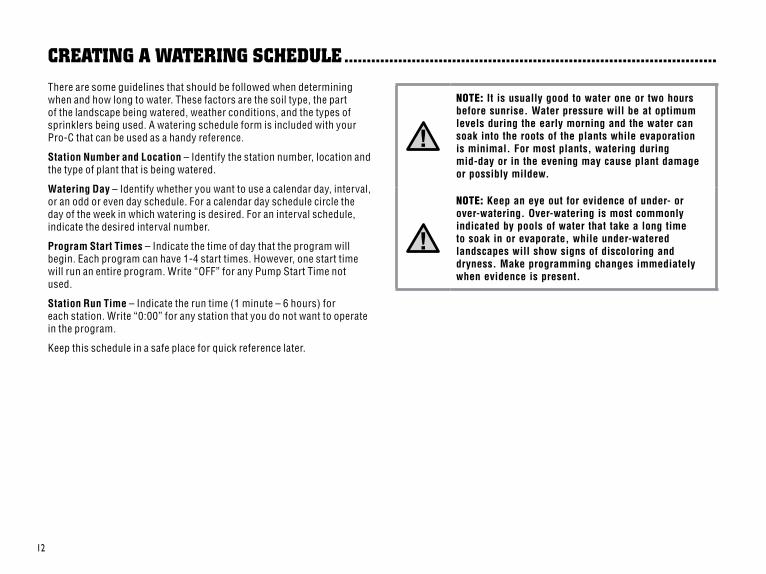
CreaTInG a WaTerInG sCHedUle ...................................................................................There are some guidelines that should be followed when determining when and how long to water. These factors are the soil type, the part of the landscape being watered, weather conditions, and the types of sprinklers being used. A watering schedule form is included with your Pro-C that can be used as a handy reference.
Station Number and Location – Identify the station number, location and the type of plant that is being watered.
Watering Day – Identify whether you want to use a calendar day, interval, or an odd or even day schedule. For a calendar day schedule circle the day of the week in which watering is desired. For an interval schedule, indicate the desired interval number.
Program Start Times – Indicate the time of day that the program will begin. Each program can have 1-4 start times. However, one start time will run an entire program. Write “OFF” for any Pump Start Time not used.
Station Run Time – Indicate the run time (1 minute – 6 hours) for each station. Write “0:00” for any station that you do not want to operate in the program.
Keep this schedule in a safe place for quick reference later.
NOTE: It is usually good to water one or two hours before sunrise. Water pressure will be at optimum levels during the early morning and the water can soak into the roots of the plants while evaporation is minimal. For most plants, watering during mid-day or in the evening may cause plant damage or possibly mildew.
NOTE: Keep an eye out for evidence of under- or over-watering. Over-watering is most commonly indicated by pools of water that take a long time to soak in or evaporate, while under-watered landscapes will show signs of discoloring and dryness. Make programming changes immediately when evidence is present.
13
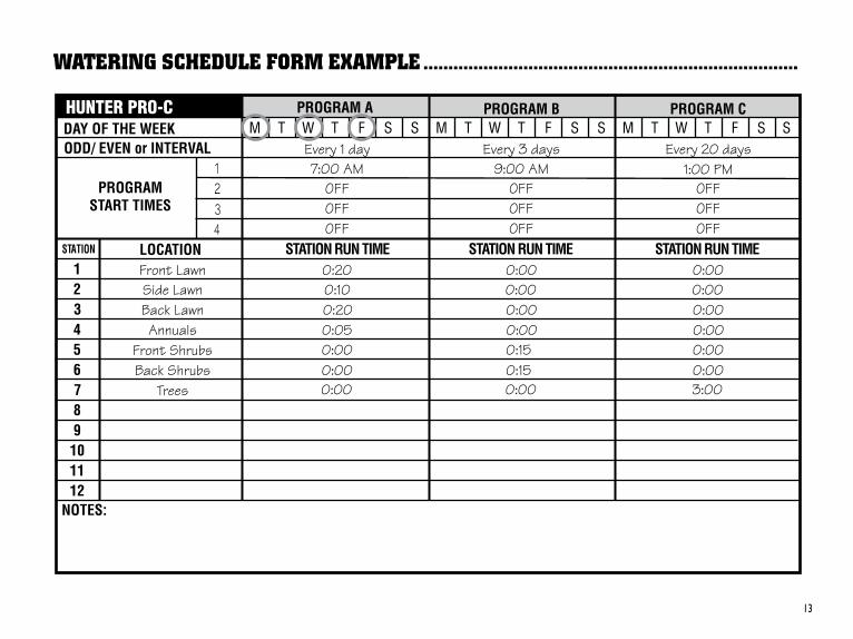
WaTerInG sCHedUle forM exaMPle ...........................................................................
14
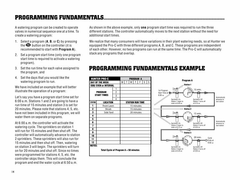
ProGraMMInG fUndaMenTals......................................................................................A watering program can be created to operate valves in numerical sequence one at a time. To create a watering program:
1. Select a program (A, B, or C) by pressing the button on the controller (it is recommended to start with Program A).
2. Set a program start time (only one program start time is required to activate a watering program).
3. Set the run time for each valve assigned to the program, and
4. Set the days that you would like the watering program to run.
We have included an example that will better illustrate the operation of a program:
Let’s say you have a program start time set for 6:00 a.m. Stations 1 and 2 are going to have a run time of 15 minutes and station 3 is set for 20 minutes. Please note that stations 4, 5, etc. have not been included in this program, we will water them on separate programs.
At 6:00 a.m. the controller will activate the watering cycle. The sprinklers on station 1 will run for 15 minutes and then shut off. The controller will automatically advance to station 2 sprinklers. These sprinklers will also run for 15 minutes and then shut off. Then, watering on station 3 will begin. The sprinklers will turn on for 20 minutes and shut off. Since no times were programmed for stations 4, 5, etc. the controller skips them. This will conclude the program and end the water cycle at 6:50 a.m.
As shown in the above example, only one program start time was required to run the three different stations. The controller automatically moves to the next station without the need for additional start times.
We realize that many consumers will have variations in their plant watering needs, so at Hunter we equipped the Pro-C with three different programs A, B, and C. These programs are independent of each other. However, no two programs can run at the same time. The Pro-C will automatically stack any programs that overlap.
ProGraMMInG fUndaMenTals exaMPle
15
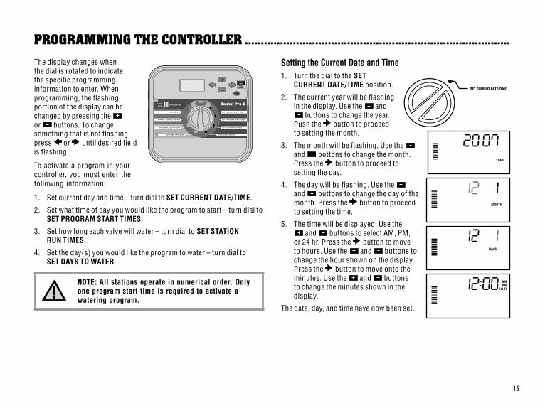
The display changes when the dial is rotated to indicate the specific programming information to enter. When programming, the flashing portion of the display can be changed by pressing the or buttons. To change something that is not flashing, press or until desired field is flashing.
To activate a program in your controller, you must enter the following information:
1. Set current day and time – turn dial to SET CURRENT DATE/TIME.
2. Set what time of day you would like the program to start – turn dial to SET PROGRAM START TIMES.
3. Set how long each valve will water – turn dial to SET STATION RUN TIMES.
4. Set the day(s) you would like the program to water – turn dial to SET DAYS TO WATER.
NOTE: All stations operate in numerical order. Only one program start time is required to activate a watering program.
Setting the Current Date and Time1. Turn the dial to the SET
CURRENT DATE/TIME position.
2. The current year will be flashing in the display. Use the and
buttons to change the year. Push the button to proceed to setting the month.
3. The month will be flashing. Use the and buttons to change the month. Press the button to proceed to setting the day.
4. The day will be flashing. Use the and buttons to change the day of the month. Press the button to proceed to setting the time.
5. The time will be displayed: Use the and buttons to select AM, PM,
or 24 hr. Press the button to move to hours. Use the and buttons to change the hour shown on the display. Press the button to move onto the minutes. Use the and buttons to change the minutes shown in the display.
The date, day, and time have now been set.
ProGraMMInG THe ConTroller ...................................................................................Residential and Light CommercialIrrigation Controllers
PCC Series Controller
Owner’s Manual andInstallation Instructions
Please leave with property owner
Pro-C
®
SET CURRENT DATE/TIME
16
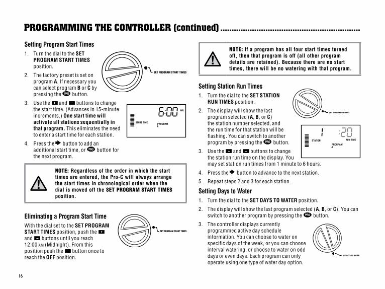
NOTE: If a program has all four start times turned off, then that program is off (all other program details are retained). Because there are no start times, there will be no watering with that program.
Setting Station Run Times1. Turn the dial to the SET STATION
RUN TIMES position.
2. The display will show the last program selected (A, B, or C) the station number selected, and the run time for that station will be flashing. You can switch to another program by pressing the button.
3. Use the and buttons to change the station run time on the display. You may set station run times from 1 minute to 6 hours.
4. Press the button to advance to the next station.
5. Repeat steps 2 and 3 for each station.
Setting Days to Water1. Turn the dial to the SET DAYS TO WATER position.
2. The display will show the last program selected (A, B, or C). You can switch to another program by pressing the button.
3. The controller displays currently programmed active day schedule information. You can choose to water on specific days of the week, or you can choose interval watering, or choose to water on odd days or even days. Each program can only operate using one type of water day option.
Setting Program Start Times1. Turn the dial to the SET
PROGRAM START TIMES position.
2. The factory preset is set on program A. If necessary you can select program B or C by pressing the button.
3. Use the and buttons to change the start time. (Advances in 15-minute increments.) One start time will activate all stations sequentially in that program. This eliminates the need to enter a start time for each station.
4. Press the button to add an additional start time, or button for the next program.
NOTE: Regardless of the order in which the start times are entered, the Pro-C will always arrange the start times in chronological order when the dial is moved off the SET PROGRAM START TIMES position.
Eliminating a Program Start TimeWith the dial set to the SET PROGRAM START TIMES position, push the and buttons until you reach 12:00 am (Midnight). From this position push the button once to reach the OFF position.
ProGraMMInG THe ConTroller (continued) ..............................................................
SET DAYS TO WATER
SET PROGRAM START TIMES
SET PROGRAM START TIMES
SET STATION RUN TIMES
17
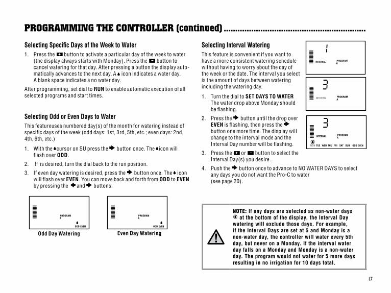
Selecting Specific Days of the Week to Water1. Press the button to activate a particular day of the week to water
(the display always starts with Monday). Press the button to cancel watering for that day. After pressing a button the display auto-matically advances to the next day. A icon indicates a water day. A blank space indicates a no water day.
After programming, set dial to RUN to enable automatic execution of all selected programs and start times.
Selecting Odd or Even Days to WaterThis featureuses numbered day(s) of the month for watering instead of specific days of the week (odd days: 1st, 3rd, 5th, etc.; even days: 2nd, 4th, 6th, etc.)
1. With the cursor on SU press the button once. The icon will flash over ODD.
2. If is desired, turn the dial back to the run position.
3. If even day watering is desired, press the button once. The icon will flash over EVEN. You can move back and forth from ODD to EVEN by pressing the and buttons.
Selecting Interval WateringThis feature is convenient if you want to have a more consistent watering schedule without having to worry about the day of the week or the date. The interval you select is the amount of days between watering including the watering day.
1. Turn the dial to SET DAYS TO WATERThe water drop above Monday should be flashing.
2. Press the button until the drop over EVEN is flashing, then press the button one more time. The display will change to the interval mode and the Interval Day number will be flashing.
3. Press the or button to select the Interval Day(s) you desire.
4. Push the button once to advance to NO WATER DAYS to select any days you do not want the Pro-C to water (see page 20).
NOTE: If any days are selected as non-water days at the bottom of the display, the Interval Day
watering will exclude those days. For example, if the Interval Days are set at 5 and Monday is a non-water day, the controller will water every 5th day, but never on a Monday. If the interval water day falls on a Monday and Monday is a non-water day. The program would not water for 5 more days resulting in no irrigation for 10 days total.
ProGraMMInG THe ConTroller (continued) ..............................................................
Odd Day Watering Even Day Watering
18
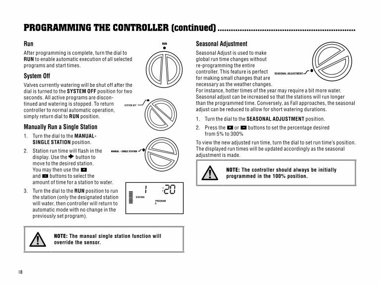
RunAfter programming is complete, turn the dial to RUN to enable automatic execution of all selected programs and start times.
System OffValves currently watering will be shut off after the dial is turned to the SYSTEM OFF position for two seconds. All active programs are discon-tinued and watering is stopped. To return controller to normal automatic operation, simply return dial to RUN position.
Manually Run a Single Station1. Turn the dial to the MANUAL-
SINGLE STATION position.
2. Station run time will flash in the display. Use the button to move to the desired station. You may then use the and buttons to select the amount of time for a station to water.
3. Turn the dial to the RUN position to run the station (only the designated station will water, then controller will return to automatic mode with no change in the previously set program).
NOTE: The manual single station function will override the sensor.
Seasonal AdjustmentSeasonal Adjust is used to make global run time changes without re-programming the entire controller. This feature is perfect for making small changes that are necessary as the weather changes. For instance, hotter times of the year may require a bit more water. Seasonal adjust can be increased so that the stations will run longer than the programmed time. Conversely, as Fall approaches, the seasonal adjust can be reduced to allow for short watering durations.
1. Turn the dial to the SEASONAL ADJUSTMENT position.
2. Press the or buttons to set the percentage desiredfrom 5% to 300%
To view the new adjusted run time, turn the dial to set run time’s position. The displayed run times will be updated accordingly as the seasonal adjustment is made.
NOTE: The controller should always be initially programmed in the 100% position.
ProGraMMInG THe ConTroller (continued) ..............................................................
SYSTEM OFF
RUN
SEASONAL ADJUSTMENT
MANUAL – SINGLE STATION
19
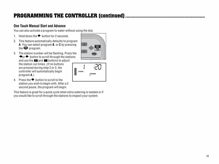
One Touch Manual Start and AdvanceYou can also activate a program to water without using the dial.
1. Hold down the button for 2 seconds.
2. This feature automatically defaults to program A. You can select program B, or C by pressing the program.
3. The station number will be flashing. Press theor button to scroll through the stations
and use the and buttons to adjust the station run times. (If no buttons are pressed during step 2 or 3, the controller will automatically begin program A.)
4. Press the button to scroll to the station you wish to begin with. After a 2 second pause, the program will begin.
This feature is great for a quick cycle when extra watering is needed or if you would like to scroll through the stations to inspect your system.
ProGraMMInG THe ConTroller (continued) ..............................................................
Pro-C®
RUNRAIN SENSORBYPASS
ACTIVE
SET CURRENT DATE / TIME
SET PROGRAM START TIMES
SET DAYS TO WATER
SET STATION RUN TIMES
SYSTEM OFF
MANUAL – ALL STATIONS
SET PUMP OPERATION
MANUAL – SINGLE STATION
20
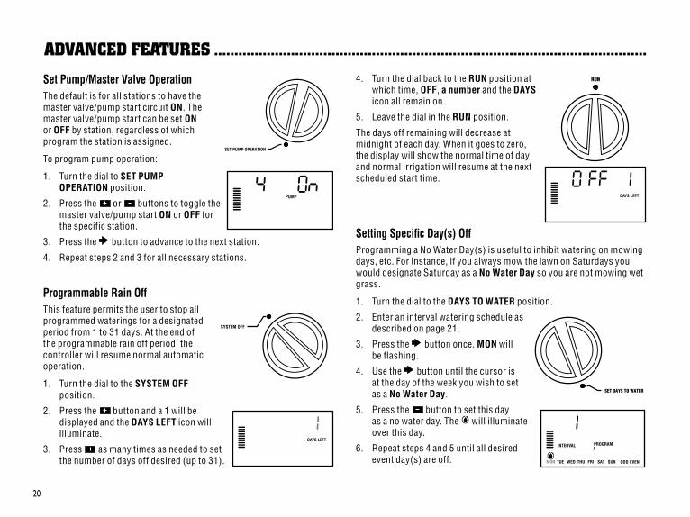
Set Pump/Master Valve OperationThe default is for all stations to have the master valve/pump start circuit ON. The master valve/pump start can be set ON or OFF by station, regardless of which program the station is assigned.
To program pump operation:
1. Turn the dial to SET PUMP OPERATION position.
2. Press the or buttons to toggle the master valve/pump start ON or OFF for the specific station.
3. Press the button to advance to the next station.
4. Repeat steps 2 and 3 for all necessary stations.
Programmable Rain OffThis feature permits the user to stop all programmed waterings for a designated period from 1 to 31 days. At the end of the programmable rain off period, the controller will resume normal automatic operation.
1. Turn the dial to the SYSTEM OFF position.
2. Press the button and a 1 will be displayed and the DAYS LEFT icon will illuminate.
3. Press as many times as needed to set the number of days off desired (up to 31).
4. Turn the dial back to the RUN position at which time, OFF, a number and the DAYS icon all remain on.
5. Leave the dial in the RUN position.
The days off remaining will decrease at midnight of each day. When it goes to zero, the display will show the normal time of day and normal irrigation will resume at the next scheduled start time.
Setting Specific Day(s) OffProgramming a No Water Day(s) is useful to inhibit watering on mowing days, etc. For instance, if you always mow the lawn on Saturdays you would designate Saturday as a No Water Day so you are not mowing wet grass.
1. Turn the dial to the DAYS TO WATER position.
2. Enter an interval watering schedule as described on page 21.
3. Press the button once. MON will be flashing.
4. Use the button until the cursor is at the day of the week you wish to set as a No Water Day.
5. Press the button to set this day as a no water day. The will illuminate over this day.
6. Repeat steps 4 and 5 until all desired event day(s) are off.
adVanCed feaTUres ...........................................................................................................
SET PUMP OPERATION
SYSTEM OFF
RUN
SET DAYS TO WATER
21
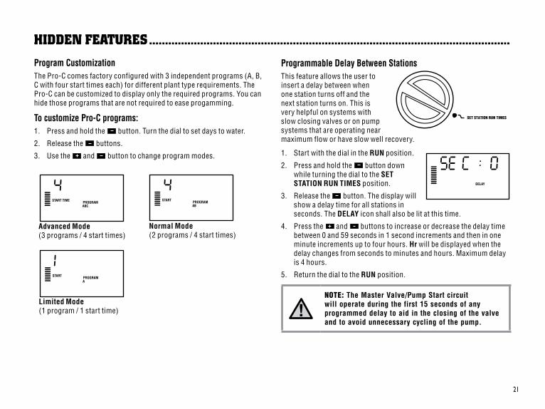
Program CustomizationThe Pro-C comes factory configured with 3 independent programs (A, B, C with four start times each) for different plant type requirements. The Pro-C can be customized to display only the required programs. You can hide those programs that are not required to ease progamming.
To customize Pro-C programs:1. Press and hold the button. Turn the dial to set days to water.
2. Release the buttons.
3. Use the and button to change program modes.
Programmable Delay Between StationsThis feature allows the user to insert a delay between when one station turns off and the next station turns on. This is very helpful on systems with slow closing valves or on pump systems that are operating near maximum flow or have slow well recovery.
1. Start with the dial in the RUN position.
2. Press and hold the button down while turning the dial to the SET STATION RUN TIMES position.
3. Release the button. The display will show a delay time for all stations in seconds. The DELAY icon shall also be lit at this time.
4. Press the and buttons to increase or decrease the delay time between 0 and 59 seconds in 1 second increments and then in one minute increments up to four hours. Hr will be displayed when the delay changes from seconds to minutes and hours. Maximum delay is 4 hours.
5. Return the dial to the RUN position.
NOTE: The Master Valve/Pump Start circuit will operate during the first 15 seconds of any programmed delay to aid in the closing of the valve and to avoid unnecessary cycling of the pump.
HIdden feaTUres .................................................................................................................
Advanced Mode(3 programs / 4 start times)
Normal Mode(2 programs / 4 start times)
Limited Mode(1 program / 1 start time)
SET STATION RUN TIMES
22
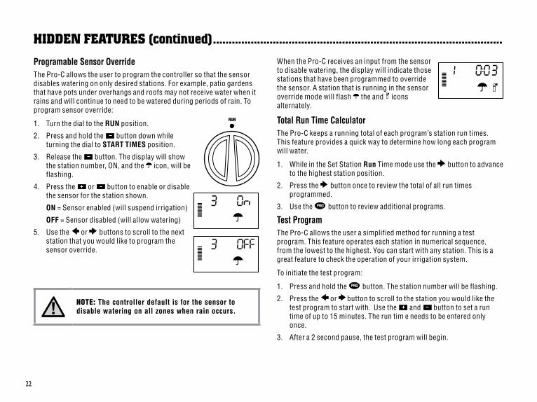
Programable Sensor OverrideThe Pro-C allows the user to program the controller so that the sensor disables watering on only desired stations. For example, patio gardens that have pots under overhangs and roofs may not receive water when it rains and will continue to need to be watered during periods of rain. To program sensor override:
1. Turn the dial to the RUN position.
2. Press and hold the button down while turning the dial to START TIMES position.
3. Release the button. The display will show the station number, ON, and the icon, will be flashing.
4. Press the or button to enable or disable the sensor for the station shown.
ON = Sensor enabled (will suspend irrigation)
OFF = Sensor disabled (will allow watering)
5. Use the or buttons to scroll to the next station that you would like to program the sensor override.
NOTE: The controller default is for the sensor to disable watering on all zones when rain occurs.
When the Pro-C receives an input from the sensor to disable watering, the display will indicate those stations that have been programmed to override the sensor. A station that is running in the sensor override mode will flash the and icons alternately.
Total Run Time CalculatorThe Pro-C keeps a running total of each program’s station run times. This feature provides a quick way to determine how long each program will water.
1. While in the Set Station Run Time mode use the button to advance to the highest station position.
2. Press the button once to review the total of all run times programmed.
3. Use the button to review additional programs.
Test ProgramThe Pro-C allows the user a simplified method for running a test program. This feature operates each station in numerical sequence, from the lowest to the highest. You can start with any station. This is a great feature to check the operation of your irrigation system.
To initiate the test program:
1. Press and hold the button. The station number will be flashing.
2. Press the or button to scroll to the station you would like the test program to start with. Use the and button to set a run time of up to 15 minutes. The run tim e needs to be entered only once.
3. After a 2 second pause, the test program will begin.
RUN
HIdden feaTUres (continued) ............................................................................................
23
Easy Retrive™ Program MemoryThe Pro-C is capable of saving the preferred watering program into memory for retrieval at a later time. This feature allows for a quick way of resetting the controller to the original programmed watering schedule.
To save the program into memory.
1. With the dial in the RUN postiion, press and hold the and buttons for 5 seconds. The display will scroll from left to right across the display indicating the program is being saved into memory.
2. Release the and buttons.
To retrieve a program that was previously saved into memory.
1. With the dial in the RUN position, press and hold the and buttons for 5 seconds. The display will scroll from right to left across the display indicating the program is being saved into memory.
2. Release the and buttons
Hunter Quick Check™
This circuit diagnostic procedure is can quickly identify “shorts” commonly caused by faulty solenoids or when a bare common wire touches a bare station control wire.
To initiate the Hunter Quick Check test procedure:
1. Press the , , and buttons simultaneously. In the standby mode, the LCD will display all segments (helpful when troubleshoot-ing display problems).
2. Press the button to begin the Quick Check test procedure. The system will search all stations to detect a high current path through the station terminals. When a field wiring short is detected, an ERR symbol preceded by the station number will momentarily flash on the controller LCD display. After the Hunter Quick Check completes running this circuit diagnostic procedure, the controller returns to the automatic watering mode.
Clearing Controller’s Memory/Resetting ControllerIf you feel that you have misprogrammed the controller, there is a process that will reset the memory to factory defaults and erase all programs and data that have been entered into the controller. Press and hold the button. Press and release the RESET button on the back of the front panel. Wait until the display shows 12:00am. Release the button. All the memory has been cleared and the controller may now be reprogrammed.
WINTERIZING YOUR SYSTEMIn regions within the country where the frost level falls below the depth of the installed piping, it is common for these systems to be “winterized”. Several methods can be used to drain the water from the system. If the blow out method is used it is recommended that a qualified licensed contract perform this type of winterization.
WARNING! WEAR ANSI APPROVED SAFETY EYE PROTECTION! Extreme care must always be taken when blowing out the system with compressed air. Compressed air can cause serious injury, including serious eye injury from flying debris. Always wear ANSI approved safety eye protection and do not stand over any irrigation components (pipes, sprinklers, and valves) during blow out. SERIOUS PERSONAL INJURY MAY RESULT IF YOU DO NOT PROCEED AS RECOMMENDED.
HIdden feaTUres (continued) ............................................................................................
24
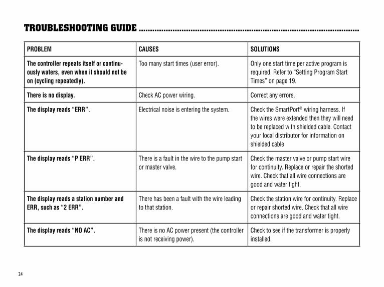
TroUblesHooTInG GUIde ..................................................................................................
PROBLEM CAUSES SOLUTIONS
The controller repeats itself or continu-ously waters, even when it should not be on (cycling repeatedly).
Too many start times (user error). Only one start time per active program is required. Refer to “Setting Program Start Times” on page 19.
There is no display. Check AC power wiring. Correct any errors.
The display reads “ERR”. Electrical noise is entering the system. Check the SmartPort® wiring harness. If the wires were extended then they will need to be replaced with shielded cable. Contact your local distributor for information on shielded cable
The display reads “P ERR”. There is a fault in the wire to the pump start or master valve.
Check the master valve or pump start wire for continuity. Replace or repair the shorted wire. Check that all wire connections are good and water tight.
The display reads a station number and ERR, such as “2 ERR”.
There has been a fault with the wire leading to that station.
Check the station wire for continuity. Replace or repair shorted wire. Check that all wire connections are good and water tight.
The display reads “NO AC”. There is no AC power present (the controller is not receiving power).
Check to see if the transformer is properly installed.
25
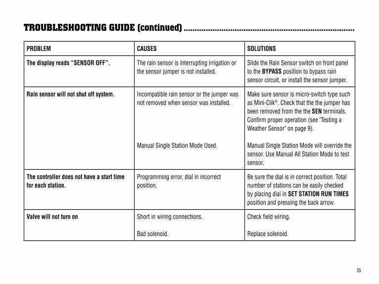
TroUblesHooTInG GUIde (continued) .............................................................................
PROBLEM CAUSES SOLUTIONS
The display reads “SENSOR OFF”. The rain sensor is interrupting irrigation or the sensor jumper is not installed.
Slide the Rain Sensor switch on front panel to the BYPASS position to bypass rain sensor circuit, or install the sensor jumper.
Rain sensor will not shut off system. Incompatible rain sensor or the jumper was not removed when sensor was installed.
Manual Single Station Mode Used.
Make sure sensor is micro-switch type such as Mini-Clik®. Check that the the jumper has been removed from the the SEN terminals. Confirm proper operation (see "Testing a Weather Sensor" on page 9).
Manual Single Station Mode will override the sensor. Use Manual All Station Mode to test sensor.
The controller does not have a start time for each station.
Programming error, dial in incorrect position.
Be sure the dial is in correct position. Total number of stations can be easily checked by placing diai in SET STATION RUN TIMES position and pressing the back arrow.
Valve will not turn on Short in wiring connections. Bad solenoid.
Check field wiring. Replace solenoid.
26
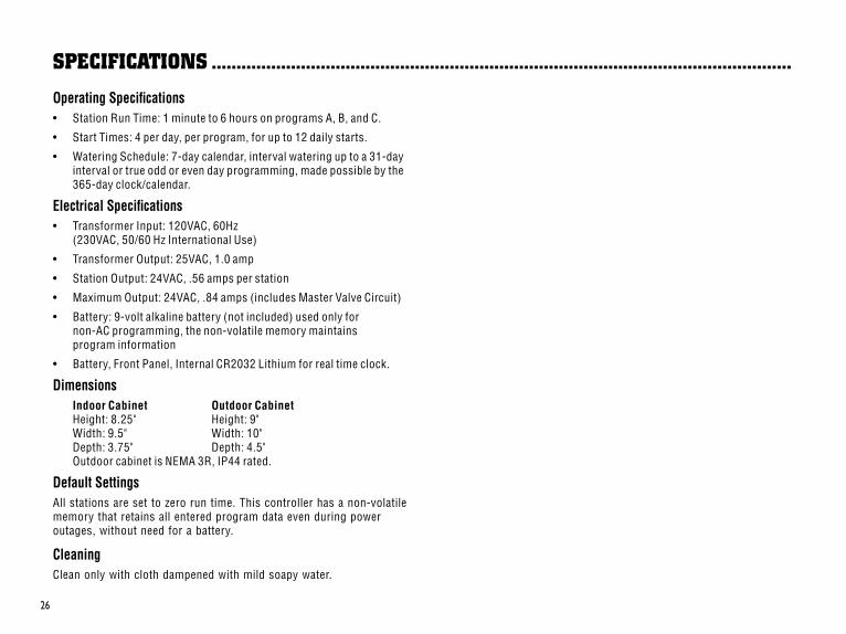
sPeCIfICaTIons .....................................................................................................................
Operating Specifications• Station Run Time: 1 minute to 6 hours on programs A, B, and C.
• Start Times: 4 per day, per program, for up to 12 daily starts.
• Watering Schedule: 7-day calendar, interval watering up to a 31-day interval or true odd or even day programming, made possible by the 365-day clock/calendar.
Electrical Specifications• Transformer Input: 120VAC, 60Hz
(230VAC, 50/60 Hz International Use)
• Transformer Output: 25VAC, 1.0 amp
• Station Output: 24VAC, .56 amps per station
• Maximum Output: 24VAC, .84 amps (includes Master Valve Circuit)
• Battery: 9-volt alkaline battery (not included) used only for non-AC programming, the non-volatile memory maintains program information
• Battery, Front Panel, Internal CR2032 Lithium for real time clock.
Dimensions Indoor Cabinet Outdoor Cabinet
Height: 8.25" Height: 9" Width: 9.5" Width: 10" Depth: 3.75" Depth: 4.5" Outdoor cabinet is NEMA 3R, IP44 rated.
Default SettingsAll stations are set to zero run time. This controller has a non-volatile memory that retains all entered program data even during power outages, without need for a battery.
CleaningClean only with cloth dampened with mild soapy water.

27
fCC noTICe ...............................................................................................................................
This controller generates radio frequency energy and may cause interference to radio and television reception. It has been type tested and found to comply with the limits for a Class B computing device in accordance with the specifications in Subpart J of Part 15 of FCC Rules, which are designed to provide reasonable protection against such interference in a residential installation. However, there is no guarantee that interference will not occur in a particular installation. If this equipment does cause interference to radio or television reception, which can be determined by turning the equipment off and on, the user is encouraged to try to correct the interference by one or more of the following measures:
• Reorient the receiving antenna
• Move the controller away from the receiver
• Plug the controller into a different outlet so that controller and receiver are on different branch circuits
If necessary, the user should consult the dealer or an experienced radio/television technician for additional suggestions. The user may find the following booklet prepared by the Federal Communications Commission helpful: “How to Identify and Resolve Radio-TV Interference Problems.” This booklet is available from the U.S. Government Printing Office, Washington, D.C., Stock No. 004-000-00345-4 (price – $2.00)
Hunter Industries Incorporated • The Irrigation Innovators © 2008 Hunter Industries Incorporated
1940 Diamond Street • San Marcos, California 92078www.HunterIndustries.com P/N 700761 LIT-424 02/08
CerTIfICaTe of ConforMITY To eUroPean dIreCTIVesHunter Industries declares that the irrigation controller Model Pro-C complies with the standards of the European Directives of “electromagnetic compatibility” 87/336/EEC and “low voltage” 73/23/EEC.
__________________________________ Project Engineer
This product should not be used for anything other than what is described in this document. This product should only be serviced by trained and authorized personnel.

Related Documents