RESEARCH Open Access Influence of fibre reinforced polymers in the rehabilitation of damaged masonry wallettes Júnia Soares Nogueira Chagas * and Gray Farias Moita * Correspondence: [email protected] Centro Federal de Educação Tecnológica de Minas Gerais, Av. Amazonas 7675, Nova Gameleira, 30510-000 Belo Horizonte, MG, Brazil Abstract In the past decade, the interest in repair and retrofitting of existing structures and rehabilitation of the damaged structures has led to the development of more effective and low invasive architectural and engineering strategies. In this aspect, the application of fibre reinforced polymer (FRP) strengthening techniques has become reasonably widespread as suitable solutions in addition to the traditional ones. They are promising techniques because of their key characteristics such as: high specific strength, high stiffness, small thickness compared to conventional materials, low influence on the global mass, little durability concerns, ease of handling, flexibility and fast installation that improve on-site productivity, and have a low impact on building functions. In this context, the use of carbon fibre reinforced polymers (CFRP) and glass fibre reinforced polymers (GFRP) for the rehabilitation of damaged small masonry walls (here called wallettes) was investigated experimentally. This study sought to measure the maximum loading carrying capacity of the wallettes and to assess the possible structural rehabilitation in the damaged masonry structures after their reinforcement with the composite polymers. For the adhesion between the wallettes and the reinforcement fibres, primer, putty and a saturant glue epoxy resins were used. Debonding between the FRP composites and the substrate has been recognized as the primary failure mechanism of this reinforcement system and it occurs when the system shear capacity is reached and the FRP is detached from the element. This phenomenon is also addressed in this paper. In general, the experimental results showed the recovery of the original compressive loading bearing capacity of the structures, in spite of the debonding of the FRP composites. Moreover, it could be observed an increasing of up to 39% and up to 49% of the compressive strength for the damaged masonry wallettes reinforced with CFRP and GFRP systems, respectively. The recover (or even rise) in the loading capacity of the reinforced structures due to the external fibres bonding is a good indication of their effectiveness in these situations. Keywords: Rehabilitation; CFRP; GFRP; Masonry; Damage Background The structural masonry is a well-established traditional technology for the construction of affordable buildings. It is widely used throughout the world. Nowadays, simplicity and rationalisation of the construction process, aesthetic correctness, durability, low costs, good thermal and acoustic performance and fire resistance, among others, are characteristics that turn the masonry structures construction system into one of the most economical technology readily available [1]. In Brazil, structural masonry has been extensively used in the construction of the inexpensive buildings since the early © 2015 Chagas and Moita; licensee Springer. This is an Open Access article distributed under the terms of the Creative Commons Attribution License (http://creativecommons.org/licenses/by/4.0), which permits unrestricted use, distribution, and reproduction in any medium, provided the original work is properly credited. Chagas and Moita Applied Adhesion Science (2015) 3:6 DOI 10.1186/s40563-015-0035-3

Welcome message from author
This document is posted to help you gain knowledge. Please leave a comment to let me know what you think about it! Share it to your friends and learn new things together.
Transcript
Chagas and Moita Applied Adhesion Science (2015) 3:6 DOI 10.1186/s40563-015-0035-3
RESEARCH Open Access
Influence of fibre reinforced polymers in therehabilitation of damaged masonry wallettesJúnia Soares Nogueira Chagas* and Gray Farias Moita
* Correspondence:[email protected] Federal de EducaçãoTecnológica de Minas Gerais, Av.Amazonas 7675, Nova Gameleira,30510-000 Belo Horizonte, MG,Brazil
©Am
Abstract
In the past decade, the interest in repair and retrofitting of existing structures andrehabilitation of the damaged structures has led to the development of more effectiveand low invasive architectural and engineering strategies. In this aspect, the applicationof fibre reinforced polymer (FRP) strengthening techniques has become reasonablywidespread as suitable solutions in addition to the traditional ones. They are promisingtechniques because of their key characteristics such as: high specific strength, highstiffness, small thickness compared to conventional materials, low influence on theglobal mass, little durability concerns, ease of handling, flexibility and fast installationthat improve on-site productivity, and have a low impact on building functions. In thiscontext, the use of carbon fibre reinforced polymers (CFRP) and glass fibre reinforcedpolymers (GFRP) for the rehabilitation of damaged small masonry walls (here calledwallettes) was investigated experimentally. This study sought to measure the maximumloading carrying capacity of the wallettes and to assess the possible structural rehabilitationin the damaged masonry structures after their reinforcement with the composite polymers.For the adhesion between the wallettes and the reinforcement fibres, primer, putty and asaturant glue epoxy resins were used. Debonding between the FRP composites and thesubstrate has been recognized as the primary failure mechanism of this reinforcementsystem and it occurs when the system shear capacity is reached and the FRP is detachedfrom the element. This phenomenon is also addressed in this paper. In general, theexperimental results showed the recovery of the original compressive loading bearingcapacity of the structures, in spite of the debonding of the FRP composites. Moreover, itcould be observed an increasing of up to 39% and up to 49% of the compressive strengthfor the damaged masonry wallettes reinforced with CFRP and GFRP systems, respectively.The recover (or even rise) in the loading capacity of the reinforced structures due to theexternal fibres bonding is a good indication of their effectiveness in these situations.
Keywords: Rehabilitation; CFRP; GFRP; Masonry; Damage
BackgroundThe structural masonry is a well-established traditional technology for the construction
of affordable buildings. It is widely used throughout the world. Nowadays, simplicity
and rationalisation of the construction process, aesthetic correctness, durability, low
costs, good thermal and acoustic performance and fire resistance, among others, are
characteristics that turn the masonry structures construction system into one of the
most economical technology readily available [1]. In Brazil, structural masonry has
been extensively used in the construction of the inexpensive buildings since the early
2015 Chagas and Moita; licensee Springer. This is an Open Access article distributed under the terms of the Creative Commonsttribution License (http://creativecommons.org/licenses/by/4.0), which permits unrestricted use, distribution, and reproduction in anyedium, provided the original work is properly credited.

Chagas and Moita Applied Adhesion Science (2015) 3:6 Page 2 of 15
1960’s and, up to now, represents one of the promising solutions for the housing deficit
in the country.
Nonetheless, problems with structural pathologies, failures and collapses have been
reported. They are the result of the lack of more rigorous quality control for the mate-
rials and inadequate production processes. In some cases, these problems also occur
due to the application of inaccurate empirical dimensioning methods, without the wide
use of computational tools, which would yield a more accurate structural analysis re-
sults. In addition to these factors, others contribute to aggravate these problems, such
as: the application of unpredicted loads, due to different uses and architectural modifi-
cations of the structure; foundation settlement; wrong structural conception; natural
deterioration of the materials and components; and, impacts, collisions or explosions.
In such situations, the reinforcement or rehabilitation of the damaged existing struc-
tures have been, often, more attractive or desirable than replacing it with a new con-
struction due to heritage, economic and environmental reasons [2].
The adoption of low invasive and high efficient strengthening techniques is one im-
portant aspect for the success and viability of the rehabilitation interventions. With this
in mind, the usage of fibre reinforced polymers (FRP) to enhance the structural per-
formance of masonry structures is a promising technique because of its high specific
strength, high stiffness and small thickness compared to the conventional materials [3].
In the literature, numerous studies on the strengthening of reinforced concrete struc-
tures with externally bonded FRP sheets have been published for many years. However,
only more recently, experimental and numerical researches have been conducted about
the usage of the FRP for the structural rehabilitation and strengthening of masonry
walls. Very good results have been reported, what contribute to the success on this ap-
proach [4-7]. Nonetheless, only few contributions refer to aspects concerning to the
bonding and debonding behaviour between the masonry elements and the strengthen-
ing system.
The effectiveness of the reinforcement and the failure behaviour of fibre reinforced
masonry structures are strongly influenced by the properties of the substrate where the
reinforcement is applied. Therefore, this factor requires to be further explored. In fact,
the stress concentrations occurring at the FRP/substrate interface could lead to the de-
tachment of the reinforcement from the support and to the premature failure of the
structure due to debonding [8]. The bonding behaviour of the FRP reinforcements on
masonry surface has been investigated and theoretical formulations have been sug-
gested by a specific Italian guide document, which are derived from the approach for
concrete structures [9].
More recently, specific experimental tests were developed to investigate the nature of
the bonding between composite reinforcements and masonry substrates. Moreover, the
mechanism of debonding has been studied considering the influence of various factors,
such as, bond length, geometry of the specimen, tests set-up, and type of the fibre re-
inforcing system. It also can be observed that the wide variety of the masonry sub-
strates, formed by clay or concrete bricks (or blocks), affects the overall performance of
the reinforcement system [10-14].
In this work, a set of small masonry walls was built using concrete blocks. Three
specimens, considered as the reference ones, were subjected to axial compressive load-
ing up to their collapse in order to induce damage to the wallettes. Seven other

Chagas and Moita Applied Adhesion Science (2015) 3:6 Page 3 of 15
specimens were submitted to axial compressive loading of 75% of the average collapse
loading of the reference wallettes. As far as the mechanical behaviour is concerned, ma-
sonry structures subjected to a loading of 75% of their failure threshold is considered
to be completely (structurally) damaged, which can be characterised by the appearance
of randomly distributed cracks or micro-cracks throughout the specimens.
The damaged specimens were then prepared and strengthened by the application of
carbon fibre reinforced polymers (CFRP) or glass fibre reinforced polymers (GFRP),
completely covering both their two main surfaces, as shown in Figure 1. An adequate
chemical and physical bonding between the polymeric fibre and the substrate of the
masonry was utilized. After the application of the reinforcement system, the wallettes
were once again subjected to a vertical compressive load up to their collapse. This
study measured the maximum loading bearing capacity of the wallettes and assessed
the possible structural rehabilitation in the damaged masonry structures after the
reinforcement with the FRP.
MethodsMaterials characterisation and preparation of the specimens
The masonry wallettes used in this research were built using concrete blocks and 1:2:6
(cement: hydrated lime: sand) mortar and had the following dimensions: height =
100 cm; length = 80 cm; thickness = 14 cm, as shown in Figure 1. Two different block
sizes were utilised to build of the wallettes: (a) single-hole blocks (dimensions: 14 cm x
Figure 1 Geometric configuration of the wallettes, with the applied compressive loading. (a) frontalview and (b) top view, with indication of the FRP reinforcement. Dimensions in centimetres.
Chagas and Moita Applied Adhesion Science (2015) 3:6 Page 4 of 15
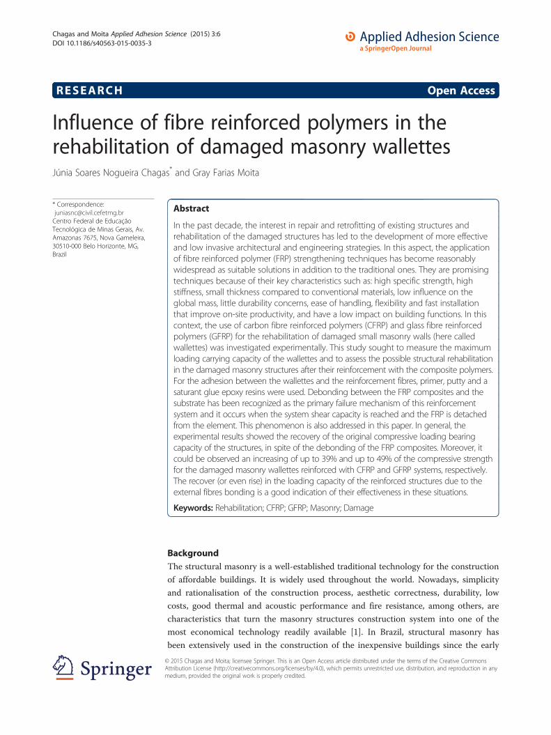
19 cm x 19 cm), and (b) two-hole blocks (dimensions: 14 cm x 19 cm x 39 cm),
depicted in Figure 2, in order to allow the desired geometric configuration of the
panels. Their average compressive strengths were, respectively, 6.30 MPa and
5.64 MPa. The mean compressive strength for the mortar specimens was 6.49 MPa.
The experiments for the characterisation of the mechanical properties of these mate-
rials were conducted according to the Brazilian standards NBR 12118/2013 [15] and
13279/2005 [16], respectively.
Three specimens of the walletes, namely RW1, RW2 and RW3, were built as sche-
matic illustrated in Figure 1. Subsequently, they were subjected to axial compressive
loading up to failure, which meant a mean load of 427 kN. The load was applied per-
pendicularly to the bed joints, in increments of the 2 kN, in an universal testing ma-
chine under vertical displacement control. During the loading, the strains along the
loading axis were calculated using the average displacement measurements obtained
from four dial gauges placed in the panels, two in each of the main sides. The test setup
was established in accordance with the Brazilian standard NBR 15961-2/2011 [17].
These samples were considered the reference wallettes.
In order to cause damage to the wallettes, the seven remaining specimens were sub-
mitted to axial compressive loading of 75% of the average collapse loading of the refer-
ence wallettes, which resulted in a load of 320 kN. The loading was applied in the same
direction as above. The applied loading was big enough to damage the specimens, as
desired. From the visual inspection, micro-cracks and cracks could be observed in the
blocks and the mortar joints of the structure, i.e., the wallettes were in fact damaged.
Characteristics and mechanical properties of the resins and fibre reinforcement polymers
The reinforcement system was made of polymeric fibre (FRP) and resins. The main
mechanical properties of the FRP used in this work, given by the producer [18], were:
for the CFRP (one-directional fabric mesh), Young’s modulus E = 227 GPa and tensile
strength ft = 3800 MPa; and, for the GFRP (two-directional fabric mesh), E = 68.9 GPa,
and ft = 1517 MPa. Epoxy resins provided the bonding for the reinforcement system.
The resins used were a primer, a saturant and a leveling compound called putty. They
Figure 2 Concrete blocks used, with the axial compressive loading applied during testing(according to NBR 12118/2013). Dimensions in centimetres.

Chagas and Moita Applied Adhesion Science (2015) 3:6 Page 5 of 15
are all two-component materials consisting of resin and hardener. Their main charac-
teristics and mechanical properties are given in Tables 1,2,3.
Preparation of the masonry substrate and application of the reinforcement
Before the application of the fibre reinforcement, the wallettes were prepared using
high pressure water blasting in order remove the powder and any other particles from
the substrate. They were dried in room temperature for 7 days. Subsequently, the dam-
aged specimens were strengthened by the application of one-directional fabric of CFRP.
These wallettes were denominated CW1, CW2, and CW3. The specimens GW1, GW2,
GW3 and GW4 received two-directional fabric of GFRP. The FRP layers covered both
the two main surfaces of all damaged specimens, according to Figure 1.
An adequate chemical and physical bonding between the FRP and the substrate of
the masonry was established. Firstly, the substrate of the wallettes was prepared with
the application one layer of the primer. This primer is a two-component solvent-less
epoxy system which when mixed yields a penetrating medium viscosity compound.
This primer is used to penetrate the pore structure of the cementitious substrates and
to provide a high bonding base coating for the FRP system. The drying of the primer
on the substrate took around 1 hour in room temperature. Figure 3 illustrates the pri-
mer application. Since the damaged wallettes did not present crushed parts, only cracks
or micro-cracks, there was no need to fill the collapsed regions with mortar.
Within a 48-hour period after the drying of the primer, a second layer of the adhesion
system was applied, with a thickness of around 2 mm. This epoxy resin is known as
putty. It was useful for the regularisation of any small surface imperfections and to pro-
vide a smooth surface to which the reinforcement system would be applied. The dry-
ing/hardening of the putty is an exothermic process that lasts around an hour. Figure 4
depicts the substrate regularisation when the putty was used.
The system was glued with a resin denominated saturant applied in two coatings,
again within a 48-hour period to ensure the proper adhesion. This saturant is epoxy
based, solvent free, high strength adhesive. One layer is applied over the primer, or the
putty, already dried. At around one hour, before the saturant became tacky, the FRP
fabric was applied. Within 2 hours, a second layer of saturant was applied on top of the
FRP (Figure 5). Finally, a roller was used to expel any bubbles (Figure 6). The whole
cure process took 7 days in room temperature, ranging between 25 to 35°C.
Table 1 Characteristics and mechanical properties of the primer
Properties
Compressive Tensile Flexural
Yield strength 26.2 MPa 14.5 MPa 24.1 MPa
Strain at yield 4.0% 2.0% 4.0%
Elastic modulus 670 MPa 717 MPa 595 MPa
Ultimate strength 28.3 MPa 17.2 MPa 24.1 MPa
Rupture strain 10% 40% Large deformation with no rupture
Poisson’s ratio _ 0.48
Pot life 40 min at 25°C
Cure Fully cured at 20°C - 7 days

Table 2 Characteristics and mechanical properties of the putty
Properties
Compressive Tensile Flexural
Yield strength 22.8 MPa 12.0 MPa 26.2 MPa
Strain at yield 4.0% 1.5% 4.0%
Elastic modulus 1076 MPa 1800 MPa 895 MPa
Ultimate strength 22.8 MPa 15.2 MPa 27.6 MPa
Rupture strain 10% 7% 7%
Poisson’s ratio _ 0.48 _
Pot life 40 min at 25°C
Cure Fully cured at 20°C - 7 days
Chagas and Moita Applied Adhesion Science (2015) 3:6 Page 6 of 15
The wallettes GW1, GW2, CW2 and CW3 were treated with the putty regularisation.
The remaining walls, CW1, GW3 and GW4, did not receive the putty treatment.
The main direction of the fibre was positioned horizontally in the walls, that is, in
the direction perpendicular to the axial loading application. This configuration was
chosen so that a more effecting enveloping (or confining effect) in the damaged struc-
tures could be obtained. The enveloping mentioned above can be understood as the
wrapping effect on the wallettes, based upon the hypothesis that the thickness of the
walls is much smaller than the FRP covered surfaces. As a result of such a configur-
ation, an increase in the compressive strength and the shear capacity of the structures
was expected.
Axial compressive loading experiments
After the application of the reinforcement system onto the damaged wallettes, they
were again subjected to a vertical compressive loading, up to their collapse. In this sec-
ond loading, the relative vertical displacement was measured until the total load
reached approximately 250 kN, which was around 60% of the reference collapse load.
This procedure prevented damage in the measurement equipment if a sudden
structural fail should occur. The experiments were performed in accordance with
the Brazilian standard NBR15961-2/2011 [17]. For comparison with the reference
wallettes experimental results, the Young’s modulus was also determined for these
reinforced wallettes.
Table 3 Characteristics and mechanical properties of the saturant
Properties
Compressive Tensile Flexural
Yield strength 86.2 MPa 54.0 MPa 138.0 MPa
Strain at yield 5.0% 2.5% 3.8%
Elastic modulus 2620 MPa 3034 MPa 3724 MPa
Ultimate strength 86.2 MPa 55.2 MPa 138.0 MPa
Rupture strain 5.0% 3.5% 5%
Poisson’s ratio _ 0.40 _
Pot life 45 min at 25°C
Cure Fully cured at 20°C - 7 days

Figure 3 Application of the primer on the damaged wallettes.
Figure 4 Putty application.
Chagas and Moita Applied Adhesion Science (2015) 3:6 Page 7 of 15

Figure 5 Application of the saturant resin: (a) first layer and (b) second layer on top of the FRP.
Chagas and Moita Applied Adhesion Science (2015) 3:6 Page 8 of 15
Results and discussionAxial compression results
The results of the experiments of specimens RW1, RW2 and RW3 under compression
are shown in Table 4.
Tables 5 and 6 present the efficiency obtained in the compressive strength for each of
the applied reinforcement systems when compared to the reference wallettes. It can be
noted, in general, that all the tested specimens were able to recover the original
strength (and even achieving higher values).
It can be seen from the tables that the specimens reinforced with CFRP that received
the putty (CW2 and CW3) presented a much better performance in relation to mech-
anical resistance as compared to the wallette that was not prepared with the putty
(CW1). The overall compressive strength gain was up to 39% for CW2 and CW3,
whereas CW1 achieved roughly the reference strength, with a small 4% increase. On
the other hand, the wallettes reinforced with GFRP presented non-uniform results,
which does not allow for a definitive conclusion over their mechanical behaviour: the
wallettes treated with putty presented a compressive strength increasing of 5% and
21%, while those that did not received the putty presented a strength improvement of
17% and 49%, as shown in Table 6.
Figure 6 Roller used to expel bubbles.

Table 4 Compressive strength of the reference wallettes
Wallettes Compressive strength[MPa]
Average compressivestrength [MPa]
Standarddeviation
Variation coefficient[%]
RW1 3.93 3.82 0.10 2.64
RW2 3.75
RW3 3.79
Chagas and Moita Applied Adhesion Science (2015) 3:6 Page 9 of 15
According to the manufacturers, the use of a proper adhesive system does not confer
any extra mechanical strength to the FRP composite, but the adhesive is capable of cre-
ating a link between the substrate and FRP system and is able to distribute the applied
loads. The above results confirm that the bonding between the FRP external
reinforcement and the substrate is one of the key issues for the recovery of load cap-
acity for reinforced structures [9,14].
Young’s modulus and stress-strain behaviour
The Young’s modulus was also determined for the reinforced wallettes and a compari-
son with the reference specimens was made. The results indicated that the reference
(before reinforcement) and the FRP reinforced (after reinforcement) wallettes presented
very similar behaviour under the compressive loading, as shown in Tables 7 and 8.
These results suggest that the stiffness of the wallettes was also recovered after the ap-
plication of the FRP reinforcement.
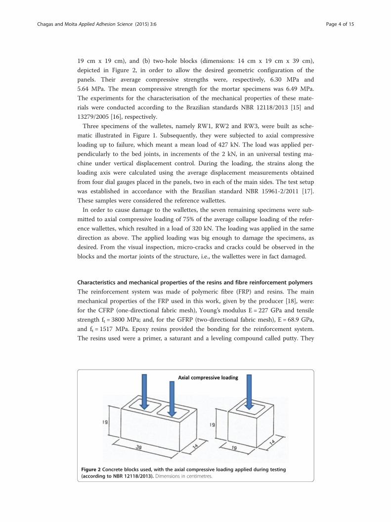
With regard to the stress-strain behaviour, the performance of the wallettes rein-
forced with CFRP was very similar when compared with their GFRP counterpart. Be-
sides, both reinforcement systems presented stress-strain curves comparable to the
curve for the undamaged specimens (before receiving the reinforcement), as depicted
in Figures 7 and 8, indicating the rehabilitation of the strengthened structures.
Failure mode
From the experiments, it could be observed that a fragile, localised and sudden collapse
occurred in the reference wallettes. In the majority of the cases, the cracks started
when the loading approached its failure limit, i.e., approximately 75% of the estimated
maximum load. This confirms the low ductility of the walls and the well-known ex-
pected fragile behaviour of the masonry structures [19].
Moreover, from the experiments in this study, it could be observed that the FRP
reinforcement applied did not exhibit, during the entire loading process, faults or frac-
ture of the adherent that could be visible to the naked eye. Figures 9 and 10 show that
the CFRP reinforced wallettes that received the putty treatment (CW2 and CW3)
Table 5 Obtained efficiency of the wallettes reinforced with one-directional fabric ofCFRP
Wallettes Set up Achieved maximumstrength [MPa]
Reference strength[MPa]
Efficiency Standarddeviation
Variationcoefficient [%]
CW1 Withoutputty
3.96 3.82 1.04 0.77 15.84
CW2 With putty 5.27 1.38
CW3 5.31 1.39

Table 6 Obtained efficiency of the wallettes reinforced with two-directional fabric ofGFRP
Wallettes Set up Achieved maximumstrength [MPa]
Referencestrength [MPa]
Efficiency Standarddeviation
Variationcoefficient [%]
GW1 With putty 4.02 3.82 1.05 0.72 15.28
GW2 4.62 1.21
GW3 Without putty 4.46 1.17
GW4 5.71 1.49
Chagas and Moita Applied Adhesion Science (2015) 3:6 Page 10 of 15
presented failure of the reinforcement system only after the total collapse of the struc-
tures, without presenting fibre debonding, neither between the FRP and the adhesive
system, nor between the concrete substrate and the adhesive system. The failure mode
of the specimen CW2 (Figure 9) suggests that the fibre reinforcement allowed for the
structural masonry wallette to reach its maximum working loading capability, even
after suffering the imposed damaging. Figure 10 brings the failure mode of the CW3
structure, where the fragile rupture of the concrete blocks can be seen. Here, again, no
debonding between the substrate and the adhesive or between the adhesive and the
FRP can be observed. This fact, combined with the maximum loading bearing capacity
shown by the CW2 and CW3 specimens (as in Table 5), implies that the application of
the putty contributes to the rehabilitation, as well as to the increase of the loading bear-
ing capacity, as the result of a better bonding of the reinforcement system to the sub-
strate. However, the CW1 specimen (Figure 11) that did not receive the putty
treatment offered a premature failure when compared with the specimens CW2 and
CW3, as shown in Table 5. From this figure, it is possible to observe the debonding of
the reinforcement fibres, when the wallette reached its original failure loading, i.e., the
lack of bonding of the FRP limited its performance and it only displayed a small load-
ing capacity improvement.
The experimental results confirmed, in general, the recovery of the original compres-
sive loading bearing capacity of the structures. Moreover, it could be seen an increasing
of up to 39% and up to 49% of the compressive strength for the damaged masonry
wallettes reinforced with CFRP and GFRP systems, respectively, as shown in Tables 5
and 6.
The ultimate load attainable by FRP reinforcement depends essentially upon the
compressive and tensile strengths of the substrate. Debonding between the FRP com-
posite and the substrate has been recognised as the principal failure mechanism of the
reinforcement system. Debonding occurs when the system shear capacity is reached
and the FRP reinforcement is detached from the element. Since the substrate is usually
weaker than the glue and the reinforcement, failure is normally associated with the
Table 7 Initial tangential Young’s modulus for the wallettes reinforced with CFRP
Before of the reinforcement After the reinforcement
Wallettes Set up E (MPa) Average value(MPa)
Variationcoefficient (%)
E(MPa)
Averagevalue (MPa)
Variationcoefficient (%)
CW1 Withoutputty
5869 6100 8.50 5625 6170 8.38
CW2 With putty 6110 6653
CW3 6320 6233
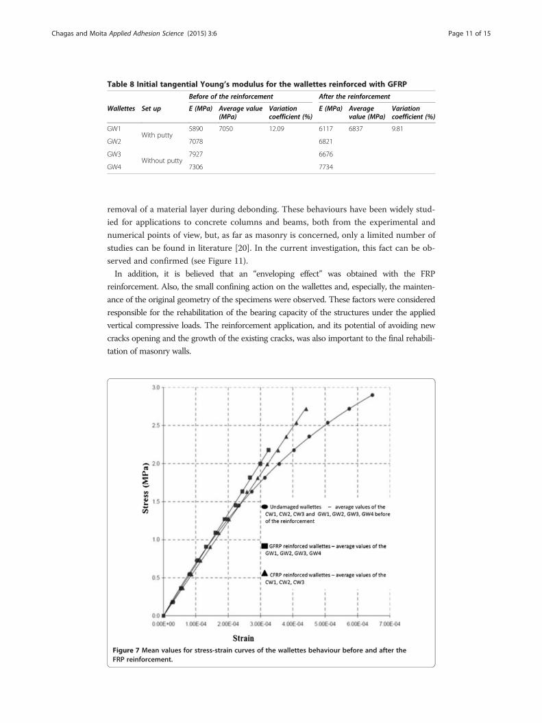
Table 8 Initial tangential Young’s modulus for the wallettes reinforced with GFRP
Before of the reinforcement After the reinforcement
Wallettes Set up E (MPa) Average value(MPa)
Variationcoefficient (%)
E (MPa) Averagevalue (MPa)
Variationcoefficient (%)
GW1With putty
5890 7050 12.09 6117 6837 9.81
GW2 7078 6821
GW3Without putty
7927 6676
GW4 7306 7734
Chagas and Moita Applied Adhesion Science (2015) 3:6 Page 11 of 15
removal of a material layer during debonding. These behaviours have been widely stud-
ied for applications to concrete columns and beams, both from the experimental and
numerical points of view, but, as far as masonry is concerned, only a limited number of
studies can be found in literature [20]. In the current investigation, this fact can be ob-
served and confirmed (see Figure 11).
In addition, it is believed that an “enveloping effect” was obtained with the FRP
reinforcement. Also, the small confining action on the wallettes and, especially, the mainten-
ance of the original geometry of the specimens were observed. These factors were considered
responsible for the rehabilitation of the bearing capacity of the structures under the applied
vertical compressive loads. The reinforcement application, and its potential of avoiding new
cracks opening and the growth of the existing cracks, was also important to the final rehabili-
tation of masonry walls.
Figure 7 Mean values for stress-strain curves of the wallettes behaviour before and after theFRP reinforcement.

Figure 8 Mean values for the load-displacement curves of the wallettes behaviour before and afterthe FRP reinforcement.
Figure 9 Failure of the CW2 wallette reinforced with CFRP (with putty). (a) Frontal view and (b) lateral view.
Chagas and Moita Applied Adhesion Science (2015) 3:6 Page 12 of 15

Figure 10 Failure of the CW3 wallette reinforced with CFRP (with putty).
Figure 11 Failure of the CW1 wallette reinforced with CFRP (without putty).
Chagas and Moita Applied Adhesion Science (2015) 3:6 Page 13 of 15

Chagas and Moita Applied Adhesion Science (2015) 3:6 Page 14 of 15
Finally, it is relevant to comment that the long-term durability of the reinforced
structures was not addressed in the current research.
ConclusionsThe main objective of this work was to present the rehabilitation potential offered by
the CFRP and GFRP applied over previously damaged masonry wallettes. The wallettes
were tested under axial compressive loading, before and after the application of the
FRP reinforcement. It could be noted that the damaged, and later rehabilitated, wal-
lettes could stand the maximum reference loading, with gains of 4% to 49% on the
compressive strength in comparison with the measured failure loading of the undam-
aged reference wallettes. Both CFRP and GFRP reinforced wallettes showed load-
displacement and stress-strain curves similar to those obtained from the reference wal-
lettes. Debonding between the FRP composite and the substrate can be attributed as
premature failure of the reinforcement system and, consequently, of the reinforced wal-
lettes, as observed here. Moreover, the small confining action and the maintenance of
the geometry contributed for rehabilitation of the damaged wallettes.
The increase in the load carrying capacity of the reinforced structures due to the ex-
ternal fibres bonding is a good indication of their effectiveness in these situations.
Hence, the obtained results point out the potential and applicability of the FRP
reinforcement system technique in full-scale problems for masonry structures.
Competing interestsThe authors declare that they have no competing interests.
Authors’ contributionsJSCN and GFM prepared the samples, ran the experiments and wrote the paper. Both authors read and approved thefinal manuscript.
AcknowledgmentsThe authors would like to acknowledge CEFET-MG for their support during the course of this work.
Received: 19 November 2014 Accepted: 16 February 2015
References
1. Hendry AW (2002) Engineered design of masonry buildings: fifty years development in Europe. Prog StructurEngineer Mater 4:291–3002. Asteris PG, Giannopoulos IP (2012) Vulnerability and restoration assessment of masonry structural systems.
Electron J Struct Eng 12:82–933. Hollaway LC, Head PR (2001) Advanced polymer composites and polymers in the civil infrastructure, 1st edn.
Elsevier: Netherlands; pp 109–1554. Masia MJ, Shrive NG (2003) Carbon fibre reinforced polymer wrapping for the rehabilitation of masonry columns.
Can J Civ Eng 30:734–7445. Prakash SS, Alagusundaramoorthy P (2008) Load resistance of masonry wallettes and shear triplets retrofitted with
GFRP composites. Cement Concrete Composites 30:745–7616. Fedele R, Milani G (2010) A numerical insight into the response of masonry reinforced by FRP strips. The case of
perfect adhesion. Compos Struct 92:2345–23577. Faella C, Camorani G, Martinelli E, Paciello SO, Perri F (2012) Bond behaviour of FRP strips glued on masonry:
experimental investigation and empirical formulation. Constr Build Mater 31:353–3638. Grande E, Imbimbo M, Sacco E (2011) Bond behaviour of CFRP laminates on clay bricks: experimental and
numerical study. Compos Part B 42:330–3409. CNR.CNR-DT200 (2006) Guide for the design and construction of externally bonded FRP systems for strengthening
existing structures – materials, RC and PC structures, masonry structures. National Research Council, Rome-CNR,Roma, Italy
10. Benrahou KH, Adda bedia EA, Benyoucef S, Tounsi A, Benguediab M (2006) Interfacial stresses in damaged RCbeams strengthened with externally bonded CFRP plate. Mater Sci Eng A 432:12–19
11. Aiello MA, Sciolti MS (2008) Analysis of bond performance between FRP sheets and calcarenite stones underservice and ultimate condition. J Brit Masonry Soc Masonry Int 21:15–28
12. Mendola LL, Failla A, Cucchiara C, Accardi M (2009) Debonding phenomena in CFRP strengthened calcarenitemasonry walls and vaults. Adv Struct Eng 12:745–760

Chagas and Moita Applied Adhesion Science (2015) 3:6 Page 15 of 15
13. Willis CR, Yanga Q, Seracino R, Griffith MG (2009) Bond behaviour of FRP-to-clay brick masonry joints.Eng Struct 31:25802587
14. Carrara P, Ferretti D, Freddi F (2013) Debonding behavior of ancient masonry elements strengthened with CFRPsheets. Compos Part B 45:800–810
15. ABNT – Associação Brasileira de Normas Técnicas (2013) NBR 12118: Blocos vazados de concreto simples paraalvenaria – Determinação da resistência à compressão. Método de Ensaio: Rio de Janeiro Associação Brasileira deNormas Técnicas.
16. ABNT – Associação Brasileira de Normas Técnicas (2005) NBR13279: Argamassa para assentamento e revestimentode paredes e tetos. Rio de Janeiro: Associação Brasileira de Normas Técnicas.
17. ABNT – Associação Brasileira de Normas Técnicas (2011) NBR 15961-2: Alvenaria estrutural – Blocos de concreto –Parte 2: Execução e controle de obras. Rio de Janeiro Associação Brasileira de Normas Técnicas.
18. Basf, The Chemical Company. 2014. Master Builders Solutions – Technical Data Guide. http://www.master-builders-solutions.basf.us/en-us/products/masterbrace/1507. Accessed 12 October 2014
19. Andreaus U (1996) Failure criteria for masonry panels under in-plane loading. J Struct Eng 122:37–4620. Oliveira DV, Lourenço PB (2011) Experimental bond behaviour of FRP sheets glued on brick masonry. J Compos
Constr 11:319–327
Submit your manuscript to a journal and benefi t from:
7 Convenient online submission
7 Rigorous peer review
7 Immediate publication on acceptance
7 Open access: articles freely available online
7 High visibility within the fi eld
7 Retaining the copyright to your article
Submit your next manuscript at 7 springeropen.com
Related Documents