Research on the Characteristics of Multi-rotor Unmanned Aerial Vehicle Circuit Design and the Anti-jamming of Hardware System Zhaowen Zhang Institute of Oceanographic Instrumentation, Shandong Academy of Sciences, Qingdao, Shandong, 266071, China Abstract. In this paper, according to the demand of system, it puts forward the platform frame structure for the general multi-rotor aircraft controller hardware, In this research, the concept of having modular design is adopted, the layout design of multi-rotor controller circuit board is discussed, and the wiring design of the flight control computer circuit board is also discussed. And the related problems, such as the anti-interference of hardware system and stability of processing and so on are also in consideration. In order to improve the overall reliability of UAV ( Unmanned Aerial Vehicle ) system, a thorough study is carried out. The experiment results showed that the UAV with the hardware system can have reasonable layout and wiring. And the well designed interface of aircraft control circuit board can protect the circuit, which can improve the reliability, stability and anti-interference performance of the aircraft control circuit board. Keywords: Multi-rotor, Unmanned Aerial Vehicle, Anti-jamming Introduction In recent years, UAV has become the focus field of research and development both at home and abroad. Including multi-rotor UAV, fixed wing UAV, small UAV, flapping wing UAV and other kind of aircraft, compared with manned aircraft, UAV can have unparalleled advantages over it. Because there are many flight control system sensor chips, with a lot if input and output channels, besides the interface circuit is rich, in order to meet the requirements, the airborne flight control is designed in small size with light weight. Moreover, in this paper, when the circuit board is designed, the four layer circuit board structure is also designed, each module of the system should be reasonable layout with reasonable wiring at the same time, so as to improve the reliability of the system. PCB design of multi-rotor aircraft controller mainly includes two aspects, namely, layout and wiring, which will be described in the following[1]. Layout Design of Circuit Board of Multi-rotor Aircraft Controller The design of circuit board of multi-rotor aircraft controller is related to many aspects, such as the integrity, performance stability, manufacturability, testability, ease of use and so on. Therefore, layout is very important for the design of circuit board of multi-rotor aircraft controller. Layout can be regarded as the sufficient condition for good wiring. The layout of board of multi-rotor aircraft controller can include three aspects: the use of interface layout, the layout of the major functional modules and the layout of chips within the module[2]. Reasonable layout of the control board of aircraft is very important, the stability of principle circuit should be further ensured by PCB layout, while the negligence on the layout may cause the abnormal operation of some chips, sensitive devices that can not work properly, which can bring out a series of subtle problems. 7th International Conference on Applied Science, Engineering and Technology (ICASET 2017) Copyright © 2017, the Authors. Published by Atlantis Press. This is an open access article under the CC BY-NC license (http://creativecommons.org/licenses/by-nc/4.0/). Advances in Engineering Research, volume 122 270

Welcome message from author
This document is posted to help you gain knowledge. Please leave a comment to let me know what you think about it! Share it to your friends and learn new things together.
Transcript

Research on the Characteristics of Multi-rotor Unmanned Aerial Vehicle
Circuit Design and the Anti-jamming of Hardware System
Zhaowen Zhang
Institute of Oceanographic Instrumentation, Shandong Academy of Sciences, Qingdao, Shandong, 266071, China
Abstract. In this paper, according to the demand of system, it puts forward the platform frame structure for the general multi-rotor aircraft controller hardware, In this research, the concept of having modular design is adopted, the layout design of multi-rotor controller circuit board is discussed, and the wiring design of the flight control computer circuit board is also discussed. And the related problems, such as the anti-interference of hardware system and stability of processing and so on are also in consideration. In order to improve the overall reliability of UAV ( Unmanned Aerial Vehicle ) system, a thorough study is carried out. The experiment results showed that the UAV with the hardware system can have reasonable layout and wiring. And the well designed interface of aircraft control circuit board can protect the circuit, which can improve the reliability, stability and anti-interference performance of the aircraft control circuit board.
Keywords: Multi-rotor, Unmanned Aerial Vehicle, Anti-jamming
Introduction
In recent years, UAV has become the focus field of research and development both at home and abroad. Including multi-rotor UAV, fixed wing UAV, small UAV, flapping wing UAV and other kind of aircraft, compared with manned aircraft, UAV can have unparalleled advantages over it. Because there are many flight control system sensor chips, with a lot if input and output channels, besides the interface circuit is rich, in order to meet the requirements, the airborne flight control is designed in small size with light weight. Moreover, in this paper, when the circuit board is designed, the four layer circuit board structure is also designed, each module of the system should be reasonable layout with reasonable wiring at the same time, so as to improve the reliability of the system. PCB design of multi-rotor aircraft controller mainly includes two aspects, namely, layout and wiring, which will be described in the following[1].
Layout Design of Circuit Board of Multi-rotor Aircraft Controller
The design of circuit board of multi-rotor aircraft controller is related to many aspects, such as the integrity, performance stability, manufacturability, testability, ease of use and so on. Therefore, layout is very important for the design of circuit board of multi-rotor aircraft controller. Layout can be regarded as the sufficient condition for good wiring. The layout of board of multi-rotor aircraft controller can include three aspects: the use of interface layout, the layout of the major functional modules and the layout of chips within the module[2]. Reasonable layout of the control board of aircraft is very important, the stability of principle circuit should be further ensured by PCB layout, while the negligence on the layout may cause the abnormal operation of some chips, sensitive devices that can not work properly, which can bring out a series of subtle problems.
7th International Conference on Applied Science, Engineering and Technology (ICASET 2017)
Copyright © 2017, the Authors. Published by Atlantis Press. This is an open access article under the CC BY-NC license (http://creativecommons.org/licenses/by-nc/4.0/).
Advances in Engineering Research, volume 122
270
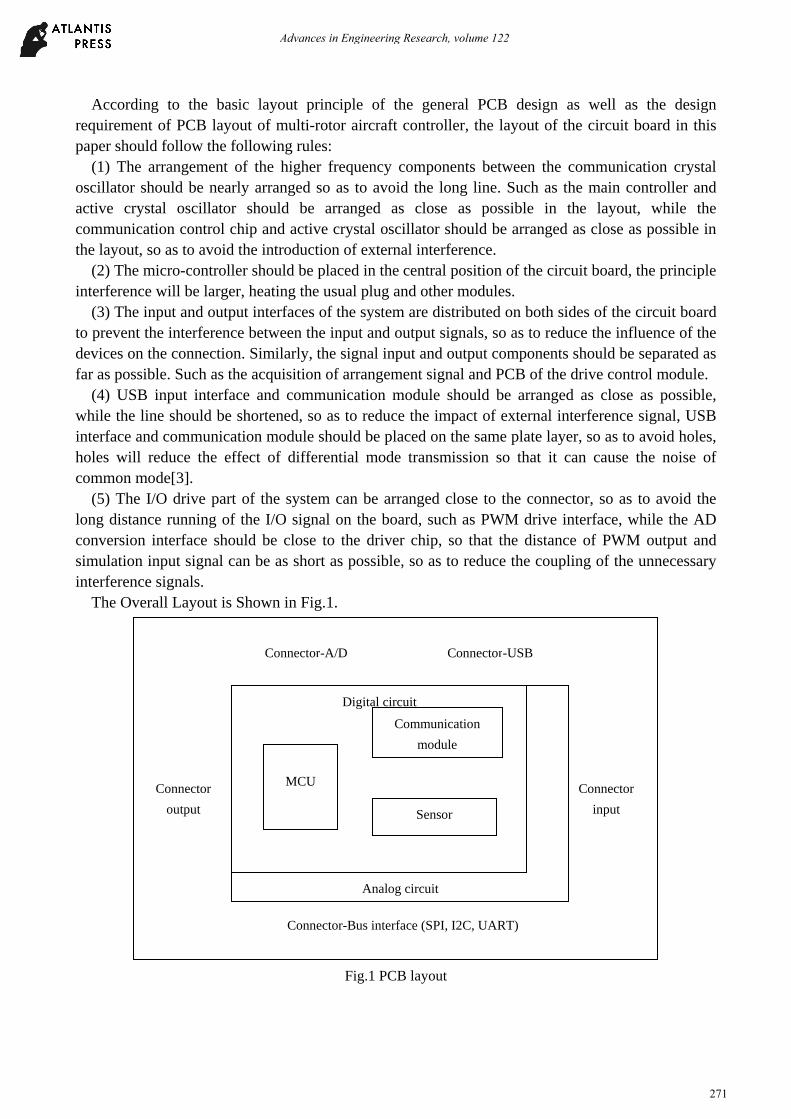
According to the basic layout principle of the general PCB design as well as the design requirement of PCB layout of multi-rotor aircraft controller, the layout of the circuit board in this paper should follow the following rules:
(1) The arrangement of the higher frequency components between the communication crystal oscillator should be nearly arranged so as to avoid the long line. Such as the main controller and active crystal oscillator should be arranged as close as possible in the layout, while the communication control chip and active crystal oscillator should be arranged as close as possible in the layout, so as to avoid the introduction of external interference.
(2) The micro-controller should be placed in the central position of the circuit board, the principle interference will be larger, heating the usual plug and other modules.
(3) The input and output interfaces of the system are distributed on both sides of the circuit board to prevent the interference between the input and output signals, so as to reduce the influence of the devices on the connection. Similarly, the signal input and output components should be separated as far as possible. Such as the acquisition of arrangement signal and PCB of the drive control module.
(4) USB input interface and communication module should be arranged as close as possible, while the line should be shortened, so as to reduce the impact of external interference signal, USB interface and communication module should be placed on the same plate layer, so as to avoid holes, holes will reduce the effect of differential mode transmission so that it can cause the noise of common mode[3].
(5) The I/O drive part of the system can be arranged close to the connector, so as to avoid the long distance running of the I/O signal on the board, such as PWM drive interface, while the AD conversion interface should be close to the driver chip, so that the distance of PWM output and simulation input signal can be as short as possible, so as to reduce the coupling of the unnecessary interference signals.
The Overall Layout is Shown in Fig.1.
Fig.1 PCB layout
Connector-A/D Connector-USB
Connector
output
Connector
input
Analog circuit
Digital circuit
MCU
Communication
module
Sensor
Connector-Bus interface (SPI, I2C, UART)
Advances in Engineering Research, volume 122
271

In order to facilitate the use and convenient test, each connector of multi-rotor aircraft controller on PCB should be dispersed in the periphery of PCB, which should leave enough space to ensure the process of installation and usage can not affect each other.
Wiring Design of Aircraft Control Computer Circuit Board
Wiring is one of the important steps of the aircraft control circuit board, wiring optimization can influence signal quality in a certain extent, especially the synchronous transmission problem of high frequency signal, which can have significant impact on the overall performance of the system. The PCB wiring of this design mainly adopts the following principles and measures:
(1) Adopting four layers circuit board design, the adjacent two wiring layers are designed vertically with each other, so as to reduce the parasitic coupling between boards.
(2) In the micro controller, communication module and USB interface circuit and other relatively high speed circuit[4], wires should adopt straight line as far as possible, when the line must adopt turning, it must adopt 135 degree turning, so as to reduce emission and coupling of the high frequency signal that is generated in the line, which can be shown in Fig. 2.
Fig.2 Connect USB interface and external data memory
(3) In PCB layout design of the main controller, putting particular attention to the connecting line between the micro controller and the external memory expansion, the length of data line and the address line should be consistent, so that the signal delay in each data line can be the same as the address line, so as to ensure the accuracy of data transmission.
(4) The distance between adjacent pads should meet the electrical safety requirements. The width of the wire can be decided according to the size of the current and the manufacturing process. Pad spacing as well as line width should depend on its minimum load current value.
(5) In order to improve the stability of the circuit board and avoid the occasional voltage peak that can be caused by the local area of the circuit board burned[5], holes, pads, wiring spacing should be relaxed as far as possible.
In the design of the ground wire of the circuit board, it is designed to form a closed loop, and the four area of the copper wire should not be left, so as to improve the anti-interference ability of the circuit.
Advances in Engineering Research, volume 122
272
Hardware System Anti-jamming, Stability Processing
According to the design requirements of system, as well as the environmental requirement of small size, light weight, in this paper, in the aspects of circuit design, component selection and other aspects, they can adopt certain security measures.
(1) The electronic governor and the aircraft controller of multi-rotor should be supplied electricity separately, which can adopt stabilizing power supply module with isolation effect module, so as to reduce the interference to the aircraft control circuit during the operation of the external motor.
(2) Self recovery fuse can be used in USB interface, power supply entrance, communication interface, adopting the steady voltage regulator, zener diode, varistor protection components can prevent the damage to the circuit board caused by the reversal connection of power source, surge, as well as the static electricity.
(3) Important line interface can adopt the inverse interpolation processing. Such as GPS interface, external serial port, I2C interface, telemetry data transmission interface and so on, so as to avoid the use of negligence caused by the destruction of the aircraft control board, which can improve the reliability of the system.
(4) In the aspect of installation and usage, we should pay attention to the use of the machine box with electromagnetic shielding effect, as well as the gasket with damping function. As far as possible to reduce the impact of large current and structural vibration during the process of flight.
In particular, during the flying period of the electric multi-rotor, the motor will carry on high-speed rotor which will consume large current, the magnetic field generated by high current will seriously affect the acquisition of electronic magnetic compass for three axis geomagnetic intensity, therefore, it will cause greater error. In this paper, the external magnetic compass is adopted to separate the electronic magnetic compass circuit, which is connected by I2C. When it is used, the magnetic compass module is supported on the position of the rotor arm far from the multi rotor arm, which will reduce the influence of the motor current on the magnetic compass[6].
Around the gyroscope and accelerometer MPU6000, it is better not to have components such as keys that will produce mechanical vibration and stress, within the blank area around 6mm; welded to the PCB plate, it is better to be placed for formation as far as possible, because there is an angle difference between the direction of sensor and the direction of PCB plate, when PCB is rotating around the shaft, it will produce motion that is induced in the other two axial direction; as for welding to the peak re-flow, the temperature of PCB should not be more than 260℃, while is thickness should be less than 1.6 mm of the lead-free welding.
As for the above parts, if the welding environment is too high and the welding temperature is too high, it will lead to the failure of the chip or the large error of the chip output data, which will cause control error and loss.
Conclusion
It is an inevitable trend for the development of era that multi-rotor aircraft will develop from scientific research to application. With the rapid development of microelectronics and micro mechanical manufacturing technology, the application of multi-rotor aircraft will come soon. The task of this paper is to design a multi-rotor aircraft control system based on the requirement of actual application, which should have the features of small size, light weight, high versatility and high performance with less cost. According to the practical needs, it can have reasonable layout and wiring, moreover the well designed interface of aircraft control circuit board can protect the circuit,
Advances in Engineering Research, volume 122
273
which can improve the reliability, stability and anti-interference performance of the aircraft control circuit board.
Reference
[1] HU S, Wang P, CHEN C, et al. Experimental Study on High Temperature-Resistant Gel for Profile Control[J]. Journal of Applied Science and Engineering Innovation, 2015, 2(5): 191-194.
[2] Murilhas, Luis Carlos Margaço. Development of a new system to control and monitor ground vehicles using heterogeneous mobile networks. Diss. 2015.
[3] Wang, Hong Tao, and Zhi Cong Huang. "Remote control methods and systems." U.S. Patent No. 9,397,782. 19 Jul. 2016.
[4] Nitsche M A. Método de navegación basado en aprendizaje y repetición autónoma para vehículos aéreos no tripulados[D]. Facultad de Ciencias Exactas y Naturales. Universidad de Buenos Aires, 2016.
[5] Snyder D J. Design requirements for weaponizing man-portable UAS in support of counter-sniper operations[R]. NAVAL POSTGRADUATE SCHOOL MONTEREY CA, 2011.
[6] Rui H. The Study of Reservoir Properties and Heterogeneities in Block M Oilfield Power[J]. Journal of Applied Science and Engineering Innovation, 2015, 2(11): 424-426.
Advances in Engineering Research, volume 122
274
Related Documents