Research Article Research on Overflow Monitoring Mechanism Based on Downhole Microflow Detection Liang Ge, 1,2 Ze Hu, 3 Ping Chen, 4 Lei Shi, 4 Qing Yang, 1 and Junbi Liao 2 1 College of Mechanical and Electronic Engineering, Southwest Petroleum University, Chengdu 610500, China 2 Department of Measuring and Control, Sichuan University, Chengdu 610065, China 3 College of Electric and Information, Southwest Petroleum University, Chengdu 610500, China 4 State Key Laboratory of Oil & Gas Geology and Exploration, Chengdu 610500, China Correspondence should be addressed to Liang Ge; [email protected] Received 19 October 2014; Revised 12 November 2014; Accepted 18 November 2014; Published 16 December 2014 Academic Editor: Marek Lefik Copyright © 2014 Liang Ge et al. is is an open access article distributed under the Creative Commons Attribution License, which permits unrestricted use, distribution, and reproduction in any medium, provided the original work is properly cited. e flow rate variation of the drilling fluid and micro-overflow loss is difficult to analyze. e purpose to prevent the occurrence of kick, lost circulation, and other complex conditions is not easy to be achieved. erefore, the microflow-induced annulus multiphase flow rate and annulus pressure field model were studied, and a downhole microflow measurement system has been developed. A differential pressure type flow measurement was used in the system, and real-time downhole information was obtained to achieve deep, narrow windows and other safety-density complex formation security. is paper introduced a new bottom-hole flow meter which can measure the annular flux while drilling and monitor overflow and circulation loss. e accuracy and reliability of the MPD (managed pressure drilling) system can be improved obviously by applying the device; as a result, the safety of drilling is enhanced and the cost is reduced. 1. Introduction Along with the rising of total demand of oil and gas resources, the explosion and development of world oil and gas is stepping into the peak gradually [1]. Drilling engineering has become the focus of the oil and gas exploration and devel- opment. For the drilling operation is a hidden underground engineering, which has a large scale, high investments, and high risk, there is a lot of randomness, fuzziness, and uncer- tainty. Because of the misunderstandings of the objective situation or the errors in decision-making of the subjective consciousness, it may cause plenty of complex situations and serious disaster. e blowout accident is one of the most common and heavy loss safety accidents [2]. Overflow is the precursor of blowout, which is caused by the unbalance formation pressure of the bottom hole during the drilling process. In the drilling process, overflow will invade the well due to various reasons, which will cause fluid contamination and drilling corrosion without timely detection. Timely and early detection of overflow can prevent blowout accidents, reduce equipment damage caused by blowout, protect personnel and oil and gas resources, reduce environmental pollution, and ensure safe drilling, which plays an important role in the safe and effective development and the utilization of underground oil and gas resources [3]. Currently, to monitor the drilling operation, the mud level of the overflow tanks fixed on the ground is always detected. And then the formation fluid into the well of the overflow traffic can be determined from the mud level according to the principle of equal replacement [4]. However, this approach has two disadvantages: the first one is that when the formation fluid early invades wells; the excess flow is too small and difficult to be detected, which leads to a serious lag; the other one is that the type of overflow cannot be determined. erefore, the existing detection methods cannot detect overflow accurately and reasonable plan cannot be made [5]. By monitoring the downhole microflow, the wellhead back pressure can be controlled and mud density can be finely adjusted to prevent from kick [6] and well leak disasters. en, under safe and fast drilling in the condition of deep narrow mud window can be achieved. erefore, it has become a trend in modern well-control technology to explore Hindawi Publishing Corporation Mathematical Problems in Engineering Volume 2014, Article ID 676290, 6 pages http://dx.doi.org/10.1155/2014/676290

Welcome message from author
This document is posted to help you gain knowledge. Please leave a comment to let me know what you think about it! Share it to your friends and learn new things together.
Transcript
Research ArticleResearch on Overflow Monitoring MechanismBased on Downhole Microflow Detection
Liang Ge12 Ze Hu3 Ping Chen4 Lei Shi4 Qing Yang1 and Junbi Liao2
1College of Mechanical and Electronic Engineering Southwest Petroleum University Chengdu 610500 China2Department of Measuring and Control Sichuan University Chengdu 610065 China3College of Electric and Information Southwest Petroleum University Chengdu 610500 China4State Key Laboratory of Oil amp Gas Geology and Exploration Chengdu 610500 China
Correspondence should be addressed to Liang Ge cgroadswpueducn
Received 19 October 2014 Revised 12 November 2014 Accepted 18 November 2014 Published 16 December 2014
Academic Editor Marek Lefik
Copyright copy 2014 Liang Ge et alThis is an open access article distributed under the Creative Commons Attribution License whichpermits unrestricted use distribution and reproduction in any medium provided the original work is properly cited
The flow rate variation of the drilling fluid and micro-overflow loss is difficult to analyze The purpose to prevent the occurrence ofkick lost circulation and other complex conditions is not easy to be achievedTherefore themicroflow-induced annulusmultiphaseflow rate and annulus pressure field model were studied and a downhole microflow measurement system has been developed Adifferential pressure type flow measurement was used in the system and real-time downhole information was obtained to achievedeep narrow windows and other safety-density complex formation security This paper introduced a new bottom-hole flow meterwhich can measure the annular flux while drilling and monitor overflow and circulation loss The accuracy and reliability of theMPD (managed pressure drilling) system can be improved obviously by applying the device as a result the safety of drilling isenhanced and the cost is reduced
1 Introduction
Alongwith the rising of total demand of oil and gas resourcesthe explosion and development of world oil and gas isstepping into the peak gradually [1] Drilling engineering hasbecome the focus of the oil and gas exploration and devel-opment For the drilling operation is a hidden undergroundengineering which has a large scale high investments andhigh risk there is a lot of randomness fuzziness and uncer-tainty Because of the misunderstandings of the objectivesituation or the errors in decision-making of the subjectiveconsciousness it may cause plenty of complex situations andserious disaster The blowout accident is one of the mostcommon and heavy loss safety accidents [2] Overflow isthe precursor of blowout which is caused by the unbalanceformation pressure of the bottom hole during the drillingprocess In the drilling process overflow will invade the welldue to various reasons which will cause fluid contaminationand drilling corrosion without timely detection
Timely and early detection of overflow can preventblowout accidents reduce equipment damage caused by
blowout protect personnel and oil and gas resources reduceenvironmental pollution and ensure safe drilling whichplays an important role in the safe and effective developmentand the utilization of underground oil and gas resources [3]
Currently to monitor the drilling operation the mudlevel of the overflow tanks fixed on the ground is alwaysdetected And then the formation fluid into the well ofthe overflow traffic can be determined from the mud levelaccording to the principle of equal replacement [4] Howeverthis approach has two disadvantages the first one is thatwhen the formation fluid early invades wells the excess flowis too small and difficult to be detected which leads to aserious lag the other one is that the type of overflow cannotbe determined Therefore the existing detection methodscannot detect overflow accurately and reasonable plan cannotbe made [5] By monitoring the downhole microflow thewellhead back pressure can be controlled and mud densitycan be finely adjusted to prevent from kick [6] and well leakdisastersThen under safe and fast drilling in the condition ofdeep narrow mud window can be achieved Therefore it hasbecome a trend inmodernwell-control technology to explore
Hindawi Publishing CorporationMathematical Problems in EngineeringVolume 2014 Article ID 676290 6 pageshttpdxdoiorg1011552014676290
2 Mathematical Problems in Engineering
Mud tank
Figure 1 Block diagram of microflow control system 1 downholemicroflow detection system 2 rotating blowout preventer 3 choke-line manifold 4 ground control system
and study new downhole overflow detection mechanismsand methods especially the technology of timely detection ofoverflow in the drilling processThis also ensures safe drillingand plays an important role in safe and effective utilization ofoil and gas resources
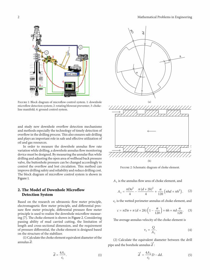
In order to measure the downhole annulus flow ratevariation while drilling a downhole annulus flowmonitoringdevicemust be designed Bymeasuring the annular fluxwhiledrilling and adjusting the open area of wellhead back pressurevalve the buttonhole pressure can be changed accordingly tocontrol the overflow and lost circulation This method canimprove drilling safety and reliability and reduce drilling costThe block diagram of microflow control system is shown inFigure 1
2 The Model of Downhole MicroflowDetection System
Based on the research on ultrasonic flow meter principleelectromagnetic flow meter principle and differential pres-sure flow meter principle differential pressure flow meterprinciple is used to realize the downhole microflow measur-ing [7] The choke element is shown in Figure 2 Consideringpassing ability of mud carried cutting the limitation oflength and cross-sectional dimension and the requirementof pressure differential the choke element is designed basedon the structure of the stabilizer
(1) Calculate the choke element equivalent diameter of theannulus 119889
119889 =41198601
1198881
(1)
120572
120601D
120601d
h
(a)
(b)
Figure 2 Schematic diagram of choke element
1198601is the annulus flow area of choke element and
1198601=1205871198631199002
4minus120587 (119889 + 2ℎ)
2
4+120572
120(120587ℎ119889 + 120587ℎ
2) (2)
1198881is the wetted perimeter annulus of choke element and
119888 = 120587119863119900 + 120587 (119889 + 2ℎ) (1 minus120572
120) + 6ℎ + 120587119889
120572
120 (3)
The average annulus velocity of the choke element is
V1=119876
1198601
(4)
(2) Calculate the equivalent diameter between the drillpipe and the borehole annulus 119889
1015840
1198891015840
=41198602
1198882
119863 minus 119889119889 (5)
Mathematical Problems in Engineering 3
1198602is the cross-sectional area between drill pipe and
wellbore annulus and
1198602=120587 (1198632minus 1198891198892)
4 (6)
1198882is wetted perimeter of drill pipe and wellbore annulus
and
1198882= 120587 (119863 + 119889119889) (7)
The average velocity of the drill pipe annulus is
V2=119876
1198602
(8)
(3) The annulus fluid Reynolds number of the chokeelement is
Re =119889 sdot 120588 sdot V
1
120578119901(1 + (120591
0sdot 119889) (8120578
119901sdot V1)) (9)
For the structure stream 120582 = 96ReFor the turbulent flow 120582 = 0015sim0024The frictional head loss of every choke element is
ℎ1198911= 120582(1198711 cos 120574)119889
V1
2
2119892 (10)
Then the local head loss produced by each choke elementis
ℎ119895= 1205851sdotV1
2
2119892+ 1205852
V1
2
2119892+ 1205853
V1
2
2119892 (11)
1205851is the resistance coefficient sudden expansion of the
local head loss 1205852is the suddenly reduced drag coefficient
of local head loss and 1205853is flow resistance coefficient due to
bendingThe differential pressure caused by each choke element is
Δ119901 = 120588119892 (ℎ1198911+ ℎ119895) (12)
(4)The annulus fluid Reynolds number between the drillpipe and the borehole is
Re =1198891015840
sdot 120588 sdot V2
120578119901(1 + (120591
0sdot 1198891015840
) (8120578119901sdot V2))
(13)
The frictional head loss between the drill pipe andwellbore annulus per unit length is defined by
ℎ1198912= 120582
1
1198891015840
V22
2119892 (14)
For the structure stream 120582 = 96ReFor the turbulent flow 120582 = 0015sim0024(5) The pressure loss from the entrance point to the first
stage chock is calculated by
Δ1199011= 120588119892
119871 minus (1198991198711+ (119899 minus 1) 119871
2)
2sdot ℎ1198912 (15)
(31198711+ 21198712) is the total length of 3-grade chock
1 2 3 45
6 7 8 9 10 11 12 13
14
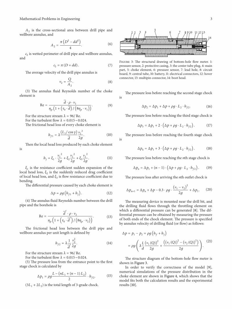
Figure 3 The structural drawing of bottom-hole flow meter 1pressure sensor 2 protective casing 3 the center tube plug 4 mainpart 5 choke element 6 pressure sensor 7 lead hole 8 circuitboard 9 central tube 10 battery 11 electrical connectors 12 hoverconnector 13 multipin connector 14 boot head
The pressure loss before reaching the second stage chockis
Δ1199012= Δ1199011+ Δ119901 + 120588119892 sdot 119871
2sdot ℎ1198912 (16)
The pressure loss before reaching the third stage chock is
Δ1199013= Δ1199011+ 2 sdot (Δ119901 + 120588119892 sdot 119871
2sdot ℎ1198912) (17)
The pressure loss before reaching the fourth stage chockis
Δ1199014= Δ1199011+ 3 sdot (Δ119901 + 120588119892 sdot 119871
2sdot ℎ1198912) (18)
The pressure loss before reaching the 119899th stage chock is
Δ119901119899= Δ1199011+ (119899 minus 1) sdot (Δ119901 + 120588119892 sdot 119871
2sdot ℎ1198912) (19)
The pressure loss after arriving the 119899th outlet chock is
Δ119901119899+1= Δ119901119899+ Δ119901 minus 03 sdot 120588119892 sdot
(V1minus V2)2
2119892+ Δ1199011 (20)
The measuring device is mounted near the drill bit andthe drilling fluid flows through the throttling element onwhich a differential pressure can be generated [8] The dif-ferential pressure can be obtained by measuring the pressureof both ends of the chock element The pressure is specifiedby annulus velocity of drilling fluid (or flow) as follows
Δ119901 = 1199011minus 1199012= 120588119892 (ℎ
119891+ ℎ119895)
= 120588119892(120582119871
119889
(V1(119876))2
2119892+((V1(119876))2
minus (V2(119876))2
)
2119892)
(21)
The structure diagram of the bottom-hole flow meter isshown in Figure 3
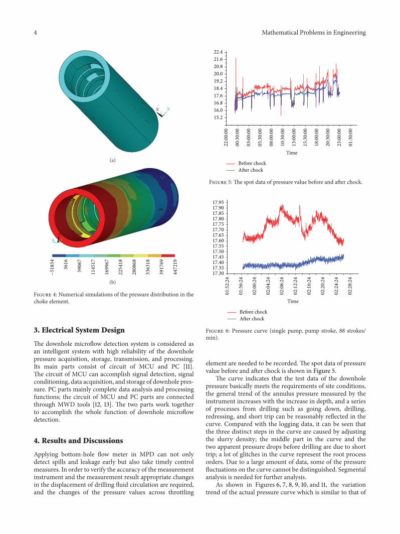
In order to verify the correctness of the model [9]numerical simulations of the pressure distribution in thechoke element are shown in Figure 4 which shows that themodel fits both the calculation results and the experimentalresults [10]
4 Mathematical Problems in Engineering
(a)
minus51834
3616
59067
114517
169967
225418
280868
336318
391769
447219
(b)
Figure 4 Numerical simulations of the pressure distribution in thechoke element
3 Electrical System Design
The downhole microflow detection system is considered asan intelligent system with high reliability of the downholepressure acquisition storage transmission and processingIts main parts consist of circuit of MCU and PC [11]The circuit of MCU can accomplish signal detection signalconditioning data acquisition and storage of downhole pres-sure PC parts mainly complete data analysis and processingfunctions the circuit of MCU and PC parts are connectedthrough MWD tools [12 13] The two parts work togetherto accomplish the whole function of downhole microflowdetection
4 Results and Discussions
Applying bottom-hole flow meter in MPD can not onlydetect spills and leakage early but also take timely controlmeasures In order to verify the accuracy of the measurementinstrument and the measurement result appropriate changesin the displacement of drilling fluid circulation are requiredand the changes of the pressure values across throttling
220
000
003
000
030
000
053
000
080
000
103
000
130
000
153
000
180
000
203
000
230
000
013
000
152160168176184192200208216224
Before chock
Time
After chock
Figure 5 The spot data of pressure value before and after chock
015
224
015
624
020
024
020
424
020
824
021
224
021
624
022
024
022
424
022
824
17301735174017451750175517601765177017751780178517901795
Before chock
Time
After chock
Figure 6 Pressure curve (single pump pump stroke 88 strokesmin)
element are needed to be recorded The spot data of pressurevalue before and after chock is shown in Figure 5
The curve indicates that the test data of the downholepressure basically meets the requirements of site conditionsthe general trend of the annulus pressure measured by theinstrument increases with the increase in depth and a seriesof processes from drilling such as going down drillingredressing and short trip can be reasonably reflected in thecurve Compared with the logging data it can be seen thatthe three distinct steps in the curve are caused by adjustingthe slurry density the middle part in the curve and thetwo apparent pressure drops before drilling are due to shorttrip a lot of glitches in the curve represent the root processorders Due to a large amount of data some of the pressurefluctuations on the curve cannot be distinguished Segmentalanalysis is needed for further analysis
As shown in Figures 6 7 8 9 10 and 11 the variationtrend of the actual pressure curve which is similar to that of
Mathematical Problems in Engineering 5
023
236
023
536
023
836
024
136
024
436
024
736
025
036
025
336
025
636
025
936
030
236
030
536
174017451750175517601765177017751780178517901795180018051810
Before chock
Time
After chock
Figure 7 Pressure curve (single pump pump stroke 92 strokesmin)
030
900
031
200
031
500
031
800
032
100
032
400
032
700
033
000
033
300
033
600
033
900
034
200
17551760176517701775178017851790179518001805181018151820
Before chock
Time
After chock
Figure 8 Pressure curve (single pump pump stroke 96 strokesmin)
the theoretical pressure curve is increased with the increaseof displacement After data processing and operation therelation table between the mud displacement and the dif-ferential pressure is established and the relation table isshown in Table 1 However there are some fluctuations in theactual pressure curve which indicates that the downhole testenvironment is disturbed in some degree during the test
5 Conclusions
As the development of drilling technique a new techniquecalled MPD has been developed on the basis of conventionaldrilling and UBD (under balance drilling) in the past fewyears [14ndash16] This technique has been applied in some oilfields by now and good results have been obtained Howeveras a new technique MPD still has some problems in theory
042
336
042
629
042
922
043
215
043
507
043
800
044
053
044
346
044
639
044
931
045
224
045
517
045
810
177817921806182018341848186218761890
Time
Before chockAfter chock
Figure 9 Pressure curve (double pump pump stroke 104 strokesmin)
045
736
050
029
050
322
050
615
050
907
051
200
051
453
051
746
052
039
052
331
052
624
052
917
053
210
175
177
179
181
183
185
187
189
Before chock
Time
After chock
Figure 10 Pressure curve (double pump pump stroke 112 strokesmin)
Table 1 The relation table between the mud displacement and thedifferential pressure
Mud displacement (Lmin) Pressure difference (MPa)272 0352754 0392856 04289 0432958 0473332 059
and hardware to be solved The downhole microflow mea-suring device developed in this paper measures downholeannulus flow ratewhile drilling and early detects kick andwellleak The application of the device will greatly improve thecurrent process of drilling well control capabilities decrease
6 Mathematical Problems in Engineering
061
336
061
629
061
922
062
215
062
507
062
800
063
053
063
346
063
639
063
931
064
224
064
517
064
810
176177178179180181182183184185186187188189
Before chock
Time
After chock
Figure 11 Pressure curve (double pump pump stroke 116 strokesmin)
the overflow and drainwells to aminimumextent and reducedisaster risks
Conflict of Interests
The authors declare that there is no conflict of interestsregarding the publication of this paper
Acknowledgments
Thiswork is supported by Scientific Research Starting Projectof SWPU (no 2014QHZ029) National Natural Science Foun-dation of China (no 21204139) and the State Administrationof National Security (no sichuan-009-2013AQ)
References
[1] HM Santos K JMuir P Sonnemann J R Kozicz andCHoltldquoOptimizing and automating pressurized mud cap drilling withthe micro-flux control methodrdquo in Proceedings of the SPE AsiaPacific Oil and Gas Conference and Exhibition Perth AustraliaOctober 2008
[2] P Vieira M Arnone I Cook et al ldquoConstant bottomholepressure managed-pressure drilling technique applied in anexploratory well in Saudi Arabiardquo in Proceedings of the SPEIADCManaged Pressure Drilling andUnderbalancedOperationsConference and Exhibition SPE-113679-MS Abu Dhabi UAEJanuary 2010
[3] J C Beltran O Gabaldon G Puerto-Corredor V Varonand P Alvarado ldquoCase studiesmdashproactive managed pressuredrilling and underbalanced drilling application in San Joaquinwells Venezuelardquo in Proceedings of the SPE Annual TechnicalConference and Exhibition SPE-100927-MS San Antonio TexUSA September 2006
[4] AMA R Shaikh ldquo3Dmanaged-pressure drilling around a saltdome using coiled tubing a case studymdashchallenges and solu-tionsrdquo in Proceedings of the Abu Dhabi International Petroleum
Exhibition and Conference SPE-102608-MS Abu Dhabi UAENovember 2006
[5] H Santos P Reid and A Lage ldquoOpening new explorationfrontiers with the micro-flux control methodrdquo in Proceedings ofthe Offshore Technology Conference OTC-16622-MS HoustonTex USA May 2004
[6] R Soto J Malave M Medina and C Dıaz ldquoManaged PressureDrilling (MPD) planning a solution for San Joaquin fieldVenezuelardquo in Proceedings of the IADCSPE Drilling ConferenceSPE-99116-MS Miami Fla USA February 2006
[7] L A Carlsen G Nygaard and M Nikolaou ldquoEvaluation ofcontrol methods for drilling operations with unexpected gasinfluxrdquo Journal of Process Control vol 23 no 3 pp 306ndash3162013
[8] G E Liang S U Fu H U Ze L I Qiang and C RongldquoResearch on power line carrier technology for the intelligentdrill piperdquo Advances in Information Sciences and Service Sci-ences vol 5 no 6 pp 892ndash900 2013
[9] Y Qing and D R Davies ldquoGeneralized predictive controlapplied to intelligent production of an oil wellrdquo in Proceedingsof the 6th IEEE Conference on Industrial Electronics and Appli-cations (ICIEA rsquo11) pp 2033ndash2038 IEEE Beijing China June2011
[10] L Shi P Chen Z Hu and Y-J Fu ldquoThe application of bottom-hole flow meter in the MPD systemrdquo Journal of SouthwestPetroleum University vol 32 no 6 pp 89ndash92 2010
[11] G E Liang H U Ze Q Yang J Li and L Xin ldquoResearch ondistributed optical fiber in oil well temperature field measure-ment systemrdquo Information Technology Journal vol 12 no 18 pp4651ndash4654 2013
[12] D P Zhu and E C Yan ldquoAction mode of groundwater onlandslide mass and standard variation curve of landslide stabil-ity when reservoir water risesrdquo Disaster Advances vol 5 no 4pp 721ndash725 2012
[13] S A Solvang C Leuchtenberg I C Gil et al ldquoManagedPressureDrillingResolves PressureDepletionRelated Problemsin theDevelopment of theHPHTKristin Fieldrdquo SPE113672-MS2008
[14] J P Schumacher J D Dowell L R Ribbeck and J CEggemeyer ldquoSubsea mudlift drilling planning and preparationfor the first Subsea field test of a full-scale dual gradient drillingsystem at Green Canyon 136 Gulf of Mexicordquo in Proceedingsof the SPE Annual Technical Conference and Exhibition SPE-71358-MS New Orleans La USA September 2001
[15] P Fontana andG Sjoberg ldquoReeled pipe technology for deepwa-ter drilling utilizing a dual gradient mud systemrdquo in Proceedingsof the IADCSPE Drilling Conference SPE-59160-MS NewOrleans La USA February 2000
[16] A Calderoni G Girola M Maestrami H Santos and C HoltldquoMicroflux control and E-CD continuous circulation valvesallow operator to reach HPHT reservoirs for the first timerdquoin Proceedings of the IADCSPE Managed Pressure Drillingand Underbalanced Operations Conference and Exhibition SPE122270 San Antonio Tex USA February 2009
Submit your manuscripts athttpwwwhindawicom
Hindawi Publishing Corporationhttpwwwhindawicom Volume 2014
MathematicsJournal of
Hindawi Publishing Corporationhttpwwwhindawicom Volume 2014
Mathematical Problems in Engineering
Hindawi Publishing Corporationhttpwwwhindawicom
Differential EquationsInternational Journal of
Volume 2014
Applied MathematicsJournal of
Hindawi Publishing Corporationhttpwwwhindawicom Volume 2014
Probability and StatisticsHindawi Publishing Corporationhttpwwwhindawicom Volume 2014
Journal of
Hindawi Publishing Corporationhttpwwwhindawicom Volume 2014
Mathematical PhysicsAdvances in
Complex AnalysisJournal of
Hindawi Publishing Corporationhttpwwwhindawicom Volume 2014
OptimizationJournal of
Hindawi Publishing Corporationhttpwwwhindawicom Volume 2014
CombinatoricsHindawi Publishing Corporationhttpwwwhindawicom Volume 2014
International Journal of
Hindawi Publishing Corporationhttpwwwhindawicom Volume 2014
Operations ResearchAdvances in
Journal of
Hindawi Publishing Corporationhttpwwwhindawicom Volume 2014
Function Spaces
Abstract and Applied AnalysisHindawi Publishing Corporationhttpwwwhindawicom Volume 2014
International Journal of Mathematics and Mathematical Sciences
Hindawi Publishing Corporationhttpwwwhindawicom Volume 2014
The Scientific World JournalHindawi Publishing Corporation httpwwwhindawicom Volume 2014
Hindawi Publishing Corporationhttpwwwhindawicom Volume 2014
Algebra
Discrete Dynamics in Nature and Society
Hindawi Publishing Corporationhttpwwwhindawicom Volume 2014
Hindawi Publishing Corporationhttpwwwhindawicom Volume 2014
Decision SciencesAdvances in
Discrete MathematicsJournal of
Hindawi Publishing Corporationhttpwwwhindawicom
Volume 2014 Hindawi Publishing Corporationhttpwwwhindawicom Volume 2014
Stochastic AnalysisInternational Journal of
2 Mathematical Problems in Engineering
Mud tank
Figure 1 Block diagram of microflow control system 1 downholemicroflow detection system 2 rotating blowout preventer 3 choke-line manifold 4 ground control system
and study new downhole overflow detection mechanismsand methods especially the technology of timely detection ofoverflow in the drilling processThis also ensures safe drillingand plays an important role in safe and effective utilization ofoil and gas resources
In order to measure the downhole annulus flow ratevariation while drilling a downhole annulus flowmonitoringdevicemust be designed Bymeasuring the annular fluxwhiledrilling and adjusting the open area of wellhead back pressurevalve the buttonhole pressure can be changed accordingly tocontrol the overflow and lost circulation This method canimprove drilling safety and reliability and reduce drilling costThe block diagram of microflow control system is shown inFigure 1
2 The Model of Downhole MicroflowDetection System
Based on the research on ultrasonic flow meter principleelectromagnetic flow meter principle and differential pres-sure flow meter principle differential pressure flow meterprinciple is used to realize the downhole microflow measur-ing [7] The choke element is shown in Figure 2 Consideringpassing ability of mud carried cutting the limitation oflength and cross-sectional dimension and the requirementof pressure differential the choke element is designed basedon the structure of the stabilizer
(1) Calculate the choke element equivalent diameter of theannulus 119889
119889 =41198601
1198881
(1)
120572
120601D
120601d
h
(a)
(b)
Figure 2 Schematic diagram of choke element
1198601is the annulus flow area of choke element and
1198601=1205871198631199002
4minus120587 (119889 + 2ℎ)
2
4+120572
120(120587ℎ119889 + 120587ℎ
2) (2)
1198881is the wetted perimeter annulus of choke element and
119888 = 120587119863119900 + 120587 (119889 + 2ℎ) (1 minus120572
120) + 6ℎ + 120587119889
120572
120 (3)
The average annulus velocity of the choke element is
V1=119876
1198601
(4)
(2) Calculate the equivalent diameter between the drillpipe and the borehole annulus 119889
1015840
1198891015840
=41198602
1198882
119863 minus 119889119889 (5)
Mathematical Problems in Engineering 3
1198602is the cross-sectional area between drill pipe and
wellbore annulus and
1198602=120587 (1198632minus 1198891198892)
4 (6)
1198882is wetted perimeter of drill pipe and wellbore annulus
and
1198882= 120587 (119863 + 119889119889) (7)
The average velocity of the drill pipe annulus is
V2=119876
1198602
(8)
(3) The annulus fluid Reynolds number of the chokeelement is
Re =119889 sdot 120588 sdot V
1
120578119901(1 + (120591
0sdot 119889) (8120578
119901sdot V1)) (9)
For the structure stream 120582 = 96ReFor the turbulent flow 120582 = 0015sim0024The frictional head loss of every choke element is
ℎ1198911= 120582(1198711 cos 120574)119889
V1
2
2119892 (10)
Then the local head loss produced by each choke elementis
ℎ119895= 1205851sdotV1
2
2119892+ 1205852
V1
2
2119892+ 1205853
V1
2
2119892 (11)
1205851is the resistance coefficient sudden expansion of the
local head loss 1205852is the suddenly reduced drag coefficient
of local head loss and 1205853is flow resistance coefficient due to
bendingThe differential pressure caused by each choke element is
Δ119901 = 120588119892 (ℎ1198911+ ℎ119895) (12)
(4)The annulus fluid Reynolds number between the drillpipe and the borehole is
Re =1198891015840
sdot 120588 sdot V2
120578119901(1 + (120591
0sdot 1198891015840
) (8120578119901sdot V2))
(13)
The frictional head loss between the drill pipe andwellbore annulus per unit length is defined by
ℎ1198912= 120582
1
1198891015840
V22
2119892 (14)
For the structure stream 120582 = 96ReFor the turbulent flow 120582 = 0015sim0024(5) The pressure loss from the entrance point to the first
stage chock is calculated by
Δ1199011= 120588119892
119871 minus (1198991198711+ (119899 minus 1) 119871
2)
2sdot ℎ1198912 (15)
(31198711+ 21198712) is the total length of 3-grade chock
1 2 3 45
6 7 8 9 10 11 12 13
14
Figure 3 The structural drawing of bottom-hole flow meter 1pressure sensor 2 protective casing 3 the center tube plug 4 mainpart 5 choke element 6 pressure sensor 7 lead hole 8 circuitboard 9 central tube 10 battery 11 electrical connectors 12 hoverconnector 13 multipin connector 14 boot head
The pressure loss before reaching the second stage chockis
Δ1199012= Δ1199011+ Δ119901 + 120588119892 sdot 119871
2sdot ℎ1198912 (16)
The pressure loss before reaching the third stage chock is
Δ1199013= Δ1199011+ 2 sdot (Δ119901 + 120588119892 sdot 119871
2sdot ℎ1198912) (17)
The pressure loss before reaching the fourth stage chockis
Δ1199014= Δ1199011+ 3 sdot (Δ119901 + 120588119892 sdot 119871
2sdot ℎ1198912) (18)
The pressure loss before reaching the 119899th stage chock is
Δ119901119899= Δ1199011+ (119899 minus 1) sdot (Δ119901 + 120588119892 sdot 119871
2sdot ℎ1198912) (19)
The pressure loss after arriving the 119899th outlet chock is
Δ119901119899+1= Δ119901119899+ Δ119901 minus 03 sdot 120588119892 sdot
(V1minus V2)2
2119892+ Δ1199011 (20)
The measuring device is mounted near the drill bit andthe drilling fluid flows through the throttling element onwhich a differential pressure can be generated [8] The dif-ferential pressure can be obtained by measuring the pressureof both ends of the chock element The pressure is specifiedby annulus velocity of drilling fluid (or flow) as follows
Δ119901 = 1199011minus 1199012= 120588119892 (ℎ
119891+ ℎ119895)
= 120588119892(120582119871
119889
(V1(119876))2
2119892+((V1(119876))2
minus (V2(119876))2
)
2119892)
(21)
The structure diagram of the bottom-hole flow meter isshown in Figure 3
In order to verify the correctness of the model [9]numerical simulations of the pressure distribution in thechoke element are shown in Figure 4 which shows that themodel fits both the calculation results and the experimentalresults [10]
4 Mathematical Problems in Engineering
(a)
minus51834
3616
59067
114517
169967
225418
280868
336318
391769
447219
(b)
Figure 4 Numerical simulations of the pressure distribution in thechoke element
3 Electrical System Design
The downhole microflow detection system is considered asan intelligent system with high reliability of the downholepressure acquisition storage transmission and processingIts main parts consist of circuit of MCU and PC [11]The circuit of MCU can accomplish signal detection signalconditioning data acquisition and storage of downhole pres-sure PC parts mainly complete data analysis and processingfunctions the circuit of MCU and PC parts are connectedthrough MWD tools [12 13] The two parts work togetherto accomplish the whole function of downhole microflowdetection
4 Results and Discussions
Applying bottom-hole flow meter in MPD can not onlydetect spills and leakage early but also take timely controlmeasures In order to verify the accuracy of the measurementinstrument and the measurement result appropriate changesin the displacement of drilling fluid circulation are requiredand the changes of the pressure values across throttling
220
000
003
000
030
000
053
000
080
000
103
000
130
000
153
000
180
000
203
000
230
000
013
000
152160168176184192200208216224
Before chock
Time
After chock
Figure 5 The spot data of pressure value before and after chock
015
224
015
624
020
024
020
424
020
824
021
224
021
624
022
024
022
424
022
824
17301735174017451750175517601765177017751780178517901795
Before chock
Time
After chock
Figure 6 Pressure curve (single pump pump stroke 88 strokesmin)
element are needed to be recorded The spot data of pressurevalue before and after chock is shown in Figure 5
The curve indicates that the test data of the downholepressure basically meets the requirements of site conditionsthe general trend of the annulus pressure measured by theinstrument increases with the increase in depth and a seriesof processes from drilling such as going down drillingredressing and short trip can be reasonably reflected in thecurve Compared with the logging data it can be seen thatthe three distinct steps in the curve are caused by adjustingthe slurry density the middle part in the curve and thetwo apparent pressure drops before drilling are due to shorttrip a lot of glitches in the curve represent the root processorders Due to a large amount of data some of the pressurefluctuations on the curve cannot be distinguished Segmentalanalysis is needed for further analysis
As shown in Figures 6 7 8 9 10 and 11 the variationtrend of the actual pressure curve which is similar to that of
Mathematical Problems in Engineering 5
023
236
023
536
023
836
024
136
024
436
024
736
025
036
025
336
025
636
025
936
030
236
030
536
174017451750175517601765177017751780178517901795180018051810
Before chock
Time
After chock
Figure 7 Pressure curve (single pump pump stroke 92 strokesmin)
030
900
031
200
031
500
031
800
032
100
032
400
032
700
033
000
033
300
033
600
033
900
034
200
17551760176517701775178017851790179518001805181018151820
Before chock
Time
After chock
Figure 8 Pressure curve (single pump pump stroke 96 strokesmin)
the theoretical pressure curve is increased with the increaseof displacement After data processing and operation therelation table between the mud displacement and the dif-ferential pressure is established and the relation table isshown in Table 1 However there are some fluctuations in theactual pressure curve which indicates that the downhole testenvironment is disturbed in some degree during the test
5 Conclusions
As the development of drilling technique a new techniquecalled MPD has been developed on the basis of conventionaldrilling and UBD (under balance drilling) in the past fewyears [14ndash16] This technique has been applied in some oilfields by now and good results have been obtained Howeveras a new technique MPD still has some problems in theory
042
336
042
629
042
922
043
215
043
507
043
800
044
053
044
346
044
639
044
931
045
224
045
517
045
810
177817921806182018341848186218761890
Time
Before chockAfter chock
Figure 9 Pressure curve (double pump pump stroke 104 strokesmin)
045
736
050
029
050
322
050
615
050
907
051
200
051
453
051
746
052
039
052
331
052
624
052
917
053
210
175
177
179
181
183
185
187
189
Before chock
Time
After chock
Figure 10 Pressure curve (double pump pump stroke 112 strokesmin)
Table 1 The relation table between the mud displacement and thedifferential pressure
Mud displacement (Lmin) Pressure difference (MPa)272 0352754 0392856 04289 0432958 0473332 059
and hardware to be solved The downhole microflow mea-suring device developed in this paper measures downholeannulus flow ratewhile drilling and early detects kick andwellleak The application of the device will greatly improve thecurrent process of drilling well control capabilities decrease
6 Mathematical Problems in Engineering
061
336
061
629
061
922
062
215
062
507
062
800
063
053
063
346
063
639
063
931
064
224
064
517
064
810
176177178179180181182183184185186187188189
Before chock
Time
After chock
Figure 11 Pressure curve (double pump pump stroke 116 strokesmin)
the overflow and drainwells to aminimumextent and reducedisaster risks
Conflict of Interests
The authors declare that there is no conflict of interestsregarding the publication of this paper
Acknowledgments
Thiswork is supported by Scientific Research Starting Projectof SWPU (no 2014QHZ029) National Natural Science Foun-dation of China (no 21204139) and the State Administrationof National Security (no sichuan-009-2013AQ)
References
[1] HM Santos K JMuir P Sonnemann J R Kozicz andCHoltldquoOptimizing and automating pressurized mud cap drilling withthe micro-flux control methodrdquo in Proceedings of the SPE AsiaPacific Oil and Gas Conference and Exhibition Perth AustraliaOctober 2008
[2] P Vieira M Arnone I Cook et al ldquoConstant bottomholepressure managed-pressure drilling technique applied in anexploratory well in Saudi Arabiardquo in Proceedings of the SPEIADCManaged Pressure Drilling andUnderbalancedOperationsConference and Exhibition SPE-113679-MS Abu Dhabi UAEJanuary 2010
[3] J C Beltran O Gabaldon G Puerto-Corredor V Varonand P Alvarado ldquoCase studiesmdashproactive managed pressuredrilling and underbalanced drilling application in San Joaquinwells Venezuelardquo in Proceedings of the SPE Annual TechnicalConference and Exhibition SPE-100927-MS San Antonio TexUSA September 2006
[4] AMA R Shaikh ldquo3Dmanaged-pressure drilling around a saltdome using coiled tubing a case studymdashchallenges and solu-tionsrdquo in Proceedings of the Abu Dhabi International Petroleum
Exhibition and Conference SPE-102608-MS Abu Dhabi UAENovember 2006
[5] H Santos P Reid and A Lage ldquoOpening new explorationfrontiers with the micro-flux control methodrdquo in Proceedings ofthe Offshore Technology Conference OTC-16622-MS HoustonTex USA May 2004
[6] R Soto J Malave M Medina and C Dıaz ldquoManaged PressureDrilling (MPD) planning a solution for San Joaquin fieldVenezuelardquo in Proceedings of the IADCSPE Drilling ConferenceSPE-99116-MS Miami Fla USA February 2006
[7] L A Carlsen G Nygaard and M Nikolaou ldquoEvaluation ofcontrol methods for drilling operations with unexpected gasinfluxrdquo Journal of Process Control vol 23 no 3 pp 306ndash3162013
[8] G E Liang S U Fu H U Ze L I Qiang and C RongldquoResearch on power line carrier technology for the intelligentdrill piperdquo Advances in Information Sciences and Service Sci-ences vol 5 no 6 pp 892ndash900 2013
[9] Y Qing and D R Davies ldquoGeneralized predictive controlapplied to intelligent production of an oil wellrdquo in Proceedingsof the 6th IEEE Conference on Industrial Electronics and Appli-cations (ICIEA rsquo11) pp 2033ndash2038 IEEE Beijing China June2011
[10] L Shi P Chen Z Hu and Y-J Fu ldquoThe application of bottom-hole flow meter in the MPD systemrdquo Journal of SouthwestPetroleum University vol 32 no 6 pp 89ndash92 2010
[11] G E Liang H U Ze Q Yang J Li and L Xin ldquoResearch ondistributed optical fiber in oil well temperature field measure-ment systemrdquo Information Technology Journal vol 12 no 18 pp4651ndash4654 2013
[12] D P Zhu and E C Yan ldquoAction mode of groundwater onlandslide mass and standard variation curve of landslide stabil-ity when reservoir water risesrdquo Disaster Advances vol 5 no 4pp 721ndash725 2012
[13] S A Solvang C Leuchtenberg I C Gil et al ldquoManagedPressureDrillingResolves PressureDepletionRelated Problemsin theDevelopment of theHPHTKristin Fieldrdquo SPE113672-MS2008
[14] J P Schumacher J D Dowell L R Ribbeck and J CEggemeyer ldquoSubsea mudlift drilling planning and preparationfor the first Subsea field test of a full-scale dual gradient drillingsystem at Green Canyon 136 Gulf of Mexicordquo in Proceedingsof the SPE Annual Technical Conference and Exhibition SPE-71358-MS New Orleans La USA September 2001
[15] P Fontana andG Sjoberg ldquoReeled pipe technology for deepwa-ter drilling utilizing a dual gradient mud systemrdquo in Proceedingsof the IADCSPE Drilling Conference SPE-59160-MS NewOrleans La USA February 2000
[16] A Calderoni G Girola M Maestrami H Santos and C HoltldquoMicroflux control and E-CD continuous circulation valvesallow operator to reach HPHT reservoirs for the first timerdquoin Proceedings of the IADCSPE Managed Pressure Drillingand Underbalanced Operations Conference and Exhibition SPE122270 San Antonio Tex USA February 2009
Submit your manuscripts athttpwwwhindawicom
Hindawi Publishing Corporationhttpwwwhindawicom Volume 2014
MathematicsJournal of
Hindawi Publishing Corporationhttpwwwhindawicom Volume 2014
Mathematical Problems in Engineering
Hindawi Publishing Corporationhttpwwwhindawicom
Differential EquationsInternational Journal of
Volume 2014
Applied MathematicsJournal of
Hindawi Publishing Corporationhttpwwwhindawicom Volume 2014
Probability and StatisticsHindawi Publishing Corporationhttpwwwhindawicom Volume 2014
Journal of
Hindawi Publishing Corporationhttpwwwhindawicom Volume 2014
Mathematical PhysicsAdvances in
Complex AnalysisJournal of
Hindawi Publishing Corporationhttpwwwhindawicom Volume 2014
OptimizationJournal of
Hindawi Publishing Corporationhttpwwwhindawicom Volume 2014
CombinatoricsHindawi Publishing Corporationhttpwwwhindawicom Volume 2014
International Journal of
Hindawi Publishing Corporationhttpwwwhindawicom Volume 2014
Operations ResearchAdvances in
Journal of
Hindawi Publishing Corporationhttpwwwhindawicom Volume 2014
Function Spaces
Abstract and Applied AnalysisHindawi Publishing Corporationhttpwwwhindawicom Volume 2014
International Journal of Mathematics and Mathematical Sciences
Hindawi Publishing Corporationhttpwwwhindawicom Volume 2014
The Scientific World JournalHindawi Publishing Corporation httpwwwhindawicom Volume 2014
Hindawi Publishing Corporationhttpwwwhindawicom Volume 2014
Algebra
Discrete Dynamics in Nature and Society
Hindawi Publishing Corporationhttpwwwhindawicom Volume 2014
Hindawi Publishing Corporationhttpwwwhindawicom Volume 2014
Decision SciencesAdvances in
Discrete MathematicsJournal of
Hindawi Publishing Corporationhttpwwwhindawicom
Volume 2014 Hindawi Publishing Corporationhttpwwwhindawicom Volume 2014
Stochastic AnalysisInternational Journal of
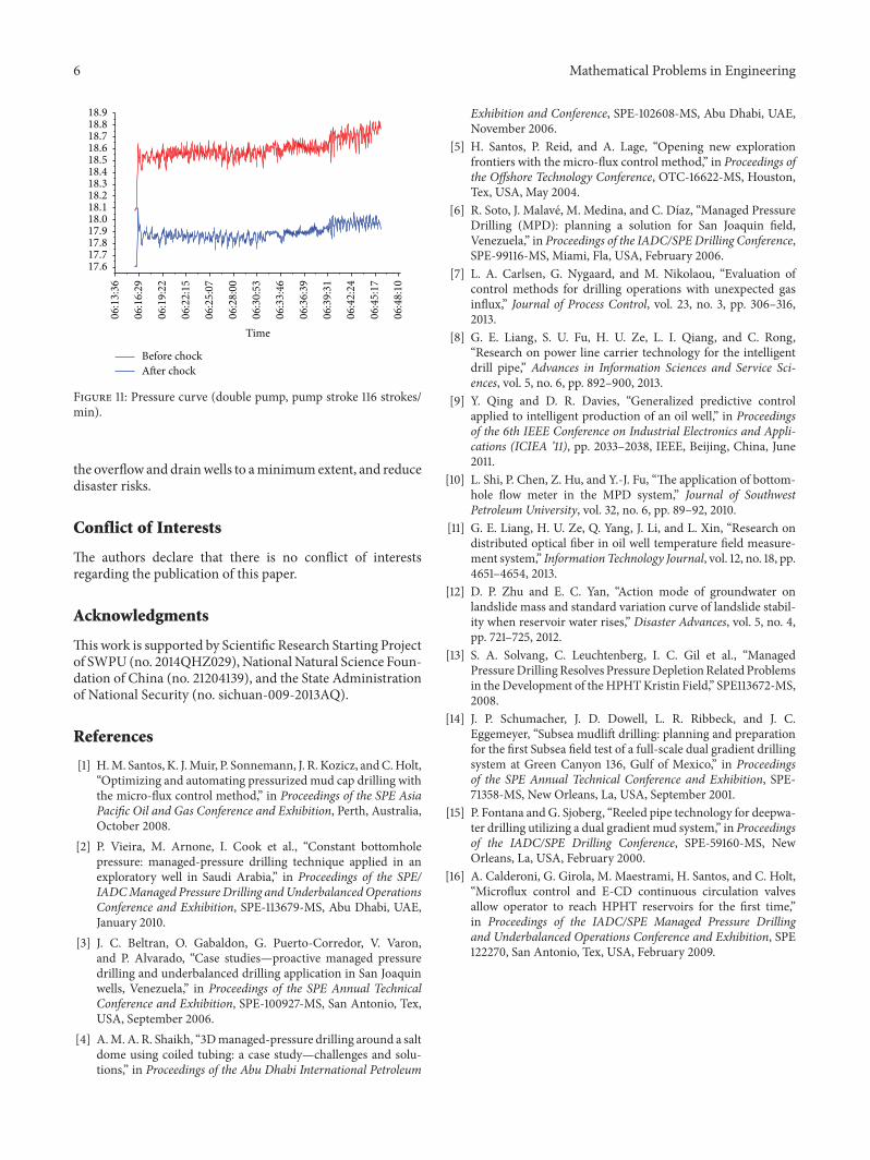
Related Documents