Research On Machining Non-Orthogonal Face Gears By Power Skiving With Tooth Flank Modiヲcation Based On Six-Axis Machine Tool Han ZHENGYANG Northwestern Polytechnical University Jiang CHUANG Henan University of Science and Technology Deng Xiaozhong ( [email protected] ) Henan University of Science and Technology Research Article Keywords: Non-orthogonal face gear, Power skiving, Tooth ァank modiヲcation, Gear cutting Posted Date: November 10th, 2021 DOI: https://doi.org/10.21203/rs.3.rs-1042914/v1 License: This work is licensed under a Creative Commons Attribution 4.0 International License. Read Full License

Welcome message from author
This document is posted to help you gain knowledge. Please leave a comment to let me know what you think about it! Share it to your friends and learn new things together.
Transcript
Research On Machining Non-Orthogonal FaceGears By Power Skiving With Tooth FlankModi�cation Based On Six-Axis Machine ToolHan ZHENGYANG
Northwestern Polytechnical UniversityJiang CHUANG
Henan University of Science and TechnologyDeng Xiaozhong ( [email protected] )
Henan University of Science and Technology
Research Article
Keywords: Non-orthogonal face gear, Power skiving, Tooth �ank modi�cation, Gear cutting
Posted Date: November 10th, 2021
DOI: https://doi.org/10.21203/rs.3.rs-1042914/v1
License: This work is licensed under a Creative Commons Attribution 4.0 International License. Read Full License

Research on machining non-orthogonal face gears by power skiving
with tooth flank modification based on six-axis machine tool
Han ZHENGYANG1, Jiang CHUANG2,3 and Deng XIAOZHONG2,3
Corresponding author: Deng XIAOZHONG
E-mail: [email protected]
1. School of Mechatronic Engineering, Northwestern Polytechnical University,
127 Youyi West Rd, Xi’an 710072, China
2. School of Mechatronics Engineering, Henan University of Science and Technology, 48 Xiyuan Rd, Luoyang 471003, China
3. Collaborative Innovation Center of Machinery Equipment Advanced Manufacturing, Henan University of Science and Technology,
48 Xiyuan Rd, Luoyang 471003, China
Abstract To solve the manufacturing difficulties of non-orthogonal face gear, an efficient gear machining method referred to as power skiving is proposed. The machining principle of the power skiving and the relative position between the cutter tool and the workpiece are analyzed. Then, the mathematical model of machining non-orthogonal face gears by power skiving is established and the tooth flank equation is obtained. The installation and movement mode of non-orthogonal face gears on six-axis machine tool are analyzed and the machining parameters are calculated precisely. A method of tooth flank modification on the six-axis machine tool is presented by changing the machining parameters. The meshing performance of the obtained non-orthogonal face gear is analyzed by an example. Finally, the processing test and the tooth flank measurement are carried out. The experimental results show that the non-orthogonal face gear can be machined and modified by power skiving on the proposed six-axis machine tool. Keywords Non-orthogonal face gear; Power skiving; Tooth flank modification; Gear cutting
1 Introduction
Face gear drives are the precision mechanical transmission matching cylindrical gears to bevel gears. When the cone angle of bevel gear is not 90°, which is called non-orthogonal face gear, it can be used in some non-orthogonal transmission mechanisms, such as helicopter tail transmission, ship propeller and so on. When the cone angle of the bevel gear is 90°, called orthogonal face gears, the teeth of it will be distributed in a plane. Due to the pinion is a cylindrical gear, face gear drives inherit some advantages of cylindrical gear drives, such as insensitive to installation error, the axial position of cylindrical gear has no influence on the contact performance and so on. Face gear drives perform excellently in power splitting, big transmission ratio, low noise and high strength, so it can be used in helicopter main reduction boxes [1].
Face gear drives were first proposed by Buckingham [2] in 1949. In the 1990s, Professor Litvin's team [3-6] carried out a series of researches and discussions on theoretical design and tooth surface modification of face gears and achieved considerable results. In addition, Wang et al. [7, 8] studied honing and griding method for face gears with tooth profile modification. Chu et al. [9] presented a novel method for grinding face gear along contact trace using disk CBN wheel. Kawasaki et al. [10] clarified the effect of the helix angle on the composition of the surface contact lines and proposed a geometric design method that recognizes meshing singularity. At present, the design and calculation
of face gears have a plentiful theoretical foundation. The machining technology of face gears mainly relies on the basic theory of generating surface by gear shaping. Machining methods include face gear hobbing [11], CONIFACE [12], gear milling on machining centers, gear shaping, and powder metallurgy forming. However, these machining methods are mainly aimed at the orthogonal face gears. Due to the particularity of 90° cone angle of orthogonal face gears, it is easier to implement manufacture of the orthogonal face gear in Cartesian coordinate system machine tools. As for non-orthogonal face gear, the machine tool needs to be more flexible due to the diversity of its cone angle. Non-orthogonal face gears are machined mainly rely on the machining center so for. The tooth groove generated by milling cutter on machining center will be limited by the size of the milling cutter. Thus, it is difficult to manufacture the tooth root surface with small transition arc.
Aiming at the difficulties of machining non-orthogonal face gears, this paper proposed machining non-orthogonal face gears by power skiving on the proposed six-axis machine tool. Power skiving, which was proposed by Pittler [13] as early as 1910, is continuous efficient processing method for cylindrical gears. Power skiving requires accurate rotating speed ratio between the cutter tool and the workpiece at high speed. However, due to lacking of proper processing equipment, this novel processing method was not applied in industrial manufacture at that time. With the development of CNC machine tool technology and tool materials, power skiving is gradually favored by industrial development and has been studied by scholars around the world in recent years. For example, Guo et al [14, 15] conducted the fundamental research on the cutting mechanism of cylindrical gear power skiving and proposed a method to design and calculate the skiving tool with the modification coefficient and the tapered teeth for machining involute gears. Chung et al. [16] proposed a simple methodology for automatically and systematically generating the NC code required to manufacture gears using the power-skiving method on a conventional six-axis CNC turn-mill machining center. Numerical control system and tool material technology give full play to high efficiency cutting characteristics of power skiving. However, this gear machining method is only applied to the cylindrical gears at present, especially for internal gears. As for machining face gears by power skiving, there is no relevant information about it so far.
In this paper, power skiving is used for machining non-orthogonal face gears. The processing motion conversion in the proposed six-axis machine tool is realized. An approach to realize tooth surface modification on the machine tool is also presented. An experiment is carried out finally. The results of calculation and experiment show that power skiving is an effective machining method for non-orthogonal face gears. This processing method for machining non-orthogonal face gears can be realized on the six-axis machine tool proposed in this paper.
In this paper, S represents the Cartesian coordinate system. Mmn represents the transformation matrix (4×4) from Sn coordinate system to Sm coordinate system (refer to Appendix A). Tmn represents the transformation matrix (3×3) after removing the last row and the last column of Mmn.
2 Machining scheme of non-orthogonal face gear
The relative cutting speed of power skiving is generated by the rotation of the cutter and the workpiece around their own axes, which are situated in a nonzero shaft angle. Taking the internal gears for example, the shaft angle between the cutter axis and the internal gear axis is Σ0 (see Fig. 1). a1 is the axis of the internal gear and ac is the axis of the cutter. ω1 and ωc are the angular speeds of the internal gear and cutter, respectively. The power skiving cutter can be regarded as a helical gear specially treated. For example, the tooth crest can be designed as a cone to provide the relief
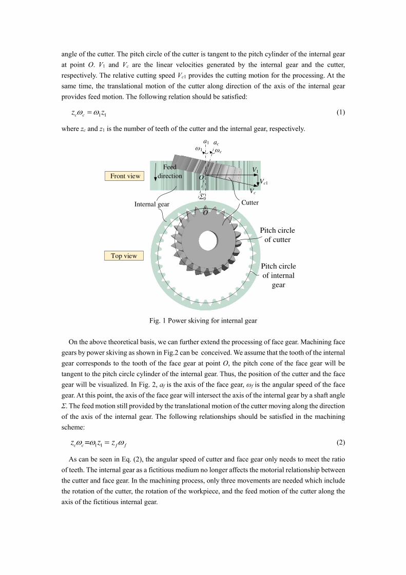
angle of the cutter. The pitch circle of the cutter is tangent to the pitch cylinder of the internal gear at point O. V1 and Vc are the linear velocities generated by the internal gear and the cutter, respectively. The relative cutting speed Vc1 provides the cutting motion for the processing. At the same time, the translational motion of the cutter along direction of the axis of the internal gear provides feed motion. The following relation should be satisfied:
1 1c cz z (1)
where zc and z1 is the number of teeth of the cutter and the internal gear, respectively.
Internal gear
O
Σ0
aca1
V1
Vc
Vc1
ω1 ωc
Cutter
Feed
direction
O
Pitch circle
of cutter
Pitch circle
of internal
gear
Front view
Top view
Fig. 1 Power skiving for internal gear
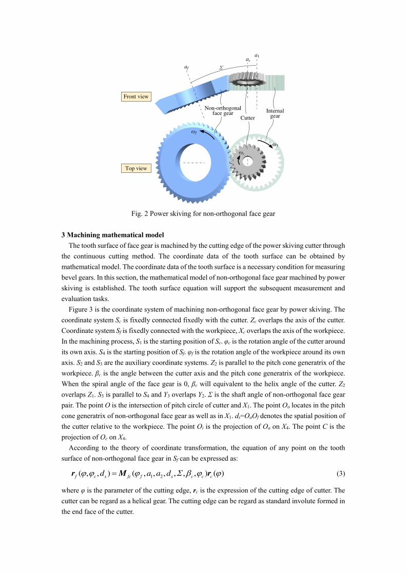
On the above theoretical basis, we can further extend the processing of face gear. Machining face gears by power skiving as shown in Fig.2 can be conceived. We assume that the tooth of the internal gear corresponds to the tooth of the face gear at point O, the pitch cone of the face gear will be tangent to the pitch circle cylinder of the internal gear. Thus, the position of the cutter and the face gear will be visualized. In Fig. 2, af is the axis of the face gear, ωf is the angular speed of the face gear. At this point, the axis of the face gear will intersect the axis of the internal gear by a shaft angle Σ. The feed motion still provided by the translational motion of the cutter moving along the direction of the axis of the internal gear. The following relationships should be satisfied in the machining scheme:
1 1=c c f f
z z z (2)
As can be seen in Eq. (2), the angular speed of cutter and face gear only needs to meet the ratio of teeth. The internal gear as a fictitious medium no longer affects the motorial relationship between the cutter and face gear. In the machining process, only three movements are needed which include the rotation of the cutter, the rotation of the workpiece, and the feed motion of the cutter along the axis of the fictitious internal gear.
Σ
a1
af
ac
ωf
ω1
ωc
Front view
Top view
Non-orthogonal face gear
Cutter
Internal gear
Fig. 2 Power skiving for non-orthogonal face gear
3 Machining mathematical model
The tooth surface of face gear is machined by the cutting edge of the power skiving cutter through the continuous cutting method. The coordinate data of the tooth surface can be obtained by mathematical model. The coordinate data of the tooth surface is a necessary condition for measuring bevel gears. In this section, the mathematical model of non-orthogonal face gear machined by power skiving is established. The tooth surface equation will support the subsequent measurement and evaluation tasks.
Figure 3 is the coordinate system of machining non-orthogonal face gear by power skiving. The coordinate system Sc is fixedly connected fixedly with the cutter. Zc overlaps the axis of the cutter. Coordinate system Sf is fixedly connected with the workpiece, Xc overlaps the axis of the workpiece. In the machining process, S1 is the starting position of Sc. φc is the rotation angle of the cutter around its own axis. S4 is the starting position of Sf. φf is the rotation angle of the workpiece around its own axis. S2 and S3 are the auxiliary coordinate systems. Z2 is parallel to the pitch cone generatrix of the workpiece. βc is the angle between the cutter axis and the pitch cone generatrix of the workpiece. When the spiral angle of the face gear is 0, βc will equivalent to the helix angle of the cutter. Z2 overlaps Z1. S3 is parallel to S4 and Y3 overlaps Y2. Σ is the shaft angle of non-orthogonal face gear pair. The point O is the intersection of pitch circle of cutter and X1. The point Oa locates in the pitch cone generatrix of non-orthogonal face gear as well as in X1. ds=OaOf denotes the spatial position of the cutter relative to the workpiece. The point Oi is the projection of Oa on X4. The point C is the projection of Oc on X4.
According to the theory of coordinate transformation, the equation of any point on the tooth surface of non-orthogonal face gear in Sf can be expressed as:
1 2( , , ) ( , , , , , , ) ( )f c s fc f s c c c
d a a d r M r (3)
where φ is the parameter of the cutting edge, rc is the expression of the cutting edge of cutter. The cutter can be regard as a helical gear. The cutting edge can be regard as standard involute formed in the end face of the cutter.

The transformation matrix is:
1 2 4 43 1 2 32 21 1( , , , , , ) ( ) ( , ) ( ) ( ) ( )fc f c c f f c c c
a a a a M M M M M M (4)
where
1 0
2 0
sin ( )cos
cos ( )sin
/ sin / ( )
c s
f s
f c c f s f f
a O C d r
a O C d r
z z d mz
(5)
where ξ indicates the excess in-feed (which will be used in the modification part below). Δds is the variation of ds. r0 is the pitch radius of the cutter. The sign “±” indicates the hands of non-orthogonal face gear.
The unit normal vector of the tooth surface is:
d d d d( , , ) /
d d d d
f f f f
f c s
s s
dd d
r r r r
n (6)
Xc
Zc,Z1
X1,X2
Z2
Oa
Of
Z3
X3
Y2,Y3
Z4
X4, Xf
Zf
Y4
Yf
Oc
φc
φf
Σ
Σ
Oi
ωc
ωf
βc
Y1
O
C
a1
a2
ds
Fig. 3 Machining coordinate system
Equation (3) represents the tooth surface equation of the non-orthogonal face gear taking the vertex of the pitch cone as the origin of coordinates. This expression should meet the meshing equation as Eq. (7).
1
d d d( , , ) 0
d d d
f f f
s c
s c
f dd
r r r
(7)
The three-dimensional coordinates of any point on the tooth surface of the non-orthogonal face gear can be obtained by solving nonlinear equations when the axial and radial positions of the point
are provided.
4 Machining approach
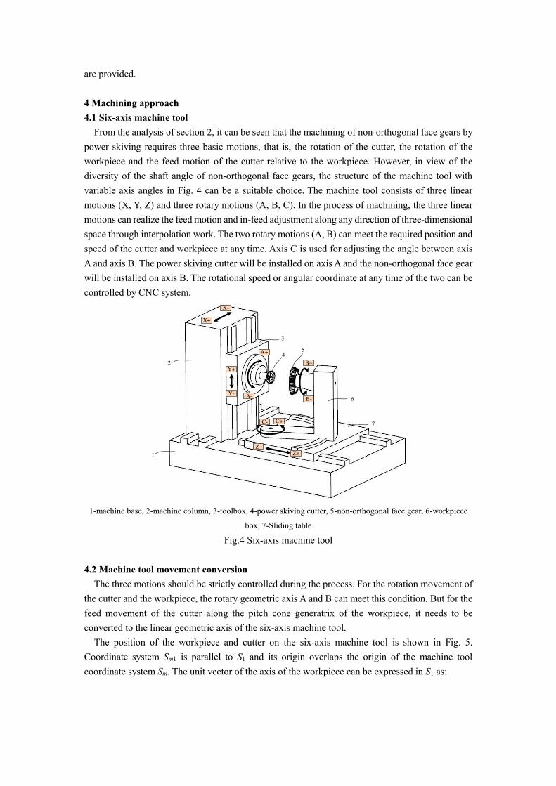
4.1 Six-axis machine tool From the analysis of section 2, it can be seen that the machining of non-orthogonal face gears by
power skiving requires three basic motions, that is, the rotation of the cutter, the rotation of the workpiece and the feed motion of the cutter relative to the workpiece. However, in view of the diversity of the shaft angle of non-orthogonal face gears, the structure of the machine tool with variable axis angles in Fig. 4 can be a suitable choice. The machine tool consists of three linear motions (X, Y, Z) and three rotary motions (A, B, C). In the process of machining, the three linear motions can realize the feed motion and in-feed adjustment along any direction of three-dimensional space through interpolation work. The two rotary motions (A, B) can meet the required position and speed of the cutter and workpiece at any time. Axis C is used for adjusting the angle between axis A and axis B. The power skiving cutter will be installed on axis A and the non-orthogonal face gear will be installed on axis B. The rotational speed or angular coordinate at any time of the two can be controlled by CNC system.
C+C-
Z+
Z-
B+
B-A-
A+
Y+
Y-
X+
X-
1
2
3
45
6
7
1-machine base, 2-machine column, 3-toolbox, 4-power skiving cutter, 5-non-orthogonal face gear, 6-workpiece
box, 7-Sliding table
Fig.4 Six-axis machine tool
4.2 Machine tool movement conversion
The three motions should be strictly controlled during the process. For the rotation movement of the cutter and the workpiece, the rotary geometric axis A and B can meet this condition. But for the feed movement of the cutter along the pitch cone generatrix of the workpiece, it needs to be converted to the linear geometric axis of the six-axis machine tool.
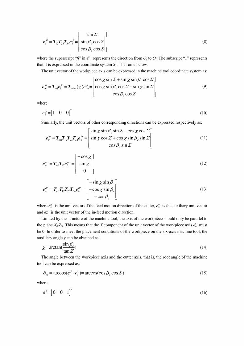
The position of the workpiece and cutter on the six-axis machine tool is shown in Fig. 5. Coordinate system Sm1 is parallel to S1 and its origin overlaps the origin of the machine tool coordinate system Sm. The unit vector of the axis of the workpiece can be expressed in S1 as:
1 12 23 34 4
sin
= sin cos
cos cos
fi fi
c
c
e T T T e (8)
where the superscript “fi” in efi 1 represents the direction from Of to Oi. The subscript “1” represents
that it is expressed in the coordinate system S1. The same below. The unit vector of the workpiece axis can be expressed in the machine tool coordinate system as:
1 1 1 1
cos sin sin sin cos
( ) = cos sin cos sin sin
cos cos
c
fi fi fi
m m m m m c
c
e T e T e (9)
where
4 = 1 0 0Tfi
e (10)
Similarly, the unit vectors of other corresponding directions can be expressed respectively as:
1 12 23 34 4
sin sin sin cos cos
sin cos cos sin sin
cos sin
c
ia ia
m m c
c
e T T T T e (11)
1 12 2
cos
sin
0
ac ac
m m
e T T e (12)
1 12 23 34 4
sin sin
cos sin
cos
c
af af
m m c
c
e T T T T e (13)
where eaf m is the unit vector of the feed motion direction of the cutter, eia
m is the auxiliary unit vector and eac
m is the unit vector of the in-feed motion direction. Limited by the structure of the machine tool, the axis of the workpiece should only be parallel to
the plane XmZm. This means that the Y component of the unit vector of the workpiece axis efi m must
be 0. In order to meet the placement conditions of the workpiece on the six-axis machine tool, the auxiliary angle χ can be obtained as:
sin=arctan( )
tan
c
(14)
The angle between the workpiece axis and the cutter axis, that is, the root angle of the machine tool can be expressed as:
1 1arccos( )=arccos(cos cos )fi c
m c e e (15)
where
1 = 0 0 1Tc
e (16)
Oi
Of
Oc
Om
OfOiOmOi OmOf
OcOc
Zm
Xm
Xm
Ym
Ym
Zm
δm
Y+ view
Z- viewX- view
Axonometric
view
Y1
X1
Y1m
X1m
χOa
Oa
Oa
Fig. 5 Position of cutter and workpiece
According to the principle of vector superposition, the coordinates of the cutter center Oc in the machine tool coordinate system can be expressed as:
( )c fi ia ac
m fi mf m ia m ac mL L L L r e e e (17)
It can be seen from Eq. (13) that the motorial direction involved in the processing of non-orthogonal face gear is only related to the shaft angle, which is between the axis of the cutter and the fictitious internal gear, and the pitch cone angle of the workpiece. When the pitch cone angle of the workpiece is zero, it means that the non-orthogonal face gear has become a cylindrical gear and the root angle of the machine tool will be the shaft angle. At this time the processing of the non-orthogonal face gear has become the processing of the cylindrical gear. When the pitch cone angle of the workpiece is 90°, meaning the workpiece is orthogonal face gear, the root angle of the machine tool will be 90°. The above formulas explain the smooth transition from orthogonal face gear to cylindrical gear.
5 Tooth flank modification
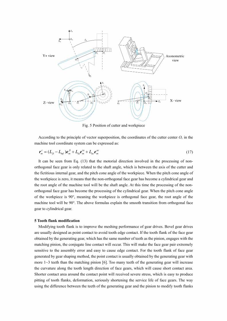
Modifying tooth flank is to improve the meshing performance of gear drives. Bevel gear drives are usually designed as point contact to avoid tooth edge contact. If the tooth flank of the face gear obtained by the generating gear, which has the same number of teeth as the pinion, engages with the matching pinion, the conjugate line contact will occur. This will make the face gear pair extremely sensitive to the assembly error and easy to cause edge contact. For the tooth flank of face gear generated by gear shaping method, the point contact is usually obtained by the generating gear with more 1~3 teeth than the matching pinion [6]. Too many teeth of the generating gear will increase the curvature along the tooth length direction of face gears, which will cause short contact area. Shorter contact area around the contact point will received severe stress, which is easy to produce pitting of tooth flanks, deformation, seriously shortening the service life of face gears. The way using the difference between the teeth of the generating gear and the pinion to modify tooth flanks
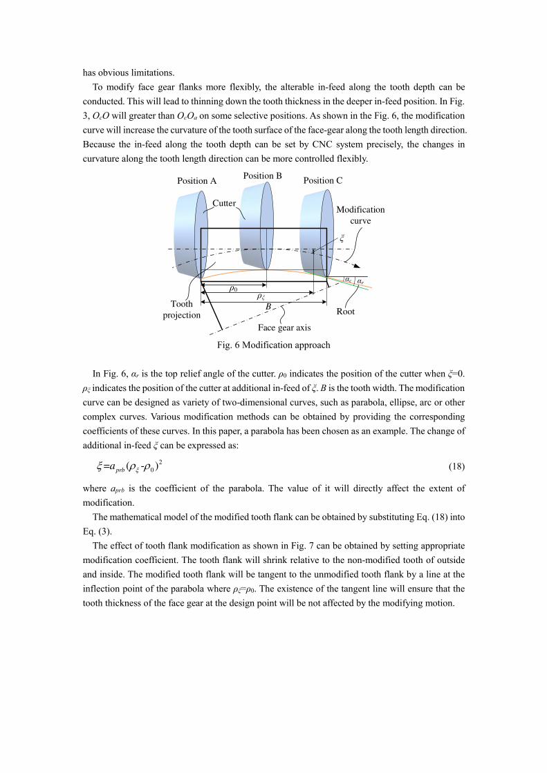
has obvious limitations. To modify face gear flanks more flexibly, the alterable in-feed along the tooth depth can be
conducted. This will lead to thinning down the tooth thickness in the deeper in-feed position. In Fig. 3, OcO will greater than OcOa on some selective positions. As shown in the Fig. 6, the modification curve will increase the curvature of the tooth surface of the face-gear along the tooth length direction. Because the in-feed along the tooth depth can be set by CNC system precisely, the changes in curvature along the tooth length direction can be more controlled flexibly.
Root
Modification
curve
ξ
ρ0
Position APosition B
Position C
Tooth
projectionB
Cutter
αrαc
Face gear axis
ρξ
Fig. 6 Modification approach
In Fig. 6, αr is the top relief angle of the cutter. ρ0 indicates the position of the cutter when ξ=0. ρξ indicates the position of the cutter at additional in-feed of ξ. B is the tooth width. The modification curve can be designed as variety of two-dimensional curves, such as parabola, ellipse, arc or other complex curves. Various modification methods can be obtained by providing the corresponding coefficients of these curves. In this paper, a parabola has been chosen as an example. The change of additional in-feed ξ can be expressed as:
2
0= ( - )prba (18)
where aprb is the coefficient of the parabola. The value of it will directly affect the extent of modification.
The mathematical model of the modified tooth flank can be obtained by substituting Eq. (18) into Eq. (3).
The effect of tooth flank modification as shown in Fig. 7 can be obtained by setting appropriate modification coefficient. The tooth flank will shrink relative to the non-modified tooth of outside and inside. The modified tooth flank will be tangent to the unmodified tooth flank by a line at the inflection point of the parabola where ρξ=ρ0. The existence of the tangent line will ensure that the tooth thickness of the face gear at the design point will be not affected by the modifying motion.

Modified flank
Unmodified flank
Fig. 7 Modification preconception
The cutter moves along the modified curve when the cutter is moving from the outer end to the inner end of the workpiece. This means that the tooth root curve of the non-orthogonal face gear will also be bent accordingly. Since the end face of the cutter is perpendicular to the pitch cone generatrix of the non-orthogonal face gear, the tooth root curve will be parallel to the modified curve. It can be seen from Fig. 6 that when the cutter reaches the inner end of the workpiece, the condition “αr>αc” should be guaranteed to avoid interference. The upper limit of the parabolic coefficient can be expressed as:
0
tan
2( )
rprba
B
(19)
By substituting Eq. (19) into Eq. (18) and taking ρξ=B, the maximum of modification can be obtained:
max 0=( - ) tan / 2rB (20)
6 Geometric analysis of tooth flanks
To obtain better meshing performance, it is significant to analyze the effect of modification on transmission performance of the tooth flanks of non-orthogonal face gear obtained by power skiving. The parameters are determined as shown in Table 1.
Table 1 Illustrative example
Parameters Values
Teeth number of the face gear zf =44
Pressure angle α=25°
Module m=4
Helix angle of the face gear βf =0
Teeth number of the pinion zp=24
Teeth number of the cutter zc=25
Helix angle of the cutter βc=10°R
Relief angle αr=7°
Pitch cone angle Σ=10°
Outer pitch diameter of the face gear do=186 mm
Inner pitch diameter of the face gear di=170 mm
6.1 Flank modification analysis
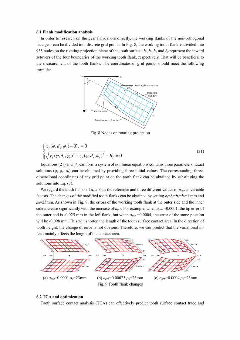
In order to research on the gear flank more directly, the working flanks of the non-orthogonal face gear can be divided into discrete grid points. In Fig. 8, the working tooth flank is divided into 9*5 nodes on the rotating projection plane of the tooth surface. bi, bt, bo and br represent the inward setovers of the four boundaries of the working tooth flank, respectively. That will be beneficial to the measurement of the tooth flanks. The coordinates of grid points should meet the following formula:
Transition curved surface
Working Flank surface
Transition curve
Inspection
boundary
br
bt
bi
bo
Xf
RfOf
Σ
Fig. 8 Nodes on rotating projection
2 2
( , , ) 0
( , , ) ( , , ) 0
f s c f
f s c f s c f
x d X
y d z d R
(21)
Equations (21) and (7) can form a system of nonlinear equations contains three parameters. Exact solutions (φ, φc, ds) can be obtained by providing three initial values. The corresponding three-dimensional coordinates of any grid point on the tooth flank can be obtained by substituting the solutions into Eq. (3).
We regard the tooth flanks of aprb=0 as the reference and three different values of aprb as variable factors. The changes of the modified tooth flanks can be obtained by setting bi=bt=bo=br=1 mm and ρ0=23mm. As shown in Fig. 9, the errors of the working tooth flank at the outer side and the inner side increase significantly with the increase of aprb. For example, when aprb =0.0001, the tip error of the outer end is -0.025 mm in the left flank, but when aprb =0.0004, the error of the same position will be -0.098 mm. This will shorten the length of the tooth surface contact area. In the direction of tooth height, the change of error is not obvious. Therefore, we can predict that the variational in-feed mainly affects the length of the contact area.
(a) aprb=0.0001 ρ0=23mm (b) aprb=0.00025 ρ0=23mm (c) aprb=0.0004 ρ0=23mm
Fig. 9 Tooth flank changes
6.2 TCA and optimization
Tooth surface contact analysis (TCA) can effectively predict tooth surface contact trace and
transmission accuracy. Tooth surface contact needs to meet the conditions:
( ) ( , , ) ( ) ( , )
( ) ( , , ) ( ) ( , )
mf f f c s mp p p p p
mf f f c s mp p p p p
d d
d d
M r M r
T n T n (22)
where rp and np represent the position vector and normal vector of the pinion, respectively. φp and dp are the parameters of the tooth surface of the pinion, respectively. Mmf and Mmp respectively represent the transition matrix from the non-orthogonal face gear and pinion to the meshing coordinate system. ψf and ψp are the rotation angles of the non-orthogonal face gear and pinion in meshing coordinate system, respectively.
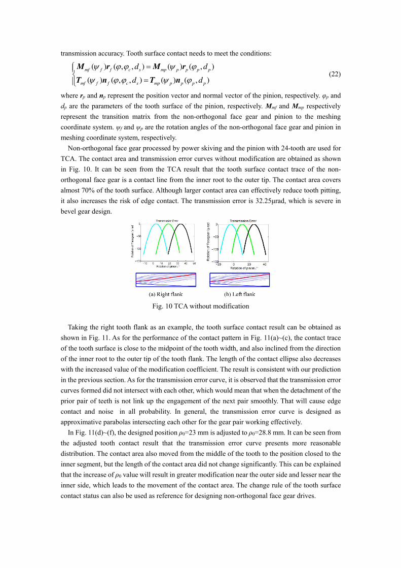
Non-orthogonal face gear processed by power skiving and the pinion with 24-tooth are used for TCA. The contact area and transmission error curves without modification are obtained as shown in Fig. 10. It can be seen from the TCA result that the tooth surface contact trace of the non-orthogonal face gear is a contact line from the inner root to the outer tip. The contact area covers almost 70% of the tooth surface. Although larger contact area can effectively reduce tooth pitting, it also increases the risk of edge contact. The transmission error is 32.25μrad, which is severe in bevel gear design.
Fig. 10 TCA without modification
Taking the right tooth flank as an example, the tooth surface contact result can be obtained as shown in Fig. 11. As for the performance of the contact pattern in Fig. 11(a)~(c), the contact trace of the tooth surface is close to the midpoint of the tooth width, and also inclined from the direction of the inner root to the outer tip of the tooth flank. The length of the contact ellipse also decreases with the increased value of the modification coefficient. The result is consistent with our prediction in the previous section. As for the transmission error curve, it is observed that the transmission error curves formed did not intersect with each other, which would mean that when the detachment of the prior pair of teeth is not link up the engagement of the next pair smoothly. That will cause edge contact and noise in all probability. In general, the transmission error curve is designed as approximative parabolas intersecting each other for the gear pair working effectively.
In Fig. 11(d)~(f), the designed position ρ0=23 mm is adjusted to ρ0=28.8 mm. It can be seen from the adjusted tooth contact result that the transmission error curve presents more reasonable distribution. The contact area also moved from the middle of the tooth to the position closed to the inner segment, but the length of the contact area did not change significantly. This can be explained that the increase of ρ0 value will result in greater modification near the outer side and lesser near the inner side, which leads to the movement of the contact area. The change rule of the tooth surface contact status can also be used as reference for designing non-orthogonal face gear drives.
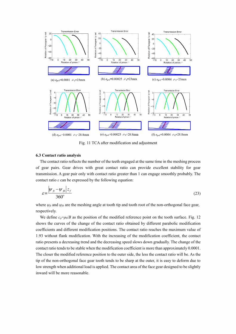
Fig. 11 TCA after modification and adjustment
6.3 Contact ratio analysis
The contact ratio reflects the number of the teeth engaged at the same time in the meshing process of gear pairs. Gear drives with great contact ratio can provide excellent stability for gear transmission. A gear pair only with contact ratio greater than 1 can engage smoothly probably. The contact ratio ε can be expressed by the following equation:
=360
ft fb fz
o
(23)
where ψft and ψfb are the meshing angle at tooth tip and tooth root of the non-orthogonal face gear, respectively.
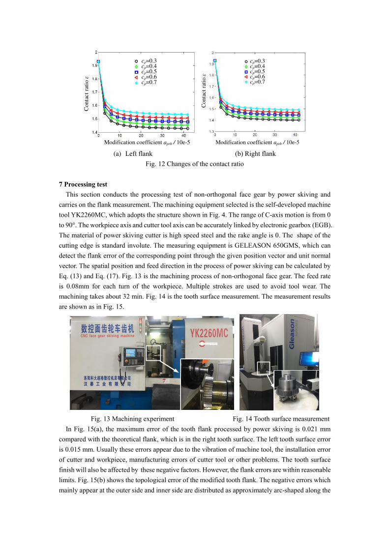
We define cρ=ρ0/B as the position of the modified reference point on the tooth surface. Fig. 12 shows the curves of the change of the contact ratio obtained by different parabolic modification coefficients and different modification positions. The contact ratio reaches the maximum value of 1.93 without flank modification. With the increasing of the modification coefficient, the contact ratio presents a decreasing trend and the decreasing speed slows down gradually. The change of the contact ratio tends to be stable when the modification coefficient is more than approximately 0.0001. The closer the modified reference position to the outer side, the less the contact ratio will be. As the tip of the non-orthogonal face gear tooth tends to be sharp at the outer, it is easy to deform due to low strength when additional load is applied. The contact area of the face gear designed to be slightly inward will be more reasonable.
Modification coefficient aprb / 10e-5
Conta
ct
rati
o ε
cρ=0.3cρ=0.4cρ=0.5cρ=0.6cρ=0.7
cρ=0.3cρ=0.4cρ=0.5cρ=0.6cρ=0.7
Modification coefficient aprb / 10e-5
Conta
ct
rati
o ε
(a) Left flank (b) Right flank
Fig. 12 Changes of the contact ratio
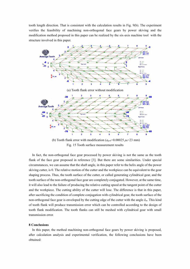
7 Processing test This section conducts the processing test of non-orthogonal face gear by power skiving and
carries on the flank measurement. The machining equipment selected is the self-developed machine tool YK2260MC, which adopts the structure shown in Fig. 4. The range of C-axis motion is from 0 to 90°. The workpiece axis and cutter tool axis can be accurately linked by electronic gearbox (EGB). The material of power skiving cutter is high speed steel and the rake angle is 0. The shape of the cutting edge is standard involute. The measuring equipment is GELEASON 650GMS, which can detect the flank error of the corresponding point through the given position vector and unit normal vector. The spatial position and feed direction in the process of power skiving can be calculated by Eq. (13) and Eq. (17). Fig. 13 is the machining process of non-orthogonal face gear. The feed rate is 0.08mm for each turn of the workpiece. Multiple strokes are used to avoid tool wear. The machining takes about 32 min. Fig. 14 is the tooth surface measurement. The measurement results are shown as in Fig. 15.
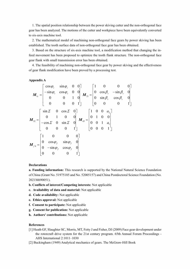
Fig. 13 Machining experiment Fig. 14 Tooth surface measurement In Fig. 15(a), the maximum error of the tooth flank processed by power skiving is 0.021 mm
compared with the theoretical flank, which is in the right tooth surface. The left tooth surface error is 0.015 mm. Usually these errors appear due to the vibration of machine tool, the installation error of cutter and workpiece, manufacturing errors of cutter tool or other problems. The tooth surface finish will also be affected by these negative factors. However, the flank errors are within reasonable limits. Fig. 15(b) shows the topological error of the modified tooth flank. The negative errors which mainly appear at the outer side and inner side are distributed as approximately arc-shaped along the
tooth length direction. That is consistent with the calculation results in Fig. 9(b). The experiment verifies the feasibility of machining non-orthogonal face gears by power skiving and the modification method proposed in this paper can be realized by the six-axis machine tool with the structure involved in this paper.
(a) Tooth flank error without modification
(b) Tooth flank error with modification (aprb=0.00025 ρ0=23 mm) Fig. 15 Tooth surface measurement results
In fact, the non-orthogonal face gear processed by power skiving is not the same as the tooth flank of the face gear proposed in reference [3]. But there are some similarities. Under special circumstances, we can assume that the shaft angle, in this paper refer to the helix angle of the power skiving cutter, is 0. The relative motion of the cutter and the workpiece can be equivalent to the gear shaping process. Thus, the tooth surface of the cutter, or called generating cylindrical gear, and the tooth surface of the non-orthogonal face gear are completely conjugated. However, at the same time, it will also lead to the failure of producing the relative cutting speed at the tangent point of the cutter and the workpiece. The cutting ability of the cutter will lose. The difference is that in this paper, after sacrificing the condition of complete conjugation with cylindrical gear, the tooth surface of the non-orthogonal face gear is enveloped by the cutting edge of the cutter with the angle δm. This kind of tooth flank will produce transmission error which can be controlled according to the design of tooth flank modification. The tooth flanks can still be meshed with cylindrical gear with small transmission error.
8 Conclusions
In this paper, the method machining non-orthogonal face gears by power skiving is proposed, after calculation analysis and experimental verification, the following conclusions have been obtained:
1. The spatial position relationship between the power skiving cutter and the non-orthogonal face gear has been analyzed. The motions of the cutter and workpiece have been equivalently converted to six-axis machine tool.
2. The mathematical model of machining non-orthogonal face gears by power skiving has been established. The tooth surface data of non-orthogonal face gear has been obtained.
3. Based on the structure of six-axis machine tool, a modification method that changing the in-feed movement has been proposed to optimize the tooth flank structure. The non-orthogonal face gear flank with small transmission error has been obtained.
4. The feasibility of machining non-orthogonal face gear by power skiving and the effectiveness of gear flank modification have been proved by a processing test.
Appendix A
1
cos sin 0 0
sin cos 0 0
0 0 1 0
0 0 0 1
c c
c c
c
M 21
1 0 0 0
0 cos sin 0
0 sin cos 0
0 0 0 1
c c
c c
M
32
sin 0 cos 0
0 1 0 0
cos 0 sin 0
0 0 0 1
M
2
43
1
1 0 0
0 1 0 0
0 0 1
0 0 0 1
a
a
M
4
1 0 0 0
0 cos sin 0
0 sin cos 0
0 0 0 1
f f
f
f f
M
Declarations
a. Funding information: This research is supported by the National Natural Science Foundation of China (Grant No. 51975185 and No. 52005157) and China Postdoctoral Science Foundation (No. 2021M690051). b. Conflicts of interest/Competing interests: Not applicable
c. Availability of data and material: Not applicable
d. Code availability: Not applicable
e. Ethics approval: Not applicable
f. Consent to participate: Not applicable
g. Consent for publication: Not applicable
h. Authors' contributions: Not applicable
References
[1] Heath GF, Slaughter SC, Morris, MT, Fetty J and Fisher, DJ (2009) Face gear development under the rotorcraft drive system for the 21st century program. 65th Annual Forum Proceedings - AHS International 2:1011–1030
[2] Buckingham (1949) Analytical mechanics of gears. The McGraw-Hill Book
[3] Litvin FL, Zhang Y. and Wang JC (1992a) Design and geometry of face-gear drives, Journal of Mechanical Design. Transactions of the ASME 114(4):642-647
[4] Litvin FL, Wang J, Bossler RB, Chen, YD, Heath G and Lewicki, DG (1992b) Application of Face-Gear Drives in Helicopter Transmissions. Journal of Mechanical Design, Transactions of the ASME 116(3):672-676
[5] Litvin FL, Egelja A, Tan J and Heath G (1998) Computerized design, generation and simulation of meshing of orthogonal offset face-gear drive with a spur involute pinion with localized bearing contact. Mechanism and Machine Theory 33(1-2):87-102
[6] Litvin FL and Fuentes A (2004) Gear Geometry and Applied Theory. Cambridge University Press
[7] Wang Y, Hou L, Lan Z and Zhang G (2016) Precision grinding technology for complex surface of aero face-gear. International Journal of Advanced Manufacturing Technology 86(5-8):1263-1272
[8] Wang Y, Lan Z, Hou L, Chu X and Yin Y (2017) An efficient honing method for face gear with tooth profile modification. International Journal of Advanced Manufacturing Technology 90(1-4):1155-1163
[9] Chu X, Wang Y, Du S, Huang Y and Su G (2020) An efficient generation grinding method for spur face gear along contact trace using disk CBN wheel. International Journal of Advanced Manufacturing Technology 110(5-6):1179-1187
[10] Kawasaki K, Tsuji I and Gunbara, H (2018) Geometric design of a face gear drive with a helical pinion. Journal of Mechanical Science and Technology 32(4):1653-1659
[11] Kin'ichi S, Masafumi S and Md.Rezaur R (1978) Development of a New Type Cutter "Revolving Type Pinion Cutter" for the Hobbing of the Face Gear. Bull JSME 21(155):899-906
[12] Hermann J (2011) CONIFACE Face Gear Cutting and Grinding. American Gear Manufacturers Association Fall Technical Meeting :1-14
[13] Von Pittler W (1910) Verfahren zum Schneiden von Zahnrädern mittels eines zahnradartigen, an den Stirnflächen der Zähne mit Schneidkanten versehenen Schneidwerkzeugs, Deutsche Patentschrift Nr. 243514.
[14] Guo E, Hong R, Huang X and Fang C (2014) Research on the design of skiving tool for machining involute gears. Journal of Mechanical Science and Technology 28(12):5107-5115
[15] Guo E, Hong R, Huang X and Fang C (2015) Research on the cutting mechanism of cylindrical gear power skiving. International Journal of Advanced Manufacturing Technology 79(1-4):541-550
[16] Spath D and Hühsam A (2002) Skiving for high-performance machining of periodic structures. CIRP Annals - Manufacturing Technology 51(1):91-94
Related Documents