-A166 029 INTEGRATED BATTLEFIELD EFFECTS RESEARCH FOR THE NATIONAL TRAINING CENTER.. (U) SCIENCE APPLICATIONS INTERNATIONAL CORP LA JOLLA CA D ERICKSON ET AL. CLRSSIFIED 31 DEC 84 SRIC-R-LJF-84-019-RPP-1 F/G 5/9 U" II

Welcome message from author
This document is posted to help you gain knowledge. Please leave a comment to let me know what you think about it! Share it to your friends and learn new things together.
Transcript

-A166 029 INTEGRATED BATTLEFIELD EFFECTS RESEARCH FOR THENATIONAL TRAINING CENTER.. (U) SCIENCE APPLICATIONSINTERNATIONAL CORP LA JOLLA CA D ERICKSON ET AL.
CLRSSIFIED 31 DEC 84 SRIC-R-LJF-84-019-RPP-1 F/G 5/9 U"
II

1.0
II IfL2i5
-I~cP REC1TO L T( R

AD-A 166 029 DNA-TR-85-13-AP-l
INTEGRATED BATTLEFIELD EFFECTS RESEARCH FOR THENATIONAL TRAINING CENTERAppendix I-Feasibility Study of Transferring ARTBASS Code from a .
Perkin-Elmer/Lexidata System to a VAX/De Anza System
Science Applications International CorporationP. 0. Box 2351La Jolla, CA 92038-235 1
31 December 1984
Technical Report
CONTRACT No. DNA 001-81-C-0273
distribution is unlimited.
THIS WORK WAS SPONSORED BY THE DEFENSE NUCLEAR AGENCYUNDER RDT&E RMSS CODE S400082466 V99QAXNLOO125 H2590D. W. 7,
Prepared for IlDq6Director
___ DEFENSE NUCLEAR AGENCYWashington, DC 20305- 1000 B3
C7-1

UNCLASSIFIED
REPORT DOCUMENTATION PAGEa QEOz 0 C..aSS,;CA CN ' ;ESR C VE 'ARK %GS
UNCLASSIFIED "__ _ _-:'__ _ _2E.R17 C_.ASSFcw A .,OIr 3 DIS ' N.oF~~F
N/A since Unclassified Approved for public release; distribution -?.-
Zb :EC._ASP-C7ON, DOWNFGAD,NG SCHEOLE is unlimited.N/A since Unclassified "-"-_"""_.".-_-....
4 -ERFO'RMING ORGANIZArON REPORT NLMBER(S) S MONITORING ORGANIZA7ON 4EPCRT NL.MS-(S)
R :LJF-84-019 DNA-TR-35-13-AP- I
6a NAME OF PERFORMING ORGANIZATiON 6o OFF;C SYMBOL 7a NAME OF MONITORING ORGXNiZA7CNScience Applications (if aoIicaalo) DirectorInternational Corporation Defense Nuclear Agency
ic. .10DRESS Cry Stare nd ZIPCode) 'b ADDRESS Cry, State. ano ZIP Code)
P.O. Box 2351La0 ola C92038 2Washington, DC 20305-1000 OLa Jolla, CA 92038-2351
Sa NAME OF :-NING. SPONSORING 8b OF;'C: SYMBOL 3 PROCREMEN" NSTRUMEN OENTFCA' ON %LM ERORGANIZA 7ON (If 4aodrcabIe)
DNA 001-81-C-0273
Sc- ADORESS (Cty, State. and ZIP Code) 'Q SOURCE OF ;F,,NNG NUNMBE2S
PROG.RAM PROEC- -ASK VGKELEMENT NO NO 40 AC=:-SScN NC
62715H V99QAXN L DH065313-i.E Includf Security Clawhfcation)INTEGRATED BATTLEFIELD EFFECTS RESEARCH FOR THE NATIONAL TRAINING CENTERAppendix I-Feasibility Study of Transferring ARTBASS Code from a Perkin-Elmer/Lexidata
12 PERSONAL Akr.4O(S)Erickson, 0.; lckler, J.; McKeown, P.; Metzger, L.; Plock, R.; Packard, B.; and Birney, J.
13a "V0 E OF RE1ORT 13b TIME COVERED '4 0ATE OF REPCR Year Mont, Day) S -'AGE COL,N.-
Technical c=om 830613 'o 841230 841231 8816 Sw.POLEMENTARY NOTATIONThis work was sponsored by the Defense Nuclear Agency under RDT&E RMSS Code, S400082466V99QAXNLO125 H25900.
7 COSA7! CODES 'S S.BSEC- "ERMS Coninue on reverse .t mecessaiy anal n oentrfy by O cIr uimber)OI ROP SB.GROUP Training Military Doctrine
1 9 Integrated Battlefieldi5 1 7 1 Military Strategy
9 A S-RAC- Continue on 'everte ,f necelsary and dentify by 0lo<X number)
Research performed to evaluate and develop enhancements for integrated battlefield trainingat the U.S. Army National Training Center is described. These enhancements had been identi-fied and concepts developed for their application in earlier phases of this research. Thereport consists of the basic volume summarizing the research tasks, approach, results, con-clusions, and recommendations; plus twelve appendices which provide details on the ninemajor tasks into which the research was divided. Research performed and the associatedappendices are as follows:
Development of nuclear and chemical environmental and effects software:Analysis of nuclear algorithms Appendix ARequirements specification for nuclear and chemical model algorithms
at the NTC Appendix BChemical model algorithm description Appendix C
ZSQ 5 8U7'ON AdALABIL~rY OF AEISTRAC7 _ RCSCR ASS,p CA 7 ON
C2 NC'ASSF ,: 'I ,NLM,.D M SAME AS tP 2 rc .SERS UNCLASSIFIED'Za N4AME OF RESONSBLE NO'VIDUAL 7Eb EP ONE (incluae A3rea C,.e) '-' 0"C: S'%13CLBetty L. Fox (202) 325-7042 . DNA/STTI
00 FORM 1473,34 MAR 13 APR eton mav oe sea vi erawsteo SEC_." C-ASS,, CA ' F -a - ":All Ot @, ea,! OP*s are oosoie , .-. " -.~I t~'e~O'~ io UNCLASSIFIED
................... ... .. -...... . . .......-.

UNCLASSIFIED
SECURITY CLASSIFCATION OF THIS PAGE
11. TITLE (Continued)
System to a VAX/De Anza System
19. ABSTRACT (Continued)
Demonstration of the system for combining live and notional battalions for training higher Owl.level staffs in integrated battlefield (IB) command and control:
Functional requirements analysis for IB command and control simulation Appendix DReport on the demonstration Appendix E
Analysis and design of field simulators for nuclear and chemical warfare:Technical and operational impacts of field simulators Appendix F (Capability of off-the-shelf paging system to communicate at Ft. Irwin Appendix GDesigns of field simulators Appendix H
Adaptation of nuclear and chemical software to other Army training models:Feasibility of transferring ARTBASS Code from Perkin-Elmer to VAX Appendix IDivision/Corps training simulation functional analysis Appendix JARTBASS conversion to VAX Appendix KRequirements specification for adding nuclear and chemical models
to ARTBASS Appendix L
This research provided the following products:Software which models nuclear and chemical environment and effects with appropriatefidelity and timing for training and which is ready for installation on NTC computers.
A demonstrated capability for combining actions of real battalions with computersimulated notional battalions for training brigade/division commanders and staffs.
An analysis of the impacts of using field simulators at the NTC for nuclear andchemical warfare training, and the designs of the selected simulators (i.e.,common control system, radiacmeters, dosimeters, chemical detectors).
Analysis of the application of nuclear and chemical models to other Army battaliontraining models; conversion of the ARTBASS model to operate on the VAX 11/780;incorporation of the nuclear and chemical models into ARTBASS; and demonstrationof the nuclear and chemical models using ARTBASS.
UNCLASSIFIEDSECURITY CLASSIPICATION OP THIS PAGE
r °.'.

CONVERSION FACTORS FOR U.S. CUSTOMARY TO METRIC (SI)UNITS OF MEASUREMENT
To Convert From To Multiply ay
angstrom Meers (m [.000 000 x E -10 .
atmosphere (normal) Kilo pascal (kPa) 1.013 25 X E -2
bar kilo pascal (kPa) 1.000 000 X E +2
bMen tcer2
(m2) 1.000 000 X E -28
British thermal unit (thetmochemical) Joule (J) 1.054 350 X E -3
zal (thermochemicsi)'ca meta ouLem" (J/n,) ..184 000 X E2 -2calorie (thermochemical) )oule (J) 4.184 300
calorie (chermOchemLcal)/g 2oule per kilogram (J/kg) 4.184 000 X E -3
curie giga becquerel (Cbq) 3.700 000 K E -1
degree Celsius degree kelvin (K) t V C .173.15
degree (angle) radian (tad) 1.745 329 X E -zdegree Farettheit degree kelvin (K) Wt " F + 459.67)/
1.8
electron volt joule (J) 1.602 19 X E -19
ert joule (J 1.000 000 X E -7
erg/second -act (W) 1.000 000 X E -,
foot meter (m) 3.048 000 K E -1
foot-pound-force joule (J 1.355 818
gallon (U.S. liquid) meter (m 3.785 412 K E -3
inch meter m) 2.540 000 X E -2
jerk joule (J) 1.000 000 X E -9
joule kilogram (1/kg) (radiationdose absorbed) gray (Gy)* 1.000 000
kilotona terajoules 4.183
kip (1000 lbf) newton (N) 4.448 222 K E -3
kip/inch2
(ksi) kilo pascal (kPa) 6.894 757 X E -3
ktap newton-secondim (N-S/m") 1.000 000 X E -2
micron meter (m) 1.000 000 X E -6
mlI meter (m) 2.540 000 K E -5
ile (interoational) meter (m) 1.609 344 X E .3
ounce kilogram (kg) 2.834 952 K E -2
pound-force (lbf avoirdupois) newton (8) ..48 22-2
pound-force inch newton-meter (4n-) 1.129 348 K E --
pound-force/inch newcon/meter (S/m) 1.751 268 X E -2
pound-force/foot2
kilo pascal (kPa) 4.788 026 x E -E
pound-force/inch2
(psi) klo pascal (kEa) 6.894 '57
pound-mae (Ibm avoirdupois) 'Kilogram tk%) -. 535 924- < E
pound-mass-fooC (moment of inertia) kilogram-meter kg-' ) -.21. 211 12 -X
pound-mass/foot3
kilogram-meter3 (kg m .361 - x E -i
red (radiation dose absorbed gray (Gv)* 1.300 300 x -:
roentgeo. coulomb/kilogram (Ckg) . 60 I -- -
shako second (s) 1.000 300 x E -
s hg kilogram kkg) ;..59 3Q0 E-
torr (lqw Hg, 3" C) kilo 2ascal (kP3) 1.33 E -i
*The gray (Gy) is the accepted SI unit equivalent to the ener,>' impartec
by ionizing radiation to a mass and corresponds to one joule kilogram.
The becquerel (3q) is the SI unit of radioactivity, I Bc = event s.
iii
iV

..
TABLE OF CONTENTS
Section Page
CONVERSION TABLE .... ................ ....3..
1 INTRODUCTION . .I................ 1
2 CONSIDERATIONS FOR THE TRANSFER OFARTBASS-M CODE . . . . . . . . . . . . . . . . . 5
2.1 HARDWARE .. . .. . .. . .. .
2.1 .A2.1R Construts . . . .9
2.1.1 Perkin-Elmer (Model 3240) .. .. 02.1.2 VAX 11/780 .......... 62.1.3 Hardware Assessment .... * 8
2.2 FORTRAN. o o 8
2.2.1 Constructs ....... 9
2.2.1.1 Perkin-Elmer . . . . . . o o 10
2.2.1.2 VAX 11/780 . . . . . o o o 10
2.2.2 Intrinsic Functions. ........... 10
2.2.2.1 Perkin-Elmer . .. .. .. . 122.2.2.2 VAX 11/780 . . . o o ... .. 12
2.2.3 Data Manipulation Functions ...... 12
2.2.3.1 Perkin-Elmer . . . . .. .. 172.2.3.2 VAX 11/780 o . . .. .. . . . 17
2.2.4 Character Manipulation Functions . . . . 17
2.2.4.1 Perkin-Elmer . o . . . o . . . 202.2.4.2 VAX 11/780 . . o . o o o o 20
2.2.5 Language Extensions . . . ....... 20
2.2.5.1 Perkin-Elmer . . . . . . . . . 212.2.5.2 VAX 11/780 . . . . . . . . . . 21 "
2.2.6 Input/Output Functions . . . . . . . . . 22
2.2.6.1 Perkin-Elmer . . . . . . . . . 22
2.2.6.2 VAX 11/780 . . . . . . . . . 22
. . . *.-

TABLE OF CONTENTS (Continued)
Section Page
2.2.7 Assessment .......... .... 23
2.2.7.1 Constructs * . . 232.2.7.2 Instrinsic Functions ..... 232.2.7.3 Data Manipulation Functions *23
2.2.7.4 Character Manipulation Func-tions. . . .... 23
2.2.7.5 Language Exensions ..... 232.2.7.6 Input/Output Functions . . . . 23 -
2.3 ASSEMBLY/MACHINE LANGUAGE . . . . . . . . . . . . 23
2.3.1 Perkin-Elmer ...... . .24
2.3.2 VAX 11/780 . . . . . . . . . . . . . . . 242.3.3 Assessment . . . . . . . . . . . . . . . 24
2.4 INPUT/OUJTPUT . . . . . . . . . . . . . . . . . . 24
2.4.1 File Management. . 25
2.4.1.1 Perkin-Elmer . . . . 25
2.4.1.2 VAX 11/780 ... . . . . . . . . 25
2.4.2 File Organization . 25
2.4.2.1 Perkin-Elmer . . . . . . . . . 262.4.2.2 VAX 11/780 . . . . . . . . . . 28
2.4.3 Assessment . . . . . . . . . . . . . . . 28
2.5 EXECUTION . . . . . . . . . . . . . . . . . . . 28
2.5.1 Perkin-Elmer ..... 28
2.5.1.1 Overlays ... 282.5.1.2 Task and Process Development .29
2.5.1.3 Task Communication . 30 -
2.5.2 VAX 11/780 . . . . . . . . . . . . . . . 30
2.5.2.1 Overlays ... 302.5.2.2 Task and Process Development .30
2.5.2.3 Task Communication . . . . . . 30

7,~ -W. . -
TABLE OF CONTENTS (Continued)
Section Page
2.5.3 Assessment ............... 32
2.5.3.1 Overlays .......... 32I 2.5.3.2 Task and Process Development. 322.5.3.3 Task Communication . . . . . . 32
2.6 COMMAND LANGUAGE ................ 35
2.6.1 Perkin-Elmer ......... . . 352.6.2 VAX 11/780 . . . . . . . . . . . . . . . 362.6.3 Assessment . .. ...... .... .. 37
2.7 CODE UNIFICATION . . . . . . . . . . . . . . . . 37
2.7.1 Data Manipulation Functions . . . . . . 382.7.2 Character Manipulation Functions . . . . 392.7.3 Task Communication .. .. .. .. .. . 39
3 ARTBASS-M CODE TRANSFER PROCEDURES . . . . . . . 41
3.1 FORTRAN TRANSFER. . . . . .. . . . . . . . . . 41
3.1.1 Perkin-Elmer to VAX 11/780 . . . . . . . 423.1.2 VAX 11/780 . . . . . . . . . . . . . . . 42
3.2 ASSEMBLY LANGUAGE TRANSFER. . . . . . . . . . . 42
3.2.1 Perkin-Elmer to VAX 11/780 . . . . . . . 42U 3.2.2 VAX 11/780 to Perkin-Elmer . 43
3.3 SYSTEM UTILITY TRANSFER . . . . . . . . . . . . 43
3.3.1 Perkin-Elmer to VAX 11/780 . . . . . . . 433.3.2 VAX 11/780 to Perkin-Elmer ....... 43 5
3.4 SCENARIO DATA BASE PROCESSING . . . . . . . . . 43
3.4.1 Perkin-Elmer to VAX 11/780 . . . . . . . 43 .-
3.4.2 VAX 11/780 to Perkin-Elmer . . . . . . . 43
3.5 INPUT/OUTPUT TRANSFER. . . . . . . . . . . . . . 43
3.5.1 Perkin-Elmer to VAX 11/780 . . . . . . . 443.5.2 VAX 11/780 to Perkin-Elmer . . . . . . . 44
Vi- , .

mill
TABLE OF CONTENTS (Continued)
Section Page
3.6 FRONT-END INTERFACE .............. 44
3.6.1 Perkin-Elmer to VAX 11/780 . . . . . . . 44
3.6.2 VAX 11/780 to Perkin-Elmer . . . . . . . 44
3.7 JOB INITIATDN AND CONTRL . . . . . . . . . . . 44
3.7.1 Perkin-Elmer to VAX 11/780 . . . . . . . 443.7.2 VAX 11/780 to Perkin-Elmer . . . . . . . 45
4 FRONT-EACC .T R.E... .......... .. 46
4.1 INTRODUJCTION . . . . . . . . . . . . . . . . . . 46
4.2 HARDWARE . . . . . . . . . . . . . . . . . . . . 46
4.2.1 CATTS . . . . . . . . . . . . . . . . 464.2.2 ARTBASS-M . . . . . . . . . . . . . . . 474.2.3 NTC Test Support Driver . . . . . . . . 474.2.4 Mace . . . . . . . . . . . . . 504.2.5 Hardware Assessment ... 50
4.3 SIMULATION CONTROL . . . . . . . . . . . . . . . 53
4.3.1 CATIS . . . . . . . . . . . . . . . . 534.3.2 ARTBASS-M . . . . . . . . . . . . . . . 564.3.3 NTC Test Support Driver . . . . . . . . 564.3.4 Mace . . . . . . . . . . . . . 574.3.5 Simulation Control Assessment ..... 57
4.4 MAP DISPLAY . . . . . . . . . . . . . . . . . . 57
4.4.1 CATTS . . . . . . . . . . . . . . . . . 7 574.4.2 ARTBASS-M . . . . . . . . . . . . . . . 584.4.3 NTC Test Support Driver . . . . . . . . 584.4.4 Mace . . . . . . . . . . . . . . . . . . 594.4.5 Map Display Assessment . . . . ..... 59
4.5 TACTICAL/OPERATIONAL MENUS . . . . . . . . . . . 59
4.5.1 CATTS . . . . . . . . . . . . . . . . . 604.5.2 ARTBASS-M ........ 604.5.3 NTC Test Support Driver ........ 614.5.4 Mace . . . . . . . . . . . . . . . . . 624.5.5 Menu Assessment ............ 62
vii

TABLE OF CONTENTS (Concluded)
wr
Section Page
4.6 SYMBOLOGY . . . . . . . . . . . . . . . . . . . 63
4.6.1 CATTS . . . . . . . . . . . . . . . 63 -
4.6.2 ARTBASS-M . . . . . . . . . . . . . . . 644.6.3 NTC Test Support Driver ........ 654.6.4 Mace . . . . . . . . . . . . . . . . . . 664.6.5 Symbology Assessment . . ........ 66
4.7 SIDE PANEL DISPLAYS . . . . . . . . . . . . . . 66
4.7.1 CATTS e . . . * * .. . . . . .. . . . 674.7.2 ARTBASS-M . . . * 9 . , 9 e .. .. . 674.7.3 NTC Test Support Driver . . . . . . . . 674.7.4 Mace . 0 0 0 a . .. . . . . . . . . . . 674.7.5 Side Panel Assessment . . . . . . . . . 67
4.8 ALPHANUMERIC DISPLAYS . . . . . . . . . . . . . 68
4.8.1 CATST . . . . . . . . . . . . . . . . . 68
4.8.1.1 Unit Special Status Report . . 684.8.1.2 Log/Admin Status Report . . . 684.8.1.3 Tactical Alerts . . . . . . . 684.8.1.4 Interactor Alerts . . . . . . 69
4.8.2 ARTBASS-M . . . . .. . ... . .. 69
4.8.2.1 Unit Special Status Report . . 694.8.2.2 Log/Admin Status Report . . . 704.8.2.3 Tactical Alerts ....... 704.8.2.4 Interactor Alerts ...... 70
4.8.3 NTC Test Support Driver ........ 70
4.8.3.1 Unit Special Status Report . . 704.8.3.2 Log/Admin Status Report . . . 714.8.3.3 Tactical Alerts . . . . . . . 714.8.3.4 Interactor Alerts . . . . . . 71
4.8.4 Mace . . . . . . . . . . . . . . . . . . 71
4.8.4.1 Unit Special Status Report 71 '
4.8.4.2 Log/Admin Status Report . . . 724.8.4.3 Tactical Alerts . . . . . . . 724.8.4.4 Interactor Alerts . . . . . . 72 U!-
4.8.5 Alphanumeric Display Assessment . . . . 72
Viii ii
I• .]-
r * * te-..
- - .-.---r-.--.- i--.
• .W- .
LIST OF ILLUSTRATIONS
Figure Page
1 SYNOPSIS OF STUDY FINDINGS BY SECTION . • 3
2 ELEMENTARY INTRINSIC FUNCTIONS . . . . . 133 MIN AND MAX INTRINSIC FUNCTIONS . . . . . 144 TYPE CONVERSION INTRINSIC FUNCTIONS . . . 15
5 MISCELLANEOUS INTRINSIC FUNCTIONS . . . . 166 DATA MANIPULATION FUNCTIONS . . . . . . . 187 CHARACTER MANIPULATION FUNCTIONS . . . . 19 O08 AVAILABLE I/O STATEMENTS 27
9 ACCESS MODES FOR EACH FILE O1GANiZATION . 2710 VAX COMMUNICATION, SYNCHRONIZATION, AND
SHARING FEATURES . . . . . . . . . . . 3111 PERKIN-ELMER TASK AND PROCESS DEVELOPMENT
COMMAND FILE . . . . . . . . . . . . 3312 VAX TASK AND PROCESS DEVELOPMENT COMMAND
FILE . . . . . . . . . . . . . . . . 34
13 CATTS EQUIPMENT CONNECTION . . . . . . . 4814 ARTBASS-M EQUIPMENT CONNECTION . . . . . 4915 TEST SUPPORT DRIVER EQUIPMENT CONNECTION. 5116 MACE EQUIPMENT CONNECTION . . . . . . . . 5217 VAX/DE ANZA ARTBASS . . . . . . . . . . 54 " " ...
18 VAX/LEXIDATA ARTBASS . . . . . . . . . . 55
DIAL
cc, t\,
ix I"

wo "
L
SECTION 1
INTRODUCT ION
The purpose of this document is to delineate those itemsinvolved in the creation of an ARTBASS-M development systemwhich will be based on a VAX 11/780 system. This includesthe followingitems: OIL
1. The physical transfer of ARTBASS-M code currentlyresident on the Perkin-Elmer system to a permanentdevelopment system based on the VAX 11/780.
2. The conversion of Perkin-Elmer based FORTRAN 77code to VAX FORTRAN 77.
3. The implementation of the working ARTBASS-M systemon the VAX.
4. The subsequent transfer of the working VAXARTBASS-M code back to the Perkin-Elmer system.
5. The installation and implementation of the workingARTBASS-M system on the Perkin-Elmer system.
Each of these aspects will be discussed in the following k.sections.
In order to fully understand the ensuing discussion, theunderlying assumptions of this study should be enumerated.They are the following:
1. There will be no modifications to the ARTBASS-Mcode that currently exists on the Perkin-Elmersystem.
2. Only those lines of code that do not or cannotexecute on the VAX system will be altered to makethe Perkin-Elmer ARTBASS-M code resident on the VAXsystem.
3. The resultant VAX code will be developed such that
it will execute on the Perkin-Elmer system as well.
4. The VAX system will be considered as the resident I
ARTBASS-M development system.
As in almost any study involving the relocation of existingcode from one computer system to another, certain areas ofcommonality are noticed. To facilitate and reduce the
1
V[

differences in support code and to enhance systemmaintainability and configuration control, a list of futureoptions that will further unify the support code on both Fsystems will be noted.
An overview of the findings of this study is presented inthe following figure (Figure 1). At the time of this study, -[the standards and conventions used to implement ARTBASS-M onthe PERKIN-ELMER computer system are not known. Certain of p.the findings of this study may not apply to the actualconversion situation. For example, assembly language maynot actually be present on ARTBASS-M, so rewriting that codemay not be necessary.
2
'.r

~---o" " +
MA
SECTION/SUBJECT SYNOPSIS OF FINDINGS -*--------------------------------+------------------------------------------------
I FORTRAN: 'I Constructs I No major difficulties. "
Intrinsic functions I No expected problems.
I Data manipulation I Underlying code rewritten; Ifunctions I minimal problems.
I Character manipulation I Underlying code rewritten; 'I functions I minimal problems. .
Language extensions I User written utility required II to format at transfer time.
Input/Output functions I Underlying code rewritten; "I medium difficulty. .
+--------------------------------+------------------------------------------------1 ASSEMBLY LANGUAGE: I .
I All code rewritten; major "I undertaking; medium difficulty. I
+--------------------------------+------------------------------------------------I INPUT/OUTPUT: I II File management I Nontransferable; machineI I dependent. .
I File organization I No expected problems.------------------ +------------------------------------------------I EXECUTION:I Overlays I Not supported on VAX; medium I
I difficulty.
I Task and process I Nontransferable; machineI development I dependent; low difficulty. I
I Task communication I Most difficult part ofI I conversion; high difficulty. -+--------------------------------+------------------------------------------------I COMMAND LANGUAGE: , -iI Nontransferable; low I
I difficulty. I+--------------------------------+------------------------------------------------I CODE UNIFICATION: I
I New code; new capability; II I medium-to-high difficulty. I
-------------------------------------------------------------------
Figure 1. Synopsis of study findings by section.
3

- - - - - - - - - - - - - - - - - - - - - - - - - - - - - - - - - - --
ISECTION/SUBJECT I SYNOPSIS OF FINDINGS4-----r--------------------------4-------------------------------------------I TRANSFER PROCEDURES: II FORTRAN transfer I Perkin Elmer to VAX medium
II difficulty; VAX to Perkin Elmer II I low difficulty.I
I System utility I New code; medium difficulty. II transfer PEI
I Scenario data base I Single, one-way transfer;I processing I medium difficulty.I
I Input/Output transfer 1 I/0 capability same; lowI I difficulty.I
I Front-end interface I Interactive systemIII configuration dependent; high II I difficulty.
I Job initiation and I Nontransferable; lowII control I difficulty.I4-------------------------------.-------------------------------------------
I FRONT-END ARCHITECTURE:IIII Partial transferability; II I medium difficulty.I
4-----------------------------+-------------------------------------------------h
Figure 1. Synopsis of study findings by section(continued).
4

SECTION 2CONSIDERATIONS FOR THE TRANSFER OF ARTBASS-M CODE
2.1 HARDWARE.
•.-. o..
2.1.1 Perkin-Elmer (Model 3240).
The Perkin-Elmer 3240 is a 32-bit machine with a memorycapacity of 256,000 bytes to 16 million bytes. Themetal-oxide semiconductor (MOS) memory is installed in256,000 increments with a limit of four million bytes permemory bank.
The input/output devices attached to the computer areclassified according to their required speed. The slowerperipherals, such as printers, consoles and card readersinterface with the computer through the multiplexor bus.The bus can handle up to 1023 devices. The high speeddevices, such as disk and tape drives, interface through theDirect Memory Access (DMA) bus. Four DMA buses are Uavailable and each bus has eight ports.
The processor has a 8192 byte cache for fast processing ofinstructions and it has a user Writable Control Store of8192 bytes for fast execution of commonly used applicationutilities. A Floating Point Processor is available toincrease the processing speed of double-precision andfloating point instructions. The processor also providesthe capability of having one megabyte of shared memory,which can be shared by up to fourteen Central ProcessingUnits.
The instruction set in the Perkin-Elmer consists of thefollowing major functions:
1. Load/store halfwords, fullwords and multiple words
2. Fixed-Point arithmetic
3. Logical operations (AND, OR, Exclusive OR, Compareand Test)
4. Logical and arithmetic shifts and rotates
5. Bit string and bit manipulation
6. Floating-point arithmetic on single (32-bit) anddouble (64-bit) precision operands
5
. .

7. Status and control functions
8. List operations
9. Data handling operations
10. Input/output
11. Byte manipulations
12. Writable Control Store operations
13. Mixed floating-point transfers
14. Privileged system functions
15. Storage-to-storage instructions
16. Decimal conversion instructions
The Perkin-Elmer system provides the following software
languages:
1. CAL and CAL MACRO
2. FORTRAN VII .....
3. RPG II
4. RELIANCE
5. BASIC II
6. COBOL
2.1.2 VAX 11/780.
The Digital Equipment Corporation VAX 11/780 is a 32-bitmachine with a physical memory capacity of 256,000 bytes toeight million bytes. The computer has a virtual memorysystem, which allows a user to address up to four billionbytes of virtual address space. The MOS memory is installedin 256,000 byte increments.
The slower input/output devices, such as card readers,printers and consoles, interface through the UNIBUS. FourUNIBUS adapters can be installed in the computer and up tofifteen devices can be attached to each bus. The high speedinput/output devices, such as disk and tape drives,interface with the computer through the MASSBUS. FourMASSBUS adapters can be installed in the computer and up to -eight devices can be attached to each bus.
6
. . .. &Wild

The processor has a 8192 byte cache for fast processing ofinstructions and it has a user Writable Control store of 24kilobytes for fast execution of commonly used applicationutilities. A Floating-Point Accelerator is available toincrease th.e processing speed of double-precision andfloating-point instructions. The processor provides for oneto eight megabytes of memory that can be shared by more thanone Central Processing Unit.
The instruction set on the VAX 11/780 includes the followingmajor functions:
1. Integer and logical instructions
2. Floating-point instructions
3. Packed-decimal instructions
4. Character-string instructions
5. Bit-field instructions
6. Queue manipulation instructions
7. Address manipulation instructions
8. User-programmed general register control instruc-
tions
9. Branch, jump and case instructions
10. Subroutine call instructions
11. Procedure call instructions
Digital Equipment Corporation provides the following
software languages for the VAX 11/780:
1. MACRO assembler
2. FORTRAN
3. COBOL
4. BASIC
5. C
6. PL/I
7
. ....-.. .
•~~ " . . . . . . ..-. -°.,.• . . . .

7. PASCAL
8. CORAL 66
9. BLISS-32
2.1.3 Hardware Assessment.
The Perkin-Elmer 3240 and the VAX 11/780 are both 32-bitmachines with very similar architectures. The Perkin-Elmer -
has twice the memory capacity of the VAX; however, for thisapplication, eight megabytes of memory is more thansufficient. The VAX is a virtual memory system and thePerkin-Elmer is not; therefore, overlaying of subroutinesmight be required on the Perkin-Elmer.
Both computers have sufficient buses and ports to attach therequired peripherals. The instruction sets of the twocomputers provide the capabilities necessary to performintertask communications and bit, byte, floating pointsinstructions required by the math model and front-end. TheVAX 11/780 has more languages available than thePerkin-Elmer; however, both machines have FORTRAN andassembler which are required by the math model andfront-end.
The literature, provided by both vendors, indicates that thecomputing power of the Perkin-Elmer 3240 and the VAX 11/780is approximately equal.
2.2 FORTRAN.
Although FORTRAN is a higher-level language and is designedto be portable between machines, most computer 'manufacturershave taken some liberties with the implementation of thelanguage. However, most manufacturers market their systemsas having met FORTRAN 77 standards (American NationalStandard Programming Language FORTRAN, ANSI X3.9-1978). The
-'_. difficulty with meeting FORTRAN 77 standards though, is thatit merely specifies the form and establishes theinterpretation of programs expressed in the FORTRANlanguage. It does not dictate how to implement thelanguage.
The scope of FORTRAN 77 is very explicit. It includes the *- -
following items:
1. The form of a program written in the language.
2. Rules for interpreting the meaning of a program and
it's data.
8
. . .. . . . .. ... ... . - . . . , . ,, - , , • .- . . . . . ' .. .= . , ,: . ,

17.*i . . . . ... - --
3. The form of writing input data to be processed bythe program.
4. The form of the output data generated by theprogram.
The FORTRAN 77 standard does not specify the followingitems:
1. The mechanism by which programs are transformed foruse.
2. The method of program and data transcription to orfrom the data processing medium.
3. The operations required for setup and control ofthe use of programs on a system.
4. The results when the rules of the standard fail toestablish an interpretation.
5. The size or complexity of a program and its datathat exceeds the capacity or capability of asystem.
6. The range or precision of numeric quantities andthe method of result rounding.
7. The physical properties of input/output records,files, and units.
8. The physical properties and implementation ofstor age.
The FORTRAN 77 standard generally refers to permissibleforms and relationships for standard-conforming programsrather than for processors.
This section discusses those properties and conditions ofFORTRAN that usually effect the transfer of code betweencomputers. The main areas of consideration will concernFORTRAN constructs, intrinsic functions, data and charactermanipulation functions, any language extensions, andinput/output functions.
2.2.1 Constructs.
Constructs are the building blocks of programs. They definethe forms and relationships between well defined program -
units. They are designed to specify the syntax and ',interpretation of sets of instructions. This section dealswith the FORTRAN 77 constructs adopted by both systems.
9.".. . . .

2.2.1.1 Perkin-Elmer. The Perkin-Elmer series of 3200 and3400 machines are Ofully compliant with FORTRAN 770. Thismeans- that they have met the form and constructs of theFORTRAN 77 standard. They have, however, also developed and Uimplemented "language extensions" which augment the FORTRAN77 standard in ways which they believe will provide"increased programmer convenience" and enhance the usabilityof their machines.
2.2.1.2 VAX 11/780. The VAX 11/780 systems also meet theform and constructs of the FORTRAN 77 standard. They have,however, also developed and implemented "languageextensions' which augment the FORTRAN 77 standard in wayswhich they believe will provide increased programmerconvenience and enhance the usability of their machines.
2.2.2 Intrinsic Functions.
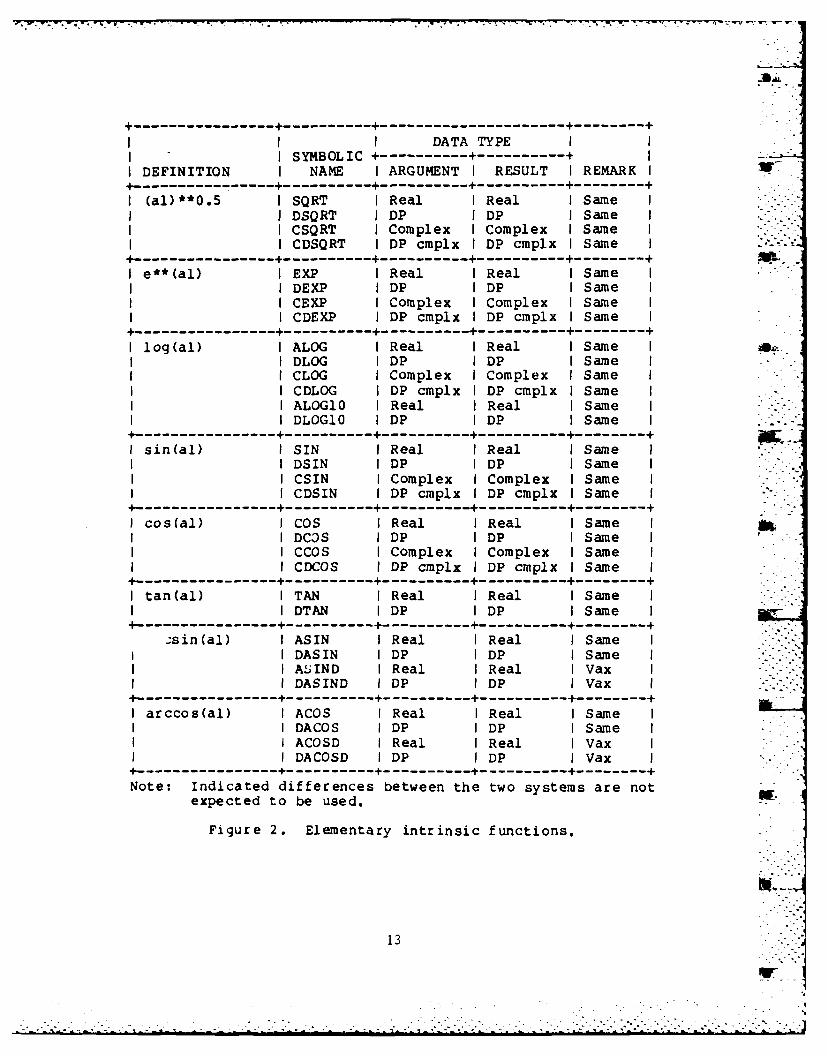
Intrinsic functions are functions which are availablethrough system libraries at compile time. These functionsinclude:
1. Elementary functions
Square root
- Exponential
- Trigonometric
- Logarithm
- Inverse trigonometric
- Hyperbolic .7
2. Min and max functions
3. Type conversion functions
4. Miscellaneous functions
- Remainder
- Complex number manipulation
- Absolute value
- Sign propagation
10k: L_

- Positive difference
-Truncation and rounding
Double-precision results from single-precisionvariables
The particular concern with using intrinsic functions is inthree areas. These are:
1. Calling arguments and sequences.
2. Register usage.
3. Error returns
4. Default values.
5. Function name.
Since these intrinsic functions are library routines, theircalling sequence and arguments are fixed and occur in aspecific order. Further, an intrinsic function on onemachine may not have the same number of arguments as onanother.
Another potential area of concern is the use of registers aspart of the branch and link connections with the intrinsicfunctions. This is of paramount importance when executinguser developed assembler language code and the logicdictates a call to an intrinsic function. It becomesimportant to have the correct values loaded into theappropriate registers. Furthermore, it is necessary toverify that after the return from the intrinsic function,the values have not been 0clobberedw or overwritten.
Error returns and default values are not usually standard ondifferent systems. It is possible that arguments that arewithin allowable ranges on one system are not within rangeon another. For example, the call to the tangent intrinsicfunction, which computes the tangent of an angle given itssine and cosine, is mathematically defined for all anglesexcept for vertical lines (in which case the cosine of theangle is zero).
Some systems will produce a fatal error and processinghalts. Other systems will recognize the error but returnerroneous values. Still other systems will return a defaultvalue of zero. Not all default values returned will . "necessarily be the same on all machines.
IIr.

Lastly, intrinsic functions that provide the same capabilitymay not have the same name. In this case, a desiredfunction call on one system will not be the same on anothersystem. Figures 2 through 5 show the intrinsic functionsavailable on both systems.
2.2.2.1 Perkin-Elmer. As shown in Figures 2 through 5, the -
Perkin-Elmer system provides an extensive assortment of - -
intrinsic functions. They represent commonly requiredcomputations and are predefined with respect to the name ofthe routine and the type of data associated with thearguments.
In some instances, the Perkin-Elmer system allows a group ofintrinsic functions with the same mathematical definitionsto be given a generic name. When this generic name is usedwithin an expression, the specific function invoked dependsupon the type of the actual arguments. The specificfunction names are the ones shown in Figures 2 through 5.
2.2.2.2 wxl 11780. Figures 2 through 5 also show the VAX11/780 intrinsic functions. The VAX also supports genericand specific intrinsic function names. The actual routinethat is invoked is resolved at compilation time and isdetermined by the type of arguments that are used.
The VAX system also provides a few functions that thePerkin-Elmer system does not. However, for the types ofapplications the math model uses, these functions will notbecome a part of the operational system.
2.2.3 Data Manipulation Functions.
Data manipulation functions are those routines which areprovided as part of the system which manipulates bits,bytes, halfwords, and performs bit string shifts. Thesetypes of routines are becoming more prevalent on systems butare not necessarily standard.
Data manipulation functions are designed to operate on ftsubsets of a word. These subsets are dependent on the wordstructure implemented for the system. Not all systems havethe same word structure. Some systems number positions orlocations from the left, while others are from the right.In addition, the position or location may be numberedstarting at zero or one on a particular system.
Data manipulation functions suffer from the same problems asintrinsic .unctions. However, user written routines can bedeveloped that always perform data manipulations in the same
12
r -4
.....................................
I I I DATA TYPE II SYMBOLIC +-----------------------+ II DEFINITION I NAME I ARGUMENT I RESULT I REMARK I4.-------------+--------------+--------------+--------------------------
I (al)**O.5 I SQRT I Real I Real I Same II DSQRT JDP IDP ISame I
I CSQRT I Complex I Complex I Same II CDSQRT I DP cmplx I DP cmplx I Same I----- --------------------------------------------------- + j..
I e**(al) I EXP I Real I Real I Same II DEXP IDP IDP ISame II CEXP I Complex I Complex I Same II CDEXP I DP cmplx I DP cmplx I Same I
4.-------------4--------------4--------------4--------------------------
I log(al) I ALOG I Real I Real I Same II DLOG IDP IDP ISame II CLOG I Complex I Complex I Same II CDLOG I DP cmplx I DP cmplx I Same II ALOG10 I Real I Real I Same IIDLOG10 IDP IDP ISame I
4--------------+--------------+--------------+-------------------------
I sin(al) I SIN I Real I Real I Same IIDSIN IDP IDP ISame II CSIN I Complex I Complex I Same II CDSIN I DP cmplx I DP cmplx I Same I
4--------------+--------------+--------------4-------------------------
I cos(al) I COS I Real I Real I Same IIDC3S IDP IDP ISame II CCOS I Complex I Complex I Same II CDCOS I DP cmplx I DP cmplx I Same I
4.-------------+--------------4--------------4--------------------------
I tan(al) I TAN I Real I Real I Same IIDTAN IDP IDP Same I
4--------------+--------------+--------------4--------------4-----------
,sin(al) I ASIN I Real I Real I Same I -I DASIN I DP I DP I Same I . . . -
I ASIND I Real I Real I Vax II DASIND I DP I DP I Vax I -.------- -----------------------------------------------------+
I arccos(al) I ACOS I Real I Real I Same II DACOS IDP IDP ISame II ACOSD I Real IReal I Vax II DACOSD IDP IDP IVax -
------- --------------------------------------------------+
Note: Indicated differences between the two systems are notexpected to be used.
Figure 2. Elementary intrinsic functions.
13

I DATA TYPE i II ISYMBOLIC ----------------------- + II DEFINITION I NAME I ARGUMENT I RESULT I REMARK I4 ----------------------------------------------- +------------+
I arctan(al) I ATAN I Real I Real I Same II DATAN I DP I DP I Same I
I I ATAND I Real I Real I Vax IiDATAND I DP I DP I Vax I
4------ - -------------------------------------------------+I arctan(al/a2) I ATAN2 I Real I Real I Same ISI DATAN2 I DP I DP I Same I
I ATAN2D I Real I Real I Vax II DATAN2D I DP I DP I Vax I
4-------------+--------------+--------------+---------------------------+
I sinh(al) I SINH I Real I Real I Same II I DSINH I DP I DP I Same I4------- --------------------------------------------------- +I cosh(al) I COSH I Real I Real I Same I
I DCOSH I DP I DP I Same I------ ----------------------------------------------------
I tanh(al) I TANH I Real I Real I Same II DTANH I DP I DP I Same I
4-------------+--------------+--------------+--------------4------------4-
Note: Indicated differences between the two systems are notexpected to be used.
Figure 2. Elementary intrinsic functions (Continued).
---------------------------- 4-------------------------------------------4-
I DATA TYPEI I SYMBOLIC 4------- ---------------- II DEFINITION I NAME I ARGUMENT I RESULT I REMARK I4----------------4---------------4---------------------------I max(al,...,aN) I AMAXO I Integer I Real I Same II I AMAXI I Real I Real I Same I
I DMAXI I DP I DP I Same II I MAXO I Integer I Integer I Same II I MAX1 I Real I Integer I Same I4-------------------------------4---------------------------I min(al,...,aN) I AMINO I Integer I Real I Same I
I AMINl I Real I Real I Same II I DMIN1 I DP I DP I Same I
I MINO I Integer I Integer I Same II I MINI I Real I Integer I Same I4-----------------------------------------------------------+Note: Indicated differences between the two systems are not
expected to be used.
Figure 3. Min and max intrinsic functions.
14
S.r .
. . . - . . . . . .. . ,.. . . .• ,. .-. .- . , ..~. . ... . . . . . . . . . - . . .... . ,...•

-'- --.------------------------------------. ----- --.----
I I DATA TYPE II SYMBOLIC +-----------------------+ II DEFINITION I NAME I ARGUMENT I RESULT I REMARK I
----------------- +--------------1----------------------------
I dble(al) I DBLE I Real I DP I Same II Complex IDP I P&E I
i DP cmplx IReal IP&E -I DFLOAT I Integer I DP I Same I
+-------------+--------------+--------------+---------------------------I real(al) I FLOAT I Integer I Real I Same I
I SNGL IDP IReal ISame II REAL I Integer I Real I Same I
IComplex IReal Vax II DREAL IDP cmplx IDP ISame I
-I-------------+---------------+--------------+--------------------------I int(al) I IDINT I DP I Integer I Same I
I Complex I Integer I P&E II Integer I Integer I P&E I
I IFIX I Real I Integer I Same II INT I Real I Integer I Same II INT2 I Real I Integer I Same I
I DP IInteger IP&EI Complex I Integer I P&E I
I CMPLX I Real I Complex I Same II Integer I Complex I Same II DP Complex ISame I
I DCMPLX I Real I DP cmplx I Same II Integer I DP cmplx I Same II DP IDP cmplx ISame II Complex I DP cmplx I Same I
-----------------------------------------------------Note: Indicated differences between the two systems are not
expected to be used.
Figure 4. Type conversion intrinsic functions.
1.
• • .
15. ,.

+ - .--- + --I DATATYPE I
I SYMBOLIC ----------------------- II DEFINITION I NAME I ARGUMENT I RESULT I REMARK I4.------------+--------------+--------------4---------------------------I Remainder fal I MOD I Integer I Integer I Same II - (int(al/a2) I AMDD I Real I Real I Same II *al)] DMOD IDP I DP I Same I------ ------------------------ --------------------------I Complex number I AIMAG I Complex I Real I Same II manipulations I DIMAG I DP cmplx I DP I Same II CONJG I Complex I Complex I Same I
I DCONJG I DP cmplx I DP cmplx I Same I+-------------+--------------+--------------+---------------------------I Absolute value I ABS I Real I Real I Same II Hall] I CABS I Complex I Real I Same I
I DABS IDP I DP Same II CDABS IDP cmplx I DP ISame II IABS I Integer I Integer I Same I
4-------------+--------------+--------------+---------------------------I Sign IDSIGN IDP I DP ISame II propagation I ISIGN I Integer I Integer I Same I
I SIGN IReal I Real ISame I4-------------+--------------+--------------+--------------------------I Positive I DIM I Real I Real Same II difference [al I IDIM I Integer I Integer I Same II - min(al,a2)] I DDIM I DP I DP I Same I------ -------------- +--------------------------------------I Truncation and I AINT I Real I Real I Same II rounding IDINT IDP I DP ISame I
I ANINT Real I Real ISame II DNINT IDP I DP ISame I
I NINT I Real I Integer I Same II IDNINT I DP I Integer I Same I
4--------------4--------------+--------------+-------------------------I DP product of I DPROD I Real I DP I Same II SP variables I I I I4-------------+--------------+--------------4--------------------------I Zero-extend I ZEXT I Logical I Integer I Vax I
I Integer I Integer I Vax I------ ---------------------------- +-----------------------+Note: Indicated differences between the two systems are not
expected to be used.
Figure 5. Miscellaneous intrinsic functions.
I .,
16
. WE..
.. . .
- -. . . . . . .. . . . . . . . -'-. .

order. This is a relative positive point in that once theyare implemented on a system, packing and extracting the datais usually from the same relative locations within the wordstructure.
. Figure 6 summarizes the data manipulation functions that areavailable on both systems.
2.2.3.1 Perkin-Elmer. The set of standard booleanoperations is fully operative on the Perkin-Elmer system.They also offer a standard set of bit processing routines.As a relative plus, Perkin-Elmer also has byte processing -. -
capabil ities.
The areas wherein Perkin-Elmer does not have the same orequivalent functions is relatively minor. There areroutines that can be written to provide the missing support;and, in fact, the routines can be made general enough to runon either machine without recoding when transfers are madebetween systems.
2.2.3.2 VAX 11/780. As shown in Figure 6, the datamanipulation functions that are available on the VAX systemare, in general, supported on the Perkin-Elmer system. Theprimary differences may present major difficulties. Thesefunctions are the bit extraction, bit set, bit test, and bitclear.
These four functions are used frequently by the math modelsince most of its data tables tend to be bit field oriented.Therefore, any use of these VAX system functions will have .to be limited since the Perkin-Elmer system has noequivalent. However, as mentioned above, general serviceroutines can be written that are independent of the systemon which they are executing.
2.2.4 Character Manipulation Functions.
Character manipulation functions suffer from the sameproblems that intrinsic functions and data manipulationfunctions do. Those are mainly calling arguments andsequences. However, character data is also dependent on theword structure implemented on the machine.
There is a standard character set called ASCII. Thesecharacters have a fixed binary representation in memory.The recognition of these characters is not as much a problem -- -
as is the format of their locations within the wordstructure.
Figure 7 summarizes the character manipulation functionsthat are equivalent on the two systems.
17
/ .' ' . . • . ° . • • - . ..

* +----------------+--------------+------------------------------------------
I I I DATA TYPEIII ISYMBOLIC +----------------------- II DEFINITION I NAME I ARGUMENT I RESULT I REMARK I------ -------------- ---------- --------------------------I and(al,a2) I IAND I Integer I Integer I Same I------- ---------------------------- +-----------------------
I or(al,a2) I IOR I Integer I Integer I Same I :.------- ----------------------------------------------------- +
I eor(al,a2) I IEOR I Integer I Integer I Same I4-------------+--------------+--------------+--------------------------I Bitwise I NOT I Integer I Integer I Same II complement I BCMPL I Integer I Routine I P&E I4.-------------+--------------4--------------+-------------------------I al logically I ISHFT I Integer I Integer I Same II shifted left I I I I II a2 bits I I I I I
4--------------+--------------+--------------+-------------------------I Extract bits I IBITS I Integer I Integer I Vax II a2 through (a2 , I I II - al - 1) froml I I I II al I I I I I
4--------------+--------------+--------------4-------------------------I Return value I IBSET I Integer I Integer I Vax II of al with bit I BSET I Integer I Routine I P&E II a2 set I I I I I
4-------------+--------------+---------------+-------------------------1:I Test bit a2 of I BTEST I Integer I Logical I Same II al to I I I II determine if I I I I II it is set I I I I I4--------------+--------------+--------------+-------------------------I Return value I IBCLR I Integer I Integer I Vax II of al with bit I BCLR I Integer I Routine I P&E II a2 clear I I I I I4--------------+--------------+--------------+-------------------------I Circularly I ISHFTC I Integer I Integer I Vax II shift I I I I II rightmost a3 I I I I II bits of al by I I I I II a2 places I I I I I------- -------------- +----------------------------.---------+I Load byte I ILBYTE I Integer I Routine I P&E I------- -------------- +-------------------------------------I Store byte I ISBYTE I Integer I Routine I P&E4-------------+--------------+--------------+--------------------------WI Clear byte I ICBYTE I Integer I Routine I P&E I4--------------+--------------4--------------4-------------------------I Complement I INBYTE I Integer I Routine I P&E II byte I I I I I------- ---------------------------------------------------
Figure 6. Data manipulation functions.
18

I I DATA TYPEII I SYMBOLIC +----------+-------------+ I
I DEFINITION I NAME I ARGUMENT I RESULT I REMARK I---------------- 4-----------------------------------------
I Returns length I LEN I Char I Integer I Same II of the I I I . II character I I I I II expression I I I I I-------------- +--------------+--------------4---------------------------
I Returns the I INDEX I Char I Integer I Same II position of a2 I I I iI substring in I I II character I I I I II expression al I I I i I+- -----.------------------------ --------------------------I Returns the I CHAR I Logical I Char I Same II character that I I Integer I Char I Same II has al ASCII I I II value I I I I I4--------------+--------------+--------------+-------------------------
I Returns the I ICHAR I Char I Integer I Same II ASCII value I I I I II that has al I I I I II character I I I I I------ -------------- +----------------------------+---------+I Character I LLT I Char I Logical I Same II relationals I LLE I Char I Logical I Same I ILI I LGT I Char I Logical I Same II I LGE I Char I Logical I Same I------- -------------- +--------------+--------------+---------+
Figure 7. Character manipulation functions.
19
.. .

2.2.4.1 Perkin-Elmer. Due to the standardization of theASCII character set, Perkin-Elmer can process the full setof character manipulation functions. The suite of softwareroutines represents the gamut of current processingtechniques. Further, its set of capabilities is the same ason virtually every other commerically available system.
2.2.4.2 V 1/ . The VAX system has no charactermanipulation functions that are not standard. In fact, its OFset of function offerings is exactly the same as thePer kin-Elmer.
2.2.5 Language Extensions.
Although "language extensions" may or may not have adefinite meaning on a system, here we shall define languageextensions as those capabilities and features which are notan inherent part of the FORTRAN 77 language but areavailable to provide system management and configurationcontrol, maintain code integrity, and assist the programmerin code development. These language extensions are verypowerful and exceedingly helpful, and potentially a majorhinderance to the transfer of code between systems.
The major difficulty with language extensions is that theyare highly machine dependent and are usually tailor-made totake full advantage of the system architecture. There arevery few, if any, ways to automatically convert thesefeatures. For general system configuration control andintegrity, some degree of language extensions will be usedon both systems.
Additionally, some systems have translators which willconvert FORTRAN code to FORTRAN 77 code. This is a nicefeature but it is not necessarily efficient nor particularlyuseful. For example, almost all FORTRAN code can beoptimized by the system compiler. The resultant productionsystem is then developed to produce correct results with theoptimized code.
Processing this production code through a translator wouldthen convert this code into FORTRAN 77 code. On the newsystem, this converted code might or might not be optimizedby the new compiler, but certainly not necessarily in thesame manner. The resultant production system then has twopotentially fatal hazards. The first is the automaticconversion into FORTRAN 77 code. The second is the new --_-generated object code.
20
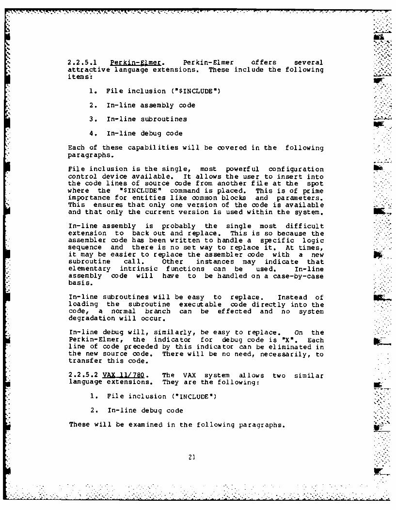
2.2.5.1 Perkin-Elmer. Perkin-Elmer offers severalattractive language extensions. These include the followingitems-
1. File inclusion ("$INCLUDE")
2. In-line assembly code -
3. In-line subroutines
4. In-line debug code
Each of these capabilities will be covered in the followingparagraphs.
File inclusion is the single, most powerful configuration 1T6control device available. It allows the user to insert intothe code lines of source code from another file at the spotwhere the "$INCLUDE" command is placed. This is of primeimportance for entities like common blocks and parameters.This ensures that only one version of the code is availableand that only the current version is used within the system.
In-line assembly is probably the single most difficultextension to back out and replace. This is so because theassembler code has been written to handle a specific logicsequence and there is no set way to replace it. At times, --it may be easier to replace the assembler code with a newsubroutine call. Other instances may indicate thatelementary intrinsic functions can be used. In-lineassembly code will have to be handled on a case-by-casebasis.
In-line subroutines will be easy to replace. Instead ofloading the subroutine executable code directly into thecode, a normal branch can be effected and no systemdegradation will occur.
In-line debug will, similarly, be easy to replace. On thePerkin-Elmer, the indicator for debug code is "X". Eachline of code preceded by this indicator can be eliminated in
. the new source code. There will be no need, necessarily, totransfer this code.
2.2.5.2 VAX 11/780. The VAX system allows two similar
language extensions. They are the following:
1. File inclusion (-INCLUDE-)
2. In-line debug code
These will be examined in the following paragraphs.
21

File inclusion on the VAX allows the user to insert into thecode lines of source code from another file at the spotwhere, the "INCLUDE" command is placed. This should be usedfor entities like common blocks and parameters. Thisensures that only one version of the code is available andthat only the current version is used within the system.This will help system configuration control.
In-line debug may not really be needed on the VAX code.There are two options available. One is to retain the debugbut convert its debug indicator symbol to that recognized bythe VAX system. The second is to convert the debug into a"formatted text report" form that is controlled throughvariables in the data base.
2.2.6 Input/Output Functions..
Input and output functions are, in general, standard on all . -
systems. However, there are always limits to theircapabilities. These usually involve the rate of datatransfer and the amount of data transfer. The math modeltends to be an input/output bound program as well asrequiring the writing of thousands of bytes of data every 60seconds.
The writing of massive quantities of data requires a finebalance between the number of I/O requests and the amount ofdata that can be physically transferred. In this respect, asingle I/O transfer request is more efficient and quickerthan several requests. However, there is a limit to theamount of data that can be transferred.
Custom written code which will transfer the maximum amountof data per call is the usual solution. However, this codeneeds to be rewritten on the new host machine to takeadvantage of its architecture.
2.2.6.1 Perkin-Elmer. The Perkin-Elmer system allows datato be written in groups of 512 byte records. However, thetotal number of groups written at any one time is less than --the actual number of bytes to be written by the model. Itis assumed that utility input and output routines have beendeveloped for use on the Perkin-Elmer system.
These utility routines can be used as the basis of similarroutines written for the VAX system. It will be fairly -straightforward to do this and locate the appropriate placesfor their calls.
2.2.6.2 VAX ll/780. The VAX system has its files organizedaround 512 byte blocks. It also only allows the writing ofapproximately 32,000 bytes at a time as a maximum. To allowthe transfer of larger amounts of data, user written and
22
. -°..,
".. . . . .. . ... .

- - -r-' r....rr r rr r~r-
developed code can be generated that will automatically
handle these larger amounts of data.
2.2.7 Assessment. ,
The purpose of this section is to illuminate discrepanciesbetween the Perkin-Elmer and VAX 11/780 machines and toindicate the recommended solution to those discrepancies. .
2.2.7.1 Constructs. In general, the constructs of ..FORTRAN 77 are the same on both machines. Mild variationsare expected but should cause no major difficulty. Anydifferences and anomalies will be addressed on acase-by-case basis.
2.2.7.2 Intinsi Functions. As shown in Figures 2 through IM5, the intrinsic functions available on both systems are thesame. This means that the calling arguments, defaultvalues, and error conditions are the same. There are noexpected problems with intrinsic functions.
2.2.7.3 Data Manipulation Functions. Figure 6 summarizesthe data manipulation functions. There is a widediscrepancy among the types of routines and theircapabilities. However, the symbolic names used on thePerkin-Elmer system will be retained on the VAX system.Only the underlying code will be altered on the VAX.Further, this code will not be transferred back to the WW".Perkin-Elmer system since it already exists and functionscorrectly there.
2.2.7.4 Character Manipulatio Functions. These functionsshould prove to be among the easiest codes to be converted.These functions should present minimal, if any, problems.
2.2.7.5 Language Extensions. Both systems have functionallysimilar but different implementation of these functions. Acommonality will need to be decided on and a utility routineimplemented to accommodate format differences.
2.2.7.6 I F_ in The majority ofinput/output capabilities are the same. However, forcertain specific areas, a new code will need to be writtenthat will be tailored for each machine. This willnecessitate two versions of the same code running on the twomachines, but they should not need to be altered once theyare finally operational.
2.3 ASSEMBLY/MACHINE LANGUAGE.
Assembly language is, by definition, code which is writtenin machine language. It is, therefore, machine dependentand not transferable.
23
: '- : -,' -' • --. .' " -- .' '. : , ." .' -: i 'i' 'i .- ", i' •' -: .° : / . " " . . : " ", - ', . . .- - ". . " . " . . . .: . .

77i
2.3.1 Perkin-Elmer.
The Perkin-Elmer system allows for users to write anddevelop assembly language code. It is foolish to expectthat no assembly language code has been written. Inreality, it is a question of the function, how much, and thecomplexity of the code that was implemented that willdictate the ease of the transfer.
The Perkin-Elmer system also allows the user to includein-line assembly code into a FORTRAN program. Thesesections of code will be difficult to replace. In general,these sections of code will be replaced with the appropriatedata manipulation routines (see Section 1.2.3). However,this will not always be possible, and for these instancesthe logic will be replaced with subroutine calls. -
2.3.2 VAX 11/780.
The VAX 11/780 system also allows for users to write anddevelop assembly language code. Any required assemblylanguage code can be developed and made to perform the same "function as it did on the other system.
2.3.3 Assessment.
Assembly language code is nontransferable. However, onceits function can be ascertained, new code can be written toreplace it on the VAX. In addition, it may become evidentthat a new FORTRAN code, generalized for both systems, couldbe implemented to reduce the amount of assembly languagecode. Further, any assembly language code should be placedinto libraries resident on the specific machine and not beconsidered as part of the transfer.
2.4 INPUT/OUTPUT.
Input statements provide the means of transferring data fromexternal media to internal storage or from an internal fileto internal storage. Output statements provide the means oftransferring data from internal storage to external media orfrom internal storage to an internal file.
Many I/O statements have a list of entities called an I/Olist that follows the list of the I/O specifier. In inputstatements, these entities become defined with values readfrom records. In output statements, the values of theseentities are written in records.
In addition to the statements that transfer data, there areauxillary input/output statements to manipulate the externalmedium, or to inquire about or describe the properties ofthe connection to the external medium. "
24
r
- . - . . -. .. ,.4

All of these input/output conventions are covered byFORTRAN 77.
2.4.1 File Management. w-File management concerns itself with the maintenance,updating, and general management of all files. This is anoperating system function and not a programming --.consideration. As such, it is independent of FORTRAN 77standardization and is not transferable.ho2.4.1.1 Perkin-Elmer. On the Perkin-Elmer system, inputstatements can read data from external files, devices,internal files, or buffers and transfer it to internalstorage. Output statements write data from internal storageto external files, devices, internal files, or buffers.
The Perkin-Elmer operating system supports both indexed andcontiguous file types. Accessing these file types can beperformed by direct, random, or sequential methods. Inaddition, temporary or scratch files can be used and will bedeleted immediately upon completion of the program whichcreated them.
The Perkin-Elmer file manager system has a standard set ofprotocol for the management of permanent files. Theseinclude the creation, assignment, and deletion of anyidentified file. These are all standard capabilities for Pf ile management.
The Perkin-Elmer system fully supports the FORTRAN 77standard.
2.4.1.2 .VAX11/780. On the VAX system, input and outputstatements translate data from internal (binary) form toexternal (readable character) form, or vice versa. The VAXoperating system further supports sequential, direct access,indexed, and internal I/O.
The VAX file management system also has a standard set ofprotocol for the management of permanent files. Theseinclude the creation, assignment, and deletion of anyidentified file. These are all standard capabilities forf il e management.
2.4.2 File Organization.
A file is a collection of logically related records that arearranged in a specific order and treated as a unit. Thearrangement or organization of a file is determined,usually, when the file is created. There are three types offile organization. They are sequential, relative, andindexed.
25
-Vb.r

Records in a sequential file are ordered in physicalsequence. Each record, except the first, has another recordpreceding it. Each record, except the last, has anotherrecord following it. The physical order in which the -records appears is usually identical to the order in which *
the records were originally written to the file.
Records in a relative file consist of a specified number offixed-length cells ordered in physical sequence. Thesecells are numbered from 1 (the first) to N (the last). Each P.number represents the location of a record relative to thebeginning of the file. Each cell either contains a singlerecord or is empty. The cell (record) number is used torefer to specific records in the file.
Records in an indexed file are ordered by fields in therecords called keys. A key is a data field in the record ofan indexed file. When the indexed file is created, a fieldwithin the file's record is determined to be the key. Thecontents of these fields are then used to identify specificrecords for subsequent processing. The length of a fieldkey, and it's relative position in the record, are identicalfor all records in the file.
There is at least one key for an indexed file. Thismandatory key is called the primary key of the file, and hasa unique value for each record. Other keys may be definedand are called alternate keys. An alternate key consists ofa field that is held in common by, and located in the sameposition in, each record in the file. Both primary andalternate keys may be used to identify a record forretrieval. An alternate key does not need to have a uniquevalue in each record.
Access mode is the method a progran uses to retrieve andstore records in a file. The access mode is specified aspart of each I/O statement.
File organization is directly linked to auxiliary I/Ostatements. These statements open and close files, specifythe attributes of the file, determine or change the way afile or unit is assigned, reposition a file to a previousrecord, or write endfile records.
Figure 8 shows the various types of FORTRAN 77 I/Ostatements and Figure 9 shows access modes for each file .organization on the two systems.
2.4.2.1 Perkin-Elmer. As shown by Figure 8, thePerkin-Elmer system supports the FORTRAN 77 specification asfar as file organizations are concerned.
26
i r~.. .,.-§.> .. >,- .*.: ..- +i.. ..

+9.- '- +
I STATEMENT CATEGORY II ------------- +----------------------------
I FORTRAN 77 I SEQUENTIAL I DIRECT I INDEXED I INTERNAL II STATEMENT +-----------------------------+--------------+I NAME I F L U IF L U I F L U I F L U I
.---------------------------- +-------------+---------------------------
IRead I X X X X - X I X - X I X - - IWrite I X X X IX - X I X - X I X -- I
IRewrite I . . .. . . I X - X I- - - IIAccept I X X - I----- - ---IType I X X -- -I - -- ----I Print I X X - ...----- -I -----
-+-------------------------------------- --------------Notes: 1. "F" denotes formatted.
2. nL3 denotes list-directed. b.-3. "U" denotes unformatted.
Figure 8. Available I/O statements.
-------------------------------------------------------------------
I I ACCESS MODE II FILE --------- -----------------------I ORGANIZATION I SEQUENTIAL I DIRECT I KEYED I
-+--.--------------------------------------I Sequential I Yes I Yes (1) I No II Relative I Yes I Yes I No II Indexed I Yes I No I Yes I.----------- +----------------- .9---------------------------
Notes: 1. Records must be fixed-length.
Figure 9. Access modes for each file organization.
27
-
. . .. . . . . . . . . . . . . . . . . . .. . . . . .

2.4.2.2 VAX 11/780. As shown by Figure 9, the VAX systemalso supports the FORTRAN 77 specification as far as fileorganizations are concerned.
2.4.3 Assessment.
FORTRAN 77 file management and organization provides astructured manner in which to manipulate data files. Bothsystems fully support the file characteristics specified by -:FORTRAN 77. There should be no difficulty in transferring ML, ,4this type of FORTRAN code. In fact, there should be nochanges at all to any file manipulation FORTRAN code in thetransfer of the ARTBASS code.
2.5 EXECUTION.
An executable program is a collection of program units thatconsist of exactly one main program and any number,including none, of subprograms and external procedures. Therunning of the executable program is called execution.
During execution, executable statements in the program unitsare implemented and executed in the order in which theyappear. Execution of an executable program begins with theexecution of the first executable statement of the mainprogram. When an external procedure specified in a programunit is referenced, execution begins with the firstexecutable statement that follows the FUNCTION, SUBROUTINE,or ENTRY statement that specifies the referenced procedureas the name of a procedure.
This section discusses the implementation of programexecution on the two systems. In particular, overlays,tasks and processes, and task communication are discussed inthe light of how they facilitate the program execution.
2.5.1 Perkin-Elmer.
2.5.1.1 Overlays. The Perkin-Elmer system provides a meansto execute a program in an area of main memory that is notactually large enough to contain the entire task at onetime. The program linker is used to divide such a programinto nodes, a collection of modules and common blocks, whichare loaded as needed. Only one node, the root, must remainin main memory throughout the execution of the program. Theother nodes reside on, and are fetched from, disk whenneeded.
To ensure the integrity of the overlayed program, an overlaystructure must be carefully designed. This structure is atree structure that shows which nodes of a program occupy
28
-,

the same main memory at different times. The main routine
must reside in the root node throughout the execution of thetask.-
The Perkin-Elmer OVERLAY command specifies the start of anode and the node's relative position within the tree -structure. In addition, any run-time library files can bespecified so that remaining entry points can be resolved. .-...
Each node has a fixed length in bytes. The total size of atask depends on both the routine composition of each nodeand the structure of the overlay tree. An overlay structurecan be represented by a set of parallel paths. A path canbe defined as a particular set of nodes with one at eachlevel, and each of which is a descendent from the previouslevel.
Therefore, the total size of a task is determined by thepath whose node size adds up to the greatest number ofbytes. Normally, by using the cross reference map from thelinker, a manually created call-tree representation of aprogram can be generated as an aid in determining thesmallest possible task size.
Normally, the placement of a common block or global blockwithin an overlayed task is determined by where the block isreferenced. Blank common is always positioned in the root.Named common and global blocks are initially positioned by
the linker no closer to the root than any particularreference to the block.
There are two consequences to this positioning scheme. Thefirst is that named common and global entities areinitialized every time the overlay is fetched from disk.The second consequence is that two or more overlays can havetheir own separate and private copies of a common or globalentity. These copies could then contain different values.
In addition to common blocks and global entities, implicitlysaved local entities are also affected by overlaying aprogram. Suppose a program containing an implicitly savedlocal entity depends on the value of that entity to remainunchanged between invocations. The value of that entity iswell defined at one point during the program execution, butbecomes undefined at another.
2.5.1.2 Task and Process Development. The normal programdevelopment procedure is divided into three sections, eachrepresenting the three processes required to develop aprogram. These three processes are COMPILE, LINK, andEXECUTE.
29

COMPILE inputs the source code file to the compiler, startsthe compilation, outputs a source listing, checks forcompilation errors, and outputs the resultant object code ifno errors have occurred. LINK converts the object codeproduced by the COMPILE process into a task image. It alsooutputs a link map, checks for link errors, and outputs theexecutable image to the task image file if no errors haveoccurred. The EXECUTE process loads the task image,executes the task and outputs the task results. p
2.5.1.3 Task Communication. At this time, the form of theintertask communications used for the ARTBASS-M code on thePerkin-Elmer system is not known.
2.5.2 VAX 11/780.
2.5.2.1 Overlays. The VAX 11/780 uses the Virtual MemorySystem (VMS) operating system. The VMS system is a virtualmemory management system and as such it has no programoverlay capabilities.
2.5.2.2 Task and Process Deelp_ n. The VAX normalprogram development procedure is divided into four sections,each representing the processes required to develop aprogram. These four processes are EDIT, FORTRAN, LINK, andRU N.
The process of EDIT is the editing of the source code whichis resident in a program file. This is what the programmerdoes to create and alter the source program in order to makeit operate correctly.
Following the editing of the source code, the program iscompiled. The FORTRAN command inputs the source code fileto the compiler, starts the compilation, outputs a sourcelisting, checks for compilation errors, and outputs theresultant object code if no errors have occurred.
Next, the object code(s) need to be linked to form the taskimage. LINK converts the object code produced by theFORTRAN process into a task image. It also outputs a linkmap, checks for link errors, and outputs the executableimage to the task image file if no errors have occurred.
The RUN process loads the task image, executes the task and *
outputs the task results.
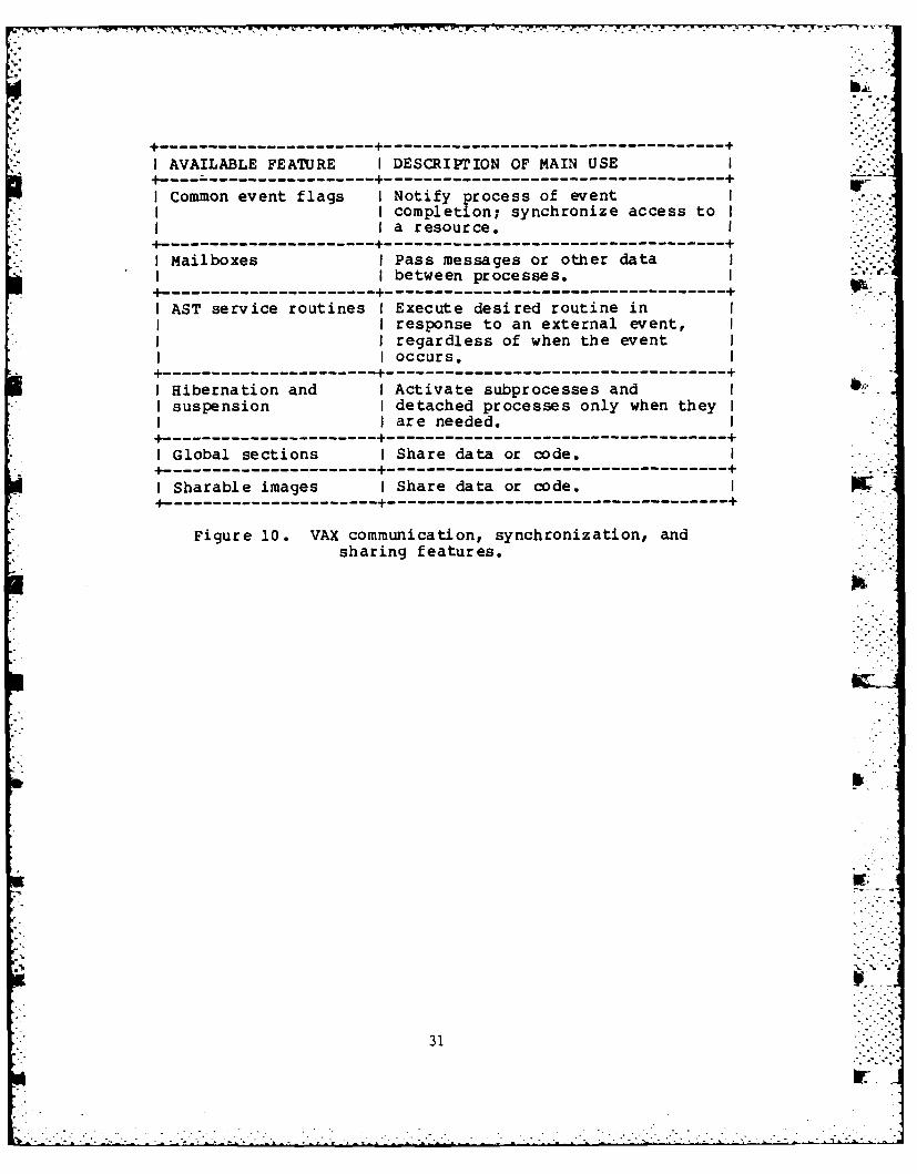
2.5.2.3 Task Communication. The VAX system offers severalfeatures to facilitate the communication interfaces betweentasks. These features can also be used in conjunction witheach other. Figure 10 lists the features available.
30 -.-.
riJ
...............-............... ,-_ i -".. i-- •.- -- -''''--".-.-i_.-ii':'_ °.,''-2'. - ' -- -''-;
W- -7 7- 7+F
IAVAILABLE FEATUlRE I DESCRIPrION OF MAIN USE--------------------- +---------------------------------------------------U
I Common event flags I Notify process of eventI I completion; synchronize access toI
a resource.I4--------------------+---------------------------------------------------
I Mailboxes I Pass messages or other dataI I between processes.
4----------------------+---------------------------------------------------
I AST service routines I Execute desired routine inII I response to an external event, I
I regardless of when the eventI occurs.
--------------------- +---------------------------------------------------
I Hibernation and I Activate subprocesses andII suspension I detached processes only when they I
I are needed.4----------------------+---------------------------------------------------
I Global sections I Share data or code.I4---------------------+------------------------------------------------------
I Sharable images I Share data or code.4----------------------+---------------------------------------------------
Figure 10. VAX communication, synchronization, andsharing features.
31

The difficulty with using these features as provided is thatthey are also used by the VAX system. Consequently, certainranges of features are not available for user applicationuse since they are reserved for system communications,synchronization, and sharing. Therefore, the full gamut isnot really available.
2.5.3 Assessment.
2.5.3.1 Overlays. Overlay structures, if used on thePerkin-Elmer system, will not be a problem to unravel. Onthe VAX system, overlaying is not supported. Allappropriate common blocks and data entities will be locatedeither in the main program or at an appropriate leveldetermined by the linker.
The only potential difficulty will be in the restoration ofthe VAX data structures onto the Perkin-Elmer system. Thiscan be minimized by the use of linker commands that forcethe location of common blocks in relationship to mainmemory.
At this time, the use of overlays for the ARTBASS-M code onthe Perkin-Elmer sytem is not known. However, if nooverlays are used, then the problems mentioned here become amoot point.
2.5.3.2 Task and Process Develoment. Both the Perkin-Elmerand VAX systems allow the same types of developmentalprocesses. What should be developed is a command file thatwill automatically compile all of the required source codeprogram files, and then link them together to create theexecutable image. As an option, this automatic command filemight also begin the task execution.
If the automatic command file does not have the taskexecution command, then one should be available as astand-alone command. Figures 11 and 12 show representativeautomatic task creation command files.
2.5.3.3 Task Communication. Real-time implications oftenconsist of related programs running as several processes.These processes may be detached processes, or detachedprocesses with one or more subprocesses. These processesusually need to communicate with each other and share commondata or code. .
The symbolic names used by the ARTBASS-M code will beretained on the VAX. The code will, however, be altered onthe VAX to conform to VAX system architecture. This newcode will not be transferred back to the Perkin-Elmer systemsince it already exists on that system and it executes -correctly. This function will probably be the mostdifficult to convert on the VAX.
32
p . . , _-

- - - - - - - - - - - - - - - - - - - - - - - - - - - - - - - - --- - --
I PROCESS DESCRIPrION I OPERATING SYSTEM COMMANDS I-I----------------------------+-------------------------------------- .I Load the compiler I LOAD F7D,30
I I ASSIGN 1,@1.FTNII I XALLOCATE @l.OBJIN,126/2 III ASSIGN 2,@l.OBJI I XALLOCATE @l.LST,IN,132/2 I
ICompile source [email protected] START f@2II I $IFG 1
I $WRITE COMPILATION ERRORS II I $CLEARII I $ENDC
4----------------------------+-------------------------------------I Delete old executable I XDELETE @l.TSKI
I I ~XALLOCATE @l.tIAP,IN,132/2 IIBuild linker commands I$BUILD LINK.CMDI
I I ESTABLISH TASKI I MAP @1.MAP, ALPHABETIC, II I ADDRESSIXREFI
I I OPTION FLOAT,DFLOAT,II I WORK=(COO,COO), II I SYSSPACE=FFFFI
I I INCLUDE @l.OBJIII SHARED GLOBAL
I LIBRARY F7RTL.OBJ/SII I BUILD @2.TSKiI I ENDII I $ENDBI
I Load linker I LOAD MTM:LINK/S,20I-- I Link the object code I START, COMMAN D- LINK. CMD, I-
II LOG-CON:I I $IFNEO 0I I $WRITE LINK ERRORSII I $CLEARII I $ENDCI
4 -- -- -- -- -- ---------- - --- -- -- 4- -- -- -- -- -- -- -- -- -- -- -- -- -- -- - - - - -1 Load the executable I LOAD @l.TSK
I I ASSIGN l,fileI
I Assign all files I
I I ASSIGN n,fileII Run task image I START4-------------------------+------------------------------------------4-
Figure 11. Perkin-Elmer task and process developmentcommand file.
33

---- - I . - - - - - -.
IPROCESS DESCRIPTION I OPERATING SYSTEM COMMANDS I __
II $OPEN/WRITE NWUT SYS$OUTPUT II open input file I $OPEN/ READ FILES 1P1' II Read source code file name I $GET: READ/END_OF_FILE-DONE I
I I FILES NAMEIII $WRITE NOJT NAME
IDelete old object I $DEL O:INAMEI.OBJ;*I Delete old listing I $DEL L: INAME I. LIS;II Compile source I $FORTRAN 5: 'NAME'-I
I I /OBJECT-O:NAME'-II I /CONTINUATIONS-75II $GOTO GETII I $DONE: CLOSE FILES 37
II $CLOSE NcXJTI----- ------------- +-------------------------------------I Delete old executable I $DELETE O:MODEL.EXEIIDelete old link map I $DELETE O:MODEL.MAPII Link I $LINK/FULL/MAP-O:MODELI
I /EXECUTABLE-O:MODELII I S:MODEL/OPTIONSI
4 *---------------------------+-------- ------------------------------I Run task I $RUN O:MODEL.EXEI----- ------------- +-------------------------------------
Figure 12. Vax task and process developmentcommand file.
34
2.6 COMMAND LANGUAGE.
The system command language is a set of commands that "W.
provide the following functions:
1. Interactive program development.• , -. ' ,"!
2. Device and data file management. ,
3. Interactive and batch program execution andcontrol.
These functions are intended for all users of a system,including application programmers, system programmers,operators, and managers.
2.6.1 Perkin-Elmer.
The Perkin-Elmer system provides a set of command languagecommands. The most important of these commands is the logincommand which allows the user to access the system. Thisinvolves some type of user name and a password. The systemthen validates that the user is authorized to use thesystem.
The Perkin-Elmer system then provides an operatingenvironment once it is ready to accept commands. Thisenvironment has various characteristics associated with it,among which are the following:
1. An account number,
2. A user identification code,
3. A default disk device and directory name,
4. Default devices for input, output, and errorstreams,
5. A set of privileges and resource quotas, and
6. A command interpreter.
These characteristics are unique to each user.
Commands consist of English language words that describewhat the system is to do. Commands can optionally bemodif ied.
Using these commands, the user can create, access, andupdate data files and programs. The Perkin-Elmer system h-_
35
- ° - -° . • - , °. . . ' ° " - ' . ° " °. • • ... - . -. ..... .-.. . . . , . . . o . , . ,.- . .. .. •. . ° , ° ... J .
.' a . .-" " ' - .-' .L' .. ' ' -. ' : - . " "* "'"" • " " ' " " . . " -• " '

provides the access and control capabilities that are calledfor by the commands.
The Perkin-Elmer operating system provides concurrenttime-sharing multiprogramming and batch job processing. Aspart of its programming environment, the Perkin-Elmer systemprovides the following:
1. Commands for program development,
2. Debugging programs,
3. Traceback information, and
4. Exit and condition handlers.
2.6.2 VAX 11/780.
The VAX system provides an extensive set of DCL (DIGITALCommand Language) commands. The most important of thesecommands is the login command which allows the user toaccess the system. This involves a user name and apassword. The system then validates that the user isauthorized to use the system.
The VAX system provides an operating environment when it isready to accept commands. This environment has variousassociated characteristics. Among which are the following:
1. An account number,
2. A user identification code,
3. A default disk device and directory name,
4. Default devices for input, output, and errorstreams,
5. A set of privileges and resource quotas, and
6. A command interpreter.
These characteristics are unique to each user.
Commands consist of English language words (generally verbs)that describe what the system is to do. Commands canoptionally contain qualifiers and parameters. Qualifiersmodify a command and provide additional information on howto execute the command. Parameters describe the object ofthe command. In addition, commands may be placed into filesand the entire file interpreted as a single command. p:
36- '-.. . . . .
a - i""-'"

Using DCL commands, the user can create, access, and update W .
data files and programs. The VAX Record Management Services(RMS)-provide the access and control capabilities that arecalled for by the DCL commands. Further, files can be 6defined and accessed from within programs by using RMS orthe input/output services of the VAX/VMS operating systemdirectly.
The VAX operating system provides concurrent time-sharingmultiprogramming and batch job processing. As part of itsprogramming environment, the VAX system provides thefollowing:
1. Commands for program development;
-$EDIT
- $ FORTRAN
- $ MACRO
-S$ LINK _
RUN
2. Debugging programs;
- Local symbol table information, .
- Global symbol information, and
- Traceback information.
3. Exit and condition handlers.
2.6.3 Assessment.
No assessment can really be made here. Command language isa system dependent capability. Since both systems areinteractive systems, they have the same features. Whatdiffers is the implementation of those same features and. .capabilities. Since neither command language can betransferred to the other system, all that can be said for --
either system is that their command language is adequate forthe type of work to be performed.
2.7 CODE UNIFICATION.
After the ARTBASS-M becomes operational on the VAX system .'"':and regular development commences, it is recommended that
37

r , ; r T r r .-,.- -- ,.
new, general p~rpose service routines be developed. Theseroutines should be in the following functional areas:
1. Data manipulation
2. Character manipulation
3. Task communication
There are several reasons for this code unification. First,it will provide a commonality of source code on bothsystems. Second, the maintainability of the code willincrease since the programs will be the same on bothsystems, thus eliminating the burden of the same functionbeing performed by two different sets of code. Third, the hintegrity of the code is ensured as much as possible.Fourth, system configuration control is centralized onto onesystem.
The following sections outline the functions andcapabilities of these general service routines.
2.7.1 Data Manipulation Functions.
I is recommended that instead of using the system routinesprovided, the following set of general purpose routines beimplemented:
1. Cltar bit . - .
2. Set bit
3. Test bit
4. Put field
5. Get field
6. Address retrieval
These will be explained in the following paragraphs.
The clear bit routine (OCALL CLRBIT(al,a2)0) will clear theal-th bit in source a2. The set bit routine (OCALLSETBIT(al,a2)0) will set the al-th bit in source a2. The E.--test bit routine (ITSTBIT(al,a2)) will return the valueOfalse" if the al-th bit of source a2 is not set, and the
value "truea if it is set.
Any requirements for bit, byte, or halfword placement orextLaction as well as bit shifts should be replaced with thegeneral purpose routines to get or put a field. The
38
mu77
-7-. e-

rationale for this is to provide more flexibility betweenthe two systems, better data packing management schemes, aswell as providing, potentially, a faster algorithm.
The put field routine (OCALL PUTFLD(al,a2,a3)0) will placeal bits starting at bit position a2 in source a3. The getfield routine will consist of two versions, a signed and , ..unsigned version. The signed get field routine(OIGTFLS(al,a2,a3)0) will extract al bits starting at bitposition a2 in source a3, and it will sign extend theresult. The unsigned get field routine ("IGTFLU(al,a2,a3)0)will extract al bits starting at bit position a2 in thesource a3 and zero extend the value.
The address retrieval routine (OIADRES(al)") will return thestarting address in memory of al.
All of these routines will be written in assembly language.There will be a single set of routines for the VAX and acorresponding set for the Perkin-Elmer system. All routineswill, therefore, be working with data word formatsconstructed as usual on the respective system. All returnedvalues will also be appropriately justified for theparticular system. They would all reside in libraries whichwould not be transferred between the two systems.
2.7.2 Character Manipulation Functions.
A standard set of routines should be provided to work onboth machines without degradation of performance. Thefollowing types of routines will need to be provided:
1. Copy character data
2. Binary-to-ASCII data conversion
Character data should be transferred between words by use ofthe move character function. This function ("CALLMOVE(al,a2,a3,a4,a5)0) will copy al characters starting atposition a2 in string a3 into position a4 of string a5. B.
The binary-to-ASCII conversion routine (nCALLBINASC(al,a2,a3)") should convert to a decimal equivalentthe binary integer al into an ASCII character string a2 "characters long. If the logical value a3 is set to "true',the character string will include leading zeroes. If set toOfalse", leading zeroes will be suppressed.
2.7.3 Task Communication.
Real-time applications often consist of related programsrunning as several processes. These processes may be
39
- - - - - - - - - - - -- - - - - -- , -..

-v - C' -" " -"
detached processes, or detached processes with one or moresubprocesses. These processes usually need to communicatewith each other and to share common data or code.
Interprocess communication often consists of eventnotification, although it can also involve transmission ofmessages or other data. Processes within an application cansynchronize their operations through effectivecommunications. Processes can also share code or data toreduce the application's physical memory requirements.
Since neither system provides the type of intertaskcommunications that is really an industry recognizedstandard, an acceptable scheme should be generated. Inaddition, a readily transportable scheme is required.
The Semaphore Utility routines should provide a set of tasksynchronization primitives. This will synchronize a globalresource that is shared between two asynchronous tasks,since problems can occur if both tasks try to access (one toread and one to write, or both to write) the same globalarea.
To alleviate this problem, the two tasks can consider theglobal area as a nonsharable resource. Whenever a taskwants to access the area, the task requests its exclusiveuse. When this exclusive use is granted by the operatingsystem, the area can be processed as -desired. k.
When the task is finished with the area, it signals theoperating system that it is through with the resource sothat another task may use it. This type of mechanism usesone preassigned global event flag for each resource.
An interprocess queuing system should also be provided.This set of routines will maintain the interprocess queues. .-It allows the user to place an item on one of the queues,read it independently of its position on the queue, get thequeued item, and remove the item from the queue. Thissystem will also maintain a map of allocated blocks insecondary storage associated with the queue file.
F.
IFI
40
r i
. . ..- ..- u* . . .L•- -*.*. . .. . . . .. . . .

SECTION 3ARTBASS-M CODE TRANSFER PROCEDURES
This section deals with the physical transfer of ARTBASS-Mcode from the Perkin-Elmer to VAX and vice versa. There aretwo basic ways to perform this task. One way is a hardwarelash-up between the two systems. The second is to transfercode by means of magnetic tape.
The hardware approach would entail the connecting of a cablebetween the systems. Although feasible, this approach isnot advantageous. There are several reasons for not usingthis approach.
The first reason concerns itself with the frequency of codetransfers. In theory, there will be only one transfer ofcode from the Perkin-Elmer system to the VAX system. Codetransfer from the VAX to the Perkin-Elmer system will notnecessarily be done on a frequent basis. It would beexpected that any VAX to Perkin-Elmer transfer will be I.accomplished every three to four months. This is notfrequent enough to justify a hard cable connection betweenthe systems.
The second reason concerns itself with the speed and volumeof data to be transferred. It is expected thatapproximately 35,000 lines of code will be transferredbetween the systems roughly four times a year. It will takean hour or less to transfer all model code. This level ofspeed and volume is not enough to justify a cable connectionbetween the systems.
The third reason concerns itself with the cost,installation, and maintenance of the connection.Disregarding cost, which is an unknown quantity, theinstallation and maintenance of the connection ispotentially a very time consuming task as well as beingcostly in the long run. This also does not justify ahardware connection between the systems.
Based on the above considerations, it is recommended thatall data transfers between the Perkin-Elmer and VAX systemswill be accomplished by tape. The remainder of this sectionwill discuss the actual mechanics of the transfer between W
the systems.
3.1 FORTRAN TRANSFER.
41

- -. °.. .
3.1.1 Perkin-Elmer to VAX 11/780.
The initial transfer of Perkin-Elmer resident FORTRAN codeto the VAX will include all math model code, support code,and all necessary files. In addition, compilation listings,link load maps, and any necessary support listings will alsobe made available for the conversion work to be accomplishedon the VAX.
The transfer to tape will use the Perkin-Elmer "COPY32"system utility. A VAX compatible blocksize will bespecified. Each record of source code will be 80 bytes inlength. The file blocksize and record length will, ofcourse, be adjusted appropriately for different types offiles other than source code files.
3.1.2 VAX 11/780 to Perkin-Elmer.
Examination of the Perkin-Elmer FORTRAN VII User Guidemanual and the FORTRAN VII Reference Manual indicates thatthe VAX FORTRAN 77 is basically a subset of the FORTRAN 77used by the Perkin-Elmer system. This will greatlyfacilitate the VAX developed ARTBASS-M code for itsimplementation on the Perkin-Elmer system.
As mentioned above in Section 1.2, the maximum amount of VAXsystem capabilities should be utilized. This will includethe use of the "INCLUDE" and "PARAMETER" features. Sincethe Perkin-Elmer system does not support these features asimplemented on the VAX, a program will be developed whichwill convert the VAX "INCLUDE* or "PARAMETER" format intothe Perkin-Elmer format before writing the source to thetransfer tape.
The source tape thus created on the VAX system will have thecomplete source code as well as the appropriate supportfeatures of "INCLUDE" and OPARAMETER". A program will alsobe written for the Perkin-Elmer system that will read thetape and place the source code into its respective files.
3.2 ASSEMBLY LANGUAGE TRANSFER.
3.2.1 Perkin-Elmer to VAX 11/780.
Because assembly language is system dependent, there will be rno physical transfer of this code. Instead, assembler codelistings will be used to determine the function of the code.This function will then be installed on the VAX. In someinstances, this code will be replaced by FORTRAN subroutinesto facilitate it's use on the two systems. In otherinstances, new assembler code will be written to generalize pthe function for the two systems.
42 'I
L -.- 'i < ; L .- -: --. < ,r • , . . . - , - • • . - . .

3.2.2 VAX 11/780 to Perkin-Elmer.
As mentioned above, assembler code will not be "transferred"between the two systems. Functionally identical code willbe developed, however, to perform the same logic.
3.3 SYSTEM UTILITY TRANSFER.
3.3.1 Perkin-Elmer to VAX 11/780.
In general, wherever possible, system utilities will be usedto create tapes of source code and support files. Thesesystem utility created tapes will be used to transport allnecessary entities to the VAX system.
As mentioned above in Section 3.1, some tailor-made utilityprograms will be written to minimize the system featuredifferences. These utility programs will be kept to aminimum and be as general and simple as possible.
3.3.2 VAX 11/780 to Perkin-Elmer.
In general, special utility programs will be used toreformat the VAX code so that it can be processed directly - -
by the Perkin-Elmer system. Further discussions of this arein Sections 3.2 and 3.1 above.
3.4 SCENARIO DATA BASE PROCESSING.
3.4.1 Perkin-Elmer to VAX 11/780.
The transporting of data bases from the Perkin-Elmer systemwill consist of copying the data to a tape. The copyprocess will be performed by system utilities, withoutformats. P,
Any programs that read data bases will be examined. If thereads are by formats, the code can be transferred with nochanges. Unformatted data base reads, however, will needspecial consideration. Where possible, general purpose - •binary data read routines will be used.
3.4.2 VAX 11/780 to Perkin-Elmer.
Data base processing routines will be used on both systems.These will be written in FORTRAN except where assemblerlanguage is required to interface with system routines. Theassembler code will not be transferred, however, it'sfunctional equivalent will exist on the Perkin-Elmer system.
3.5 INPUT/OUTPUT TRANSFER.
43

3.5.1 Perkin-Elmer to VAX 11/780.
ANSI standard FORTRAN I/O processing will be transferreddirectly from system to system. This includes READ, WRITE,ENCODE, DECODE, PRINT, and TYPE statements. I/O that dealswith binary data transfer will be examined and transferredwhere possible. Assembler language level I/O will not betransfer red.
3.5.2 VAX 11/780 to Perkin-Elmer.
As far as possible, I/O processes will be retained andremain the same on the two systems. However, if a processcan be generalized and meet the ANSI FORTRAN standard, theold routine will be altered to make it more general.
Assembler language level I/O will not be transferred.
3.6 FRONT-END INTERFACE.
3.6.1 Perkin-Elmer to VAX 11/780.
The actual front-end interface is dependent on theconfiguration of the interactive system. This will dictatethe format and contents of the shared memory datastructures.
Certain front-end interfaces will be invariant between thetwo systems. These will be the event queuing system and theevent clusters. These will be handled as will the I/O code.Namely, FORTRAN based code will be transferred as unchangedas possible. Assembly level code will not be transferred.
3.6.2 VAX 11/780 to Perkin-Elmer.
Task communication, synchronization, and shared resourceswill be standard on the two systems. Subroutine calls willremain the same, but the underlying code may be different toaccommodate the particular system.
Since task communication, synchronization, and sharedresources are basically state-of-the-art, these functionswill remain unaltered. The implementation will most likelybe different on the two systems.
3.7 JOB INITIATION AND CONTROL.
3.7.1 Perkin-Elmer to VAX 11/780.
Job initiation and control is a system dependent feature.There will be no transfer of this type of code. However, asmuch as possible, command language files will be developedthat will automatically process files to be transferred tothe VAX.
44" ..~ - 1 -
ri->
, " . • _ ' -. " -- 5- 7 --. -- " r .--. c -, .--.-- - w -'- - c' .r - .-. ".- .* - - -. - - -. -
For transferring back to the Perkin-Elmer system from theVAX, a command file will be created that will automaticallyread the VAX created tape, copy the programs to theirrespective files, compile all of the programs, link theresultant object code, and execute the ARTBASS-M math model.
3.7.2 VAX 11/780 to Perkin-Elmer.
As much as possible, command language files will bedeveloped that will automatically process f iles to betransferred to the Perkin-Elmer system. In addition,automatic files will be created for compiling, linking, andexecuting the VAX ARTBASS-M code.
- - . . . . . . .. . . .' . . . -.'..
. K "
45"'

SECTION 4FRONT-END ARCHITECTURE
4.1 INTRODUCTION.
The Front-End Architecture includes all hardware andsoftware modules that are part of the man-machine interface. P
This section describes the man-mach1ine interface forCombined Arms Tactical Training System (CATTS), ARTBASS-M,NTC Test Support Driver and Mace. Each system's hardwareand major software modules are described.
4.2 HARDW:ARE.
The hardware description of each of the above systemsincludes the host computers, color graphics devices, bitpads, and alphanumeric terminals and printers.
4.2.1 CATTS.
CATTS is installed on a SIGMA 9 computer with 128k 32-bitwords of main memory, 3 disk drives, printer and 3 tapedrives. The computer supports three control stations:threat, maneuver, and fire support. The hardware to supportthe three control stations includes:
1. 1 SIGMA 9 computer
2. 1 Ramtek GX-100 color graphics processor
3. 3 Color cameras and map boards
4. 4 Super Bee alphanumeric terminal
5. 1 Audio recorder
6. 1 Simulated RATT (teletype)
7. 3 Graph tablets and pens
8. 3 Control panels
9. 4 Conrac 190 color monitors 4
10. 3 TI printers
11I. 1 Large screen display
46
Ir
- .. . . -

The interaction of the computer hardware and the CATTS modelis shown in Figure 13.
4.2.2 ARTBASS-M.
ARTBASS-M is installed on two PERKIN-ELMER 3240s with sharedmemory and one PERKIN-ELMER 3220. One of the 3240s runs the -imath model, the other 3240 handles map and graphic displaysand the 3220 handles I/O for the graph tablet and the touchsensitive keyboard. ARTBASS-M supports five controlstations: two maneuver, one threat, one fire support andone admin/log. The system includes the following hardware:
1. 2 PERKIN-ELMER 3240 computers with shared memory - ,
2. 1 PERKIN-ELMER 3220 computer
3. 5 Lexidata 3400 color graphics processors
4. 8 Lexidata 190 color monitors
5. 5 Multifunction keyboards
6. 5 graph tablets and pens
7. 7 Alphanumeric terminals
8. 7 Control station printers
The interaction of the computer hardware and the ARTBASS-Mmodel is shown in Figure 14.
4.2.3 NTC Test Support Driver.
NTC Test Support Driver is installed on a Digital VAX11/780. The math model can be interacted with from as manycontrol stations as exist in the NTC system. The hardwareat each control station is controlled by the LSI computer inthe De Anza color graphics processor. The followinghardware is required for each control station:
1. 1 De Anza VC23 color graphics processor
2. 2 VT-105 alphanumeric/graphic terminals
3. 1 Graph tablet and pen
4. 1 Control station printer
5. 1 Large screen display
47

4-)
Lp-i
'a
48-

o= 1.1. c I I
-J CA -
oc z Z La
*C%d CA ( (C a
z
(Ai -j =W Aj-
La i wL
oJt-i Z;0i-
400z0 Lai Z4cc C
M CL Cco
-j CA 4c
P.- Lfj 83- r i Li=QCA cr CE
CD 40
I.
C=La
La0-
a 0.h

.. , . _. _ v~r-_- -_ - - .. - --, . -. -. ' - - --t. . -,, : w ' .-' , -. , - - -" , -,' f . . -- - . ' -
The interaction of the VAX 11/780 containing the math modelV- and the front-end system for each control station is shown
in Figure 15.
4.2.4 Mace.
Mace consists of six Corvus Concept microcomputers sharing a20 megabyte hard disk. One Corvus microcomputer is theexecutive of the system, one is a graphics preprocessor andthe other four are the processors for each control station. P.The control stations include : 2 maneuver stations, 1admin/log station and 1 support fire station. The controlstations and executive station include the following 2hardware:
1. 6 Corvus Concept microcomputer (512KB) bir
2. 1 Corvus hard disk (20MB)
3. 1 Omninet disk server
4. 1 Corvus 8" floppy drive
5. 4 Sony video disk players
6. 1 Sony large screen display
7. 3 Sony 190 monitors hi
8. 5 Okidata microline 82A printers
9. 1 64K Microfazer serial-to-serial printer buffer
10. 4 8K Microfazer serial-to-serial printer buffers
11. 1 1/2" video cassette recorder
12. 4 Joysticks with interface
13. 5 Mouse with interface
The interconnection of the Mace equipment is shown in Figure
16.
4.2.5 Hardware Assessment.
In order to provide common modeling capabilities for ARTBASSand NTC, it is necessary to have the man-machine interfacehardware of both ARTBASS-M and NTC. The hardware shouldconsist of one NTC-control station for compatability testingand three ARTBASS-M stations for full model testing. Thefront-end hardware should consist of the following items:
50. - .
-- - -- - - - - - - - - - - - - - - - - - - - - - - - - - - - - -

7% T7v 5v vv w.W a. W ;- - --
4c ) w, *A -j
0.-I 0
c0. U, J
4c 0
In In
L&~ULJ UA.- ~ flui
U, w
I- S...U, .-
Lb~d3S
V)~ 0.Vsnivis
CDP,
CA4.4
vU
tI-
1udJ
51flL

LaJ
CC z
u M0
IJ I*: L*.J LUJ0 .
Ei -nLJ A
....- 0- .n 0 00
Lz W .I 4L& LA D an- - . 09 j(
itLO LA c -f74 Z1
LA U.j AuU:3S U.. -A
wl JC. tn ,C3 r_4S
La- C: 0 :- 52
........(.

1. 1 De Anza VC23 color graphics processor
2. 2VT-125 alphanumeric/graphic terminals
3. 1 Hitachi graph tablet and pen
4. 3 Lexidata 3400 color graphics processor
5. 3 Lexidata 19" color monitors
6. 3 Multifunction keyboards
7. 3 Summagraphics graph tablets and pens
8. 3 Perkin/Elmer OWEL 1251 alphanumeric terminals
9. 3 Control station printers
The interaction of the model and the De Anza is shown inFigure 17. and the interaction of the model and theLexidatas is shown in Figure 18.
4.3 SIMULATION CONTROL.
The simulation control includes all controller actionsnecessary to start, stop, freeze or replay the model. Eachsystem uses a different mechanism to interact with thecontroller for simulation control.
4.3.1 CAT'IS.
The CATTS math model is controlled by the simulation controlswitch on the control panel of the principal controlstation. Any of the three control stations can beidentified as the principal controller at start up time.The control switch is used to step through initializationand to display the simulation control menu during theexercise. The simulation control menu provides thefollowing functions:
1. Reinitialize
2. Replay
3. Restart
4. Terminate exercise
5. Freeze exercise
53
-: - -. '-~ . * ..- - *

-: v V w-
L.W
41
IaI=
- oc
400
.- CD 0A
I= 0 -C( ac
-i a. h.U = c
-2 CdL
CL.
CL . L
a.c
Lu 01ac L&w L.
0 i E =LJ -
4c ac
-l ..
454
. 5 - * -. . . \. . * . *
S S. . . .~ *- 54

wwrn~%
0- oC c j kLi~S = I
wwrCD CLCL
I ~-I~i.CD ;l&'
w- ,La I w iLA-J ZL CC
a-ea
c%.. 6r " C6
VI1 0D
vi. I--
LLa taLak
1
55

4.3.2 ARTBASS-M.
The ARTBASS math model is controlled by the simulationcontrol switch on the multifunction keyboard of the Fprincipal control station. Any of the five control stationscan be identified as the principal controller at start uptime. The control switch is used to step throughinitialization and to display the simulation control menuduring the exercise. The simulation control menu providesthe following functions: .
1. Reinitialize
2. Replay3. Restart
4. Terminate exercise
5. Freeze exercise
4.3.3 NTC Test Support Driver.
The Test Support Driver math model is controlled by thesimulation control menu. The simulation control menu isdisplayed on the color monitor by selecting the simulationcontrol button on the master menu (graph tablet). The menuis interacted with via the graph pen and color monitor andprovides the following simulation controls:
1. Initialize scenario
2. Save initialization
3. Save exercise
4. Save command and control
5. Begin exercise
6. Reinitialize same scenario
7. Reinitialize new scenario
8. Reinitialize interactive initialization
9. Replay exercise
10. Restart the exercise ...
56
bit
11 Terminate exercise
12. Terminate replicate
13. Terminate freeze
14. Freeze exercise
15. Replicate exercise
16. Produce end-of-game reports
The simulation control menu can only be executed from theprinciple control station. The principle control station isselected at start-up time.
4.3.4 Mace.
The Mace battle simulation is controlled by the Game Controlmodule. The Game Control module resides in the ExecutiveControl Station and is interacted with via an alphanumericinteractive menu.
4.3.5 Simulation Control Assessment.
The simulation control for the common model should beimplemented in two ways. One should be identical to theARTBASS simulation control using the multifunction keyboardson the three ARTBASS control stations. The other should beimplemented using an interactive master menu on the De Anzaand bit-pad for the NTC control station.
4.4 MAP DISPLAY.
The Map Display is the background map which is overlayed bythe military symbology. The types of map displays describedinclude video camera and map boards, 2-D digital maps, videodisk images and 3-D digital maps.
4.4.1 CATTS.
The background map display is produced by a video cameraaimed at a map board. Each control station is connected toa separate camera and has a separate map board. The cameraposition is controlled by a joy stick on the control panelof each control station. The joy stick provides thecapability of moving the camera in any direction and zoomingin or out.
The background map video signal is mixed with the graphicsymbology signal produced by the Ramtek color graphics
-*device and displayed on the color monitor.
57
• ' " -i-
- " . ' .'" ; - " " ". ' ' .'.' ''. .'" " ' *

. -,,-'.-,. .,
4.4.2 ARTBASS-M.
The background map display for ARTBASS is a digital image ofthe exercise area. The digital map can be displayed withcross-country movement or vegetation background. Bothbackgound types are generated from DMA digitized terraindata and reflect the same terrain data that is used by the .model for line of sight and cross-country movement speeds.The background maps can be overlayed by any or all of thefollowing features:
1. Contour lines
2. Hydrography
3. Lines of communication
4. Grid lines
5. Labels
In addition to the terrain map, a terrain appreciation mapis available on three control stations. The terrainappreciation presents a three-dimensional representation ofthe terrain from a controller selectable location andelevation.
The terrain map and the terrain appreciation are selectedvia a combination of inputs through the multifunctionkeyboard and the graph tablet.
4.4.3 NTC Test Support Driver.
The background map for the NTC Test Support Driver is adigital image of the exercise area. The digital map can bedisplayed with a cross-country movement background or ashaded relief background. The cross-country movement map iscreated from the same DMA data as the terrain database usedby the cross-country movement module; and therefore, themap image displayed on the color monitor matches the terrainused by the model. The shaded relief map depicts theelevation of the terrain by shading the map image accordingto a user selectable sun angle. Both map backgrounds can beoverlayed by any or all of the following features: :..
1. Contour lines
2. Built-up areas
3. Hydrography
5- 89
;- ~58 '"
r .
6%-.. , •
4. Lines of communication
5. Sun position
6. Zoom control ,F'7.
7. Map position scroll
8. Grid lines
9. Miscellaneous features
Any of the above features can be displayed with or withoutthe background map. The background maps are available insix display levels. The display levels and features areselected on the master menu using the graph pen and tablet.
4.4.4 Mace.
The background maps are stored as camera-produced images onvideo disk. The map location and zoom level are selected bythe joy stick. The joy stick provides the capability tomove in the X or Y direction and to zoom in or out. A total ...
of six zoom levels are stored on the video disk.
The correct frame is retrieved from the video disk byconverting the inputs from the joy stick to a frame number.The video signal from the video disk player is mixed withthe graphic display signal by the Syntec PGS graphic deviceand displayed on the color monitor.
4.4.5 Map Display Assessment.
The map displays for the common model should be consistentwith the ARTBASS and NTC graphic devices (Lexidata and DeAnza). Since the interfacing with these devices iscompletely different, there should be two sets of map imagesand map display software. The ARTBASS map display softwareshould be used to display the background maps for the threeARTBASS control stations and the NTC map display softwareshould be used to display the background map on the NTCcontrol station.
4.5 TACTICAL/OPERATIONAL MENUS.
The Tactical/Operational Menus provide the means by whichthe controller inputs commands to the model. Most of theinteractive menus are displayed on the color monitor andselections are made using the graph tablet. However some ofthe menus are displayed and selections are made using analphanumeric terminal or multifunction keyboard.
LI
59
°- . - S. . - 5 7 . . . . . . . . . . . ..... ,.

A
4.5.1 CATTS.
Tacti-cal/operational menus are initiated by pressing thebutton on the control panel that corresponds to the desiredaction. The menu is displayed on the color monitor and ismanipulated using the graph pen. CATTS provides the ....
following interactive menus:
1. Activate units
2. Unit location
3. Maneuver control
4. Support fire
5. Direct fire
6. Air mission
7. Air defense
8. Preplanned mission
9. Control measures
10. Resupply
11. Weather
12. Task organization
4.5.2 ARTBASS-M.
Tactical/operational menus are initiated by selecting thedesired menu from the multifunction keyboard. mhe menu isdisplayed on the color monitor and is interacted with viathe graph tablet and pen. The type of units displayed onthe menu is dependent upon button settings on themultifunction keyboard. A menu can be ignored from thegraph tablet or the multifunction keyboard. ARTBASSprovides the following interactive menus:
1. Activate units
2. Unit location 7
3. Maneuver control
4. Support fire
6 I
"- " "'- -. '. "- '- '- " '." •. " . ". 5. • " ". X"". -" ." .'...-,- " " " 2I - -" .'" . . . .- t "= . A . ..' ." -'. * ',_ ,._-'. "'m.-a I
5. Direct fire
6. Air mission
7. Air defense
8. Preplanned mission
9. Control measures
10. Resupply
11. Weather
12. Alert routing
13. Significant event
4.5.3 NTC Test Support Driver.
Tactical/operational menus are initiated by touching thebutton on the master menu with the graph pen thatcorresponds to the desired menu. The menu is displayed onthe color monitor and is interacted with via the graph penand tablet. TSD provides the following interactive menus:
1. Activate units
2. Unit location
3. Maneuver control
4. Support fire _
5. Direct fire
6. Air mission
7. Preplanned mission
8. Obstacle
9. Control measure
10. Intelligence control
11. Resupply
12. Weather
61
. - -': -"....

13. Unit bin definition
14. Task organization
4.5.4 Mace.
The Mace interactive menus are displayed on the alphanumericdisplay and are interacted with via the keyboard. The menusavailable to a controller is dependent upon the type of .control station. The following list shows the menus thatare available at each control station:
1. Executive
9 Control measures / obstacles
* Initialize units
* Set time
9 Simulation control -
2. Maneuver (1 and 2)
* Unit maneuver
* Air maneuver
e Unit engagement
3. Air/Fire
0 Artillery fire
, Air fire
4. Admin/Log
" Resupply
" Status reports
" Assessment reports
4.5.5 Menu Assessment.
To provide the capability to make changes to an interactivemenu and have it be included on both the ARTBASS and NTC
62
SAW-

station, only one menu system should exist. To staycompatible with the Perkin-Elmer ARTBASS system, the ARTBASSmenu system is the only reasonable choice.
The Perkin-Elmer menu software can be directly converted towork on the VAX ARTBASS control stations; however, the NTCcontrol station graphics processor has a horizontal pixelresolution of 512 compared with 640 for the ARTBASS graphicsprocessor. To display the ARTBASS menus on the NTC controlstation, the following changes must be made:
1. The Lexidata graphic display utilities must berewritten to work on the De Anza.
2. The time portion of the ARTBASS menu must beremoved when displayed on the NTC control station.If the default time is to be changed, it can be -.selected along with the done, repeat, and ignorecommands.
3. The rest of the interactive menu must be scaleddown by the graphic utilities to fit into 512pixels.
The interactive menus will be initiated from themultifunction keyboard on the ARTBASS stations and from themaster menu on the NTC control station.
4.6 SYMBOLOGY.
Symbology includes all graphic overlays on the map display.It includes such items as unit locations, tacticaloverviews, impacting fires and control measures.
4.6.1 CATTS.
The symbology is displayed on the color monitor once everytime-step for ground units and once every 15 seconds for airunits. The symbology is selected by pressing the buttonscorresponding to the desired symbols. The blue forcesymbology is displayed in blue and the red force symbology ..is displayed in red. The graphic display includes:
1. Unit direction of movement
2. Control measures
3. Engagement vectors
4. Air missions
63,.
. .--1 J A
. : .. -- . .------- . .- .-- _ _ .. . . . -. --- ._ T - - - -~ . T --.-- ; .-. - . l j-. . t -" , , - ' . . - . -
- - --..-
5. Impacting f ires
-6. Smoke
7. Illumination
8. FEBA
9. Minef ields -
10. Obstacles and fortifications
11. Weapon systems
12. Sensors
13. Sensor coverage
14. Visually detected enemy units
15. Command posts
4.6.2 ARTBASS-M.
The symbology is displayed on the color monitor once everytime-step for ground units and once every 15 seconds for airunits. The symbology is selected from a menu on themultifunction keyboard. The blue force symbology isdisplayed in blue and the red force symbology is displayedin red. The graphic display includes:
1. Unit direction of movement
2. Control measures
3. Engagement vectors
4. Air missions
5. Impacting fires
6. Smoke
7. Illumination
8. FEBA
9. Minefields
10. Obstacles and fortifications
64
..:.. ..-.• .-.- * .-... .. ...... ,....-.......-.. .- .,......'.....-.-.....-.......-................-. ........- •....-......... .

11. Weapon systems
12. Sensors
13. Sensor coverage
14. Visually detected enemy units15. Command posts
4.6.3 NTC Test Support Driver.
The symbology is displayed on the color monitor once everytime-step for ground units and once every 15 seconds for airunits. The symbology is also refreshed when the digital maplocation or display level is changed. The control of whichsymbology appears on the monitor is accomplished byselecting the master menu buttons that correspond to thedesired symbology. The buttons are selected via the graphpen and tablet.
The blue force symbology is displayed in blue and the redforce symbology is displayed in red. The symbology graphicdisplay includes:
1. Unit direction of movement
2. Control measures
3. Engagement vectors
4. Air missions
5. Impacting fires
6. Smoke
7. Illumination
8. FEBA
9. Minefields
10. Obstacles and fortifications
11. Local weather cells
12. International boundaries
13. Weapon systems
65
.1°r.•
14. Sensors
15. Sensor coverage
16. Visually detected enemy units
17. Command posts
4.6.4 Mace.
The Mace symbology is displayed by the Syntec PGS graphicdevice. The selection of symbology to be displayed isaccomplished by an interactive menu on each control stationthat has a color monitor. The following symbology can bedisplayed:
1. Unit (area occupied; iconic display; tactical
overview; opcode)
2. Firing lines
3. Impacting fires
4. Air strikes
5. Control measures
6. Obstacles
The symbology for the blue units is displayed in blue andthe symbology for the red units is displayed in red.
4.6.5 Symbology Assessment.
To conform with the Perkin-Elmer ARTBASS, the ARTBASSgraphic display software should be used for the common modelon the VAX. The graphic software should not require anychanges for display on the ARTBASS control stations;however, the graphic utilities and the map to pixelconversion routines must be rewritten to work on the NTCcontrol station.
The graphic symbology selection will be done on the mastermenu for the NTC control station and on the multifunction . . -
keyboard on the ARTBASS control station.
4.7 SIDE PANEL DISPLAYS.
Side panel displays inform the interactor of current modeltime, map attributes, and model status. The side paneldisplays are displayed on sections of the color monitor notused by the map and symbology.
66
......... ........- .AA......."

4.7.1 CATTS.
CATTS does not have side panel displays on the colormonitor. The only item displayed on the color monitor thatfits into the side panel category is the model time, whichis displayed in the upper left corner of the monitor.
4.7.2 ARTBASS-M.
ARTBASS displays the current model time as an overlay of the .digital map. The attributes of the displayed digital mapare displayed on the free space on the bottom of the screen.
4.7.3 NTC Test Support Driver.
The side panels of the color monitor contain informationindicating the status of the model and system. The sidepanel information includes:
1. Current simulation time
2. Map center UTM coordinates
3. Cursor UTM coordinates
4. Map attributes
.
5. Map display and zoom level
6. Master menu prompts
7. Color dictionary
4.7.4 Mace.
Mace does not provide side panel displays on the colormonitor. The only item displayed on the color monitor thatfits into the side panel category is the time, which isdisplayed on top of the background map.
4.7.5 Side Panel Assessment.
Because of the difference in resolution of the Lexidata andDe Anza, the side-panel information must be displayed indifferent screen locations. The De Anza has free space onboth sides of the map display; therefore, the mapattributes should be displayed on the screen sides for theNTC station. The Lexidata has free space on the bottom ofthe map display; therefore, the map attributes should bedisplayed on the screen bottom for the ARTBASS stations.
67

4.8 ALPHANUMERIC DISPLAYS.
The alphanumeric displays are used to keep the controller pr-informed of what is happening in the model. Alerts ofsignificant happenings in the model are displayed on the CRTand current unit status reports can be displayed uponcontroller request.
4.8.1 CATTS.
4.8.1.1 Unit SRecial Status Report. The unit special statusreport is displayed on the alphanumeric display when thestatus report function key is hit. The unit is selected byentering the unit name or number. The following unitinformation is displayed in the status report: b
1. Simulation time of the report
2. Unit name
3. Unit number
4. Unit UTM location
5. Unit operational state
6. Unit rate of movement
7. Unit altitude
8. Unit suppression level percent
9. Units surrounding vegetation class
10. Visual detected equipment
11. Ammunition current load
12. Equipment initial and current load and numbermanned I.
13. Personnel initial and current level
14. Fuel current load
4.8.1.2 Log/Admin Status The log/admin report isincluded is the unit status report.
4.8.1.3 Tactical alerts. The math model generates tacticalalerts indicating significant unit events. The eventsinclude visual detections, engagements, rate of movement -changes, obstacle encounters, and losses. The alerts are
68

assigned to a console(s) by unit. The alert routing can beupdated by the task organization menu.
A tactical alert can be printed, routed to another consolewith an attached message, or saved to be looked at in thefuture. Alerts are dropped from the display by hitting thedrop function key or a whole page of alerts can be droppedby hitting the page drop function key.
4.8.1.4 Interactor Alerts. Interactor alerts are displayedon the color monitor. The alerts identify menu errors inputby the interactor and indicate if the menu was accepted ornot.
4.8.2 ARTBASS-M.
4.8.2.1 Unit SRecia Status ReDort. The uni.L special statusreport is displayed on the alphanumeric display when thestatus report function key is hit. The unit is selected byentering the unit name or number. The following unitinformation is displayed in the status report:
1. Simulation time of the report
2. Unit name
3. Unit number
4. Unit UTM location
5. Unit operational state
6. Unit rate of movement
7. Unit altitude
8. Unit suppression level percent
9. Units surrounding vegetation class
10. Visual detected equipment I11. Ammunition current load
12. Equipment initial and current load and numbermanned
13. Personnel initial and current level
14. Fuel current load
69
.". ..°-. .. .. . .. "- . -" ... ". ....... '. . ..... .. . •...... .. . -' _ . .',.'. -,..' ..-..

If all the unit data cannot be displayed on one screen, therest of the data can be displayed by hitting the page dropkey.
yr4.8.2.2 L/ in Status Reor. The log/admin report isincluded in the unit status report.
4.8.2.3 T alerts. The math model generates tacticalalerts indicating significant unit events. The eventsinclude visual detections, engagements, rate of movement p ,
changes, obstacle encounters and losses. The alerts areassigned to a console(s) by unit. The alert routing can beupdated by the alert routing menu.
A tactical alert can be printed, routed to another consolewith an attached message or saved to be looked at in the . .future. Alerts are dropped from the display by hitting thedrop function key or a whole page of alerts can be droppedby hitting the page drop function key.
4.8.2.4 Ie. Alerts. Interactor alerts are displayedon the color monitor and on the multifunction keyboard. Thealerts identify menu input errors by the interactor andindicate if the menu was accepted or not.
4.8.3 NTC Test Support Driver.
4.8.3.1 U= S Statu Report. The unit special statusreport is displayed on on,: of the two alphanumeric displayswhen the unit status function key is hit. The unit isselected by entering the unit name. The followinginformation is displayed on the unit status report:
1. Simulation time of report
2. Unit name
3. Unit number
4. Unit UTM location
5. Unit operational state
6. Unit rate of movement
7. Unit altitude
8. Unit suppression level percent
9. Units surrounding vegetation class
70

r. .
10. Visual detected equipment
4.8.3.2 LoQ/Admin Status Report. The log/admin statusreport is displayed on one of the two alphanumeric displayswhen the log/admin function key is hit. The unit whoseassets are to be displayed on the screen is selected byentering the unit name. The log/admin report includes:
1. Simulation time of report
2. Unit name
3. Unit number
4. Unit UTM location
5. Unit operational state
6. Equipment initial and current load and numbermanned
7. Ammunition current load
8. Personnel initial and current level
9. Fuel current load
4.8.3.3 Tactical Alerts. The TSD math model generatestactical alerts indicating significant unit and exerciseevents. The events include visual detections, engagements,rate of movement changes, obstacle encounters, losses, andexercise status. The alerts to be displayed are selected byeach controller by alert category and unit via aninteractive menu on the alphanumeric display.
The tactical alerts are automatically scrolled on thealphanumeric display and may be printed on the consoleprinter.
4.8.3.4 Interactor Alerts. Interactor alerts, indicating I.interactor menu input errors and game status, are displayedon the color monitor. The alert is erased from the screenby hitting the ignore section of the alert with the graphpen.
4.8.4 Mace.
4.8.4.1 Unit Secial Status Report. A unit special statusreport is available on the ALOG console to show the currentstatus of a selected unit. The status report is selectedvia a menu and the unit is selected by entering the unitopcode. b
71

4.8.4.2 /Adn Status Report. A log/admin status reportis available on the ALOG console to show the current levelof petsonnel and equipment for a selected unit. The reportis selected via a menu and the unit is selected by enteringthe unit opcode.
4.8.4.3 a Alerts. Instead of tactical alerts, Maceprovides loss reports which are displayed at the ALOGconsole. The loss reports can be printed and delivered tothe appropriate controller.
4.8.4.4 Interactor Alerts. Interactor alerts do not exist
in Mace.
4.8.5 ohanumeric Disay Assesme.nt.b
To avoid complications in making changes to alerts or statusreports, only one alert and status system should beimplemented into the common model. Being it is necessary toconform to the Perkin-Elmer ARTBASS system, the ARTBASS -alert and status report system should be implemented on both _qtypes of control stations. The implementation of theARTBASS alert and status system should not require anychanges to work on the ARTBASS control stations attached tothe VAX. However, for the alerts and status reports to workon the NTC control station, the low level routinescontaining the terminal I/O commands must be rewritten tointeract with the VT-125 instead of the P/E 1251.
72
-... .. . . . . . . . . . . *

L:
DISTRIBUTION LIST
DEPARTMENT OF DEFENSE DEPARTMENT OF DEFENSE (Continued)
Armed Forces StafT College Principal Dep Under Sec of Def, Rsch & EngrgATTN: Library ATTN: J. Wade Jr.
Assist to the Sec of Def, Atomic Energy Program Analysis & EvaluationATTN: Mil Appl, C. Field ATTN: S. JohnsonATTN: R. Wagner ATTN: Strat Programs
Defense Advanced Rsch Proj Agency US European CommandATTN: TTO ATTN: ECJ-3
ATTN: ECJ-5Defense Intell Agency
ATTN: Library US Natl Mil Representative, SHAPEATTN: RTS-2B Attention US Doc Ofc for
ATTN: Nuc PlansDefense Nuclear Agency ATTN: Intel
ATTN: NASF ATTN: Pol, Nuc ConceptsATTN: NATFATTN: NAWE US Readiness CommandATTN: RAAE ATTN: J-3ATTN: RAAE, K. SchwartzATTN: RAEE Under Sec of Def for PolicyATTN: RAEV ATTN: Dir Plng & Requirements, M. SheridanATTN: SPSSATTN: SPTD Under Secy of Def for Rsch & EngrgATTN: STBE ATTN: K. HinmanATTN: STNAATTN: STRA United States Central CommandATTN: STSP ATTN: CCJ3-OX, Daigneault
4 cys ATTN: STTI-CADEPARTMENT OF THE ARMY ..-.
Defense Tech Info CenterD P-"T.
12 cys ATTN: DD Asst Ch of Staff for IntellATTN: DAMI-FIT
Dep Under Sec of DefATTN: S&TNF, T. Jones Chemical Rsch & Dev Ctr
ATTN: SMCCR-OPRField Command, DNA, Det 2Lawrence Livermore National Lab Dep Ch of Staff for Ops & Plans
ATTN: FC-I ATTN: DAMO-NCNATTN: DAMO-RQA, Firepower Div
DNA PACOM Liaison Ofc ATTN: DAMO-RQSATTN: J. Bartlett ATTN: DAMO-SSM, Pol-Mil Div
ATTN: Tech AdvisorField Command, Defense Nuclear Agency 5 cys ATTN: DAMO-NC, Nuc Chem Dir
ATTN: FCPRWATTN: FCTT, W. Summa National Training CtrATTN: FCTXE ATTN: TAF-NBC
Interservice Nuc Wpns School US Army Armament Rsch Dev & Cmd IATTN: Doc Control ATTN: DRDAR-LCN-E
Joint Chiefs of Staff US Army Ballistic Rsch LabATTN: J-3, Strat Opns Div ATTN: DRDAR-BLA-S, Tech LibATTN: J-5, Nuc/Chem Plcy Br, J. Steckler ATTN: DRDAR-BLVATTN: J-5, Nuc Div/Strat Div ATTN: R. ReislerATTN: J-5, Strat Div, W. McClainATTN: JAD/SFO US Army Chemical SchoolATTN: JAD/SSD ATTN: ATZM-CM-F -
ATTN: ATZN-CM-CCNational Defense University ATTN: ATZN-CM-N
ATTN: NWCLB-CRUS Army Comd & General Staff College
Ofc of the Sec of Def, Net Assessments ATTN: DTACATTN: Doc Control 3 cys ATTN: Combined Arms Rsch Lib
73
A- -

- -...... ........ .... "" *
DEPARTMENT OF THE ARMY (Continued) DEPARTMENT OF THE ARMY (Continued)
US Army Comb Arms Combat Oev Acty ISA Military AcademyATTN: ATZL-CAP-DT ATTN: Doc LibATTN: ATZL-SWNATTN: ATZL-SWP USA Missile CommandATTN: ATZL-SWT ATTN: DRSMI-RHATTN: ATZL-TAS-S ATTN: DRSMI-XF
US Army Concepts Analysis Agency V CorpsATTN: CSSA-ADL, Tech Lib ATTN: G-2
ATTN: G-3US Army Engineer School
ATTN: Library VII CorpsATTN: G-2
US Army Europe & Seventh Army ATTN: G-3ATTN: AEAGC-NC-C
DEPARTMENT OF THE NAVYUS Army Forces Command
ATTN: AF-OPTS Marine CorpsATTN: AFOP-TN ATTN: Code OTOO-31
ATTN: DCS, P&O, Requirements DivUS Army Foreign Science & Tech Ctr ATTN: DCS, P&O, Strat Plans Div
ATTN: DRXST-SD-1Marine Corps ev & Education Command
US Army Infantry Ctr & Sch ATTN: CommanderATTN: ATSH-CD-CSO
Naval Postgraduate SchoolUS Army Intel Threat Analysis Det ATTN: Code 1424, Library
ATTN: AIAIT-HINaval Research Laboratory
US Army Intell Ctr & School ATTN: Cede 2527, Tech LibATTN: ATSI-CO-CS
Naval War CollegeUS Army Logistics Ctr ATTN: Code E-I1, Tech Svc
ATTN: ATCL-OOL, S. CockrellNuclear Weapons Tng Gp, Atlantic
US Army Material Command ATTN: Nuclear Warfare DeptATTN: DRCDE-D
Nuclear Weapons Tng Gp, PacificUS Army Materiel Sys Analysis Actvy ATTN: Nuc Warfare Dept
ATTN: XS, W3JCAADEPARTMENT OF THE AIR FORCE
US Army Mobility Equip R&D CmdATTN: DRDME-WC, Tech Lib, Vault Air Force Operational Test & Eval Ctr
ATTN: OAUS Army Nuclear & Chemical Agency
ATTN: Library Air University LibraryATTN: MONA-CM ATTN: AUL-LSEATTN: MONA-NWATTN: MONA-OPS Assist Ch of Staff, Studies & AnalysisATTN: MONA-OPS, B. Thomas 2 cys ATTN: AF/SAMI, Tech Info DivATTN: MONA-OPS, J. Ratway -
Dep Ch of Staff, Plans & Opns
US Army TRADOC Sys Analysis Actvy ATTN: AFXOOR, Opns, Opnl SptATTN: ATAA-TACATTN: ATOR-TDB Foreign Technology Div
ATTN: SDUS Army Training & Doctrine Comd ATTN: TQ
ATTN: ATCD-FAATTN: ATCD-N DEPARTMENT OF ENERGY AGENCYATTN: ATiC-NC
Sandia National LaboratoriesUS Army War Col:.je ATTN: Tech Lib, 3141
ATTN: AWCAC, F. Braden, Dept of TacticsATTN: Library DEPARTMENT OF DEFENSE CONTRACTORSATTN: War Gaming Facility
Kaman TempoUS Army Comb Arms Opns Rsch Acty ATTN: C. Anderson
ATTN: ATOR-CAT-T ATTN: DASIAC
74

DEPARTMENT OF DEFENSE CONTRACTORS (Continued) DEPARTMENT OF DEFENSE CONTRACTORS (Continued
Science Applications International Corp Kaman Tempo 1
ATTN: B. Packard ATTN. DASIACATTN: D. EricksonATTN: J. BirneyATTN: J. IcklerATTN: J. MartinATTN: L. MetzgerATTN: M. DrakeATTN: P. McKeownATTN: R. Plock
bid
.. .. .. .... .....7

* 16
So~--t
586
orr
Related Documents