Research Journal of Applied Sciences, Engineering and Technology 7(23): 5034-5048, 2014 DOI:10.19026/rjaset.7.897 ISSN: 2040-7459; e-ISSN: 2040-7467 © 2014 Maxwell Scientific Publication Corp. Submitted: February 18, 2014 Accepted: April 09, 2014 Published: June 20, 2014 Corresponding Author: Kada Hartani, Electrotechnical Engineering Laboratory, University Tahar Moulay of Saida, Algeria This work is licensed under a Creative Commons Attribution 4.0 International License (URL: http://creativecommons.org/licenses/by/4.0/). 5034 Research Article Sensorless Master-slave Direct Torque Control of Permanent Magnet Synchronous Motors Based on Speed MRAS Observer in Electric Vehicle Kada Hartani, Fatima Maata and Abdelkader Merah Electrotechnical Engineering Laboratory, University Tahar Moulay of Saida, Algeria Abstract: In this study, a new sensorless master slave direct torque control of permanent magnet synchronous motors based on speed MRAS observer is proposed for a multi-machine system in electric vehicle. The speeds of both motors are estimated by using Model Reference Adaptive System (MRAS) scheme. A classical system with multi-inverter and multi-machine comprises a three-phase inverter for each machine to be controlled. Another approach consists in using only one three-phase inverter to supply several permanent magnet synchronous machines. A new DTC algorithm is used for the control of bi-machine traction system. Simulation results in MATLAB/SIMULINK indicated that the new DTC algorithm is well adapted for the synchronism of this system over a wide range of operations. Keywords: DTC, in-wheel motor, MRAS, multi-machine control, multi-machine system, traction application INTRODUCTION Multi-machine multi-converter systems can be considered as extensions of classical drives. In many applications, one motor is controlled by one converter. These systems are called single-machine single- converter systems. However, in high power applications such as traction systems, conveyer lines and steel processing, two or more machines are fed by one converter. This topology results in a light, more compact and less costly system (Matsuse et al., 2004). These systems are called multi-machine single- converter systems. Control of multi-machine single- converter systems is the subject of this study. A three- leg inverter supplies two in-wheel PMS machines in a traction system. However, several methods have been proposed for the control of multi-machine single- converter systems. In this case, a master slave based on DTC strategy has been developed. Recently, Permanent Magnet Synchronous Motors (PMSM) have been extensively analyzed as feasible candidates for variable speed Electric Vehicle (EV) traction application (Rahman and Qin, 1997). In order to improve dynamic performance of the permanent magnet synchronous in-wheel motor, Direct Torque Control (DTC) has been proposed here. Because the DTC has many potential advantages (Lixin and Limin, 2003; Sun and He, 2005; Hartani et al., 2010), for example, it is different from the conventional vector control method, where torque is controlled in the rotor reference frame via current control loops and its structure is simple, however it has high dynamic performance and has strong robustness to the parameter variety of the PMSM. In addition, the field-weakening control becomes easier because stator flux linkage can be controlled directly in the DTC system of a PMSM (Hu et al., 2002) and the method does not need accurate rotor position information. A new DTC algorithm is used for the control of a multi-machine system. Similar to a conventional DTC, the proposed method has two separate control loops. In the torque control loop, before selection of optimum voltage from the DTC look-up table, the system overall requirement is determined based on requirements of motors torque. Also, switchable master-slave control is used in the flux control loop. The method which is simulated for a two-parallel PMS machine system can be extended to a multi-machine system. Sensorless control is an attractive feature in DTC for PMSM without the speed control loop, in which no position or speed signal is needed for motor and only an initial position is needed for PMSM. But in high performance applications, usually the speed control is required. In this case, it is essential to detect the rotor speed for feedback. As discussed earlier, the use of speed sensors would cancel out the advantages of the DTC systems. Many researchers have paid great attentions to the sensorless method of DTC for PMSM not only to eliminate the cost of the speed sensor, but also to improve the reliability of the drive system. Sensorless control of permanent magnet synchronous motor drives is now receiving wide attention (Young et al., 2003; Ruzhong et al., 2008; Xiaodong and Yikang, 2007; Hao et al., 2009). The main reason is that the speed sensors spoils the ruggedness and simplicity of PMSM. In a hostile

Welcome message from author
This document is posted to help you gain knowledge. Please leave a comment to let me know what you think about it! Share it to your friends and learn new things together.
Transcript

Research Journal of Applied Sciences, Engineering and Technology 7(23): 5034-5048, 2014
DOI:10.19026/rjaset.7.897
ISSN: 2040-7459; e-ISSN: 2040-7467
© 2014 Maxwell Scientific Publication Corp.
Submitted: February 18, 2014 Accepted: April 09, 2014 Published: June 20, 2014
Corresponding Author: Kada Hartani, Electrotechnical Engineering Laboratory, University Tahar Moulay of Saida, Algeria This work is licensed under a Creative Commons Attribution 4.0 International License (URL: http://creativecommons.org/licenses/by/4.0/).
5034
Research Article
Sensorless Master-slave Direct Torque Control of Permanent Magnet Synchronous Motors Based on Speed MRAS Observer in Electric Vehicle
Kada Hartani, Fatima Maata and Abdelkader Merah Electrotechnical Engineering Laboratory, University Tahar Moulay of Saida, Algeria
Abstract: In this study, a new sensorless master slave direct torque control of permanent magnet synchronous motors based on speed MRAS observer is proposed for a multi-machine system in electric vehicle. The speeds of both motors are estimated by using Model Reference Adaptive System (MRAS) scheme. A classical system with multi-inverter and multi-machine comprises a three-phase inverter for each machine to be controlled. Another approach consists in using only one three-phase inverter to supply several permanent magnet synchronous machines. A new DTC algorithm is used for the control of bi-machine traction system. Simulation results in MATLAB/SIMULINK indicated that the new DTC algorithm is well adapted for the synchronism of this system over a wide range of operations. Keywords: DTC, in-wheel motor, MRAS, multi-machine control, multi-machine system, traction application
INTRODUCTION
Multi-machine multi-converter systems can be
considered as extensions of classical drives. In many applications, one motor is controlled by one converter. These systems are called single-machine single-converter systems. However, in high power applications such as traction systems, conveyer lines and steel processing, two or more machines are fed by one converter. This topology results in a light, more compact and less costly system (Matsuse et al., 2004). These systems are called multi-machine single-converter systems. Control of multi-machine single-converter systems is the subject of this study. A three-leg inverter supplies two in-wheel PMS machines in a traction system. However, several methods have been proposed for the control of multi-machine single-converter systems. In this case, a master slave based on DTC strategy has been developed.
Recently, Permanent Magnet Synchronous Motors (PMSM) have been extensively analyzed as feasible candidates for variable speed Electric Vehicle (EV) traction application (Rahman and Qin, 1997).
In order to improve dynamic performance of the permanent magnet synchronous in-wheel motor, Direct Torque Control (DTC) has been proposed here. Because the DTC has many potential advantages (Lixin and Limin, 2003; Sun and He, 2005; Hartani et al., 2010), for example, it is different from the conventional vector control method, where torque is controlled in the rotor reference frame via current control loops and its structure is simple, however it has high dynamic performance and has strong robustness to the parameter
variety of the PMSM. In addition, the field-weakening control becomes easier because stator flux linkage can be controlled directly in the DTC system of a PMSM (Hu et al., 2002) and the method does not need accurate rotor position information.
A new DTC algorithm is used for the control of a multi-machine system. Similar to a conventional DTC, the proposed method has two separate control loops. In the torque control loop, before selection of optimum voltage from the DTC look-up table, the system overall requirement is determined based on requirements of motors torque. Also, switchable master-slave control is used in the flux control loop. The method which is simulated for a two-parallel PMS machine system can be extended to a multi-machine system.
Sensorless control is an attractive feature in DTC for PMSM without the speed control loop, in which no position or speed signal is needed for motor and only an initial position is needed for PMSM. But in high performance applications, usually the speed control is required. In this case, it is essential to detect the rotor speed for feedback. As discussed earlier, the use of speed sensors would cancel out the advantages of the DTC systems. Many researchers have paid great attentions to the sensorless method of DTC for PMSM not only to eliminate the cost of the speed sensor, but also to improve the reliability of the drive system.
Sensorless control of permanent magnet synchronous motor drives is now receiving wide attention (Young et al., 2003; Ruzhong et al., 2008; Xiaodong and Yikang, 2007; Hao et al., 2009). The main reason is that the speed sensors spoils the ruggedness and simplicity of PMSM. In a hostile

Res. J. Appl. Sci. Eng. Technol., 7(23): 5034-5048, 2014
5035
Fig. 1: Block diagram of DTC control strategy in PMSM
environment, speed sensors cannot even mounted. The
sliding mode observer based techniques are simple and
robust against variation of machine parameters but it
suffers from chattering problem. The Model Reference
Adaptive System (MRAS) represents one of the most
attractive and popular solutions for sensorless control of
AC drives. This project introduced the speed sensorless
control of parallel connected dual PMSM by using
MRAS technique.
METHODOLOGY
Direct torque control strategy: In order to obtain a
high performance control, DTC strategy is employed in
this system. The DTC, which was presented by I
Takahashi in 1986 for an induction machine (Takahachi
and Noguchi, 1986), is based on the direct control of
the torque and flux and involves non linear hysteresis
controllers. Direct control strategies do not require the
previously mentioned reference transformation to
achieve a decoupled control of flux and torque. The
currents of the machine are indirectly controlled
through torque and flux control. Figure 1 shows the
general bloc diagram of the DTC control strategy.
Figure 2 shows the power converter voltage vectors
in a stationary αβ frame. By selecting the voltage
vectors appropriately the flux trajectory and its speed
can be controlled (Takahachi and Noguchi, 1986).
Hysteresis comparators can have different levels,
usually; the flux controller is a two-level comprator and
the torque controller a three-level comparator (Draou
and Hartani, 2012).
The stator flux linkage components Φsα and Φsβ, the
flux linkage amplitude |Φs|, the torque Tem and the flux
angle θs can be determined as follow:
Fig. 2: Space vector diagram of inverter voltage vectors
Table 1: Switching table presented by Takahashi
Secteur
--------------------------------------------------------------
τϕ
τc
1 2 3 4 5 6
1 1 V2 V3 V4 V5 V6 V1
0 V7 V0 V7 V0 V7 V0
-1 V6 V1 V2 V3 V4 V5
0 1 V3 V4 V5 V6 V1 V2
0 V0 V7 V0 V7 V0 V7
-1 V5 V6 V1 V2 V3 V4
(1)
22βα sss Φ+Φ=Φ (2)
Φ
Φ=
α
βθs
ss artg (3)
( )αββα ssssem iipT Φ−Φ=2
3 (4)
( )
( )
−=Φ
−=Φ
∫
∫
t
ssss
t
ssss
dtiRV
dtiRV
0
0
ββ
αα

Res. J. Appl. Sci. Eng. Technol., 7(23): 5034-5048, 2014
5036
The switching table presented by I Takahashi is in
Table 1.
The speed MRAS observer: The Model Reference
Adaptive System (MRAS) based estimators provide the
desired state from two different models, one is
reference model and another one is adjustable model
(Wu and Xiao, 2009; Vaclavek and Blaha, 2008;
Maogang et al., 2011; Kojabadi and Ghribi, 2006;
Jinsong et al., 2009). The error between two models is
used to estimate the unknown parameter (speed in this
case). In MRAS only adjustable model should depend
unknown parameter (Quntao and Li, 2008), the
reference model is independent of speed. The error
signal is fed into adaptation mechanism, which provides
the estimated quantity which is used to tune the
adjustable model. A sensorless control algorithm is
employed here as shown in Fig. 3. PMSM is considered
as reference model and the stator current equations are
considered as adjustable model.
In the adaptation mechanism the PI controller is
used to tune the adjustable model. The estimated rotor
speed is used for tuning of adjustable model based on
current equations of motor. Speed error is continuously
monitored to ensure negative feedback and hence
stability of overall system. The current equations of
PMSM are given as:
+Φ
−−−=
++−=
ds
rs
f
rdqs
sq
ds
rqd
q
ds
sd
vLL
iiL
R
dt
di
vL
iL
Li
L
R
dt
di
1
1
ωω
ω (5)
The above current equations can be written:
+
−−
−=
'
'
'
'
'
'1
ˆq
d
sq
d
s
s
s
dr
s
qr
s
s
q
d
v
v
Li
i
L
R
L
L
L
L
L
R
i
i
dt
d
ω
ω
(6)
where,
=
Φ+=
=
Φ+=
d
fs
dd
d
f
dd
vv
L
Rvv
ii
Lii
'
'
'
'
(7)
The Eq. (7) is having speed as variable and will be
used for adjustable model. PMSM is used as reference
Fig. 3: Structure of model reference adaptive system
model and provides id and iq. In this algorithm estimated value of rotor speed is calculated as:
[ ])0(ˆ)ˆ()ˆ(ˆrddqq
ipr iiii
s
kk ωω +′−′+′−′−+= (8)
The block diagram of sensorless DTC-PMSM
employing MRAS as speed estimator is shown in Fig. 4. The MRAS based speed estimated is implemented for PMSM drive in MATLAB. MRAS used in this system designed based on the current model of PMSM and uses PI controller.
The performance of MRAS observer is based on controller used in adaptation mechanism. Here in this case a PI controller is used to tune the adaptive model based on reference model. The controller forces the error to be zero. The better performance of the proposed observer is tested at law and high speed. In order to test the performance of the observer at law and high speed, a simulation is carried out with the reference speed from zero to 5 rad/sec and after 0, 2 sec to 100 rad/sec. Figure 5a shows the waveforms of the estimated and actual motor speeds from startup to 100 rad/ses. It is clear from Fig. 5a that speed of motor is following the reference speed. Figure 5b shows the waveforms of the speed error between the estimated speed and the actual speed. It can be concluded from the waveforms that the observer performances as well other observers. The simulation result of the proposed observer indicates that the observer performs almost as well as the ordinary shaft encoder.
Figure 5c shows the electromagnetic torque generated by PMSM as step-chang (10 Nm at 0 sec, 15 Nm at 1, 2 sec and 10 Nm at 1, 6 sec) in load torque applied to motor (Fig. 5d). Figure 5e shows three-phase stator currents of PMSM when the load torque applied to motor are changed from 10-15-10 Nm. As the load on motor is changing, the stator current is changing accordingly. Figure 5f shows the zoomed view of stator currents which are sinusoidal.
NEW MASTER SLAVE DIRECT TORQUE CONTROL
The proposed method is based on the conventional
DTC technique of permanent magnet synchronous

Res. J. Appl. Sci. Eng. Technol., 7(23): 5034-5048, 2014
5037
Fig. 4: Block diagram of sensorless DTC-PMSM drive with MRAS based speed estimator
motors (Kelecy and Lorenz, 1994; Chiasson et al.,
2002; Bidart et al., 2008, 2011). In the DTC method,
the flux and electromagnetic torque are controlled by
adjusting the magnitude and position of the stator flux
respectively. This principle is used in the proposed
method. The method is explained for a two-machine
system and can be extended to a multi-machine system
(Shibata and Hoshi, 2007). In the proposed method, a
conventional single-machine DTC strategy is
independently applied to each motor and the same
principle is extended to make it applicable to a multi-
machine DTC method. In this proposed control
strategy, there are two control loops; one for the stator
flux control and one for the electromagnetic torque as
*emT
Adjustable
model
αβ
dq
dv qv di qi
'dv
'qv
'di
'qi
Adaptation
Mécanisme
'ˆqi
'ˆdi
rω
rω
*rω
-
+
MRAS
Eq. (6) Eq. (7)
Inver
ter
sΦ
*sΦ
-
emT
αsv
βsv
αsi
βsi
αβ
abc
ai
bi
ci
aS
bS
cS
Switching
table
sΦε
Tε
Flux and torque
estimator
-
av
bv
cv
+
+
PMSM
iS
αsΦ βsΦ
cτ
Φτ
IP
Wheel

Res. J. Appl. Sci. Eng. Technol., 7(23): 5034-5048, 2014
5038
(a) Estimated and actual speed (b) The error between estimated and actual speed
(c) Electromagnetic torque (d) Stator flux
(e) Three-phase stator current (f) Zoomed view of currents
0 0.2 0.4 0.6 0.8 1 1.2 1.4 1.6 1.8 20
20
40
60
80
100
120
Time [s]
Speed [rad/s]
Reference speed
Actual speed
Estimated speed
0 0.2 0.4 0.6 0.8 1 1.2 1.4 1.6 1.8 2-1
-0.5
0
0.5
1
1.5x 10
-3
Time [s]
Speed error [rad/s]
0 0.2 0.4 0.6 0.8 1 1.2 1.4 1.6 1.8 20
5
10
15
20
25
30
35
Time [s]
Electromagnetic torque(N.m
)
Actual torque
Estimated torque
Reference torque
0 0.2 0.4 0.6 0.8 1 1.2 1.4 1.6 1.8 20
0.01
0.02
0.03
0.04
0.05
0.06
0.07
0.08
0.09
Time [s]
Stator flux [Wb]
Estimated flux
Reference flux
0 0.2 0.4 0.6 0.8 1 1.2 1.4 1.6 1.8 2-60
-40
-20
0
20
40
60
Time [s]
Stator current [A
]
ia
ib
ic
0.4 0.45 0.5 0.55 0.6-20
-10
0
10
20
Time [s]
Stator current [A
]
ia
ib
ic
Res. J. Appl. Sci. Eng. Technol., 7(23): 5034-5048, 2014
5039
(g) Estimated and actual current in d-axis (h) Estimated and actual current in q-axis
(i) Current error in d-axis (j) Current error in q-axis Fig. 5: Simulation results of sensorless DTC-PMSM drive with MRAS based speed estimator
can be seen in Fig. 6 but with different procedure for
each loop. The procedure of each control loop will be
explained thoroughly in the following section of the
study.
Electromagnetic torque control loop: The new idea in
the suggested control loop is to consider the motors
torque requirements and system overall needs before
selecting a voltage vector. This is done by designing a
new look-up table in which a three level comparator is
used in the torque control loop. The procedure is
explained below and shown in Table 1 where, -1, 0, 1
are the outputs of torque error comparator:
• If both motors require a reduction in torque, a
vector is applied to decrease torque.
• If no motor requires a torque change, then a vector
is applied such that the torque is kept constant.
• If both motors require an increase in torque, then a
vector is applied to increase the torque.
• If one motor requires a decrease in torque but the
other does not, then a vector is applied to decrease
the torque.
• If one motor requires a increase in torque but the
other does not, then a vector is applied to increase
the torque.
• If one motor requires a decrease in torque but the
other one requires an increase, then a vector is
applied such that the torque is kept constant.
Figure 7 shows the implementation of the method.
In this figure, different possible kinds of torque errors
in torque control loop are presented. The black points
are the typical position for the electromagnetic torque
of the two motors. For the conditions depicted in
Fig. 7a, a voltage vector is applied such that the torque
0 0.2 0.4 0.6 0.8 1 1.2 1.4 1.6 1.8 20
50
100
150
200
250
300
350
400
450
Time [s]
Stator current in d-axis [A]
Actual current
Estimated current
0 0.2 0.4 0.6 0.8 1 1.2 1.4 1.6 1.8 20
10
20
30
40
50
60
70
Time [s]
Stator current in d-axis [A]
Actual current
Estimated current
0 0.2 0.4 0.6 0.8 1 1.2 1.4 1.6 1.8 2-0.1
0
0.1
0.2
0.3
0.4
0.5
0.6
Time [s]
Current error in d-axis [A]
0 0.2 0.4 0.6 0.8 1 1.2 1.4 1.6 1.8 2-0.5
-0.25
0
0.25
0.5
0.75
1
1.25
1.5
Time [s]
Current error in q-axis [A]

Res. J. Appl. Sci. Eng. Technol., 7(23): 5034-5048, 2014
5040
Fig. 6: Block diagram of the new sensorless master slave DTC
Fig. 7: Different possible cases of torque errors, (a) the torque should be kept constant, (b) the torque should be increased, (c) the
torque should be decreased

Res. J. Appl. Sci. Eng. Technol., 7(23): 5034-5048, 2014
5041
Table 2: Proposed table in torque control loop
Motor 2
----------------------------------------- H -1 0 1
Motor 1 -1 -1 -1 0
0 -1 0 1
1 0 1 1
does not vary. For the conditions shown in Fig. 7b, a
voltage vector is applied to increase the torque. Also,
for the conditions presented in Fig. 7c, a voltage vector
is applied to decrease torque.
Finally, using the output of this table and the
output of the stator flux control loop, the appropriate voltage vector is selected based on the conventional
DTC switching look-up Table 2.
Stator flux control loop: Before introducing the
proposed idea, some issue must be explained regarding
parallel PMS motors. As a result of applying one
voltage vector, stator flux vector of all the parallel PMS
motors will vary instantaneously in the same direction.
Therefore:
ssss IRV
dt
d−=
Φ (9)
where,
, and sΦ = Stator voltage vector, stator current
vector and stator flux vector
respectively
Rs = The stator resistance
In the stator flux control loop, one should know
that the flux of any machine can go beyond its rated
value. According to (25) the stator flux of each
permanent magnet synchronous motor surely depends
on the applied voltage. In cases where parameters of the
motors are different, or motors load are not the same,
stator fluxes will be different, or motors load are not the
same, stator fluxes will be different. From (9) it can be
seen that the stator flux vector only depends on stator
resistance among all other parameters. Therefore, when
stator resistance are the same, one expects to see the
same flux for both machines. This is valid only at
(a) (b)
(c) (d)
0 0.2 0.4 0.6 0.8 1 1.2 1.4 1.6 1.8 2-120
-100
-80
-60
-40
-20
0
20
40
60
80
100
120
Time [s]
Actual speed (rad/s)
Reference
Motor 1
Motor 2
0 0.2 0.4 0.6 0.8 1 1.2 1.4 1.6 1.8 2-120
-100
-80
-60
-40
-20
0
20
40
60
80
100
120
Time [s]
Estimated speed (rad/s)
Reference
Motor 1
Motor 2
0.2 0.3 0.4 0.5 0.6 0.795
100
105
Time [s]
Estimated speed (rad/s)
Reference
Motor 1
Motor 2
1.2 1.3 1.4 1.5 1.6 1.7
-100
-95
Time [s]
Estimated speed (rad/s)
Reference
Motor 1
Motor 2

Res. J. Appl. Sci. Eng. Technol., 7(23): 5034-5048, 2014
5042
(e) (f)
(g) (h)
(i) (j)
0 0.2 0.4 0.6 0.8 1 1.2 1.4 1.6 1.8 2-2
-1.5
-1
-0.5
0
0.5
1
Time [s]
Speed error [rad/s]
Motor 1
0 0.2 0.4 0.6 0.8 1 1.2 1.4 1.6 1.8 2-2
-1.5
-1
-0.5
0
0.5
1
Time [s]
Speed error [rad/s]
Motor 2
0 0.2 0.4 0.6 0.8 1 1.2 1.4 1.6 1.8 2-40
-30
-20
-10
0
10
20
30
40
Time [s]
Torque [N.m
]
Motor 1
Motor 2
0 0.2 0.4 0.6 0.8 1 1.2 1.4 1.6 1.8 20
5
10
15
20
Time [s]
Load torque [N.m
]
Load 1
Load 2
0 0.2 0.4 0.6 0.8 1 1.2 1.4 1.6 1.8 20
50
100
150
200
250
300
350
400
450
Time [s]
Stator current in d-axis (motor 1) [A]
Actual current
Estimated current
0 0.2 0.4 0.6 0.8 1 1.2 1.4 1.6 1.8 2-80
-60
-40
-20
0
20
40
60
80
Time [s]
Stator current in q-axis (motor 1) [A]
Actual current
Estimated current

Res. J. Appl. Sci. Eng. Technol., 7(23): 5034-5048, 2014
5043
(k) (l)
(m) (n)
(o) (p)
0 0.2 0.4 0.6 0.8 1 1.2 1.4 1.6 1.8 2
-1.2
-1
-0.8
-0.6
-0.4
-0.2
0
0.2
0.4
0.6
Time [s]
Current error in d-axis [A]
motor 1
0 0.2 0.4 0.6 0.8 1 1.2 1.4 1.6 1.8 2-2.5
-2
-1.5
-1
-0.5
0
0.5
1
1.5
Time [s]
Current error in q-axis [A]
motor 1
0 0.2 0.4 0.6 0.8 1 1.2 1.4 1.6 1.8 20
50
100
150
200
250
300
350
400
450
Time [s]
Stator current in d-axis (motor 2) [A]
Actual current
Estimated current
0 0.2 0.4 0.6 0.8 1 1.2 1.4 1.6 1.8 2-80
-60
-40
-20
0
20
40
60
80
Time [s]
Stator current in d-axis (motor 2) [A]
Actual current
Estimated current
0 0.2 0.4 0.6 0.8 1 1.2 1.4 1.6 1.8 2
-1.2
-1
-0.8
-0.6
-0.4
-0.2
0
0.2
0.4
0.6
Time [s]
Current error in d-axis [A]
motor 2
0 0.2 0.4 0.6 0.8 1 1.2 1.4 1.6 1.8 2-2.5
-2
-1.5
-1
-0.5
0
0.5
1
1.5
Time [s]
Current error in q-axis [A]
motor 2
Res. J. Appl. Sci. Eng. Technol., 7(23): 5034-5048, 2014
5044
(q) (r)
(s) (t)
(u) (v)
0 0.2 0.4 0.6 0.8 1 1.2 1.4 1.6 1.8 2-0.1
-0.05
0
0.05
0.1
Time [s]
Stator flux (motor 2) [W
b]
actual
estimated
0 0.2 0.4 0.6 0.8 1 1.2 1.4 1.6 1.8 2-0.1
-0.05
0
0.05
0.1
Time [s]
Stator flux (motor 2) [W
b]
actual
estimated
0 0.2 0.4 0.6 0.8 1 1.2 1.4 1.6 1.8 20
0.01
0.02
0.03
0.04
0.05
0.06
0.07
0.08
0.09
Time [s]
Stator flux (motor 2) [W
b]
Motor 1
Motor 2
-0.1 -0.08 -0.06 -0.04 -0.02 0 0.02 0.04 0.06 0.08 0.1-0.1
-0.08
-0.06
-0.04
-0.02
0
0.02
0.04
0.06
0.08
0.1
Time [s]
Stator flux trajectory
Motor 1
-0.1 -0.08 -0.06 -0.04 -0.02 0 0.02 0.04 0.06 0.08 0.1-0.1
-0.08
-0.06
-0.04
-0.02
0
0.02
0.04
0.06
0.08
0.1
Time [s]
Stator flux trajectory
Motor 2
0 0.2 0.4 0.6 0.8 1 1.2 1.4 1.6 1.8 2-60
-40
-20
0
20
40
60
Time [s]
Motor current (1) [A]
is
A
isB

Res. J. Appl. Sci. Eng. Technol., 7(23): 5034-5048, 2014
5045
(w) (x)
(y)
(z)
0 0.2 0.4 0.6 0.8 1 1.2 1.4 1.6 1.8 2-60
-40
-20
0
20
40
60
Time [s]
Motor current (2) [A]
is
A
isB
0 0.2 0.4 0.6 0.8 1 1.2 1.4 1.6 1.8 2-0.1
-0.05
0
0.05
0.1
Time [s]
Stator flux (motor 1) [W
b]
Flux-sA
Flux-sB
0 0.2 0.4 0.6 0.8 1 1.2 1.4 1.6 1.8 2-0.1
-0.05
0
0.05
0.1
Time [s]
Stator flux (motor 2) [W
b]
Flux-sA
Flux-sB
0 0.2 0.4 0.6 0.8 1 1.2 1.4 1.6 1.8 2-60
-40
-20
0
20
40
60
Time [s]
Motor current (1) [A]
isa
isb
isc

Res. J. Appl. Sci. Eng. Technol., 7(23): 5034-5048, 2014
5046
(z1)
Fig. 8: Speed, torque, stator flux and motor current of two motors with proposed method using load change
steady state and during transients, the difference
between the fluxes may be observed. This difference
will also increase as motor speed decreases. For this
reason, in cases where motor loads or stator resistances
are different, speed reference cannot go below a certain
value for speed control application. Thus, as the stator
flux of one of the motors decreases, its torque
generation capability will also decrease.
For these conditions, the mean control strategy
cannot be used since the flux of the one machine can be
saturated while its average value is equal to the
reference value. Therefore, the master-slave control
technique can be used for the stator flux control loop. In
this way, only the stator flux of one motor is controlled.
But the motor with the bigger stator flux magnitude has
to be selected as the master and its stator flux is set to
the reference value. To prevent flux saturation at
different situations, the master motor may change.
Therefore, in the proposed method, switchable master-
slave technique is employed for stator flux control.
To accurately select the master motor and prevent
flux saturation, an index is needed. The product of
stator resistance and electromagnetic torque, i.e., RsTs is
selected as the index. For each motor, this product is
calculated. The motor with the smallest RsTs is chosen
as the master motor. In cases where motor parameters
are equal, the motor with the lower torque is selected as
the master. The duration and amount of difference
between indices are important in order to prevent
frequent change variation of master motor during
transients.
In the conventional DTC, the final step is the
selection of voltage vector using a look-up table. The
voltage is selected with respect to the section of the
stator flux. The proposed method uses the stator flux of
the master motor for flux sector selection.
RESULTS AND DISCUSSION
The block diagram of speed sensorless master-slave
DTC of parallel-connected dual PMSM is shown in
Fig. 6. The parameters for both motors are same as
shown in Table 3.
In order to ensure the stability of the system
composed of two PMSM connected in parallel on the
same inverter which uses the sensorless DTC "master-
slave" structure, different loads are applied to both
machines as shown on Fig. 8c. We can readily notice
that whatever values of the torque provided by the two
machines, the system is always stable.
The master machine is the one that provides the
highest torque and the difference in position between
the two machines corresponds to the theoretical basis
θ1<θ2 when the highest torque is provided by PMSM1.
For the speeds of the two machines (Fig. 8a), whether
master or slave, there is a close follow up of the
reference speed imposed by the control strategy
whatever is the value of the load applied. We notice
that the difference between the two speeds has very
satisfactory rates, which indicates the good perfection
in swapping the master and slave motors according to
the control behavior when disturbances occur. We
notice fast response of electromagnetic torques of the
two motors (master and slave) when we apply different
loads as shown in Fig. 8b, this confirms the fast and
good management in master and slave under the
conditions laid down in the algorithm of the control.
Table 3: Motor parameters
Rs
Resistance 0.03 Ω
Ld
d-axis inductance 0.2 mH
Lq
q-axis inductance 0.2 mH
Φf
Permanent magnet flux 0.08 Wb
p
Pole pairs 4
0 0.2 0.4 0.6 0.8 1 1.2 1.4 1.6 1.8 2-60
-40
-20
0
20
40
60
Time [s]
Motor current (2) [A]
isa
isb
isc
Res. J. Appl. Sci. Eng. Technol., 7(23): 5034-5048, 2014
5047
We remark the fast response of electromagnetic torque
of the two motors (master and slave) when applying
different loads, Fig. 8b, which confirms the speed and
good alternation in master and slave under the
conditions laid down in the algorithm control.
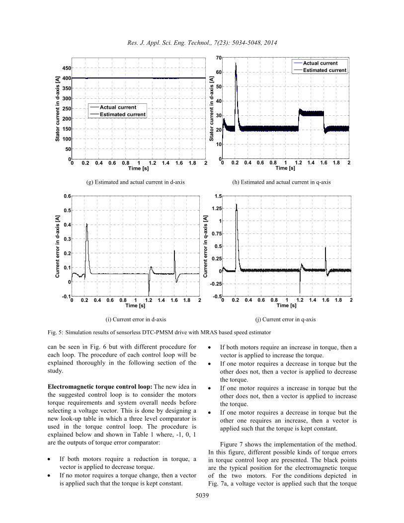
The phase currents of the two machines present
good waveforms and confirm the responses of the
motors as far as the changes in loads are concerned.
Figure 8i, j, m and n which represent the trajectories of
the stator magnetic flux show good magnetic stability
of both machines which ensures a good behavior that
was imposed by the DTC control "master-slave" to the
two machines against all disturbances. The simulation
results of this proposed method offers better steady
state response (Fig. 8).
CONCLUSION
In this study, a new sensorless master-slave direct
torque control is introduced for bi-machine single
inverter system which can be easily extended to multi-
machine traction system. The proposed method is based
on conventional DTC with speed MRAS observer.
Simulation results indicate that the performance of the
proposed method in control of bi-machine is favourable
and offers good response at steady state.
REFERENCES
Bidart, D., M. Pieterzak-David and M. Fadel, 2011.
Mono inverter multi parallel PMSM- structure and control strategy. IET Electr. Power App., 5(3): 288-294.
Bidart, D., M. Pieterzak-David, M. Fadel and
P. Maussion, 2008. Mono inverter dual parallel
PMSM structure and control strategy. Proceeding
of the 34th Annual Conference of IEEE Industrial
Electronics (IECON, 2008), pp: 3073-3078.
Chiasson, J., D. Seto, F. Sun, A. Stankovic and
S. Bortoff, 2002. Independent Control of PM motor
using a single inverter: Application to elevator
doors. Proceedings of the IEEE American Control
Conference, pp: 093-3098.
Draou, A. and K. Hartani, 2012. A novel direct torque
control scheme for PMSM for improving quality in
torque and flux. Proceeding of the International
Conference on Renewable Energy and Power
Quality (ICREPQ’12). Galicia’s Conference and
Exhibition Centre, Santiago de Compostela, Spain.
Hao, W., Z. Deng and X. Wang, 2009. Enhanced
adaptive observer for sensorless PMSM drive
system. T. China Electrotech. Soc., 24(3): 41-46.
Hartani, K., Y. Miloud and A. Miloudi, 2010. Improved
direct torque control of permanent magnet
synchronous electrical vehicle motor with
proportional-integral resistance estimator. J. Electr.
Eng. Technol., 5(3): 451-461.
Hu, Y.W., C. Tian, Y.K. Gu, Z.Q. You, L.X. Tang and
M.F. Rahman, 2002. In-depth research on direct
torque control of permanent magnet synchronous
motor. Proceedings 28th Annual Conference of the
Industrial Electronics Society (IECON, 2002), 2:
1060-1065.
Jinsong, K., Z. Xiangyun, W. Ying and H. Dahing,
2009. Study of position sensorless control of
PMSM based on MRAS. Proceeding of the IEEE
International Conference on Industrial Technology
(ICIT, 2009), pp: 1-4.
Kelecy, P.M. and R.D. Lorenz, 1994. Control
methodology for single inverter, parallel connected
dual induction motor drives for electric vehicles.
Proceeding of the 25th Annual IEEE Power
Electronics Specialists Conference (PESC’94), 2:
987-991.
Kojabadi, H.M. and M. Ghribi, 2006. MRAS-based adaptive speed estimator in PMSM drives. Proceeding of the 9th International Workshop on Advanced Motion Control, pp: 569-572.
Lixin, T. and Z. Limin, 2003. A novel direct torque
control for interior permanent magnet synchronous
machine drive with low ripple in torque and flux.
IEEE T. Ind. Appl., 39(6): 1748-1756.
Maogang, W., Z. Rongxiang and W. Junwei, 2011.
Sensorless estimation and convergence analysis
based on MRAS for PMSM. Proceeding of the 8th
World Congress on Intelligent Control and
Automation (WCICA, 2011), pp: 1641-1644.
Matsuse, K., H. Kawai, Y. Kouno and J. Oikawa, 2004.
Characteristics of speed sensorless vector
controlled dual induction motor drive connected in
parallel fed by a single inverter. IEEE T. Ind.
Appl., 40(1).
Quntao, A. and S. Li, 2008. On-line parameter
identification for vector controlled PMSM drives
using adaptive algorithm. Proceeding of the IEEE
Vehicle Power and e Propulsion Conference, pp:
1-6.
Rahman, M.A. and R. Qin, 1997. A permanent magnet hysteresis hybrid synchronous motor for electric vehicles. IEEE T. Ind. Electron., 44(1): 46-53.
Ruzhong, Y., L. Beizhi and F. Zhou, 2008. Sensorless
control of PMSMs based on parameter optimized
MRAS speed observer. Proceeding of the IEEE
International Conference on Automation and
Logistics. Qingdao, China, pp: 1573-1578.
Shibata, M. and N. Hoshi, 2007. Novel inverter
topologies for two-wheel drive electric vehicles
with two permanent magnet synchronous motors.
Proceeding of the European Conference on Power
Electronics and Applications, pp: 1-10.
Sun, D. and Y.K. He, 2005. Space vector modulation
based constant switching frequency direct torque
control for permanent magnet synchronous motor.
Proc. CSEE, 25(12): 112-116.

Res. J. Appl. Sci. Eng. Technol., 7(23): 5034-5048, 2014
5048
Takahachi, I. and T. Noguchi, 1986. A new quick-
response and high-efficiency control strategy of an
induction motor. IEEE T. Ind. Appl., 22(5):
820-827.
Vaclavek, P. and P. Blaha, 2008. Synchronous machine
drive observability analysis and sensorless control
design. Proceeding of the IEEE 2nd International
Power and Energy Conference (PECon, 2008),
pp: 265-270.
Wu, G. and X. Xiao, 2009. Speed controller of several
of servo system based on MRAS method.
Proceeding of the IEEE International Conference
on Industrial Technology (ICIT, 2009), pp: 1-5.
Xiaodong, X. and H. Yikang, 2007. Sensorless operation of PMSM based on Hybrid rotor position self-sensing scheme. Proceeding of the International Conference on Electrical Machines and Systems. Seoul, Korea, pp: 714-718.
Young, S.K., K.K. Kyoon and A.K. Young, 2003. MRAS based sensorless control of permanent magnet synchronous motor. Proceeding of the SICE Annual Conference. Fukui, Japan, August 4-6, pp: 1632-1637.
Related Documents