Research Article Orthorectification of WorldView-3 Satellite Image Using Airborne Laser Scanning Data Biswajeet Pradhan , 1,2 Ahmed A. Ahmed, 1 Subrata Chakraborty , 1 Abdullah Alamri, 3 and Chang-Wook Lee 4 1 Centre for Advanced Modelling and Geospatial Information System (CAMGIS), Faculty of Engineering and IT, University of Technology, Sydney, NSW 2007, Australia 2 Earth Observation Center, Institute of Climate Change, Universiti Kebangsaan Malaysia, 43600 UKM, Bangi, Selangor, Malaysia 3 Department of Geology and Geophysics, College of Science, King Saud University, P.O. Box 2455, Riyadh 11451, Saudi Arabia 4 Division of Science Education, Kangwon National University, Kangwondaehak-gil, Chuncheon-si, Gang-won-do 24341, Republic of Korea Correspondence should be addressed to Biswajeet Pradhan; [email protected] Received 30 July 2021; Revised 13 September 2021; Accepted 1 October 2021; Published 16 October 2021 Academic Editor: Qiu-Zhao Zhang Copyright © 2021 Biswajeet Pradhan et al. This is an open access article distributed under the Creative Commons Attribution License, which permits unrestricted use, distribution, and reproduction in any medium, provided the original work is properly cited. Satellite images have been widely used to produce land use and land cover maps and to generate other thematic layers through image processing. However, images acquired by sensors onboard various satellite platforms are affected by a systematic sensor and platform-induced geometry errors, which introduce terrain distortions, especially when the sensor does not point directly at the nadir location of the sensor. To this extent, an automated processing chain of WorldView-3 image orthorectification is presented using rational polynomial coefficient (RPC) model and laser scanning data. The research is aimed at analyzing the effects of varying resolution of the digital surface model (DSM) derived from high-resolution laser scanning data, with a novel orthorectification model. The proposed method is validated on actual data in an urban environment with complex structures. This research suggests that a DSM of 0.31 m spatial resolution is optimum to achieve practical results (root-mean-square error =0:69 m) and decreasing the spatial resolution to 20 m leads to poor results (root-mean-square error = 7:17). Moreover, orthorectifying WorldView-3 images with freely available digital elevation models from Shuttle Radar Topography Mission (SRTM) (30 m) can result in an RMSE of 7.94 m without correcting the distortions in the building. This research can improve the understanding of appropriate image processing and improve the classification for feature extraction in urban areas. 1. Introduction Increased availability of high-resolution satellite images is driving the rapid expansion in remote sensing applica- tions, including commercial, industrial, governmental, and research domains [1–10]. High-resolution satellite images are also commonly used in urban remote sensing applications, such as change detection, urban sprawl, land use/land cover mapping, environmental studies, and trans- portation [5–7]. Terrain distortions in satellite imagery off-nadir angle data acquisition require sophisticated data preprocessing algorithms to obtain useful data for these applications. The effect of relief displacement on off-nadir satellite images causes difficulty in accurately extracting features in urban areas surrounded by high-rise buildings. Joshi et al. [2] and Peng et al. [6] suggested that using elevation data or multiple images acquired from different angles in remote sensing applications, such as image classification, building detection, and city modeling, is preferable. These problems originated from the reduced pixel dimensions and off-nadir viewing. One approach to correct such geometric errors in satellite images is called orthorectification, which is the adjustment of a perspective image geometrically to an orthogonal image by transforming the coordinates from an image to the ground spaces and removing relief displacements and tilt. Hindawi Journal of Sensors Volume 2021, Article ID 5273549, 12 pages https://doi.org/10.1155/2021/5273549

Welcome message from author
This document is posted to help you gain knowledge. Please leave a comment to let me know what you think about it! Share it to your friends and learn new things together.
Transcript
Research ArticleOrthorectification of WorldView-3 Satellite Image UsingAirborne Laser Scanning Data
Biswajeet Pradhan ,1,2 Ahmed A. Ahmed,1 Subrata Chakraborty ,1 Abdullah Alamri,3
and Chang-Wook Lee 4
1Centre for Advanced Modelling and Geospatial Information System (CAMGIS), Faculty of Engineering and IT,University of Technology, Sydney, NSW 2007, Australia2Earth Observation Center, Institute of Climate Change, Universiti Kebangsaan Malaysia, 43600 UKM, Bangi, Selangor, Malaysia3Department of Geology and Geophysics, College of Science, King Saud University, P.O. Box 2455, Riyadh 11451, Saudi Arabia4Division of Science Education, Kangwon National University, Kangwondaehak-gil, Chuncheon-si,Gang-won-do 24341, Republic of Korea
Correspondence should be addressed to Biswajeet Pradhan; [email protected]
Received 30 July 2021; Revised 13 September 2021; Accepted 1 October 2021; Published 16 October 2021
Academic Editor: Qiu-Zhao Zhang
Copyright © 2021 Biswajeet Pradhan et al. This is an open access article distributed under the Creative Commons AttributionLicense, which permits unrestricted use, distribution, and reproduction in any medium, provided the original work isproperly cited.
Satellite images have been widely used to produce land use and land cover maps and to generate other thematic layers throughimage processing. However, images acquired by sensors onboard various satellite platforms are affected by a systematic sensorand platform-induced geometry errors, which introduce terrain distortions, especially when the sensor does not point directlyat the nadir location of the sensor. To this extent, an automated processing chain of WorldView-3 image orthorectification ispresented using rational polynomial coefficient (RPC) model and laser scanning data. The research is aimed at analyzing theeffects of varying resolution of the digital surface model (DSM) derived from high-resolution laser scanning data, with a novelorthorectification model. The proposed method is validated on actual data in an urban environment with complex structures.This research suggests that a DSM of 0.31m spatial resolution is optimum to achieve practical results (root-mean-square error= 0:69m) and decreasing the spatial resolution to 20m leads to poor results (root-mean-square error = 7:17). Moreover,orthorectifying WorldView-3 images with freely available digital elevation models from Shuttle Radar Topography Mission(SRTM) (30m) can result in an RMSE of 7.94m without correcting the distortions in the building. This research can improvethe understanding of appropriate image processing and improve the classification for feature extraction in urban areas.
1. Introduction
Increased availability of high-resolution satellite images isdriving the rapid expansion in remote sensing applica-tions, including commercial, industrial, governmental,and research domains [1–10]. High-resolution satelliteimages are also commonly used in urban remote sensingapplications, such as change detection, urban sprawl, landuse/land cover mapping, environmental studies, and trans-portation [5–7].
Terrain distortions in satellite imagery off-nadir angledata acquisition require sophisticated data preprocessingalgorithms to obtain useful data for these applications. The
effect of relief displacement on off-nadir satellite imagescauses difficulty in accurately extracting features in urbanareas surrounded by high-rise buildings. Joshi et al. [2] andPeng et al. [6] suggested that using elevation data or multipleimages acquired from different angles in remote sensingapplications, such as image classification, building detection,and city modeling, is preferable. These problems originatedfrom the reduced pixel dimensions and off-nadir viewing.One approach to correct such geometric errors in satelliteimages is called orthorectification, which is the adjustmentof a perspective image geometrically to an orthogonal imageby transforming the coordinates from an image to theground spaces and removing relief displacements and tilt.
HindawiJournal of SensorsVolume 2021, Article ID 5273549, 12 pageshttps://doi.org/10.1155/2021/5273549

Different from other terrain correction methods, whichdepend on the horizontal position of image pixels [11],orthorectification considers the pixel positional shift causedby the earth’s curvature and provides actual ground coordi-nates (X, Y , and Z values) for all pixels. Orthorectificationrequires a digital elevation model (DEM) and ground con-trol points (GCPs). The DEM can be obtained from a varietyof sources with various resolutions, such as Radarsat-1 andLight Detection and Ranging (LiDAR) data [12].
Several techniques and algorithms have been developedto improve the orthorectification processes and decreasethe distortions resulting from these processes. Belfiore andParente [13] compared different methods, including polyno-mial functions and rational functions, for correcting defor-mations of WorldView-2 satellite images with a variablenumber of GCPs. The rational functions were more suitablethan the other techniques for correcting deformations inWorldView-2 images. Prakash et al. [14] proposed aninverse orthorectification method, which utilizes road dataand DEM to correct geometric deformations in satelliteimages. These methods showed acceptable accuracy andimproved the road feature extraction from satellite images.Alrajhi et al. [15] developed an automatic procedure thatcan orthorectify high-resolution satellite images with noGCPs and can respond to real-time geospatial data updates.Furthermore, Whiteside and Bartolo [16] investigatedorthorectified images with the aid of the sensor’s rationalpolynomial coefficients (RPCs) and GCPs using differentialglobal positioning system (DGPS) with an accuracy of10 cm. Zhang et al. [1] proposed a new method for integratedPCI-RPC and ArcGIS-Spline tools for orthorectification insatellite images. The integrated approach improved theRMSE accuracy from 2.94m to 1.10m. Henrico et al. [15]developed an orthorectification process based on high-quality 2m DEM and applied two different GCP collectionmethods. First, field survey method with the aid of DGPSwas adopted. In the second method, TerraSAR-X-basedGCPs were acquired from Airbus Defense and Space. Themanual GCPs yielded better positional orthoimages thanthe TerraSAR-X-based GCPs [17, 18].
The above literature review shows the various orthor-ectification processing methods. However, many researchesconfined correction the image geometry based on DEMand DSM data, not on the correcting the buildings distor-tions of high-resolution satellite images. As a result, thefollowing sections present and discuss a novel orthorectifi-cation method designed for WorldView-3 data with a highoff-nadir angle. The following important questions areanswered: (1) the required resolution of DSM data to obtainpractical results and (2) whether or not using high-resolutionDSM data instead of the freely available digital elevationmodels is beneficial or is the latter sufficient for correctingterrain distortions in WorldView-3 imageries.
2. Materials and Methods
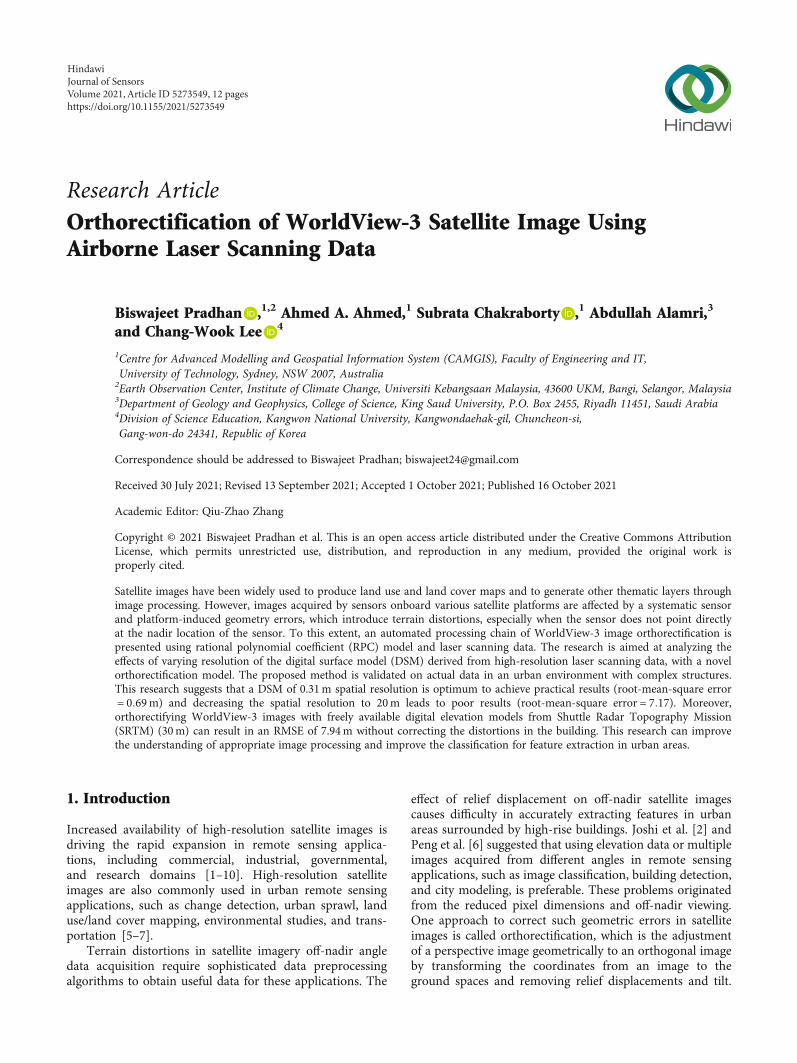
2.1. Study Area. The experiment was conducted in an arealocated in Selangor, Malaysia, that is geographically boundedbetween (101°30′-102°0′) E and (3°00′-3°30′) N. The study
area was carefully selected to successfully achieve our objec-tives. Various land uses, such as residential, commercial,industrial, public, sport, educational, and religious facilities,and land covers related to human activities are available inthe study area, as shown in Figure 1.
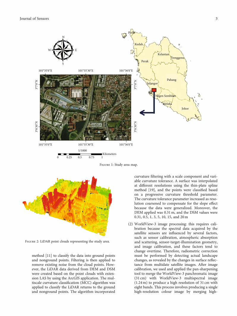
2.2. Datasets. Laser cloud points: point clouds are defined asa set of vertices in a three-dimensional coordinate system,and these clouds add a new type of geometry to the system.Point clouds, as the output of 3D scanning processes, havemany purposes, such as creating 3D models for multitudevisualization, rendering, animation, and mass customizationapplications. In this research, airborne LiDAR point cloudswere used to create an extremely high-resolution DEM anddigital surface model (DSM), as shown in Figure 2. TheLiDAR data were gathered by using an airborne system(Optech Airborne Laser Terrain Mapper 3100) on Novem-ber 2, 2015. The camera had a spatial resolution of 10 cm;the laser scanner had a scanning angle of 60° with a cameraangle of ±30° and the flying height of 1510m with clear skies.The posting density of the LiDAR data was 3–4 pts/m2 (aver-age point spacing = 0:30m) with a 25,000Hz pulse ratefrequency. The number of points is 1,300,000 points forthe study area.
WorldView-3: the WorldView-3 satellite image showedeight bands of panchromatic spatial resolution, multispec-tral, short-wave infrared, and Clouds, Aerosols, Vapours,Ice, and Snow (CAVIS) resolution at 0.31, 1.24, 3.7, and30m, respectively. The four standard VNIR colours wereblue, green, red, and near-infrared, and the additionalVNIR colours were coastal, yellow, red edge, and near-IR2. Twelve (12) CAVIS bands (atmospheric sensor) wereused, and the off-nadir angle was 14°. The data were gath-ered on April 25, 2015.
2.3. Methodology. Figure 3 shows the methodology adoptedin this research using orthorectification and involves anindirect method. The indirect method requires building theRPC model to derive at least four GCPs from DEM 30 cm.A total of 55 GCPs, which were derived from DEM of30 cm, were used. Orthorectification was applied throughArcGIS application to process the oblique images of tallbuildings. Moreover, global mapper software was used toprocess the LiDAR data, whereas ENVI was used to buildthe RPCs, radiometric calibration, geometric calculations,and filtering. Pan-sharpening was responsible for merginghigh-resolution panchromatic and low-resolution multispec-tral images of the WorldView-3 to produce a high-resolutioncolour image.
Data preparation: two distinct datasets are prepared forthis study.
(1) LiDAR data processing: it consists of multiple steps,beginning with LiDAR georeferencing. It is definedby transforming the LiDAR data coordinate systemto the Universal Transverse Mercator projectionand the world geodetic system 1984 datum by usingGlobal Mapper. The LiDAR data are classified basedon the multiscale curvature classification (MCC)
2 Journal of Sensors
method [11] to classify the data into ground pointsand nonground points. Filtering is then applied toremove existing noise from the cloud points. How-ever, the LiDAR data derived from DEM and DSMwere created based on the point clouds with exten-sion LAS by using the ArcGIS application. The mul-tiscale curvature classification (MCC) algorithm wasapplied to classify the LiDAR returns to the groundand nonground points. The algorithm incorporated
curvature filtering with a scale component and vari-able curvature tolerance. A surface was interpolatedat different resolutions using the thin-plate splinemethod [19], and the points were classified basedon a progressive curvature threshold parameter.The curvature tolerance parameter increased as reso-lution coarsened to compensate for the slope effectbecause the data were generalized. Moreover, theDEM applied was 0.31m, and the DSM values were0.31, 0.5, 1, 3, 5, 10, 15, and 20m
(2) WorldView-3 image processing: this requires cali-bration because the spectral data acquired by thesatellite sensors are influenced by several factors,such as sensor calibration, atmospheric absorptionand scattering, sensor-target-illumination geometry,and image calibration, and these factors tend tochange overtime. Therefore, radiometric correctionmust be performed by detecting actual landscapechanges, as revealed by the changes in surface reflec-tance from multidate satellite images. After imagecalibration, we used and applied the pan-sharpeningtool to merge the WorldView-3 panchromatic image(31 cm) with WorldView-3 multispectral image(1.24m) to produce a high resolution of 31 cm witheight bands. This process involves producing a singlehigh-resolution colour image by merging high-
101°35'0''E 101°35'30''E
1/1000
0 0.25 0.5 0.75 1Kilometers
101°36'0''E
101°35'0''E 101°35'30''E
N
S
EW
101°36'0''E
Perak
Kedah
KelantanTrenggenu
PahangSelangor
Negen Sembilan
MelakaJohor
Perlis
3°7'0
''N3°
6'30''
N
3°7'0
''N3°
6'30''
N
Figure 1: Study area map.
Figure 2: LiDAR point clouds representing the study area.
3Journal of Sensors

Cloud point LiDARDEM and DSM
1-Georeferencing2-Create LAS3-Filtering4-Classification5-Segmentation6-Interpolation
DEM 30cm
1-DSM31cm2-DSM50cm3-DSM1m4-DSM2m5-DSM3m6-DSM5m7-DSM10m8-DSM15m9-DSM20m
Digital elevation modelDEM 29m
Accuracyevaluation
Orthorectification
Worldview-3 withDSM (optimal)
Worldview-3 hasRPCs based DSM 31cm
Worldview-38 bands and resolution
(31cm)
Worldview-3Panchromatic
(31cm)
Worldview-3Multispectral
(1.24m)
Pansharpening
Radiometriccalibration
Reflectanceimage
RPCsbuilding
Legend
Input data
Processing
Output fromprocessing
Final results
GCPs (55)
Figure 3: Methodology used in this study.
(a) (b)
Figure 4: WorldView-3 after calibration and pan-sharpened process (a) before and (b) after.
4 Journal of Sensors
resolution panchromatic and lower-resolution multi-spectral images. The benefit of this process is toobtain multispectral resolution with high-spatialresolution. Figure 4 shows the WorldView-3 image,before and after results of the processing
Orthorectification model: the modeling involves threekey stages.
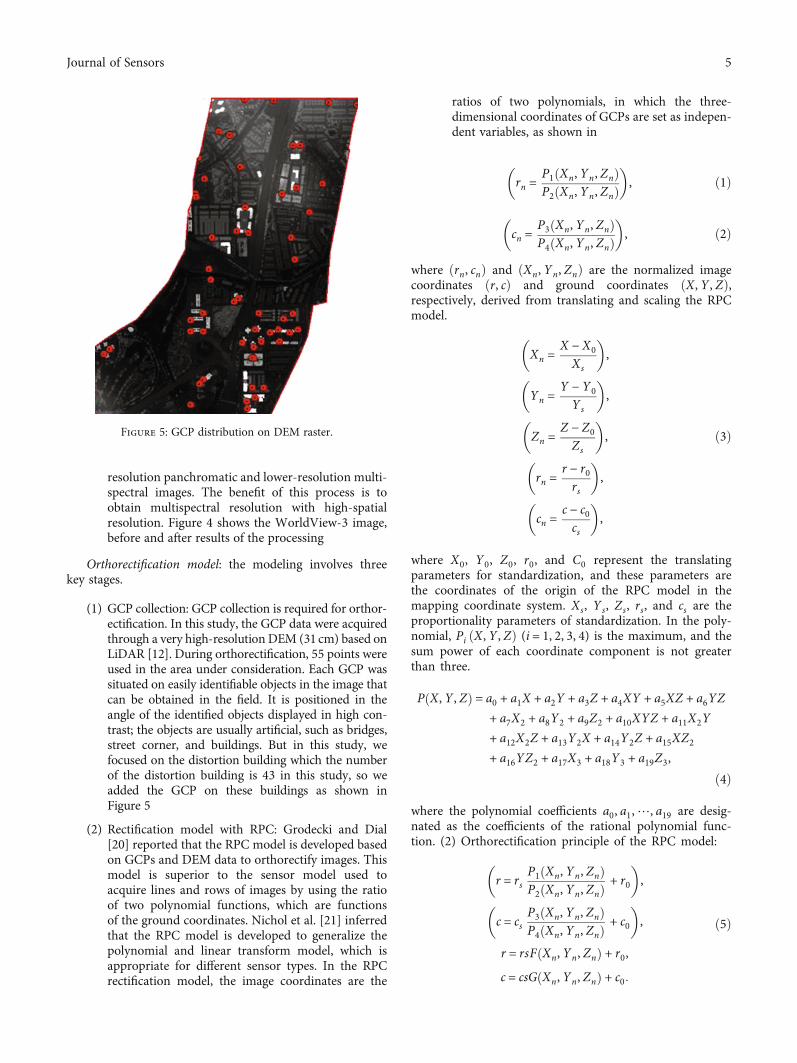
(1) GCP collection: GCP collection is required for orthor-ectification. In this study, the GCP data were acquiredthrough a very high-resolution DEM (31 cm) based onLiDAR [12]. During orthorectification, 55 points wereused in the area under consideration. Each GCP wassituated on easily identifiable objects in the image thatcan be obtained in the field. It is positioned in theangle of the identified objects displayed in high con-trast; the objects are usually artificial, such as bridges,street corner, and buildings. But in this study, wefocused on the distortion building which the numberof the distortion building is 43 in this study, so weadded the GCP on these buildings as shown inFigure 5
(2) Rectification model with RPC: Grodecki and Dial[20] reported that the RPC model is developed basedon GCPs and DEM data to orthorectify images. Thismodel is superior to the sensor model used toacquire lines and rows of images by using the ratioof two polynomial functions, which are functionsof the ground coordinates. Nichol et al. [21] inferredthat the RPC model is developed to generalize thepolynomial and linear transform model, which isappropriate for different sensor types. In the RPCrectification model, the image coordinates are the
ratios of two polynomials, in which the three-dimensional coordinates of GCPs are set as indepen-dent variables, as shown in
rn =P1 Xn, Yn, Znð ÞP2 Xn, Yn, Znð Þ
� �, ð1Þ
cn =P3 Xn, Yn, Znð ÞP4 Xn, Yn, Znð Þ
� �, ð2Þ
where ðrn, cnÞ and ðXn, Yn, ZnÞ are the normalized imagecoordinates ðr, cÞ and ground coordinates ðX, Y , ZÞ,respectively, derived from translating and scaling the RPCmodel.
Xn =X − X0Xs
� �,
Yn =Y − Y0Ys
� �,
Zn =Z − Z0Zs
� �,
rn =r − r0rs
� �,
cn =c − c0cs
� �,
ð3Þ
where X0, Y0, Z0, r0, and C0 represent the translatingparameters for standardization, and these parameters arethe coordinates of the origin of the RPC model in themapping coordinate system. Xs, Ys, Zs, rs, and cs are theproportionality parameters of standardization. In the poly-nomial, Pi ðX, Y , ZÞ (i = 1, 2, 3, 4) is the maximum, and thesum power of each coordinate component is not greaterthan three.
P X, Y , Zð Þ = a0 + a1X + a2Y + a3Z + a4XY + a5XZ + a6YZ
+ a7X2 + a8Y2 + a9Z2 + a10XYZ + a11X2Y
+ a12X2Z + a13Y2X + a14Y2Z + a15XZ2+ a16YZ2 + a17X3 + a18Y3 + a19Z3,
ð4Þ
where the polynomial coefficients a0, a1,⋯, a19 are desig-nated as the coefficients of the rational polynomial func-tion. (2) Orthorectification principle of the RPC model:
r = rsP1 Xn, Yn, Znð ÞP2 Xn, Yn, Znð Þ + r0
� �,
c = csP3 Xn, Yn, Znð ÞP4 Xn, Yn, Znð Þ + c0
� �,
r = rsF Xn, Yn, Znð Þ + r0,c = csG Xn, Yn, Znð Þ + c0:
ð5Þ
Figure 5: GCP distribution on DEM raster.
5Journal of Sensors

Let FðXn, Yn, ZnÞ = ðP1ðXn, Yn, ZnÞÞ/ðP2ðXn, Yn, ZnÞÞandGðXn, Yn, ZnÞ = ðP1ðXn, Yn, ZnÞÞ/ðP2ðXn, Yn, ZnÞÞ; then,Equation (6) can be rewritten as follows:
r = _r + ∂r∂x
ΔX + ∂r∂y
ΔY + ∂r∂z
ΔZ + r0,
r = _c + ∂c∂x
ΔX + ∂c∂x
ΔY + ∂c∂x
ΔZ + c0:
8>>><>>>:
ð6Þ
Equation (7) can be represented in Taylor formula formatas follows:
ϑr =∂r∂x
∂r∂y
∂r∂z
" # ΔX
ΔY
ΔZ
2664
3775 + r − _rð Þ,
ϑc =∂c∂x
∂c∂y
∂c∂z
� � ΔX
ΔY
ΔZ
2664
3775 + c − _cð Þ,
8>>>>>>>>>>><>>>>>>>>>>>:
ð7Þ
Figure 7: Image after orthorectification process based on different spatial resolution DSM.
Figure 6: Image prior to orthorectification.
6 Journal of Sensors

V =ϑr
ϑc
" #,
A
∂r∂x
∂r∂y
∂r∂z
∂c∂x
∂c∂y
∂c∂z
26664
37775,
Δ =ΔX
ΔY
ΔZ
2664
3775,
l =+ r − _rð Þ+ c − _cð Þ
" #: ð8Þ
Lastly, the equation can be modified in amatrix and vectorform, as follows:
V = AΔ + l, ð9Þ
where AΔ is a matrix of ΔX, ΔY ,ΔZ representing the groundcoordinates ðX, Y , ZÞ and l is the normalized imagecoordinates.
Tao et al. suggested that the least squares solution ofcoordinate corrections can be derived from Equation (10),as follows:
Δ = ΔX ΔY ΔZ½ �T = A−1 V − 1ð Þ = ATA� �−1
A−1 V − 1ð Þ:ð10Þ
(3) Orthorectification on GIS: orthorectification wasapplied using GIS tools to produce different orthor-ectified images that were derived from the integra-tion of very high-resolution image (WorldView-3)and DSM with different accuracies, such as 0.31, 1,2, 3, 5, 10, 15, and 20m. The results were comparedwith one source (WorldView-3) to investigate theoptimal image with DSM. Images can be orthorecti-fied by pixel tying to an actual location in 3-dimensional (XYZ) space; orthorectification can beachieved with a mathematical model with RPCs orwith a geometric model, which is more or less aninternal sensor model; these techniques are calledRPC orthorectification and rigorous orthorectifica-tion, respectively. Recently, several sensors, includ-ing RPCs, with image delivery systems have beenused in this regard. Developing a system for imagesthat are not associated with such RPCs is possible ifthe main properties of internal camera orientationand external environment are known. DEM, auto-mated tie point generation, and a couple of groundcontrol points can facilitate RPC orthorectificationaccurately
3. Results and Discussion
3.1. WorldView-3 Image Orthorectification-Based GCPs andLiDAR DSM. WorldView-3 was orthorectified to the finalorthoimage using the above-referenced method in Figure 6.The results are presented as nine images with different accu-racies based on varying DSM resolutions (i.e., 31 cm, 50 cm,1m, 2m, 3m, 5m, 10m, 15m, and 20m) and GCPs, asshown in Figure 7.
3.2. Accuracy Assessment. Table 1 presents the results of theminimum, maximum, and the root-mean-square error(RMSE) of orthorectified images based on different DSMresolutions with respect to the GCPs. The horizontal accu-racy of the orthorectified images is evaluated based on RMSEerror value obtained by computing changes in the coordi-nate object at a very high-resolution DEM of 31 cm to thecoordinate object in the orthoimage result. Equations (1),(2), and (3) [22] are used to determine the RMSE for Xand Y coordinates and RMSE horizontal ðX, YÞ, respec-tively.
RMSE =ffiffiffiffiffiffiffiffiffiffiffiffiffiffiffiffiffiffiffiffiffiffiffiffiffiffiffiffiffiffiffiffiffiffiffiffiffiffiffiffiffiffiffiffiffiffiffiffiffiffiffiffiffiffiffiffiffiffiffiffiffiffiffiffiffiffiffiffiffiffiffiffiffiffiffiffiffiffiffiffiffiffiffiffiffiffiffiffiffiffiffiffiffiffiffiffiffiffiffiffiffi∑n
i=1 x input − x controlj jð Þ2 + y input − y controlj jð Þ2n
r:
ð11Þ
X and Y inputs represent the coordinates of the orthoimageWorldView-3 and X control; Y control represents the coor-dinates of the intensity of the DEM at 31 cm referencepoints. The parameters n and i represent the checkpointstested for an integer between 1 to n, respectively. Table 1indicates that the RMSE was 0.638 at DSM value of 31 cm.This value increased to 0.764 when the DSM resolutionincreased to 50 cm. A consistent increase in RMSE valueswas observed between DSM 1m and 20m resolution, yield-ing RMSE values from 1.302 to 7.175. Similarly, Figure 7shows the image after orthorectification process based ondifferent spatial resolution DSM such as a1 with 31 cm and
Table 1: Summary of residual errors of GCPs for orthoimages(unit: meter).
Warp image and DSM Orthorectified image RMSE
WorldView-3 and DSM 31 cm a1 0.638
WorldView-3 and DSM 50 cm a2 0.764
WorldView-3 and DSM 1m a3 1.302
WorldView-3 and DSM 2m a4 1.718
WorldView-3 and DSM 3m a5 2.106
WorldView-3 and DSM 5m a6 3.26
WorldView-3 and DSM 10m a7 5.529
WorldView-3 and DSM 15m a8 6.501
WorldView-3 and DSM 20m a9 7.175
WorldView-3 and free DEM 30m a10 7.947
7Journal of Sensors

a2 with DSM 50 cm. The experimental results consistentlyyielded the most accurate values for validating the GCPs ofthe orthoimage based on 30 cm DSM in orthoimages. Thus,the accuracy of the orthoimages was improved reasonablybased on DSM data.
The RPC orthorectification model was applied to theWorldView-3 image based on the free source DEM of 30m
(SRTM). The result obtained indicated the highest RMSEvalue of 7.947 compared with the orthoimage, which wasobtained from high-resolution DSM of 31 cm (RMSE =0:638). The significant difference between the DSM (31 cm)and the DEM (SRTM) (30m) results indicated a unique rela-tionship between the DEM or DSM accuracy and orthorec-tification accuracy.
(a)
(b) (c) (d)
(e) (f) (g)
(h) (i) (j)
Figure 8: (a) Leaning of the building prior to orthorectification; (b–j) image after the orthorectification process and the effects of DSMaccuracy on the building lean.
8 Journal of Sensors
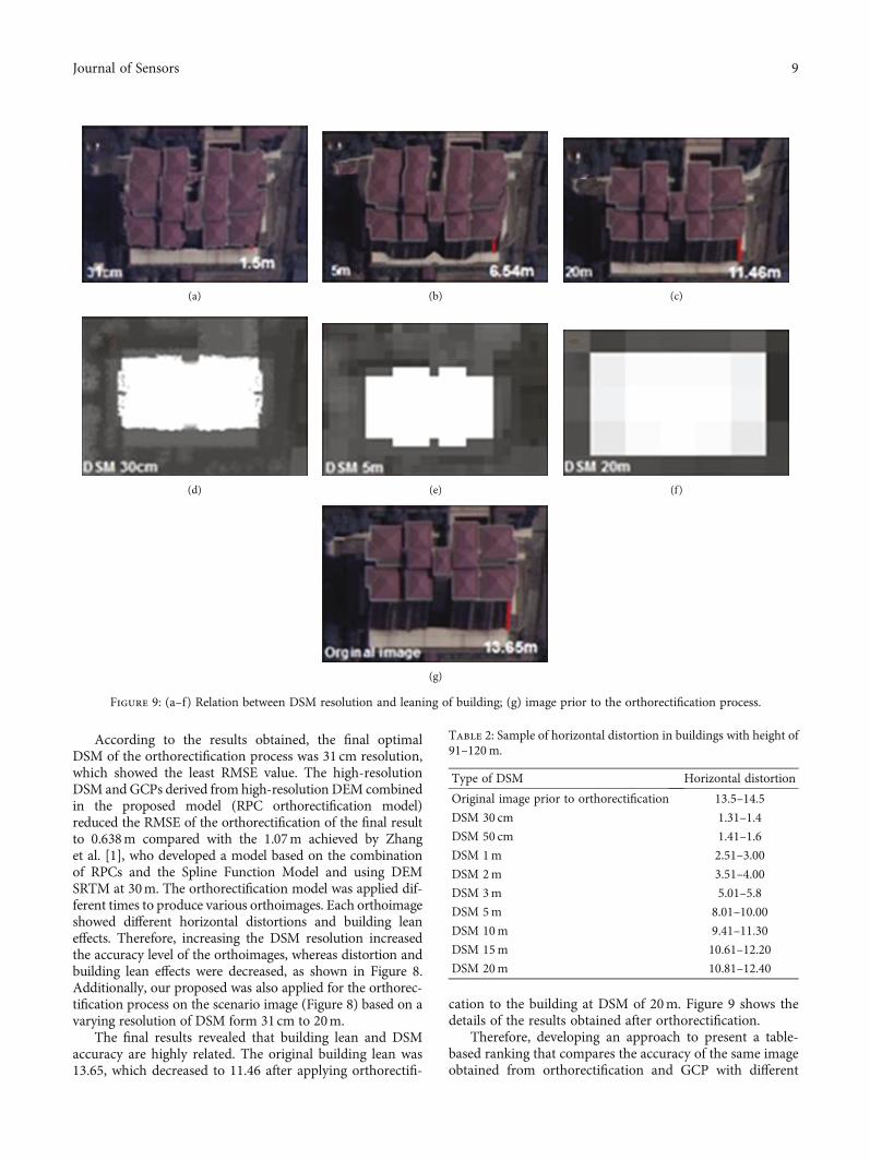
According to the results obtained, the final optimalDSM of the orthorectification process was 31 cm resolution,which showed the least RMSE value. The high-resolutionDSM and GCPs derived from high-resolution DEM combinedin the proposed model (RPC orthorectification model)reduced the RMSE of the orthorectification of the final resultto 0.638m compared with the 1.07m achieved by Zhanget al. [1], who developed a model based on the combinationof RPCs and the Spline Function Model and using DEMSRTM at 30m. The orthorectification model was applied dif-ferent times to produce various orthoimages. Each orthoimageshowed different horizontal distortions and building leaneffects. Therefore, increasing the DSM resolution increasedthe accuracy level of the orthoimages, whereas distortion andbuilding lean effects were decreased, as shown in Figure 8.Additionally, our proposed was also applied for the orthorec-tification process on the scenario image (Figure 8) based on avarying resolution of DSM form 31cm to 20m.
The final results revealed that building lean and DSMaccuracy are highly related. The original building lean was13.65, which decreased to 11.46 after applying orthorectifi-
cation to the building at DSM of 20m. Figure 9 shows thedetails of the results obtained after orthorectification.
Therefore, developing an approach to present a table-based ranking that compares the accuracy of the same imageobtained from orthorectification and GCP with different
(a) (b) (c)
(d) (e) (f)
(g)
Figure 9: (a–f) Relation between DSM resolution and leaning of building; (g) image prior to the orthorectification process.
Table 2: Sample of horizontal distortion in buildings with height of91–120m.
Type of DSM Horizontal distortion
Original image prior to orthorectification 13.5–14.5
DSM 30 cm 1.31–1.4
DSM 50 cm 1.41–1.6
DSM 1m 2.51–3.00
DSM 2m 3.51–4.00
DSM 3m 5.01–5.8
DSM 5m 8.01–10.00
DSM 10m 9.41–11.30
DSM 15m 10.61–12.20
DSM 20m 10.81–12.40
9Journal of Sensors
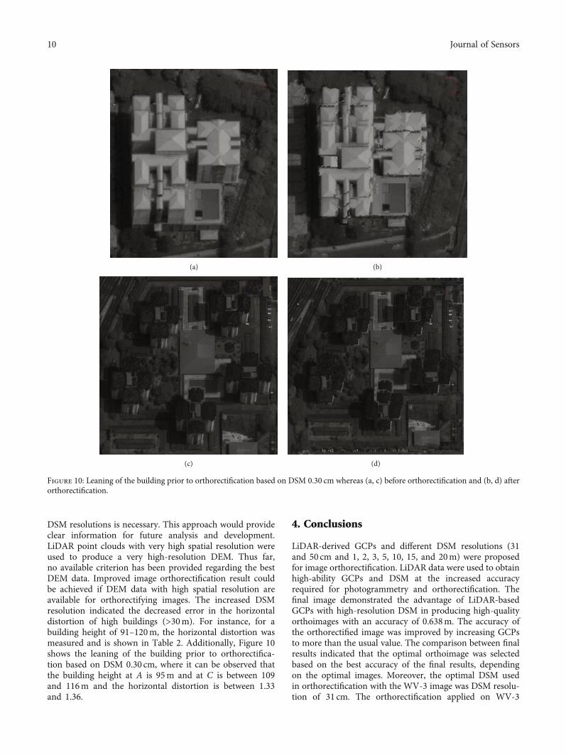
DSM resolutions is necessary. This approach would provideclear information for future analysis and development.LiDAR point clouds with very high spatial resolution wereused to produce a very high-resolution DEM. Thus far,no available criterion has been provided regarding the bestDEM data. Improved image orthorectification result couldbe achieved if DEM data with high spatial resolution areavailable for orthorectifying images. The increased DSMresolution indicated the decreased error in the horizontaldistortion of high buildings (>30m). For instance, for abuilding height of 91–120m, the horizontal distortion wasmeasured and is shown in Table 2. Additionally, Figure 10shows the leaning of the building prior to orthorectifica-tion based on DSM 0.30 cm, where it can be observed thatthe building height at A is 95m and at C is between 109and 116m and the horizontal distortion is between 1.33and 1.36.
4. Conclusions
LiDAR-derived GCPs and different DSM resolutions (31and 50 cm and 1, 2, 3, 5, 10, 15, and 20m) were proposedfor image orthorectification. LiDAR data were used to obtainhigh-ability GCPs and DSM at the increased accuracyrequired for photogrammetry and orthorectification. Thefinal image demonstrated the advantage of LiDAR-basedGCPs with high-resolution DSM in producing high-qualityorthoimages with an accuracy of 0.638m. The accuracy ofthe orthorectified image was improved by increasing GCPsto more than the usual value. The comparison between finalresults indicated that the optimal orthoimage was selectedbased on the best accuracy of the final results, dependingon the optimal images. Moreover, the optimal DSM usedin orthorectification with the WV-3 image was DSM resolu-tion of 31 cm. The orthorectification applied on WV-3
(a) (b)
(c) (d)
Figure 10: Leaning of the building prior to orthorectification based on DSM 0.30 cm whereas (a, c) before orthorectification and (b, d) afterorthorectification.
10 Journal of Sensors
multispectral image resolution was 1m, and the optimalDSM was 1m. Furthermore, the correlation between hori-zontal distortion and DSM resolution was identified. Theincreased accuracy led to decreased horizontal distortion.The developed advanced remote sensing data allowed thegeneration of GCPs and was useful in the event of limitedaccess to field surveys. Therefore, it can be said that a betterresult for image orthorectification may be expected withhigher spatial resolution; especially, DSM was producedfrom airborne laser-scanning, which provides a very usefulsource of information for 3D building reconstruction. Theorthorectified images increased the quality of land use andland cover used in many fields. Therefore, the proposedmethodology will provide a useful tool to aid decision-makers in selecting the best LiDAR for orthorectification.With the wide range of application of high-resolution satel-lite imagery, using existing commercial image processingpackages, the development of operational and efficient satel-lite image processing procedures such as high accurateimage orthorectification will benefit those users who have alimited knowledge of remote sensing image processing.Finally, our method has been proven to be applicable to cor-rect significant geometric distortions present on test imagesets.
Data Availability
The data used in this study can be available from the corre-sponding author.
Conflicts of Interest
The authors declare no conflict of interest.
Acknowledgments
This research was funded by the Centre for Advanced Model-ling and Geospatial Information Systems (CAMGIS), Facultyof Engineering and IT, University of Technology Sydney,and supported by Basic Science Research Program throughthe National Research Foundation of Korea (NRF) fundedby theMinistry of Education (No. 2019R1A2C1085686). Also,this research is also supported by Researchers SupportingProject number RSP-2021/14, King Saud University, Riyadh,Saudi Arabia.
References
[1] H. Zhang, R. Pu, and X. Liu, “A new image processing proce-dure integrating PCI-RPC and ArcGIS-Spline tools to improvethe orthorectification accuracy of high-resolution satelliteimagery,” Remote Sensing, vol. 8, no. 10, p. 827, 2016.
[2] N. Joshi, M. Baumann, A. Ehammer et al., “A review of theapplication of optical and radar remote sensing data fusionto land use mapping and monitoring,” Remote Sensing,vol. 8, no. 1, p. 70, 2016.
[3] S. Abdullahi and B. Pradhan, “Sustainable brownfields landuse change modeling using GIS-based weights-of-evidenceapproach,” Applied Spatial Analysis and Policy, vol. 9, no. 1,pp. 21–38, 2016.
[4] R. Bridgelall, J. B. Rafert, and D. Tolliver, Remote Sensing ofMultimodal Transportation Systems, Mountain Plains Consor-tium, Colorado State University, 2016.
[5] E. Symeonakis, K. Petroulaki, and T. Higginbottom, “Land-sat-based woody vegetation cover monitoring in southernAfrican savannahs,” ISPRS - International Archives of thePhotogrammetry, Remote Sensing and Spatial InformationSciences, vol. XLI-B7, pp. 563–567, 2016.
[6] Y. Peng, R. B. Kheir, K. Adhikari et al., “Digital mapping oftoxic metals in Qatari soils using remote sensing and ancillarydata,” Remote Sensing, vol. 8, no. 12, 2016.
[7] J. Rodriguez, S. Ustin, S. Sandoval-Solis, and A. T. O'Geen,“Food, water, and fault lines: remote sensing opportunitiesfor earthquake- response management of agricultural water,”Science of the Total Environment, vol. 565, pp. 1020–1027,2016.
[8] J.-P. Jhan, J.-Y. Rau, and C.-Y. Huang, “Band-to-band regis-tration and ortho-rectification of multilens/multispectralimagery: a case study of MiniMCA-12 acquired by a fixed-wing UAS,” ISPRS Journal of Photogrammetry and RemoteSensing, vol. 114, pp. 66–77, 2016.
[9] E. P. Baltsavias, “Object extraction and revision by imageanalysis using existing geospatial data and knowledge:state-of-the-art and steps towards operational systems,”ETH Zurich, vol. XXXIV, Part 2, 2002.
[10] Y. Hu and C. V. Tao, “Updating solutions of the rationalfunction model using additional control information,” Pho-togrammetric Engineering and Remote Sensing, vol. 68,no. 7, pp. 715–724, 2002.
[11] J. S. Evans and A. T. Hudak, “Amultiscale curvature algorithmfor classifying discrete return LiDAR in forested environ-ments,” IEEE Transactions on Geoscience and Remote Sensing,vol. 45, no. 4, pp. 1029–1038, 2007.
[12] X. Liu, Z. Zhang, J. Peterson, and S. Chandra, “LiDAR-derivedhigh quality ground control information and DEM for imageorthorectification,” GeoInformatica, vol. 11, no. 1, pp. 37–53,2007.
[13] O. R. Belfiore and C. Parente, “Comparison of differentalgorithms to orthorectify WorldView-2 satellite imagery,”Algorithms, vol. 9, no. 4, p. 67, 2016.
[14] T. Prakash, B. Comandur, T. Chang, N. Elfiky, and A. Kak, “Ageneric road-following framework for detecting markings andobjects in satellite imagery,” IEEE Journal of Selected Topics inApplied Earth Observations and Remote Sensing, vol. 8, no. 10,pp. 4729–4741, 2015.
[15] I. Henrico, L. Combrinck, and C. Eloff, “Accuracy comparisonof Pléiades satellite ortho-images using GPS device basedGCPs against TerraSAR-X-based GCPs,” South African Jour-nal of Geomatics, vol. 5, no. 3, pp. 358–372, 2016.
[16] T. G. Whiteside and R. E. Bartolo, “Mapping aquatic vegeta-tion in a tropical wetland using high spatial resolution multi-spectral satellite imagery,” Remote Sensing, vol. 7, no. 9,pp. 11664–11694, 2015.
[17] D. Chaudhuri, N. K. Kushwaha, A. Samal, and R. Agarwal,“Automatic building detection from high-resolution satelliteimages based on morphology and internal gray variance,”IEEE Journal of Selected Topics in Applied Earth Observationsand Remote Sensing, vol. 9, no. 5, pp. 1767–1779, 2016.
[18] J. T. Kerr and M. Ostrovsky, “From space to species: ecologicalapplications for remote sensing,” Trends in Ecology & Evolu-tion, vol. 18, no. 6, pp. 299–305, 2003.
11Journal of Sensors

[19] D. Vlasic, P. Peers, I. Baran et al., “Dynamic shape captureusing multi-view photometric stereo,” in ACM SIGGRAPHAsia 2009 papers, pp. 1–11, 2009.
[20] J. Grodecki and G. Dial, “IKONOS geometric accuracy,” inProceedings of joint workshop of ISPRS working groups I/2,I/5 and IV/7 on high resolution mapping from space,pp. 19–21, 2001.
[21] J. E. Nichol, A. Shaker, and M.-S. Wong, “Application of high-resolution stereo satellite images to detailed landslide hazardassessment,” Geomorphology, vol. 76, no. 1-2, pp. 68–75, 2006.
[22] E. Widyaningrum, M. Fajari, and J. Octariady, “Accuracycomparison of vhr systematic-ortho satellite imageries againstvhr orthorectified imageries using GCP,” InternationalArchives of the Photogrammetry, Remote Sensing & SpatialInformation Sciences, vol. XLI-B1, pp. 305–309, 2016.
12 Journal of Sensors
Related Documents