1509 Sigma J Eng & Nat Sci 38 (3), 2020, 1509-1526 Research Article MODELING AND ANALYSIS OF SINGLE-PHASE INDUCTION MOTOR DRIVE FOR VARIABLE CAPACITY CONTROL OF A REFRIGERATOR COMPRESSOR Ali Asil ÖNCELER 1 , Sezai TAŞKIN* 2 1 Whirlpool Corporation, OSB II. Kısım Kecilikoyosb Mah. Mustafa Kemal Bulvarı No: 4, MANISA; ORCID: 0000-0001-5994-4784 2 Manisa Celal Bayar University, Department of Electrical and Electronics Engineering, MANISA; ORCID: 0000-0002-2763-1625 Received: 29.02.2020 Revised: 20.04.2020 Accepted: 27.05.2020 ABSTRACT A refrigeration system with single-phase induction motor compressor is used to operate the cooling process at constant speed and On/Off control mode. Using a motor driver with this system allows us to utilize variable speed control algorithms, and gives many opportunities to improve energy efficiency. This paper presents developed model simulation results of a single-phase induction motor drive to improve energy efficiency for a refrigerator compressor motor. For this aim, firstly, a household refrigerator compressor and a compatible drive system are determined to obtain the model of the system. Based on the catalog values of a selected real compressor, a model is created. Then, the developed model simulation results are verified with the real compressor data. In the drive system model, scalar control, single-phase full bridge inverter topology and unipolar sinusoidal pulse width modulation methods are employed. Finally, total harmonic distortion and energy consumption of a single-phase induction motor which is driven by the developed driver model are measured. Energy consumption values of the conventional and variable-speed cooling systems which are available in the market are compared with the developed model. Keywords: Single-Phase induction motor, refrigerator compressor motor, energy efficiency, variable frequency driver, frequency control, sinusoidal pulse width modulation. 1. INTRODUCTION Refrigeration systems are commonly operated at partial load. For obtaining an efficient system, it is important to use an appropriate method in consideration of the working conditions of the cooling systems in their design. Different capacity modulation methods have been analyzed in partial loadings in previous studies, and increased efficiency is shown when the compressor speed is variable [1-3]. Cooling capacity is an important factor for refrigerators. In order to increase the cooling capacity, most used methods are improving the compressor efficiency, increasing the efficiency of the condenser, increasing the number of evaporator wings, and strengthening the thermal insulation of the system. In variable speed compressor refrigerator systems unlike conventional * Corresponding Author: e-mail: [email protected], tel: (236) 201 21 60 Sigma Journal of Engineering and Natural Sciences Sigma Mühendislik ve Fen Bilimleri Dergisi

Welcome message from author
This document is posted to help you gain knowledge. Please leave a comment to let me know what you think about it! Share it to your friends and learn new things together.
Transcript
1509
Sigma J Eng & Nat Sci 38 (3), 2020, 1509-1526
Research Article
MODELING AND ANALYSIS OF SINGLE-PHASE INDUCTION MOTOR
DRIVE FOR VARIABLE CAPACITY CONTROL OF A REFRIGERATOR
COMPRESSOR
Ali Asil ÖNCELER1, Sezai TAŞKIN*
2
1Whirlpool Corporation, OSB II. Kısım Kecilikoyosb Mah. Mustafa Kemal Bulvarı No: 4, MANISA;
ORCID: 0000-0001-5994-4784 2Manisa Celal Bayar University, Department of Electrical and Electronics Engineering, MANISA;
ORCID: 0000-0002-2763-1625
Received: 29.02.2020 Revised: 20.04.2020 Accepted: 27.05.2020
ABSTRACT
A refrigeration system with single-phase induction motor compressor is used to operate the cooling process at
constant speed and On/Off control mode. Using a motor driver with this system allows us to utilize variable
speed control algorithms, and gives many opportunities to improve energy efficiency. This paper presents developed model simulation results of a single-phase induction motor drive to improve energy efficiency for a
refrigerator compressor motor. For this aim, firstly, a household refrigerator compressor and a compatible
drive system are determined to obtain the model of the system. Based on the catalog values of a selected real compressor, a model is created. Then, the developed model simulation results are verified with the real
compressor data. In the drive system model, scalar control, single-phase full bridge inverter topology and
unipolar sinusoidal pulse width modulation methods are employed. Finally, total harmonic distortion and energy consumption of a single-phase induction motor which is driven by the developed driver model are
measured. Energy consumption values of the conventional and variable-speed cooling systems which are
available in the market are compared with the developed model. Keywords: Single-Phase induction motor, refrigerator compressor motor, energy efficiency, variable
frequency driver, frequency control, sinusoidal pulse width modulation.
1. INTRODUCTION
Refrigeration systems are commonly operated at partial load. For obtaining an efficient
system, it is important to use an appropriate method in consideration of the working conditions of
the cooling systems in their design. Different capacity modulation methods have been analyzed in
partial loadings in previous studies, and increased efficiency is shown when the compressor speed
is variable [1-3].
Cooling capacity is an important factor for refrigerators. In order to increase the cooling
capacity, most used methods are improving the compressor efficiency, increasing the efficiency
of the condenser, increasing the number of evaporator wings, and strengthening the thermal
insulation of the system. In variable speed compressor refrigerator systems unlike conventional
* Corresponding Author: e-mail: [email protected], tel: (236) 201 21 60
Sigma Journal of Engineering and Natural Sciences
Sigma Mühendislik ve Fen Bilimleri Dergisi

1510
compressors, speed of the compressor can be changed according to the load. This is called
capacity control. For the capacity control method, the compressor speed is set to meet the required
cooling capacity. The main purpose is to change the refrigerant flow that circulates in the system
as needed [4-6].
Capacity control studies were started by Tassou and his colleagues in the 1980's. In these
studies, they investigated energy consumption with variable speed compressors, calculated gains
according to fixed cycle systems, and tried to make a mathematical model of this system. After
this, Tassou worked on capacity control in his studies [7-11]. Lida and others studied capacity
control with inverter drivers and showed efficiency improving at 1982 [12]. McGovern in 1988
investigated performance characteristics of a two-cylinder open reciprocating compressor [13].
Ischii and others analyzed mechanical efficiency of a variable speed scroll compressor in 1990
[14,15]. Rice, in 1985, 1988 and 1992 investigated some factors such as motor-slip losses,
inverter waveform distortion, inverter type for capacity control and drive control methods [16,17].
In 1996, Qureshi and Tassou published a paper which presents a review of the application of
variable speed capacity control for refrigeration systems.
New policies force the cooling industry to develop more efficient and environmentally
friendly refrigerators to prevent negative impacts on the environment and reduce energy
consumption. Studies in the literature are about high efficient three-phase induction motors and
drivers. In the late 90's there were many difficulties to increase efficiency for three-phase
compressors, and hence a new kind of compressor which is named linear compressor has been
paid a lot of attention by the compressor manufacturers. Firstly, a linear compressor was
developed by LG Electronics Company. It was more efficient than a normal induction motor
thanks to no end-coil and rotor-bar which caused copper losses. Additionally, this efficiency can
be kept nearly constant within normal load variation of the compressor [18,19].
Today, capacity control is a proven method, and is used in commercial refrigerators. As one
of the leading compressor companies, Embraco started to produce variable speed compressor in
1998 and linear compressor in 2014. However, implementation of these technologies to the
market was not as fast as its development. Currently, 80% of production of refrigerator
manufacturing is still with the conventional compressors. Moreover, there are too many
refrigerator compressors produced in the past as conventional. Even, there are studies on single-
phase motor drives, there is not any study on conventional single-phase compressor drives in
literature. Hence, in this study, conventional single-phase induction motor compressors are
considered.
2. MATERIALS, METHODS AND SIMULATION
As mentioned before for cooling processes, single-phase compressors are designed to operate
at constant speed and On/Off control mode. Even for a simulation process, to change the control
method of the single speed to the variable speed, firstly materials and methods must be defined.
The related refrigerator and compressor type must be examined accordingly compressor and drive
method of the motor must be evaluated. Inverter topology and modulation technique of simulation
must be determined according to these evaluations. In consideration of these evaluations
simulation and simulation parameters must be arranged.
2.1. Reference Refrigerator and Refrigeration
Vapor compression refrigeration cycle consists of four main components: compressor,
condenser, expansion device, and evaporator. In the scope of this study, conventional On-Off
controlled no-frost, double door, household refrigerator is investigated. Specifications of the
reference refrigerator are given in Table 1.
A.A. Önceler, S. Taşkın / Sigma J Eng & Nat Sci 38 (3), 1509-1526, 2020

1511
Table 1. Reference refrigerator specifications
Manufacturer Whirlpool Corporation
Description E2BLH 19213 F
Energy Class A+
Energy Consumption 381 kWh / year
Total Volume 334 lt
Cooling System Total No Frost
Type Bottom-Mounted
The test refrigerator has a conventional On-Off control algorithm. In this method, the
compressor works until the fridge and freezer reach the desired temperature levels. Negative
Temperature Coefficient (NTC) type sensors are used to detect temperatures of refrigerator
compartments. The main purpose is to keep the freezer under -18 Co and keep the fridge between
0 and +8 oC. When the compartments reach the reference temperature level compressor stops.
Refrigerator air flows between the compartments. This air-flow is supplied by a fan and
controlled by a damper between the compartments. Every 48h, the refrigerator operates a defrost
cycle that lasts for about an hour. During the defrost cycle, an electrical resistance works and
melts ice over the evaporator. In this system, when we consider the energy saving there are many
factors affecting the general refrigeration system such as insulation, refrigerant, expansion device,
condenser, evaporator, fans and resistances. However, the most important factor is the efficiency
of the compressor [1-6].
In this paper, a single-speed compressor is considered. Specifications of this compressor are
given in Table 2 [20]. The compressor works constantly near 3000 rpm. If there is not any load
change in the system, the operation time of the compressor can be taken as constant.
Table 2. Reference compressor specifications
Manufacturer Embraco
Description EM X80CLT
Motor Type Single-Phase
Nominal Voltage 220-240V
Frequency 50 Hz
Number of Poles 1
Speed >3000 RPM
Auxiliary W. Resistance 18.65 Ω
Main W. Resistance 13.70 Ω
Locked Rotor Amperage 7.47 A
Run Capacitor 5 – 4 μF 350 VAC
In Fig.1, comparisons of refrigeration cycles with variable speed and constant speed
compressors are shown. As seen in the figure, refrigeration system with variable speed
compressor reaches the set value faster than constant speed compressor, and it works with
minimal temperature fluctuations. However, constant speed compressor has poor temperature
control and causes inefficient use of energy.
Modeling and Analysis of Single-Phase Induction … / Sigma J Eng & Nat Sci 38 (3), 1509-1526, 2020

1512
Figure 1. Refrigeration cycles and temperature changes comparison
2.2. Single-Phase Induction Motor
There are several methods to control a single-phase induction motor. Single-phase induction
motors are divided into four types according to the starting mechanism: (i) split-phase, (ii)
capacitor-start, (iii) permanent split-capacitor, (iv) capacitor-run. In this paper, capacitor-run
single-phase induction motor, whose parameters are given in the Table 2, is taken into
consideration.
All types of single-phase induction motors can successfully be driven by a variable frequency
power supply. Hence, the motor speed can be easily adjusted. While variable frequency drivers
allow for a high range of speed, other methods including voltage amplitude control are not
allowed. The torque performance of a capacitor-connected motor can be increased in the low
frequency range by the scalar (V/f ) control method. Ba-thunya and others compared various
converter and inverter topologies in the literature for the single-phase induction motor drives [21].
2.3. Control Method
We can generally divide induction motor control methods into V/f and vector control (field
orientation control). In the V/f control the speed of the induction motor is controlled by the
A.A. Önceler, S. Taşkın / Sigma J Eng & Nat Sci 38 (3), 1509-1526, 2020

1513
adjustable magnitude of stator voltages and frequency in such a way that the air gap flux is always
maintained at the desired value at the steady state. On the other hand, the control of frequency,
magnitude of current and flux phasor together is known as vector control. It is also known as the
“field oriented control”. In this method, flux angle is measured or estimated. Depending on the
method of measurement, the vector control is divided into two subcategories: direct and indirect
vector control. The vector control offers more precise torque control when compared to the scalar
control. However, precise torque control is not required for a household refrigeration system.
Hence, a simulation of the V/f method is selected in this study. The typical V/f profile is shown in
Fig. 2.
The simplest solution is to increase the voltage slightly at low frequencies so that the motor
can give the nominal moment. Hence, the V/f profile is not linear. The cut-off frequency (fc) and
the suitable stator voltages can be analytically computed from the steady-state equivalent circuit
with stator resistance, Rs≠0. V/f profile follows the constant Volt/Hz relationship between fc and
frated. At higher frequencies, the constant V/f ratio can’t be satisfied because the stator voltage is
limited to avoid insulation breakdown in stator windings. Therefore, the resulting air gap flux is
reduced. Otherwise, this may unavoidably cause the decreasing developed torque
correspondingly. This region is usually called “field weakening region” [22-24].
Figure 2. V/f control profile
2.4. Inverter Topology
Inverter topology is also a very important factor on motor control. When we look at typical
motor control applications, IGBTs have been more preferred at low switching frequencies (<20
kHz) [25, 26]. Hence, we considered IGBT based inverters on our model. Cost of design is a very
important factor in deciding inverter topology. Moreover, inverter cost is directly proportional to
the number of used IGBTs. Hence, the most logical choice is a topology with 4 IGBT for a single-
phase full-bridge Pulse Width Modulation (PWM) inverter which is shown in Fig.3. This
topology is enough to meet the requirements of a single-phase compressor drive. However, two-
phase semi-full bridge PWM inverter with 6 IGBT and two-phase full-bridge PWM inverter with
8 IGBT can also be considered. On the other hand, this choice will have a big effect on costs.
Here, the motor is connected between “a” and “b”. Ua and Um are motor auxiliary and main
windings, respectively. Cac is the starting capacitor.
Modeling and Analysis of Single-Phase Induction … / Sigma J Eng & Nat Sci 38 (3), 1509-1526, 2020

1514
Figure 3. Single-phase full-bridge PWM inverter
2.5. Modulation Technique
An important problem of inverters is that they create harmonics which have negative effects
on the electricity network and other electronic devices. Some of these adverse effects include the
shortening of the lifespan of the devices, the increasing power losses, and overheating of these
devices.
PWM techniques which have been proposed in the literature, can be divided into two main
groups: carrier based and non-carrier based modulation techniques. There are also some new
techniques which offer improved performance like trapezoidal modulation, stair modulation,
staged modulation, and wavelength modulation [24].
Carrier Based Modulation Techniques
Single PWM
Multi PWM
Sinusoidal PWM (SPWM)
Unipolar SPWM
Bipolar SPWM
Modified PWM
Random PWM
Harmonic Injection PWM
Space Vector Modulation
Non Carrier Based Modulation Techniques
Delta Modulation
Selected Harmonic Elimination
In this paper, unipolar SPWM technique is studied. It is commonly used as a conventional
modulation technique and there is the advantage of being easy to control of output voltage
without requiring additional components. Moreover, in this method, lower order harmonics can be
eliminated or minimized along with its output voltage control, and higher order harmonics can be
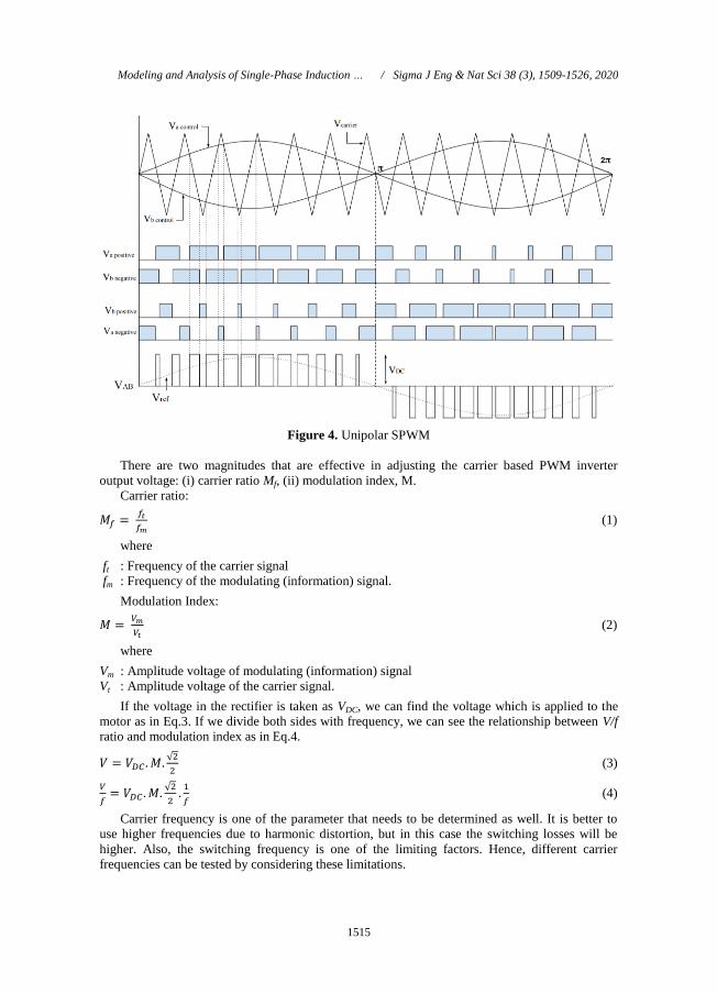
filtered easily. In Fig.4 unipolar SPWM technique is shown. In this method, a triangular
waveform is compared with a controlled sinusoidal modulating signal.
A.A. Önceler, S. Taşkın / Sigma J Eng & Nat Sci 38 (3), 1509-1526, 2020
1515
Figure 4. Unipolar SPWM
There are two magnitudes that are effective in adjusting the carrier based PWM inverter
output voltage: (i) carrier ratio Mf, (ii) modulation index, M.
Carrier ratio:
𝑀𝑓 = 𝑓𝑡
𝑓𝑚 (1)
where
ft : Frequency of the carrier signal
fm : Frequency of the modulating (information) signal.
Modulation Index:
𝑀 = 𝑉𝑚
𝑉𝑡 (2)
where
Vm : Amplitude voltage of modulating (information) signal
Vt : Amplitude voltage of the carrier signal.
If the voltage in the rectifier is taken as VDC, we can find the voltage which is applied to the
motor as in Eq.3. If we divide both sides with frequency, we can see the relationship between V/f
ratio and modulation index as in Eq.4.
𝑉 = 𝑉𝐷𝐶 . 𝑀.√2
2 (3)
𝑉
𝑓= 𝑉𝐷𝐶 . 𝑀.
√2
2.
1
𝑓 (4)
Carrier frequency is one of the parameter that needs to be determined as well. It is better to
use higher frequencies due to harmonic distortion, but in this case the switching losses will be
higher. Also, the switching frequency is one of the limiting factors. Hence, different carrier
frequencies can be tested by considering these limitations.
Modeling and Analysis of Single-Phase Induction … / Sigma J Eng & Nat Sci 38 (3), 1509-1526, 2020

1516
2.6. Simulation
The inverter model is developed on the MATLAB® Simulink® as shown in Fig. 5. Gate
signals are inverted with a logic “not gate” to prevent short circuits in DC bus.
Figure 5. The inverter model
There are four predefined type single-phase induction motor models in Simulink® which can
be connected to the inverter model. Most compressors operate with a start capacitor or start-run
capacitor. Our reference compressor has a start-run capacitor. Therefore, in this study we
consider 2 types of these models, single-phase induction motor with capacitor-start and capacitor-
start-run. The model dynamics of a single phase induction machine with squirrel-cage rotor
which has been introduced in Simulink® is shown in Fig. 6. Computation method of mechanical
system and electrical system can be examined in Mathworks® website [25].
A.A. Önceler, S. Taşkın / Sigma J Eng & Nat Sci 38 (3), 1509-1526, 2020

1517
Figure 6. Dynamics model of a single phase induction motor
2.7. Simulation Parameters
Table 3 shows the predefined motor parameters of the Simulink® and the parameters for the
selected refrigerator compressor. After implementation of these parameters to motor models, an
example simulation is run for the verification. This is an existing example which shows the
operation of a single-phase induction motor with capacitor-start and capacitor-start-run operation
modes.
Table 3. Motor parameters in Simulink®
Parameter Definition Predefined Value Compressor Value
Rs Main winding resistance 2.02 Ω 13.7 Ω
RS Auxiliary winding resistance 7.14 Ω 18.65 Ω
R′r Rotor winding resistance 4.12 Ω 15 Ω
Lms Magnetism inductance 0.1772 H 1.8 H
p Pole number 2 1
J Load inertia coefficient 0.0146 kg.m2 0.0146 kg.m2
Fr Load viscous friction coefficient. 0 0
Cs Start capacitor 254.7 µF 64 µF
Crun Run Capacitor 21 µF 5 µF
Modeling and Analysis of Single-Phase Induction … / Sigma J Eng & Nat Sci 38 (3), 1509-1526, 2020

1518
2.8. Simulation Parameter Verification
The test results of the operating performance of the compressor have been considered
according to ASHRAE standards. These data can be found on EMX80 CLT compressor data
sheet. The compressor model simulation results must be compatible with these test results. In
Table 4, the compressor power demand versus to evaporating temperature is given.
Table 4. Catalog values of the EMX80 CLT
Evaporating
Temperature
Cooling Capacity
+/- 5%
Power
+/- 5%
Current
+/- 5%
Gas Flow Rate
+/- 5%"
oC oF Btu/h kcal/h W W A kg/h
-35 -31 361 91 106 84 0.41 1.13
-30 -22 493 124 145 100 0.49 1.55
-25 -13 660 166 193 117 0.57 2.07
-20 -4 861 217 252 136 0.66 2.71
-15 5 1099 277 322 155 0.74 3.46
-10 14 1375 346 403 176 0.84 4.34
The torque applied to the motor shaft is variable in the refrigerator. It depends on the pressure
of the refrigerant gas and varies according to the amount and type of gas, the size of the condenser
and evaporator. At the same time, this torque affects the compressor power demand. In this study,
we assume that the force acting on the shaft is 0.35 Nm [28]. We also know that this value
changes according to gas flow rates. We can assume this change from 0.2 Nm to 0.5 Nm. When
the condenser temperature is 55°C, the torque on the motor shaft and evaporator temperature vary
as shown in Fig.7.
Figure 7. Shaft torque vs evaporator temperature
Simulation verification test results are shown in Fig. 8. As seen in this figure, compressor
motor model power values are compatible with the reference compressor catalog values.
A.A. Önceler, S. Taşkın / Sigma J Eng & Nat Sci 38 (3), 1509-1526, 2020

1519
Figure 8. Simulation and catalog values comparison
2.9. Carrier Frequency Determination
The most important factor in determining the carrier frequency is the output of the current
signal. In the simulation, it is necessary to draw a varying current between 0.4 A and 0.9 A as
shown in Table 4. For this type of systems, the lower the magnitude of the current causes a high
harmonic distortion. The current harmonics are observed at the constant modulation index and
constant motor frequencies while the carrier frequency ranges from 2 kHz to 8 kHz. The current
signal waveforms with the different carrier frequencies are shown in Fig. 9.
Modeling and Analysis of Single-Phase Induction … / Sigma J Eng & Nat Sci 38 (3), 1509-1526, 2020

1520
Figure 9. Motor current waveforms
As seen in these figures, higher carrier frequencies create better waveforms. However, there
can be seen that the run capacitor has a bad effect on the current waveform.
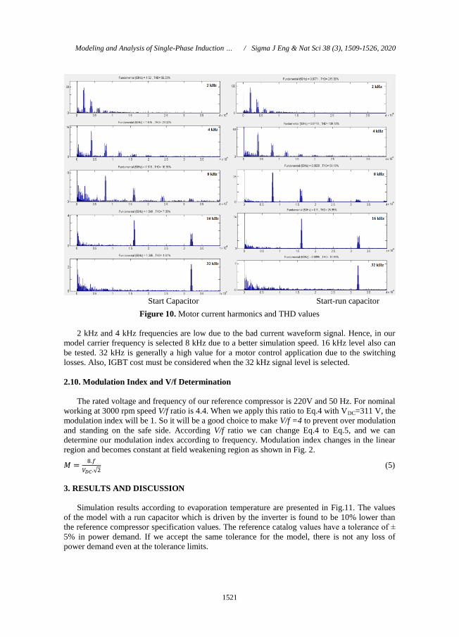
In Fig. 10, harmonics and Total Harmonic Distortion (THD) values of current are shown.
Harmonics occurred at multiples of the carrier frequencies as expected.
A.A. Önceler, S. Taşkın / Sigma J Eng & Nat Sci 38 (3), 1509-1526, 2020
1521
Start Capacitor Start-run capacitor
Figure 10. Motor current harmonics and THD values
2 kHz and 4 kHz frequencies are low due to the bad current waveform signal. Hence, in our
model carrier frequency is selected 8 kHz due to a better simulation speed. 16 kHz level also can
be tested. 32 kHz is generally a high value for a motor control application due to the switching
losses. Also, IGBT cost must be considered when the 32 kHz signal level is selected.
2.10. Modulation Index and V/f Determination
The rated voltage and frequency of our reference compressor is 220V and 50 Hz. For nominal
working at 3000 rpm speed V/f ratio is 4.4. When we apply this ratio to Eq.4 with VDC=311 V, the
modulation index will be 1. So it will be a good choice to make V/f =4 to prevent over modulation
and standing on the safe side. According V/f ratio we can change Eq.4 to Eq.5, and we can
determine our modulation index according to frequency. Modulation index changes in the linear
region and becomes constant at field weakening region as shown in Fig. 2.
𝑀 =8.𝑓
𝑉𝐷𝐶.√2 (5)
3. RESULTS AND DISCUSSION
Simulation results according to evaporation temperature are presented in Fig.11. The values
of the model with a run capacitor which is driven by the inverter is found to be 10% lower than
the reference compressor specification values. The reference catalog values have a tolerance of ±
5% in power demand. If we accept the same tolerance for the model, there is not any loss of
power demand even at the tolerance limits.
Modeling and Analysis of Single-Phase Induction … / Sigma J Eng & Nat Sci 38 (3), 1509-1526, 2020

1522
Figure 11. Power demand versus evaporator temperature
Additionally, it is necessary to compare the simulation results with another variable speed
compressor. However, as mentioned before, single-phase induction motor compressors are not
used as a variable speed compressor in refrigeration. Therefore, a variable speed three-phase
induction motor compressor is considered as a reference for comparison. We chose as a reference
VESA9C model which is manufactured by Embraco Company and is operated between 1300-
4500 rpm speeds. The catalog values of this compressor are given in Table 6.
Table 6. Catalog values of the VESA9C
Motor
Speed
+/- 5%
Cooling Capacity
+/- 5%
Power
+/- 5%
Current
+/- 5%
Gas Flow Rate
+/- 5%
Efficiency
Rate
+/- 7%
Rpm Btu/h kcal/h W W A Kg/h W/W
1300 227 57 67 39 0.32 1.49 1.73
1600 282 71 83 45 0.37 1.58 1.83
2000 356 90 104 56 0.45 1.60 1.86
3000 542 159 159 86 0.66 1.60 1.85
4500 762 192 223 131 1.00 1.47 1.71
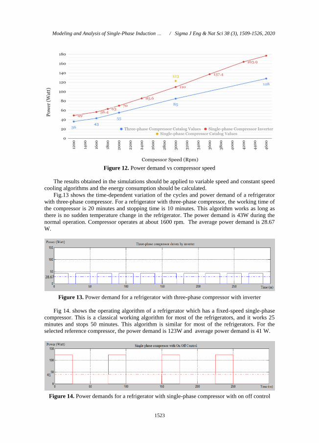
In Fig. 12, simulation results of the run capacitor which is driven by the inverter and catalog
values are compared. The power demand values of the simulation results are 25%, 30% higher
than the three-phase compressors. The difference between them also varies according to the
speed. However, it is also necessary to consider the cooling capacity when evaluating this result.
According to catalog values of compressors at 3000 rpm; while the of the single-phase
compressor (EM X80CLT) is 726 Btu/h, three-phase compressor (VESA9C) is 404 Btu/h.
Cooling capacity of the single-phase compressor has much more than three-phase compressor;
therefore, it is possible to compare them in the same algorithm.
A.A. Önceler, S. Taşkın / Sigma J Eng & Nat Sci 38 (3), 1509-1526, 2020
1523
Figure 12. Power demand vs compressor speed
The results obtained in the simulations should be applied to variable speed and constant speed
cooling algorithms and the energy consumption should be calculated.
Fig.13 shows the time-dependent variation of the cycles and power demand of a refrigerator
with three-phase compressor. For a refrigerator with three-phase compressor, the working time of
the compressor is 20 minutes and stopping time is 10 minutes. This algorithm works as long as
there is no sudden temperature change in the refrigerator. The power demand is 43W during the
normal operation. Compressor operates at about 1600 rpm. The average power demand is 28.67
W.
Figure 13. Power demand for a refrigerator with three-phase compressor with inverter
Fig 14. shows the operating algorithm of a refrigerator which has a fixed-speed single-phase
compressor. This is a classical working algorithm for most of the refrigerators, and it works 25
minutes and stops 50 minutes. This algorithm is similar for most of the refrigerators. For the
selected reference compressor, the power demand is 123W and average power demand is 41 W.
Figure 14. Power demands for a refrigerator with single-phase compressor with on off control
Modeling and Analysis of Single-Phase Induction … / Sigma J Eng & Nat Sci 38 (3), 1509-1526, 2020
1524
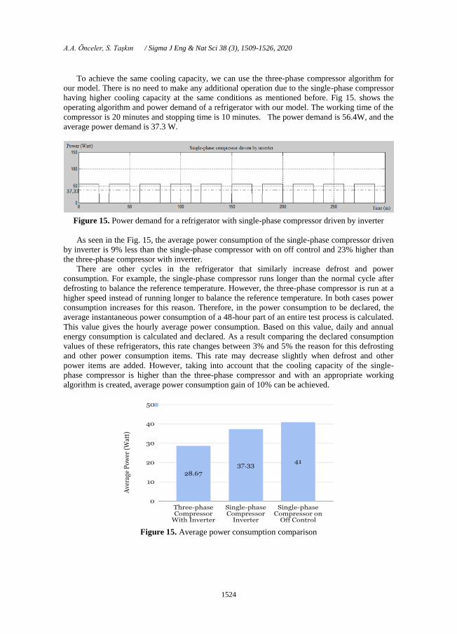
To achieve the same cooling capacity, we can use the three-phase compressor algorithm for
our model. There is no need to make any additional operation due to the single-phase compressor
having higher cooling capacity at the same conditions as mentioned before. Fig 15. shows the
operating algorithm and power demand of a refrigerator with our model. The working time of the
compressor is 20 minutes and stopping time is 10 minutes. The power demand is 56.4W, and the
average power demand is 37.3 W.
Figure 15. Power demand for a refrigerator with single-phase compressor driven by inverter
As seen in the Fig. 15, the average power consumption of the single-phase compressor driven
by inverter is 9% less than the single-phase compressor with on off control and 23% higher than
the three-phase compressor with inverter.
There are other cycles in the refrigerator that similarly increase defrost and power
consumption. For example, the single-phase compressor runs longer than the normal cycle after
defrosting to balance the reference temperature. However, the three-phase compressor is run at a
higher speed instead of running longer to balance the reference temperature. In both cases power
consumption increases for this reason. Therefore, in the power consumption to be declared, the
average instantaneous power consumption of a 48-hour part of an entire test process is calculated.
This value gives the hourly average power consumption. Based on this value, daily and annual
energy consumption is calculated and declared. As a result comparing the declared consumption
values of these refrigerators, this rate changes between 3% and 5% the reason for this defrosting
and other power consumption items. This rate may decrease slightly when defrost and other
power items are added. However, taking into account that the cooling capacity of the single-
phase compressor is higher than the three-phase compressor and with an appropriate working
algorithm is created, average power consumption gain of 10% can be achieved.
Figure 15. Average power consumption comparison
A.A. Önceler, S. Taşkın / Sigma J Eng & Nat Sci 38 (3), 1509-1526, 2020

1525
4. CONCLUSION
In this study, the refrigeration principle and cooling algorithms are examined, and developed
single-phase induction motor drive control to improve energy efficiency of a refrigerator
compressor motor. For this aim, a household refrigerator compressor parameters are considered to
obtain the model of the system. The motor parameters are set to a single-phase compressor motor
which is commonly used on the market. Hence, simulation results and real compressor catalog
values are compared and so the model is verified. The scalar control method is employed as the
control method for the compressor drive system and the corresponding carrier frequency, V/f ratio
and modulation index are also determined. While determining these values, harmonics and
harmonic distortions are also taken into consideration. Then, power consumption data of the
motor are calculated at different evaporator temperatures and at different speeds. Finally,
simulation results applied to the cooling algorithms and the energy consumptions are calculated.
Defrost system and energy consumptions of other components in the refrigerator aren’t
considered in the calculations, and the effect of the compressor on the power consumption is
examined only in normal operation condition.
Power demand of a conventional A+ refrigerator can be improved 9% with additional inverter
and properly selected working algorithm. This energy efficiency corresponds to a change from
30kWh to 40kWh per year. Also, the costs of the inverter and energy consumption improving
should be considered together. Refrigeration cycle modifications can be investigated
experimentally to determine the more reliable results. However, 9% energy efficiency does not
change the energy efficiency class of a refrigerator. For this reason, the experimental stage has not
been conducted for this study. Instead, investments can be made to increase the production of the
models with three-phase compressors which are already in use.
REFERENCES
[1] O.B. Kanargı, Evalution of the performance of a household refrigerator using a variable
speed compressor with 1D Simulations, Graduate School of Engineering and Science of
İzmir Institute of Technology, MS.c. Thesis in Mechanical Engineering, (2013), 103.
[2] V.E. Agakay, Experimental performance investigation and variable speed compressor
implementation of a household refrigerator, Graduate School of Engineering and Science
of İzmir Institute of Technology, MS.c. Thesis in Mechanical Engineering, (2013), 87.
[3] R. J. Dossat, T. J. Noran, Principles of refrigeration, Prentice Hall, (1961).
[4] ASHRAE, Handbook - Refrigeration (SI Edition). American Society of Heating,
Refrigerating and Air-Conditioning Engineers, Inc. (2006).
[5] Y.A. Çengel, M.A. Boles, Thermodynamics: An engineering approach. McGraw-Hill
Higher Education. (2005).
[6] O. Ekren, Fuzzy logic control of the compressor speed and electronic expansion valve in a
chiller, Dokuz Eylul University, Graduate School of Natural and Applied Sciences, PhD
Thesis in Mechanical Engineering, (2009), 143.
[7] T.Q. Qureshi, S.A. Tassou, Variable-speed capacity control in refrigeration systems,
Applied Thermal Engineering, 16(2), (1996), 103-113.
[8] S.A. Tassou, R.K. Green, D.R. Wilson, Energy conservation through the use of capacity
control in heat pumps, Journal of Inst. Energy, 54, (1981), 30-34.
[9] S.A. Tassou, C.J. Marquand, D.R. Wilson, The effect of capacity modulation on the
performance of vapour compression heat pump system, International Syrup. On the
Industrial Application of Heat Pumps, UK. (1982).
[10] S.A. Tassou, C.J. Marquand, Y.T. Wang, D.R. Wilson, An economic comparison of a
fixed speed, a two speed, and a variable speed vapour compression heat pump, Applied
Energy, 16, (1984), 59-66.
Modeling and Analysis of Single-Phase Induction … / Sigma J Eng & Nat Sci 38 (3), 1509-1526, 2020

1526
[11] S.A. Tassou, Experimental investigation of the dynamic performance of variable-speed
heat-pumps, Journal of Inst. Energy. 64, (1991), 95-98.
[12] K. Lida, T. Yamamoto, T. Kuroda, H. Hibi, Development of an energy saving-oriented
variable-capacity system heat-pump, ASHRAE Trans. 88, (1982), 441-449.
[13] J.A. McGovern, Performance characteristics of a reciprocating refrigerant compressor
over a range of speeds, Proceeding Purdue Compressor Technics Conference, Purdue,
(1988), 146-153.
[14] N. Ischii, M. Yamamura, H. Morokoski, M. Fukushima, S.Yamamoto, M. Sakai, On the
superior dynamic behaviour of a variable rotating speed scroll compressor, Proceeding of
Purdue Compressor Technics Conference, Purdue, (1988), 75-82.
[15] N. Ischii, M. Yamamura, S. Muramatsy, S. Yamamoto, M. Sakai, Mechanical efficiency
of a variable speed scroll compressor. Proceeding of Compressor Technics Conference,
Purdue, (1990), 192-199.
[16] C.K. Rice, Efficiency characteristics of speed-modulated drives at predicted torque
conditions for air-to-air-heat pumps. ASHRAE Trans. 94, (1988), 892 -92.
[17] C.K. Rice, Benchmark performance analysis of an ECM-Modulated air-to-air heat-pump
with a reciprocating compressor, ASHRAE Trans. 98, (1992), 430-450.
[18] H. K. Lee, G. Y. Song, J. S. Park, E. P. Hong, W. H. Jung, K.B. Park, Development of the
linear compressor for a household refrigerator, (2000). International Compressor
Engineering Conference. Paper 1364.
[19] K. Park, E. Hong, H. K. Lee, Linear motor for linear compressor, (2002). International
Compressor Engineering Conference. Paper 1544.
[20] Embraco Product Electronic Catalog
https://products.embraco.com/products/compressors,(Accessed 05.13.2018).
[21] A.S. Ba-thunya, R. Khopkar, K. Wei, H.A. Toliyat, Single-phase induction motor drives -
A Literature survey, Electric Machines and Drives Conference, (2001), Cambridge, USA,
911 – 916.
[22] B. Akin, N. Garg, Scalar (V/f) control of 3-Phase induction motors, Application Report,
(2013), Texas Instruments.
[23] A. M. Trzynadlowski, Control of induction motors, Academic Press, (2001), 228.
[24] B.K. Bose, Modern power electronics and AC drives, Prentice-Hall, (2007).
[25] Model dynamics of Single Phase Asynchronous Machine. Mathworks
https://www.mathworks.com
[26] C. Blake, C. Bull, IGBT or MOSFET: Choose Wisely, International Rectifier.
A.A. Önceler, S. Taşkın / Sigma J Eng & Nat Sci 38 (3), 1509-1526, 2020
Related Documents