Research Article Low Power OFDM Receiver Exploiting Data Sparseness and DFT Symmetry Nikos Petrellis Computer Science and Engineering Department, TEI of essaly, 41110 Larissa, Greece Correspondence should be addressed to Nikos Petrellis; [email protected] Received 14 August 2015; Revised 5 December 2015; Accepted 17 December 2015 Academic Editor: Michael Farmer Copyright © 2016 Nikos Petrellis. is is an open access article distributed under the Creative Commons Attribution License, which permits unrestricted use, distribution, and reproduction in any medium, provided the original work is properly cited. An undersampling technique appropriate for Orthogonal Frequency Division Multiplexing (OFDM) that can be implemented with low complexity hardware is presented. e OFDM receiver can operate in undersampling mode, 75% of the time. One of the advantages of the proposed scheme is the reduction down to the half of the power consumed by the Analog Digital Converter (ADC) and the Fast Fourier Transform (FFT). e FFT memory requirements for sample storage can also be reduced and its operating speed can be increased. Simulations were performed for two Quadrature Amplitude Modulation orders (16-QAM and 32-QAM), two options for the FFT size (1024 and 4096), two alternative input symbol structures for the inverse FFT (IFFT), and several sparseness levels and samples substitution options. e Symbol Error Rate (SER) and image reconstruction examples are used to show that a full reconstruction or a very low error can be achieved. Although the proposed undersampling method is evaluated for wired channel, it can also be used without any modification to wireless Single Input Single Output (SISO) systems (with an expected SER degradation). It can also be used with Multiple Input Multiple Output (MIMO) systems when an appropriate arrangement of the IFFT input symbols is adopted. 1. Introduction e OFDM is a popular modulation scheme in the contem- porary telecommunication standards (like the IEEE 802.11 and 802.15 standards). e information exchanged over the OFDM transceivers may be occasionally sparse. However, the hardware of these systems does not usually take advantage of this fact in order to reduce its power consumption and the dynamic memory requirements during the time intervals where the transferred data are sparse. In this paper, the data sparseness is defined as the fraction of the nonzero data bits ( ≪ 1). e proposed method can be used when sparse information transfer is detected in order to deactivate several power and time consuming operations and to avoid sampling some redundant input samples (by lowering the ADC sampling rate) on the receiver side. e real time adaptation of these operating features can be controlled by low complexity hardware. e sampling rate of a signal has to be at least twice as high as its higher frequency component according to the Nyquist and Shannon theorems in order to avoid distortion and information loss. Nevertheless, fewer samples can be used if the information exchanged is sparse or compressible. If for example, the information is transmitted through a high frequency carrier, there is no need to use a sampling rate twice as high as the carrier frequency at the receiver. A sampling rate comparable to the information rate can be adopted instead. A common practice is to use an analog fre- quency downconversion step that generates an intermediate frequency signal that can be sampled at a rate close to the original information rate. A popular method that can be used for the reconstruction of the original sparse data from fewer samples is the Com- pressive Sampling (or Compressed Sensing, CS for short) [1, 2]. e information recovery is based on optimization problems that can be solved by iterative procedures. e Hindawi Publishing Corporation International Journal of Distributed Sensor Networks Volume 2016, Article ID 1464639, 10 pages http://dx.doi.org/10.1155/2016/1464639

Welcome message from author
This document is posted to help you gain knowledge. Please leave a comment to let me know what you think about it! Share it to your friends and learn new things together.
Transcript

Research ArticleLow Power OFDM Receiver Exploiting Data Sparseness andDFT Symmetry
Nikos Petrellis
Computer Science and Engineering Department, TEI of Thessaly, 41110 Larissa, Greece
Correspondence should be addressed to Nikos Petrellis; [email protected]
Received 14 August 2015; Revised 5 December 2015; Accepted 17 December 2015
Academic Editor: Michael Farmer
Copyright © 2016 Nikos Petrellis.This is an open access article distributed under theCreativeCommonsAttribution License, whichpermits unrestricted use, distribution, and reproduction in any medium, provided the original work is properly cited.
An undersampling technique appropriate for Orthogonal Frequency Division Multiplexing (OFDM) that can be implementedwith low complexity hardware is presented. The OFDM receiver can operate in undersampling mode, 75% of the time. One of theadvantages of the proposed scheme is the reduction down to the half of the power consumed by theAnalogDigital Converter (ADC)and the Fast Fourier Transform (FFT). The FFT memory requirements for sample storage can also be reduced and its operatingspeed can be increased. Simulations were performed for two Quadrature Amplitude Modulation orders (16-QAM and 32-QAM),two options for the FFT size (1024 and 4096), two alternative input symbol structures for the inverse FFT (IFFT), and severalsparseness levels and samples substitution options. The Symbol Error Rate (SER) and image reconstruction examples are used toshow that a full reconstruction or a very low error can be achieved. Although the proposed undersampling method is evaluated forwired channel, it can also be used without anymodification to wireless Single Input Single Output (SISO) systems (with an expectedSER degradation). It can also be used with Multiple Input Multiple Output (MIMO) systems when an appropriate arrangement ofthe IFFT input symbols is adopted.
1. Introduction
The OFDM is a popular modulation scheme in the contem-porary telecommunication standards (like the IEEE 802.11and 802.15 standards). The information exchanged over theOFDM transceiversmay be occasionally sparse. However, thehardware of these systems does not usually take advantageof this fact in order to reduce its power consumption andthe dynamic memory requirements during the time intervalswhere the transferred data are sparse. In this paper, the datasparseness is defined as the fraction 𝑆 of the nonzero databits (𝑆 ≪ 1). The proposed method can be used whensparse information transfer is detected in order to deactivateseveral power and time consuming operations and to avoidsampling some redundant input samples (by lowering theADC sampling rate) on the receiver side. The real timeadaptation of these operating features can be controlled bylow complexity hardware.
The sampling rate of a signal has to be at least twiceas high as its higher frequency component according to theNyquist and Shannon theorems in order to avoid distortionand information loss. Nevertheless, fewer samples can beused if the information exchanged is sparse or compressible.If for example, the information is transmitted through ahigh frequency carrier, there is no need to use a samplingrate twice as high as the carrier frequency at the receiver.A sampling rate comparable to the information rate can beadopted instead. A common practice is to use an analog fre-quency downconversion step that generates an intermediatefrequency signal that can be sampled at a rate close to theoriginal information rate.
A popularmethod that can be used for the reconstructionof the original sparse data from fewer samples is the Com-pressive Sampling (or Compressed Sensing, CS for short)[1, 2]. The information recovery is based on optimizationproblems that can be solved by iterative procedures. The
Hindawi Publishing CorporationInternational Journal of Distributed Sensor NetworksVolume 2016, Article ID 1464639, 10 pageshttp://dx.doi.org/10.1155/2016/1464639

2 International Journal of Distributed Sensor Networks
proposed hardware implementations of the CS techniqueshave often been based on DSP processors [3, 4] since theresources required are high if, for example, reconfigurablehardware is employed [5]. Kalman filters [6] have also beenproposed for input signal correction and compared to CStechniques. The interpolation [7, 8] can also be viewedas a method that can reconstruct an input signal fromfewer samples. The CS techniques have been employed inOFDM environments for the use of fewer pilot symbolsand efficient bandwidth exploitation. However, no CS orother undersampling techniques have been proposed forthe reconstruction of the original data instead of the pilotinformation in OFDM systems. This is due to the fact thatthe inherent data sparseness is cancelled out in such anenvironment by the interleaving scheme, the Forward ErrorCorrection (FEC) encoding as well as the Fourier and inverseFourier transforms that are applied.
A deterministic undersampling approach that is notmodeled as an optimization problem is proposed for OFDMenvironments in [9].This approach is based on the propertiesof the Discrete Fourier Transform (DFT) and it requires (a)an appropriate interleaving/deinterleaving scheme, (b) a datasparseness detector, (c) a simple digital control of the ADCsampling rate, and (d) a digital control for the deactivation ofsome FFT operations and sample storage since several FFTbutterfly outputs are zero when the proposed undersamplingmethod operates on sparse data. The hardware circuitry thatimplements the operations (a)–(d) listed above has a lowcomplexity since there is no iterative or recursive operation.Thus, no additional latency is introduced and finally no highprecision arithmetic operations are required.
In our previous approach [9], the maximum number ofsamples (𝑅) that could be omitted and replaced by othersthat are already available is 𝑁/4, where 𝑁 is the numberof points used by the FFT and the IFFT in the OFDMtransceiver. In the current work, additional DFT propertiesare exploited in order to increase the number 𝑅 by 50%, thatis, to 3𝑁/8 without worsening the achieved BER. The newundersampling techniques introduced in this paper allowinformation recovery with low error even if the sparsenesslevel of the input data is worse. For example, in [9] when𝑅 = 𝑁/8 and 𝑆 = 2%, the achieved BER was 10−2 while theSER (which is expected to be worse than BER) falls close to10−4 here under the same conditions.Moreover, an additionalIFFT input structure is tested here; different conditions aresimulated and image reconstruction is also used as a casestudy here. The improvement in the number of omittedand replaced samples has a direct impact to the powerconsumption of the OFDM implementation since all thecritical parameters including the undersampling intervals,the number of deactivated FFT operations, and the memorystorage requirements can be improved by a similar factor.TheSER achieved can be zero in many cases or at least lower than10−3 if the input data are sparse enough and a low-orderQAMmodulation is employed.
The appropriate OFDM environment is described inSection 2 while the proposed undersampling method ispresented in Section 3. Simulation results from random input
D D DData
Systematic output
Parity bits
Output
Figure 1: The RSC encoder used.
data and image processing are presented in Section 4 for abroad channel Signal to Noise (SNR) range, a number ofdifferent 𝑅 values, various sparseness levels, QAM orders andFFT sizes.
2. OFDM Transceiver Description
The input data stream at the OFDM transmitter is initiallyencoded in order to apply an efficient FEC decoding algo-rithmon the receiver side and correct the potential errors thatwill occur during the data transfer. The encoder is usually aRecursive Systematic Convolutional (RSC) encoder like theone presented in Figure 1. Such an encoder is characterizedby a forward path (described by the polynomial 1 + 𝐷 +𝐷2
+ 𝐷3) and a feedback path (described by the polynomial
1 + 𝐷 + 𝐷2). The systematic output is connected directly to
the input while the second output generates the parity bits.The parity bits are the necessary redundant information thathas to be transmitted along with the original data for theerror correction of as many errors as possible on the receiverside without the need of packet retransmission. The switchat the encoder outputs selects the current bit (either dataor parity) that will drive the next transmitter stage, that is,the 𝑞-QAM modulator. A usual practice is to transmit in analternative manner one data and one parity bit. However,a small buffering of a few bits (log
2
(𝑞)) is necessary in theproposedmethod since log
2
(𝑞) data or parity bits aremappedto a single QAM symbol.
The order of the forward and feedback encoder polyno-mials defines theminimumTrellis decoding diagram that willbe needed on the receiver side in order to achieve an efficientcorrection scheme [10]. Taking into consideration that theinput bit stream is sparse, the systematic data output of theencoder has a predictable value which is usually “0.” Theparity output of an encoder like the one shown in Figure 1is also “0” until the first “1” appears at the input. However, thefeedback path of the encoder makes the effect of a single “1”at the input permanent at the parity output of the encoder.
In this paper, the fact that most of the initial parity outputbits in a data packet have zero value since the first “1” atthe data input may delay to appear is exploited first. If theinput sparseness level is 𝑆 (𝑆 < 1), that is, if the fraction ofnonzero values is 𝑆 in an input data packet, then the first “1”will statistically appear at the position 1/𝑆. For example, if thelength of the input data packet is 1536 and 𝑆 = 0.01 (or 1%),then 1536 ⋅ 0.01 ≈ 15 ones are expected to appear within thispacket. If it is assumed that these 1’s are uniformly scattered,then the first of them is expected to appear approximately

International Journal of Distributed Sensor Networks 3
Padding Padding192 symbols 192 symbols 192 symbols 192 symbols
0 96 289 480 673 867 1023
p p p p
pilt
data
par
data
par
data
par
pilt
data
par
data
data
par
par
pilt
data
par
data
par
data
par
pilt
data
par
data
data
par
par
Segment 3:192 16-QAM symbols
Segment 2:192 16-QAM symbols
Segment 1:192 16-QAM symbols
Segment 4:192 16-QAM symbols
· · · · · · · · · · · ·
(a)
PaddingPadding 192 symbols 192 symbols 192 symbols
0 192 385 2894 3087 3280 4095
p p p p
Segment 1:192 32-QAM symbols
pilt
data
par
data
par
data
par
pilt
data
par
data
data
par
par
pilt
data
par
data
par
data
par
pilt
data
par
data
data
par
par
Segment 2:192 16-QAM symbols
Segment 15:192 16-QAM symbols
Segment 16:192 16-QAM symbols
· · · · · · · · · · · ·
192 symbols
· · ·
(b)
0 N/4 N/2 3N/4
Dat
a
Parit
y Α
D
ata
Parit
y B
Dat
aPa
rity
Α
Dat
aPa
rity
B D
ata
Parit
y B
Dat
aPa
rity
A
Dat
aPa
rity
BD
ata
Parit
y A
Dat
aPa
rity
Α
Dat
aPa
rity
B
Dat
aPa
rity
Α
Dat
aPa
rity
B D
ata
Parit
y B
Dat
aPa
rity
A
Dat
aPa
rity
BD
ata
Parit
y A
......
......
N − 1
(c)
Figure 2: IFFT input packet structure for𝑁 = 1024 (a) and𝑁 = 4096 (b). Symbols “pilt” and “par” stand for pilot and parity QAM symbols,respectively. IFFT input packet structure appropriate for parity prediction (c).
at the position 1536/15 ≈ 102 which is equal to 1/𝑆. Thisexample is simply used in order to show that if the first “1”delays to appear in a data packet, then the parity bits at theFEC encoder output will remain 0 for a long time interval.More specifically, the parity bits that correspond to the first102 data bits with value 0 will also be zero (assuming ofcourse that the FEC encoder is reset at the beginning of eachpacket transmission). Smarter parity bit pattern predictionsare also employed since the same parity pattern is generatedrepeatedly by the FEC encoder between two consecutiveappearances of “1” at its input. For example, after the first “1”at the input of the FEC encoder of Figure 1, the parity outputgenerates the repeating pattern “1001110.”
At the next stage, the 𝑞-QAM takes place and log2
(𝑞) bitsare mapped to a 𝑞-QAM symbol. The parity and data bits areQAMmodulated separately producing data QAM and parityQAM symbols. Most of the data QAM symbols will have anidentical value 𝑋
𝑐
. However, several parity QAM symbolsgenerated at the beginning of a data packet encoding will alsohave the same value. Pad and Pilot symbols will also be addedor merged with the data and parity QAM symbols to form
the input of the IFFT (symbols 𝑋𝑘
, 0 ≤ 𝑘 < 𝑁) that has totake place on the OFDM transmitter side. A Serial to Parallelconverter can group the 𝑁, 𝑋
𝑘
symbols before the IFFT isapplied. As will be explained in the next section, it is desirableto have as many identical values at the odd positions of theIFFT input as possible. For this reason, the IFFT input canhave the forms presented in Figure 2 for two IFFT/FFT sizes:𝑁 = 1024 and 𝑁 = 4096. Four pilots have been used with𝑁 = 1024 and sixteen with𝑁 = 4096. The value selected forthe pad and pilot symbols is equal to 𝑋
𝑐
. The placement ofthe various symbols in Figures 2(a) and 2(b) is performed insuch a way that the odd positions of the IFFT input are filledwith data, pilot, or pad QAM symbols. In order to achievethis goal, the order of the parity and data QAM symbols isreversed after subsequent pilots. An appropriate IFFT inputstructure that can be used by the extended undersamplingmethod described in the next section appears in Figure 2(c).The pilot or pad symbols can be placed either in the positionof the data or the parity symbols. If the value of a pilot or padsymbol is selected to be equal to the predicted data or parityone, the error rate will not be significantly affected.

4 International Journal of Distributed Sensor Networks
The required interleaving can be performed before theIFFT, as bit interleaving between data bits only and paritybits only. Channel interleaving can also be performed bypermuting data or parity QAM symbols as long as they arefinally placed in odd and even positions, respectively.
The IFFT output symbols 𝑥𝑛
(0 ≤ 𝑛 < 𝑁) are serializedby a Parallel to Serial module while a Cyclic Prefix (CP)is transmitted before these IFFT output symbols in orderto avoid intersymbol interference. The IFFT output and theCP are serially transmitted over the communication channelafter their value is converted to an analog signal by a Digitalto Analog Converter (DAC). The channel is assumed tobe an Additive White Gaussian Noise (AWGN) channelwhich is appropriate for wired communications. However,the proposed architecture can be directly used in wirelessenvironments too, with a single transmitter and a singlereceiver (SISO). Extensions of this architecture could also beemployed in MIMO environments, but different IFFT inputstructures than the ones presented in Figure 2 may have tobe selected to exploit Fourier properties when for instanceantenna diversity is used. This is part of our on-going work.
The reverse procedure has to take place on the receiverside. A pair of ADCs can provide, through a Serial to Parallelmodule, the 𝑁 digitized complex values that form the inputof the FFT. In the case where no errors occur, the FFT outputis the set of 𝑋
𝑘
, 𝑞-QAM symbols. These 𝑞-QAM symbolsare transformed to a symbol stream by a Parallel to Serialconverter and then they are deinterleaved and assigned toa sequence of data and parity bits that are decoded by anappropriate FECmethod like Viterbi, LDPC, Turbo Decoder,and so forth.
Except for the interleaving and the QAM symbol place-ment scheme that has already been described, the ADCand FFT stages of the receiver have also to be modified inthe current OFDM framework. More specifically, the ADCsampling should be controlled by a simple digital circuitthat will lower the sampling rate at predetermined timeintervals when sparse data are detected at the input. Asimple frequency divider like a flip flop can be employed tocontrol the sampling rate of the ADC, since, for example, thesampling rate can be reduced to the half in the undersamplingintervals if 𝑁/4 or 3𝑁/8 samples are substituted as willbe described in the next section. If an ADC operates atthe half sampling frequency the power consumed by theADC is also expected to be reduced to the half [11]. Thesamples that have been omitted by the ADC sampling whenit operates in lower rate are substituted by other alreadyavailable samples that are expected to have the same value andcan be temporarily stored in a buffer.The sparse data detectoron the receiver side can be based on counting zeros in aframe payload after the FEC decoder. If the number of zerosis higher than a threshold the receiver recognizes a sparsedata transmission and enters the undersampling mode. Theend of the sparse data transmission can be detected at ahigher network layer (like the transport layer) when a largenumber of errors are detected. In this case, the receiverexits the undersampling mode. The sparse data detector willalso control the deactivation of specific FFT operations asdescribed in [9].
3. The Undersampling Procedure
The DFT and the inverse DFT transforms are defined by thefollowing equations, respectively,
𝑋𝑘
=
𝑁−1
∑
𝑛=0
𝑥𝑛
𝑒−𝑖2𝜋𝑘𝑛/𝑁
, 0 ≤ 𝑘 < 𝑁 − 1, (1)
𝑥𝑛
=1
𝑁
𝑁−1
∑
𝑘=0
𝑋𝑘
𝑒𝑖2𝜋𝑘𝑛/𝑁
, 0 ≤ 𝑛 < 𝑁 − 1. (2)
The undersampling policy followed in [9] has been basedon the fact that the products for odd 𝑘 (𝑘 < 𝑁/2) and 𝑘+𝑁/2in (1) sum up to the same result in both 𝑥
𝑛
and 𝑥𝑛+𝑁/2
if 𝑛 isalso odd:
𝑥𝑛
=
𝑁−1
∑
𝑘=0
𝑋𝑘
𝑒𝑖(2𝜋/𝑁)𝑘𝑛
= ∑
𝑘=0,2,...,𝑁−2
𝑋𝑘
𝑒𝑖(2𝜋/𝑁)𝑘𝑛
+ ∑
𝑘=1,3,...,𝑁/2−1
(𝑋𝑘
𝑒𝑖(2𝜋/𝑁)𝑘𝑛
+ 𝑋𝑘+𝑁/2
𝑒𝑖(2𝜋/𝑁)(𝑘+𝑁/2)𝑛
) = ∑
𝑘=0,2,...,𝑁−2
𝑋𝑘
𝑒𝑖(2𝜋/𝑁)𝑘𝑛
+ ∑
𝑘=1,3,...,𝑁/2−1
(𝑋𝑘
− 𝑋𝑘+𝑁/2
) 𝑒𝑖(2𝜋/𝑁)𝑘𝑛
,
(3)
𝑥𝑛+𝑁/2
=
𝑁−1
∑
𝑘=0
𝑋𝑘
𝑒𝑖(2𝜋/𝑁)𝑘(𝑛+𝑁/2)
=
𝑁−1
∑
𝑘=0
𝑋𝑘
𝑒𝑖(2𝜋/𝑁)𝑘𝑛
𝑒𝑖(2𝜋/𝑁)𝑘(𝑁/2)
=
𝑁−1
∑
𝑘=0
𝑋𝑘
𝑒𝑖(2𝜋/𝑁)𝑘𝑛
(−1)𝑘
= ∑
𝑘=0,2,...,𝑁−2
𝑋𝑘
𝑒𝑖(2𝜋/𝑁)𝑘𝑛
− ∑
𝑘=1,3,...,𝑁/2−1
(𝑋𝑘
𝑒𝑖(2𝜋/𝑁)𝑘𝑛
+ 𝑋𝑘+𝑁/2
𝑒𝑖(2𝜋/𝑁)(𝑘+𝑁/2)𝑛
) = ∑
𝑘=0,2,...,𝑁−2
𝑋𝑘
𝑒𝑖(2𝜋/𝑁)𝑘𝑛
− ∑
𝑘=1,...,𝑁/2−1
(𝑋𝑘
− 𝑋𝑘+𝑁/2
) 𝑒𝑖(2𝜋/𝑁)𝑘𝑛
.
(4)
As can be seen, both (3) and (4) consist of a common term(the sum of the even 𝑘’s) and a sum of differences for the odd𝑘’s. If𝑋
𝑘
= 𝑋𝑘+𝑁/2
, then the second sum at (3) and (4) equals0 and 𝑥
𝑛
= 𝑥𝑛+𝑁/2
for odd 𝑛 values.This is why the structuresof the IFFT input packets displayed in Figures 2(a) and 2(b)have been selected trying to place 𝑋
𝑘
= 𝑋𝑐
values at the odd𝑘-positions. In this case, 𝑅 of 𝑁, 𝑥
𝑛
values, where 𝑅 is up to𝑁/4 (half of the 𝑥
𝑛
symbols with odd 𝑛) can be substituted byothers. 𝑥
𝑛
symbols that will be used to substitute others canbe copied directly by the Serial to Parallel module at the FFTinput. For example, the 𝑥
𝑛+𝑁/2
values with odd 𝑛 and 𝑛 < 𝑁/2can be replaced by 𝑥
𝑛
. Although the number of symbols usedby the FFTon the receiver side is always𝑁, large parts of these

International Journal of Distributed Sensor Networks 5
symbols are copies of others and do not need to be supplied bythe ADC.Thus, the undersampling term used so far refers tothe number of samples generated by the ADC that are lowerthan those determined by the Nyquist theorem. Of course,𝑋𝑘
= 𝑋𝑘+𝑁/2
for some odd 𝑘 values since the input data aresparse but not zero and thus𝑋
𝑘
= 𝑋𝑐
in these cases. As will beshown in the next section if 𝑅 = 𝑁/4 then the achieved SERhas an unacceptable error floor. However, if𝑅 = 𝑁/8 or lowerand the sparseness level 𝑆 is also low enough (below 1%), agood SER or even a full reconstruction can be performed.
In order to achieve an acceptable SER with higher 𝑅values, other DFT properties are also exploited in this paper.If we focus on 𝑥
𝑛
and 𝑥𝑁/2−𝑛
with odd 𝑛 and 𝑛 < 𝑁/4, (1) canbe rewritten as
𝑥𝑛
= ∑
𝑘=1,3,...,𝑁/4
(𝑋𝑘
𝑒𝑖(2𝜋/𝑁)𝑘𝑛
+ 𝑋𝑁/2−𝑘
𝑒𝑖(2𝜋/𝑁)𝑛(𝑁/2−𝑘)
)
+ ∑
𝑘=1,3,...,𝑁/4
(𝑋𝑘+𝑁/2
𝑒𝑖(2𝜋/𝑁)(𝑘+𝑁/2)𝑛
+ 𝑋𝑁−𝑘
𝑒𝑖(2𝜋/𝑁)𝑛(𝑁−𝑘)
) + ∑
𝑘=2,...,𝑁/2−2
(𝑋𝑘
𝑒𝑖(2𝜋/𝑁)𝑘𝑛
+ 𝑋𝑁−𝑘
𝑒𝑖(2𝜋/𝑁)(𝑁−𝑘)𝑛
) + 𝑋0
− 𝑋𝑁/2
,
(5)
where the first sum adds, in pairs,𝑋𝑘
at odd positions that aresymmetric around 𝑁/4, the second sum adds the 𝑋
𝑘
pairswith odd 𝑘, that are symmetric around 3𝑁/4, and the lastsum adds the𝑋
𝑘
pairs with even 𝑘, that are symmetric around𝑁/2.
Aftermanipulating the exponents and taking into consid-eration the fact that 𝑛 is odd everywhere while the 𝑘 is eitherodd or even according to the specific sum that it is used in,(5) can be rewritten as
𝑥𝑛
= ∑
𝑘=1,3,...,𝑁/4
(𝑋𝑘
𝑒𝑖(2𝜋/𝑁)𝑘𝑛
− 𝑋𝑁/2−𝑘
𝑒−𝑖(2𝜋/𝑁)𝑘𝑛
)
+ ∑
𝑘=1,3,...,𝑁/4
(−𝑋𝑘+𝑁/2
𝑒𝑖(2𝜋/𝑁)𝑘𝑛
+ 𝑋𝑁−𝑘
𝑒−𝑖(2𝜋/𝑁)𝑘𝑛
)
+ ∑
𝑘=2,...,𝑁/2−2
(𝑋𝑘
𝑒𝑖(2𝜋/𝑁)𝑘𝑛
+ 𝑋𝑁−𝑘
𝑒−𝑖(2𝜋/𝑁)𝑘𝑛
)
+ 𝑋0
− 𝑋𝑁/2
.
(6)
In the same way, 𝑥𝑁/2−𝑛
can be expressed as
𝑥𝑁/2−𝑛
= ∑
𝑘=1,3,...,𝑁/4
(−𝑋𝑘
𝑒−𝑖(2𝜋/𝑁)𝑘𝑛
+ 𝑋𝑁/2−𝑘
𝑒𝑖(2𝜋/𝑁)𝑘𝑛
)
+ ∑
𝑘=1,3,...,𝑁/4
(𝑋𝑘+𝑁/2
𝑒−𝑖(2𝜋/𝑁)𝑘𝑛
− 𝑋𝑁−𝑘
𝑒𝑖(2𝜋/𝑁)𝑘𝑛
)
+ ∑
𝑘=0,2,...,𝑁/2
(𝑋𝑘
𝑒−𝑖(2𝜋/𝑁)𝑘𝑛
+ 𝑋𝑁−𝑘
𝑒𝑖(2𝜋/𝑁)𝑘𝑛
) + 𝑋0
+ 𝑋𝑁/2
.
(7)
As can be seen when (6) and (7) are compared, IFFToutputs 𝑥
𝑛
and 𝑥𝑁/2−𝑛
are equal, if 𝑋𝑘
= 𝑋𝑁/2−𝑘
(with odd𝑘 and 𝑘 lower than 𝑁/4), 𝑋
𝑘+𝑁/2
= 𝑋𝑁−𝑘
(with odd 𝑘 and𝑁/2 < 𝑘 < 3𝑁/4), and 𝑋
𝑘
= 𝑋𝑁−𝑘
, with 𝑘 being even and0 ≤ 𝑘 < 𝑁/2. In other words, 𝑥
𝑛
= 𝑥𝑁/2−𝑛
if the followingconditions hold: (a)𝑋
𝑘
symbol pairs at odd positions that aresymmetric around𝑁/4 are equal, (b)𝑋
𝑘
pairs with odd 𝑘 thatare symmetric around 3𝑁/4 are equal, and (c) 𝑋
𝑘
pairs witheven 𝑘 that are symmetric around𝑁/2 are also equal.
This has been proven for odd 𝑛 values that are lowerthan 𝑁/2 but can also be proved in a similar manner for𝑥𝑛
and 𝑥𝑁−𝑛
, where 𝑛 is again odd and 𝑁/2 < 𝑛 < 3𝑁/4.The conditions (a) and (b) defined above hold for most ofthe symbol pairs in Figures 2(a) and 2(b), since data QAMsymbols have been stored in the odd positions. It cannot beguaranteed though thatmost of the even positioned pairs willhave identical samples since these are parity symbols.The factthat the initial parity symbols in a packet have also the samevalue 𝑋
𝑐
as discussed in the previous section is used in thiswork in order to allow the substitution of additional samplesat the receiver FFT. The fact that a parity pattern is repeatedbetween successive 1’s at the FEC encoder sparse input isexploited by the IFFT input structure shown in Figure 2(c)in order to reassure that the condition (c) is valid for moresymbol pairs and thus a lower error can be achieved.
The undersampling interval can be extended using theprevious conditions (a)–(c) as shown in Figure 3. Figure 3(a)shows that up to 𝑁/4 samples could have been substitutedin [9]. More specifically, the sample 𝑥
𝑁/2+𝑛
(𝑛 is odd) couldhave been omitted by the sampling procedure on the receiverside and its value could have been retrieved by 𝑥
𝑛
. Now, thevalue of 𝑥
𝑁/2−𝑛
can also be considered to be replaced by 𝑥𝑛
as shown in Figure 3. Consequently, the sampling intervalcan be extended by 50%. Fewer samples can be replaced ifa better SER should be achieved, but the tradeoff betweenthe substituted samples 𝑅 and the achieved SER is still betterthan using the sampling interval shown in Figure 3(a) aswill be shown in the following section. Fewer samples canbe replaced if the ones that are omitted are selected with adistance of 4 or 8 instead of 2. For example, if the dashed linesof Figure 3(b) are not used then samples at a distance of 4 areselected for substitution.
4. Simulation Results
The sample substitution policy is initially evaluated on rawdata with various degrees of sparseness. In the simulationsinitially presented, a data bit stream is mapped to QAMsymbols that form the input of an𝑁-point IFFT. The samplesubstitution policy is applied to the output of the IFFT andthe resulting set of data forms the input of an 𝑁-point FFTtransform in order to reconstruct the initial QAM symbolsand estimate the SER of this process. In this setup, the onlyerror sources are the sample substitution process and theAWGN noise. The AWGN is expressed as the channel SNRin Figures 4–6. The truncation error of the real numbers isnot taken into consideration and a perfect synchronization isassumed between the receiver and the transmitter.

6 International Journal of Distributed Sensor Networks
Undersampling rateFull sampling rate
N FFT inputs
1 3 5 N/2 + 1 N/2 + 3 N/2 + 5· · · · · ·
(a)
N FFT inputs
Undersampling rateFull sampling rate
1 3 5 N/2 − 3 N/2 − 1 N/2 + 1 N/2 + 3 N/2 + 5· · · · · ·
(b)
Figure 3: Undersampling intervals applied in [9] (a) and the extended undersampling interval used in this work (b).
SER
100
10−1
10−2
10−3
10−4
10−5
10−6
0 10 20 30 40 50 60 70 80SNR (dB)
3N/16
3N/32
3N/64
N/4
N/8
N/16
N/32
SER versus SNR, sparseness = 0.5%, 16-QAM, N = 1024, no FEC
(a)
SER
100
10−1
10−2
10−3
10−4
10−5
0 10 20 30 40 50 60 70 80SNR (dB)
3N/16
3N/32
3N/64
N/4
N/8
N/16
N/32
SER versus SNR, sparseness = 0.5%, 32-QAM,N = 4096, no FEC
(b)
Figure 4: 𝑆 = 0.5% for𝑁 = 1024/16-QAM (a) and𝑁 = 4096/32-QAM (b).
The IFFT input structures used are the ones shown inFigures 2(a) and 2(b). The sample substitution policies testedinclude 𝑅 = 3𝑁/16, 𝑅 = 3𝑁/32, and 𝑅 = 3𝑁/64 for thenew method proposed in this paper and 𝑅 = 𝑁/4, 𝑅 = 𝑁/8,𝑅 = 𝑁/16, and 𝑅 = 𝑁/32 for the policy followed in [9].
As can be seen from Figures 4–6, there are severalcases where the new substitution policy achieves better SERalthough the number of samples replaced is higher. Forexample, in Figure 4(b), the case where 𝑅 = 𝑁/32 shows aworse SER compared to the case of 𝑅 = 3𝑁/64, althoughthe number of samples replaced in the latter case is higherby 𝑁/64. The SER is worse for higher-order QAM. Thisstems from the fact that when more bits are mapped to asingle QAM symbol, there is a higher probability that this
symbol has been derived from bit combinations that contain1’s and thus its value will not be equal to𝑋
𝑐
. If the sparsenesslevel is 1% or lower, there are several 𝑅 values that generateacceptable SER.More specifically, for𝑅 ≤ 3𝑁/64, a full signalreconstruction can be performed in 𝑁 = 1024/16-QAMcombination for any sparseness level tested. For 𝑅 > 𝑁/16,the SER is not acceptable in most of the cases (SER > 10−2).
In the new sample replacement policy, the SER is lowerdespite the fact that a higher number of 𝑅 samples aresubstituted and this holds only when no FEC. If FECmethodis employed (Viterbi) in order to emulate a full OFDMenvironment, the SER of the new method is much worseas can be seen from Figure 7 because it has been assumedthat the parity QAM symbols have also the same value, 𝑋
𝑐
.

International Journal of Distributed Sensor Networks 7
0 10 20 30 40 50 60 70 80SNR (dB)
SER
100
10−1
10−2
10−3
10−4
10−5
3N/16
3N/32
3N/64
N/4
N/8
N/16
N/32
SER versus SNR, sparseness = 1%, 16-QAM, N = 1024, no FEC
(a)
0 10 20 30 40 50 60 70 80SNR (dB)
SER
100
10−1
10−2
10−3
10−4
3N/16
3N/32
3N/64
N/4
N/8
N/16
N/32
SER versus SNR, sparseness = 1%, 32-QAM, N = 4096, no FEC
(b)
Figure 5: 𝑆 = 1%,𝑁 = 1024/16-QAM (a) and𝑁 = 4096/32-QAM (b).
SER
100
10−1
10−2
10−3
10−4
10−5
10−6
0 10 20 30 40 50 60 70 80SNR (dB)
3N/16
3N/32
3N/64
N/4
N/8
N/16
N/32
SER versus SNR, sparseness = 2%, 16-QAM, N = 1024, no FEC
(a)
SER
100
10−1
10−2
10−3
0 10 20 30 40 50 60 70 80SNR (dB)
3N/16
3N/32
3N/64
N/4
N/8
N/16
N/32
SER versus SNR, sparseness = 2%, 32-QAM, N = 4096, no FEC
(b)
Figure 6: 𝑆 = 2%,𝑁 = 1024/16-QAM (a) and𝑁 = 4096/32-QAM (b).
The SER can be improved if an FEC encoder with data ratehigher than 1/2 is used, since most of the IFFT input framepositions will be allocated to data symbols. Moreover, theparity pattern prediction employed in Figure 2(c) allows theplacement of identical symmetric parity symbols to complywith the condition (c) defined in Section 3.
The last case study concerns the reconstruction (Figures8–11) within an OFDM environment of two images. Theoriginal first image (A) is shown in Figure 8(a), and thereconstructed images using as IFFT input structure the oneshown in Figure 2(a) appear in Figures 8(b), 8(c), and 9. TheMean Square Error (MSE) and NormalizedMSE (NMSE) arelisted in each case. The best NMSE = 0.085 is achieved when𝑁/32 samples are substituted with the old undersamplingmethod [9]. When 3𝑁/64 samples are substituted with the
proposed method, NMSE is 0.109. It is interesting to noticethat when 𝑅 = 3𝑁/32 samples are replaced by the newundersampling method, the NMSE is 0.17 when FEC is usedand falls below 0.125 when the FEC is deactivated.
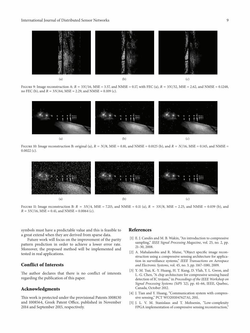
The original second image (B) is shown in Figure 10(a),while the reconstructed images are shown in Figures 10(b),10(c), and 11. In the reconstruction of the second image, theViterbi FEC decoding is used in all cases and the IFFT inputstructure shown in Figure 2(c) is employed. The exploitationof the advanced parity pattern predictability of this IFFTinput structure leads to better MSE/NMSE results as can beseen by comparing, for example, the NMSE errors in thecommon cases between images A and B: 𝑅 = 𝑁/16 and𝑅 = 3𝑁/16. With𝑅 = 𝑁/16, the NMSE in the reconstructionof images A and B is 0.105 and 0.0022, respectively. With

8 International Journal of Distributed Sensor NetworksSE
R
100
10−1
10−2
10−3
10−4
10−5
10−6
0 10 20 30 40 50 60 70 80SNR (dB)
3N/16
3N/32
3N/64
N/4
N/8
N/16
N/32
SER versus SNR, sparseness = 1%, 16-QAM, N = 1024, Viterbi FEC
(a)
0 10 20 30 40 50 60 70 80SNR (dB)
SER
100
10−1
10−2
10−3
10−4
10−5
3N/16
3N/32
3N/64
N/4
N/8
N/16
N/32
SER versus SNR, sparseness = 1%, 32-QAM, N = 4096, Viterbi FEC
(b)
Figure 7: 𝑆 = 1%, Viterbi FEC applied,𝑁 = 1024/16-QAM (a) and𝑁 = 4096/32-QAM (b).
(a) (b) (c)
Figure 8: Image reconstruction A: original (a), 𝑅 = 𝑁/16, MSE = 2.21, and NMSE = 0.105 (b), 𝑅 = 𝑁/32, andMSE = 1.78, and NMSE = 0.085(c).
𝑅 = 3𝑁/16, the NMSE in the reconstruction of images Aand B is 0.17 and 0.0064, respectively. A good quality imagereconstruction can be achieved in Figures 10 and 11 even if ahigher number of samples are omitted by the undersamplingprocess (e.g., 𝑅 = 𝑁/8 and 𝑅 = 3𝑁/16).
In [2], a CS approach for surveillance applications isdescribed showing NMSE higher than 0.11. In [6], the pro-posed Kalman filter for slowly changing sparse input patternsis compared to regularCS approaches achieving in some casesMSE lower than 0.21 and in some others an MSE between 10and 22.TheMSE in [8] is measured in dB and shows an errorfloor of −15 dB when the channel SNR is higher than 20 dB.
The number of samples required for the input signalreconstruction by the referenced approaches is smaller thanthe ones required by the proposed method. Nevertheless,complicated hardware is needed in order to solve the opti-mization problems used in these approaches. Although thenumber of samples required by the proposed undersamplingmethod has been reduced in this paper concerning [9], it isstill relatively high. However, it can be implementedwith verylow complexity hardware since no optimization problems anditerative processes are used. Moreover, no additional delay is
introduced due to the noniterative nature of the proposedprocedure. On the contrary, the FFT has been acceleratedsince many of its butterflies or operations can be deactivatedwhen sparse data are used. Significant reduction can also beachieved in this way in the power and memory requirementsof the final system.
5. Conclusions
An undersampling method that can be used in a wired orwireless OFDM environment was presented in this paper.It can reduce the samples needed at the receiver by up to3/8. It can be implemented with very low complexity/costhardware, while a significant power reduction (up to 1/2) canbe achieved since the ADC at the receiver can slow downits sampling rate for up to 3/4 of the time. The simulationresults showed that a better SER can be achieved, using theundersamplingmethod proposed in this work in comparisonwith the method proposed in the past by the authors,although a higher number of samples can be substituted byothers. In order to achieve this improvement, the parityQAM
International Journal of Distributed Sensor Networks 9
(a) (b) (c)
Figure 9: Image reconstruction A: 𝑅 = 3𝑁/16, MSE = 3.57, and NMSE = 0.17, with FEC (a), 𝑅 = 3𝑁/32, MSE = 2.62, and NMSE = 0.1248,no FEC (b), and 𝑅 = 3𝑁/64, MSE = 2.29, and NMSE = 0.109 (c).
(a) (b) (c)
Figure 10: Image reconstruction B: original (a), 𝑅 = 𝑁/8, MSE = 0.81, and NMSE = 0.0125 (b), and 𝑅 = 𝑁/16, MSE = 0.145, and NMSE =0.0022 (c).
(a) (b) (c)
Figure 11: Image reconstruction B: 𝑅 = 3𝑁/4, MSE = 7.215, and NMSE = 0.11 (a), 𝑅 = 3𝑁/8, MSE = 2.25, and NMSE = 0.039 (b), and𝑅 = 3𝑁/16, MSE = 0.41, and NMSE = 0.0064 (c).
symbols must have a predictable value and this is feasible toa great extend when they are derived from sparse data.
Future work will focus on the improvement of the paritypattern prediction in order to achieve a lower error rate.Moreover, the proposed method will be implemented andtested in real applications.
Conflict of Interests
The author declares that there is no conflict of interestsregarding the publication of this paper.
Acknowledgments
This work is protected under the provisional Patents 1008130and 1008564, Greek Patent Office, published in November2014 and September 2015, respectively.
References
[1] E. J. Candes and M. B. Wakin, “An introduction to compressivesampling,” IEEE Signal Processing Magazine, vol. 25, no. 2, pp.21–30, 2008.
[2] A. Mahalanobis and R. Muise, “Object specific image recon-struction using a compressive sensing architecture for applica-tion in surveillance systems,” IEEE Transactions on Aerospaceand Electronic Systems, vol. 45, no. 3, pp. 1167–1180, 2009.
[3] Y.-M. Tsai, K.-Y. Huang, H. T. Kung, D. Vlah, Y. L. Gwon, andL.-G. Chen, “A chip architecture for compressive sensing baseddetection of IC trojans,” in Proceedings of the IEEEWorkshop onSignal Processing Systems (SiPS ’12), pp. 61–66, IEEE, Quebec,Canada, October 2012.
[4] J. Tian and Y. Huang, “Communication system with compres-sive sensing,” PCTWO2011047627A1, 2011.
[5] J. L. V. M. Stanislaus and T. Mohsenin, “Low-complexityFPGA implementation of compressive sensing reconstruction,”

10 International Journal of Distributed Sensor Networks
in Proceedings of the International Conference on Computing,Networking and Communications (ICNC ’13), pp. 671–675, SanDiego, Calif, USA, January 2013.
[6] N. Vaswani, “Kalman filtered compressed sensing,” in Pro-ceedings of the 15th IEEE International Conference on ImageProcessing (ICIP ’08), pp. 893–896, IEEE, SanDiego, Calif, USA,October 2008.
[7] S. A. Dyer and J. S. Dyer, “Cubic-spline interpolation. 1,” IEEEInstrumentation &Measurement Magazine, vol. 4, no. 1, pp. 44–46, 2011.
[8] T. E. Tuncer, “Block-based methods for the reconstruction offinite-length signals from nonuniform samples,” IEEE Transac-tions on Signal Processing, vol. 55, no. 2, pp. 530–541, 2007.
[9] N. Petrellis, “Under-sampling in OFDM telecommunicationsystems,” Applied Sciences, vol. 4, no. 1, pp. 79–98, 2014.
[10] C. Pimentel, R. D. Souza, B. F. Uchoa-Filho, and I. Benchi-mol, “Minimal trellis for systematic recursive convolutionalencoders,” in Proceedings of the IEEE International Symposiumon Information Theory Proceedings (ISIT ’11), pp. 2477–2481,IEEE, Saint Petersburg, Russia, August 2011.
[11] P. Poshalla, “Why oversampling when undersampling can dothe job,” Texas Instruments Application Report SLAA594A,2013, http://www.ti.com/lit/an/slaa594a/slaa594a.pdf.

International Journal of
AerospaceEngineeringHindawi Publishing Corporationhttp://www.hindawi.com Volume 2014
RoboticsJournal of
Hindawi Publishing Corporationhttp://www.hindawi.com Volume 2014
Hindawi Publishing Corporationhttp://www.hindawi.com Volume 2014
Active and Passive Electronic Components
Control Scienceand Engineering
Journal of
Hindawi Publishing Corporationhttp://www.hindawi.com Volume 2014
International Journal of
RotatingMachinery
Hindawi Publishing Corporationhttp://www.hindawi.com Volume 2014
Hindawi Publishing Corporation http://www.hindawi.com
Journal ofEngineeringVolume 2014
Submit your manuscripts athttp://www.hindawi.com
VLSI Design
Hindawi Publishing Corporationhttp://www.hindawi.com Volume 2014
Hindawi Publishing Corporationhttp://www.hindawi.com Volume 2014
Shock and Vibration
Hindawi Publishing Corporationhttp://www.hindawi.com Volume 2014
Civil EngineeringAdvances in
Acoustics and VibrationAdvances in
Hindawi Publishing Corporationhttp://www.hindawi.com Volume 2014
Hindawi Publishing Corporationhttp://www.hindawi.com Volume 2014
Electrical and Computer Engineering
Journal of
Advances inOptoElectronics
Hindawi Publishing Corporation http://www.hindawi.com
Volume 2014
The Scientific World JournalHindawi Publishing Corporation http://www.hindawi.com Volume 2014
SensorsJournal of
Hindawi Publishing Corporationhttp://www.hindawi.com Volume 2014
Modelling & Simulation in EngineeringHindawi Publishing Corporation http://www.hindawi.com Volume 2014
Hindawi Publishing Corporationhttp://www.hindawi.com Volume 2014
Chemical EngineeringInternational Journal of Antennas and
Propagation
International Journal of
Hindawi Publishing Corporationhttp://www.hindawi.com Volume 2014
Hindawi Publishing Corporationhttp://www.hindawi.com Volume 2014
Navigation and Observation
International Journal of
Hindawi Publishing Corporationhttp://www.hindawi.com Volume 2014
DistributedSensor Networks
International Journal of
Related Documents


