Hindawi Publishing Corporation International Journal of Navigation and Observation Volume 2013, Article ID 750385, 17 pages http://dx.doi.org/10.1155/2013/750385 Research Article INS Assisted Fuzzy Tracking Loop for GPS-Guided Missiles and Vehicular Applications Ahmed M. Kamel, 1,2 Valerie Renaudin, 1,3 John Nielsen, 1 and Gérard Lachapelle 1 1 Position Location and Navigation (PLAN) Group, Schulich School of Engineering, University of Calgary, Calgary, AB, Canada T2N 1N4 2 Egyptian Armed Forces, Military Technical College, Kobry Elkobbah, Cairo, Egypt 3 GEOLOC Group, Department of Components and Systems, IFSTTAR, 44344 Bouguenais, France Correspondence should be addressed to Valerie Renaudin; [email protected] Received 24 July 2012; Accepted 14 December 2012 Academic Editor: Yuei-An Liou Copyright © 2013 Ahmed M. Kamel et al. is is an open access article distributed under the Creative Commons Attribution License, which permits unrestricted use, distribution, and reproduction in any medium, provided the original work is properly cited. Autonomous Navigation Systems used in missiles and other high dynamic platforms are mostly dependent on the Global Positioning System (GPS). GPS users face limitations in terms of missile high dynamics and signal interference. Receiver’s tracking loops bandwidth requirements to avoid these problems are conflicting. e paper presents a novel signal frequency and phase tracking algorithm for very high dynamic conditions, which mitigates the conflicting choice of bandwidths and reduces tracking loop measurement noise. It exploits the flexibility of fuzzy control systems for directly generating the required Numerically Controlled Oscillator (NCO) tuning frequency using phase and frequency discriminators information and is labeled Fuzzy Frequency Phase Lock Loop (FFPLL). Because Fuzzy Systems can be computationally demanding and an Inertial Navigation System (INS) is oſten onboard the vehicle, an assisted INS Doppler version has been designed and is also proposed. Assessment of the new GPS tracking method is performed with both simulated and experimental data under jamming conditions. e main enhancements of the proposed system consist in reduced processing time, improved tracking continuity and faster reacquisition time. 1. Introduction It is oſten desirable to track carrier phase information for GPS-based applications that require a high level of mea- surement accuracy even if carrier phase tracking is more difficult than tracking the frequency. A Phase Lock Loop (PLL) can be used to track the incoming GPS carrier phase and hence extract the modulated navigation data. If the GPS receiver is expected to perform at high levels of dynamics, the PLL can be aided by a Frequency Lock Loop (FLL) as a FLL-assisted PLL structure [1]. Figure 1 [2] shows the basic block diagram of a standard FLL assisted PLL. e two first multiplication stages are required to wipe off the input signal carrier and Pseudo-Random Noise (PRN) code required for any Code Division Multiple Access (CDMA) communication system. A local replica of the PRN code is provided by the Delay Lock Loop (DLL) and is used to remove the PRN sequence from the incoming signal. e frequency and phase loop discriminators are used to estimate the frequency and phase error, respectively, between local and incoming carriers. e discriminator’s outputs, which represent the frequency and phase errors, are then filtered and used to tune the Numerically Controlled Oscillator (NCO), which adjusts the frequency of the local carrier wave. In this way, the local carrier wave tends to be a precise replica of the input signal carrier. FLL-aided PLL is a typical GPS tracking loop design. PLLs are required to have the narrowest bandwidth (BW) possible to reduce the impact of signal noise and interference [3]. A conflicting requirement is that the loop bandwidth has to be as wide as possible to accommodate high dynamics. An FLL assisted PLL structure can help to increase the dynamics threshold level to accomplish this. But this threshold will not be sufficient to accommodate high levels of dynamics

Welcome message from author
This document is posted to help you gain knowledge. Please leave a comment to let me know what you think about it! Share it to your friends and learn new things together.
Transcript
Hindawi Publishing CorporationInternational Journal of Navigation and ObservationVolume 2013, Article ID 750385, 17 pageshttp://dx.doi.org/10.1155/2013/750385
Research ArticleINS Assisted Fuzzy Tracking Loop for GPS-Guided Missiles andVehicular Applications
Ahmed M. Kamel,1,2 Valerie Renaudin,1,3 John Nielsen,1 and Gérard Lachapelle1
1 Position Location and Navigation (PLAN) Group, Schulich School of Engineering, University of Calgary, Calgary, AB,Canada T2N 1N4
2 Egyptian Armed Forces, Military Technical College, Kobry Elkobbah, Cairo, Egypt3 GEOLOC Group, Department of Components and Systems, IFSTTAR, 44344 Bouguenais, France
Correspondence should be addressed to Valerie Renaudin; [email protected]
Received 24 July 2012; Accepted 14 December 2012
Academic Editor: Yuei-An Liou
Copyright © 2013 Ahmed M. Kamel et al. This is an open access article distributed under the Creative Commons AttributionLicense, which permits unrestricted use, distribution, and reproduction in any medium, provided the original work is properlycited.
Autonomous Navigation Systems used in missiles and other high dynamic platforms are mostly dependent on the GlobalPositioning System (GPS). GPS users face limitations in terms of missile high dynamics and signal interference. Receiver’s trackingloops bandwidth requirements to avoid these problems are conflicting. The paper presents a novel signal frequency and phasetracking algorithm for very high dynamic conditions, which mitigates the conflicting choice of bandwidths and reduces trackingloop measurement noise. It exploits the flexibility of fuzzy control systems for directly generating the required NumericallyControlled Oscillator (NCO) tuning frequency using phase and frequency discriminators information and is labeled FuzzyFrequency Phase Lock Loop (FFPLL). Because Fuzzy Systems can be computationally demanding and an Inertial Navigation System(INS) is often onboard the vehicle, an assisted INS Doppler version has been designed and is also proposed. Assessment of the newGPS trackingmethod is performedwith both simulated and experimental data under jamming conditions.Themain enhancementsof the proposed system consist in reduced processing time, improved tracking continuity and faster reacquisition time.
1. Introduction
It is often desirable to track carrier phase information forGPS-based applications that require a high level of mea-surement accuracy even if carrier phase tracking is moredifficult than tracking the frequency. A Phase Lock Loop(PLL) can be used to track the incoming GPS carrier phaseand hence extract the modulated navigation data. If the GPSreceiver is expected to perform at high levels of dynamics,the PLL can be aided by a Frequency Lock Loop (FLL)as a FLL-assisted PLL structure [1]. Figure 1 [2] shows thebasic block diagram of a standard FLL assisted PLL. Thetwo first multiplication stages are required to wipe off theinput signal carrier and Pseudo-Random Noise (PRN) coderequired for any Code Division Multiple Access (CDMA)communication system. A local replica of the PRN codeis provided by the Delay Lock Loop (DLL) and is used to
remove the PRN sequence from the incoming signal. Thefrequency and phase loop discriminators are used to estimatethe frequency and phase error, respectively, between localand incoming carriers. The discriminator’s outputs, whichrepresent the frequency andphase errors, are then filtered andused to tune the Numerically Controlled Oscillator (NCO),which adjusts the frequency of the local carrier wave. In thisway, the local carrier wave tends to be a precise replica of theinput signal carrier. FLL-aided PLL is a typical GPS trackingloop design.
PLLs are required to have the narrowest bandwidth (BW)possible to reduce the impact of signal noise and interference[3]. A conflicting requirement is that the loop bandwidth hasto be as wide as possible to accommodate high dynamics. AnFLL assisted PLL structure can help to increase the dynamicsthreshold level to accomplish this. But this threshold willnot be sufficient to accommodate high levels of dynamics

2 International Journal of Navigation and Observation
especially if a narrow bandwidth is used, and for that reasondifferent approaches are usually used in the context of GPS-guided munitions such as external aiding and Kalman filter-(KF-) based tracking loops [4].
Kalman filter-based PLLs constitute a practical solutioncommonly used for GPS signal tracking [5]. However, it isvery hard to correctly tune the measurements noise param-eters in the presence of unexpected interference. Indeed, acorrectly tuned KF provides a better tracking performancethan standard PLLs in normal cases, but unexpected externaldisturbances can lead to divergence of the filter, and loss ofphase lock can occur [6].
The tracking limitation of the abovementioned algo-rithms motivated the design of a new tracking algorithm thatis capable of maintaining signal tracking in high dynamicsconditions and is also able of coping with signal interferenceand providing measurements with reduced noise. This novelalgorithm depends on fuzzy Logic theory [7] and was firstintroduced in [8].
Fuzzy Logic-based Phase Lock Loop algorithms haveshown better performance in terms of dynamic robustnessand associated with Doppler noise as compared with astandard PLL [8, 9]. A main drawback in the performanceof the Fuzzy based tracking system is its computational load.Taking advantage of onboard inertial sensors that are com-monly or becoming available in missiles and other platforms,system performance can be further improved using inertialaiding to provide frequency information. The number offuzzy inputs is then reduced to only one corresponding tothe phase tuning input, which is defined by the frequency’schange required for cancelling the phase shift. Consequently,the computational load of the Fuzzy Logic-based PLL isdrastically diminished. Therefore a novel inertial-assistedFuzzy Logic-based Frequency Lock Loop is presented herein.
The coupling between GPS and an inertial navigationsystem (INS) [10] not only provides a good solution forhigh-rate manoeuvring platforms, but also provides a goodand reliable solution for the interference problem, that is,when typical tracking loop’s designs fail due to the presenceof an external signal perturbation’s source. Indeed INSsare not affected by external interference. First, GPS canbe used to periodically calibrate the biases in the INS.Second, INS measurements can assist GPS based navigationto improve acquisition, track times, and handle multipathat launch. Classically GPS and INS are coupled via Kalmantechniques [6] to fuse navigation information and handleshort intervals of GPS outage caused by interference orjamming. The levels of achieved performance depend onINS accuracy, that is, the grade level of the inertial sensorsand GPS satellite visibility. The tradeoff is generally drivenby miss distance requirements. The complexity and cost ofcoupling are generally acceptable for missiles to carry bothsystems. Furthermore for missile systems, coupling becomesnecessary to handle the extreme dynamics, rapidly changingGPS visibility, and jamming. Another mathematical tool thatsuits coupling of INS and GPS signals is Fuzzy Logic. Ithas already been used in some research for enhancing theperformance of an integrated GPS/INS systems but, to theauthors’ knowledge, existing research has not focused on
improving the tracking loop in the context of interferencemitigation [11, 12].
The advantages of GPS/INS integration, relative to eitherGPS or INS alone, can be summarized as follows [13, 14]:
(i) a high data rate of complete navigation solutions,including position velocity and attitude,
(ii) superior short-term and long-term positioning accu-racies,
(iii) continuous availability,(iv) smoother trajectories,(v) greater integrity, and(vi) nonsignificant cost specially when used for military
applications.
Depending on the data fusion strategy, it is possible to sortintegratedGPS/INS systems into three different types: looselycoupled GPS/INS, tightly coupled GPS/INS, and ultratightlycoupled GPS/INS. The ultratightly coupled integration tech-nique [15–17], used herein, combines the INS/GPS solutionand theGPS signal tracking functions into a single estimationalgorithm in which the INSmeasurements are fed back to thereceiver to decrease GPS signal tracking errors and enhanceGPS positioning performance. This scheme also helps thereceiver tracking loop for retrieving signal lock if it is lost dueto interference or jamming. A block diagram illustration of anultratightly coupled integration strategy is shown in Figure 2.
After describing the original design of the fuzzy fre-quency Phase Lock Loop in Sections 2 and 3 presentsthe necessary modifications needed for integrating inertialmeasurements. Section 4 describes the experimental test.Finally the results and associated conclusions are presented.It is shown that the main enhancements of the INS-assistedFuzzy based tracking loop consist in a reduction of processingtime, better tracking continuity, and faster reacquisition time,characteristics that are of fundamental importance for themost high dynamics applications.
2. Fuzzy Frequency Phase Lock Loops
Automatic control methods based on artificial intelligence(e.g., Fuzzy Systems, Neural Networks, and Genetic Algo-rithms) have emerged as an alternative model to analyticcontrol theory [18]. One of the greatest advantages of fuzzycontrollers is the simple and intuitive design, which is usuallybased on the designer experience and experiments. However,this advantage is sometimes considered a drawback too.Indeed this simplicity and the lack of theoretical performancejustifications are perhaps the primary cause of their initialslow acceptance among the control community [7].
The mathematical basis of fuzzy inference/implicationenables fuzzy models to provide similar discrete or deter-ministic results as the ones obtained from conventionalknowledge-based systems [19]. The operations of transform-ing discrete values to linguistic variables and vice versaare called Fuzzification and Defuzzification, respectively. InFuzzy Logic applications, linguistic variables are nonnu-merical elements that are used to enable the expression of

International Journal of Navigation and Observation 3
Frequencydiscriminator
Phasediscriminator
Carrierloopfilter
NCOcarrier
generator
PRN code
Incomingsignal
Integrateand dump
Figure 1: FLL-assisted PLL structure.
Inertialnavigation algorithm
IMU Sensorsreadings
Datafusion
algorithm
GPSreceiver
Estimated Doppler
Sensorserrors
Positionvelocityattitude
Pseudorangesand Doppler
measurements
Figure 2: Block diagram of an ultratightly coupled GPS/INS integration algorithm.
rules and facts. Using a priori knowledge of the problem,the fuzzy system designer is able to choose the appropriatemembership functions and construct sufficient rules to fulfillthe correct filtering operation. A schematic illustration of afuzzy inference process is shown in Figure 3. The specificdesign of the proposed FFPLL is now described.
The basic structure of the proposed Fuzzy based trackingsystem design was first presented in [8]. In this scheme, thestandard loop FLL assisted PLL filter is replaced by the pro-posed Fuzzy Frequency Phase Lock Loop (FFPLL) controller,which accepts the phase and frequency discriminator outputsignals as inputs, as illustrated in Figure 4. Indeed, the FFPLLdesign comprises two input fuzzy variables and one controlfuzzy variable. The first state variable is the phase error fromthe phase discriminator output. The second state variable isthe frequency error from the frequency discriminator output.The control fuzzy variable is the required tuning frequencyof the NCO to generate an exact replica of the incomingsignal.The Fuzzy controller is composed of three consecutivelayers, namely, Fuzzification, Fuzzy Associative Memories(FAMs), which are also called “Fuzzy rules” or associations,and Defuzzification layers. A Fuzzification layer is composedof a number of fuzzy sets characterized by MembershipFunctions (MFs). In this work these MFs are chosen tofollow the Gaussian distribution whose parameters dependon the signal quality, as described explicitly in [20] and nowbriefly recalled.These MFs are responsible for converting thecrisp input values into linguistic values. The Defuzzificationlayer is related to the Fuzzification layer through the FAM
rules, which composes the second layer. Each input has aFuzzification stage composed of nine different fuzzy sets.The total number of fuzzy rule combinations is therefore9 by 9, hence 81 rules that are all processed in parallelat different degrees. Each FAM translates a fuzzy set intovariables that have been determined in a learning phase. Itrepresents ambiguous expert knowledge or learned input-output transformations. The system nonlinearly transformsexact or fuzzy state inputs to a fuzzy set output.This output isdefuzzifiedwith a centroid operation [19] to generate an exactnumerical output, which gives the NCO tuning signal.
Although it has been shown in [8] that the FFPLLprovides better performance than standard tracking usingPLL or FLL/PLL in challenging conditions, a main concernremains, namely, the reduction of processing time required tosolve for all fuzzy rules in parallel. Taking advantage of the useof an INS, it was decided to exploit inertial signals to aid theFFPLL in a new form of GPS/INS ultratight integration. Theproposed method to exploit an INS for assisting the FFPLL isdescribed in Section 3.
The fuzzy frequency/phase tracking system is designedto rapidly recover the signal frequency in the presence oflarge frequency errors, that is, after acquisition/reacquisition,and to behave as a PLL, with precise phase recovery, inthe case of small frequency errors. The fuzziness of thesystem inputs is mainly due to the low power of GPS signalswith respect to thermal noise, which is the main source ofphase/frequency jitter, and to the presence of interference[4]. Noise distribution then plays a major role in the system

4 International Journal of Navigation and Observation
Fuzzifier Defuzzifier
Predesigned fuzzy inference system
Input Output
A priori knowledge
Knowledge base
- Fuzzy membership functions
- Fuzzy rules, operators, and so forth.
Figure 3: Fuzzy inference process.
Frequency discriminator
Phase discriminator
Fuzzification
Fuzzy rules(81 rules)
Defuzzification
NCO
Incoming signal
FFPLL
Figure 4: FFPLL original design.
design. This is why an a priori knowledge of expected signalparameters such as 𝐶/𝑁
0is essential. This knowledge can
be achieved during signal acquisition or in the first stages ofsignal tracking. As shown in Figure 5, a signal with a 𝐶/𝑁
0
of 39 dB-Hz in static conditions and in an interference freeenvironment is characterized by a phase discriminator outputwhose distribution is Gaussian.
Due to the nonlinearity of the arctangent operator usedherein, a theoretical expression of the phase error varianceis not used. Instead it is assumed that the equation, whichis applicable to the dot-product discriminator, also suits thearctangent discriminator [21]. When using a standard PLL,the standard deviation (SD) of the phase discriminator outputcan be then theoretically calculated from [22] as
𝜎2𝜃
=1
2𝑐/𝑛0𝑇
(1 +1
2𝑐/𝑛0𝑇
) , (1)
where 𝜎2𝜃is the variance of the dot-product discriminator,
𝑇(s) is the predetection integration time, and 𝑐/𝑛0gives
carrier to noise power expressed as a ratio (Hz) where
𝑐/𝑛0
= 10(𝐶/𝑁0)/10 for 𝐶/𝑁0expressed in dB-Hz. The
standard deviation for the frequency error is not included in(1) because only the phase discriminator is used in the newINS-assisted FFPLL.
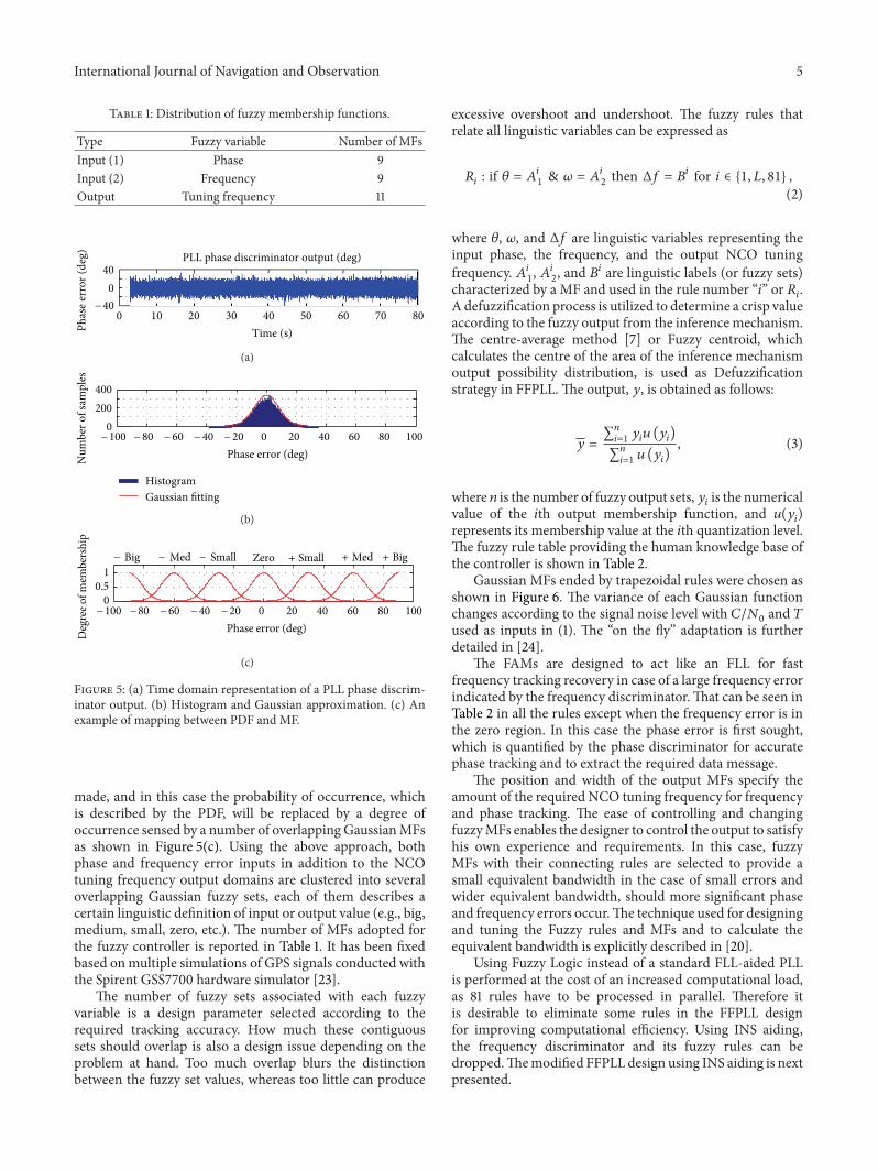
Figure 5 shows the time domain representation of thephase discriminator output during tracking of the incomingsignal received from PRN 5 using a 4Hz third-order PLLwith 1ms coherent integration time and its histogram approx-imated as Gaussian. The corresponding Gaussian ProbabilityDensity Function (PDF) covers the signal expected valuesunder standard tracking conditions at a certain 𝐶/𝑁
0level,
and it can be linguistically described as zero state if comparedto the ideal phase discriminator output. The mean andstandard deviation, which are the two parameters governingthe Gaussian distribution function, are directly related tothe signal dynamics and signal quality, respectively. Receiverdynamics can cause a phase tracking error, and hence thedistribution mean will be shifted from zero. On the otherhand, the changes in the signal quality will result in changesin the standard deviation as illustrated in (1). An appropriatemapping between the signal PDF and fuzzy MFs can be
International Journal of Navigation and Observation 5
Table 1: Distribution of fuzzy membership functions.
Type Fuzzy variable Number of MFsInput (1) Phase 9Input (2) Frequency 9Output Tuning frequency 11
0 10 20 30 40 50 60 70 80
040
Time (s)Phas
e err
or (d
eg) PLL phase discriminator output (deg)
40−
(a)
0 20 40 60 80 1000
200400
Phase error (deg)Num
ber o
f sam
ples
− 20− 40− 60− 80− 100
Gaussian fittingHistogram
(b)
0 20 40 60 80 1000
0.51
Phase error (deg)− 20− 40− 60− 80− 100
Deg
ree o
f mem
bers
hip
− Big Zero + Small + Med + Big− Med − Small
(c)
Figure 5: (a) Time domain representation of a PLL phase discrim-inator output. (b) Histogram and Gaussian approximation. (c) Anexample of mapping between PDF and MF.
made, and in this case the probability of occurrence, whichis described by the PDF, will be replaced by a degree ofoccurrence sensed by a number of overlapping GaussianMFsas shown in Figure 5(c). Using the above approach, bothphase and frequency error inputs in addition to the NCOtuning frequency output domains are clustered into severaloverlapping Gaussian fuzzy sets, each of them describes acertain linguistic definition of input or output value (e.g., big,medium, small, zero, etc.). The number of MFs adopted forthe fuzzy controller is reported in Table 1. It has been fixedbased onmultiple simulations of GPS signals conducted withthe Spirent GSS7700 hardware simulator [23].
The number of fuzzy sets associated with each fuzzyvariable is a design parameter selected according to therequired tracking accuracy. How much these contiguoussets should overlap is also a design issue depending on theproblem at hand. Too much overlap blurs the distinctionbetween the fuzzy set values, whereas too little can produce
excessive overshoot and undershoot. The fuzzy rules thatrelate all linguistic variables can be expressed as
𝑅𝑖
: if 𝜃 = 𝐴𝑖1& 𝜔 = 𝐴𝑖
2then Δ𝑓 = 𝐵𝑖 for 𝑖 ∈ {1, 𝐿, 81} ,
(2)
where 𝜃, 𝜔, and Δ𝑓 are linguistic variables representing theinput phase, the frequency, and the output NCO tuningfrequency. 𝐴𝑖
1, 𝐴𝑖2, and 𝐵𝑖 are linguistic labels (or fuzzy sets)
characterized by a MF and used in the rule number “𝑖” or 𝑅𝑖.
A defuzzification process is utilized to determine a crisp valueaccording to the fuzzy output from the inferencemechanism.The centre-average method [7] or Fuzzy centroid, whichcalculates the centre of the area of the inference mechanismoutput possibility distribution, is used as Defuzzificationstrategy in FFPLL. The output, 𝑦, is obtained as follows:
𝑦 =∑𝑛
𝑖=1𝑦𝑖𝑢 (𝑦𝑖)
∑𝑛
𝑖=1𝑢 (𝑦𝑖)
, (3)
where 𝑛 is the number of fuzzy output sets,𝑦𝑖is the numerical
value of the 𝑖th output membership function, and 𝑢(𝑦𝑖)
represents its membership value at the 𝑖th quantization level.The fuzzy rule table providing the human knowledge base ofthe controller is shown in Table 2.
Gaussian MFs ended by trapezoidal rules were chosen asshown in Figure 6. The variance of each Gaussian functionchanges according to the signal noise level with 𝐶/𝑁
0and 𝑇
used as inputs in (1). The “on the fly” adaptation is furtherdetailed in [24].
The FAMs are designed to act like an FLL for fastfrequency tracking recovery in case of a large frequency errorindicated by the frequency discriminator.That can be seen inTable 2 in all the rules except when the frequency error is inthe zero region. In this case the phase error is first sought,which is quantified by the phase discriminator for accuratephase tracking and to extract the required data message.
The position and width of the output MFs specify theamount of the required NCO tuning frequency for frequencyand phase tracking. The ease of controlling and changingfuzzyMFs enables the designer to control the output to satisfyhis own experience and requirements. In this case, fuzzyMFs with their connecting rules are selected to provide asmall equivalent bandwidth in the case of small errors andwider equivalent bandwidth, should more significant phaseand frequency errors occur.The technique used for designingand tuning the Fuzzy rules and MFs and to calculate theequivalent bandwidth is explicitly described in [20].
Using Fuzzy Logic instead of a standard FLL-aided PLLis performed at the cost of an increased computational load,as 81 rules have to be processed in parallel. Therefore itis desirable to eliminate some rules in the FFPLL designfor improving computational efficiency. Using INS aiding,the frequency discriminator and its fuzzy rules can bedropped.Themodified FFPLL design using INS aiding is nextpresented.

6 International Journal of Navigation and Observation
Table 2: Fuzzy rules.
𝜔𝜃
−B −MB −M −S Ze +S +M +MB +B−B +B +B +B +B +B +B +B +B +B−MB +MB +MB +MB +MB +MB +MB +MB +MB +MB−M +M +M +M +M +M +M +M +M +M−S +SM +SM +SM +SM +SM +SM +SM +SM +SMZe −MB −M −SM −S Ze +S +SM +M +MB+S −SM −SM −SM −SM −SM −SM −SM −SM −SM+M −M −M −M −M −M −M −M −M −M+MB −MB −MB −MB −MB −MB −MB −MB −MB −MB+B −B −B −B −B −B −B −B −B −B±B: ±big; ±MB: ±medium big; ±M: ±medium; ±SM: ±small medium; ±S: ±small; Ze: zero.
Phase error (rad)Deg
ree o
f mem
bers
hip
NB NMB NM NS ZE PS PM PMB PB
− 1.5 − 1 − 0.5 0 0.5 1 1.5
10.5
0
(a)
Frequency error (rad/s)Deg
ree o
f mem
bers
hip
NB NMB NM NS ZE PS PM PMB PB
− 1.5 − 1 − 0.5 0 0.5 1 1.5
10.5
0
(b)
0 1 2 3
NCO tuning frequency (Hz)Deg
ree
of
mem
ber
ship
NB NMB NM NSM NS ZE PS PSM PM PMB PB
− 3 − 2 − 1
1
0.5
0
(c)
Figure 6: Inputs and output membership functions.
3. INS-Assisted FFPLL Design
Coupling GPS and INS signals provides a good solutionfor improving guidance of high-rate maneuvering platforms.The concept links GPS and INS to allow aiding. Aidingcan be performed in several ways. GPS can be used toperiodically update the state vector of the navigation filter forcalibrating the errors inherent to inertial sensors. The INScan improve tracking and reacquisition time by providinga reference signal to the GPS receiver tracking loops. GPSand inertial signals can be coupled using KF techniques tofuse navigation information and handle short GPS outages,signal interferences, or intentional jamming [25]. The levels
of performance achieved depend on the grade of the INS andthe GPS satellites visibility and are driven generally by therequired accuracy or missile-target miss distance. Couplingbecomes necessary onmissile systems and projectiles in orderto mitigate the effects of extreme dynamics, rapidly changingGPS visibility and potential jamming [26, 27].
Based on different data fusion strategies, GPS/INS inte-grated systems can be classified into three types: looselycoupled GPS/INS, tightly coupled GPS/INS, and ultratightGPS/INS integration [28]. As the main objective of theproposed research is to aid the GPS tracking loop withINS data, the coupling filter corresponds to an ultra-tightintegration architecture [29]. This combines the GPS signaltracking functions, the INS data, and the integration filterinto a single estimation algorithm. In this algorithm the INSmeasurements are fed back to the receiver as seen in Figure 2for decreasing GPS signal tracking errors and enhancing thefinal GPS positioning performance.
During GPS outages, the INS-derived Doppler can becontinuously estimated and used for assisting GPS trackingloops by directly pulling the receiver back to tracking modewithout passing through an acquisition step if signal lock islost due to interference or jamming. The INS data of interestto assist the tracking loop is the INS Doppler, which canbe extracted for the proposed GPS/INS integration schemethrough the sequence now explained. Using ephemeris datacalculated with the incoming data bits extracted during thesignal tracking phase, the satellite positions and velocitiesare calculated in the Earth-Centered, Earth-Fixed (ECEF)coordinate frame. This information is then combined withthe calculated ECEF navigation coordinates using INS onlyin a strapdown integration scheme to estimate the associatedDoppler through the steps described below [30].
Firstly, the line of sight (LOS) between the 𝑘th satellite andthe INS processed location is calculated as
e𝑘
=1
𝑟𝑘
(xINS − x𝑠𝑘
) ,
𝑟𝑘
= √(xINS − x𝑠𝑘
)𝑇
(xINS − x𝑠𝑘
) ,
(4)

International Journal of Navigation and Observation 7
where 𝑟𝑘is the distance between the 𝑘th satellite and the INS
coordinates, and e𝑘is the unit vector of the LOS between the
𝑘th satellite and the INS position. xINS represents the INScoordinates in the ECEF, while x
𝑠𝑘represents the 𝑘th satellite
position in ECEF. Secondly, INS Doppler (𝑓𝑑-INS) is derived
from (4) using
𝑓𝑑-INS,𝑘 =
1
𝜆𝐿1
e𝑇𝑘
(vINS − v𝑠𝑘
) , (5)
where vINS and v𝑠𝑘are the INS-derived velocity and the 𝑘th
satellite velocity in the ECEF, respectively. 𝜆𝐿1
is the GPS L1frequency wavelength.
The INS-estimated Doppler is inherently corrected for asmall earth rotation through the strapdown mechanizationprocess. However, other small errors such as satellite andreceiver clock errors and ionospheric errors are neglectedassuming that any errors in frequency aiding to the trackingloop is compensated using the robust process of fuzzy phasetuning.
The use of INS-estimatedDoppler reduces the complexityof the fuzzy tracking loop by using only the phase discrimina-tor output as a single input to the fuzzy processor and the INSDoppler for tuning the frequency. The INS Doppler is addedto the IF frequency (𝑓IF) and is then subtracted from theNCOgenerated carrier frequency (𝑓
𝑐-NCO).The resulting frequencycorresponds to a frequency correction signal (Δ𝑓correction)that is used to adjust the NCO tuning frequency (Δ𝑓).Therefore only 9 fuzzy rules, which correspond to the phasetuning cells in Table 2, instead of the 81 rules in the FFPLLoriginal design, are used for the input fuzzy sets.The completeINS-assisted FFPL is shown in Figure 7.
Before assessing the performance of the FFPLL andthe INS-aided FFPLL with experimental data collections,simulation tests and comparison with Kalman filter tracking(Section 4), it is of interest to perform a qualitative com-parison with other recently published methods. The generaltracking problem always involves some form of Bayesianfiltering. If the conditional probability density functions areknown to be jointly Gaussian and that the observations relatelinearly to the tracked state variables, then the appropriateand optimum Bayesian filter is the standard Kalman filterwhich has been extensively published since the 1960s. If theobservations relate to the state variables in a mildly nonlinearfashion then the conditional densities are only approximatelyGaussian. A practical implementation of a Bayesian filter isthen the family of extended Kalman filters, scented variants,and so forth. If the relation of the observations to the statevariables deviates significantly from being linear, then itis necessary to use numerical integration to perform theBayesian filter iterations. A practical algorithm that has beenrecently adopted for this purpose is the particle filter [31].However, the applicability of these methods is based onthe assumption that the conditional density functions areknown. If the density functions are not explicitly knownthen a practical alternative is to use Fuzzy Logic-basedBayesian filters. Fuzzy Logic membership functions allowthe filter to be designed in a robust albeit suboptimal waythat is based on reasonable statistical modeling assumptions
Table 3: Error characteristics of Litton LN-200 IMU.
Sources 1-𝜎 error UnitsGyro bias 0.35 deg/hrGyro scale factor 100 ppmGyro misalignment 0.1 mradGyro g drift 0.5 deg/hr/gGyro g2 drift 0.05 deg/hr/g2
Gyro random walk 0.05 deg/√hrAccel. bias 0.07 mgAccel. scale factor 300 ppmAccel. misalignment 0.1 mradAccel. random walk 0.03 m/s/√hr
[32]. As demonstrated in this paper, good dynamic trackingperformance is achievable with minimal prior modelinginformation. Statistical modeling is difficult in the context ofcapricious jamming signals which gives impetus to the use offuzzy Logic controllers.
4. Experimental Test Description
The main test to assess the proposed INS-assisted FFPLLwas conducted using real GPS signals, which were processedwith real INS data processing and a GPS jammer. However,because it is very hard to conduct an experimental test thatincludes missile level dynamics and that is still consistentwith the scope of the research, simulated GPS and INSsignals are first used with high dynamics to assess theperformance and the validity of the proposed algorithm formissile applications.
4.1. Simulator Tests. The proposed algorithm was first testedusing the Spirent GSS7700 simulator [23]. The simulatoris capable of providing simulated inertial sensors measure-ments with a controllable output rate that are preciselysynchronized with the GPS RF signals. According to the typeof application adopted in this work, the tactical grade LittonLN-200 inertial measuring unit (IMU) has been simulatedand used. The error characteristics of this IMU are shown inTable 3.
Although it is proposed to perform a complete GPS/INSultra-tight integration, RF signal processing is developed upto the level of signal tracking and solved the navigation databits to obtain the GPS time for synchronization purposes.Simulated IMU measurements are processed to calculate theINS solution through the strapdown mechanization process.To get close to the ultra-tight integration objective, the IMUand GPS simulated data are tightly integrated through anextended Kalman filter (EKF) [30] to provide a correctedestimate of the INS solution.The corresponding INSDoppleris estimated as per (4) and (5) using the GPS data providedby the simulator. As a final step, the calculated INS-derivedDoppler is used separately to aid the RF signal trackingprocess through FFPLL. This approach is clearly illustratedin Figure 8 as amodified version of the ultra-tight integrationscheme introduced in Section 1.

8 International Journal of Navigation and Observation
Phase discriminator
Fuzzification DefuzzificationIncoming signal
FFPLL
NCO
INS + −+
++
+
Fuzzy rules(9 rules)
𝑓𝑑−INS 𝑓𝑐−INS 𝑓𝑐−NCO
Figure 7: INS-assisted FFPLL.
Inertialnavigation algorithm
IMUsimulated
data
Sensorsreadings
EKF
EstimatedDoppler
Sensorserrors
Position
velocity
attitude
GPSsimulated
data
FFPLLINS
Dopplercalculation
GPS satellitespositions and
velocities
GPS RFdata
GPS H/W simulator
Pseudorangesand Doppler
measurements
Figure 8: Process used to calculate INS Doppler to aid FFPLL.
The test procedure and process algorithm (see Figure 8)are conducted through a large number of scenarios that showconsistent results. One of these scenarios is presented herein.
The scenario considered here comprises the effect ofmissile manoeuvres near an interference source. During themanoeuvre, the GPS signal 𝐶/𝑁
0changes with the distance
from the interference source. The missile velocity in thisscenario is increased to reach 300m/s, performing hardmanoeuvres with acceleration up to 8 g and jerks up to 50 g/s.The dynamic profile of this scenario is illustrated in Figure 9,while Figure 10 shows the 3D plot of the missile’s trajectoryand its manoeuvres near the jammer.
A CW jammer producing 45 dB (J/S) of jamming signalis simulated in this scenario. Estimated 𝐶/𝑁
0changes as
the missile performs an evasive manoeuvre to escape thisjamming are shown in Figure 11. As shown in [20], the
FFPLL is capable of maintaining signal lock regardless of themissile dynamics or if low or moderate interference levelsare applied. Very accurate Doppler estimates, extracted fromtactical grade IMU measurements, are helping to providecontinuous signal tracking even if a high level of interfer-ence is applied. When tracking is switched from FFPLLto INS-assisted FFPLL, course frequency tracking is totallydependent on INS-provided Doppler, and hence the fuzzyprocessor is responsible only for tracking frequency errorsby fine tuning and for providing phase tracking. Using a oneinput fuzzy processor reduces drastically its complexity andthe number of fuzzy rules processed in parallel. Consequentlythe computational load gets reduced as will be described later.
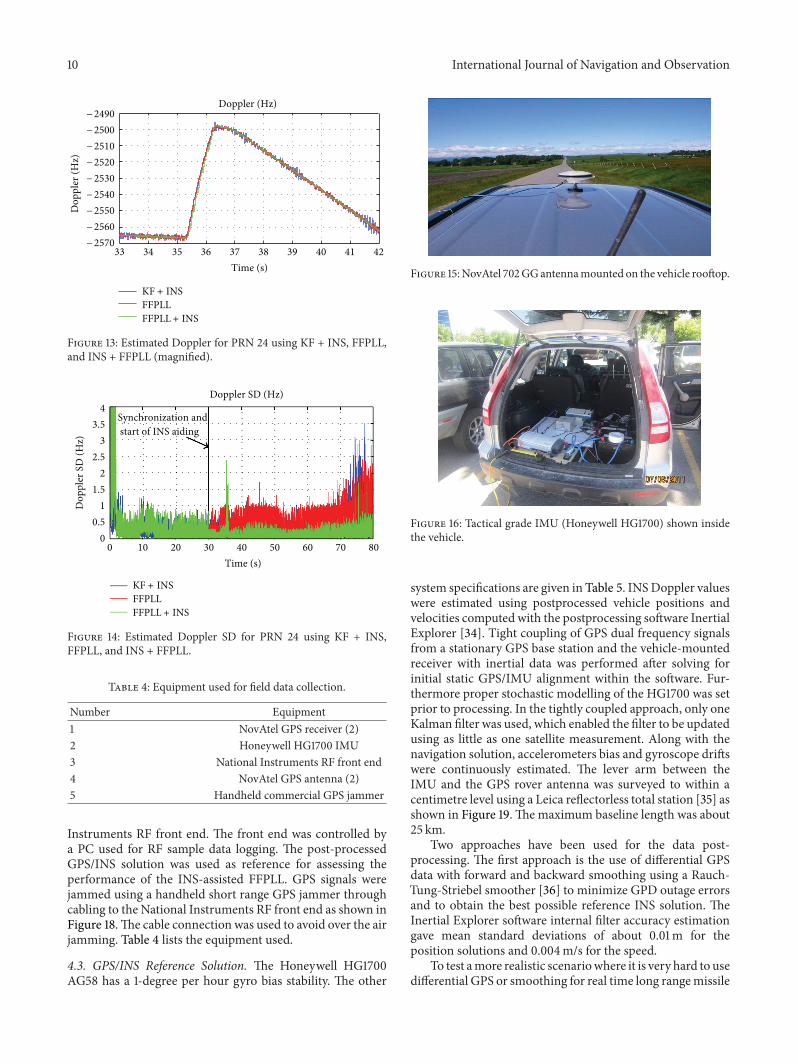
Figures 12 and 13 show the estimated Doppler for PRN24 for the duration of the entire scenario and a magnifiedversion for better illustration, respectively. The Doppler is

International Journal of Navigation and Observation 9
0 10 20 30 40 50 60 70 80 90 1000
200400
Time (s)
Vel
. (m
/s) Receiver dynamics
(a)
0 10 20 30 40 50 60 70 80 90 100048
Time (s)
Acc
. (g)
(b)
0 10 20 30 40 50 60 70 80 90 1000
40
Time (s)
Jerk
(g/s
)
(c)
Figure 9: Receiver dynamics profile.
50.9650.98
5151.02
1200
1400
1600
1800
2000
2200
Longitude (deg)
Hei
ght (
m)
Latitude (deg)
− 114 − 113.9 − 113.8 − 113.7 − 113.6 − 113.5
Figure 10: 3D plot of the missile manoeuvres near an interferencesource.
estimated during signal tracking using KF + INS, FFPLL,and FFPLL + INS. Figure 14 shows the estimated Dopplerstandard deviation using these three algorithms. At epoch30, GPS time is extracted under proper signal trackingusing the original FFPLL, and synchronization is performedwith INS aiding data to switch from the original FFPLL toFFPLL + INS. The Kalman filter used here is based on themodel described in [26–28] and uses discriminator outputsas measurement updates. It is also modified to accept INSDoppler aiding for a fair comparison with the INS-assistedFFPLL. The INS-assisted Kalman filter is labeled KF + INS.
From the previous results, it can be seen that the INS-assisted FFPLL algorithm has successfully passed the validitytest by providing continuous tracking during combinedincidence of very high dynamics and variable jamming levels.As shown in Figure 13 for PRN24, thanks to accurateDopplerestimates from the simulated Litton IMU, the estimatedDoppler is more accurate than the one estimated withthe standalone FFPLL. A more complete assessment of the
0 10 20 30 40 50 60 70 80242628303234363840
Time (s)
Figure 11: 𝐶/𝑁0estimated for PRN 24 during missile manoeuvres.
0 20 40 60 80Time (s)
Dop
pler
(Hz)
Doppler (Hz)− 2400
− 2500
− 2600
− 2700
− 2800
− 2900
− 3000
− 3100
KF + INSFFPLLFFPLL + INS
Figure 12: Estimated Doppler for PRN 24 using KF + INS, FFPLL,and INS + FFPLL.
proposed algorithm is given in the next section where realGPS and IMU signals have been collected and analyzed.
4.2. Experimental Test Description. In order to test the pro-posed signal tracking architecture using real GPS and INSdata, experimental tests have been conducted in a vehicle.Photos of the testing equipment are shown in Figures 15 and16. They comprise a GPS antenna and the NovAtel SPANHoneywell HG1700 system. The lever arm was measuredduring the experiment. To remain as close as possible tothe scope of the research, dynamics conditions limited bythe vehicle capability have been reproduced during the datacollection. Logging and control systems were loaded in thevehicle. The complete test setup is illustrated in Figure 17.
Rover data was collected with a single antenna using twoseparate setups. The NovAtel 702GG antenna was used tocollectGPS signals, and its outputwas split between anOEM4dual frequency GPS receiver, which was connected to atactical grade IMU (Honeywell HG1700 [33]), and a National
10 International Journal of Navigation and Observation
33 34 35 36 37 38 39 40 41 42Time (s)
Dop
pler
(Hz)
Doppler (Hz)− 2490− 2500− 2510− 2520− 2530− 2540
− 2560− 2570
KF + INSFFPLLFFPLL + INS
− 2550
Figure 13: Estimated Doppler for PRN 24 using KF + INS, FFPLL,and INS + FFPLL (magnified).
0 10 20 30 40 50 60 70 800
0.51
1.52
2.53
3.54
Time (s)
Dop
pler
SD
(Hz)
Doppler SD (Hz)
KF + INSFFPLLFFPLL + INS
Synchronization andstart of INS aiding
Figure 14: Estimated Doppler SD for PRN 24 using KF + INS,FFPLL, and INS + FFPLL.
Table 4: Equipment used for field data collection.
Number Equipment1 NovAtel GPS receiver (2)
2 Honeywell HG1700 IMU3 National Instruments RF front end4 NovAtel GPS antenna (2)
5 Handheld commercial GPS jammer
Instruments RF front end. The front end was controlled bya PC used for RF sample data logging. The post-processedGPS/INS solution was used as reference for assessing theperformance of the INS-assisted FFPLL. GPS signals werejammed using a handheld short range GPS jammer throughcabling to the National Instruments RF front end as shown inFigure 18.The cable connection was used to avoid over the airjamming. Table 4 lists the equipment used.
4.3. GPS/INS Reference Solution. The Honeywell HG1700AG58 has a 1-degree per hour gyro bias stability. The other
Figure 15:NovAtel 702GGantennamounted on the vehicle rooftop.
Figure 16: Tactical grade IMU (Honeywell HG1700) shown insidethe vehicle.
system specifications are given in Table 5. INSDoppler valueswere estimated using postprocessed vehicle positions andvelocities computed with the postprocessing software InertialExplorer [34]. Tight coupling of GPS dual frequency signalsfrom a stationary GPS base station and the vehicle-mountedreceiver with inertial data was performed after solving forinitial static GPS/IMU alignment within the software. Fur-thermore proper stochastic modelling of the HG1700 was setprior to processing. In the tightly coupled approach, only oneKalman filter was used, which enabled the filter to be updatedusing as little as one satellite measurement. Along with thenavigation solution, accelerometers bias and gyroscope driftswere continuously estimated. The lever arm between theIMU and the GPS rover antenna was surveyed to within acentimetre level using a Leica reflectorless total station [35] asshown in Figure 19.Themaximum baseline length was about25 km.
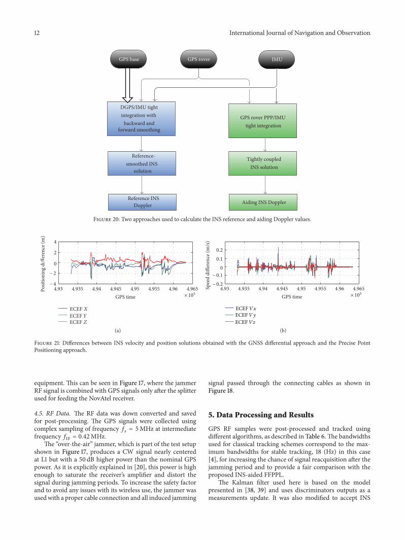
Two approaches have been used for the data post-processing. The first approach is the use of differential GPSdata with forward and backward smoothing using a Rauch-Tung-Striebel smoother [36] to minimize GPD outage errorsand to obtain the best possible reference INS solution. TheInertial Explorer software internal filter accuracy estimationgave mean standard deviations of about 0.01m for theposition solutions and 0.004m/s for the speed.
To test amore realistic scenariowhere it is very hard to usedifferential GPS or smoothing for real time long rangemissile

International Journal of Navigation and Observation 11
NovAtel GPS antennaNovAtel GPS antenna
NovAtel GPS receiverSplitter
NovAtel GPS receiver
GPS L1Combiner jammer
Reference data logging
RoverBase
NI RF front end
IMU HGI700
Figure 17: Test setup.
Figure 18: Handheld jammer signal combined with GPS signal viacabling and connected to the logging system.
Table 5: HG1700 IMU system specifications.
Description UnitsOutput data rate 100/600 HzGyro input range ±1,000 deg/secGyro rate scale factor 150 ppmGyro bias (one sigma) 1 deg/hrGyro angular random walk 0.125 deg/√hrAccel. range ±50 gAccel. linearity 500 ppmAccel. scale factor 300 ppmAccel. bias 1.0 mg
applications, the INS solutionwas recalculated using a secondapproach where only the vehicle-mounted GPS data wasused in a forward solution with a Precise Point Positioning(PPP) method [37]. The Inertial Explorer software internalfilter for this approach gave a mean standard deviation of
Figure 19: Lever arm surveying using Leica TCR705 reflectorlesstotal station.
0.17m, a maximum of 1.16m for the position solutions, and0.01m/s with a maximum of 0.09m/s for the speed. Thesetwo approaches are described in Figure 20 in term of thedifferences in INS solution estimates for the positions, whilethe position and velocity results are shown in Figure 21.
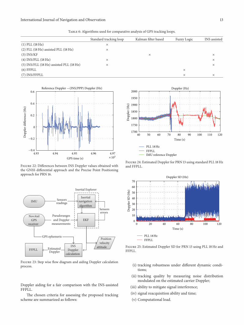
As a following step, the INS Doppler was calculated asdescribed earlier and used as an aiding signal for the FFPLL,which is processed separately. An example of INS Dopplerdifferences between the two approaches for PRN 16 is shownin Figure 22.The experiment is also described in the stepwiseflow diagram shown in Figure 23.
4.4. INS Doppler. In order to insure that only INS-derivedDoppler were extracted from the tightly coupled solutionduring jamming periods, artificial outages were simulated inpost-processing during the periods of jamming. Indeed thewired GPS jammer perturbed only the RF samples collectedby the NI front end and not the GPS receiver used for the INS
12 International Journal of Navigation and Observation
GPS base GPS rover IMU
DGPS/IMU tightintegration with
backward andGPS rover PPP/IMU
tight integration
Reference-smoothed INS
solution
Tightly coupled INS solution
Reference INSDoppler Aiding INS Doppler
forward smoothing
Figure 20: Two approaches used to calculate the INS reference and aiding Doppler values.
4.93 4.935 4.94 4.945 4.95 4.955 4.96 4.965GPS time × 105
4
2
0
− 2
− 4
Posit
ioni
ng d
iffer
ence
(m)
(a)
Spee
d di
ffere
nce (
m/s
)
0.20.1
0− 0.1− 0.2
4.93 4.935 4.94 4.945 4.95 4.955 4.96 4.965GPS time × 105
(b)
Figure 21: Differences between INS velocity and position solutions obtained with the GNSS differential approach and the Precise PointPositioning approach.
equipment. This can be seen in Figure 17, where the jammerRF signal is combined with GPS signals only after the splitterused for feeding the NovAtel receiver.
4.5. RF Data. The RF data was down converted and savedfor post-processing. The GPS signals were collected usingcomplex sampling of frequency 𝑓
𝑠= 5MHz at intermediate
frequency 𝑓IF = 0.42MHz.The “over-the-air” jammer, which is part of the test setup
shown in Figure 17, produces a CW signal nearly centeredat L1 but with a 50 dB higher power than the nominal GPSpower. As it is explicitly explained in [20], this power is highenough to saturate the receiver’s amplifier and distort thesignal during jamming periods. To increase the safety factorand to avoid any issues with its wireless use, the jammer wasusedwith a proper cable connection and all induced jamming
signal passed through the connecting cables as shown inFigure 18.
5. Data Processing and Results
GPS RF samples were post-processed and tracked usingdifferent algorithms, as described in Table 6.The bandwidthsused for classical tracking schemes correspond to the max-imum bandwidths for stable tracking, 18 (Hz) in this case[4], for increasing the chance of signal reacquisition after thejamming period and to provide a fair comparison with theproposed INS-aided FFPPL.
The Kalman filter used here is based on the modelpresented in [38, 39] and uses discriminators outputs as ameasurements update. It was also modified to accept INS
International Journal of Navigation and Observation 13
Table 6: Algorithms used for comparative analysis of GPS tracking loops.
Standard tracking loop Kalman filter based Fuzzy Logic INS assisted(1) PLL (18Hz) ×
(2) FLL (18Hz) assisted PLL (18Hz) ×
(3) INS/KF × ×
(4) INS/PLL (18Hz) × ×
(5) INS/FLL (18Hz) assisted PLL (18Hz) × ×
(6) FFPLL ×
(7) INS/FFPLL × ×
× 1054.93 4.94 4.95 4.96 4.97
0
0.2
0.4
0.6
GPS time (s)
Do
pp
ler
dif
fere
nce
(H
z)
− 0.2
− 0.4
Reference Doppler —(INS/PPP) Doppler (Hz)
Figure 22: Differences between INS Doppler values obtained withthe GNSS differential approach and the Precise Point Positioningapproach for PRN 16.
Inertialnavigation algorithm
IMU Sensorsreadings
EKF
EstimatedDoppler
Sensorserrors
Positionvelocity
attitude
NovAtelGPS
receiver
FFPLLINS
Dopplercalculation
GPS ephemeris
Inertial Explorer
Pseudorangesand Doppler
measurements
Figure 23: Step wise flow diagram and aiding Doppler calculationprocess.
Doppler aiding for a fair comparison with the INS-assistedFFPLL.
The chosen criteria for assessing the proposed trackingscheme are summarized as follows:
40 50 60 70 80 90 100 110 1201700
1750
1800
1850
1900
1950
2000
Time (s)
Dop
pler
(Hz)
Doppler (Hz)
PLL 18 HzFFPLLIMU reference Doppler
Figure 24: Estimated Doppler for PRN 13 using standard PLL 18Hzand FFPLL.
0 20 40 60 80 100 1200
10
20
30
40
50
60
70
Time (s)
Dop
pler
SD
(Hz)
Doppler SD (Hz)
PLL 18 HzFFPLL
Figure 25: Estimated Doppler SD for PRN 13 using PLL 18Hz andFFPLL.
(i) tracking robustness under different dynamic condi-tions;
(ii) tracking quality by measuring noise distributionmodulated on the estimated carrier Doppler;
(iii) ability to mitigate signal interference;(iv) signal reacquisition ability and time;(v) Computational load.

14 International Journal of Navigation and Observation
40 45 50 55 60 65 70 75 80 85 90450
500
550
600
650
Time (s)
Do
pp
ler
(Hz)
Doppler (Hz)
KF + INS
FFPLLFFPLL + INS
Figure 26: Estimated Doppler for PRN 16 using KF + INS, FFPLL,and INS + FFPLL.
40 45 50 55 60 65 70 75 80 85 9016001650170017501800185019001950200020502100
Time (s)
Dop
pler
(Hz)
Doppler (Hz)
KF + INSFFPLLFFPLL + INS
Figure 27: Estimated Doppler for PRN 13 using KF + INS, FFPLL,and FPLL + INS.
All the above points of assessment, except the computa-tional load, can be investigated by analyzing the estimatedDoppler during signal tracking, taking into considerationthat, when the system is in tracking mode, it tracks the signalphase as well. During processing, this estimated Doppler isfirst compared to the INS reference Doppler, calculated using(5), to ensure that the solution is correct and not biased.
An analysis of the tracking results for two specific GPSsignals, PRN code 16 and 13, which were tracked at elevationsof about 30 degrees and 60 degrees, respectively, usingstandard and nonstandard tracking algorithms, is conducted.The associated results are assessed in a concise manner, asall tracking results for the other available GPS signals showconsistent results and lead to the same conclusion.
After processing RF data using the approaches listed inTable 6, it was found that none of them were able to trackthe GPS signal phase during jamming periods. Moreoverit was observed that the standard tracking schemes, evenwith INS aiding, were not able to reacquire the signal and
0102030405060708090
100
Used algorithm
Proc
essin
g tim
e rat
io (%
)
FFPLL FFPLL + INS
Figure 28: Average fuzzy processing time ratio for standalone andassisted FFPLL.
2 4 6 8 10 12 14 16 18 200
0.2
0.4
0.6
0.8
1
1.2
1.4
1.6
1.8
2
Ave
rage
pro
cess
ing
time (
s)
Original fuzzy processorReduced fuzzy processor
Number of samples × 103
Figure 29: Processing time of the original and the reduced fuzzyprocessors.
82 82.5 83 83.5 84 84.5 85
540
550
560
570
580
590
Time (s)
Dop
pler
(Hz)
Doppler (Hz)
KF + INSFFPLLFFPLL + INS
Figure 30: Estimated Doppler for PRN 16 using KF + INS, FFPLL,and INS/FFPLL magnified for transient time illustration.
International Journal of Navigation and Observation 15
81 81.5 82 82.5 83 83.5 84 84.5 851770
1780
1790
1800
1810
1820
1830
1840
Time (s)
Dop
pler
(Hz)
Doppler (Hz)
KF + INSFFPLLFFPLL + INS
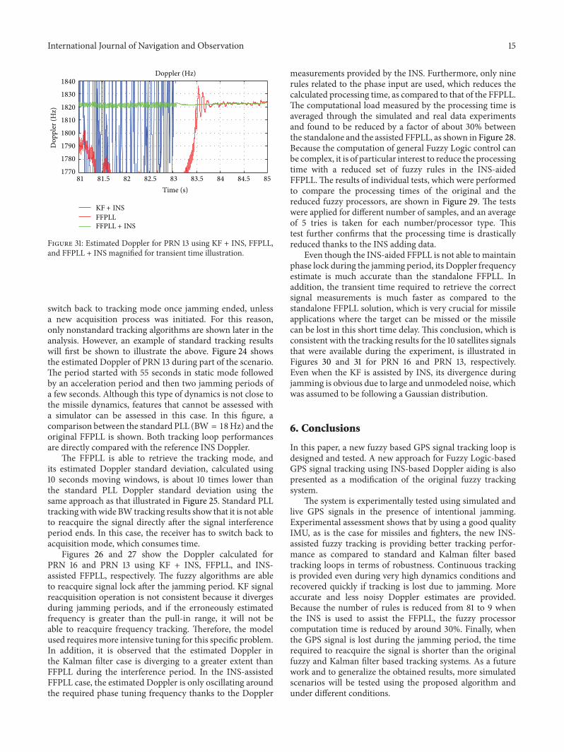
Figure 31: Estimated Doppler for PRN 13 using KF + INS, FFPLL,and FFPLL + INS magnified for transient time illustration.
switch back to tracking mode once jamming ended, unlessa new acquisition process was initiated. For this reason,only nonstandard tracking algorithms are shown later in theanalysis. However, an example of standard tracking resultswill first be shown to illustrate the above. Figure 24 showsthe estimated Doppler of PRN 13 during part of the scenario.The period started with 55 seconds in static mode followedby an acceleration period and then two jamming periods ofa few seconds. Although this type of dynamics is not close tothe missile dynamics, features that cannot be assessed witha simulator can be assessed in this case. In this figure, acomparison between the standard PLL (BW = 18Hz) and theoriginal FFPLL is shown. Both tracking loop performancesare directly compared with the reference INS Doppler.
The FFPLL is able to retrieve the tracking mode, andits estimated Doppler standard deviation, calculated using10 seconds moving windows, is about 10 times lower thanthe standard PLL Doppler standard deviation using thesame approach as that illustrated in Figure 25. Standard PLLtrackingwithwide BW tracking results show that it is not ableto reacquire the signal directly after the signal interferenceperiod ends. In this case, the receiver has to switch back toacquisition mode, which consumes time.
Figures 26 and 27 show the Doppler calculated forPRN 16 and PRN 13 using KF + INS, FFPLL, and INS-assisted FFPLL, respectively. The fuzzy algorithms are ableto reacquire signal lock after the jamming period. KF signalreacquisition operation is not consistent because it divergesduring jamming periods, and if the erroneously estimatedfrequency is greater than the pull-in range, it will not beable to reacquire frequency tracking. Therefore, the modelused requires more intensive tuning for this specific problem.In addition, it is observed that the estimated Doppler inthe Kalman filter case is diverging to a greater extent thanFFPLL during the interference period. In the INS-assistedFFPLL case, the estimated Doppler is only oscillating aroundthe required phase tuning frequency thanks to the Doppler
measurements provided by the INS. Furthermore, only ninerules related to the phase input are used, which reduces thecalculated processing time, as compared to that of the FFPLL.The computational load measured by the processing time isaveraged through the simulated and real data experimentsand found to be reduced by a factor of about 30% betweenthe standalone and the assisted FFPLL, as shown in Figure 28.Because the computation of general Fuzzy Logic control canbe complex, it is of particular interest to reduce the processingtime with a reduced set of fuzzy rules in the INS-aidedFFPLL.The results of individual tests, which were performedto compare the processing times of the original and thereduced fuzzy processors, are shown in Figure 29. The testswere applied for different number of samples, and an averageof 5 tries is taken for each number/processor type. Thistest further confirms that the processing time is drasticallyreduced thanks to the INS adding data.
Even though the INS-aided FFPLL is not able to maintainphase lock during the jamming period, its Doppler frequencyestimate is much accurate than the standalone FFPLL. Inaddition, the transient time required to retrieve the correctsignal measurements is much faster as compared to thestandalone FFPLL solution, which is very crucial for missileapplications where the target can be missed or the missilecan be lost in this short time delay. This conclusion, which isconsistent with the tracking results for the 10 satellites signalsthat were available during the experiment, is illustrated inFigures 30 and 31 for PRN 16 and PRN 13, respectively.Even when the KF is assisted by INS, its divergence duringjamming is obvious due to large and unmodeled noise, whichwas assumed to be following a Gaussian distribution.
6. Conclusions
In this paper, a new fuzzy based GPS signal tracking loop isdesigned and tested. A new approach for Fuzzy Logic-basedGPS signal tracking using INS-based Doppler aiding is alsopresented as a modification of the original fuzzy trackingsystem.
The system is experimentally tested using simulated andlive GPS signals in the presence of intentional jamming.Experimental assessment shows that by using a good qualityIMU, as is the case for missiles and fighters, the new INS-assisted fuzzy tracking is providing better tracking perfor-mance as compared to standard and Kalman filter basedtracking loops in terms of robustness. Continuous trackingis provided even during very high dynamics conditions andrecovered quickly if tracking is lost due to jamming. Moreaccurate and less noisy Doppler estimates are provided.Because the number of rules is reduced from 81 to 9 whenthe INS is used to assist the FFPLL, the fuzzy processorcomputation time is reduced by around 30%. Finally, whenthe GPS signal is lost during the jamming period, the timerequired to reacquire the signal is shorter than the originalfuzzy and Kalman filter based tracking systems. As a futurework and to generalize the obtained results, more simulatedscenarios will be tested using the proposed algorithm andunder different conditions.
16 International Journal of Navigation and Observation
References
[1] K. Borre, D. M. Akos, N. Bertelsen, P. Rinder, and S. H.Jensen,ASoftware-DefinedGPS andGALILEOReceiver, a SingleFrequency Approach, Birkhauser, Boston, Mass, USA, 2007.
[2] P. Ward, “Performance comparisons between FLL, PLL anda novel FLL-assisted-PLL carrier tracking loop under RFinterference conditions,” in Proceedings of the 11th InternationalTechnical Meeting of the Satellite Division of the Institute ofNavigation, pp. 783–795, Nashville, Tenn, USA, 1998.
[3] R. E. Best, Phase-Locked Loops: Design, Simulation, and Appli-cations, McGraw-Hill, New York, NY, USA, 4th edition, 1999.
[4] E. D. Kaplan and C. J. Hegarty, Understanding GPS: Principlesand Applications, Artech House, Norwood, Mass, USA, 2ndedition, 2006.
[5] C. O’Driscoll, D. Borio, M. Petovello, T. Williams, and G.Lachapelle, “The soft approach: a recipe for a multi-system,multi-frequency GNSS receiver,” InsideGNSS, vol. 4, pp. 46–51,2009.
[6] R. G. Brown and P. Y. C. Hwang, Introduction to RandomSignals and Applied Kalman Filtering with Matlab Exercises andSolutions, JohnWiley & Sons, New York, NY, USA, 3rd edition,1997.
[7] T. J. Ross, J. M. Booker, and W. J. Parkinson, Fuzzy Logicand Probability Applications, American Statistical AssociationSociety for Industrial and Applied Mathematics, Alexandria,Va, USA, 2002.
[8] A. M. Kamel, “Design and testing of an intelligent GPS trackingloop for noise reduction and high dynamics applications,” inProceedings of the 23rd International Technical Meeting of theSatellite Division of the Institute of Navigation (ION GNSS’10),pp. 3235–3243, Portland, Ore, USA, September 2010.
[9] A. M. Kamel, D. Borio, J. Nielsen, and G. Lachapelle, “Mit-igation for missiles (fuzzy logic and intelligent trackingloops cope with interference),” GPS World, 2011, http://www.gpsworld.com/defense/precision-guidance/mitigation-missil-es-11710.
[10] R. E. Phillips and G. T. Schmidt, “GPS/INS integration,” Neuillysur Seine, France, 1996.
[11] D. Simon and H. El-Sherief, “Fuzzy phase-locked loops,” inProceedings of the IEEE Position Location and Navigation Sym-posium, pp. 252–259, Las Vegas, Nev, USA, April 1994.
[12] A. Hiliuta, R. Landry, and F. Gagnon, “Fuzzy corrections ina GPS/INS hybrid navigation system,” IEEE Transactions onAerospace and Electronic Systems, vol. 40, no. 2, pp. 591–600,2004.
[13] S. Alban, D. Akos, and S. M. Rock, “Performance analysis andarchitectures for INS-aided GPS tracking loops,” in Proceedingsof ION National Technical Meeting of the Institute of Navigation(NTM), Fairfax, Va, USA, 2003.
[14] J. D. Gautier and B. W. Parkinson, “Using the GPS/INS gener-alized evaluation tool (GIGET) for the comparison of looselycoupled, tightly coupled and ultra-tightly coupled integratednavigation systems,” in Proceedings of ION 59th Annual Meet-ing/CIGTF 22nd Guidance Test Symposium, Albuquerque, NM,USA, 2003.
[15] M. G. Petovello and G. Lachapelle, “Comparison of vector-based software receiver implementations with application toultra-tight GPS/INS integration,” in Proceedings of the 19thInternational Technical Meeting of the Satellite Division of theInstitute of Navigation (ION GNSS’06), pp. 1790–1799, FortWorth Tex, USA, September 2006.
[16] R. Babu, J. Wang, and G. Rao, “Analysis of ultra-tight GPS/INSintegrated system for navigation performance,” inProceedings ofthe International Conference on Signal Processing Communica-tions and Networking (ICSCN’08), pp. 234–237, Chennai, India,January 2008.
[17] M. G. Petovello, C. O. ’Driscoll, and G. Lachapelle, “Ultra-tightGPS/INS for carrier phase positioning in weak signal environ-ments,” in Proceedings of the NATORTO SET-104 Symposium onMilitary Capabilities Enabled by Advances in Navigation Sensors,Antalya, Turkey, 2007.
[18] G. Chen and T. T. Pham, Fuzzy Sets, Fuzzy Logic, and FuzzyControl Systems, CRC Press, New York, NY, USA, 2001.
[19] B. Kosko, Neural Networks and Fuzzy Systems: A DynamicalSystems Approach to Machine Intelligence, Prentice Hall, Engle-wood Cliffs, NJ, USA, 1992.
[20] A. M. M. Kamel, Context aware high dynamics GNSS-INS forinterference mitigation [Ph.D. thesis], Geomatics Engineering,University of Calgary, Calgary, Canada, 2011.
[21] A. J. V. Dierendonck, “GPS receivers,” in Global PositioningSystem: Theory and Applications, B. W. Parkinson, Ed., vol. 1,AIAA, Los Altos, Calif, USA, 1996.
[22] P. Crosta and T. Alenia, “A novel approach to the performanceevaluation of an arctangent discriminator for phase lockedloop and application to the carrier tracking of the ionosphericscintillation,” in Proceedings of the ENC-GNSS 2009, Naples,Italy, 2009.
[23] Spirent, Signal Generator Hardware User Manual, Spirent Com-munications, 2006.
[24] A. M. Kamel, D. Borio, J. Nielsen, and G. Lachapelle, “Inter-ference mitigation for highly dynamic GPS receivers usingintelligent tracking loops,” in Proceedings of the InternationalTechnical Meeting of the Institute of Navigation (ION ITM’11),pp. 374–383, San Diego, Calif, USA, January 2011.
[25] J. Farrell, Aided Navigation: GPS with High Rate Sensors, vol. 1,McGraw-Hill, New York, NY, USA, 1st edition, 2008.
[26] G. M. Siouris, Missile Guidance and Control Systems, Springer,New York, NY, USA, 2004.
[27] J. Wendel and G. F. Trommer, “Tightly coupled GPS/INSintegration for missile applications,” Aerospace Science andTechnology, vol. 8, no. 7, pp. 627–634, 2004.
[28] P. D. Groves, Principles of GNSS, Inertial, and MultisensorIntegrated Navigation Systems, Artech House, Norwood, Mass,USA, 2008.
[29] D. E. Lewis, “Ultra-tightly coupled GPS/INS tracking perfor-mance,” in Proceedings of the AIAA’s 3rd Annual Aviation Tech-nology, Integration, and Operations (ATIO’03), Tech Denver,Colo, USA, 2003.
[30] N. Elsheimy, ENGO 623 Lecture Notes: Inertial Techniques andINS/DGPS Integration, Department of Geomatics Engineering,University of Calgary, Calgary, Canada, 2007.
[31] W. Pedrycz and F. Gomide, An Introduction to Fuzzy Sets:Analysis and Design, MIT Press, Cambridge, Mass, USA, 1998.
[32] P. Closas, C. Fernandez-Prades, J. Diez, and D. de Castro,“Nonlinear Bayesian tracking loops for multipath mitigation,”International Journal of Navigation and Observation, vol. 2012,article 15, 2012.
[33] Honeywell, HG1700 Inertial measurement unit, 2006, http://www.honeywell.com/sites/servlet/com.merx.npoint.servlets.DocumentServlet?docid=D7B652202-0601-F56B-1B7F-829F1A7109E4.

International Journal of Navigation and Observation 17
[34] NovAtel, Inertial explorer data sheet, 2011, http://www.no-vatel.com/assets/Documents/Waypoint/InertialExplorer.pdf.
[35] GlobalSources, “Leica TCR705 reflectorless [TCR705] productdetails,” 2011.
[36] A. H. Jazwinski, Stochastic Processes and Filtering Theory, vol.64, Academic Press, New York, NY, USA, 1970.
[37] J. Kouba and P. Heroux, “Precise point positioning using IGSorbit and clock products,” GPS Solutions, vol. 5, pp. 12–28, 2001.
[38] M. L. Psiaki, “Smoother-basedGPS signal tracking in a softwarereceiver,” in Proceedings of the ION GPS 2001, Salt Lake City,Utah, USA, 2001.
[39] M. L. Psiaki, T. E. Humphreys, A. P. Cerruti, S. P. Powell, andP. M. Kintner, “Tracking L1 C/A and L2C signals through iono-spheric scintillations,” in Proceedings of the 20th InternationalTechnical Meeting of the Satellite Division of the Institute ofNavigation (IONGNSS’07), pp. 246–268, FortWorth, Tex, USA,September 2007.

International Journal of
AerospaceEngineeringHindawi Publishing Corporationhttp://www.hindawi.com Volume 2014
RoboticsJournal of
Hindawi Publishing Corporationhttp://www.hindawi.com Volume 2014
Hindawi Publishing Corporationhttp://www.hindawi.com Volume 2014
Active and Passive Electronic Components
Control Scienceand Engineering
Journal of
Hindawi Publishing Corporationhttp://www.hindawi.com Volume 2014
International Journal of
RotatingMachinery
Hindawi Publishing Corporationhttp://www.hindawi.com Volume 2014
Hindawi Publishing Corporation http://www.hindawi.com
Journal ofEngineeringVolume 2014
Submit your manuscripts athttp://www.hindawi.com
VLSI Design
Hindawi Publishing Corporationhttp://www.hindawi.com Volume 2014
Hindawi Publishing Corporationhttp://www.hindawi.com Volume 2014
Shock and Vibration
Hindawi Publishing Corporationhttp://www.hindawi.com Volume 2014
Civil EngineeringAdvances in
Acoustics and VibrationAdvances in
Hindawi Publishing Corporationhttp://www.hindawi.com Volume 2014
Hindawi Publishing Corporationhttp://www.hindawi.com Volume 2014
Electrical and Computer Engineering
Journal of
Advances inOptoElectronics
Hindawi Publishing Corporation http://www.hindawi.com
Volume 2014
The Scientific World JournalHindawi Publishing Corporation http://www.hindawi.com Volume 2014
SensorsJournal of
Hindawi Publishing Corporationhttp://www.hindawi.com Volume 2014
Modelling & Simulation in EngineeringHindawi Publishing Corporation http://www.hindawi.com Volume 2014
Hindawi Publishing Corporationhttp://www.hindawi.com Volume 2014
Chemical EngineeringInternational Journal of Antennas and
Propagation
International Journal of
Hindawi Publishing Corporationhttp://www.hindawi.com Volume 2014
Hindawi Publishing Corporationhttp://www.hindawi.com Volume 2014
Navigation and Observation
International Journal of
Hindawi Publishing Corporationhttp://www.hindawi.com Volume 2014
DistributedSensor Networks
International Journal of
Related Documents