Research Article Cuspal Displacement Induced by Bulk Fill Resin Composite Polymerization: Biomechanical Evaluation Using Fiber Bragg Grating Sensors Alexandra Vinagre, 1 João Ramos, 1 Sofia Alves, 1 Ana Messias, 1 Nélia Alberto, 2 and Rogério Nogueira 2 1 Faculty of Medicine, University of Coimbra, Avenida Bissaya Barreto, Blocos de Celas, 3000-075 Coimbra, Portugal 2 Instituto de Telecomunicac ¸˜ oes (IT), Campus Universit´ ario de Santiago, 3810-193 Aveiro, Portugal Correspondence should be addressed to Alexandra Vinagre; [email protected] Received 26 November 2015; Revised 18 March 2016; Accepted 21 March 2016 Academic Editor: Feng-Huei Lin Copyright © 2016 Alexandra Vinagre et al. is is an open access article distributed under the Creative Commons Attribution License, which permits unrestricted use, distribution, and reproduction in any medium, provided the original work is properly cited. Polymerization shrinkage is a major concern to the clinical success of direct composite resin restorations. e aim of this study was to compare the effect of polymerization shrinkage strain of two resin composites on cuspal movement based on the use of fiber Bragg grating (FBG) sensors. Twenty standardized Class II cavities prepared in upper third molars were allocated into two groups ( = 10). Restorations involved the bulk fill placement of conventional microhybrid resin composite (Esthet∙X HD, Dentsply DeTrey) (Group 1) or flowable “low-shrinkage” resin composite (SDR, Dentsply DeTrey) (Group 2). Two FBG sensors were used per restoration for real-time measurement of cuspal linear deformation and temperature variation. Group comparisons were determined using ANCOVA ( = 0.05) considering temperature as the covariate. A statistically significant correlation between cuspal deflection, time, and material was observed ( < 0.01). Cuspal deflection reached 8.8 m (0.23%) and 7.8 m (0.20%) in Groups 1 and 2, respectively. When used with bulk fill technique, flowable resin composite SDR induced significantly less cuspal deflection than the conventional resin composite Esthet∙X HD ( = 0.015) and presented a smoother curve slope during the polymerization. FBG sensors appear to be a valid tool for accurate real-time monitoring of cuspal deformation. 1. Introduction Volumetric shrinkage remains a major drawback to the clinical performance of the resin composite restorations. Shrinkage leads to deformation of the resin composites and generates stress due to the confinement of the resin to the cavity walls generated by the bonding procedure. is shrinkage stress is transferred to the tooth and may lead to cuspal deflection or enamel microcracks, whereas stress at the tooth-composite interface increases the likelihood of interfacial adhesive failures [1]. Cuspal deflection occurs due to the interaction between the polymerization shrinkage stress of the resin composite, the adhesive interface, and the compliance of the cavity wall [2]. Compliance is defined as the change in dimension per unit of force applied or generated, being essentially the inverse of stiffness [1]. Several studies have described it as a valuable method to assess the effects of polymerization shrinkage stress [3–7] and dimensional changes have been reported to range from 4 to 25 m [4, 6, 8, 9]. e amplitude of this inward cuspal movement can depend on several factors, namely, the size and configuration of the cavity [2, 3, 10]; the properties of the resin composite [2, 4, 5, 9]; the bonding system [3, 5]; the hydration condition of the teeth [2]; and the experimental conditions [4]. Even though different model designs have been used for cusp deflection assessment, such as glass rods, aluminum blocks, or tooth structure, all inherently present with distinct compliance behaviors [4, 11, 12]. In order to overcome this limitation, system compliance similar to that of teeth is necessary to accurately detect stress [4, 11, 12]. Considering substrate structural deformability, both C-factor and resin composite Hindawi Publishing Corporation International Journal of Biomaterials Volume 2016, Article ID 7134283, 9 pages http://dx.doi.org/10.1155/2016/7134283 brought to you by CORE View metadata, citation and similar papers at core.ac.uk provided by Crossref

Welcome message from author
This document is posted to help you gain knowledge. Please leave a comment to let me know what you think about it! Share it to your friends and learn new things together.
Transcript

Research ArticleCuspal Displacement Induced by Bulk Fill ResinComposite Polymerization: Biomechanical Evaluation UsingFiber Bragg Grating Sensors
Alexandra Vinagre,1 João Ramos,1 Sofia Alves,1 Ana Messias,1
Nélia Alberto,2 and Rogério Nogueira2
1Faculty of Medicine, University of Coimbra, Avenida Bissaya Barreto, Blocos de Celas, 3000-075 Coimbra, Portugal2Instituto de Telecomunicacoes (IT), Campus Universitario de Santiago, 3810-193 Aveiro, Portugal
Correspondence should be addressed to Alexandra Vinagre; [email protected]
Received 26 November 2015; Revised 18 March 2016; Accepted 21 March 2016
Academic Editor: Feng-Huei Lin
Copyright © 2016 Alexandra Vinagre et al. This is an open access article distributed under the Creative Commons AttributionLicense, which permits unrestricted use, distribution, and reproduction in any medium, provided the original work is properlycited.
Polymerization shrinkage is a major concern to the clinical success of direct composite resin restorations.The aim of this study wasto compare the effect of polymerization shrinkage strain of two resin composites on cuspal movement based on the use of fiberBragg grating (FBG) sensors. Twenty standardized Class II cavities prepared in upper third molars were allocated into two groups(𝑛 = 10). Restorations involved the bulk fill placement of conventional microhybrid resin composite (Esthet∙X� HD, DentsplyDeTrey) (Group 1) or flowable “low-shrinkage” resin composite (SDR�, Dentsply DeTrey) (Group 2). Two FBG sensors wereused per restoration for real-time measurement of cuspal linear deformation and temperature variation. Group comparisons weredetermined using ANCOVA (𝛼 = 0.05) considering temperature as the covariate. A statistically significant correlation betweencuspal deflection, time, and material was observed (𝑝 < 0.01). Cuspal deflection reached 8.8𝜇m (0.23%) and 7.8 𝜇m (0.20%) inGroups 1 and 2, respectively. When used with bulk fill technique, flowable resin composite SDR� induced significantly less cuspaldeflection than the conventional resin composite Esthet∙X� HD (𝑝 = 0.015) and presented a smoother curve slope during thepolymerization. FBG sensors appear to be a valid tool for accurate real-time monitoring of cuspal deformation.
1. Introduction
Volumetric shrinkage remains a major drawback to theclinical performance of the resin composite restorations.Shrinkage leads to deformation of the resin composites andgenerates stress due to the confinement of the resin tothe cavity walls generated by the bonding procedure. Thisshrinkage stress is transferred to the tooth and may leadto cuspal deflection or enamel microcracks, whereas stressat the tooth-composite interface increases the likelihood ofinterfacial adhesive failures [1].
Cuspal deflection occurs due to the interaction betweenthe polymerization shrinkage stress of the resin composite,the adhesive interface, and the compliance of the cavitywall [2]. Compliance is defined as the change in dimensionper unit of force applied or generated, being essentially the
inverse of stiffness [1]. Several studies have described it asa valuable method to assess the effects of polymerizationshrinkage stress [3–7] and dimensional changes have beenreported to range from 4 to 25 𝜇m [4, 6, 8, 9]. The amplitudeof this inward cuspal movement can depend on severalfactors, namely, the size and configuration of the cavity [2,3, 10]; the properties of the resin composite [2, 4, 5, 9];the bonding system [3, 5]; the hydration condition of theteeth [2]; and the experimental conditions [4]. Even thoughdifferent model designs have been used for cusp deflectionassessment, such as glass rods, aluminum blocks, or toothstructure, all inherently present with distinct compliancebehaviors [4, 11, 12]. In order to overcome this limitation,system compliance similar to that of teeth is necessary toaccurately detect stress [4, 11, 12]. Considering substratestructural deformability, both C-factor and resin composite
Hindawi Publishing CorporationInternational Journal of BiomaterialsVolume 2016, Article ID 7134283, 9 pageshttp://dx.doi.org/10.1155/2016/7134283
brought to you by COREView metadata, citation and similar papers at core.ac.uk
provided by Crossref

2 International Journal of Biomaterials
volume seem to have an impact on the substrate compliance.When the substrate is only slightly deformable, the increaseof the stress correlates better with the C-factor but if thecompliance is higher, the resin composite volume wouldcorrelate better with stress development [10]. These findingsdemand careful data interpretation across studies concerningdifferent methodologies for cuspal deflection assessment.
Additionally, the development of inward cuspal deflec-tion can also be related to the strategies employed formanaging shrinkage stress of resin composites [1].These clin-ical approaches to reduce polymerization shrinkage includeincremental placement techniques [2, 4, 11], the use of low-modulus intermediate liner materials as stress absorbers[4, 7], and modification of the light application methodsto reduce curing speed [13]. Also, factors related to resincomposite formulations like changes in filler amount, shapeor surface treatment, variations in monomer structure orchemistry, and modification of polymerization resin kineticshave been more recently introduced aiming to reduce thepolymerization shrinkage [1, 4, 5, 13]. All these strategiesencompass a new class of resin composites known as “low-shrinkage resin based composites” that are generally allowedto be placed in a bulk fill mode due to the increased depthof cure, probably related to higher translucency [14]. Bulkfilling techniques are undoubtedly more user friendly thanthe necessary meticulous incremental layering techniquesadvocated for conventional resin based composites (RBCs)[8], which justifies the growing interest in these so-called“low-shrinkage” RBCs and raises the need for exhaustivestudies to clarify their potentialities [5, 8, 14–16].
Many methods have been used to evaluate cuspal deflec-tion, involving technologies that go from linear variabledifferential transformers (LVDT) [2, 4, 11], strain gauges [9],profilometry [3], or twin channel deflectionmeasuring gauge[6–8], among others. Fiber Bragg grating (FBG) sensorscan be used to perform real-time local temperature andstrain measurements [17–20]. Fiber optical sensors have theadvantage of presenting immunity to electromagnetic inter-ference [21], small dimensions [17–20], high resolution andsensibility, chemical inertness [17–19], biocompatibility [17],long-term stability [20], multiplexing capability, possibility tobe embedded in different structures [17, 22], and ability toperform remote measurements [21].
The aim of this study was to compare the cuspal dis-placement induced by the polymerization shrinkage of a bulkfill resin composite (SDR�) and a conventional microhybridresin composite (Esthet∙X� HD) using fiber Bragg grating(FBG) sensors. The null hypothesis stated that there are nosignificant differences in cuspal displacement generated bythe two resin composites.
2. Materials and Methods
2.1. Tooth Selection and Cavity Preparation. Twenty cariesfree, intact, and freshly extracted human upper thirdmolars were collected after the patient’s informed consent,as approved by the Ethical Committee of the Faculty ofMedicine of Coimbra, Portugal (CE-001/2013). The teethwere cleaned and visually inspected to guarantee absence
of hypoplastic defects, fractures, or cracks. Teeth were thenstored at room temperature in a 10% buffered formalinsolution (pH 7.0) for up to 3 months after extraction.
To standardize the dimensions of the molars, the teethwere selected based on the maximum buccal-palatal width(BPW), varying between 9.5mm and 10.6mm, and on themesiodistal distance, varying between 8.1mm and 9.7mm,measured with a digital micrometer gauge (105–156, Mitu-toyo, IL, Chicago, USA). Teeth were then randomly dis-tributed into two groups (𝑛 = 10) ensuring a variance of themean BPW between groups lower than 5%.
Each tooth was embedded in self-polymerizing acrylicresin (Orthocryl�, Dentaurum Ispringen, Germany) 2mmapical from the cement-enamel junction (CEJ), with the longaxis vertically oriented. Standardized large mesio-occluso-distal (MOD) cavities were prepared in each molar using atungsten carbide round-ended bur in a high-speed handpiece(G848-314-031-10-ML, Diamond FG, Coltene/WhaledentAG, Switzerland) with copious water irrigation followed bya cone shaped bur of large diameter (980.040, set 4273,Komet�, Germany) mounted in a low-speed handpiece withwater coolant indicated for inlay cavity preparations. Thecusps were minimally frayed and all internal angles rounded.The width of the proximal boxes was approximately two-thirds the BPW (Figure 1).The occlusal isthmus was preparedapproximately to half of the BPW (3.885mm). The cavitydepth was standardized to 3.5mm from the tip of cusps atthe occlusal isthmus and 1mm above the CEJ at the cervicalaspect of the proximal boxes (adapted from Palin et al. 2005[5]).
After cavity preparation, adhesive procedures were per-formed using a two-step etch and rinse adhesive system(Prime&Bond�NT�, Dentsply DeTrey, Konstanz, Germany)according to manufacturer instructions followed by a 10-second light-curing exposure with a LED light-curing unit(Bluephase�, Ivoclar Vivadent, Liechenstein) in its “lowmode” program emitting 650mW/cm2 (Table 1). A secondlayer of adhesive was then applied and cured in similar way.Afterwards, teeth were passively surrounded by a band ofpolytetrafluoroethylene (Teflon�, DuPont, Wilmington, DE,USA) to prevent resin overflow during restorative procedureswith either the bulk fill resin composite SDR� or themicrohybrid Esthet∙X� HD (Dentsply DeTrey, Konstanz,Germany) used as control (Table 1).
2.2. Measurement of Cuspal Deflection with FBGs. A FBG is aperiodic modulation of the refractive index along the core ofan optical fiber.Thismodulation operates as a highly selectivewavelength filter. When a FBG is illuminated by a broadbandlight source, onlywavelengths that satisfy the Bragg conditionare reflected, while all the others are transmitted.
The Bragg condition is given by the following:
𝜆𝐵= 2Λ𝑛eff , (1)
where 𝜆𝐵is the Bragg wavelength, Λ is the periodic modula-
tion of the refractive index, and 𝑛eff is the effective refractiveindex of the fiber core.

International Journal of Biomaterials 3
Table 1: Materials composition.
Resin composite Manufacturer Resin matrix Filler Batch #
SDR�Microhybrid
DentsplyDeTrey
ModifiedUDMA
EBPADMATEGDMA
Ba-Al-F-B-Si-glassSr-Al-F-Si-glass
(68wt%., 45 vol%)1105141
Esthet∙X�HDMicrohybrid
DentsplyDeTrey
Bis-GMA adductBis-EMA adduct
TEGDMA
Ba-F-Al-B-Si-glassNanofiller silica(77wt%; 60 vol%)
1006292
Adhesive Manufacturer Chemical composition Instructions Batch #
Prime&Bond�NT�2-step etch and rinseadhesive
DentsplyDeTrey
Di- and trimethacrylateresinsPENTA
PhotoinitiatorsStabilizersNanofillersAcetone
Apply 36% phosphoric acidfor 15 seconds; spray andrinse with water for 15
seconds; blot dryconditioned areas; applyadhesive and leave the
surface wet for 20 seconds;gently dry for at least 5
seconds; polymerize for 10seconds; apply a second
layer of adhesive
1109001528
Bis-GMA (bisphenol A dimethacrylate); Bis-EMA (bisphenol A polyethylene glycol diether dimethacrylate); UDMA (urethane dimethacrylate); TEGDMA(triethylene glycol dimethacrylate); EBPADMA (ethoxylated bisphenol A dimethacrylate).
BPW
3.885mm
3.5mm
2mm
Figure 1: Schematic illustration of the shape and dimensions of the cavity (adapted from Palin et al. 2005 [5]).
The effective refractive index, as well as the periodicspacing between the grating planes, will be affected bychanges in strain and/or temperature which will modify thecenter wavelength of light back reflected from the Bragggrating. Using the first equation, the shift in the Bragg gratingcenter wavelength due to strain and temperature changes isgiven by the following:
Δ𝜆𝐵= Δ𝜆𝐵,𝑙+ Δ𝜆𝐵,𝑇
= 2(Λ
𝜕𝑛
𝜕𝑙
+ 𝑛
𝜕Λ
𝜕𝑙
)Δ𝑙 + 2 (Λ
𝜕𝑛
𝜕𝑇
+ 𝑛
𝜕Λ
𝜕𝑇
)Δ𝑇
= 𝑆𝑙Δ𝑙 + 𝑆
𝑇Δ𝑇,
(2)
where Δ𝜆𝐵,𝑙
is the strain induced wavelength shift and Δ𝜆𝐵,𝑇
is the thermal effect on the same parameter. 𝑆𝑙and 𝑆
𝑇
4 International Journal of Biomaterials
FBGsTranslation stage
Tooth Plastic mold
Computer
Interrogator
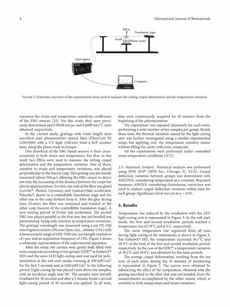
Figure 2: Schematic overview of the experimental setup used to measure the setting cuspal deformation and the temperature variation.
represent the strain and temperature sensitivity coefficientsof the FBG sensors [23]. For this work, they were previ-ously determined and 0.00118 nm/𝜇𝜀 and 0.0089 nm/∘C wereobtained, respectively.
In the current study, gratings with 1mm length wereinscribed onto photosensitive optical fiber (FiberCore PS1250/1500) with a UV light (248 nm) from a KrF excimerlaser, using the phase mask technique.
One drawback of the FBG based sensors is their cross-sensitivity to both strain and temperature. For that, in thisstudy two FBGs were used to measure the setting cuspaldeformation and the temperature variation. One of them,sensitive to strain and temperature variations, was placedperpendicular to the buccal cusp.This grating was previouslytensioned (about 500 𝜇𝜀), allowing the FBG sensor to detectnot only the increasing of the distance between the cusps butalso its approximation. For this, one side of the fiberwas glued(Loctite�, Henkel, Germany, and cyanoacrylate accelerator,Pekecho�, Spain) to a controllable translation stage and theother one to the cusp farthest from it. After the glue dryingtime (15min), the fiber was tensioned and bonded to theother cusp (nearest of the controllable translation stage). Anew waiting period of 15min was performed. The secondFBG was placed parallel to the first one, but not bonded norpretensioned, being only sensitive to temperature variations.The gratings’ wavelength was measured using a sm 125–500interrogation system (MicronOptics Inc., Atlanta, USA)withameasurement range of 1510–1590 nm,wavelength resolutionof 1 pm, and an acquisition frequency of 2Hz. Figure 2 showsa schematic representation of the experimental apparatus.
After the setup, the cavities were gently bulk filled withresin composite according to two groups (SDR� or Esthet∙X�HD) and the same LED light-curing unit was used for poly-merization in the soft-start mode, running at 650mW/cm2for the first 5 seconds and at 1200mW/cm2 in the followingperiod. Light-curing tip was placed 1mm above the samples,with an incidence angle near 90∘. The samples were initiallyirradiated for 30 seconds and after a 5-minute break a secondlight-curing period of 30 seconds was applied. In all tests,
data were continuously acquired for 10 minutes from thebeginning of the polymerization.
The experiment was repeated alternately for each resin,performing a total number of ten samples per group. Besidethese tests, the thermal variation caused by the light-curingunit was further investigated using a similar experimentalsetup, but applying only the temperature sensitive sensorwithout filling the cavity with resin composite.
All the experiments were performed under controlledroom temperature conditions (21∘C).
2.3. Statistical Analysis. Statistical analysis was performedusing SPSS 20.0� (SPSS Inc., Chicago, IL, EUA). Cuspaldeflection variation between groups was determined withANCOVA, considering temperature as a covariate. Repeatedmeasures ANOVA considering Greenhouse correction wasused to analyze cuspal deflection variation within time foreach group. Significance level was set at 𝛼 = 0.05.
3. Results
Temperature rise induced by the irradiation with the LEDlight-curing unit is represented in Figure 3. In the soft-startmode, the first and second irradiation periods reached atemperature rise of 7.9∘C and 8.3∘C, respectively.
The mean temperature rise registered from all testsduring light curing of the restorations is shown in Figure 4.For Esthet∙X� HD, the temperature increased 36.7∘C and28.9∘C at the final of the first and second irradiation period,respectively. In the case of the SDR�, a temperature variationof 38.2∘C and 30.8∘C was obtained for the same periods.
The average cuspal deformation, resulting from the tentests of each resin, during the 10 minutes of monitoringis represented in Figure 5. The curves were obtained bysubtracting the effect of the temperature, obtained with thegrating inscribed in the fiber that was not bonded, from themeasurements accomplished by the other sensor, which issensitive to both temperature and strain variations.

International Journal of Biomaterials 5
Table 2: Descriptive statistics analysis.
Time (min) Resin compositeDeformation
(𝜇𝜀) mean (Std.Deviation)
Minimum (𝜇𝜀) Maximum (𝜇𝜀)Cuspal
deflection (𝜇m)mean (Std.Deviation)
0.5min SDR� −646.3 (218.5) −457.3 −1195.5 −2.5 (0.8)Esthet∙ X�HD −1299.5 (190.5) −1077.9 −1582.0 −5.0 (0.7)
5.5min SDR� −2074.1 (137.1) −1910.5 −2371.7 −8.0 (0.5)Esthet∙ X�HD −2296.9 (256.5) −1786.7 −2608.6 −8.9 (1.0)
6min SDR� −1166.4 (286.4) −873.9 −1747.3 −4.5 (1.1)Esthet∙ X�HD −1751.4 (286.3) −1194.1 −2095.1 −6.8 (1.1)
10min SDR� −2001.2 (179.9) −1655.2 −2341.5 −7.8 (0.7)Esthet∙ X�HD −2277.2 (260.6) −1757.5 −2600.6 −8.8 (1.0)
8
6
4
2
0
0 2 4 6 8
Time (min)
Tem
pera
ture
var
iatio
n (∘
C)
Figure 3: Temperature variation induced by the LED light-curingunit.
Descriptive statistics of cuspal deflection in each periodis shown in Table 2. Between-subjects analysis of covariance(ANCOVA) is summarized in Table 3.
Over the time of polymerization, the two resin compos-ites presented a significant variation in material behavior(𝐹(1.42, 24.19) = 245.37, 𝑝 < 0.01, partial 𝜂2 = 0.935), asexpressed in Figure 5. After the first polymerization period,both groups present statistically significant cuspal inwardsdeformation in relation to any other measurement (𝑝 <0.01 for all comparisons between 0.5 minutes and 5.5, 6,and 10 minutes within each group). A similar behaviorwas found after the second polymerization period (6 to 10minutes) but with lower deformation (𝑝 < 0.01). OnlySDR presented no differences in cuspal deformation after thepostpolymerization clearance periods (𝑝 = 0.051 for the 5.5-and 10-minute comparison).
When light curing started, cuspal deformation experi-enced a slight expansion curve for both materials evaluated.This peak reached the maximum value at 0.05 minutes forboth resin composites. Esthet∙X� achieved in average 27.1𝜇𝜀and SDR� 91.8 𝜇𝜀. Thereafter, curves decreased (Figure 5).At 30 seconds, the mean values of cuspal deflection were
40
30
20
10
0
0 2 4 6 8 10
Time (min)
SDREsthet-X HD
Tem
pera
ture
var
iatio
n (∘
C)
Figure 4: Average temperature variation obtained during the lightcuring of the restorations with the SDR� and Esthet∙X�HD resins.
−1299.5𝜇𝜀 and −646.3 𝜇𝜀 for Esthet∙X� HD and SDR�,respectively (Figure 5 and Table 2). ANCOVA analysis con-sidering temperature as the covariate revealed a statisticallysignificant difference in cuspal deflection between the tworesin composite resins at 30 seconds of polymerization(𝐹(1, 17) = 52.69, 𝑝 < 0.01, partial 𝜂2 = 0.756). 𝑡-test forindependent samples equality ofmeans revealed deformationvalues statistically significantly higher in Esthet∙X� HDcompared to SDR� (Table 3).
In the mean time until the second polymerization (0.5to 5.5 minutes), Esthet∙X� HD curve deflection decreasedcontinuously until 2 minutes pass. From this moment, valuesremained constant until the terminus of this light-curingfree period, reaching a mean of −2296.9𝜇𝜀 at 5.5 minutes.The SDR� curve declines at a slower rate. At 5.5 minutes,samples restored with SDR� presented a cuspal deflectionof −2074.1𝜇𝜀 (Figure 5 and Table 2). There was a statisticallysignificant difference in cuspal deflection between two groupsat this point of the curing protocol (𝑝 = 0.016) (Table 3).

6 International Journal of Biomaterials
Table 3: Mean differences of deformation for samples restored with Esthet∙ X�HD and SDR�, for each time period (ANCOVA).
Time (min) Levene’s test (𝑝) 𝐹 𝑝
Mean difference(SDR - Esthet X)
(𝜇𝜀)Std. error difference
Mean difference(SDR - Esthet X)
(𝜇m)0.5 0.751 52.69 <0.01∗ 626.8 86.4 2.45.5 0.120 7.15 0.016∗ 255.6 95.6 1.06 0.733 21.64 <0.01∗ 601.4 129.3 2.310 0.620 7.37 0.015∗ 274.6 101.1 1.1∗Statistically significant differences.
500
0
−500
−1000
−1500
−2000
−2500
0 2 4 6 8 10
Time (min)
Def
orm
atio
n (𝜇𝜀)
SDREsthet-X HD
Figure 5: Average cuspal deformation induced by SDR� andEsthet∙X�HD resins during the 10minutes of real-timemonitoring.
During the second polymerization period, a new expan-sion peak occurred for both resin composites. After that, at 6minutes, Esthet∙X� HD curve presented −1751.4𝜇𝜀 of cuspaldeflection and SDR� −1166.3 𝜇𝜀 (Table 2 and Figure 5).According to that, between the beginning and the ending ofthe second polymerization period, cusps expanded approx-imately 560.1 𝜇𝜀 in samples restored with Esthet∙X� HDand 907.8𝜇𝜀 in SDR� samples. Mixed ANOVA consideringGreenhouse correction revealed a statistically significant dif-ference in cuspal deflection between the two resin compositesat 6 minutes (𝐹(1, 10) = 11.81, 𝑝 = 0.006, partial 𝜂2 = 0.542)(Table 3), meaning that cuspal deflection of Esthet∙X�HD atthis time point was significantly higher than SDR�.
In the period from 6 to 10 minutes, both deformationcurves decreased and for the last evaluated point the valuesremained constant (Figure 5). The average results obtainedwith Esthet∙X�HDand SDR�, at 10minutes, were−2277.2𝜇𝜀and−2001.2𝜇𝜀, respectively (Table 2).Therewas a statisticallysignificant difference in cuspal deflection between the twomaterials at 10 minutes (𝑝 = 0.015) (Table 3).
In order to determine the shortening distance betweenthe cusps (cuspal deflection), deformation expressed in
microstrain (𝜇𝜀) was converted tomicrometers (𝜇m), accord-ing to the following equation:
Cuspal deflection (𝜇m)
=
Deformation (𝜇𝜀) ∗ Initial distant between cuspids (3885 𝜇m)1 ∗ 10
6.
(3)
The average results obtained in micrometers (𝜇m) forthe more relevant periods of 0.5 and 10min were 5.0𝜇m(0.13%) and 8.8 𝜇m (0.23%) in the case of the Esthet∙X� HDand 2.5 𝜇m (0.06%) and 7.8 𝜇m (0.20%) for the SDR� resin,respectively.
4. Discussion
Despite numerous studies published, the highly complex phe-nomenon of polymerization shrinkage that develops in poly-meric dental restorative materials is not yet fully understoodand remains a significant clinical concern.This phenomenonbecomes even more complex when the composite is bondedinto cavities of variable configurations. For resin compositesbonded to enamel and dentin, polymerization shrinkage isconstrained and polymerization stress development becomesmore complex due to the generation of interfacial stressesusually unevenly distributed along the cavity walls and thebonded composite surfaces [10, 12].
The present study measured the tooth deformationinstead of shrinkage stresses, which can be assumed asan indirect indicator associated with internal stress [3, 4].Regrettably, the methods most commonly used for cuspaldeflection monitoring depend primarily on measuring thedifference between precuring and postcuring values, but theydo not provide detailed data regarding how this phenomenonoccurs in a real-time process [9]. In fact, themethods of mea-surement of cusp deflection during composite restorationhave been reported to produce considerably varying results.When applying contact methods, the use of reproduciblereference points on the cusps seems to be critical to avoiderroneous results between samples [5].With FBG sensors thispoint is not an issue since the measurement of dimensionalchanges is made by the Bragg sensor, which is not directlyattached to the tooth structure. Therefore, it can be expectedthat under identical experimental conditions, cusp deflectionmeasurements for the same restoration protocol can resultin different data according to the experimental device usedand the inherent tooth compliance. Caution is needed when

International Journal of Biomaterials 7
comparing results across studies asmean cuspal deflections ofup to 50 𝜇m were recorded using a wide range of techniques[2–4, 6–9, 11].
Human molars were used to assess cuspal deflectionusing FBG sensors. A relatively high variation among teethdimensions in experimental studies may affect the outcomes,impairing the comparison between studies with the samepurpose. Despite the careful attempts to achieve standard-ization of cavity preparation, some inevitable discrepanciesmay be present when natural teeth are used. In this study,molar teeth were selectively allocated in order to promotea maximum difference of 5% in BPW between the groups.Despite tooth standardization, the dispersion values (SD) ofeach group reported high variability among samples, whichcould be due to the employment of natural teeth with non-homogenous morphological and structural characteristics aspreviously described for other experimental models usingnatural teeth. In fact, it was not possible to determine theresidual thickness of both dentin and enamel, which inconjunction with slight differences in the amount of theresin used to fill the tooth could compromise the compliancebehavior and consequently induce different cuspal displace-ments. Notwithstanding this, molar teeth choice togetherwith the large Class II MOD cavity design used in thepresent study has the advantage of wider surface area forfiber bonding, contrarily to premolars mostly used in otherstudies [2, 6, 7] while providing an in vitro simulation of someclinical situations of weakened remaining tooth structure,favorable to cuspal deflection during restorative procedures.Large deflections for MODs cavities can be explained by theloss of tooth rigidity when the marginal ridges are removed[3]. Additionally, the cusps that remain after an MOD cavitypreparation were reported to act as a cantilever beam underocclusal load, which increases with cavity depth, while theprepared cavity floor acts as a fulcrum for cusp bending.Biomechanical principles refer to the fact that deflection isproportional to the cubed power of the length and to theinverse of the thickness of the cantilever cusp cubed [7, 8].
FBG sensors methodology allowed a real-time monitor-ing of the deformations occurring during resin compositecuring as well as the thermal behavior during this proce-dure [17, 20]. For cavity preparations restored with resincomposites under shrinkage, loadings and displacements willoccur in multiple directions. While knowing that shrinkingcomposite develops a triaxial stress state, as reported withfinite element analysis [10, 12], our measurements registeredonly the forces developing uniaxially in the long axis ofeach tooth, expressed as a single value. Nevertheless, theuse of a standardized tooth cavity allowed a well-balancedhomogenization of compliance, cavity configuration, andcomposite volume, which have been found to be the mostcritical variables related to stress development in a clinicalsituation [10].
The present study compared the marketed low-shrinkageflowable RBC SDR� with a conventional microhybrid RBCEsthet∙X� HD assessing their performance in bulk filladhesive MOD molar restorations by measuring cuspaldeformation with FBG sensors during a two-step curingprotocol in order to deliver a reliable energy density to
the restoration. Although conventional microhybrid RBCshave restricted indications for bulk fill placement techniqueand SDR� application advocates the use of a microhybridresin composite for the final covering layer, the purposewas to equalize the restorative protocol in order to isolateand evaluate the individual biomechanical behavior of bothmaterials in similar one-increment situations related to thepotential advantage evocated for the “low-shrinkage” one.Significant differences were found between the twomaterials;therefore the null hypothesis was rejected.
The greatest difference was detected at the end of thefirst 30 seconds curing period. At this point, Esthet∙X� HDinduced significantly more deformation (meaning cuspaldeflection) than SDR�, which could enhance faster andhigher stress development at the tooth/restoration adhesiveinterface. At the end of the subsequent five-minute pauseperiod both RBCs reached higher shrinkage values, althoughthe polymerization kinetics of SDR� seems to developmore gradually than that achieved by Esthet∙X� HD. Thismay be related to the functionality of the polymerizationmodulator incorporated in SDR� resin matrix. In theory,when this modulator interacts with the photoinitiator (cam-phorquinone) the polymerization kinetics can be controlledby delaying the gel point, by slowing the rate of polymer-ization and elastic modulus development, and by reducingpolymer cross-linking and, consequently, shrinkage stress[16, 24].
Cuspal deformation curves showed three expansionpeaks during the experimental curing period for both resincomposites. As soon as the first light irradiation periodstarted, a discrete expansion and transitory peak weredetected. However, at the beginning of the second curinglight exposure, an expressive and prolonged expansion peakcould be observed during all the 30-second irradiation time.These events can be interpreted as the thermal expansioneffect caused either by the heat from the curing light or bythe exothermic nature of the free radical polymerization ofdimethacrylate monomers, as pointed out by other authors[4, 19, 20]. When polymerization shrinkage exceeds thermalexpansion in the first expansion peak, fast overall materialshrinking takes place, evidenced by a sudden increase con-traction strain [19, 20]. In opposite, the persistent expansionpeak observed along the second irradiation period occurswhen a considerable cross-linking of the monomer hasalready been achieved, meaning that the thermal effect hasgreater relative influence on the dimensional behavior of bothresin composites. Additionally, the inherent temperaturerise can be implied in the resin composite glass transitiontemperature attainment, at which the polymer goes fromthe glassy to the rubbery state [25, 26]. If this occurs, asignificant increase in polymer chain mobility is expected,favoring additional cross-linking and stress relief [27]. Thisexpansion was significantly more pronounced for samplesrestored with SDR� than Esthet∙X� HD.This can be furtherexplained by the lower filler content exhibited by SDR�, asan inverse linear relationship between coefficient of linearthermal expansion and the filler volume fraction of theresin composite has been observed by different researchers[25]. Another intermediate and discrete expansion peak was

8 International Journal of Biomaterials
obtained immediately few seconds before the end of thefirst irradiation period. Possibly, a cumulative thermal effectinduced by the high power density emitted by the curing unitat this point leads to the development of a new expansionphase. These thermal expansions can be considered internalconstraints that will be added to the total amplitude internalstress [1].
In the last measurement (10 minutes), the mean totalcuspal deflection was 8.8𝜇m (0.23%) and 7.8 𝜇m (0.20%)for the maxillary molar teeth restored with Esthet∙X� HDand SDR� resins, respectively. SDR� presented significantlyless final cuspal deflection than Esthet∙X� HD. Indeed, inthe few studies available concerning SDR�, polymerizationstress was reported to be considerably lower than that ofconventional flowable resin composites, being comparable toother marketed low shrinking resin composites [8, 16] andmarginal integrity appeared as good as that obtained with aconventionally layered resin composite [8]. Previous studiesshowed volumetric polymerization shrinkage around 3% forEsthet∙X� [28] and around 3.1% for SDR� [15]. Differencesbetween those findings and the results of the present workcould be due to the fact that shrinkage stress developmentis not exclusively associated with the volumetric shrinkagebehavior. Moorthy et al. [8] showed that two bulk fill flowableRBC bases (SDR� and x-tra base) have significantly reducedcuspal deflection during light irradiation when compared toa conventional RBC (GrandioSO), reporting a total meancuspal deflection of 4.63 𝜇m (1.19), 4.73𝜇m (0.99), and11.26 𝜇m(2.56) for SDR�, x-tra base, andGrandioSO, respec-tively. Other recent studies conducted by Taubock et al. [24]reported that SDR� generated significantly lower shrinkageforces compared with the microhybrid Esthet∙X� HD whenirradiation was performed at continuous high irradiance,even though axial polymerization shrinkage of the SDRcomposite exceeded that of the microhybrid. Nevertheless,the authors revealed no benefit of SDR regarding shrinkageforce generation when modulated curing protocols with lowinitial irradiance were applied, such as in the soft-start mode,arguing a low responsiveness of SDR to modulated photoac-tivation due to the predominant effect of the polymerizationmodulator on reaction kinetics and stress development. Inthe present study, to control shrinkage-induced tensions,both resin composites were polymerized using a soft-startcuring mode, with the expectation that this approach couldreduce cuspal movement and improvement of restorationinterfacial integrity. One can speculate that if a continuoushigh level curing irradiance had been used, higher cuspaldisplacement could have taken place, particularly in themicrohybrid Esthet∙X�HD samples.
Some drawbacks can be pointed out to the methodologyemployed in this study concerning FBG sensors. Cross-sensitivity to both strain and temperature requires specifictechniques to compensate for the thermal influence, whichwas dealt with as an additional Bragg grating. The infor-mation obtained is wavelength encoded and extracting realinformation from the wavelength shift involves the develop-ment of particular applications. Other disadvantages consiston the inherent fiber fragility, which makes the manipulationand the bonding of the fiber to the teeth difficult [17].
Several authors have developed in vitro simulation modelsto determine the shrinkage stress or cuspal deflection ofRBC materials. However, the limitation of some of thosein vitro experiments is related to the simplicity of themodel designs, using frequently, parallel walls that ignorenonaligned stress development linked tomore complex cavitygeometries and to the differential compliance of the testingsystems, which significantly influences stress development,particularly depending on C-factor and resin compositevolume [10]. Also, they do not allow the acquisition ofinformation in a continuous and real-time mode [7, 29, 30],which was overcome by the methodology used in the presentstudy. Another relevant advantage of the FBG is the highresolution obtained in the cuspal displacement monitoring.Since the wavelength resolution of the interrogation systemis 1 pm, a variation of 0.85 𝜇𝜀 can be noticed. Considering theinitial distance between the cusps of 3885 𝜇m, it correspondsto an absolute resolution of 0.003 𝜇m. During the last fewyears, research work devoted to studying and exploring thepotential application of fiber optic technology in biomedicinehas increased significantly [20].
To the extent of the knowledge of the authors concerningthe scientific published literature, this is the first known studyto measure tooth cuspal deflection with fiber Bragg gratingsensors. Fiber Bragg sensors can be extensively appliedin future studies, comparing different protocols or clinicalmodified variables useful for shrinkage stress management inclinical practice.
5. Conclusion
Within the conditions of this research protocol, SDR�polymerization kinetics induced less stress to dental structurethanEsthet∙X�HD, as themean cuspal deflection valueswerestatistically different between the two resin composites.
Despite the limitations of this in vitro study the opticalFBG sensors seem to be a suitable measurement method toevaluate tooth dimensional changes related to cuspal deflec-tion induced by resin composite polymerization shrinkage,with some advantages over other techniques, namely, contin-uous real-time assessment of tooth biomechanical behavior.
Competing Interests
The authors declare that they have no competing interests.
References
[1] J. L. Ferracane, “Buonocore lecture. Placing dental com-posites—a stressful experience,”Operative Dentistry, vol. 33, no.3, pp. 247–257, 2008.
[2] M.-R. Lee, B.-H. Cho, H.-H. Son, C.-M. Um, and I.-B. Lee,“Influence of cavity dimension and restoration methods on thecusp deflection of premolars in composite restoration,” DentalMaterials, vol. 23, no. 3, pp. 288–295, 2007.
[3] D. Tantbirojn, A. Versluis, M. R. Pintado, R. DeLong, andW. H. Douglas, “Tooth deformation patterns in molars aftercomposite restoration,”Dental Materials, vol. 20, no. 6, pp. 535–542, 2004.

International Journal of Biomaterials 9
[4] Y. Kwon, J. Ferracane, and I.-B. Lee, “Effect of layeringmethods,composite type, and flowable liner on the polymerizationshrinkage stress of light cured composites,” Dental Materials,vol. 28, no. 7, pp. 801–809, 2012.
[5] W. M. Palin, G. J. P. Fleming, H. Nathwani, F. J. T. Burke, andR. C. Randall, “In vitro cuspal deflection and microleakageof maxillary premolars restored with novel low-shrink dentalcomposites,” Dental Materials, vol. 21, no. 4, pp. 324–335, 2005.
[6] G. J. P. Fleming, S. Khan,O.Afzal,W.M. Palin, and F. J. T. Burke,“Investigation of polymerisation shrinkage strain, associatedcuspal movement and microleakage of MOD cavities restoredincrementally with resin-based composite using an LED lightcuring unit,” Journal of Dentistry, vol. 35, no. 2, pp. 97–103, 2007.
[7] R. El-Helali, A. H. Dowling, E. L. McGinley, H. F. Duncan, andG. J. P. Fleming, “Influence of resin-based composite restorationtechnique and endodontic access on cuspal deflection andcervical microleakage scores,” Journal of Dentistry, vol. 41, no.3, pp. 216–222, 2013.
[8] A. Moorthy, C. H. Hogg, A. H. Dowling, B. F. Grufferty,A. R. Benetti, and G. J. P. Fleming, “Cuspal deflection andmicroleakage in premolar teeth restored with bulk-fill flowableresin-based composite base materials,” Journal of Dentistry, vol.40, no. 6, pp. 500–505, 2012.
[9] H. H. Hamama, N. M. Zaghloul, O. B. Abouelatta, and A. E.El-Embaby, “Determining the influence of flowable compositeresin application on cuspal deflection using a computerizedmodification of the strain gaugemethod,”TheAmerican Journalof Esthetic Dentistry, vol. 1, no. 1, pp. 48–59, 2011.
[10] L. C.C. Boaro,W.C. Brandt, J. B. C.Meira, F. P. Rodrigues,W.M.Palin, and R. R. Braga, “Experimental and FE displacement andpolymerization stress of bonded restorations as a function of theC-Factor, volume and substrate stiffness,” Journal of Dentistry,vol. 42, no. 2, pp. 140–148, 2014.
[11] J. Park, J. Chang, J. Ferracane, and I. B. Lee, “How shouldcomposite be layered to reduce shrinkage stress: incrementalor bulk filling?” Dental Materials, vol. 24, no. 11, pp. 1501–1505,2008.
[12] F. P. Rodrigues, R. G. Lima, A. Muench, D. C. Watts, and R. Y.Ballester, “A method for calculating the compliance of bonded-interfaces under shrinkage: validation for Class I cavities,”Dental Materials, vol. 30, no. 8, pp. 936–944, 2014.
[13] N. Ilie, E. Jelen, and R. Hickel, “Is the soft-start polymerisationconcept still relevant for modern curing units?” Clinical OralInvestigations, vol. 15, no. 1, pp. 21–29, 2011.
[14] J. G. Leprince, W. M. Palin, J. Vanacker, J. Sabbagh, J. Devaux,andG. Leloup, “Physico-mechanical characteristics of commer-cially available bulk-fill composites,” Journal of Dentistry, vol.42, no. 8, pp. 993–1000, 2014.
[15] J. Burgess and D. Cakir, “Comparative properties of low-shrinkage composite resins,” Compendium Continuing Educa-tion in Dentistry, vol. 31, no. 2, pp. 10–15, 2010.
[16] N. Ilie and R. Hickel, “Investigations on a methacrylate-basedflowable composite based on the SDR� technology,” DentalMaterials, vol. 27, no. 4, pp. 348–355, 2011.
[17] N. Alberto, L. Carvalho, H. Lima, P. Antunes, R. Nogueira, andJ. L. Pinto, “Characterization of different water/powder ratiosof dental gypsum using fiber bragg grating sensors,” DentalMaterials Journal, vol. 30, no. 5, pp. 700–706, 2011.
[18] M. S. Milczewski, J. C. C. da Silva, I. Abe et al., “Determinationof setting expansion of dental materials using fibre opticalsensing,”Measurement Science and Technology, vol. 17, no. 5, pp.1152–1156, 2006.
[19] M. S. Milczewski, J. C. C. Silva, A. S. Paterno, F. Kuller, and H.J. Kalinowski, “Measurement of composite shrinkage using afibre optic Bragg grating sensor,” Journal of Biomaterials Science,Polymer Edition, vol. 18, no. 4, pp. 383–392, 2007.
[20] E. J. Anttila, O. H. Krintila, T. K. Laurila, L. V. J. Lassila, P. K.Vallittu, and R. G. R. Hernberg, “Evaluation of polymerizationshrinkage and hydroscopic expansion of fiber-reinforced bio-composites using optical fiber Bragg grating sensors,” DentalMaterials, vol. 24, no. 12, pp. 1720–1727, 2008.
[21] S. M. M. Quintero, A. M. B. Braga, H. I. Weber, A. C. Bruno,and J. F. D. F. Araujo, “Amagnetostrictive composite-fiber bragggrating sensor,” Sensors, vol. 10, no. 9, pp. 8119–8128, 2010.
[22] H. Li, H. Yang, E. Li, Z. Liu, and K. Wei, “Wearable sensorsin intelligent clothing for measuring human body temperaturebased on optical fiber Bragg grating,”Optics Express, vol. 20, no.11, pp. 11740–11752, 2012.
[23] A. Othonos and K. Kali, Fiber Bragg Gratings—Fundamentalsand Applications in Telecommunications and Sensing, ArtechHouse, 1999.
[24] T. T. Taubock, A. J. Feilzer, W. Buchalla, C. J. Kleverlaan, I.Krejci, and T. Attin, “Effect of modulated photo-activation onpolymerization shrinkage behavior of dental restorative resincomposites,” European Journal of Oral Sciences, vol. 122, no. 4,pp. 293–302, 2014.
[25] I. Sideridou, D. S. Achilias, and E. Kyrikou, “Thermal expansioncharacteristics of light-cured dental resins and resin compos-ites,” Biomaterials, vol. 25, no. 15, pp. 3087–3097, 2004.
[26] R. Walter, E. J. Swift Jr., H. Sheikh, and J. L. Ferracane, “Effectsof temperature on composite resin shrinkage,” QuintessenceInternational, vol. 40, no. 10, pp. 843–847, 2009.
[27] E. K. Viljanen, M. Skrifvars, and P. K. Vallittu, “Dendriticcopolymers and particulate filler composites for dental appli-cations: degree of conversion and thermal properties,” DentalMaterials, vol. 23, no. 11, pp. 1420–1427, 2007.
[28] W. Lien and K. S. Vandewalle, “Physical properties of a newsilorane-based restorative system,”Dental Materials, vol. 26, no.4, pp. 337–344, 2010.
[29] F. Goncalves, C. S. Pfeifer, J. L. Ferracane, and R. R. Braga,“Contraction stress determinants in dimethacrylate compos-ites,” Journal of Dental Research, vol. 87, no. 4, pp. 367–371, 2008.
[30] L. C. C. Boaro, F. Gonalves, T. C. Guimaraes, J. L. Ferracane, A.Versluis, and R. R. Braga, “Polymerization stress, shrinkage andelastic modulus of current low-shrinkage restorative compos-ites,” Dental Materials, vol. 26, no. 12, pp. 1144–1150, 2010.

Submit your manuscripts athttp://www.hindawi.com
ScientificaHindawi Publishing Corporationhttp://www.hindawi.com Volume 2014
CorrosionInternational Journal of
Hindawi Publishing Corporationhttp://www.hindawi.com Volume 2014
Polymer ScienceInternational Journal of
Hindawi Publishing Corporationhttp://www.hindawi.com Volume 2014
Hindawi Publishing Corporationhttp://www.hindawi.com Volume 2014
CeramicsJournal of
Hindawi Publishing Corporationhttp://www.hindawi.com Volume 2014
CompositesJournal of
NanoparticlesJournal of
Hindawi Publishing Corporationhttp://www.hindawi.com Volume 2014
Hindawi Publishing Corporationhttp://www.hindawi.com Volume 2014
International Journal of
Biomaterials
Hindawi Publishing Corporationhttp://www.hindawi.com Volume 2014
NanoscienceJournal of
TextilesHindawi Publishing Corporation http://www.hindawi.com Volume 2014
Journal of
NanotechnologyHindawi Publishing Corporationhttp://www.hindawi.com Volume 2014
Journal of
CrystallographyJournal of
Hindawi Publishing Corporationhttp://www.hindawi.com Volume 2014
The Scientific World JournalHindawi Publishing Corporation http://www.hindawi.com Volume 2014
Hindawi Publishing Corporationhttp://www.hindawi.com Volume 2014
CoatingsJournal of
Advances in
Materials Science and EngineeringHindawi Publishing Corporationhttp://www.hindawi.com Volume 2014
Smart Materials Research
Hindawi Publishing Corporationhttp://www.hindawi.com Volume 2014
Hindawi Publishing Corporationhttp://www.hindawi.com Volume 2014
MetallurgyJournal of
Hindawi Publishing Corporationhttp://www.hindawi.com Volume 2014
BioMed Research International
MaterialsJournal of
Hindawi Publishing Corporationhttp://www.hindawi.com Volume 2014
Nano
materials
Hindawi Publishing Corporationhttp://www.hindawi.com Volume 2014
Journal ofNanomaterials
Related Documents