Hindawi Publishing Corporation Advances in Materials Science and Engineering Volume 2013, Article ID 748294, 13 pages http://dx.doi.org/10.1155/2013/748294 Research Article Behavior of Concrete Columns Repaired with Polymer Mortar and Epoxy Fiber Panel Sungnam Hong and Sun-Kyu Park Department of Civil and Environmental Engineering, Sungkyunkwan University, Suwon 440-746, Republic of Korea Correspondence should be addressed to Sun-Kyu Park; [email protected] Received 12 November 2012; Accepted 30 January 2013 Academic Editor: Md Mainul Islam Copyright © 2013 S. Hong and S.-K. Park. is is an open access article distributed under the Creative Commons Attribution License, which permits unrestricted use, distribution, and reproduction in any medium, provided the original work is properly cited. Underwater structures are not easy to check for the degree of damage or to repair and strengthen damaged regions. Even during repair and strengthening, quality control is very difficult, because the work is done under water. Moreover, underwater structures severely deteriorate, owing to special environmental conditions. If this deterioration continues, the structures face serious structural problems, because of the corrosion of steel rods and the loss of concrete sections. Repairing or strengthening underwater structures requires effective, economic underwater repair and reinforcement techniques that allow the same working conditions as on the ground while maintaining dry condition for the repair sections. However, systematic studies on the repair and strengthening techniques for underwater structures are insufficient. is study proposes a new repair method for underwater structures, which applies epoxy fiber panel forms and shear connectors. To demonstrate the repair effects, this study compared and evaluated the failure modes and repair effects by the surface condition of repair sections, by applying various repair methods, in consideration of the ground and underwater conditions. 1. Introduction When concrete structures are constructed in a river, lake, or sea, a part of the structure is placed under water, and the underwater structures are subjected to damages such as concrete spalling and exfoliation, due to aging, faulty construction, and various deterioration factors [1]. Such structures urgently need repairs and reinforcements. In par- ticular, the substructures of bridges in water are subjected to damages by such environmental factors as the scouring of foundations by water flow, erosion of members, and the corrosion of steel rods [2], in addition to the damages that may occur to structures above ground. Structural engineers have extensive experience of repair- ing concrete structures above water [3–6]. e conventional approach to the repair of reinforced concrete columns that have shallow damages, however, is to use patch repair for the damaged zones where cracking and spalling occur [7, 8]. For patch repair to be structurally effective, the appropriate material should be applied in the damaged concrete section. A limited range of materials is available for use in underwater repair. ey can be divided into two mortar types: cementitious and resin based. Generally, normal epoxy or polyester resins are unsuitable for underwater use, as they oſten fail to bond to the damaged concrete and can be adversely affected by reaction between the hardener and the water [9]. However, cementitious mortars can range from conventional mortars and grouts to materials with greatly enhanced properties achieved by the use of admixtures. In particular, the use of polymers can result in cohesiveness, high rates of strength gain, greater workability, resistance to washout of cement, and reduction in bleed and shrinkage [10–12]. From these advantages, polymer mortar has been utilized in a range of mortar and concrete repair and primary construction applications [13–15]. For effective repair and reinforcement of underwater structures, the damaged regions must be maintained in dry condition. However, installing coffers and caissons for partial defects under water requires a long period of work, much manpower, and heavy equipment, so causing much loss

Welcome message from author
This document is posted to help you gain knowledge. Please leave a comment to let me know what you think about it! Share it to your friends and learn new things together.
Transcript
Hindawi Publishing CorporationAdvances in Materials Science and EngineeringVolume 2013, Article ID 748294, 13 pageshttp://dx.doi.org/10.1155/2013/748294
Research ArticleBehavior of Concrete Columns Repaired with PolymerMortar and Epoxy Fiber Panel
Sungnam Hong and Sun-Kyu Park
Department of Civil and Environmental Engineering, Sungkyunkwan University, Suwon 440-746, Republic of Korea
Correspondence should be addressed to Sun-Kyu Park; [email protected]
Received 12 November 2012; Accepted 30 January 2013
Academic Editor: Md Mainul Islam
Copyright © 2013 S. Hong and S.-K. Park. This is an open access article distributed under the Creative Commons AttributionLicense, which permits unrestricted use, distribution, and reproduction in any medium, provided the original work is properlycited.
Underwater structures are not easy to check for the degree of damage or to repair and strengthen damaged regions. Even duringrepair and strengthening, quality control is very difficult, because the work is done under water. Moreover, underwater structuresseverely deteriorate, owing to special environmental conditions. If this deterioration continues, the structures face serious structuralproblems, because of the corrosion of steel rods and the loss of concrete sections. Repairing or strengthening underwater structuresrequires effective, economic underwater repair and reinforcement techniques that allow the same working conditions as on theground while maintaining dry condition for the repair sections. However, systematic studies on the repair and strengtheningtechniques for underwater structures are insufficient. This study proposes a new repair method for underwater structures, whichapplies epoxy fiber panel forms and shear connectors. To demonstrate the repair effects, this study compared and evaluated thefailure modes and repair effects by the surface condition of repair sections, by applying various repair methods, in consideration ofthe ground and underwater conditions.
1. Introduction
When concrete structures are constructed in a river, lake,or sea, a part of the structure is placed under water, andthe underwater structures are subjected to damages suchas concrete spalling and exfoliation, due to aging, faultyconstruction, and various deterioration factors [1]. Suchstructures urgently need repairs and reinforcements. In par-ticular, the substructures of bridges in water are subjectedto damages by such environmental factors as the scouringof foundations by water flow, erosion of members, and thecorrosion of steel rods [2], in addition to the damages thatmay occur to structures above ground.
Structural engineers have extensive experience of repair-ing concrete structures above water [3–6]. The conventionalapproach to the repair of reinforced concrete columns thathave shallow damages, however, is to use patch repair forthe damaged zones where cracking and spalling occur [7, 8].For patch repair to be structurally effective, the appropriatematerial should be applied in the damaged concrete section.
A limited range of materials is available for use inunderwater repair. They can be divided into two mortartypes: cementitious and resin based. Generally, normal epoxyor polyester resins are unsuitable for underwater use, asthey often fail to bond to the damaged concrete and can beadversely affected by reaction between the hardener and thewater [9]. However, cementitious mortars can range fromconventional mortars and grouts to materials with greatlyenhanced properties achieved by the use of admixtures. Inparticular, the use of polymers can result in cohesiveness,high rates of strength gain, greater workability, resistance towashout of cement, and reduction in bleed and shrinkage[10–12]. From these advantages, polymer mortar has beenutilized in a range of mortar and concrete repair and primaryconstruction applications [13–15].
For effective repair and reinforcement of underwaterstructures, the damaged regions must be maintained in drycondition. However, installing coffers and caissons for partialdefects under water requires a long period of work, muchmanpower, and heavy equipment, so causing much loss

2 Advances in Materials Science and Engineering
Inlet Outlet
Rubber
Adhesive epoxy
Set anchor
Underwater structure
Shearconnector
Deterioration of underwaterstructure
Surface processing of repairsections
Production of fiber panel forms andinstallation of shear connectors
Installation of forms and epoxywork
Removal of water from the forms
Injection of patch repairmaterials
Curing
Formwork
Repair material
Figure 1: Schematic diagram of the newly proposed repair method.
in time and money [16]. Therefore, we need effective andeconomic underwater repair and reinforcement techniquesthat allow working in the same conditions as on the groundwhile maintaining a dry condition. However, systematicstudies on the repairs and reinforcements of underwaterstructures are insufficient.
Accordingly, this study proposes a repair method forunderwater structures, which applies epoxy fiber panel formsand shear connectors. To demonstrate the repair effects,this study compared and evaluated the repair effects, byapplying various repair methods, in consideration of variousunderwater and ground conditions.
2. Newly Proposed Underwater Repair Method
Existing repair methods for underwater structures can belargely classified into three groups, as shown below [17].
(1) Repairing the damaged sections after installing cof-fers.
(2) Repairing by installing underwater caissons.(3) Repairing with underwater repair materials by divers.
Repair methods that use coffers and caissons greatlyincrease time and construction cost, includingmaterials cost,so they are uneconomical for partial repair works. Further-more, the direct repairmethod by divers is also inappropriate,because it causes environmental problems such as the leakageof materials, quality control is difficult, and effective repairwork is impossible.
The underwater repair method proposed by this studyhas been newly developed to apply to underwater structureswith deteriorations such as concrete spalling and exfoliation,cracks, and corrosion of steel rods. Because the outsidewater is perfectly blocked by fiber panel forms, underwaterepoxies, and rubber packings, while the damaged sections are
repaired [18], this method maximizes the repair effects andenables economical work. Furthermore, the shear connectorsinstalled on the repair sections give shear resistance atinterfaces and prevent the elimination of repair materials;anchor bolts fix the forms, to provide binding force. Thework procedure and a schematic diagram of the proposedunderwater repair method are shown in Figure 1.
3. Experimental Program
3.1. Test Variables. To evaluate the performance of theproposed underwater repair method, control columns andrepaired columns were produced, as shown in Table 1. Therepaired columns were produced under water and aboveground, to evaluate the effects of different working con-ditions. The proposed underwater repair method used theepoxy fiber panels and shear connectors in numbers 19 to 22in Table 1.
It should be noted that the test columns were planned forthe pilot test in the laboratory. Therefore, full-scale field testsshould be conducted, to derive a general application for theproposed repair system.
3.2. Material Properties. The concrete mix proportion for thecontrol and repaired columns are shown in Table 2. For thecompressive strength and splitting tensile strength of concreteby atmospheric curing and water curing of concrete aged 28days, three columns were produced and tested, and the meanvalues are summarized in Table 2.
For repair materials, inorganic polymer mortar with apolymer/cement ratio of 20%, which was specially manufac-tured for underwater use, was used. The strength character-istics of the underwater repair material were determined bycompressive strength test and splitting tensile strength test
Advances in Materials Science and Engineering 3
(a) Forms after pouring concrete (b) Shape of columns
(c) Chipping of concrete (d) Shear connectors and anchor bolts
(e) Assembly of epoxy fiber panel (f) Injection of repair materials
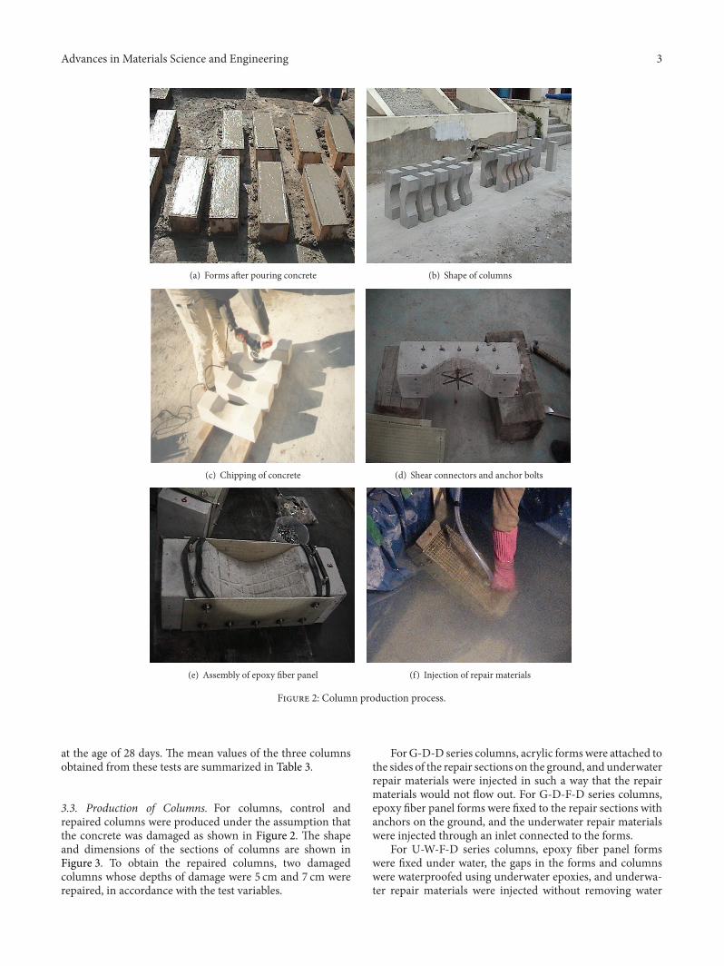
Figure 2: Column production process.
at the age of 28 days. The mean values of the three columnsobtained from these tests are summarized in Table 3.
3.3. Production of Columns. For columns, control andrepaired columns were produced under the assumption thatthe concrete was damaged as shown in Figure 2. The shapeand dimensions of the sections of columns are shown inFigure 3. To obtain the repaired columns, two damagedcolumns whose depths of damage were 5 cm and 7 cm wererepaired, in accordance with the test variables.
ForG-D-D series columns, acrylic formswere attached tothe sides of the repair sections on the ground, and underwaterrepair materials were injected in such a way that the repairmaterials would not flow out. For G-D-F-D series columns,epoxy fiber panel forms were fixed to the repair sections withanchors on the ground, and the underwater repair materialswere injected through an inlet connected to the forms.
For U-W-F-D series columns, epoxy fiber panel formswere fixed under water, the gaps in the forms and columnswere waterproofed using underwater epoxies, and underwa-ter repair materials were injected without removing water
4 Advances in Materials Science and Engineering
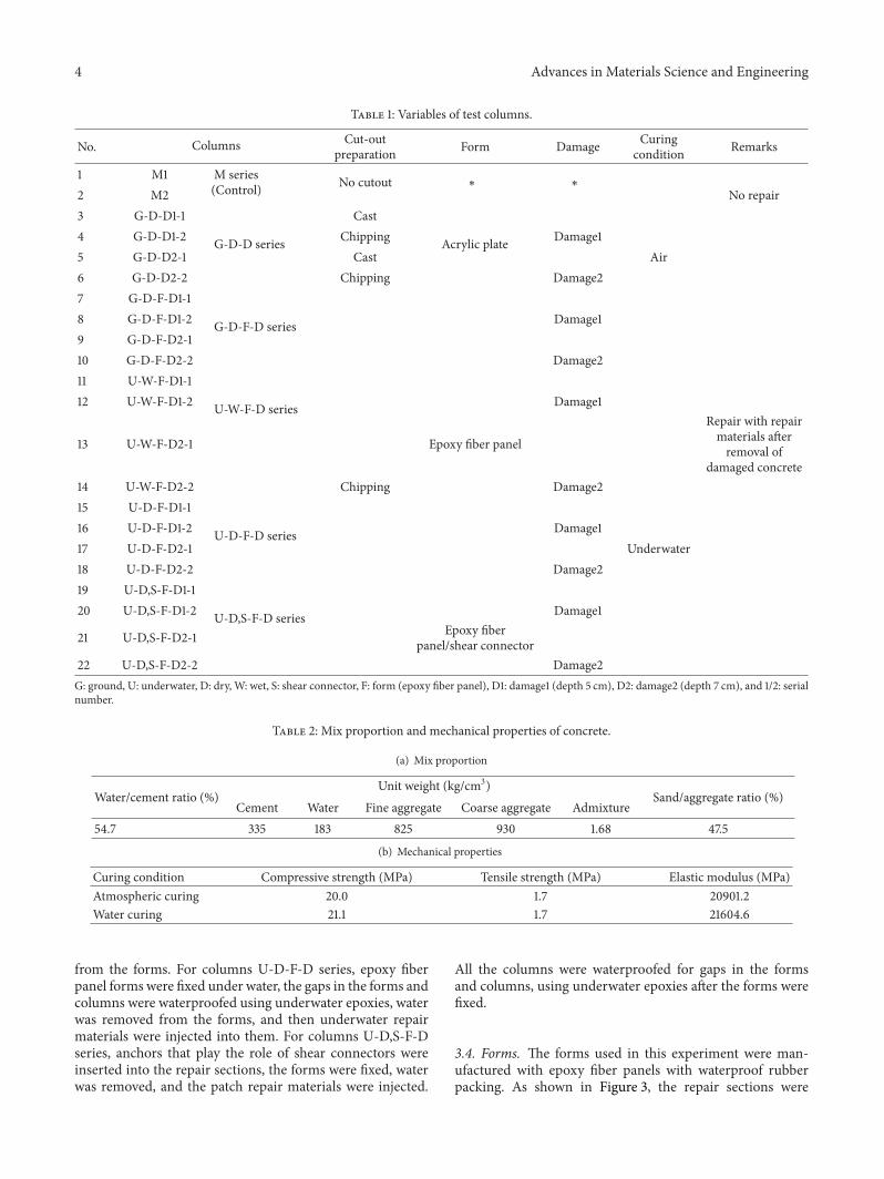
Table 1: Variables of test columns.
No. Columns Cut-outpreparation Form Damage Curing
condition Remarks
1 M1 M series(Control) No cutout ∗ ∗
2 M2 No repair3 G-D-D1-1 Cast4 G-D-D1-2 G-D-D series Chipping Acrylic plate Damage15 G-D-D2-1 Cast Air6 G-D-D2-2 Chipping Damage27 G-D-F-D1-18 G-D-F-D1-2 G-D-F-D series Damage19 G-D-F-D2-110 G-D-F-D2-2 Damage211 U-W-F-D1-112 U-W-F-D1-2 U-W-F-D series Damage1
13 U-W-F-D2-1 Epoxy fiber panel
Repair with repairmaterials afterremoval of
damaged concrete14 U-W-F-D2-2 Chipping Damage215 U-D-F-D1-116 U-D-F-D1-2 U-D-F-D series Damage117 U-D-F-D2-1 Underwater18 U-D-F-D2-2 Damage219 U-D,S-F-D1-120 U-D,S-F-D1-2 U-D,S-F-D series Damage1
21 U-D,S-F-D2-1 Epoxy fiberpanel/shear connector
22 U-D,S-F-D2-2 Damage2G: ground, U: underwater, D: dry, W: wet, S: shear connector, F: form (epoxy fiber panel), D1: damage1 (depth 5 cm), D2: damage2 (depth 7 cm), and 1/2: serialnumber.
Table 2: Mix proportion and mechanical properties of concrete.
(a) Mix proportion
Water/cement ratio (%)Unit weight (kg/cm3)
Cement Water Fine aggregate Coarse aggregate AdmixtureSand/aggregate ratio (%)
54.7 335 183 825 930 1.68 47.5
(b) Mechanical properties
Curing condition Compressive strength (MPa) Tensile strength (MPa) Elastic modulus (MPa)Atmospheric curing 20.0 1.7 20901.2Water curing 21.1 1.7 21604.6
from the forms. For columns U-D-F-D series, epoxy fiberpanel forms were fixed under water, the gaps in the forms andcolumns were waterproofed using underwater epoxies, waterwas removed from the forms, and then underwater repairmaterials were injected into them. For columns U-D,S-F-Dseries, anchors that play the role of shear connectors wereinserted into the repair sections, the forms were fixed, waterwas removed, and the patch repair materials were injected.
All the columns were waterproofed for gaps in the formsand columns, using underwater epoxies after the forms werefixed.
3.4. Forms. The forms used in this experiment were man-ufactured with epoxy fiber panels with waterproof rubberpacking. As shown in Figure 3, the repair sections were

Advances in Materials Science and Engineering 5
250
Epoxy fiber panel
Cavity:50, 70
Cavity:50, 70
250
Acrylic plate
Form: epoxy fiber panelForm: acrylic plateControl150
150
500
Concrete
Strain gauge
75
75
1010
A1A2
S5S4S3 S2 S1
32.5@4 = 13
10
10
10
10
10
10
1010
15
20
20
20
20
20
15
Shearconnector
20
10
10
Repairmortar
Unit: mm
Rubberpacking
10101010
10
10
Anchorbolt M12
Inlet
Outlet
90
150
140
400
50
75
75
75
75
50
30
8030 30
90
3030
303030
10
Figure 3: Column details.
Table 3: Mix proportion and mechanical properties of polymermortar.
(a) Mix proportion
Cement/sand(by weight)
Polymer/cement(%)
Water/cement(%)
Flow(mm)
1 : 2 20 32 168
(b) Mechanical properties
Curingcondition
Compressivestrength (MPa)
Tensile strength(MPa)
Elastic modulus(MPa)
Atmosphericcuring 52.6 2.6 24515.0
Water curing 58.1 2.3 25662.0
wrapped up on three sides, and holes were made to insertanchor bolts underwater repair materials through them.The shear connector that was installed at the center of therepair sections to resist shear force from the repair sections,and to prevent the elimination of the repair material, is
Figure 4: Shear connector.
shown in Figure 4. Also, the dimensional and mechanicalcharacteristics of the shear connector are shown in Table 4.
6 Advances in Materials Science and Engineering
Table 4: Dimensions and mechanical properties of shear connector.
Type of anchor bolt Length(mm)
Diameter(mm)
Diameter of umbrellaribs (mm) Tensile strength (MPa) Pullout strength (MPa)
M10 100 10 120 293 25
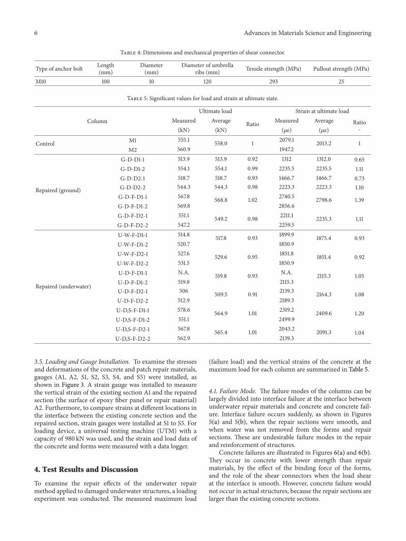
Table 5: Significant values for load and strain at ultimate state.
Ultimate load Strain at ultimate loadColumn Measured Average Ratio Measured Average
(kN) (kN) (𝜇𝜀) (𝜇𝜀)Ratio-
Control M1 555.1 558.0 1 2079.1 2013.2M2 560.9 1947.2
1
G-D-D1-1 513.9 513.9 0.92 1312 1312.0 0.65G-D-D1-2 554.1 554.1 0.99 2235.5 2235.5 1.11
Repaired (ground)
G-D-D2-1 518.7 518.7 0.93 1466.7 1466.7 0.73G-D-D2-2 544.3 544.3 0.98 2223.3 2223.3 1.10G-D-F-D1-1 567.8 568.8 1.02 2740.5 2798.6G-D-F-D1-2 569.8 2856.6
1.39
G-D-F-D2-1 551.1 549.2 0.98 2211.1 2235.3G-D-F-D2-2 547.2 2259.5
1.11
U-W-F-D1-1 514.8 517.8 0.93 1899.9 1875.4U-W-F-D1-2 520.7 1850.9
0.93
U-W-F-D2-1 527.6 529.6 0.95 1851.8 1851.4U-W-F-D2-2 531.5 1850.9
0.92
U-D-F-D1-1 N.A. 519.8 0.93 N.A. 2115.3
Repaired (underwater) U-D-F-D1-2 519.8 2115.31.05
U-D-F-D2-1 506 509.5 0.91 2139.3 2164.3U-D-F-D2-2 512.9 2189.3
1.08
U-D,S-F-D1-1 578.6 564.9 1.01 2319.2 2409.6U-D,S-F-D1-2 551.1 2499.9
1.20
U-D,S-F-D2-1 567.8 565.4 1.01 2043.2 2091.3U-D,S-F-D2-2 562.9 2139.3
1.04
3.5. Loading and Gauge Installation. To examine the stressesand deformations of the concrete and patch repair materials,gauges (A1, A2, S1, S2, S3, S4, and S5) were installed, asshown in Figure 3. A strain gauge was installed to measurethe vertical strain of the existing section A1 and the repairedsection (the surface of epoxy fiber panel or repair material)A2. Furthermore, to compare strains at different locations inthe interface between the existing concrete section and therepaired section, strain gauges were installed at S1 to S5. Forloading device, a universal testing machine (UTM) with acapacity of 980 kN was used, and the strain and load data ofthe concrete and forms were measured with a data logger.
4. Test Results and Discussion
To examine the repair effects of the underwater repairmethod applied to damaged underwater structures, a loadingexperiment was conducted. The measured maximum load
(failure load) and the vertical strains of the concrete at themaximum load for each column are summarized in Table 5.
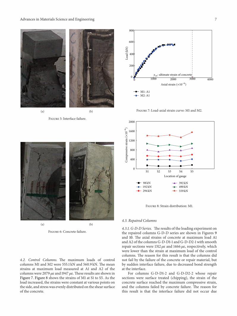
4.1. Failure Mode. The failure modes of the columns can belargely divided into interface failure at the interface betweenunderwater repair materials and concrete and concrete fail-ure. Interface failure occurs suddenly, as shown in Figures5(a) and 5(b), when the repair sections were smooth, andwhen water was not removed from the forms and repairsections. These are undesirable failure modes in the repairand reinforcement of structures.
Concrete failures are illustrated in Figures 6(a) and 6(b).They occur in concrete with lower strength than repairmaterials, by the effect of the binding force of the forms,and the role of the shear connectors when the load shearat the interface is smooth. However, concrete failure wouldnot occur in actual structures, because the repair sections arelarger than the existing concrete sections.
Advances in Materials Science and Engineering 7
(a) (b)
Figure 5: Interface failure.
(a) (b)
Figure 6: Concrete failure.
4.2. Control Columns. The maximum loads of controlcolumns M1 and M2 were 555.1 kN and 560.9 kN. The meanstrains at maximum load measured at A1 and A2 of thecolumns were 2079𝜇𝜀 and 1947 𝜇𝜀.These results are shown inFigure 7. Figure 8 shows the strains of M1 at S1 to S5. As theload increased, the strains were constant at various points onthe side, and stress was evenly distributed on the shear surfaceof the concrete.
1000 2000 3000 40000
0
200
400
600
800
M1: A1
Load
(kN
)
Axial strain (×10−6)
M2: A1
𝜀𝑐𝑢 : ultimate strain of concrete
Figure 7: Load-axial strain curve: M1 and M2.
Location of gaugeS1 S2 S3 S4 S5
0
400
800
1200
1600
2000
98kN192kN294kN
392kN490kN559kN
Com
pres
sive s
trai
n (×10−6)
Figure 8: Strain distribution: M1.
4.3. Repaired Columns
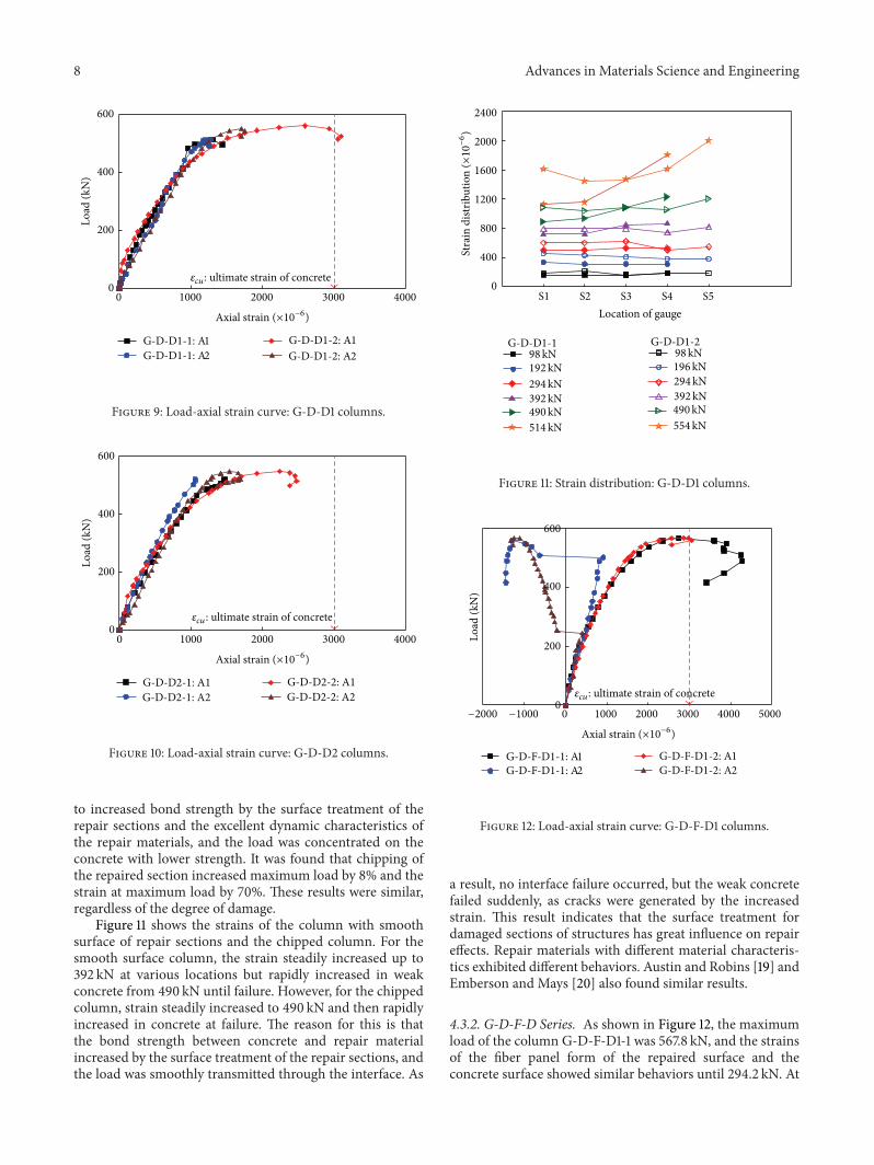
4.3.1. G-D-D Series. The results of the loading experiment onthe repaired columns G-D-D series are shown in Figures 9and 10. The axial strains of concrete at maximum load A1and A2 of the columns G-D-D1-1 and G-D-D2-1 with smoothrepair sections were 1312 𝜇𝜀 and 1466 𝜇𝜀, respectively, whichwere lower than the strain at maximum load of the controlcolumns. The reason for this result is that the columns didnot fail by the failure of the concrete or repair material, butby sudden interface failure, due to decreased bond strengthat the interface.
For columns G-D-D1-2 and G-D-D2-2 whose repairsections were surface treated (chipping), the strain of theconcrete surface reached the maximum compressive strain,and the columns failed by concrete failure. The reason forthis result is that the interface failure did not occur due
8 Advances in Materials Science and EngineeringLo
ad (k
N) 400
600
200
00 1000 2000 3000 4000
G-D-D1-1: A1G-D-D1-1: A2 G-D-D1-2: A2
G-D-D1-2: A1
Axial strain (×10−6)
𝜀𝑐𝑢 : ultimate strain of concrete
Figure 9: Load-axial strain curve: G-D-D1 columns.
Load
(kN
) 400
600
200
0
0 1000 2000 3000 4000
Axial strain (×10−6)
G-D-D2-1: A1G-D-D2-1: A2
G-D-D2-2: A1G-D-D2-2: A2
𝜀𝑐𝑢 : ultimate strain of concrete
Figure 10: Load-axial strain curve: G-D-D2 columns.
to increased bond strength by the surface treatment of therepair sections and the excellent dynamic characteristics ofthe repair materials, and the load was concentrated on theconcrete with lower strength. It was found that chipping ofthe repaired section increased maximum load by 8% and thestrain at maximum load by 70%. These results were similar,regardless of the degree of damage.
Figure 11 shows the strains of the column with smoothsurface of repair sections and the chipped column. For thesmooth surface column, the strain steadily increased up to392 kN at various locations but rapidly increased in weakconcrete from 490 kN until failure. However, for the chippedcolumn, strain steadily increased to 490 kN and then rapidlyincreased in concrete at failure. The reason for this is thatthe bond strength between concrete and repair materialincreased by the surface treatment of the repair sections, andthe load was smoothly transmitted through the interface. As
Stra
in d
istrib
utio
n (×10−6)
Location of gauge
0
400
800
1200
1600
2000
2400
S1 S2 S3 S4 S5
G-D-D1-1 G-D-D1-298kN192kN294kN392kN490kN514kN
98kN196kN294kN392kN490kN554kN
Figure 11: Strain distribution: G-D-D1 columns.Lo
ad (k
N) 400
600
200
00−1000−2000 3000 40001000 2000 5000
Axial strain (×10−6)
G-D-F-D1-1: A1G-D-F-D1-1: A2
G-D-F-D1-2: A1G-D-F-D1-2: A2
𝜀𝑐𝑢 : ultimate strain of concrete
Figure 12: Load-axial strain curve: G-D-F-D1 columns.
a result, no interface failure occurred, but the weak concretefailed suddenly, as cracks were generated by the increasedstrain. This result indicates that the surface treatment fordamaged sections of structures has great influence on repaireffects. Repair materials with different material characteris-tics exhibited different behaviors. Austin and Robins [19] andEmberson and Mays [20] also found similar results.
4.3.2. G-D-F-D Series. As shown in Figure 12, the maximumload of the column G-D-F-D1-1 was 567.8 kN, and the strainsof the fiber panel form of the repaired surface and theconcrete surface showed similar behaviors until 294.2 kN. At
Advances in Materials Science and Engineering 9
Load
(kN
) 400
600
200
0
0−1000−2000 3000 40001000 2000
Axial strain (×10−6)
G-D-F-D2-1: A1G-D-F-D2-1: A2
G-D-F-D2-2: A1G-D-F-D2-2: A2
𝜀𝑐𝑢 : ultimate strain of concrete
Figure 13: Load-axial strain curve: G-D-F-D2 columns.
400
800
1200
1600
0
Stra
in d
istrib
utio
n (×10−6)
Location of gaugeS1 S2 S3 S4 S5
98kN192kN294kN392kN490kN568kN
98kN196kN294kN392kN490kN569kN
G-D-F-D1-1 G-D-F-D1-2
Figure 14: Strain distribution: G-D-F-D1 columns.
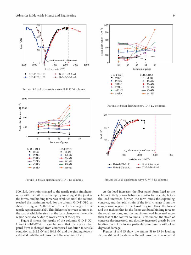
500.1 kN, the strain changed to the tensile region simultane-ously with the failure of the epoxy finishing at the joint ofthe forms, and binding force was exhibited until the columnreached the maximum load. For the column G-D-F-D1-2, asshown in Figure 12, the strain of the form changes to thetensile region at 245.2 kN.This difference between columns inthe load at which the strain of the form changes to the tensileregion seems to be due to work errors of the epoxy.
Figure 13 shows the results of the columns G-D-F-D2-1 and G-D-F-D2-2. It can be seen that the epoxy fiberpanel form is changed from compressed condition to tensilecondition at 242.2 kN and 196.1 kN, and the binding force isexhibited until the columns reach the maximum load.
Stra
in d
istrib
utio
n (×10−6)
Location of gauge
1000
800
600
200
0
S1 S2 S3 S4 S5
98kN192kN294kN392kN490kN552kN
98kN196kN294kN392kN490kN547kN
400
G-D-F-D2-1 G-D-F-D2-2
Figure 15: Strain distribution: G-D-F-D2 columns.
1000 20000 3000 4000
Axial strain (×10−6)
0
Load
(kN
)
200
400
600
U-W-F-D1-1: A1U-W-F-D1-1: A2
U-W-F-D1-2: A1U-W-F-D1-2: A2
𝜀𝑐𝑢 : ultimate strain of concrete
Figure 16: Load-axial strain curve: U-W-F-D1 columns.
As the load increases, the fiber panel form fixed to thecolumn initially shows behaviors similar to concrete, but asthe load increased further, the form binds the expandingconcrete, and the axial strain of the form changes from thecompressive region to the tensile region. Thus, the formsand the anchors that fix the forms exhibited binding force tothe repair sections, and the maximum load increased morethan that of the control columns. Furthermore, the strain ofconcrete also increased, and ductility increased greatly by thebinding force of the forms, particularly in columns with a lowdegree of damage.
Figures 14 and 15 show the strains S1 to S5 by loadingsteps at different locations of the columns that were repaired

10 Advances in Materials Science and Engineering
1000 2000
0
3000 4000
Axial strain (×10−6)
0
Load
(kN
)
200
400
600
U-W-F-D2-1: A1U-W-F-D2-1: A2
U-W-F-D2-2: A1U-W-F-D2-2: A2
𝜀𝑐𝑢 : ultimate strain of concrete
Figure 17: Load-axial strain curve: U-W-F-D2 columns.
0
200
400
600
800
1000
1200
Location of gauge
Stra
in d
istrib
utio
n (×10−6)
S1 S2 S3 S4 S5
98kN192kN294kN392kN490kN515kN
98kN196kN294kN392kN490kN521kN
U-W-F-D1-1 U-W-F-D1-2
Figure 18: Strain distribution: U-W-F-D1 columns.
using fiber panel forms on the ground. No interface failureoccurred due to the increased bond strength at the interfaceby chipping and the binding force of the fiber panel formsand anchor bolts. However, when the load increased over490.3 kN, the strain of concrete rapidly increased, and failureoccurred at the load of 539.4 kN or higher. The reason forthis result seems to be that the bond strength at the interfaceincreased by chipping, and the binding force of the forms andanchors inhibited expansion and failure, thus improving therepair effects.
4.3.3. U-W-F-D Series. The loading experiment results for thecolumns U-W-F-D series are shown in Figures 16 and 17. The
0
200
400
600
1000 2000 3000 4000 5000
Axial strain (×10−6)
Load
(kN
)
U-D-F-D1-2: A1U-D-F-D1-2: A2
0
𝜀𝑐𝑢 : ultimate strain of concrete
Figure 19: Load-axial strain curve: U-D-F-D1-2 column.
600
400
200
0
0 1000 2000 3000 4000 5000
Load
(kN
)
Axial strain (×10−6)
U-D-F-D2-2: A1U-D-F-D2-2: A2
U-D-F-D2-1: A1U-D-F-D2-1: A2
𝜀𝑐𝑢 : ultimate strain of concrete
Figure 20: Load-axial strain curve: U-D-F-D2 columns.
columns failed at themaximum load of 509.9 to 529.6 kN, andthe axial strain A1 at maximum load was 1850 𝜇𝜀 to 1899𝜇𝜀,smaller than that of the control column.
Unlike the results for the columns produced on theground (G-D-F-D series), the strain of the epoxy fiber panelforms of the columns produced under water wasmeasured incompressed condition until failure.
These results seem to have been caused by the specialunderwater working condition. In other words, for the formsto exhibit definite binding forces, the repair materials andthe existing concrete sections must be completely bonded,and the load must be transmitted smoothly. However, dueto the underwater working condition, the water in the formsreduced the bonding force between the repair materials andthe repair sections, and interface failure developed before theforms exhibited binding force.

Advances in Materials Science and Engineering 11
98kN192kN294kN
392kN490kN511kN
U-D-F-D1-1
2000
1600
1200
800
400
0
S1 S2 S3 S4 S5
Stra
in d
istrib
utio
n (×10−6)
Location of gauge
Figure 21: Strain distribution: U-D-F-D1-1 column.
600
400
200
0
0 1000 2000 3000 4000 5000
Axial strain (×10−6)
Load
(kN
)
𝜀𝑐𝑢 : ultimate strain of concrete
U-D,S-F-D1-2: A1U-D,S-F-D1-2: A2
U-D,S-F-D1-1: A1U-D,S-F-D1-1: A2
Figure 22: Load-axial strain curve: U-D,S-F-D1 columns.
Therefore, to improve the repair effects of underwaterstructures using forms, the water between repair sections andforms must be removed, so as to inhibit the washing andleaking of the patch repair materials.
Figure 18 shows the distribution of strains at differentlocations on the sides of the concrete and repair materials, forthe columns U-W-F-D1. The changes of strains by increasingload at different locations were not clear, and the concrete andrepair materials did not fail, either. The reason for this seemsto be the occurrence of interface failure, which prevented thetransmission of load to the repair sections, thus decreasingmaximum load and strain.
4.3.4. U-D-F-D Series. The loading experiment results for thecolumns U-D-F-D series are shown in Figures 19 and 20.The maximum load of the repaired columns U-D-F-D series
1000 20000 3000 4000
Axial strain (×10−6)
0
Load
(kN
)
200
400
600
5000
𝜀𝑐𝑢 : ultimate strain of concrete
U-D,S-F-D2-2: A1U-D,S-F-D2-2: A2
U-D,S-F-D2-1: A1U-D,S-F-D2-1: A2
Figure 23: Load-axial strain curve: U-D,S-F-D2 columns.
Stra
in d
istrib
utio
n (×10−6)
Location of gauge
0
400
800
1200
1600
S1 S2 S3 S4 S5
98kN192kN294kN
392kN490kN551kN
U-D,S-F-D1-2
Figure 24: Strain distribution: U-D,S-F-D1-2 column.
ranged from 500.1 to 519.8 kN, which was lower by 7–9% thanthat of the control column. However, the strain of concretewas 2100 𝜇𝜀 or higher, by the binding force between formsand anchors.
Columns U-D-F-D series, which were repaired by under-water work, showed lower maximum loads, compared to therepaired columns produced by ground repair work. However,interface failure, which is important in repair works, did nothappen. The reason for this seems to be that the proposedunderwater repair method inhibited the interface failurebetween underwater repair materials and concrete, by thewater removal process before injection of the underwaterrepair materials, and the water tightness provided by theepoxy fiber panel forms.
12 Advances in Materials Science and EngineeringSt
rain
dist
ribut
ion
(×10−6)
Location of gauge
0
400
800
1200
1600
S1 S2 S3 S4 S5
98kN192kN294kN392kN490kN567kN
98kN196kN294kN392kN490kN562kN
U-D,S-F-D2-1 U-D,S-F-D2-2
Figure 25: Strain distribution: U-D,S-F-D2 columns.
Figure 21 shows the strains at different locations on thesides of the underwater repair materials and concrete for thecolumn U-D-F-D1-1. Concrete failure occurred at 509.9 kN,as strain on the concrete suddenly increased. In other words,the strains of concrete sections and repaired sections alsosteadily changed until failure. The reason for this seems tobe that the water tightness by forms increased the bondforce of the repaired sections and facilitated the smoothtransmission of load. Removing the water from the forms andrepair sections before injecting underwater repair materialsinhibited the leaking andwashing of the repairmaterials, thusincreasing the bond force at the interface. Furthermore, thewater tightness and binding force by forms were effective inunderwater working conditions and increased the bondingforce of the repair materials and concrete sections at theinterface, thus improving repair effects.
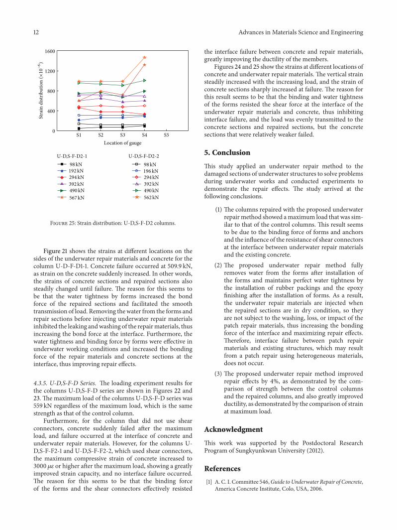
4.3.5. U-D,S-F-D Series. The loading experiment results forthe columns U-D,S-F-D series are shown in Figures 22 and23. The maximum load of the columns U-D,S-F-D series was559 kN regardless of the maximum load, which is the samestrength as that of the control column.
Furthermore, for the column that did not use shearconnectors, concrete suddenly failed after the maximumload, and failure occurred at the interface of concrete andunderwater repair materials. However, for the columns U-D,S-F-F2-1 and U-D,S-F-F2-2, which used shear connectors,the maximum compressive strain of concrete increased to3000 𝜇𝜀 or higher after the maximum load, showing a greatlyimproved strain capacity, and no interface failure occurred.The reason for this seems to be that the binding forceof the forms and the shear connectors effectively resisted
the interface failure between concrete and repair materials,greatly improving the ductility of the members.
Figures 24 and 25 show the strains at different locations ofconcrete and underwater repair materials. The vertical strainsteadily increased with the increasing load, and the strain ofconcrete sections sharply increased at failure. The reason forthis result seems to be that the binding and water tightnessof the forms resisted the shear force at the interface of theunderwater repair materials and concrete, thus inhibitinginterface failure, and the load was evenly transmitted to theconcrete sections and repaired sections, but the concretesections that were relatively weaker failed.
5. Conclusion
This study applied an underwater repair method to thedamaged sections of underwater structures to solve problemsduring underwater works and conducted experiments todemonstrate the repair effects. The study arrived at thefollowing conclusions.
(1) The columns repaired with the proposed underwaterrepairmethod showed amaximum load that was sim-ilar to that of the control columns. This result seemsto be due to the binding force of forms and anchorsand the influence of the resistance of shear connectorsat the interface between underwater repair materialsand the existing concrete.
(2) The proposed underwater repair method fullyremoves water from the forms after installation ofthe forms and maintains perfect water tightness bythe installation of rubber packings and the epoxyfinishing after the installation of forms. As a result,the underwater repair materials are injected whenthe repaired sections are in dry condition, so theyare not subject to the washing, loss, or impact of thepatch repair materials, thus increasing the bondingforce of the interface and maximizing repair effects.Therefore, interface failure between patch repairmaterials and existing structures, which may resultfrom a patch repair using heterogeneous materials,does not occur.
(3) The proposed underwater repair method improvedrepair effects by 4%, as demonstrated by the com-parison of strength between the control columnsand the repaired columns, and also greatly improvedductility, as demonstrated by the comparison of strainat maximum load.
Acknowledgment
This work was supported by the Postdoctoral ResearchProgram of Sungkyunkwan University (2012).
References
[1] A. C. I. Committee 546,Guide toUnderwater Repair of Concrete,America Concrete Institute, Colo, USA, 2006.
Advances in Materials Science and Engineering 13
[2] I. Lasa, R. Powers, and R. Kessler, “Practical application ofcathodic protection systems for reinforcing steel substructuresin marine environment,” in Proceedings of the InternationalSeminar on Repair and Rehabilitation of Reinforced ConcreteStructures, pp. 16–31, Maracaibo, Venezuela, May 1997.
[3] K. Han, S. Hong, and S. Park, “Seismic performance evaluationof retrofitted bridge by isolation bearings,”Baltic Journal of Roadand Bridge Engineering, vol. 4, no. 3, pp. 134–142, 2009.
[4] D. Y. Cho, S. K. Park, and S. N. Hong, “Bond-slip behavior ofcfrp plate-concrete interface,” Mechanics of Composite Materi-als, vol. 47, no. 5, pp. 529–538, 2011.
[5] K. B. Han, S. Hong, and S. K. Park, “RC slabs repairedand strengthened by alumina/polymer mortar and prestressingstrands in the tension zone: experimental investigation understatic and fatigue loadings,” Mechanics of Composite Materials,vol. 48, no. 5, pp. 587–602, 2012.
[6] S. Hong and S. K. Park, “Effect of prestress levels on flexural anddebonding behavior of reinforced concrete beams strengthenedwith prestressed carbon fiber reinforced polymer plates,” Jour-nal of Composite Materials, 2012.
[7] D. Cambel-Allen and H. Roper, Concrete Structures: Material,Maintenance and Repair, Concrete Design and ConstructionSeries, Longman, Singapore, 1991.
[8] J. L. Ramı́rez, “Ten concrete column repair methods,”Construc-tion and Building Materials, vol. 10, no. 3, pp. 195–202, 1996.
[9] Departments of the Army and Air Force (Headquarters),“Repair of rigid pavements using epoxy-resin grouts, mortars,and concrete (ch 10),” TM 5-822-9/AFM88-6,Washington, DC,USA, 1989.
[10] G.W.Depuy, “Polymermodified concrete-properties and appli-cations,” Construction Repair, vol. 10, no. 2, pp. 63–67, 1996.
[11] Y.Ohama,Handbook of Polymer-ModifiedConcrete andMortarsProperties and Process Technology, Noyes Publications, ParkRidge, NJ, USA, 1995.
[12] UEG, “The influence ofmethods andmaterials on the durabilityof repairs to concrete coastal and offshore structures,” UEGPublication UR 36(CIRIA/UEG), London, UK, 1986.
[13] B. Herroelen, D. Van Gemert, and K. Brosen, “Repair andstrengthening of a swimming pool roof structure using polymerconcrete and CFRP laminates,” in Proceedings of the 9th ICPIC,pp. 419–425, Bologna, Italy, 1998.
[14] V. A. Lissenko, “Durability and structure formation of polymercomposites for restoration and conservation of ancient archi-tectural heritage,” in Proceedings of the 9 ICPIC, pp. 699–708,Bologna, Italy, 1998.
[15] K. S. Rebeiz, D. W. Fowler, and D. R. Paul, “Recycling plasticsin polymer concrete for construction applications,” Journal ofMaterials in Civil Engineering, vol. 5, no. 2, pp. 237–248, 1993.
[16] G. Mullins, R. Sen, K. Suh, and D. Winters, “Underwater fiber-reinforced polymers repair of prestressed piles in the AllenCreek Bridge,” Journal of Composites for Construction, vol. 9, no.2, pp. 136–146, 2005.
[17] J. Y. Yeom, Underwater Concrete Repairing, Lotte Engineeringand Construction, Seoul, South Korea, 2005.
[18] S. Bazinet, L. Cereone, and F. Worth, “Composite FRP movesinto underwater repair applications,” SAMPE Journal, vol. 39,no. 3, pp. 8–16, 2003.
[19] S. A. Austin and P. J. Robins, “Development of patch test tostudy behavior of shallow concrete patch repairs,” Magazine ofConcrete Research, vol. 45, no. 164, pp. 221–229, 1993.
[20] N. K. Emberson and G. C. Mays, “Significance of propertymismatch in the patch repair of structural concrete—part2: axially loaded reinforced concrete members,” Magazine ofConcrete Research, vol. 48, no. 1, pp. 45–57, 1996.

Submit your manuscripts athttp://www.hindawi.com
ScientificaHindawi Publishing Corporationhttp://www.hindawi.com Volume 2014
CorrosionInternational Journal of
Hindawi Publishing Corporationhttp://www.hindawi.com Volume 2014
Polymer ScienceInternational Journal of
Hindawi Publishing Corporationhttp://www.hindawi.com Volume 2014
Hindawi Publishing Corporationhttp://www.hindawi.com Volume 2014
CeramicsJournal of
Hindawi Publishing Corporationhttp://www.hindawi.com Volume 2014
CompositesJournal of
NanoparticlesJournal of
Hindawi Publishing Corporationhttp://www.hindawi.com Volume 2014
Hindawi Publishing Corporationhttp://www.hindawi.com Volume 2014
International Journal of
Biomaterials
Hindawi Publishing Corporationhttp://www.hindawi.com Volume 2014
NanoscienceJournal of
TextilesHindawi Publishing Corporation http://www.hindawi.com Volume 2014
Journal of
NanotechnologyHindawi Publishing Corporationhttp://www.hindawi.com Volume 2014
Journal of
CrystallographyJournal of
Hindawi Publishing Corporationhttp://www.hindawi.com Volume 2014
The Scientific World JournalHindawi Publishing Corporation http://www.hindawi.com Volume 2014
Hindawi Publishing Corporationhttp://www.hindawi.com Volume 2014
CoatingsJournal of
Advances in
Materials Science and EngineeringHindawi Publishing Corporationhttp://www.hindawi.com Volume 2014
Smart Materials Research
Hindawi Publishing Corporationhttp://www.hindawi.com Volume 2014
Hindawi Publishing Corporationhttp://www.hindawi.com Volume 2014
MetallurgyJournal of
Hindawi Publishing Corporationhttp://www.hindawi.com Volume 2014
BioMed Research International
MaterialsJournal of
Hindawi Publishing Corporationhttp://www.hindawi.com Volume 2014
Nano
materials
Hindawi Publishing Corporationhttp://www.hindawi.com Volume 2014
Journal ofNanomaterials
Related Documents