Research Article Analytical and Numerical Investigation of Lacing Wire Damage Induced Mistuning in Turbine Blade Packet Mangesh S. Kotambkar and Animesh Chatterjee Department of Mechanical Engineering, Visvesvaraya National Institute of Technology, Nagpur 440010, India Correspondence should be addressed to Mangesh S. Kotambkar; [email protected] Received 15 August 2014; Accepted 12 November 2014; Published 9 December 2014 Academic Editor: Abdelkrim Khelif Copyright © 2014 M. S. Kotambkar and A. Chatterjee. is is an open access article distributed under the Creative Commons Attribution License, which permits unrestricted use, distribution, and reproduction in any medium, provided the original work is properly cited. Investigations of modal parameters for a mistuned packet of turbine blades due to lacing wire damage are reported using analytical and numerical studies with a simplified model. e turbine blade is assumed to be an Euler-Bernoulli beam connected with a lacing wire which is modeled as a mass less linear elastic spring. us, the blade is considered as a continuous system and lacing wire as a discrete system. e analytical results using Eigen value analysis are compared with numerical results obtained using commercial finite element package. In real life situation, though not reported in the literature, it is the failure of lacing wire that occurs quite oſten compared to the turbine blade and acts as precursor to the subsequent blade damage if it goes undetected. erefore, studying the modal parameters of the grouped turbine blades in the context of lacing wire failure becomes important. e effect of variation of lacing wire location and stiffness indicative of damage resulting in the loss of stiffness on modal parameters is investigated. e study reveals a lot of fundamental understandings pertaining to dynamic behavior of grouped blades compared to the stand-alone blade under the influence of damaged lacing wire. 1. Introduction Turbine is the most widely used prime movers in power plants, turbo engines, and compressors in aircraſts and also in auxiliary turbo driven equipment such as turbo pumps. Tur- bine blade vibration and its failure under high cycle fatigue is an important area of research studies due to its critical applications. e blade failures are mainly due to resonant stresses when one of the natural frequencies of blade-disk system matches the nozzle passing frequency. Design of these turbomachine blades thus critically depends on accurate understanding of the blade vibration characteristics under varied operating conditions. However, modeling and analysis of turbine blade vibration becomes quite complex due to continuously tapered and twisted cross-section and blade to blade dynamic coupling through lacing wire or shroud rings. Almost 50% of low pressure steam turbine blade failure is due to fatigue caused by vibration [1]. A turbine blade is a complex geometry having aerofoil shape with varying width and thickness along its length. Most of the early research works have been based on simplified cantilever beam modeling where effects of root flexibility and crack in the stand-alone blade have been studied [2–9]. However, the dynamics of grouped blades is even more complex than a free stand-alone blade. Rao [10] has summarized the vibration behavior of turbine blades studied numerically and experimentally in the past in his book. In the recent past, research on turbine blade has focused on blades in a packet. ere are many advantages of packeted turbine blades connected with lacing wire. For instance, resultant natural frequency increases with the number of blades in group and stiffening due to interconnection of blades with the lacing wire. Smith [11] has made significant contribution in deter- mining the group frequencies and mode shapes of a blade packet. He also discussed the use of lacing wire in turbine blade groups. Ellington and McCallion [12] simplified Smith’s analysis by using finite difference calculus to the special case of blade group with a tie wire which joins the blade tips together. Prohl [13] used lumped parameter approach by consider- ing series of concentrated masses and concentrated stiffness Hindawi Publishing Corporation Advances in Acoustics and Vibration Volume 2014, Article ID 164638, 16 pages http://dx.doi.org/10.1155/2014/164638

Welcome message from author
This document is posted to help you gain knowledge. Please leave a comment to let me know what you think about it! Share it to your friends and learn new things together.
Transcript
Research ArticleAnalytical and Numerical Investigation of Lacing Wire DamageInduced Mistuning in Turbine Blade Packet
Mangesh S Kotambkar and Animesh Chatterjee
Department of Mechanical Engineering Visvesvaraya National Institute of Technology Nagpur 440010 India
Correspondence should be addressed to Mangesh S Kotambkar mskotambyahoocom
Received 15 August 2014 Accepted 12 November 2014 Published 9 December 2014
Academic Editor Abdelkrim Khelif
Copyright copy 2014 M S Kotambkar and A Chatterjee This is an open access article distributed under the Creative CommonsAttribution License which permits unrestricted use distribution and reproduction in any medium provided the original work isproperly cited
Investigations of modal parameters for a mistuned packet of turbine blades due to lacing wire damage are reported using analyticaland numerical studies with a simplifiedmodelThe turbine blade is assumed to be an Euler-Bernoulli beam connected with a lacingwire which is modeled as a mass less linear elastic spring Thus the blade is considered as a continuous system and lacing wire as adiscrete system The analytical results using Eigen value analysis are compared with numerical results obtained using commercialfinite element package In real life situation though not reported in the literature it is the failure of lacing wire that occurs quiteoften compared to the turbine blade and acts as precursor to the subsequent blade damage if it goes undetectedTherefore studyingthe modal parameters of the grouped turbine blades in the context of lacing wire failure becomes important The effect of variationof lacing wire location and stiffness indicative of damage resulting in the loss of stiffness on modal parameters is investigated Thestudy reveals a lot of fundamental understandings pertaining to dynamic behavior of grouped blades compared to the stand-aloneblade under the influence of damaged lacing wire
1 Introduction
Turbine is the most widely used prime movers in powerplants turbo engines and compressors in aircrafts and also inauxiliary turbo driven equipment such as turbo pumps Tur-bine blade vibration and its failure under high cycle fatigueis an important area of research studies due to its criticalapplications The blade failures are mainly due to resonantstresses when one of the natural frequencies of blade-disksystemmatches the nozzle passing frequency Design of theseturbomachine blades thus critically depends on accurateunderstanding of the blade vibration characteristics undervaried operating conditions However modeling and analysisof turbine blade vibration becomes quite complex due tocontinuously tapered and twisted cross-section and blade toblade dynamic coupling through lacing wire or shroud rings
Almost 50 of low pressure steam turbine blade failureis due to fatigue caused by vibration [1] A turbine bladeis a complex geometry having aerofoil shape with varyingwidth and thickness along its length Most of the earlyresearchworks have been based on simplified cantilever beam
modeling where effects of root flexibility and crack in thestand-alone blade have been studied [2ndash9] However thedynamics of grouped blades is evenmore complex than a freestand-alone blade
Rao [10] has summarized the vibration behavior ofturbine blades studied numerically and experimentally inthe past in his book In the recent past research on turbineblade has focused on blades in a packet There are manyadvantages of packeted turbine blades connected with lacingwire For instance resultant natural frequency increaseswith the number of blades in group and stiffening due tointerconnection of blades with the lacing wire
Smith [11] has made significant contribution in deter-mining the group frequencies and mode shapes of a bladepacket He also discussed the use of lacing wire in turbineblade groups Ellington andMcCallion [12] simplified Smithrsquosanalysis by using finite difference calculus to the special caseof blade group with a tie wire which joins the blade tipstogether
Prohl [13] used lumped parameter approach by consider-ing series of concentrated masses and concentrated stiffness
Hindawi Publishing CorporationAdvances in Acoustics and VibrationVolume 2014 Article ID 164638 16 pageshttpdxdoiorg1011552014164638
2 Advances in Acoustics and Vibration
to model the blade group A modified Holzer technique wasused to calculate the natural frequencies and mode shapesRao [14] employed energy approach using Hamiltonrsquos prin-ciple to derive the equations of motion and the boundaryconditions
Bajaj [15] has used the finite element method to deter-mine the natural frequencies of packeted blades in coupledbending-bending-torsion modes Thomas and Belek [16]have also used finite element model for a group of bladeswith rectangular cross-section to find modal parametersin the tangential mode Salama and Petyt [17] have usedfinite element model and periodical structural analysis of thetangential vibration of packeted blades both the positions ofthe lacing wire and rotations were taken into account
Lim and Yoo [18] have studied modal analysis of multi-blade system undergoing rotational motion It is reportedthat the increase in rotational speed increases stiffness ofthe system there by increasing the natural frequencies Theyhave also reported that increase in coupling stiffness increasesthe gap between the frequency loci Lim et al [19] have alsoreported the frequency split due to N number of blades inan Np number of packets as NNp + 1 They have consideredtapered cantilever beam and used finite element approach formodal analysis
These research works mainly focused on tuned bladepacket inwhich all the blades are considered to be identical toeach otherHowevermistuningmay exist in the formof bladeto blade variation in structural and geometrical propertiesdue to manufacturing tolerances operational wear and tearor incipient crack growth Effect of mistuning in a bladegroup was first investigated by Ewins [20] Wei and Pierre[21] studied mistuning caused by geometric variations andreported that even a small mistuning in such cases can lead tovibration localization and amplification of stress amplitudesin the blades Castanier and Pierre [22] have presented areview on reduced-order modeling simulation and analysisof the vibration of bladed disks found in gas-turbine enginesin which applications to system identification and design arealso considered An emphasis is placed on key developmentsthat have enabled better prediction and understanding of theforced response of mistuned bladed disks especially withrespect to assessing and mitigating the harmful impact ofmistuning on blade vibration stress increases and attendanthigh cycle fatigue
Hou [23]workedwith lumped parametermodel inwhichthe local degradation in stiffness due to blade crack isexpressed with a flexibility matrix Effect of near root bladecrack on stability of a packeted blade has been investigated byHuang andKuang [24] Fang et al [25] analysed themistunedsystem as cantilever beams interconnected with springs andused fracture mechanics to determine crack induced stiffnessloss in a beam (Figure 4) It is reported that crack in the blademay not cause a significant frequency change but it may leadto forced vibration localization in a periodic structure underloss of cyclic symmetry Saito et al [26] considered crack asa nonlinear stiffness and used reduced order modeling forstudying the effect of blade damage on vibration responsecharacteristics
In all these research works mistuning has been limited toblade damage only However practical experience shows thatlacingwire damage or breakages aremore frequent than bladedamage during the operational period of the turbine as theycome directly in the path of steam flowgas flowThe damagemay be initially a small surface crack and if left unattended orundetected such damages finally induce stress localization inthe blades leading to blade failure Unfortunately not muchresearch work has been reported in this area particularlyfor blade packets with lacing wire damage The present workfocuses on investigating the effect of lacing wire damage onloss of cyclic symmetry in a blade packet and subsequentcharacteristic changes in the modal properties Both lacingwire at the blade tip and lacing wire at an intermediateposition are considered Effect of relative stiffness of the lacingwire to blade stiffness on the modal spectrum for a tunedand mistuned blade packet is investigated Further studieshave been carried out to characterize modal properties forvarying damage severity and damage at different locations inthe lacing wire loop
2 Modeling and Analysis ofTuned Blade Packet
The turbine blades and disk system is cyclic structure con-sisting of a number of blade packets Each packet has mul-tiple blades interconnected with lacing wire or shroud ringLow pressure turbine stages have long slender blades whichundergo high bending deformation caused by natural fre-quencies in the lower operating range These blades gothrough transient resonant condition at nozzle passing fre-quency [10] In order to limit the vibratory deformationsthese blades of low pressure stages are often stiffened withlacing wire connections These lacing wires are actually rodsof circular cross-sections and are connected with the bladesusing brazing material A typical turbine blade disk systemwith lacing wire interconnection is shown in Figure 1 It canbe seen that the blades are arranged in groups called bladepackets Each blade packet consists of a small number ofinterconnected blades (generally five to seven bladse for lowpressure turbine stages)
The packeted blade disk configuration can be consideredas a domain composed of identical subdomains that havesymmetry with respect to an axis Analysis of only one ofthe subdomains represents the key in obtainingmajor savingsin computation time The subdomain or sector builds up thewhole domain by rotating the subdomain by 2120587119869 where 119869is the number of identical sectors Thus dynamic modelingand analysis is done for one blade packet (Figure 2) only withappropriate boundary conditions and this saves considerableamount of computational work and time
In the present study it is assumed that failure of the lacingwire would occur gradually through crack growth resultingin a reduction in its stiffness Stiffness value of the lacing wireis varied as a ratio to the blade stiffness The objective in thepresent work ismainly to find answers to following questions
Advances in Acoustics and Vibration 3
Lacing wire
Blade
Disk
Figure 1 Turbine blade disk model with lacing wire
Figure 2 One packet of turbine blades with lacing wire
(i) In what way dynamic behavior and modal charac-teristics of free standing blade configuration to inter-connected blade packet configuration differ and howdo these modal characteristics depend on the relativestiffness and location of the lacing wire number ofblades interconnected in a packet and so forth
(ii) What would be the qualitative and quantitative shiftin themodal properties of the affected blade packet incase of a partial damagecrack or complete breakagein a lacing wire
(iii) In what way the changes in the modal properties canbe used to identify the severity and location of thelacing wire damage
A mathematical formulation is presented here for a typicalthree bladed packets with lacing wire positioned at the bladetip initially and subsequently similar analysis for lacing wireat an intermediate position is presented in later sectionsLacing wires are modeled as a spring laterally connectedto the blades and governing differential equations of freevibration are derived using Euler-Bernoulli beam theoryThespring force coming from the lacing wire modifies the shearforce (SF) boundary condition (BC) at the connection pointsand this is the fundamental reason why modal properties ofan interconnected bladed packet are different from those offree standing blades
L
x y1(x)
y2(x)
y3(x)
k1
k2
Figure 3Three blades interconnectedwith lacingwires at free ends
1
ElementsU
k0
k0
Modal analysis of cantilever with spring
Figure 4 Finite element models for three prismatic blades con-nected with lacing wire at the free end
3 Tuned Blade Packet with Lacing WireConnection at the Blade Tip
In the analysis the blades are modeled as parallel cantileverbeams fixed at the disk end (119909 = 0) and restrained bythe springs (representing the lacing wire stiffening) at thefree end (119909 = 119871) as shown in Figure 3 Lacing wires havebeen represented by springs In tuned condition the stiffnessparameter of the springs 119896
1and 1198962will be equal A mistuning
caused by a lacing wire crack or damage can be captured inthe model by setting different values for the stiffness
Eigen value analysis for a single blade connected with alacing wire at the free end is a classical vibration problemfound in the standard book [20] It is extended appropriatelyfor a packet
4 Advances in Acoustics and Vibration
Table 1 Natural frequencies (120573119871) of the tuned blade packet withvarying stiffness ratios
Mode Submode 120582 = 01 120582 = 025 120582 = 05 120582 = 10
1I 18751 18751 18751 18751II 19189 19790 20675 22135III 19978 21448 23318 25932
2I 46941 46941 46941 46941II 46970 47014 47087 47234III 47028 47160 47383 47836
3I 78548 78548 78548 78548II 78554 78563 78579 78610III 78566 78594 78641 78735
Table 2 Comparison of natural frequencies obtained analyticallyand FEM
Mode Submode Frequency in Hz(analytical)
Frequency in Hz(FEM) error
1I 7252 7315 087II 7594 7656 080III 8232 8290 071
2I 45445 45804 078II 45500 45860 078III 45614 45973 078
3I 127245 128490 097II 127263 128510 097III 127306 128550 097
The error in the results of natural frequencies in the submodes of threebending modes of vibration obtained with both methods is less than 1
The equations of motion of free vibration for the bladesare given by
EI1205974119910119894
1205971199094+ 120588119860
1205972119910119894
1205971199052= 0 where 119894 = 1 2 3 (1)
The above equation iswell known as Euler-Bernoulli equationfor a uniform cross-section beam for which the solutionexists in the form
119910 (119909 119905) = 119884119894(119909) sdot 120578 (119905) (2)
where the mode shape function 119884(119909) is expressed as
119884 (119909) = 1198621cosh120573119909 + 119862
2sinh120573119909 + 119862
3cos120573119909 + 119862
4sin120573119909
(3)
With
120573 = (1205962 120588119860
EI)
14
(4)
such that natural frequency can be obtained as
120596 = 1205732radic
EI120588119860
(5)
BCrsquos for the upper blade are as follows
At 1199091= 0 119910
1(1199091) = 0 and 1199101015840
1(1199091) = 0 therefore 119862
3=
minus1198621and 119862
4= minus1198622
At 1199091= 119897 119910101584010158401(1199091) = 0 and 119910101584010158401015840
1(1199091) = 1198961(1199101minus 1199102) give
two equations BM and SF respectively
1198621(cosh120573119897 + cos120573119897) + 119862
2(sinh120573119897 + sin120573119897) = 0 (6)
1198621[(sinh120573119897 minus sin120573119897) minus (cosh120573119897 minus cos120573119897) 119896
1
(120573119871)3
(EI1198713)]
+ 1198622[ (cosh120573119897 + cos120573119897)
minus (sinh120573119897 minus sin120573119897) 1198961
(120573119871)3
(EI1198713)]
+ 1198625(cosh120573119897 minus cos120573119897) 119896
1
(120573119871)3
(EI1198713)
+ 1198626(sinh120573119897 minus sin120573119897) 119896
1
(120573119871)3
(EI1198713)= 0
(7)
BCrsquos for the middle blade are as follows
At 1199092= 0 119910
2(1199092) = 0 and 1199101015840
2(1199092) = 0 therefore 119862
7=
minus1198625and 119862
8= minus1198626
At 1199092= 119897 11991010158401015840
2(1199092) = 0 and 119910101584010158401015840
2(1199092) = 119896
2(1199102minus 1199103) +
1198961(1199102minus1199101) give two equations BMand SF respectively
1198625(cosh120573119897 + cos120573119897) + 119862
6(sinh120573119897 + sin120573119897) = 0 (8)
1198621(cosh120573119897 minus cos120573119897) 119896
1
(120573119871)3
(EI1198713)
+ 1198622(sinh120573119897 minus sin120573119897) 119896
1
(120573119871)3
(EI1198713)
+ 1198625[ (sinh120573119897 minus sin120573119897)
minus (cosh120573119897 minus cos120573119897) 1198961+ 1198962
(120573119871)3
(EI1198713)]
+ 1198626[ (cosh120573119897 + cos120573119897)
minus (sinh120573119897 minus sin120573119897) 1198961+ 1198962
(120573119871)3
(EI1198713)]
Advances in Acoustics and Vibration 5
+ 1198629(cosh120573119897 minus cos120573119897) 119896
2
(120573119871)3
(EI1198713)
+ 11986210(sinh120573119897 minus sin120573119897) 119896
2
(120573119871)3
(EI1198713)= 0
(9)
BCrsquos for the lower blade are as follows
At 1199093= 0 119910
3(1199093) = 0 and 1199101015840
3(1199093) = 0 therefore119862
11=
minus1198629and 119862
12= minus11986210
At 1199093= 119897 119910101584010158403(1199093) = 0 and 119910101584010158401015840
3(1199093) = 1198962(1199103minus 1199102)l
1198629(cosh120573119897 + cos120573119897) + 119862
10(sinh120573119897 + sin120573119897) = 0
1198625(cosh120573119897 minus cos120573119897) 119896
2
(120573119871)3
(EI1198713)
+ 1198626(sinh120573119897 minus sin120573119897) 119896
2
(120573119871)3
(EI1198713)
+ 1198629[ (sinh120573119897 minus sin120573119897)
minus (cosh120573119897 minus cos120573119897) 1198962
(120573119871)3
(EI1198713)]
+ 11986210[ (cosh120573119897 + cos120573119897)
minus (sinh120573119897 minus sin120573119897) 1198962
(120573119871)3
(EI1198713)] = 0
(10)
Using the above equations one gets the frequency equationin a determinant form as
1003816100381610038161003816100381610038161003816100381610038161003816100381610038161003816100381610038161003816100381610038161003816100381610038161003816100381610038161003816100381610038161003816100381610038161003816100381610038161003816100381610038161003816100381610038161003816100381610038161003816100381610038161003816100381610038161003816100381610038161003816
119875 119876 0 0 0 0
119878 minus
1205821119877
(120573119871)3119875 minus
1205821119878
(120573119871)3
1205821119877
(120573119871)3
1205821119878
(120573119871)3
0 0
0 0 119875 119876 0 0
1205821119877
(120573119871)3
1205821119878
(120573119871)3
119878 minus
(1205821+ 1205822) 119877
(120573119871)3
119875 minus
(1205821+ 1205822) 119878
(120573119871)3
1205822119877
(120573119871)3
1205822119878
(120573119871)3
0 0 0 0 119875 119876
0 0
1205822119877
(120573119871)3
1205822119878
(120573119871)3
119878 minus
1205822119877
(120573119871)3119875 minus
1205822119878
(120573119871)3
1003816100381610038161003816100381610038161003816100381610038161003816100381610038161003816100381610038161003816100381610038161003816100381610038161003816100381610038161003816100381610038161003816100381610038161003816100381610038161003816100381610038161003816100381610038161003816100381610038161003816100381610038161003816100381610038161003816100381610038161003816
= 0 (11)
where 119875 = cosh120573119871 + cos120573119871 119876 = sinh120573119871 + sin120573119871 119877 =
cosh120573119871 minus cos120573119871 119878 = sinh120573119871 minus sin120573119871 and 120582119894= 119896119894(EI1198713)
Since EI1198713 is a measure of flexural stiffness of a beam theparameter represents the stiffness ratio between the lacingwire and the cantilever beam
Although in the present analytical work we have con-sidered three blades the same procedures can be extendedfor a blade packet having more numbers of blades Thedeterminant in (11) is a function of two primary variables120573119871 and 120582
119894 Since all the lacing wire segments are identical
in undamaged state equating the determinant to zero in(11) provides the set of natural frequencies for a tuned bladepacket for a given value of stiffness ratio 120582
119894 Table 1 presents
the natural frequency values of the blade packet for a range ofstiffness ratios (120582 = 01 025 05 and 10)
The numerical approach using finite element analysis(FEA) is carried out with the commercial software ANSYS130 The solid45 brick element is used for meshing the bladeand combin14 element is used for lacing wire The meshsensitivity analysis is done to ensure the optimum size ofelement The results are compared for 120582 = 01 in Table 2
The error in the results of natural frequencies in thesubmodes of three bendingmodes of vibration obtained withboth methods is less than 1
Corresponding mode shapes (for 120582 = 01) for the threesubmodes in case of first second and third modes arepresented in Figures 5 6 and 7
In Figure 5(a) all the blades are vibrating in phase whichmeans springs are not undergoing any deformation and thusare not contributing any restraints on the beams This is whythe first submode natural frequency is the same as the naturalfrequency of the free standing blades
In Figure 5(b) outer blades are out of phase whereasthe central blade remains undeformed In Figure 5(c) outerblades are in phase and the central blade is out of phase Thisgives higher frequency values for submodes II and III
The following characteristics can be noted from thefrequency values as given in Table 1
(i) When blades are grouped into a blade packet eachmode of the free standing blade gets split in several(three in this case) submodes The first submodenatural frequency is the same as the firstmode natural
6 Advances in Acoustics and Vibration
(a) Submode I (b) Submode II (c) Submode III
Figure 5 Submodes of 1st mode shape
(a) Submode I (b) Submode II (c) Submode III
Figure 6 Submodes of 2nd mode shape
frequency of the stand-alone blade and the remainingsubmode frequencies are additional in the frequencyspectrum
(ii) The second and third submode natural frequenciesare higher than the basic mode natural frequencyand their difference from the basic mode naturalfrequency is directly related to the stiffness ratio 120582As 120582 increases these submode frequencies increasehigher and higher (Figure 8) Thus the values of thesecond and higher submodes give an indication ofthe relative strength of the lacing wire stiffness withrespect to that of the blade and hence any changein lacing wire stiffness due to a crack or damage isexpected to change these frequencies
(iii) The submode natural frequencies of the first modeare more sensitive to the presence of lacing wire thanthe frequencies in higher modes This is due to theposition of lacing wire at the blade tip which happensto be the antinode of first mode shape Thus a springat the blade tip constrains the first mode tomaximumextent and thereby changes the frequencies associatedwith the first mode Figure 8 shows the same quitedistinctly
4 Analysis of Mistuned Blade Packet due toDamage in Lacing Wire
During operation lacing wire often develops crack result-ing in stiffness loss When the lacing wire undergoes fullcracking the spring stiffness becomes zero This reductionin stiffness in one of the lacing wire segments introducesmistuning in the blade packet This modifies the natural fre-quencies of the blade packet which is investigated andpresented below
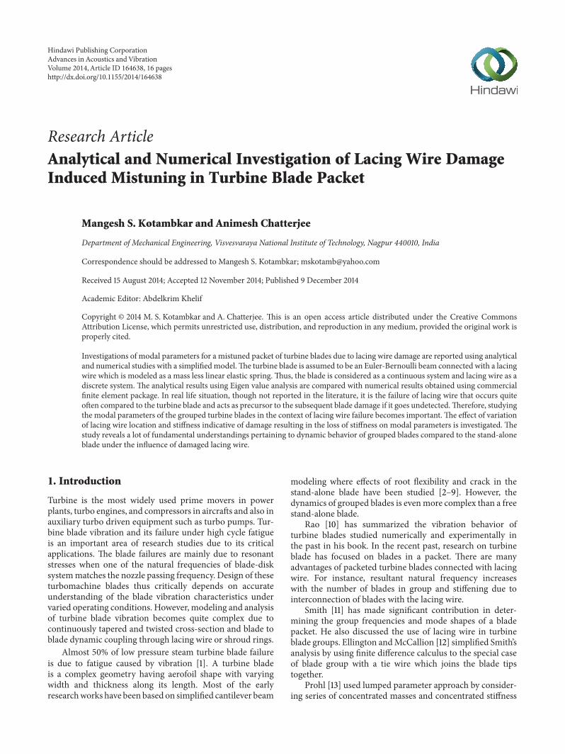
Figure 9 shows partially damaged lacing wire segmentbetween second and third blades whereas the lacing wiresegment between first and second blades is presumed tobe undamaged As a result of damage spring stiffness 119896
2
becomes less than 1198961 In case of complete breakage of this
lacing wire 1198962reduces to zero (Figure 10) A damage severity
factor 120572 can be defined as
120572 =
Δ119896
1198961
where Δ119896 = 1198961minus 1198962 (12)
As lacing wire damage increases 1198962decreases compared to 119896
1
due to whichΔ119896 goes on increasing and thus damage severityfactor 120572 increases from zero to finally one when the lacingwire undergoes full cracking
Advances in Acoustics and Vibration 7
(a) Submode I (b) Submode II (c) Submode III
Figure 7 Submodes of 3rd mode shape
00 02 04 06 08 1018
19
20
21
22
23
24
25
26
27
Submode ISubmode II
Submode III
120573L
120582
Figure 8 Effect of varying stiffness ratios on natural frequencies ofsubmodes of the fundamental mode
k1
k2k2 lt k1
Figure 9 Three blades with one partially damaged lacing wire
k1
k2 = 0
Figure 10 Three blades with fully damagedbroken lacing wire atfree ends
For a typical lacing wire damage frequency determinantequation (11) is evaluatedwith reduced spring stiffness ratio of1205822corresponding to the reduced value of 119896
2= (1minus120572)lowast119896
1The
corresponding frequency values of the modified mistunedsystem for varying degrees of damage severity (120572 varyingbetween zero and one) are presented in Tables 3 4 5 and 6for 120582 = 01 025 05 and 10
It can be noted from Tables 3 4 5 and 6 that all thesubmode frequencies in all the modes are reducing with theincrease in lacingwire damage severity120572 from0 to 1Thedropin submode frequencies is more in the tuned system withthe higher value of 120582 It can be further observed that dropin submodes frequency of the fundamental mode is highercompared to submodes frequency of the higher modes
Therefore effect of lacing wire damage on mistuning hasbeen shown in Figures 11(a)ndash11(d) for the submodes of thefundamental mode only for tuned systems 120582 = 01 025 05and 10
8 Advances in Acoustics and Vibration
Table 3 Effect of mistuning due to lacing wire damage (for 120582 = 01)on natural frequencies
Mode Submode 120573119871 values120572 = 0 120572 = 02 120572 = 04 120572 = 06 120572 = 08 120572 = 10
1I 18751 18751 18751 18751 18751 18751II 19189 19140 19073 18987 18879 18751III 19978 19872 19780 19703 19642 19597
2I 46941 46941 46941 46941 46941 46941II 46970 46967 46962 46956 46949 46941III 47028 47020 47013 47007 47002 46999
3I 78548 78548 78548 78548 78548 78548II 78554 78553 78552 78551 78549 78548III 78566 78564 78563 78562 78561 78560
Table 4 Effect ofmistuning due to lacingwire damage (for 120582= 025)on natural frequencies
Mode Submode 120573119871 values120572 = 0 120572 = 02 120572 = 04 120572 = 06 120572 = 08 120572 = 10
1I 18751 18751 18751 18751 18751 18751II 19790 19678 19526 19323 19065 18751III 21448 21239 21052 20895 20771 20675
2I 46941 46941 46941 46941 46941 46941II 47014 47005 46994 46979 46962 46941III 47160 47139 47121 47107 47095 47087
3I 78548 78548 78548 78548 78548 78548II 78563 78561 78559 78556 78552 78548III 78594 78590 78586 78583 78580 78579
Table 5 Effect of mistuning due to lacing wire damage (for 120582 = 05)on natural frequencies
Mode Submode 120573119871 values120572 = 0 120572 = 02 120572 = 04 120572 = 06 120572 = 08 120572 = 10
1I 18751 18751 18751 18751 18751 18751II 20675 20480 20211 19844 19363 18751III 23318 23005 22721 22479 22285 22135
2I 46941 46941 46941 46941 46941 46941II 47087 47070 47047 47018 46982 46941III 47383 47340 47304 47274 47251 47234
3I 78548 78548 78548 78548 78548 78548II 78579 78575 78570 78564 78556 78548III 78641 78632 78624 78618 78613 78610
From Tables 3 4 5 and 6 and corresponding Figures11(a)ndash11(d) it can be noted that with a damage in a lacingwire the first submode frequency is invariant but othersubmode frequencies vary and in fact they decrease whencompared to a blade packet with no damage in lacingwire The change in natural frequencies is augmented withstiffer connection (ie higher 120582) and is more prominent infundamental mode compared to higher modes
Table 6 Effect of mistuning due to lacing wire damage (for 120582 = 1)on natural frequencies
Mode Submode 120573119871 values120572 = 0 120572 = 02 120572 = 04 120572 = 06 120572 = 08 120572 = 10
1I 18751 18751 18751 18751 18751 18751II 22135 21824 21384 20768 19917 18751III 25932 25514 25129 24797 24526 24314
2I 46941 46941 46941 46941 46941 46941II 47234 47200 47154 47095 47023 46941III 47836 47749 47675 47615 47568 47533
3I 78548 78548 78548 78548 78548 78548II 78610 78603 78593 78580 78565 78548III 78735 78718 78702 78689 78680 78548
Table 7 Natural frequencies (120573119871 values) of the tuned blade packetwith varying stiffness ratios (lacing wire at 23rd of blade span)
Mode Submode 120582 = 01 120582 = 025 120582 = 05 120582 = 10
1I 18751 18751 18751 18751II 18886 19082 19396 19978III 19146 19694 20511 21884
2I 46941 46941 46941 46941II 46946 46954 46967 46993III 46957 46980 47019 47065
3I 78548 78548 78548 78548II 78550 78554 78560 78573III 78555 78567 78586 78625
It is interesting to note that with the complete breakage inthe lacing wire one of the values among the cluster of threevalues gets repeated for all the submodes as shown in the lastcolumn of Tables 3 4 5 and 6The systemwith broken lacingwire gets converted to two configurations that is one withstand-alone blade and the other with two blades connectedwith lacing wire as shown in Figure 10 Thus the firstsubmode frequency of the fundamental mode appears twicefor the two subsystems created due to brakeage of lacing wireconnection This is revealed clearly in Figures 11(a)ndash11(d)where the second submode frequency converges to the firstsubmode frequency This finding may be used for detectingcomplete breakage of lacing wire
5 Lacing Wire Connection withinthe Span of Blades
In order to investigate the effect of lacing wire location onthe natural frequencies of grouped blades the study is furtherextended for the three blade packets with the lacing wireconnected at a location inside the span of the blade as shownin Figure 12
The analytical model formulation is carried out in a waysimilar to that for lacing wires at the tip with the exception
Advances in Acoustics and Vibration 9
00 02 04 06 08 1018
19
20
21
22
23
24
25
26
27120573L
Damage severity index 120572
Submode ISubmode II
Submode III
(a)
Damage severity index 120572
00 02 04 06 08 1018
19
20
21
22
23
24
25
26
27
Submode ISubmode II
Submode III
120573L
(b)
00 02 04 06 08 1018
19
20
21
22
23
24
25
26
27
120573L
Damage severity index 120572
Submode ISubmode II
Submode III
(c)
Damage severity index 120572
00 02 04 06 08 1018
19
20
21
22
23
24
25
26
27
Submode ISubmode II
Submode III
120573L
(d)
Figure 11 Mistuning effect on frequency of submodes of packet of blades with lacing wire at the blade tip for (a) 120582 = 01 (b) 120582 = 025 (c) 120582 =05 and (d) 120582 = 10
that each beam is divided into two beams at the interface ofthe location of the lacing wire spring connection with thebeam Thus each of the blades has two segments and eightconstants in the mode shape description with four in eachsegment These coefficients are reduced to four in numberemploying the four boundary conditions two at blade rootand another two at blade tip There are four equations dueto compatibility conditions at lacing wire location for eachof the blades and as a result there are twelve equations andtwelve unknowns to be obtained for the grouped systemFor nontrivial solution the determinant of the coefficientsis zero and the expansion of the determinant leads to thecharacteristic equation
BCrsquos are as follows for the upper bladersquos left segment oflength ldquoardquo
at 1199091= 0 119910
1(1199091) = 0 and 1199101015840
1(1199091) = 0 therefore 119862
3=
minus1198621and 119862
4= minus1198622
For the right segment of length ldquobrdquo
at 1199092= 0 11991010158401015840
2(1199092) = 0 and 119910101584010158401015840
2(1199092) = 0 therefore
1198627= 1198625and 119862
8= 1198626
Similarly for middle and lower blades we get
11986211= minus1198629 119862
12= minus11986210 119862
15= 11986213
11986216= 11986214
11986219= minus11986217 119862
20= minus11986218 119862
23= 11986221
(13)
11986224= 11986222 (14)
10 Advances in Acoustics and Vibration
However four equations due to compatibility conditions ofdisplacement slope BM and SF at the location of lacing wireconnection for the upper blade are as follows
1198841(119886)
= 1198842(minus119887)
1198841015840
1(119886)= 1198841015840
2(minus119887)
11988410158401015840
1(119886)= 11988410158401015840
2(minus119887)
119884101584010158401015840
1(119886)= 119884101584010158401015840
2(minus119887)+ 11989611198841(119886)
1198621(cosh120573119886 minus cos120573119886) + 119862
2(sinh120573119886 minus sin120573119886)
minus 1198625(cosh120573119887 minus cos120573119887) minus 119862
6(minus sinh120573119887 minus sin120573119887) = 0
1198621(sinh120573119886 + sin120573119886) + 119862
2(cosh120573119886 minus cos120573119886)
minus 1198625(minus sinh120573119887 + sin120573119887) minus 119862
6(cosh120573119887 + cos120573119887) = 0
1198621(cosh120573119886 + cos120573119886) + 119862
2(sinh120573119886 + sin120573119886)
minus 1198625(cosh120573119887 minus cos120573119887) minus 119862
6(minus sinh120573119887 + sin120573119887) = 0
1198621[(sinh120573119886 minus sin120573119886) minus (cosh120573119886 minus cos120573119886) 119896
1
EI1205733]
+ 1198622[(cosh120573119886 + cos120573119886) minus (sinh120573119886 minus sin120573119886) 119896
1
EI1205733]
minus 1198625(minus sinh120573119887 minus sin120573119887) minus 119862
6(cosh120573119887 minus cos120573119887)
minus 1198629(cosh120573119886 minus cos120573119886) 119896
1
EI1205733
+ 11986210(sinh120573119886 minus sin120573119886) 119896
1
EI1205733= 0
(15)
The first three equations of compatibility conditions arethe same for the middle and lower blades whereas (16) ofshear force are different and are given as follows
1198621(cosh120573119886 minus cos120573119886) 119896
1
EI1205733+ 1198622(sinh120573119886 minus sin120573119886) 119896
1
EI1205733
+ 1198629[(sinh120573119886 minus sin120573119886) minus (cosh120573119886 minus cos120573119886) 1198961 + 1198962
EI1205733]
+ 11986210[(cosh120573119886 + cos120573119886) minus (sinh120573119886 minus sin120573119886) 1198961 + 1198962
EI1205733]
minus 11986213(minus sinh120573119887 minus sin120573119887) minus 119862
14(cosh120573119887 minus cos120573119887)
+ 11986217(cosh120573119886 minus cos120573119886) 119896
2
EI1205733
+ 11986218(sinh120573119886 minus sin120573119886) 119896
2
EI1205733= 0
1198629(cosh120573119886 minus cos120573119886) 119896
2
EI1205733+ 11986210(sinh120573119886 minus sin120573119886) 119896
2
EI1205733
+ 11986217[(sinh120573119886 minus sin120573119886) minus (cosh120573119886 minus cos120573119886) 119896
2
EI1205733]
+ 11986218[(cosh120573119886 + cos120573119886) minus (sinh120573119886 minus sin120573119886) 119896
2
EI1205733]
minus 11986221(minus sinh120573119887 minus sin120573119887) minus 119862
22(cosh120573119887 minus cos120573119887) = 0
(16)
These equations can be arranged to get frequency equation indeterminant form as
10038161003816100381610038161003816100381610038161003816100381610038161003816100381610038161003816100381610038161003816100381610038161003816100381610038161003816100381610038161003816100381610038161003816100381610038161003816100381610038161003816100381610038161003816100381610038161003816100381610038161003816100381610038161003816100381610038161003816100381610038161003816100381610038161003816100381610038161003816100381610038161003816100381610038161003816100381610038161003816100381610038161003816100381610038161003816100381610038161003816100381610038161003816100381610038161003816100381610038161003816100381610038161003816100381610038161003816100381610038161003816100381610038161003816100381610038161003816
119877119886
119878119886
minus119875119887
119876119887
0 0 0 0 0 0 0 0
119876119886
119877119886
119878119887
minus119875119887
0 0 0 0 0 0 0 0
119875119886
119876119886
minus119877119887
119878119887
0 0 0 0 0 0 0 0
119878119886minus 119877119886
1205821
(120573119871)3119875119886minus 119878119886
1205821
(120573119871)3
119876119887
minus119877119887
119877119886
1205821
(120573119871)3
119878119886
1205821
(120573119871)3
0 0 0 0 0 0
0 0 0 0 119877119886
119878119886
minus119875119887
119876119887
0 0 0 0
0 0 0 0 119876119886
119877119886
119878119887
minus119875119887
0 0 0 0
0 0 0 0 119875119886
119876119886
minus119877119887
119878119887
0 0 0 0
119877119886
1205821
(120573119871)3
119878119886
1205821
(120573119871)3
0 0 119878119886minus 119877119886
1205821+ 1205822
(120573119871)3
119875119886minus 119878119886
1205821+ 1205822
(120573119871)3
119876119887
minus119877119887
119877119886
1205822
(120573119871)3
119878119886
1205822
(120573119871)3
0 0
0 0 0 0 0 0 0 0 119877119886
119878119886
minus119875119887
119876119887
0 0 0 0 0 0 0 0 119876119886
119877119886
119878119887
minus119875119887
0 0 0 0 0 0 0 0 119875119886
119876119886
minus119877119887
119878119887
0 0 0 0 119877119886
1205822
(120573119871)3
119878119886
1205822
(120573119871)3
0 0 119878119886minus 119877119886
1205822
(120573119871)3119875119886minus 119878119886
1205822
(120573119871)3
119876119887
minus119877119887
10038161003816100381610038161003816100381610038161003816100381610038161003816100381610038161003816100381610038161003816100381610038161003816100381610038161003816100381610038161003816100381610038161003816100381610038161003816100381610038161003816100381610038161003816100381610038161003816100381610038161003816100381610038161003816100381610038161003816100381610038161003816100381610038161003816100381610038161003816100381610038161003816100381610038161003816100381610038161003816100381610038161003816100381610038161003816100381610038161003816100381610038161003816100381610038161003816100381610038161003816100381610038161003816100381610038161003816100381610038161003816100381610038161003816100381610038161003816
= 0
(17)
Advances in Acoustics and Vibration 11
ba
y1 y2
y4
x2
x4
y6x6
x1
x3 y3
x5 y5
k1
k2
Figure 12 Three blades interconnected with lacing wire inside the span
Table 8 Effect of lacing wire damage induced mistuning (for 120582 = 01) on natural frequencies of the blade packet (lacing wire at 23rd of bladespan)
Mode Submode 120573119871 values120572 = 0 120572 = 02 120572 = 04 120572 = 06 120572 = 08 120572 = 10
1I 18751 18751 18751 18751 18751 18751II 18886 18870 18849 18823 18790 18751III 19146 19110 19078 19053 19032 19017
2I 46941 46941 46941 46941 46941 46941II 46946 46946 46945 46944 46942 46941III 46957 46955 46954 46953 46952 46951
3I 78548 78548 78548 78548 78548 78548II 78550 78550 78549 78549 78548 78548III 78555 78555 78554 78553 78553 78553
Table 9 Effect of lacing wire damage induced mistuning (for 120582 = 025) on natural frequencies (lacing wire at 23rd of blade span)
Mode Submode 120573119871 values120572 = 0 120572 = 02 120572 = 04 120572 = 06 120572 = 08 120572 = 10
1I 18751 18751 18751 18751 18751 18751II 19082 19044 18994 18928 18847 18751III 19694 19611 19538 19478 19431 19396
2I 46941 46941 46941 46941 46941 46941II 46954 46952 46950 46948 46945 46941III 46980 46976 46973 46970 46968 46967
3I 78548 78548 78548 78548 78548 78548II 78554 78553 78552 78551 78549 78548III 78567 78565 78563 78562 78561 78560
where 119875119886= cosh120573119871120583 + cos120573119871120583 in which 120583 = 119886119871 is nor-
malized lacing wire location from the root 119876119886= sinh120573119871120583 +
sin120573119871120583 119877119886= cosh120573119871120583 minus cos120573119871120583 and 119878
119886= sinh120573119871120583 minus
sin120573119871120583 and 119875119887= cosh120573119871(1 minus 120583) + cos120573119871(1 minus 120583) in which
1 minus 120583 = 119887119871 119876119887= sinh120573119871(1 minus 120583) + sin120573119871(1 minus 120583) 119877
119887=
cosh120573119871(1 minus 120583) minus cos120573119871(1 minus 120583) and 119878119887= sinh120573119871(1 minus 120583) minus
sin120573119871(1 minus 120583)
51 Lacing Wire Connection at 23rd of the Blade Span Thefirst intermediate position for connection of lacing wire
12 Advances in Acoustics and Vibration
Damage severity index 120572
00 02 04 06 08 1018
19
20
21
22
23
24
25
26
27
Submode ISubmode II
Submode III
120573L
(a)
Damage severity index 120572
00 02 04 06 08 1018
19
20
21
22
23
24
25
26
27
Submode ISubmode II
Submode III
120573L
(b)
Damage severity index 120572
00 02 04 06 08 1018
19
20
21
22
23
24
25
26
27
Submode ISubmode II
Submode III
120573L
(c)
Damage severity index 120572
00 02 04 06 08 1018
19
20
21
22
23
24
25
26
27
Submode ISubmode II
Submode III
120573L
(d)
Figure 13 Mistuning effect on frequency of submodes of packet of blades with lacing wire at 23rd of the blade span for (a) 120582 = 01 (b) 120582 =025 (c) 120582 = 05 and (d) 120582 = 10
Table 10 Effect of lacing wire damage induced mistuning (for 120582 = 05) on natural frequencies (lacing wire at 23rd of blade span)
Mode Submode 120573119871 values120572 = 0 120572 = 02 120572 = 04 120572 = 06 120572 = 08 120572 = 10
1I 18751 18751 18751 18751 18751 18751II 19396 19324 19227 19100 18941 18751III 20511 20364 20235 20128 20043 19978
2I 46941 46941 46941 46941 46941 46941II 46967 46964 46960 46955 46948 46941III 47019 47012 47005 47000 46996 46993
3I 78548 78548 78548 78548 78548 78548II 78560 78559 78557 78554 78551 78548III 78586 78583 78579 78577 78575 78573
Advances in Acoustics and Vibration 13
Table 11 Effect of lacing wire damage induced mistuning (for 120582 = 1) on natural frequencies (lacing wire at 23rd of blade span)
Mode Submode 120573119871 values120572 = 0 120572 = 02 120572 = 04 120572 = 06 120572 = 08 120572 = 10
1I 18751 18751 18751 18751 18751 18751II 19978 19847 19668 19430 19125 18751III 21884 21646 21433 21254 21111 21002
2I 46941 46941 46941 46941 46941 46941II 46993 46987 46979 46968 46956 46941III 47098 47083 47070 47060 47052 47045
3I 78548 78548 78548 78548 78548 78548II 78573 78570 78566 78561 78555 78548III 78625 78617 78611 78606 78602 78599
Table 12 Natural frequencies (120573119871 values) of the tuned blade packet with varying stiffness ratios (lacing wire at mid span)
Mode Submode 120582 = 01 120582 = 025 120582 = 05 120582 = 10
1I 18751 18751 18751 18751II 18803 18880 19006 19249III 18906 19129 19479 20109
2I 46941 46941 46941 46941II 46956 46978 47015 47019III 46985 47052 47162 47275
3I 78548 78548 78548 78548II 78548 78548 78548 78548III 78548 78548 78548 78548
Table 13 Effect of lacing wire damage induced mistuning (for 120582 = 01) on natural frequencies (lacing wire at mid span)
Mode Submode 120573119871 values120572 = 0 120572 = 02 120572 = 04 120572 = 06 120572 = 08 120572 = 10
1I 18751 18751 18751 18751 18751 18751II 18803 18797 18789 18779 18766 18751III 18906 18891 18879 18869 18861 18855
2I 46941 46941 46941 46941 46941 46941II 46956 46954 46952 46949 46945 46941III 46985 46981 46977 46975 46972 46970
3I 78548 78548 78548 78548 78548 78548II 78548 78548 78548 78548 78548 78548III 78548 78548 78548 78548 78548 78548
is considered as 23rd of the blade span (Figure 13) andaccordingly normalized length of the two segments is usedin the frequency equation to get the set of values indicated inTable 7
It is observed from Table 7 that natural frequencies of allthe submodes are reducing with the shifting of location oflacing wire towards the blade root This observation is quiteobvious as the ratio of lacing wire stiffness to blade stiffness 120582will be reducing with the shifting of lacing wires towards theroot of the blade compared to the ratio when lacing wires areat the tip of bladeThis is due to the increase in stiffness of the
blade with the shifting of spring force towards the fixed endcompared to spring force at free endTherefore smaller valueof stiffness ratio goes into calculation for natural frequenciesresulting in a drop in natural frequencies
It is also evident that the reduction in the fundamentalmode frequencies is more compared to the subsequentmodes This is due to the fact that the system stiffnessincreases in higher modes and as a result there is a dropin 120582 Moreover the higher frequencies of submodes in thecluster are more sensitive than earlier as lacing wire stiffnesscontribution is more in higher submodes
14 Advances in Acoustics and Vibration
Damage severity index 120572
00 02 04 06 08 1018
19
20
21
22
23
24
25
26
27
Submode ISubmode II
Submode III
120573L
(a)
Damage severity index 120572
00 02 04 06 08 1018
19
20
21
22
23
24
25
26
27
Submode ISubmode II
Submode III
120573L
(b)
Damage severity index 120572
00 02 04 06 08 1018
19
20
21
22
23
24
25
26
27
Submode ISubmode II
Submode III
120573L
(c)
Damage severity index 120572
00 02 04 06 08 1018
19
20
21
22
23
24
25
26
27
Submode ISubmode II
Submode III
120573L
(d)
Figure 14 Mistuning effect on frequency of submodes of packet of blades with lacing wire at middle of the blade span for (a) 120582 = 01 (b) 120582 =025 (c) 120582 = 05 and (d) 120582 = 10
It is also observed that the first submode frequency inall the modes does not change whereas other frequenciesare getting changed albeit for higher modes the change isthe least On the basis of this result it is concluded thatonly submodes of the fundamental mode can be used as anindicator for lacing wire stiffness reduction
52 Lacing Wire Connection at the Middle of Blade Span Asobserved in the above section natural frequency of all thesubmodes decreases with shifting in location of lacing wireconnection towards blade root It is the fundamental modewhich is observed to be more sensitive to change in locationTo investigate the effect of connection on antinode and node
points of various modes this study is extended with lacingwire connection at the middle of the blade which is close tothe antinode of the second mode of vibration (Figure 14)Table 12 presents the effect of varying stiffness ratio 120582 onnatural frequency of submodes of three modes of vibration
It is clear from Table 12 that the submodes of the secondmode also get affected with the rise in stiffness ratio value likethe submodes of the fundamental mode whereas submodesof the third mode remain unaffected
53 General Comparison Finally a comparative picture ofeffect of lacing wire damage on the change in naturalfrequencies for all three lacing wire positions considered here
Advances in Acoustics and Vibration 15
Sub mode II Sub mode II
Sub mode II
Sub mode III
Sub mode III
LW at blade tipLW at 23rd of span
LW at middle of span
Sub mode III
Sub mode I
Damage severity index 120572
00 02 04 06 08 1018
19
20
21
22
23
24
120573L
Figure 15 Comparison of lacing wire damage induced mistuningin the three different tuned systems with the stiffness ratio of lacingwire 120582 = 05
Table 14 Effect of lacing wire damage induced mistuning (for 120582 =025) on natural frequencies (lacing wire at mid span)
Mode Submode 120573119871 values120572 = 0 120572 = 02 120572 = 04 120572 = 06 120572 = 08 120572 = 10
1I 18751 18751 18751 18751 18751 18751II 18880 18866 18846 18820 18788 18751III 19129 19095 19065 19040 19021 19006
2I 46941 46941 46941 46941 46941 46941II 46978 46974 46968 46960 46951 46941III 47052 47041 47032 47025 47019 47015
3I 78548 78548 78548 78548 78548 78548II 78548 78548 78548 78548 78548 78548III 78548 78548 78548 78548 78548 78548
is presented in Figure 15 where it can be seen that qualitativebehavior remains the same in all three cases and irrespectiveof lacing wire position natural frequencies decrease with thedamage growth and the decrease is the maximum when thelacing wire is at the blade tip (Tables 8 9 10 11 13 14 15 and16)
6 Conclusion
It is established from the investigation of simplified turbineblade group dynamics andmodal characteristics that splittingof natural frequencies in each mode occurs and the numberof frequencies into which split occurs is equal to the numberof blades forming the packet with lacing wire connections Itis found that natural frequencies of the submodes connectedwith fundamental mode can be used as an excellent indicatorof a lacing wire damage in both qualitative and quantitativeways
Table 15 Effect of lacing wire damage induced mistuning (for 120582 =05) on natural frequencies (lacing wire at mid span)
Mode Submode 120573119871 values120572 = 0 120572 = 02 120572 = 04 120572 = 06 120572 = 08 120572 = 10
1I 18751 18751 18751 18751 18751 18751II 19006 18977 18938 18888 18825 18751III 19479 19415 19359 19312 19276 19249
2I 46941 46941 46941 46941 46941 46941II 47015 47006 46995 46980 46962 46941III 47162 47141 47123 47108 47097 47088
3I 78548 78548 78548 78548 78548 78548II 78548 78548 78548 78548 78548 78548III 78548 78548 78548 78548 78548 78548
Table 16 Effect of lacing wire damage inducedmistuning (for 120582 = 1)on natural frequencies (lacing wire at mid span)
Mode Submode 120573119871 values120572 = 0 120572 = 02 120572 = 04 120572 = 06 120572 = 08 120572 = 10
1I 18751 18751 18751 18751 18751 18751II 19249 19193 19118 19020 18898 18751III 20109 19996 19896 19813 19748 19698
2I 46941 46941 46941 46941 46941 46941II 47019 47071 47048 47019 46983 46941III 47275 47340 47304 47275 47252 47235
3I 78548 78548 78548 78548 78548 78548II 78548 78548 78548 78548 78548 78548III 78548 78548 78548 78548 78548 78548
Another interesting observation is that though multiplefrequencies remain the same in number these frequenciesspread out with stiffening of lacing wire The effect is mostprominent when the lacing wire is at the blade tip Effect inhigher mode frequencies is relatively much smaller and alsodepends on the position of the lacing wire with respect to theantinodes of the mode shapesThe first mode frequencies aretherefore suggested to be considered for the damage diagnosisin turbine blade packet
Conflict of Interests
The authors declare that there is no conflict of interestsregarding the publication of this paper
Acknowledgments
The author is thankful to the research review committee ofthe institute for its critical queries in the pursuit of answers forthose queries resulting in this fundamental workThe authoralso acknowledges the help extended by faculty colleagueDr Arun kumar Singh for his encouragement in learningMathematica and Origin software
16 Advances in Acoustics and Vibration
References
[1] N K Mukhopadhyay S G Chowdhury G Das I ChattorajS K Das and D K Bhattacharya ldquoAn investigation of the fail-ure of low pressure steam turbine bladesrdquo Engineering FailureAnalysis vol 5 no 3 pp 181ndash193 1998
[2] G Gounaris andA Dimarogonas ldquoA finite element of a crackedprismatic beam for structural analysisrdquo Computers and Struc-tures vol 28 no 3 pp 309ndash313 1988
[3] W M Ostachowicz and M Krawczuk ldquoAnalysis of the effect ofcracks on the natural frequencies of a cantilever beamrdquo Journalof Sound and Vibration vol 150 no 2 pp 191ndash201 1991
[4] P Gudmundson ldquoEigenfrequency changes of structures due tocracks notches or other geometrical changesrdquo Journal of theMechanics and Physics of Solids vol 30 no 5 pp 339ndash353 1982
[5] T G Chondros andA D Dimarogonas ldquoVibration of a crackedcantilever beamrdquo Journal of Vibration andAcoustics vol 120 no3 pp 742ndash746 1998
[6] B P Nandwana and S K Maiti ldquoDetection of the location andsize of a crack in stepped cantilever beams based on measure-ments of natural frequenciesrdquo Journal of Sound and Vibrationvol 203 no 3 pp 435ndash446 1997
[7] R Tiwari and N N Dhawade ldquoLocalization and criticality of acrack in an Euler-Bernoulli beam based on modal characteris-ticsrdquo Advances in Vibration Engineering vol 5 no 3 2006
[8] K H Low ldquoComparative study of the eigenvalue solutionsfor mass-loaded beams under classical boundary conditionsrdquoInternational Journal of Mechanical Sciences vol 43 no 1 pp237ndash244 2001
[9] D Wang ldquoVibration and sensitivity analysis of a beam witha lumped mass of translational and rotary inertiasrdquo Journal ofVibration and Acoustics Transactions of the ASME vol 134 no3 Article ID 034502 2012
[10] J S Rao Turbomachine Blade Vibration New Age InternationalPublisher 2010
[11] D M Smith ldquoVibration of turbine blades in packetsrdquo in Pro-ceedings of the 7th International Congress for Applied Mechanicsp 178 London UK 1948
[12] J P Ellington andHMcCallion ldquoThe vibration of laced turbinebladesrdquo Journal of the Royal Aeronautical Society vol 61 p 5631957
[13] M A Prohl ldquoA method for calculating vibration frequency andstress of a banded group of turbine bucketsrdquo Transactions of theASME vol 80 p 169 1958
[14] J S Rao ldquoBlade Group Forced Vibration-Computer ProgramrdquoTech Memo 76 WRL M23 Rochester Institute of TechnologyRochester NY USA 1976
[15] G R Bajaj Free vibration of packeted turbine bladesmdashcoupledbending-bending-torsion modes [MS thesis] Indian Institute ofTechnology Kanpur Kanpur India 1974
[16] J Thomas and H T Belek ldquoFree vibration of blade packetsrdquoJournal of Mechanical Engineering Science vol 19 no 1 p 131977
[17] A L Salama and M Petyt ldquoDynamic response of packets ofblades by the finite element methodrdquo Journal of MechanicalDesign vol 100 no 4 pp 660ndash666 1978
[18] H S Lim and H H Yoo ldquoModal analysis of a multi-blade sys-tem undergoing rotational motionrdquo Journal of MechanicalScience and Technology vol 23 no 8 pp 2051ndash2058 2009
[19] H S Lim J Chung andHH Yoo ldquoModal analysis of a rotatingmulti-packet blade systemrdquo Journal of Sound and Vibration vol325 no 3 pp 513ndash531 2009
[20] D J Ewins ldquoThe effects of detuning upon the forced vibrationsof bladed disksrdquo Journal of Sound and Vibration vol 9 no 1 pp65ndash84 1969
[21] S-T Wei and C Pierre ldquoLocalization phenomena in mistunedassemblies with cyclic symmetry Part II forced vibrationsrdquoJournal of Vibration Acoustics Stress and Reliability in Designvol 110 no 4 pp 439ndash449 1988
[22] M P Castanier and C Pierre ldquoModeling and analysis of mis-tuned bladed disk vibration status and emerging directionsrdquoJournal of Propulsion and Power vol 22 no 2 pp 384ndash3962006
[23] J Hou ldquoCracking-induced mistuning in bladed disksrdquo AIAAJournal vol 44 no 11 pp 2542ndash2546 2006
[24] B-W Huang and J-H Kuang ldquoVariation in the stability of arotating blade disk with a local crack defectrdquo Journal of Soundand Vibration vol 294 no 3 pp 486ndash502 2006
[25] X Fang J Tang E Jordan and K D Murphy ldquoCrack inducedvibration localization in simplified bladed-disk structuresrdquoJournal of Sound and Vibration vol 291 no 1-2 pp 395ndash4182006
[26] A Saito M P Castanier and C Pierre ldquoEffects of a crackedblade on mistuned turbine engine rotor vibrationrdquo Journal ofVibration and Acoustics vol 131 no 6 Article ID 061006 9pages 2009
International Journal of
AerospaceEngineeringHindawi Publishing Corporationhttpwwwhindawicom Volume 2014
RoboticsJournal of
Hindawi Publishing Corporationhttpwwwhindawicom Volume 2014
Hindawi Publishing Corporationhttpwwwhindawicom Volume 2014
Active and Passive Electronic Components
Control Scienceand Engineering
Journal of
Hindawi Publishing Corporationhttpwwwhindawicom Volume 2014
International Journal of
RotatingMachinery
Hindawi Publishing Corporationhttpwwwhindawicom Volume 2014
Hindawi Publishing Corporation httpwwwhindawicom
Journal ofEngineeringVolume 2014
Submit your manuscripts athttpwwwhindawicom
VLSI Design
Hindawi Publishing Corporationhttpwwwhindawicom Volume 2014
Hindawi Publishing Corporationhttpwwwhindawicom Volume 2014
Shock and Vibration
Hindawi Publishing Corporationhttpwwwhindawicom Volume 2014
Civil EngineeringAdvances in
Acoustics and VibrationAdvances in
Hindawi Publishing Corporationhttpwwwhindawicom Volume 2014
Hindawi Publishing Corporationhttpwwwhindawicom Volume 2014
Electrical and Computer Engineering
Journal of
Advances inOptoElectronics
Hindawi Publishing Corporation httpwwwhindawicom
Volume 2014
The Scientific World JournalHindawi Publishing Corporation httpwwwhindawicom Volume 2014
SensorsJournal of
Hindawi Publishing Corporationhttpwwwhindawicom Volume 2014
Modelling amp Simulation in EngineeringHindawi Publishing Corporation httpwwwhindawicom Volume 2014
Hindawi Publishing Corporationhttpwwwhindawicom Volume 2014
Chemical EngineeringInternational Journal of Antennas and
Propagation
International Journal of
Hindawi Publishing Corporationhttpwwwhindawicom Volume 2014
Hindawi Publishing Corporationhttpwwwhindawicom Volume 2014
Navigation and Observation
International Journal of
Hindawi Publishing Corporationhttpwwwhindawicom Volume 2014
DistributedSensor Networks
International Journal of

2 Advances in Acoustics and Vibration
to model the blade group A modified Holzer technique wasused to calculate the natural frequencies and mode shapesRao [14] employed energy approach using Hamiltonrsquos prin-ciple to derive the equations of motion and the boundaryconditions
Bajaj [15] has used the finite element method to deter-mine the natural frequencies of packeted blades in coupledbending-bending-torsion modes Thomas and Belek [16]have also used finite element model for a group of bladeswith rectangular cross-section to find modal parametersin the tangential mode Salama and Petyt [17] have usedfinite element model and periodical structural analysis of thetangential vibration of packeted blades both the positions ofthe lacing wire and rotations were taken into account
Lim and Yoo [18] have studied modal analysis of multi-blade system undergoing rotational motion It is reportedthat the increase in rotational speed increases stiffness ofthe system there by increasing the natural frequencies Theyhave also reported that increase in coupling stiffness increasesthe gap between the frequency loci Lim et al [19] have alsoreported the frequency split due to N number of blades inan Np number of packets as NNp + 1 They have consideredtapered cantilever beam and used finite element approach formodal analysis
These research works mainly focused on tuned bladepacket inwhich all the blades are considered to be identical toeach otherHowevermistuningmay exist in the formof bladeto blade variation in structural and geometrical propertiesdue to manufacturing tolerances operational wear and tearor incipient crack growth Effect of mistuning in a bladegroup was first investigated by Ewins [20] Wei and Pierre[21] studied mistuning caused by geometric variations andreported that even a small mistuning in such cases can lead tovibration localization and amplification of stress amplitudesin the blades Castanier and Pierre [22] have presented areview on reduced-order modeling simulation and analysisof the vibration of bladed disks found in gas-turbine enginesin which applications to system identification and design arealso considered An emphasis is placed on key developmentsthat have enabled better prediction and understanding of theforced response of mistuned bladed disks especially withrespect to assessing and mitigating the harmful impact ofmistuning on blade vibration stress increases and attendanthigh cycle fatigue
Hou [23]workedwith lumped parametermodel inwhichthe local degradation in stiffness due to blade crack isexpressed with a flexibility matrix Effect of near root bladecrack on stability of a packeted blade has been investigated byHuang andKuang [24] Fang et al [25] analysed themistunedsystem as cantilever beams interconnected with springs andused fracture mechanics to determine crack induced stiffnessloss in a beam (Figure 4) It is reported that crack in the blademay not cause a significant frequency change but it may leadto forced vibration localization in a periodic structure underloss of cyclic symmetry Saito et al [26] considered crack asa nonlinear stiffness and used reduced order modeling forstudying the effect of blade damage on vibration responsecharacteristics
In all these research works mistuning has been limited toblade damage only However practical experience shows thatlacingwire damage or breakages aremore frequent than bladedamage during the operational period of the turbine as theycome directly in the path of steam flowgas flowThe damagemay be initially a small surface crack and if left unattended orundetected such damages finally induce stress localization inthe blades leading to blade failure Unfortunately not muchresearch work has been reported in this area particularlyfor blade packets with lacing wire damage The present workfocuses on investigating the effect of lacing wire damage onloss of cyclic symmetry in a blade packet and subsequentcharacteristic changes in the modal properties Both lacingwire at the blade tip and lacing wire at an intermediateposition are considered Effect of relative stiffness of the lacingwire to blade stiffness on the modal spectrum for a tunedand mistuned blade packet is investigated Further studieshave been carried out to characterize modal properties forvarying damage severity and damage at different locations inthe lacing wire loop
2 Modeling and Analysis ofTuned Blade Packet
The turbine blades and disk system is cyclic structure con-sisting of a number of blade packets Each packet has mul-tiple blades interconnected with lacing wire or shroud ringLow pressure turbine stages have long slender blades whichundergo high bending deformation caused by natural fre-quencies in the lower operating range These blades gothrough transient resonant condition at nozzle passing fre-quency [10] In order to limit the vibratory deformationsthese blades of low pressure stages are often stiffened withlacing wire connections These lacing wires are actually rodsof circular cross-sections and are connected with the bladesusing brazing material A typical turbine blade disk systemwith lacing wire interconnection is shown in Figure 1 It canbe seen that the blades are arranged in groups called bladepackets Each blade packet consists of a small number ofinterconnected blades (generally five to seven bladse for lowpressure turbine stages)
The packeted blade disk configuration can be consideredas a domain composed of identical subdomains that havesymmetry with respect to an axis Analysis of only one ofthe subdomains represents the key in obtainingmajor savingsin computation time The subdomain or sector builds up thewhole domain by rotating the subdomain by 2120587119869 where 119869is the number of identical sectors Thus dynamic modelingand analysis is done for one blade packet (Figure 2) only withappropriate boundary conditions and this saves considerableamount of computational work and time
In the present study it is assumed that failure of the lacingwire would occur gradually through crack growth resultingin a reduction in its stiffness Stiffness value of the lacing wireis varied as a ratio to the blade stiffness The objective in thepresent work ismainly to find answers to following questions
Advances in Acoustics and Vibration 3
Lacing wire
Blade
Disk
Figure 1 Turbine blade disk model with lacing wire
Figure 2 One packet of turbine blades with lacing wire
(i) In what way dynamic behavior and modal charac-teristics of free standing blade configuration to inter-connected blade packet configuration differ and howdo these modal characteristics depend on the relativestiffness and location of the lacing wire number ofblades interconnected in a packet and so forth
(ii) What would be the qualitative and quantitative shiftin themodal properties of the affected blade packet incase of a partial damagecrack or complete breakagein a lacing wire
(iii) In what way the changes in the modal properties canbe used to identify the severity and location of thelacing wire damage
A mathematical formulation is presented here for a typicalthree bladed packets with lacing wire positioned at the bladetip initially and subsequently similar analysis for lacing wireat an intermediate position is presented in later sectionsLacing wires are modeled as a spring laterally connectedto the blades and governing differential equations of freevibration are derived using Euler-Bernoulli beam theoryThespring force coming from the lacing wire modifies the shearforce (SF) boundary condition (BC) at the connection pointsand this is the fundamental reason why modal properties ofan interconnected bladed packet are different from those offree standing blades
L
x y1(x)
y2(x)
y3(x)
k1
k2
Figure 3Three blades interconnectedwith lacingwires at free ends
1
ElementsU
k0
k0
Modal analysis of cantilever with spring
Figure 4 Finite element models for three prismatic blades con-nected with lacing wire at the free end
3 Tuned Blade Packet with Lacing WireConnection at the Blade Tip
In the analysis the blades are modeled as parallel cantileverbeams fixed at the disk end (119909 = 0) and restrained bythe springs (representing the lacing wire stiffening) at thefree end (119909 = 119871) as shown in Figure 3 Lacing wires havebeen represented by springs In tuned condition the stiffnessparameter of the springs 119896
1and 1198962will be equal A mistuning
caused by a lacing wire crack or damage can be captured inthe model by setting different values for the stiffness
Eigen value analysis for a single blade connected with alacing wire at the free end is a classical vibration problemfound in the standard book [20] It is extended appropriatelyfor a packet
4 Advances in Acoustics and Vibration
Table 1 Natural frequencies (120573119871) of the tuned blade packet withvarying stiffness ratios
Mode Submode 120582 = 01 120582 = 025 120582 = 05 120582 = 10
1I 18751 18751 18751 18751II 19189 19790 20675 22135III 19978 21448 23318 25932
2I 46941 46941 46941 46941II 46970 47014 47087 47234III 47028 47160 47383 47836
3I 78548 78548 78548 78548II 78554 78563 78579 78610III 78566 78594 78641 78735
Table 2 Comparison of natural frequencies obtained analyticallyand FEM
Mode Submode Frequency in Hz(analytical)
Frequency in Hz(FEM) error
1I 7252 7315 087II 7594 7656 080III 8232 8290 071
2I 45445 45804 078II 45500 45860 078III 45614 45973 078
3I 127245 128490 097II 127263 128510 097III 127306 128550 097
The error in the results of natural frequencies in the submodes of threebending modes of vibration obtained with both methods is less than 1
The equations of motion of free vibration for the bladesare given by
EI1205974119910119894
1205971199094+ 120588119860
1205972119910119894
1205971199052= 0 where 119894 = 1 2 3 (1)
The above equation iswell known as Euler-Bernoulli equationfor a uniform cross-section beam for which the solutionexists in the form
119910 (119909 119905) = 119884119894(119909) sdot 120578 (119905) (2)
where the mode shape function 119884(119909) is expressed as
119884 (119909) = 1198621cosh120573119909 + 119862
2sinh120573119909 + 119862
3cos120573119909 + 119862
4sin120573119909
(3)
With
120573 = (1205962 120588119860
EI)
14
(4)
such that natural frequency can be obtained as
120596 = 1205732radic
EI120588119860
(5)
BCrsquos for the upper blade are as follows
At 1199091= 0 119910
1(1199091) = 0 and 1199101015840
1(1199091) = 0 therefore 119862
3=
minus1198621and 119862
4= minus1198622
At 1199091= 119897 119910101584010158401(1199091) = 0 and 119910101584010158401015840
1(1199091) = 1198961(1199101minus 1199102) give
two equations BM and SF respectively
1198621(cosh120573119897 + cos120573119897) + 119862
2(sinh120573119897 + sin120573119897) = 0 (6)
1198621[(sinh120573119897 minus sin120573119897) minus (cosh120573119897 minus cos120573119897) 119896
1
(120573119871)3
(EI1198713)]
+ 1198622[ (cosh120573119897 + cos120573119897)
minus (sinh120573119897 minus sin120573119897) 1198961
(120573119871)3
(EI1198713)]
+ 1198625(cosh120573119897 minus cos120573119897) 119896
1
(120573119871)3
(EI1198713)
+ 1198626(sinh120573119897 minus sin120573119897) 119896
1
(120573119871)3
(EI1198713)= 0
(7)
BCrsquos for the middle blade are as follows
At 1199092= 0 119910
2(1199092) = 0 and 1199101015840
2(1199092) = 0 therefore 119862
7=
minus1198625and 119862
8= minus1198626
At 1199092= 119897 11991010158401015840
2(1199092) = 0 and 119910101584010158401015840
2(1199092) = 119896
2(1199102minus 1199103) +
1198961(1199102minus1199101) give two equations BMand SF respectively
1198625(cosh120573119897 + cos120573119897) + 119862
6(sinh120573119897 + sin120573119897) = 0 (8)
1198621(cosh120573119897 minus cos120573119897) 119896
1
(120573119871)3
(EI1198713)
+ 1198622(sinh120573119897 minus sin120573119897) 119896
1
(120573119871)3
(EI1198713)
+ 1198625[ (sinh120573119897 minus sin120573119897)
minus (cosh120573119897 minus cos120573119897) 1198961+ 1198962
(120573119871)3
(EI1198713)]
+ 1198626[ (cosh120573119897 + cos120573119897)
minus (sinh120573119897 minus sin120573119897) 1198961+ 1198962
(120573119871)3
(EI1198713)]
Advances in Acoustics and Vibration 5
+ 1198629(cosh120573119897 minus cos120573119897) 119896
2
(120573119871)3
(EI1198713)
+ 11986210(sinh120573119897 minus sin120573119897) 119896
2
(120573119871)3
(EI1198713)= 0
(9)
BCrsquos for the lower blade are as follows
At 1199093= 0 119910
3(1199093) = 0 and 1199101015840
3(1199093) = 0 therefore119862
11=
minus1198629and 119862
12= minus11986210
At 1199093= 119897 119910101584010158403(1199093) = 0 and 119910101584010158401015840
3(1199093) = 1198962(1199103minus 1199102)l
1198629(cosh120573119897 + cos120573119897) + 119862
10(sinh120573119897 + sin120573119897) = 0
1198625(cosh120573119897 minus cos120573119897) 119896
2
(120573119871)3
(EI1198713)
+ 1198626(sinh120573119897 minus sin120573119897) 119896
2
(120573119871)3
(EI1198713)
+ 1198629[ (sinh120573119897 minus sin120573119897)
minus (cosh120573119897 minus cos120573119897) 1198962
(120573119871)3
(EI1198713)]
+ 11986210[ (cosh120573119897 + cos120573119897)
minus (sinh120573119897 minus sin120573119897) 1198962
(120573119871)3
(EI1198713)] = 0
(10)
Using the above equations one gets the frequency equationin a determinant form as
1003816100381610038161003816100381610038161003816100381610038161003816100381610038161003816100381610038161003816100381610038161003816100381610038161003816100381610038161003816100381610038161003816100381610038161003816100381610038161003816100381610038161003816100381610038161003816100381610038161003816100381610038161003816100381610038161003816100381610038161003816
119875 119876 0 0 0 0
119878 minus
1205821119877
(120573119871)3119875 minus
1205821119878
(120573119871)3
1205821119877
(120573119871)3
1205821119878
(120573119871)3
0 0
0 0 119875 119876 0 0
1205821119877
(120573119871)3
1205821119878
(120573119871)3
119878 minus
(1205821+ 1205822) 119877
(120573119871)3
119875 minus
(1205821+ 1205822) 119878
(120573119871)3
1205822119877
(120573119871)3
1205822119878
(120573119871)3
0 0 0 0 119875 119876
0 0
1205822119877
(120573119871)3
1205822119878
(120573119871)3
119878 minus
1205822119877
(120573119871)3119875 minus
1205822119878
(120573119871)3
1003816100381610038161003816100381610038161003816100381610038161003816100381610038161003816100381610038161003816100381610038161003816100381610038161003816100381610038161003816100381610038161003816100381610038161003816100381610038161003816100381610038161003816100381610038161003816100381610038161003816100381610038161003816100381610038161003816100381610038161003816
= 0 (11)
where 119875 = cosh120573119871 + cos120573119871 119876 = sinh120573119871 + sin120573119871 119877 =
cosh120573119871 minus cos120573119871 119878 = sinh120573119871 minus sin120573119871 and 120582119894= 119896119894(EI1198713)
Since EI1198713 is a measure of flexural stiffness of a beam theparameter represents the stiffness ratio between the lacingwire and the cantilever beam
Although in the present analytical work we have con-sidered three blades the same procedures can be extendedfor a blade packet having more numbers of blades Thedeterminant in (11) is a function of two primary variables120573119871 and 120582
119894 Since all the lacing wire segments are identical
in undamaged state equating the determinant to zero in(11) provides the set of natural frequencies for a tuned bladepacket for a given value of stiffness ratio 120582
119894 Table 1 presents
the natural frequency values of the blade packet for a range ofstiffness ratios (120582 = 01 025 05 and 10)
The numerical approach using finite element analysis(FEA) is carried out with the commercial software ANSYS130 The solid45 brick element is used for meshing the bladeand combin14 element is used for lacing wire The meshsensitivity analysis is done to ensure the optimum size ofelement The results are compared for 120582 = 01 in Table 2
The error in the results of natural frequencies in thesubmodes of three bendingmodes of vibration obtained withboth methods is less than 1
Corresponding mode shapes (for 120582 = 01) for the threesubmodes in case of first second and third modes arepresented in Figures 5 6 and 7
In Figure 5(a) all the blades are vibrating in phase whichmeans springs are not undergoing any deformation and thusare not contributing any restraints on the beams This is whythe first submode natural frequency is the same as the naturalfrequency of the free standing blades
In Figure 5(b) outer blades are out of phase whereasthe central blade remains undeformed In Figure 5(c) outerblades are in phase and the central blade is out of phase Thisgives higher frequency values for submodes II and III
The following characteristics can be noted from thefrequency values as given in Table 1
(i) When blades are grouped into a blade packet eachmode of the free standing blade gets split in several(three in this case) submodes The first submodenatural frequency is the same as the firstmode natural
6 Advances in Acoustics and Vibration
(a) Submode I (b) Submode II (c) Submode III
Figure 5 Submodes of 1st mode shape
(a) Submode I (b) Submode II (c) Submode III
Figure 6 Submodes of 2nd mode shape
frequency of the stand-alone blade and the remainingsubmode frequencies are additional in the frequencyspectrum
(ii) The second and third submode natural frequenciesare higher than the basic mode natural frequencyand their difference from the basic mode naturalfrequency is directly related to the stiffness ratio 120582As 120582 increases these submode frequencies increasehigher and higher (Figure 8) Thus the values of thesecond and higher submodes give an indication ofthe relative strength of the lacing wire stiffness withrespect to that of the blade and hence any changein lacing wire stiffness due to a crack or damage isexpected to change these frequencies
(iii) The submode natural frequencies of the first modeare more sensitive to the presence of lacing wire thanthe frequencies in higher modes This is due to theposition of lacing wire at the blade tip which happensto be the antinode of first mode shape Thus a springat the blade tip constrains the first mode tomaximumextent and thereby changes the frequencies associatedwith the first mode Figure 8 shows the same quitedistinctly
4 Analysis of Mistuned Blade Packet due toDamage in Lacing Wire
During operation lacing wire often develops crack result-ing in stiffness loss When the lacing wire undergoes fullcracking the spring stiffness becomes zero This reductionin stiffness in one of the lacing wire segments introducesmistuning in the blade packet This modifies the natural fre-quencies of the blade packet which is investigated andpresented below
Figure 9 shows partially damaged lacing wire segmentbetween second and third blades whereas the lacing wiresegment between first and second blades is presumed tobe undamaged As a result of damage spring stiffness 119896
2
becomes less than 1198961 In case of complete breakage of this
lacing wire 1198962reduces to zero (Figure 10) A damage severity
factor 120572 can be defined as
120572 =
Δ119896
1198961
where Δ119896 = 1198961minus 1198962 (12)
As lacing wire damage increases 1198962decreases compared to 119896
1
due to whichΔ119896 goes on increasing and thus damage severityfactor 120572 increases from zero to finally one when the lacingwire undergoes full cracking
Advances in Acoustics and Vibration 7
(a) Submode I (b) Submode II (c) Submode III
Figure 7 Submodes of 3rd mode shape
00 02 04 06 08 1018
19
20
21
22
23
24
25
26
27
Submode ISubmode II
Submode III
120573L
120582
Figure 8 Effect of varying stiffness ratios on natural frequencies ofsubmodes of the fundamental mode
k1
k2k2 lt k1
Figure 9 Three blades with one partially damaged lacing wire
k1
k2 = 0
Figure 10 Three blades with fully damagedbroken lacing wire atfree ends
For a typical lacing wire damage frequency determinantequation (11) is evaluatedwith reduced spring stiffness ratio of1205822corresponding to the reduced value of 119896
2= (1minus120572)lowast119896
1The
corresponding frequency values of the modified mistunedsystem for varying degrees of damage severity (120572 varyingbetween zero and one) are presented in Tables 3 4 5 and 6for 120582 = 01 025 05 and 10
It can be noted from Tables 3 4 5 and 6 that all thesubmode frequencies in all the modes are reducing with theincrease in lacingwire damage severity120572 from0 to 1Thedropin submode frequencies is more in the tuned system withthe higher value of 120582 It can be further observed that dropin submodes frequency of the fundamental mode is highercompared to submodes frequency of the higher modes
Therefore effect of lacing wire damage on mistuning hasbeen shown in Figures 11(a)ndash11(d) for the submodes of thefundamental mode only for tuned systems 120582 = 01 025 05and 10
8 Advances in Acoustics and Vibration
Table 3 Effect of mistuning due to lacing wire damage (for 120582 = 01)on natural frequencies
Mode Submode 120573119871 values120572 = 0 120572 = 02 120572 = 04 120572 = 06 120572 = 08 120572 = 10
1I 18751 18751 18751 18751 18751 18751II 19189 19140 19073 18987 18879 18751III 19978 19872 19780 19703 19642 19597
2I 46941 46941 46941 46941 46941 46941II 46970 46967 46962 46956 46949 46941III 47028 47020 47013 47007 47002 46999
3I 78548 78548 78548 78548 78548 78548II 78554 78553 78552 78551 78549 78548III 78566 78564 78563 78562 78561 78560
Table 4 Effect ofmistuning due to lacingwire damage (for 120582= 025)on natural frequencies
Mode Submode 120573119871 values120572 = 0 120572 = 02 120572 = 04 120572 = 06 120572 = 08 120572 = 10
1I 18751 18751 18751 18751 18751 18751II 19790 19678 19526 19323 19065 18751III 21448 21239 21052 20895 20771 20675
2I 46941 46941 46941 46941 46941 46941II 47014 47005 46994 46979 46962 46941III 47160 47139 47121 47107 47095 47087
3I 78548 78548 78548 78548 78548 78548II 78563 78561 78559 78556 78552 78548III 78594 78590 78586 78583 78580 78579
Table 5 Effect of mistuning due to lacing wire damage (for 120582 = 05)on natural frequencies
Mode Submode 120573119871 values120572 = 0 120572 = 02 120572 = 04 120572 = 06 120572 = 08 120572 = 10
1I 18751 18751 18751 18751 18751 18751II 20675 20480 20211 19844 19363 18751III 23318 23005 22721 22479 22285 22135
2I 46941 46941 46941 46941 46941 46941II 47087 47070 47047 47018 46982 46941III 47383 47340 47304 47274 47251 47234
3I 78548 78548 78548 78548 78548 78548II 78579 78575 78570 78564 78556 78548III 78641 78632 78624 78618 78613 78610
From Tables 3 4 5 and 6 and corresponding Figures11(a)ndash11(d) it can be noted that with a damage in a lacingwire the first submode frequency is invariant but othersubmode frequencies vary and in fact they decrease whencompared to a blade packet with no damage in lacingwire The change in natural frequencies is augmented withstiffer connection (ie higher 120582) and is more prominent infundamental mode compared to higher modes
Table 6 Effect of mistuning due to lacing wire damage (for 120582 = 1)on natural frequencies
Mode Submode 120573119871 values120572 = 0 120572 = 02 120572 = 04 120572 = 06 120572 = 08 120572 = 10
1I 18751 18751 18751 18751 18751 18751II 22135 21824 21384 20768 19917 18751III 25932 25514 25129 24797 24526 24314
2I 46941 46941 46941 46941 46941 46941II 47234 47200 47154 47095 47023 46941III 47836 47749 47675 47615 47568 47533
3I 78548 78548 78548 78548 78548 78548II 78610 78603 78593 78580 78565 78548III 78735 78718 78702 78689 78680 78548
Table 7 Natural frequencies (120573119871 values) of the tuned blade packetwith varying stiffness ratios (lacing wire at 23rd of blade span)
Mode Submode 120582 = 01 120582 = 025 120582 = 05 120582 = 10
1I 18751 18751 18751 18751II 18886 19082 19396 19978III 19146 19694 20511 21884
2I 46941 46941 46941 46941II 46946 46954 46967 46993III 46957 46980 47019 47065
3I 78548 78548 78548 78548II 78550 78554 78560 78573III 78555 78567 78586 78625
It is interesting to note that with the complete breakage inthe lacing wire one of the values among the cluster of threevalues gets repeated for all the submodes as shown in the lastcolumn of Tables 3 4 5 and 6The systemwith broken lacingwire gets converted to two configurations that is one withstand-alone blade and the other with two blades connectedwith lacing wire as shown in Figure 10 Thus the firstsubmode frequency of the fundamental mode appears twicefor the two subsystems created due to brakeage of lacing wireconnection This is revealed clearly in Figures 11(a)ndash11(d)where the second submode frequency converges to the firstsubmode frequency This finding may be used for detectingcomplete breakage of lacing wire
5 Lacing Wire Connection withinthe Span of Blades
In order to investigate the effect of lacing wire location onthe natural frequencies of grouped blades the study is furtherextended for the three blade packets with the lacing wireconnected at a location inside the span of the blade as shownin Figure 12
The analytical model formulation is carried out in a waysimilar to that for lacing wires at the tip with the exception
Advances in Acoustics and Vibration 9
00 02 04 06 08 1018
19
20
21
22
23
24
25
26
27120573L
Damage severity index 120572
Submode ISubmode II
Submode III
(a)
Damage severity index 120572
00 02 04 06 08 1018
19
20
21
22
23
24
25
26
27
Submode ISubmode II
Submode III
120573L
(b)
00 02 04 06 08 1018
19
20
21
22
23
24
25
26
27
120573L
Damage severity index 120572
Submode ISubmode II
Submode III
(c)
Damage severity index 120572
00 02 04 06 08 1018
19
20
21
22
23
24
25
26
27
Submode ISubmode II
Submode III
120573L
(d)
Figure 11 Mistuning effect on frequency of submodes of packet of blades with lacing wire at the blade tip for (a) 120582 = 01 (b) 120582 = 025 (c) 120582 =05 and (d) 120582 = 10
that each beam is divided into two beams at the interface ofthe location of the lacing wire spring connection with thebeam Thus each of the blades has two segments and eightconstants in the mode shape description with four in eachsegment These coefficients are reduced to four in numberemploying the four boundary conditions two at blade rootand another two at blade tip There are four equations dueto compatibility conditions at lacing wire location for eachof the blades and as a result there are twelve equations andtwelve unknowns to be obtained for the grouped systemFor nontrivial solution the determinant of the coefficientsis zero and the expansion of the determinant leads to thecharacteristic equation
BCrsquos are as follows for the upper bladersquos left segment oflength ldquoardquo
at 1199091= 0 119910
1(1199091) = 0 and 1199101015840
1(1199091) = 0 therefore 119862
3=
minus1198621and 119862
4= minus1198622
For the right segment of length ldquobrdquo
at 1199092= 0 11991010158401015840
2(1199092) = 0 and 119910101584010158401015840
2(1199092) = 0 therefore
1198627= 1198625and 119862
8= 1198626
Similarly for middle and lower blades we get
11986211= minus1198629 119862
12= minus11986210 119862
15= 11986213
11986216= 11986214
11986219= minus11986217 119862
20= minus11986218 119862
23= 11986221
(13)
11986224= 11986222 (14)
10 Advances in Acoustics and Vibration
However four equations due to compatibility conditions ofdisplacement slope BM and SF at the location of lacing wireconnection for the upper blade are as follows
1198841(119886)
= 1198842(minus119887)
1198841015840
1(119886)= 1198841015840
2(minus119887)
11988410158401015840
1(119886)= 11988410158401015840
2(minus119887)
119884101584010158401015840
1(119886)= 119884101584010158401015840
2(minus119887)+ 11989611198841(119886)
1198621(cosh120573119886 minus cos120573119886) + 119862
2(sinh120573119886 minus sin120573119886)
minus 1198625(cosh120573119887 minus cos120573119887) minus 119862
6(minus sinh120573119887 minus sin120573119887) = 0
1198621(sinh120573119886 + sin120573119886) + 119862
2(cosh120573119886 minus cos120573119886)
minus 1198625(minus sinh120573119887 + sin120573119887) minus 119862
6(cosh120573119887 + cos120573119887) = 0
1198621(cosh120573119886 + cos120573119886) + 119862
2(sinh120573119886 + sin120573119886)
minus 1198625(cosh120573119887 minus cos120573119887) minus 119862
6(minus sinh120573119887 + sin120573119887) = 0
1198621[(sinh120573119886 minus sin120573119886) minus (cosh120573119886 minus cos120573119886) 119896
1
EI1205733]
+ 1198622[(cosh120573119886 + cos120573119886) minus (sinh120573119886 minus sin120573119886) 119896
1
EI1205733]
minus 1198625(minus sinh120573119887 minus sin120573119887) minus 119862
6(cosh120573119887 minus cos120573119887)
minus 1198629(cosh120573119886 minus cos120573119886) 119896
1
EI1205733
+ 11986210(sinh120573119886 minus sin120573119886) 119896
1
EI1205733= 0
(15)
The first three equations of compatibility conditions arethe same for the middle and lower blades whereas (16) ofshear force are different and are given as follows
1198621(cosh120573119886 minus cos120573119886) 119896
1
EI1205733+ 1198622(sinh120573119886 minus sin120573119886) 119896
1
EI1205733
+ 1198629[(sinh120573119886 minus sin120573119886) minus (cosh120573119886 minus cos120573119886) 1198961 + 1198962
EI1205733]
+ 11986210[(cosh120573119886 + cos120573119886) minus (sinh120573119886 minus sin120573119886) 1198961 + 1198962
EI1205733]
minus 11986213(minus sinh120573119887 minus sin120573119887) minus 119862
14(cosh120573119887 minus cos120573119887)
+ 11986217(cosh120573119886 minus cos120573119886) 119896
2
EI1205733
+ 11986218(sinh120573119886 minus sin120573119886) 119896
2
EI1205733= 0
1198629(cosh120573119886 minus cos120573119886) 119896
2
EI1205733+ 11986210(sinh120573119886 minus sin120573119886) 119896
2
EI1205733
+ 11986217[(sinh120573119886 minus sin120573119886) minus (cosh120573119886 minus cos120573119886) 119896
2
EI1205733]
+ 11986218[(cosh120573119886 + cos120573119886) minus (sinh120573119886 minus sin120573119886) 119896
2
EI1205733]
minus 11986221(minus sinh120573119887 minus sin120573119887) minus 119862
22(cosh120573119887 minus cos120573119887) = 0
(16)
These equations can be arranged to get frequency equation indeterminant form as
10038161003816100381610038161003816100381610038161003816100381610038161003816100381610038161003816100381610038161003816100381610038161003816100381610038161003816100381610038161003816100381610038161003816100381610038161003816100381610038161003816100381610038161003816100381610038161003816100381610038161003816100381610038161003816100381610038161003816100381610038161003816100381610038161003816100381610038161003816100381610038161003816100381610038161003816100381610038161003816100381610038161003816100381610038161003816100381610038161003816100381610038161003816100381610038161003816100381610038161003816100381610038161003816100381610038161003816100381610038161003816100381610038161003816100381610038161003816
119877119886
119878119886
minus119875119887
119876119887
0 0 0 0 0 0 0 0
119876119886
119877119886
119878119887
minus119875119887
0 0 0 0 0 0 0 0
119875119886
119876119886
minus119877119887
119878119887
0 0 0 0 0 0 0 0
119878119886minus 119877119886
1205821
(120573119871)3119875119886minus 119878119886
1205821
(120573119871)3
119876119887
minus119877119887
119877119886
1205821
(120573119871)3
119878119886
1205821
(120573119871)3
0 0 0 0 0 0
0 0 0 0 119877119886
119878119886
minus119875119887
119876119887
0 0 0 0
0 0 0 0 119876119886
119877119886
119878119887
minus119875119887
0 0 0 0
0 0 0 0 119875119886
119876119886
minus119877119887
119878119887
0 0 0 0
119877119886
1205821
(120573119871)3
119878119886
1205821
(120573119871)3
0 0 119878119886minus 119877119886
1205821+ 1205822
(120573119871)3
119875119886minus 119878119886
1205821+ 1205822
(120573119871)3
119876119887
minus119877119887
119877119886
1205822
(120573119871)3
119878119886
1205822
(120573119871)3
0 0
0 0 0 0 0 0 0 0 119877119886
119878119886
minus119875119887
119876119887
0 0 0 0 0 0 0 0 119876119886
119877119886
119878119887
minus119875119887
0 0 0 0 0 0 0 0 119875119886
119876119886
minus119877119887
119878119887
0 0 0 0 119877119886
1205822
(120573119871)3
119878119886
1205822
(120573119871)3
0 0 119878119886minus 119877119886
1205822
(120573119871)3119875119886minus 119878119886
1205822
(120573119871)3
119876119887
minus119877119887
10038161003816100381610038161003816100381610038161003816100381610038161003816100381610038161003816100381610038161003816100381610038161003816100381610038161003816100381610038161003816100381610038161003816100381610038161003816100381610038161003816100381610038161003816100381610038161003816100381610038161003816100381610038161003816100381610038161003816100381610038161003816100381610038161003816100381610038161003816100381610038161003816100381610038161003816100381610038161003816100381610038161003816100381610038161003816100381610038161003816100381610038161003816100381610038161003816100381610038161003816100381610038161003816100381610038161003816100381610038161003816100381610038161003816100381610038161003816
= 0
(17)
Advances in Acoustics and Vibration 11
ba
y1 y2
y4
x2
x4
y6x6
x1
x3 y3
x5 y5
k1
k2
Figure 12 Three blades interconnected with lacing wire inside the span
Table 8 Effect of lacing wire damage induced mistuning (for 120582 = 01) on natural frequencies of the blade packet (lacing wire at 23rd of bladespan)
Mode Submode 120573119871 values120572 = 0 120572 = 02 120572 = 04 120572 = 06 120572 = 08 120572 = 10
1I 18751 18751 18751 18751 18751 18751II 18886 18870 18849 18823 18790 18751III 19146 19110 19078 19053 19032 19017
2I 46941 46941 46941 46941 46941 46941II 46946 46946 46945 46944 46942 46941III 46957 46955 46954 46953 46952 46951
3I 78548 78548 78548 78548 78548 78548II 78550 78550 78549 78549 78548 78548III 78555 78555 78554 78553 78553 78553
Table 9 Effect of lacing wire damage induced mistuning (for 120582 = 025) on natural frequencies (lacing wire at 23rd of blade span)
Mode Submode 120573119871 values120572 = 0 120572 = 02 120572 = 04 120572 = 06 120572 = 08 120572 = 10
1I 18751 18751 18751 18751 18751 18751II 19082 19044 18994 18928 18847 18751III 19694 19611 19538 19478 19431 19396
2I 46941 46941 46941 46941 46941 46941II 46954 46952 46950 46948 46945 46941III 46980 46976 46973 46970 46968 46967
3I 78548 78548 78548 78548 78548 78548II 78554 78553 78552 78551 78549 78548III 78567 78565 78563 78562 78561 78560
where 119875119886= cosh120573119871120583 + cos120573119871120583 in which 120583 = 119886119871 is nor-
malized lacing wire location from the root 119876119886= sinh120573119871120583 +
sin120573119871120583 119877119886= cosh120573119871120583 minus cos120573119871120583 and 119878
119886= sinh120573119871120583 minus
sin120573119871120583 and 119875119887= cosh120573119871(1 minus 120583) + cos120573119871(1 minus 120583) in which
1 minus 120583 = 119887119871 119876119887= sinh120573119871(1 minus 120583) + sin120573119871(1 minus 120583) 119877
119887=
cosh120573119871(1 minus 120583) minus cos120573119871(1 minus 120583) and 119878119887= sinh120573119871(1 minus 120583) minus
sin120573119871(1 minus 120583)
51 Lacing Wire Connection at 23rd of the Blade Span Thefirst intermediate position for connection of lacing wire
12 Advances in Acoustics and Vibration
Damage severity index 120572
00 02 04 06 08 1018
19
20
21
22
23
24
25
26
27
Submode ISubmode II
Submode III
120573L
(a)
Damage severity index 120572
00 02 04 06 08 1018
19
20
21
22
23
24
25
26
27
Submode ISubmode II
Submode III
120573L
(b)
Damage severity index 120572
00 02 04 06 08 1018
19
20
21
22
23
24
25
26
27
Submode ISubmode II
Submode III
120573L
(c)
Damage severity index 120572
00 02 04 06 08 1018
19
20
21
22
23
24
25
26
27
Submode ISubmode II
Submode III
120573L
(d)
Figure 13 Mistuning effect on frequency of submodes of packet of blades with lacing wire at 23rd of the blade span for (a) 120582 = 01 (b) 120582 =025 (c) 120582 = 05 and (d) 120582 = 10
Table 10 Effect of lacing wire damage induced mistuning (for 120582 = 05) on natural frequencies (lacing wire at 23rd of blade span)
Mode Submode 120573119871 values120572 = 0 120572 = 02 120572 = 04 120572 = 06 120572 = 08 120572 = 10
1I 18751 18751 18751 18751 18751 18751II 19396 19324 19227 19100 18941 18751III 20511 20364 20235 20128 20043 19978
2I 46941 46941 46941 46941 46941 46941II 46967 46964 46960 46955 46948 46941III 47019 47012 47005 47000 46996 46993
3I 78548 78548 78548 78548 78548 78548II 78560 78559 78557 78554 78551 78548III 78586 78583 78579 78577 78575 78573
Advances in Acoustics and Vibration 13
Table 11 Effect of lacing wire damage induced mistuning (for 120582 = 1) on natural frequencies (lacing wire at 23rd of blade span)
Mode Submode 120573119871 values120572 = 0 120572 = 02 120572 = 04 120572 = 06 120572 = 08 120572 = 10
1I 18751 18751 18751 18751 18751 18751II 19978 19847 19668 19430 19125 18751III 21884 21646 21433 21254 21111 21002
2I 46941 46941 46941 46941 46941 46941II 46993 46987 46979 46968 46956 46941III 47098 47083 47070 47060 47052 47045
3I 78548 78548 78548 78548 78548 78548II 78573 78570 78566 78561 78555 78548III 78625 78617 78611 78606 78602 78599
Table 12 Natural frequencies (120573119871 values) of the tuned blade packet with varying stiffness ratios (lacing wire at mid span)
Mode Submode 120582 = 01 120582 = 025 120582 = 05 120582 = 10
1I 18751 18751 18751 18751II 18803 18880 19006 19249III 18906 19129 19479 20109
2I 46941 46941 46941 46941II 46956 46978 47015 47019III 46985 47052 47162 47275
3I 78548 78548 78548 78548II 78548 78548 78548 78548III 78548 78548 78548 78548
Table 13 Effect of lacing wire damage induced mistuning (for 120582 = 01) on natural frequencies (lacing wire at mid span)
Mode Submode 120573119871 values120572 = 0 120572 = 02 120572 = 04 120572 = 06 120572 = 08 120572 = 10
1I 18751 18751 18751 18751 18751 18751II 18803 18797 18789 18779 18766 18751III 18906 18891 18879 18869 18861 18855
2I 46941 46941 46941 46941 46941 46941II 46956 46954 46952 46949 46945 46941III 46985 46981 46977 46975 46972 46970
3I 78548 78548 78548 78548 78548 78548II 78548 78548 78548 78548 78548 78548III 78548 78548 78548 78548 78548 78548
is considered as 23rd of the blade span (Figure 13) andaccordingly normalized length of the two segments is usedin the frequency equation to get the set of values indicated inTable 7
It is observed from Table 7 that natural frequencies of allthe submodes are reducing with the shifting of location oflacing wire towards the blade root This observation is quiteobvious as the ratio of lacing wire stiffness to blade stiffness 120582will be reducing with the shifting of lacing wires towards theroot of the blade compared to the ratio when lacing wires areat the tip of bladeThis is due to the increase in stiffness of the
blade with the shifting of spring force towards the fixed endcompared to spring force at free endTherefore smaller valueof stiffness ratio goes into calculation for natural frequenciesresulting in a drop in natural frequencies
It is also evident that the reduction in the fundamentalmode frequencies is more compared to the subsequentmodes This is due to the fact that the system stiffnessincreases in higher modes and as a result there is a dropin 120582 Moreover the higher frequencies of submodes in thecluster are more sensitive than earlier as lacing wire stiffnesscontribution is more in higher submodes
14 Advances in Acoustics and Vibration
Damage severity index 120572
00 02 04 06 08 1018
19
20
21
22
23
24
25
26
27
Submode ISubmode II
Submode III
120573L
(a)
Damage severity index 120572
00 02 04 06 08 1018
19
20
21
22
23
24
25
26
27
Submode ISubmode II
Submode III
120573L
(b)
Damage severity index 120572
00 02 04 06 08 1018
19
20
21
22
23
24
25
26
27
Submode ISubmode II
Submode III
120573L
(c)
Damage severity index 120572
00 02 04 06 08 1018
19
20
21
22
23
24
25
26
27
Submode ISubmode II
Submode III
120573L
(d)
Figure 14 Mistuning effect on frequency of submodes of packet of blades with lacing wire at middle of the blade span for (a) 120582 = 01 (b) 120582 =025 (c) 120582 = 05 and (d) 120582 = 10
It is also observed that the first submode frequency inall the modes does not change whereas other frequenciesare getting changed albeit for higher modes the change isthe least On the basis of this result it is concluded thatonly submodes of the fundamental mode can be used as anindicator for lacing wire stiffness reduction
52 Lacing Wire Connection at the Middle of Blade Span Asobserved in the above section natural frequency of all thesubmodes decreases with shifting in location of lacing wireconnection towards blade root It is the fundamental modewhich is observed to be more sensitive to change in locationTo investigate the effect of connection on antinode and node
points of various modes this study is extended with lacingwire connection at the middle of the blade which is close tothe antinode of the second mode of vibration (Figure 14)Table 12 presents the effect of varying stiffness ratio 120582 onnatural frequency of submodes of three modes of vibration
It is clear from Table 12 that the submodes of the secondmode also get affected with the rise in stiffness ratio value likethe submodes of the fundamental mode whereas submodesof the third mode remain unaffected
53 General Comparison Finally a comparative picture ofeffect of lacing wire damage on the change in naturalfrequencies for all three lacing wire positions considered here
Advances in Acoustics and Vibration 15
Sub mode II Sub mode II
Sub mode II
Sub mode III
Sub mode III
LW at blade tipLW at 23rd of span
LW at middle of span
Sub mode III
Sub mode I
Damage severity index 120572
00 02 04 06 08 1018
19
20
21
22
23
24
120573L
Figure 15 Comparison of lacing wire damage induced mistuningin the three different tuned systems with the stiffness ratio of lacingwire 120582 = 05
Table 14 Effect of lacing wire damage induced mistuning (for 120582 =025) on natural frequencies (lacing wire at mid span)
Mode Submode 120573119871 values120572 = 0 120572 = 02 120572 = 04 120572 = 06 120572 = 08 120572 = 10
1I 18751 18751 18751 18751 18751 18751II 18880 18866 18846 18820 18788 18751III 19129 19095 19065 19040 19021 19006
2I 46941 46941 46941 46941 46941 46941II 46978 46974 46968 46960 46951 46941III 47052 47041 47032 47025 47019 47015
3I 78548 78548 78548 78548 78548 78548II 78548 78548 78548 78548 78548 78548III 78548 78548 78548 78548 78548 78548
is presented in Figure 15 where it can be seen that qualitativebehavior remains the same in all three cases and irrespectiveof lacing wire position natural frequencies decrease with thedamage growth and the decrease is the maximum when thelacing wire is at the blade tip (Tables 8 9 10 11 13 14 15 and16)
6 Conclusion
It is established from the investigation of simplified turbineblade group dynamics andmodal characteristics that splittingof natural frequencies in each mode occurs and the numberof frequencies into which split occurs is equal to the numberof blades forming the packet with lacing wire connections Itis found that natural frequencies of the submodes connectedwith fundamental mode can be used as an excellent indicatorof a lacing wire damage in both qualitative and quantitativeways
Table 15 Effect of lacing wire damage induced mistuning (for 120582 =05) on natural frequencies (lacing wire at mid span)
Mode Submode 120573119871 values120572 = 0 120572 = 02 120572 = 04 120572 = 06 120572 = 08 120572 = 10
1I 18751 18751 18751 18751 18751 18751II 19006 18977 18938 18888 18825 18751III 19479 19415 19359 19312 19276 19249
2I 46941 46941 46941 46941 46941 46941II 47015 47006 46995 46980 46962 46941III 47162 47141 47123 47108 47097 47088
3I 78548 78548 78548 78548 78548 78548II 78548 78548 78548 78548 78548 78548III 78548 78548 78548 78548 78548 78548
Table 16 Effect of lacing wire damage inducedmistuning (for 120582 = 1)on natural frequencies (lacing wire at mid span)
Mode Submode 120573119871 values120572 = 0 120572 = 02 120572 = 04 120572 = 06 120572 = 08 120572 = 10
1I 18751 18751 18751 18751 18751 18751II 19249 19193 19118 19020 18898 18751III 20109 19996 19896 19813 19748 19698
2I 46941 46941 46941 46941 46941 46941II 47019 47071 47048 47019 46983 46941III 47275 47340 47304 47275 47252 47235
3I 78548 78548 78548 78548 78548 78548II 78548 78548 78548 78548 78548 78548III 78548 78548 78548 78548 78548 78548
Another interesting observation is that though multiplefrequencies remain the same in number these frequenciesspread out with stiffening of lacing wire The effect is mostprominent when the lacing wire is at the blade tip Effect inhigher mode frequencies is relatively much smaller and alsodepends on the position of the lacing wire with respect to theantinodes of the mode shapesThe first mode frequencies aretherefore suggested to be considered for the damage diagnosisin turbine blade packet
Conflict of Interests
The authors declare that there is no conflict of interestsregarding the publication of this paper
Acknowledgments
The author is thankful to the research review committee ofthe institute for its critical queries in the pursuit of answers forthose queries resulting in this fundamental workThe authoralso acknowledges the help extended by faculty colleagueDr Arun kumar Singh for his encouragement in learningMathematica and Origin software
16 Advances in Acoustics and Vibration
References
[1] N K Mukhopadhyay S G Chowdhury G Das I ChattorajS K Das and D K Bhattacharya ldquoAn investigation of the fail-ure of low pressure steam turbine bladesrdquo Engineering FailureAnalysis vol 5 no 3 pp 181ndash193 1998
[2] G Gounaris andA Dimarogonas ldquoA finite element of a crackedprismatic beam for structural analysisrdquo Computers and Struc-tures vol 28 no 3 pp 309ndash313 1988
[3] W M Ostachowicz and M Krawczuk ldquoAnalysis of the effect ofcracks on the natural frequencies of a cantilever beamrdquo Journalof Sound and Vibration vol 150 no 2 pp 191ndash201 1991
[4] P Gudmundson ldquoEigenfrequency changes of structures due tocracks notches or other geometrical changesrdquo Journal of theMechanics and Physics of Solids vol 30 no 5 pp 339ndash353 1982
[5] T G Chondros andA D Dimarogonas ldquoVibration of a crackedcantilever beamrdquo Journal of Vibration andAcoustics vol 120 no3 pp 742ndash746 1998
[6] B P Nandwana and S K Maiti ldquoDetection of the location andsize of a crack in stepped cantilever beams based on measure-ments of natural frequenciesrdquo Journal of Sound and Vibrationvol 203 no 3 pp 435ndash446 1997
[7] R Tiwari and N N Dhawade ldquoLocalization and criticality of acrack in an Euler-Bernoulli beam based on modal characteris-ticsrdquo Advances in Vibration Engineering vol 5 no 3 2006
[8] K H Low ldquoComparative study of the eigenvalue solutionsfor mass-loaded beams under classical boundary conditionsrdquoInternational Journal of Mechanical Sciences vol 43 no 1 pp237ndash244 2001
[9] D Wang ldquoVibration and sensitivity analysis of a beam witha lumped mass of translational and rotary inertiasrdquo Journal ofVibration and Acoustics Transactions of the ASME vol 134 no3 Article ID 034502 2012
[10] J S Rao Turbomachine Blade Vibration New Age InternationalPublisher 2010
[11] D M Smith ldquoVibration of turbine blades in packetsrdquo in Pro-ceedings of the 7th International Congress for Applied Mechanicsp 178 London UK 1948
[12] J P Ellington andHMcCallion ldquoThe vibration of laced turbinebladesrdquo Journal of the Royal Aeronautical Society vol 61 p 5631957
[13] M A Prohl ldquoA method for calculating vibration frequency andstress of a banded group of turbine bucketsrdquo Transactions of theASME vol 80 p 169 1958
[14] J S Rao ldquoBlade Group Forced Vibration-Computer ProgramrdquoTech Memo 76 WRL M23 Rochester Institute of TechnologyRochester NY USA 1976
[15] G R Bajaj Free vibration of packeted turbine bladesmdashcoupledbending-bending-torsion modes [MS thesis] Indian Institute ofTechnology Kanpur Kanpur India 1974
[16] J Thomas and H T Belek ldquoFree vibration of blade packetsrdquoJournal of Mechanical Engineering Science vol 19 no 1 p 131977
[17] A L Salama and M Petyt ldquoDynamic response of packets ofblades by the finite element methodrdquo Journal of MechanicalDesign vol 100 no 4 pp 660ndash666 1978
[18] H S Lim and H H Yoo ldquoModal analysis of a multi-blade sys-tem undergoing rotational motionrdquo Journal of MechanicalScience and Technology vol 23 no 8 pp 2051ndash2058 2009
[19] H S Lim J Chung andHH Yoo ldquoModal analysis of a rotatingmulti-packet blade systemrdquo Journal of Sound and Vibration vol325 no 3 pp 513ndash531 2009
[20] D J Ewins ldquoThe effects of detuning upon the forced vibrationsof bladed disksrdquo Journal of Sound and Vibration vol 9 no 1 pp65ndash84 1969
[21] S-T Wei and C Pierre ldquoLocalization phenomena in mistunedassemblies with cyclic symmetry Part II forced vibrationsrdquoJournal of Vibration Acoustics Stress and Reliability in Designvol 110 no 4 pp 439ndash449 1988
[22] M P Castanier and C Pierre ldquoModeling and analysis of mis-tuned bladed disk vibration status and emerging directionsrdquoJournal of Propulsion and Power vol 22 no 2 pp 384ndash3962006
[23] J Hou ldquoCracking-induced mistuning in bladed disksrdquo AIAAJournal vol 44 no 11 pp 2542ndash2546 2006
[24] B-W Huang and J-H Kuang ldquoVariation in the stability of arotating blade disk with a local crack defectrdquo Journal of Soundand Vibration vol 294 no 3 pp 486ndash502 2006
[25] X Fang J Tang E Jordan and K D Murphy ldquoCrack inducedvibration localization in simplified bladed-disk structuresrdquoJournal of Sound and Vibration vol 291 no 1-2 pp 395ndash4182006
[26] A Saito M P Castanier and C Pierre ldquoEffects of a crackedblade on mistuned turbine engine rotor vibrationrdquo Journal ofVibration and Acoustics vol 131 no 6 Article ID 061006 9pages 2009
International Journal of
AerospaceEngineeringHindawi Publishing Corporationhttpwwwhindawicom Volume 2014
RoboticsJournal of
Hindawi Publishing Corporationhttpwwwhindawicom Volume 2014
Hindawi Publishing Corporationhttpwwwhindawicom Volume 2014
Active and Passive Electronic Components
Control Scienceand Engineering
Journal of
Hindawi Publishing Corporationhttpwwwhindawicom Volume 2014
International Journal of
RotatingMachinery
Hindawi Publishing Corporationhttpwwwhindawicom Volume 2014
Hindawi Publishing Corporation httpwwwhindawicom
Journal ofEngineeringVolume 2014
Submit your manuscripts athttpwwwhindawicom
VLSI Design
Hindawi Publishing Corporationhttpwwwhindawicom Volume 2014
Hindawi Publishing Corporationhttpwwwhindawicom Volume 2014
Shock and Vibration
Hindawi Publishing Corporationhttpwwwhindawicom Volume 2014
Civil EngineeringAdvances in
Acoustics and VibrationAdvances in
Hindawi Publishing Corporationhttpwwwhindawicom Volume 2014
Hindawi Publishing Corporationhttpwwwhindawicom Volume 2014
Electrical and Computer Engineering
Journal of
Advances inOptoElectronics
Hindawi Publishing Corporation httpwwwhindawicom
Volume 2014
The Scientific World JournalHindawi Publishing Corporation httpwwwhindawicom Volume 2014
SensorsJournal of
Hindawi Publishing Corporationhttpwwwhindawicom Volume 2014
Modelling amp Simulation in EngineeringHindawi Publishing Corporation httpwwwhindawicom Volume 2014
Hindawi Publishing Corporationhttpwwwhindawicom Volume 2014
Chemical EngineeringInternational Journal of Antennas and
Propagation
International Journal of
Hindawi Publishing Corporationhttpwwwhindawicom Volume 2014
Hindawi Publishing Corporationhttpwwwhindawicom Volume 2014
Navigation and Observation
International Journal of
Hindawi Publishing Corporationhttpwwwhindawicom Volume 2014
DistributedSensor Networks
International Journal of
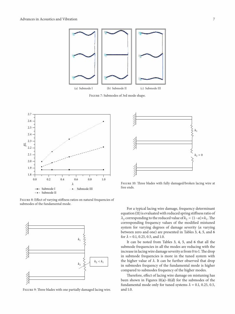
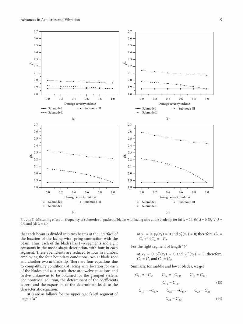
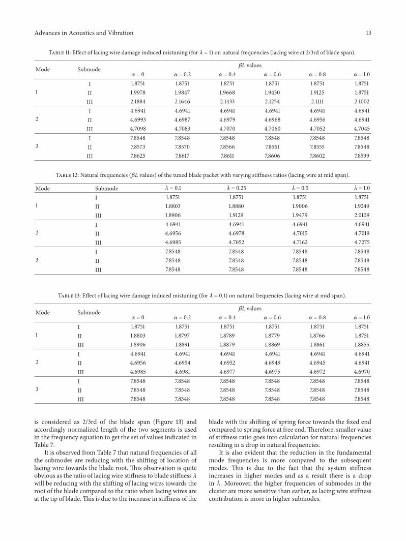
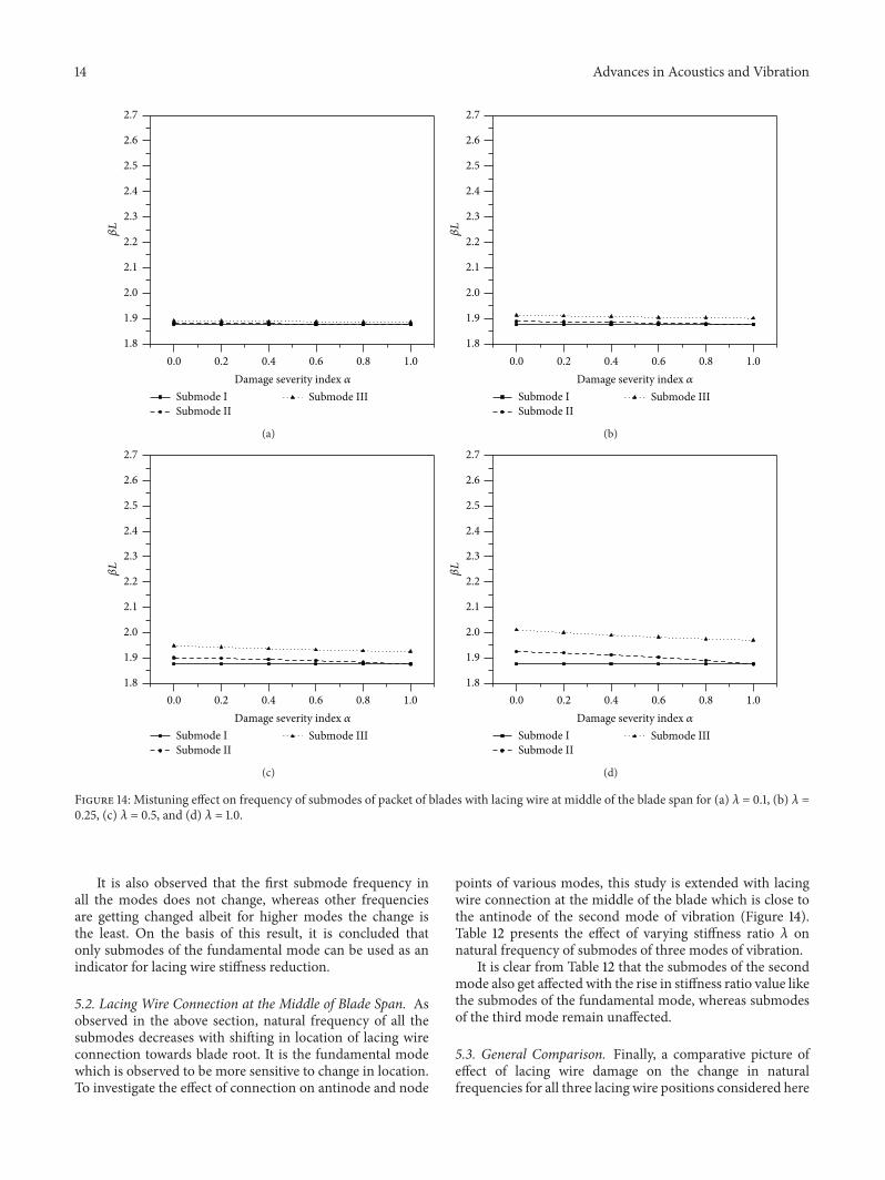

International Journal of
AerospaceEngineeringHindawi Publishing Corporationhttpwwwhindawicom Volume 2014
RoboticsJournal of
Hindawi Publishing Corporationhttpwwwhindawicom Volume 2014
Hindawi Publishing Corporationhttpwwwhindawicom Volume 2014
Active and Passive Electronic Components
Control Scienceand Engineering
Journal of
Hindawi Publishing Corporationhttpwwwhindawicom Volume 2014
International Journal of
RotatingMachinery
Hindawi Publishing Corporationhttpwwwhindawicom Volume 2014
Hindawi Publishing Corporation httpwwwhindawicom
Journal ofEngineeringVolume 2014
Submit your manuscripts athttpwwwhindawicom
VLSI Design
Hindawi Publishing Corporationhttpwwwhindawicom Volume 2014
Hindawi Publishing Corporationhttpwwwhindawicom Volume 2014
Shock and Vibration
Hindawi Publishing Corporationhttpwwwhindawicom Volume 2014
Civil EngineeringAdvances in
Acoustics and VibrationAdvances in
Hindawi Publishing Corporationhttpwwwhindawicom Volume 2014
Hindawi Publishing Corporationhttpwwwhindawicom Volume 2014
Electrical and Computer Engineering
Journal of
Advances inOptoElectronics
Hindawi Publishing Corporation httpwwwhindawicom
Volume 2014
The Scientific World JournalHindawi Publishing Corporation httpwwwhindawicom Volume 2014
SensorsJournal of
Hindawi Publishing Corporationhttpwwwhindawicom Volume 2014
Modelling amp Simulation in EngineeringHindawi Publishing Corporation httpwwwhindawicom Volume 2014
Hindawi Publishing Corporationhttpwwwhindawicom Volume 2014
Chemical EngineeringInternational Journal of Antennas and
Propagation
International Journal of
Hindawi Publishing Corporationhttpwwwhindawicom Volume 2014
Hindawi Publishing Corporationhttpwwwhindawicom Volume 2014
Navigation and Observation
International Journal of
Hindawi Publishing Corporationhttpwwwhindawicom Volume 2014
DistributedSensor Networks
International Journal of
Related Documents