Requirements Engineering: Frameworks for Understanding R.J. Wieringa Faculty of Mathematics and Computer Science Vrije Universiteit Amsterdam c Wiley 1996-2006 c R.J. Wieringa

Welcome message from author
This document is posted to help you gain knowledge. Please leave a comment to let me know what you think about it! Share it to your friends and learn new things together.
Transcript
Requirements Engineering:
Frameworks for Understanding
R.J. Wieringa
Faculty of Mathematics and Computer Science
Vrije Universiteit
Amsterdam
c©Wiley 1996-2006
c©R.J. Wieringa

Contents
1 Introduction 11.1 Computer-based Systems . . . . . . . . . . . . . . . . . . . . . . . . . . . . 11.2 System Development Methods . . . . . . . . . . . . . . . . . . . . . . . . . . 31.3 The Structure of the Book . . . . . . . . . . . . . . . . . . . . . . . . . . . . 41.4 Methods, Techniques, Heuristics . . . . . . . . . . . . . . . . . . . . . . . . 51.5 Bibliographical Remarks . . . . . . . . . . . . . . . . . . . . . . . . . . . . . 6
I An Analysis of Product Development 7
2 Systems 92.1 Introduction . . . . . . . . . . . . . . . . . . . . . . . . . . . . . . . . . . . . 92.2 System Boundary . . . . . . . . . . . . . . . . . . . . . . . . . . . . . . . . . 9
2.2.1 The observability of systems . . . . . . . . . . . . . . . . . . . . . . . 92.2.2 System boundary and modularity . . . . . . . . . . . . . . . . . . . . 12
2.3 System Structure . . . . . . . . . . . . . . . . . . . . . . . . . . . . . . . . . 132.3.1 Subsystems and aspect systems . . . . . . . . . . . . . . . . . . . . . 132.3.2 A hierarchy of system levels . . . . . . . . . . . . . . . . . . . . . . . 14
2.4 System Behavior . . . . . . . . . . . . . . . . . . . . . . . . . . . . . . . . . 162.4.1 System state . . . . . . . . . . . . . . . . . . . . . . . . . . . . . . . 162.4.2 System transactions . . . . . . . . . . . . . . . . . . . . . . . . . . . 172.4.3 System behavior . . . . . . . . . . . . . . . . . . . . . . . . . . . . . 192.4.4 System properties . . . . . . . . . . . . . . . . . . . . . . . . . . . . 20
2.5 System Function . . . . . . . . . . . . . . . . . . . . . . . . . . . . . . . . . 222.5.1 Products . . . . . . . . . . . . . . . . . . . . . . . . . . . . . . . . . 222.5.2 Functions of computer-based systems . . . . . . . . . . . . . . . . . . 23
2.6 The Why, the What and the How . . . . . . . . . . . . . . . . . . . . . . . . 242.7 The Universe of Discourse of Computer-based Systems . . . . . . . . . . . . 262.8 Summary . . . . . . . . . . . . . . . . . . . . . . . . . . . . . . . . . . . . . 272.9 Exercises . . . . . . . . . . . . . . . . . . . . . . . . . . . . . . . . . . . . . 282.10 Bibliographical Remarks . . . . . . . . . . . . . . . . . . . . . . . . . . . . . 30
3 Product Development 333.1 Introduction . . . . . . . . . . . . . . . . . . . . . . . . . . . . . . . . . . . . 333.2 Client-oriented and Market-oriented Development . . . . . . . . . . . . . . . 33
v
vi CONTENTS
3.3 The Product Life Cycle . . . . . . . . . . . . . . . . . . . . . . . . . . . . . 363.3.1 Product development . . . . . . . . . . . . . . . . . . . . . . . . . . 363.3.2 Product implementation . . . . . . . . . . . . . . . . . . . . . . . . . 393.3.3 Product evolution . . . . . . . . . . . . . . . . . . . . . . . . . . . . 403.3.4 The regulatory cycle . . . . . . . . . . . . . . . . . . . . . . . . . . . 41
3.4 Product Engineering . . . . . . . . . . . . . . . . . . . . . . . . . . . . . . . 423.4.1 The engineering cycle . . . . . . . . . . . . . . . . . . . . . . . . . . 423.4.2 Example of an application of the engineering cycle . . . . . . . . . . 45
3.5 System Modeling . . . . . . . . . . . . . . . . . . . . . . . . . . . . . . . . . 483.5.1 Current system modeling and UoD modeling . . . . . . . . . . . . . 483.5.2 The empirical cycle . . . . . . . . . . . . . . . . . . . . . . . . . . . . 493.5.3 Comparison of the empirical and engineering cycles . . . . . . . . . . 52
3.6 A Framework for Product Development Methods . . . . . . . . . . . . . . . 523.6.1 The specification of needs, product behavior and product decomposition 533.6.2 Disentangling requirements and other ambiguities . . . . . . . . . . 563.6.3 Other framework dimensions . . . . . . . . . . . . . . . . . . . . . . 583.6.4 Application of the framework . . . . . . . . . . . . . . . . . . . . . . 60
3.7 Summary . . . . . . . . . . . . . . . . . . . . . . . . . . . . . . . . . . . . . 613.8 Exercises . . . . . . . . . . . . . . . . . . . . . . . . . . . . . . . . . . . . . 623.9 Bibliographical Remarks . . . . . . . . . . . . . . . . . . . . . . . . . . . . . 64
4 Requirements Specifications 714.1 Introduction . . . . . . . . . . . . . . . . . . . . . . . . . . . . . . . . . . . . 714.2 Product Objectives . . . . . . . . . . . . . . . . . . . . . . . . . . . . . . . . 714.3 Behavior and Property Specifications . . . . . . . . . . . . . . . . . . . . . . 734.4 A Framework for Behavior Specifications . . . . . . . . . . . . . . . . . . . . 754.5 Desirable Properties of a Requirements Specification . . . . . . . . . . . . . 764.6 Summary . . . . . . . . . . . . . . . . . . . . . . . . . . . . . . . . . . . . . 784.7 Exercises . . . . . . . . . . . . . . . . . . . . . . . . . . . . . . . . . . . . . 794.8 Bibliographical Remarks . . . . . . . . . . . . . . . . . . . . . . . . . . . . . 79
II Requirements Engineering Methods 81
5 ISAC Change Analysis and Activity Study 835.1 Introduction . . . . . . . . . . . . . . . . . . . . . . . . . . . . . . . . . . . . 835.2 Change Analysis . . . . . . . . . . . . . . . . . . . . . . . . . . . . . . . . . 84
5.2.1 Make a list of problems . . . . . . . . . . . . . . . . . . . . . . . . . 845.2.2 List problem owners . . . . . . . . . . . . . . . . . . . . . . . . . . . 865.2.3 Analyze the problems . . . . . . . . . . . . . . . . . . . . . . . . . . 875.2.4 Make activity model of current business . . . . . . . . . . . . . . . . 915.2.5 Analyze goals . . . . . . . . . . . . . . . . . . . . . . . . . . . . . . . 955.2.6 Define change needs . . . . . . . . . . . . . . . . . . . . . . . . . . . 965.2.7 Generate change alternatives . . . . . . . . . . . . . . . . . . . . . . 975.2.8 Make activity model of desired situations . . . . . . . . . . . . . . . 975.2.9 Evaluate alternatives . . . . . . . . . . . . . . . . . . . . . . . . . . . 985.2.10 Choose an alternative . . . . . . . . . . . . . . . . . . . . . . . . . . 98

CONTENTS vii
5.3 Activity Study . . . . . . . . . . . . . . . . . . . . . . . . . . . . . . . . . . 1005.3.1 Decomposition into information subsystems . . . . . . . . . . . . . . 1005.3.2 Analysis of information subsystems . . . . . . . . . . . . . . . . . . . 1015.3.3 Coordination of information subsystems . . . . . . . . . . . . . . . . 102
5.4 Methodological Analysis . . . . . . . . . . . . . . . . . . . . . . . . . . . . . 1025.4.1 The place of ISAC in the development framework . . . . . . . . . . . 1025.4.2 Activity modeling . . . . . . . . . . . . . . . . . . . . . . . . . . . . 1055.4.3 Participation . . . . . . . . . . . . . . . . . . . . . . . . . . . . . . . 106
5.5 Exercises . . . . . . . . . . . . . . . . . . . . . . . . . . . . . . . . . . . . . 1065.6 Bibliographical Remarks . . . . . . . . . . . . . . . . . . . . . . . . . . . . . 107
6 Information Strategy Planning 1096.1 Introduction . . . . . . . . . . . . . . . . . . . . . . . . . . . . . . . . . . . . 1096.2 The Structure of ISP . . . . . . . . . . . . . . . . . . . . . . . . . . . . . . . 1116.3 Analysis of Business Strategy . . . . . . . . . . . . . . . . . . . . . . . . . . 113
6.3.1 Analyze business mission . . . . . . . . . . . . . . . . . . . . . . . . 1136.3.2 Analyze business goals and objectives . . . . . . . . . . . . . . . . . 1156.3.3 Analyze business problems . . . . . . . . . . . . . . . . . . . . . . . 1166.3.4 Analyze critical success factors . . . . . . . . . . . . . . . . . . . . . 116
6.4 Determination of Information Architecture . . . . . . . . . . . . . . . . . . . 1176.4.1 The function decomposition tree: structure and meaning . . . . . . . 1186.4.2 The function decomposition tree: construction heuristics . . . . . . . 1206.4.3 The entity model: structure and meaning . . . . . . . . . . . . . . . 1226.4.4 The entity model: construction and validation heuristics . . . . . . . 126
6.5 Identification of Business Areas . . . . . . . . . . . . . . . . . . . . . . . . . 1296.6 Methodological Analysis . . . . . . . . . . . . . . . . . . . . . . . . . . . . . 131
6.6.1 The place of Information Engineering in the development framework 1316.6.2 Function decomposition . . . . . . . . . . . . . . . . . . . . . . . . . 1326.6.3 Entity models . . . . . . . . . . . . . . . . . . . . . . . . . . . . . . . 1336.6.4 Information Engineering and ISAC . . . . . . . . . . . . . . . . . . . 134
6.7 Exercises . . . . . . . . . . . . . . . . . . . . . . . . . . . . . . . . . . . . . 1356.8 Bibliographical Remarks . . . . . . . . . . . . . . . . . . . . . . . . . . . . . 136
7 The Entity-Relationship Approach I: Models 1377.1 Introduction . . . . . . . . . . . . . . . . . . . . . . . . . . . . . . . . . . . . 1377.2 Entities, Values and Attributes . . . . . . . . . . . . . . . . . . . . . . . . . 138
7.2.1 ER entities . . . . . . . . . . . . . . . . . . . . . . . . . . . . . . . . 1387.2.2 Attributes . . . . . . . . . . . . . . . . . . . . . . . . . . . . . . . . . 1387.2.3 Values . . . . . . . . . . . . . . . . . . . . . . . . . . . . . . . . . . . 1387.2.4 Null values . . . . . . . . . . . . . . . . . . . . . . . . . . . . . . . . 139
7.3 Types and Existence . . . . . . . . . . . . . . . . . . . . . . . . . . . . . . . 1397.3.1 Intension and extension . . . . . . . . . . . . . . . . . . . . . . . . . 1397.3.2 Representation . . . . . . . . . . . . . . . . . . . . . . . . . . . . . . 1407.3.3 Existence . . . . . . . . . . . . . . . . . . . . . . . . . . . . . . . . . 142
7.4 Entity Identification . . . . . . . . . . . . . . . . . . . . . . . . . . . . . . . 1427.4.1 The importance of identification . . . . . . . . . . . . . . . . . . . . 1427.4.2 Identifiers . . . . . . . . . . . . . . . . . . . . . . . . . . . . . . . . . 143
viii CONTENTS
7.4.3 Surrogates . . . . . . . . . . . . . . . . . . . . . . . . . . . . . . . . . 144
7.4.4 Keys . . . . . . . . . . . . . . . . . . . . . . . . . . . . . . . . . . . . 144
7.5 Relationships . . . . . . . . . . . . . . . . . . . . . . . . . . . . . . . . . . . 145
7.5.1 Identity and existence . . . . . . . . . . . . . . . . . . . . . . . . . . 145
7.5.2 Representations . . . . . . . . . . . . . . . . . . . . . . . . . . . . . . 147
7.6 Cardinality Constraints . . . . . . . . . . . . . . . . . . . . . . . . . . . . . 148
7.6.1 Representations . . . . . . . . . . . . . . . . . . . . . . . . . . . . . . 148
7.6.2 Special cardinalities . . . . . . . . . . . . . . . . . . . . . . . . . . . 150
7.7 The is a Relationship . . . . . . . . . . . . . . . . . . . . . . . . . . . . . . 155
7.8 Methodological Analysis . . . . . . . . . . . . . . . . . . . . . . . . . . . . . 155
7.8.1 The place of ER models in the behavior specification framework . . 155
7.8.2 Cardinality constraints . . . . . . . . . . . . . . . . . . . . . . . . . . 156
7.8.3 Constraints on the UoD and constraints on the system . . . . . . . . 156
7.9 Summary . . . . . . . . . . . . . . . . . . . . . . . . . . . . . . . . . . . . . 157
7.10 Exercises . . . . . . . . . . . . . . . . . . . . . . . . . . . . . . . . . . . . . 158
7.11 Bibliographical Remarks . . . . . . . . . . . . . . . . . . . . . . . . . . . . . 159
8 The Entity-Relationship Approach II: Methods 165
8.1 Introduction . . . . . . . . . . . . . . . . . . . . . . . . . . . . . . . . . . . . 165
8.2 Methods to Find an ER Model . . . . . . . . . . . . . . . . . . . . . . . . . 165
8.2.1 Natural language analysis . . . . . . . . . . . . . . . . . . . . . . . . 167
8.2.2 Natural language analysis of transactions . . . . . . . . . . . . . . . 169
8.2.3 Entity analysis of transactions . . . . . . . . . . . . . . . . . . . . . 170
8.2.4 Case study: the library . . . . . . . . . . . . . . . . . . . . . . . . . 170
8.3 Methods to Evaluate an ER Model . . . . . . . . . . . . . . . . . . . . . . . 177
8.3.1 Entity/value checks . . . . . . . . . . . . . . . . . . . . . . . . . . . 177
8.3.2 Entity/link checks . . . . . . . . . . . . . . . . . . . . . . . . . . . . 179
8.3.3 Specialization check . . . . . . . . . . . . . . . . . . . . . . . . . . . 181
8.3.4 Elementary sentence check . . . . . . . . . . . . . . . . . . . . . . . 182
8.3.5 Population check . . . . . . . . . . . . . . . . . . . . . . . . . . . . . 182
8.3.6 Derivable relationship check . . . . . . . . . . . . . . . . . . . . . . . 183
8.3.7 Minimal arity checks . . . . . . . . . . . . . . . . . . . . . . . . . . . 184
8.3.8 Creation/deletion check . . . . . . . . . . . . . . . . . . . . . . . . . 185
8.3.9 Cross-checking . . . . . . . . . . . . . . . . . . . . . . . . . . . . . . 185
8.3.10 View integration . . . . . . . . . . . . . . . . . . . . . . . . . . . . . 186
8.3.11 Navigation check . . . . . . . . . . . . . . . . . . . . . . . . . . . . 186
8.4 Transformation to a Database System Schema . . . . . . . . . . . . . . . . . 187
8.5 Methodological Analysis . . . . . . . . . . . . . . . . . . . . . . . . . . . . . 189
8.5.1 The place of the ER method in the development framework . . . . . 189
8.5.2 Modeling and engineering . . . . . . . . . . . . . . . . . . . . . . . . 190
8.5.3 Natural language analysis in NIAM . . . . . . . . . . . . . . . . . . 191
8.6 Summary . . . . . . . . . . . . . . . . . . . . . . . . . . . . . . . . . . . . . 192
8.7 Exercises . . . . . . . . . . . . . . . . . . . . . . . . . . . . . . . . . . . . . 192
8.8 Bibliographical Remarks . . . . . . . . . . . . . . . . . . . . . . . . . . . . . 193

CONTENTS ix
9 Structured Analysis I: Models 195
9.1 Introduction . . . . . . . . . . . . . . . . . . . . . . . . . . . . . . . . . . . . 195
9.2 Components of a Data Flow Model . . . . . . . . . . . . . . . . . . . . . . . 195
9.3 Interaction Between the System and its Environment . . . . . . . . . . . . . 197
9.3.1 External entities . . . . . . . . . . . . . . . . . . . . . . . . . . . . . 197
9.3.2 Time and temporal events . . . . . . . . . . . . . . . . . . . . . . . . 199
9.3.3 Event recognition . . . . . . . . . . . . . . . . . . . . . . . . . . . . . 199
9.3.4 Perfect technology . . . . . . . . . . . . . . . . . . . . . . . . . . . . 200
9.4 Data Stores and the ER Diagram . . . . . . . . . . . . . . . . . . . . . . . . 201
9.4.1 Data stores . . . . . . . . . . . . . . . . . . . . . . . . . . . . . . . . 201
9.4.2 The ER diagram . . . . . . . . . . . . . . . . . . . . . . . . . . . . . 202
9.5 Data Flows . . . . . . . . . . . . . . . . . . . . . . . . . . . . . . . . . . . . 206
9.6 Data Transformations . . . . . . . . . . . . . . . . . . . . . . . . . . . . . . 208
9.6.1 Specification by DF diagram . . . . . . . . . . . . . . . . . . . . . . 208
9.6.2 Minispecs . . . . . . . . . . . . . . . . . . . . . . . . . . . . . . . . . 211
9.7 Methodological Analysis . . . . . . . . . . . . . . . . . . . . . . . . . . . . . 214
9.7.1 The place of DF models in the specification framework . . . . . . . . 214
9.7.2 Transactions . . . . . . . . . . . . . . . . . . . . . . . . . . . . . . . 217
9.7.3 Transformation decomposition . . . . . . . . . . . . . . . . . . . . . 218
9.8 Summary . . . . . . . . . . . . . . . . . . . . . . . . . . . . . . . . . . . . . 220
9.9 Exercises . . . . . . . . . . . . . . . . . . . . . . . . . . . . . . . . . . . . . 221
9.10 Bibliographical Remarks . . . . . . . . . . . . . . . . . . . . . . . . . . . . . 222
10 Structured Analysis II: Methods 223
10.1 Introduction . . . . . . . . . . . . . . . . . . . . . . . . . . . . . . . . . . . . 223
10.2 Methods to Find a DF Model . . . . . . . . . . . . . . . . . . . . . . . . . . 223
10.2.1 Essential system modeling . . . . . . . . . . . . . . . . . . . . . . . . 223
10.2.2 Event partitioning . . . . . . . . . . . . . . . . . . . . . . . . . . . . 227
10.2.3 Process analysis of transactions . . . . . . . . . . . . . . . . . . . . . 228
10.2.4 Case study: The Circulation Desk . . . . . . . . . . . . . . . . . . . 229
10.3 Methods to Evaluate a DF Model . . . . . . . . . . . . . . . . . . . . . . . . 236
10.3.1 Walkthroughs and inspections . . . . . . . . . . . . . . . . . . . . . . 236
10.3.2 Simulation and animation . . . . . . . . . . . . . . . . . . . . . . . . 237
10.3.3 Minimality principles . . . . . . . . . . . . . . . . . . . . . . . . . . . 237
10.3.4 Determinism . . . . . . . . . . . . . . . . . . . . . . . . . . . . . . . 239
10.3.5 Vertical balancing . . . . . . . . . . . . . . . . . . . . . . . . . . . . 239
10.3.6 Horizontal balancing and data usage . . . . . . . . . . . . . . . . . . 239
10.4 System Decomposition . . . . . . . . . . . . . . . . . . . . . . . . . . . . . . 240
10.5 Methodological Analysis . . . . . . . . . . . . . . . . . . . . . . . . . . . . . 241
10.5.1 Essential system modeling . . . . . . . . . . . . . . . . . . . . . . . . 241
10.5.2 Event partitioning and data flow orientation . . . . . . . . . . . . . . 243
10.5.3 Specification of user procedures . . . . . . . . . . . . . . . . . . . . . 243
10.6 Summary . . . . . . . . . . . . . . . . . . . . . . . . . . . . . . . . . . . . . 243
10.7 Exercises . . . . . . . . . . . . . . . . . . . . . . . . . . . . . . . . . . . . . 244
10.8 Bibliographical Remarks . . . . . . . . . . . . . . . . . . . . . . . . . . . . . 245
x CONTENTS
11 Jackson System Development I: Models 24711.1 Introduction . . . . . . . . . . . . . . . . . . . . . . . . . . . . . . . . . . . . 247
11.1.1 Jackson Structured Programming . . . . . . . . . . . . . . . . . . . . 24711.1.2 From JSP to JSD . . . . . . . . . . . . . . . . . . . . . . . . . . . . . 249
11.2 The Structure of JSD Models . . . . . . . . . . . . . . . . . . . . . . . . . . 25011.3 The UoD Model . . . . . . . . . . . . . . . . . . . . . . . . . . . . . . . . . 252
11.3.1 JSD entities and attributes . . . . . . . . . . . . . . . . . . . . . . . 25211.3.2 Life cycles . . . . . . . . . . . . . . . . . . . . . . . . . . . . . . . . . 25311.3.3 Parallelism and communication . . . . . . . . . . . . . . . . . . . . . 257
11.4 The System Model . . . . . . . . . . . . . . . . . . . . . . . . . . . . . . . . 26111.4.1 Process communication in the system network . . . . . . . . . . . . 26111.4.2 The specification of function processes . . . . . . . . . . . . . . . . . 267
11.5 Methodological Analysis . . . . . . . . . . . . . . . . . . . . . . . . . . . . . 27111.5.1 The place of JSD models in the behavior specification framework . . 27111.5.2 Transactions . . . . . . . . . . . . . . . . . . . . . . . . . . . . . . . 27111.5.3 Function specification . . . . . . . . . . . . . . . . . . . . . . . . . . 27311.5.4 Entity concepts . . . . . . . . . . . . . . . . . . . . . . . . . . . . . . 27411.5.5 Communication . . . . . . . . . . . . . . . . . . . . . . . . . . . . . . 274
11.6 Summary . . . . . . . . . . . . . . . . . . . . . . . . . . . . . . . . . . . . . 27511.7 Exercises . . . . . . . . . . . . . . . . . . . . . . . . . . . . . . . . . . . . . 27611.8 Bibliographical Remarks . . . . . . . . . . . . . . . . . . . . . . . . . . . . . 276
12 Jackson System Development II: Methods 27912.1 Introduction . . . . . . . . . . . . . . . . . . . . . . . . . . . . . . . . . . . . 27912.2 Case Study: the Document Circulation System . . . . . . . . . . . . . . . . 279
12.2.1 Allocate actions to entity types . . . . . . . . . . . . . . . . . . . . . 28212.2.2 Specify JSD entity types and actions . . . . . . . . . . . . . . . . . . 28512.2.3 Specify life cycle of JSD entities . . . . . . . . . . . . . . . . . . . . 28612.2.4 Specify action effects . . . . . . . . . . . . . . . . . . . . . . . . . . . 28612.2.5 Context errors . . . . . . . . . . . . . . . . . . . . . . . . . . . . . . 29012.2.6 System functions . . . . . . . . . . . . . . . . . . . . . . . . . . . . . 290
12.3 Evaluation Methods for UoD Models . . . . . . . . . . . . . . . . . . . . . . 29412.4 Implementation . . . . . . . . . . . . . . . . . . . . . . . . . . . . . . . . . . 29412.5 Methodological Analysis . . . . . . . . . . . . . . . . . . . . . . . . . . . . . 294
12.5.1 Separation of UoD modeling from function specification . . . . . . . 29412.5.2 JSD and Information Engineering . . . . . . . . . . . . . . . . . . . 29512.5.3 JSD and structured development . . . . . . . . . . . . . . . . . . . . 29512.5.4 Modeling social processes . . . . . . . . . . . . . . . . . . . . . . . . 296
12.6 Summary . . . . . . . . . . . . . . . . . . . . . . . . . . . . . . . . . . . . . 29612.7 Exercises . . . . . . . . . . . . . . . . . . . . . . . . . . . . . . . . . . . . . 29712.8 Bibliographical Remarks . . . . . . . . . . . . . . . . . . . . . . . . . . . . . 297
III Method Integration and Strategy Selection 299
13 A Framework for Requirements Engineering I: Models 30113.1 Introduction . . . . . . . . . . . . . . . . . . . . . . . . . . . . . . . . . . . . 301
CONTENTS xi
13.2 The Specification of Product Objectives . . . . . . . . . . . . . . . . . . . . 30113.3 A Framework for Behavior Specifications . . . . . . . . . . . . . . . . . . . . 305
13.3.1 UoD models . . . . . . . . . . . . . . . . . . . . . . . . . . . . . . . . 30513.3.2 Models of system behavior . . . . . . . . . . . . . . . . . . . . . . . . 30713.3.3 Relationship between UoD models and SuD models . . . . . . . . . 309
13.4 Integrated JSD-ER Models of the UoD . . . . . . . . . . . . . . . . . . . . . 30913.4.1 Entities . . . . . . . . . . . . . . . . . . . . . . . . . . . . . . . . . . 31213.4.2 Using relationships to remember common actions . . . . . . . . . . . 31213.4.3 Reducing common actions by adding relationships . . . . . . . . . . 31313.4.4 The transaction decomposition table . . . . . . . . . . . . . . . . . . 314
13.5 Integrated JSD-ER-DF Models of a System . . . . . . . . . . . . . . . . . . 31513.5.1 A JSD-ER-DF initial system model . . . . . . . . . . . . . . . . . . 31513.5.2 A JSD-ER-DF model of system functions . . . . . . . . . . . . . . . 31613.5.3 The transaction decomposition table . . . . . . . . . . . . . . . . . . 320
13.6 Modularization Principles . . . . . . . . . . . . . . . . . . . . . . . . . . . . 32213.6.1 Object-oriented and Von Neumann modularization . . . . . . . . . . 32213.6.2 UoD-oriented modularization . . . . . . . . . . . . . . . . . . . . . . 323
13.7 Integrating System Models with Environment Models . . . . . . . . . . . . 32613.8 Summary . . . . . . . . . . . . . . . . . . . . . . . . . . . . . . . . . . . . . 32713.9 Exercises . . . . . . . . . . . . . . . . . . . . . . . . . . . . . . . . . . . . . 32813.10Bibliographical Remarks . . . . . . . . . . . . . . . . . . . . . . . . . . . . . 328
14 A Framework for Requirements Engineering II: Methods 33314.1 Introduction . . . . . . . . . . . . . . . . . . . . . . . . . . . . . . . . . . . . 33314.2 Starting Points . . . . . . . . . . . . . . . . . . . . . . . . . . . . . . . . . . 33514.3 Finding a Behavior Specification . . . . . . . . . . . . . . . . . . . . . . . . 33614.4 Evaluating a Behavior Specification . . . . . . . . . . . . . . . . . . . . . . . 33814.5 Requirements Engineering as Negotiation about Meanings . . . . . . . . . . 340
14.5.1 Negotiation in discovery and engineering . . . . . . . . . . . . . . . . 34014.5.2 Implicit conceptual models and the ultimate communication breakdown341
14.6 Summary . . . . . . . . . . . . . . . . . . . . . . . . . . . . . . . . . . . . . 34414.7 Exercises . . . . . . . . . . . . . . . . . . . . . . . . . . . . . . . . . . . . . 34414.8 Bibliographical Remarks . . . . . . . . . . . . . . . . . . . . . . . . . . . . . 345
15 Development Strategies 34715.1 Introduction . . . . . . . . . . . . . . . . . . . . . . . . . . . . . . . . . . . . 34715.2 Process Management . . . . . . . . . . . . . . . . . . . . . . . . . . . . . . . 34815.3 Top-down Development Strategies . . . . . . . . . . . . . . . . . . . . . . . 351
15.3.1 The linear strategy . . . . . . . . . . . . . . . . . . . . . . . . . . . . 35215.3.2 The splashing waterfall strategy . . . . . . . . . . . . . . . . . . . . 35415.3.3 The V-strategy . . . . . . . . . . . . . . . . . . . . . . . . . . . . . . 354
15.4 A Framework for Concurrent Development . . . . . . . . . . . . . . . . . . . 35815.5 Throw-away Prototyping . . . . . . . . . . . . . . . . . . . . . . . . . . . . . 36215.6 Strategies for Phased Development . . . . . . . . . . . . . . . . . . . . . . . 363
15.6.1 Incremental development . . . . . . . . . . . . . . . . . . . . . . . . 36415.6.2 Evolutionary development . . . . . . . . . . . . . . . . . . . . . . . . 36515.6.3 Experimental development . . . . . . . . . . . . . . . . . . . . . . . 366

xii CONTENTS
15.7 Rational Reconstruction of the Development Process . . . . . . . . . . . . . 36815.8 Summary . . . . . . . . . . . . . . . . . . . . . . . . . . . . . . . . . . . . . 36915.9 Exercises . . . . . . . . . . . . . . . . . . . . . . . . . . . . . . . . . . . . . 37015.10Bibliographical Remarks . . . . . . . . . . . . . . . . . . . . . . . . . . . . . 371
16 Selecting a Development Strategy 37716.1 Introduction . . . . . . . . . . . . . . . . . . . . . . . . . . . . . . . . . . . . 37716.2 The Spiral Model for Software Development . . . . . . . . . . . . . . . . . . 377
16.2.1 Structure . . . . . . . . . . . . . . . . . . . . . . . . . . . . . . . . . 37716.2.2 Strategies . . . . . . . . . . . . . . . . . . . . . . . . . . . . . . . . . 37916.2.3 Strategy selection heuristics . . . . . . . . . . . . . . . . . . . . . . . 38016.2.4 Evaluation of the spiral model . . . . . . . . . . . . . . . . . . . . . 382
16.3 Euromethod . . . . . . . . . . . . . . . . . . . . . . . . . . . . . . . . . . . . 38316.3.1 Structure . . . . . . . . . . . . . . . . . . . . . . . . . . . . . . . . . 38316.3.2 Strategies . . . . . . . . . . . . . . . . . . . . . . . . . . . . . . . . . 38616.3.3 Situational factors . . . . . . . . . . . . . . . . . . . . . . . . . . . . 38716.3.4 Strategy selection heuristics . . . . . . . . . . . . . . . . . . . . . . . 38816.3.5 Evaluation of Euromethod . . . . . . . . . . . . . . . . . . . . . . . . 394
16.4 Summary . . . . . . . . . . . . . . . . . . . . . . . . . . . . . . . . . . . . . 39416.5 Exercises . . . . . . . . . . . . . . . . . . . . . . . . . . . . . . . . . . . . . 39516.6 Bibliographical Remarks . . . . . . . . . . . . . . . . . . . . . . . . . . . . . 395
A Answers to Selected Exercises 397
B Cases 415B.1 The Teaching Administration . . . . . . . . . . . . . . . . . . . . . . . . . . 415B.2 The University Library . . . . . . . . . . . . . . . . . . . . . . . . . . . . . . 415
C An outline of some development methods 419C.1 ETHICS . . . . . . . . . . . . . . . . . . . . . . . . . . . . . . . . . . . . . . 419C.2 Structured Development . . . . . . . . . . . . . . . . . . . . . . . . . . . . . 421C.3 SSADM . . . . . . . . . . . . . . . . . . . . . . . . . . . . . . . . . . . . . . 421
Bibliography 426
Index 444
Preface
This book is about methods for determining computer system requirements. It is writtenprimarily as an introduction to requirements engineering methods for computer science stu-dents, but the text has been organized in such a way that it can also be used by practitionerswho want to place their work in a wider context.
Over the past 30 years, a jungle of methods and techniques has grown that can be usedat different stages of development, from requirements determination to implementation andmaintenance. This jungle is ill-structured in appearance, and students as well as practi-tioners are at a loss where to look for useful methodological advice. One may wonder ifit is worthwhile to hack the methodological jungle at all. The goal of the book is to showthat there is a structure in this jungle. The book starts in part I with the definition of amethodological framework that can be used to compare methods. In part II it then analyzesfive methods for requirements determination, using this framework, and it ends in part IIIby collecting the results of these analyses into an integrated framework for requirementsengineering methods. The text has the following features.
• Several frameworks for methods are defined. In part I, frameworks for system deve-lopment and for requirements specifications are defined. In part III, the developmentframework is extended to a framework for development strategies.
• The development of computer-based systems is viewed as a species of industrial prod-uct development. Consequently, the frameworks are borrowed partly from the method-ology of industrial product development.
• An engineering approach to system development is emphasized. Features of such anapproach are the separation of specification from implementation, rational search foralternatives, and simulation of a solution before implementing it.
• The book focuses on methods for requirements engineering. These methods bridge theoften informal world of human desires with the formal world of symbol manipulation.Mistakes are easily made in this task, it is hard to discover them, and the later theyare discovered, the harder it is to repair them.
• The chapters on the five methods are written for computer science students withoutany knowledge of development methods. They present methods to the level of detailneeded to do practical work with them, without getting buried in a mass of syntacticdetails. The chapters include two running case studies and each chapter finishes withexercises. Appendix A contains answers to selected exercises.
xiii
xiv PREFACE
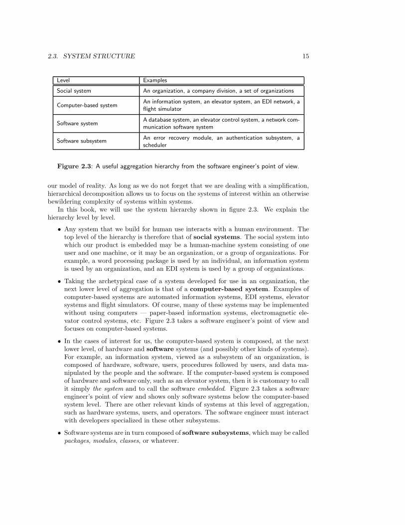
7, 8: Entity-Relationship Modeling9, 10: Structured Analysis
The core
5: Change Analysis6: Information Strategy Planning
The business context
2: Systems3: Product Development4: Requirements Specification
The methodological context
13: Model Integration14: Method Integration
Method comparison
15: Development Strategies16: Strategy Selection
The development process
11, 12: JSD
Life cycle modeling
Part I
Part II
Part III
PREFACE xv
• There is an index containing all keywords and defined terms. The number of the pagewhere a term is defined, is printed in boldface.
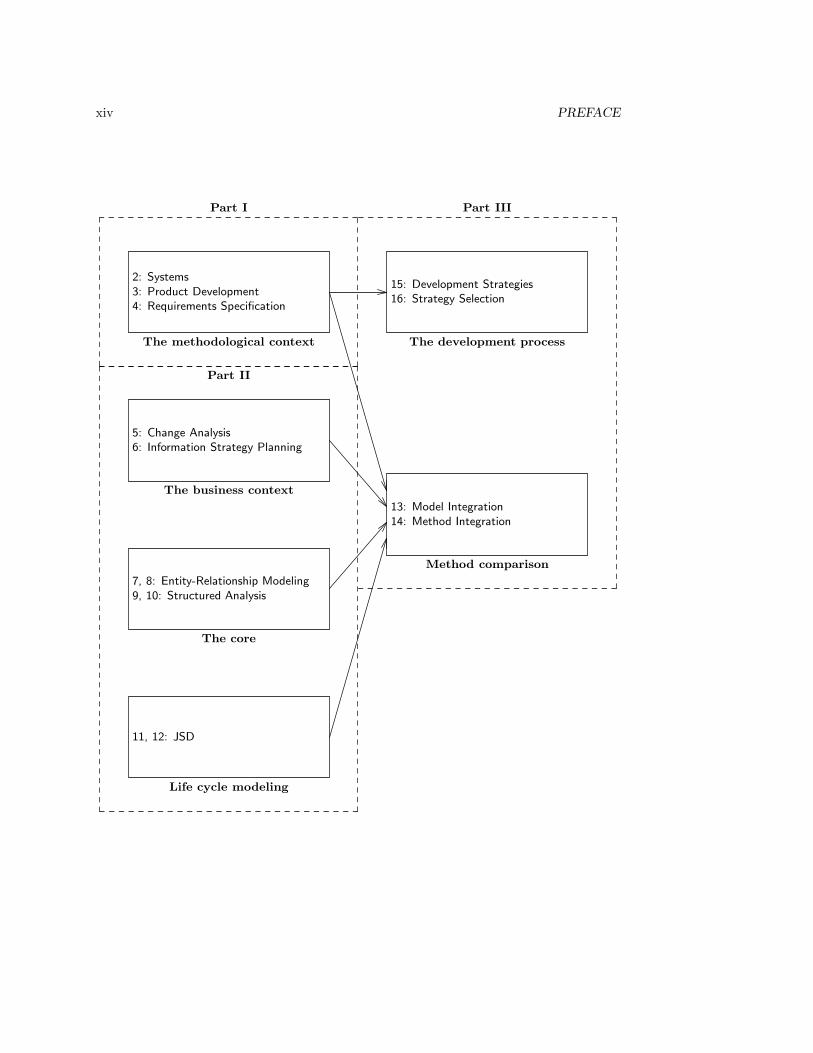
• As indicated in the figure, the substance of the chapters on the five methods can beread without knowing about the methodological frameworks of part I. The chaptersare structured according to these frameworks, but it is not necessary to know theseframeworks in order to read the chapters.
• Each chapter about a method ends with a methodological analysis of the method thatpresupposes the methodological frameworks of part I. This methodological discussionculminates in part III with an indication where and how the discussed methods canbe integrated.
• The choice of methods has been very conservative. The methods included in part II areeither widely used or they illustrate an interesting methodological point. One premiseof this book is that every method contains at least one good idea and that there isno method that contains only good ideas. The approach has been to emphasize thegood ideas. For reasons of space, only a fragment of some methods is explained.
It should be clear that this book advocates an eclectic approach to methods. The frame-works defined in this book can be viewed as empty toolboxes, to be filled with tools takenfrom different methods. These tools are conceptual. Their user should understand theirpossibilities and limitations, and should know which ones can be combined and which aremutually exclusive alternatives. It is one of the hallmarks of the engineer that he or shekeeps an open mind about possibilities and does not choose a particular design too soon.This also applies to the choice of tools: even tools that have been invented long ago andare regarded as “outdated” may be useful.
Object-oriented methods are conspicuously absent from this book. The reason for thisis that in order to achieve progress in the field of methods, we should understand andconsolidate older methods before we advance to newer methods. A sequence of revolutionsin which every revolution obliterates all memory of what has gone before, does not constituteprogress. The book accordingly tries to consolidate the good ideas in structured methods.A companion volume currently in preparation (Requirements Engineering: Semantic, Real-Time and Object-Oriented Methods), uses the frameworks developed in this book to analyzeadvanced requirements modeling methods.
Chapters 1 through 14 and the practical work that goes with it can be covered in a one-semester course of 5 credit points (5 full-time weeks of student work) that includes practicalwork. Chapters 15 and 16 complete the methodological analysis begun in chapter 3 andcan be reserved for a consolidation of these ideas in a follow-up course on process issues.
To understand methods, one should practice them. The chapters on the five methodsshould be accompanied with laboratory work in which students do case studies with thesemethods. A workbench that can be used to draw the diagrams of the different methodsis available for academic and research purposes without fee at ftp site ftp.cs.vu.nl indirectory pub/tcm. The workbench runs on Unix systems. For precise system requirements,refer to the file README.TCM.
As illustrated in the figure, the book has been structured in such a way that teacherscan choose to omit some chapters.

xvi PREFACE
• After the introductory chapter, chapters 7 to 10 form an introduction to the classicalcore of requirements specification, viz. ER modeling and Structured Analysis.
• To embed the core in its methodological context, part I can be used to discuss(software) product development and the framework for development methods usedin this book. Each method chapter in part II ends with a methodological analysis,that presupposes knowledge of part I. By skipping these methodological analyses, themethods of part II can be treated without treating part I first.
• To explain the relation between requirements specification and the business context,the core can be extended with chapters 5 and 6 on Change Analysis and InformationStrategy Planning.
• Jointly, chapters 1 to 10 give a fairly standard introduction to requirements specifica-tion. Chapters 11 to 14 treat JSD and method integration. These chapters are moredifficult and can be used as part of an optional, more advanced course that focuseson life cycle modeling and on method comparison.
• Chapters 15 and 16 discuss strategies for the development process and can be usedin any course that has covered part I of the book.
Parts of chapter 13 have been published in the Computer Journal, volume 38, number 1,by Oxford University Press. Thanks are due to five generations of students who, everyyear, patiently plodded through a version of this manuscript and took everything seriouslythat was written in it. Their problems with the text have taught me a lot. This bookcontains some of the fruits of many stimulating and enjoyable discussions with John-JulesMeyer, Frank Dignum and Hans Weigand about the formalization of system constraints, andwith Wiebren de Jonge about the methodology of entity classification and identification.The book also benefited from discussions with and critical comments from Frank Dehne,Marcel Franckson, Remco Feenstra, Hanna Luden, Gunter Saake, Jeroen Scheerder andJohn Simons. Gaynor Redvers-Mutton of John Wiley & Sons, Inc. showed me how torephrase my prose as natural language. Ameen Abu-Hanna provided some stimulating anduseful comments on the first chapters of the book. Jan Broersen read the entire manuscriptand prevented many typos and errors from going into print. Any remaining errors are tobe blamed upon me.
Writing this book has been made bearable by the unseizing efforts of Mieke Poelmanwho, despite a busy career of her own, managed to find the time to keep me from my work.Her unconditional support has given me both the freedom and the strength to finish thisproject. I dedicate this book to her.
Bilthoven and Amsterdam, December 1995RJW

Chapter 1
Introduction
1.1 Computer-based Systems
This book is about methods to specify requirements for computer-based systems. To fo-cus thoughts, it is useful to identify three groups of computer-based systems: automatedinformation systems, communication systems and control systems. These groups are notdisjoint, but each group has particular characteristics. In this section, I give a number ofexamples of systems in each group and in the next, we turn to methods to develop thesesystems.
The characterizing feature of computer-based information systems is that they storeand manipulate large amounts of data.
• A system that registers the current store of items held by an outlet of a supermarketchain is an information system. For each kind of item sold by the outlet, the informa-tion system contains, say, a record containing information about the price, the numberof items still in store, the supplier of the item, etc. These records are updated whengoods are delivered and when the goods are moved from the store to the shop. Thesystem may be connected to point-of-sale terminals with bar code readers, that readthe kind and number of products when they are sold and transmit this informationto the information system.
• A reservation system for airline tickets is an information system. The system maybe distributed over many different travel agencies, that all have concurrent access tothe services of the system in real time. The business transactions processed by thereservation system are reservations of flights made by air transport companies.
• A system that helps managers to analyze market trends and to predict possible effectsof changes in strategy or of different ways to implement a chosen strategy is an infor-mation system. The system collects data from corporate databases, summarizes thisinto aggregate data, plots trends, and uses econometric models to compute alternativefuture scenarios.
The point-of-sale system and the reservation system are called transaction processing sys-tems, because their main function consists in registering or performing business transactions.
1
2 CHAPTER 1. INTRODUCTION
The management support system is an example of a decision support system, because itsupports management in making strategic decisions. If these systems are used by seniorexecutives, they are also called executive information system. In this book, we view all ofthese systems as examples of information systems.
The characteristic feature of communication systems is that they involve heavy com-munication traffic between nodes that are located at geographically different places. As canbe seen from the examples above, some information systems can be classified as communi-cation systems as well. Other examples of communication systems include the following.
• An electronic data interchange system (EDI system) is a system that connects infor-mation systems of different companies with each other. The EDI system can be set upin such a way that the information systems of all outlets of a supermarket chain canbe connected, through an EDI network, with the order processing system of a supplierof dairy products. For example, every Friday before noon, the information systems inthe supermarket chain outlets determine the current stock of dairy products, computeor retrieve the expected buying pattern for the next week, and place an order for dairyproducts at the supplier over the EDI network, to be delivered on Monday morning.
• The INTIS network in the port of Rotterdam connects information systems of trans-port companies, shipping agents, docks, ship brokers, insurance companies, the Dutchpostal services and customs. Movement of goods into and out of the harbor is accom-panied by an exchange of messages over this network, that replaces a labor-intensiveand error-prone flow of manually written documents.
• Weapons systems typically involve intensive communication between a command cen-ter, ground stations, satellites, and remote systems such as aircraft, in a highly dis-tributed environment in which systems must respond in real time.
The characteristic feature of control systems is that they respond to events in theirenvironment by sending control messages to the environment. Some communication systemsmay be classified as control systems as well. Usually, control systems have interfaces tohardware other than computers, they control the behavior of some of this hardware, theymust function in real time and there are strict limits on the response time of the system.For this reason, control systems are also called real-time systems or embedded systems. Wewill not use these terms, for any system must operate in real time and is embedded inan environment. For example, most administrative systems must perform certain actionsbefore certain hard deadlines, such as the end of the month (salary payment) or the end ofthe year (financial reporting). All information and communication systems are embeddedin a social system, and many must communicate with hardware, just as control systems do.Examples of control systems include the following.
• A computer-based system that controls the barriers at the gate of a parking garageis a control system. The system must be able to sense that a car wants to enter thebuilding, check that the car has permission, raise the barrier, sense that the car haspassed and lower the barrier before another car can enter. The system must monitorthe number of cars in the building and refuse entry of a car as long as the building isfull.
• Another example is an elevator control system that monitors requests for elevatorservice and directs the elevator cage to the appropriate floors.
1.2. SYSTEM DEVELOPMENT METHODS 3
• A computer integrated manufacturing control system that monitors the movement ofmaterial through a number of machines is an example of a control system.
Having given an idea of the kind of systems that we are interested in, we now turn to thetopic of the book, methods to develop these systems.
1.2 System Development Methods
Since, at the end of the 1960s, the idea arose that computer-based systems must be de-veloped in a methodical way, the field of system development methods has been in a stateof flux. In the 1960s, system development was mainly concerned with implementation,viewed narrowly as programming. Wider issues such as requirements analysis and systemspecification were ignored. In the 1970s, a number of methods were introduced that inone way or another left the computer programming level and took these wider issues intoaccount. Several methods for structured analysis and requirements specification came intobeing, culminating in methods for the structured specification of real-time systems in themid-1980s. In parallel to this, methods were proposed to specify the meaning of data, suchas entity-relationship modeling and these evolved into so-called semantic modeling meth-ods in the early 1980s. By the end of the 1980s, the structured and semantic approacheswere followed by an ever growing crop of object-oriented analysis and design methods.The bibliographical remarks in section 1.5 lists references to 26 methods for requirementsspecification, illustrative for each of the groups just mentioned: structured, semantic andobject-oriented methods. This is not an exhaustive list: the actual number of methods inuse by practitioners or proposed by researchers runs in the hundreds, if not thousands, ifcounted world-wide. Clearly, this multitude of methods poses problems for the novice aswell as for the experienced practitioner.
• A problem for the novice is that it is not clear which of these methods one shouldlearn, if any. Do the new, object-oriented (OO) methods make other methods obso-lete? Can we save time by ignoring the older methods and limit our reading only tothe object-oriented methods? Is it possible to understand object-oriented methodswithout knowing anything about the older methods? Conversely, is it possible tounderstand current practice after having read only about object-oriented methods?
• The practitioner too wonders what the relation between new object-oriented methodsand the older structured ones is. How can methods be evaluated on their effectivenessand efficiency in developing the system that the user really wants? Supposing it isworthwhile to move to a new method, how can this transition best be accomplished?Which method is “best”, according to a set of criteria chosen by management, for agiven development project? Is there a way in which a customized method can be builtfor a development project, using components from existing methods?
These questions revolve around the underlying problem of what the relationships betweenthe different methods — new and old — are. It is the aim of this book to provide analyticframeworks with which to understand current and future methods, and to apply theseframeworks to a number of important current methods.
4 CHAPTER 1. INTRODUCTION
1.3 The Structure of the Book
Although some of the frameworks given in this book apply to the entire development pro-cess, we focus on methods for requirements specification. The reason for this is that require-ments specification is an identifiable and important activity within system development.Requirements specification is an identifiable activity for which many methods have beenproposed. Indeed, it is arguable that all development methods listed in section 1.2 dealwith requirements at some level of aggregation, and ignore other important topics like sys-tem decomposition, integration and testing. The focus on requirements specification can bejustified because errors made in requirements become increasingly costly to repair the laterwe are in development, and are extremely costly to repair after delivery of the system — ifthey can be repaired at all in that stage.
In order to understand requirements specification methods, we look in part I at the widercontext of product development. In chapter 2, we define systems as parts of the world thathave an observable behavior and an internal structure, and products as artificial systemsconstructed to provide a function to users. In chapter 3, we look at product development,the product life cycle, product evolution and product engineering. Chapter 3 ends withthe definition of a framework for product development methods, which allows us to identifythe place of requirements specification in product development. The framework also showswhat the logical structure of the requirements specification activity is. In chapter 4 we focuson the result of the requirements specification process, and give a framework that tells uswhat the logical structure of requirements specifications is. The two frameworks are usedin part II to analyze five methods for requirements specification.
• In chapter 5, we look at Change Analysis and Activity Study, which are part of theISAC method for developing information systems.
• In chapter 6, we look at Information Strategy Planning (ISP), which is part of Infor-mation Engineering.
• In chapters 7 and 8, we look at the Entity-Relationship (ER) method and at thestructure of the specifications produced by this method.
• In chapters 9 and 10, we look at Structured Analysis (SA) and at the structure of thespecifications produced by this method.
• In chapters 11 and 12, we look at a part of the Jackson System Development (JSD)method and at the structure of the specifications produced by this method.
In part III, we gather the results of our analyses and fill out the two frameworks. In chap-ter 13, we compare the structure of software requirements specifications produced by ERmodeling, SA, and JSD by placing them in the framework developed in chapter 4. In chap-ter 14, we summarize the results about finding and evaluating requirements specificationsby placing them in the framework developed in chapter 3.
The focus of the two frameworks is on the logical structure of requirements specificationsand of methods to find and evaluate such specifications. In chapters 15 and 16 we extendour framework to incorporate the temporal dimension. This allows us to define alternativedevelopment strategies in chapter 15. These are all compatible with the logical frameworkfor development defined in chapter 3, but choose different paths through the logical tasks.
1.4. METHODS, TECHNIQUES, HEURISTICS 5
In chapter 16, we conclude the book by discussing the spiral method and Euromethod asways to select an appropriate strategy for a particular development process.
1.4 Methods, Techniques, Heuristics, Notations and Me-thodologies
As can be seen from the short overview above, a major element in the approach of this bookis the distinction between methods and methodology. Part II of this book is a descriptionof methods, parts I and III contain a methodological analysis of methods. In this section,we define some terms that are used throughout the book.
A method is a systematic way of working by which one can obtain a desired result. Thedesired result may be the specification of a more cost-effective way of operating a business,a specification of product requirements, a specification of the decomposition of a system, aspecification of a marketing plan, a specification of a production process, an implementedproduct, an installed product, etc.
A technique is a recipe for obtaining a certain result. Since a recipe is a systematicway to obtain a certain result, all techniques are methods. However, not all methods aretechniques. Usually, techniques prescribe a way of working in detail, whereas methods neednot contain detailed instructions. There are techniques to serve a volleyball, to performa dance, to bake a pancake, and to write a structured program. Many methods containtechniques to perform particular tasks. Examples of techniques treated in this book are thediagonalization technique of Information Engineering and the technique of transformingan ER model into a relational database schema. Techniques can often be practiced toperfection and in many cases can be automated. When applied to the right problem in theright context, they are guaranteed to deliver the desired result. However, applied outsidetheir proper context, they lead to garbage.
Most methods additionally provide heuristics to help the developer find or evaluate asystem specification. A heuristic is a problem-solving advice that has proved to lead toa good solution in many cases. Application of a heuristic is not guaranteed to lead to thedesired result. Heuristics given by Polya [263] to solve mathematics problems are to look atrelated problems, to try a more accessible related problem first, to go back to definitions,etc. Examples of heuristics to find a system specification are to analyze natural languagedescriptions of system behavior, to look at possible use scenarios, to list the events to whichthe system must respond, etc.
A notation is a systematic way to represent something. Notations may be linguistic,consisting of textual symbols, or graphical, consisting of diagrams. All methods discussedin this book use diagrams as part of their notation to represent a system. Examples areER diagrams, data flow diagrams, Jackson process structure diagrams, etc. Most methodssupplement the diagram notation with textual notation, in the form of a data dictionary,annotations to diagrams, narrative text, etc.
Methodology is the study of methods. For example, the methodology of empiricalscience is the study of methods used to discover laws of nature; the methodology of math-ematics is the study of methods used to find and prove mathematical truths; and themethodology of engineering is the study of methods used to produce useful artifacts. Thisbook is an example of engineering methodology, in particular of the methodology of buildingcomputer-based systems.
6 CHAPTER 1. INTRODUCTION
1.5 Bibliographical Remarks
Computer-based systems. The engineering of computer-based systems (ECBS) wasthe subject of a workshop held in Neve-Ilan, Israel in May 1990 [189]. This workshop led tothe institution of an IEEE Computer Society task force on ECBS [360], which summarizedthe state of the practice in this area and identified topics for research. In Europe, theATMOSPHERE project was launched in 1990, partly funded as an Esprit II technologyintegration project [245]. Its aim was to contribute to the state of the art in the engineeringof computer-based systems. An overview of methodological results of the ATMOSPHEREproject is given by Thome [345].
Introductions to particular kinds of computer-based systems are Davis and Olson [82]and Kendall and Kendall [174] for information systems, and Keen and Scott Morton [171]for decision support systems. Good introductions to control systems are given by Ward andMellor [354, 355, 227], Hatley and Pirbhay [141] and by Goldsmith [118]. These referencesinclude some discussion of distribution and communication aspects.
System development methods. Examples of information system development meth-ods developed in the 1970s and 1980s are ISAC [204], SSADM [14, 91], Information Engi-neering [217], ETHICS [235] and Multiview [16], which is built from components of othermethods. Examples of conceptual modeling methods that have their roots in the 1970s areER modeling [65], Structured Analysis [84, 108] and SADT [210]. Two methods withtheir roots in the 1970s, but which were published in the 1980s, are NIAM [244] andJSD [57, 56, 158]. Another development in the 1980s is the advent of semantic modelingmethods, such as the Event Model [179, 180], SDM [135], TAXIS [46], and ACM/PCM [52].Important methods for the development of control systems (real time and embedded) arethe Ward-Mellor extension of SA [354, 355, 227] and the Hatley-Pirbhai extension [141].Goldsmith [118] develops the Ward-Mellor method further and Shumate and Keller [313]integrate the Hatley-Pirbhai method with elements of the Ward-Mellor method. Gomaadeveloped a family of structured methods for control systems called DARTS, ADARTS andCODARTS [119, 120, 122]. These methods contain useful advice on structuring criteriafor control systems. Examples of methods composed of elements of other methods areInformation Engineering [213], SSADM [14, 91, 98], and Multiview [16].
In the 1990s, object-oriented methods became the focus of interest. Examples are theBooch method [45], OMT [296], the Shlaer-Mellor method [308, 309], the Coad-Yourdon [68,377], the Martin-Odell [218], Objectory [163] and the ROOM method [307]. The FUSIONmethod [71] is built from components of other methods, notably OMT and some elements offormal specification. An important part of research in object-oriented methods is concernedwith the question whether object-oriented methods can be integrated with older, well-knownmethods like SA and ER modeling and whether semantic modeling can be made part ofobject-oriented modeling [6, 19, 304, 353, 363].
Part I
An Analysis of ProductDevelopment
7


Chapter 2
Systems
2.1 Introduction
The concept of a system is a crucial tool in understanding system development methods.Unfortunately, different authors use different definitions of this concept. Some view a systemas an organized collection of components, others view the concept of a state space as centralto the system concept and still others take purposive behavior as the defining characteristicof a system. In section 2.2, we start from a minimal concept of a system that is common to alldifferent approaches, viz. that of a system as an observable part of the world. In section 2.3,we introduce the familiar concept of a system as an organized collection of related elements.In section 2.4, we add the perspective of observable system behavior, which allows us todefine the important concept of state space. In section 2.5, we look at systems from theperspective of their function for their environment, which allows us to introduce the conceptof system objective. This falls short of the idea of purposive behavior mentioned above,but it suffices for our purpose. The distinctions between function, behavior and structureare summarized in section 2.6. In section 2.7, we look at a concept that is characteristic fordata-manipulating systems such as computers, the universe of discourse.
2.2 System Boundary
2.2.1 The observability of systems
It is possible to speak of the system of natural numbers, a system of law, a software system,a system of logical inference rules and the solar system. For our purpose, a system conceptthat would encompass all these different uses of the word “system” would be too general tobe useful. We will therefore restrict the use of the term to observable systems, where theconcept of observation is left unexplained. If pressed for an explanation, I would say that anobservation is always an interaction of a system with its environment, where the interactionmay be initiated by the system or by its environment. Conversely, any interaction of asystem with its environment is viewed in this book as an observation of the system by itsenvironment. (Depending upon one’s point of view, it can also be viewed as an observationof the environment by the system). This reduces one unexplained concept (observation) to
9
10 CHAPTER 2. SYSTEMS
another (interaction) and vice versa. Perhaps this is typical for starting points.
In what follows, I treat observation as synonymous with interaction between systems.To make the situation more vivid, I will often treat the environment of a system as anobserver who observes the system by interacting with it. Each interaction can be viewed asan experiment in which the observer learns something about the system.
Given this, a system is defined as any actual or possible part of reality that, if itexists, can be observed. We illustrate this definition with some examples, non-examplesand borderline cases of systems:
• Physical objects like cars, stones, trees, elevators and airplanes are systems. Observa-tions of these systems include observations of their color, weight, speed, and location.To make observations, we perform an interaction with the system, and when we in-teract with these systems, we make observations.
• Intangible objects like operating systems, database management systems, informationsystems and organizations are systems. From the point of view of physics, theseobjects are not observable. Nevertheless, they can interact with other systems andfrom our point of view therefore, they are observable. If we were to restrict ourselvesto observations allowed in physics, organizations would be invisible, but since we allowobservations allowed in social science and psychology, organizations are observable.Observations of these systems include observations of responses to commands, queries,requests, statements, of the time it takes to produce these responses, of resource usageduring the production of the responses, etc.
• Abstract entities like numbers, truth values and letters are not systems. The number3 cannot interact with other numbers or with anything else. It does stand in mathe-matical relations to other numbers, but this is different from engaging in interactionswith those numbers. The mathematical relations are not events occurring in time.Similarly, the letter denoted by the symbol “a” cannot interact with other systems.By contrast, a symbol that represents the number 3 or the letter “a” can interact withother systems. It can be written, read and erased, for example.
• The “system” of Peano axioms for the natural numbers is not a system in our sense,for it cannot interact with other systems. It just has some logical relations to otheraxiom “systems” and to propositions about the natural numbers.
• Physicists define a “closed system” as something that cannot interact with its en-vironment. For example, a closed container of gas is an idealized body that hasno interaction with its environment. “Closed systems” are useful fictions for doingthought experiments and for approximating the behavior of real systems, but they donot exist in reality. They are not systems as we define the term here.
• A system of law is a system in our sense. It has a period of existence and may interactwith other systems of law as well as with events occurring in the society ruled by thesystem of law. Nevertheless, it also shares some properties with the “system” ofnatural numbers. A system of law has for example logical relations to other systemsof law and to propositions about the real world. It is therefore a borderline case ofour concept of a system.

2.2. SYSTEM BOUNDARY 11
As pointed out above, many entities that we talk about are social constructs that haveno physical existence. In one way or another, employees, committees, organizations, bankaccounts, and budgets are socially constructed entities that are physically invisible. All wecan observe physically are human bodies, buildings, symbols written on pieces of paper,symbols printed on screens, and sounds produced by people. Nevertheless, these sociallyconstructed entities always include observation procedures in their definition. Observableproperties of an employee include his or her employee number, role in the organization,and salary; observable properties of a committee are its name, function and composition;observable properties of a bank account are its number, owner and balance. These socialconstructs exist because we agreed upon ways to observe them. If no observation procedureswere agreed upon, the salary of an employee, the composition of a committee and the balanceof a bank account would not exist.
From a physical point of view, making these observations always consists of interactingwith something else. Often, this something else is a system that is physically observable,such as a written or printed record. For example, we observe the balance of a bank ac-count by observing a paper-based or computer-based administration. In this book, we viewthese physical interactions as implementations of abstract interactions with these socialconstructs. In the physical interactions, we observe properties of these social constructs.
Of course, ocassionally, there may be conflicts about the observable properties of socialconstructs; but then there are procedures agreed upon to resolve those conflicts. For ex-ample, when there is disagreement about the actual balance on of a bank account, we turnto recorded statements to resolve the disagreement; if there is disagreement about what isrecorded, we resort to procedures to reach an irrefutable verdict about what the balance is;and if this verdict contradicts some written records, then the verdict states the fact of thematter and the written records are overruled. This means that observation of the balanceis not the same thing as observation of what is recorded. Reading what is recorded is a wayto implement the observation, but this implementation may be wrong and we may turn toother implementations.
Our definition of systems has three important consequences. First, define the environ-ment of a system as that part of the world with which it can interact. It then follows fromthe definition that each system has an environment; and that the environment of a systemis a system itself too. The choice to call it an environment merely indicates our focus.
A second consequence is that systems may be actual or possible. We define a system toexist if it is capable of interacting with other existing systems. This is a circular definition,for the concept of an existing system is used to define the concept of an existing system.However, this circularity is harmless. The definition just says that to exist is to be able tointeract, i.e. to be able to initiate or suffer interactions. For example, a symbol stored ondisk exists, because it can be operated upon: it can be read or erased. According to thisconcept of existence, abstract entities like numbers and truth values do not exist, becausethey cannot interact with existing systems. By contrast, a symbol written on paper thatrepresents a number exists, because it can be manipulated.
The third consequence of the definition is that systems are dynamic. This is becausesystems can interact with other systems and interactions occur in time. Systems thereforeexist in time. Going through the list of examples and nonexamples of systems above, we seethat each of the examples can be said to exist in time and each of the nonexamples standsoutside time.
12 CHAPTER 2. SYSTEMS
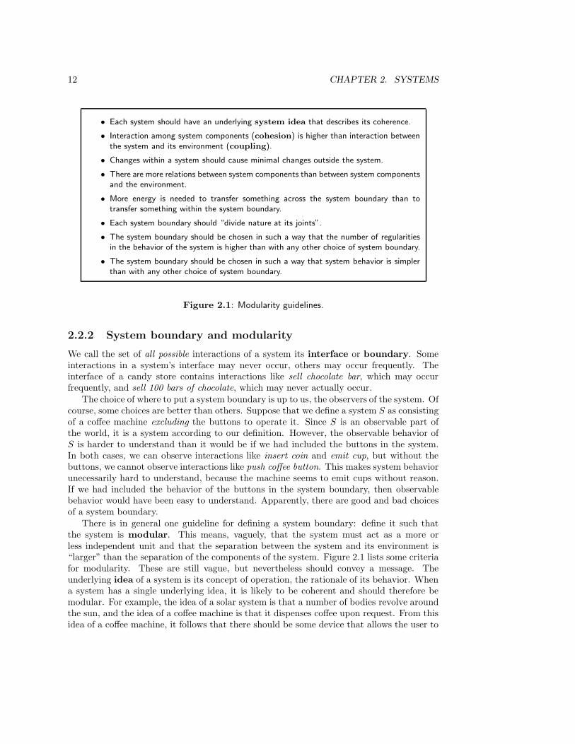
• Each system should have an underlying system idea that describes its coherence.
• Interaction among system components (cohesion) is higher than interaction betweenthe system and its environment (coupling).
• Changes within a system should cause minimal changes outside the system.
• There are more relations between system components than between system componentsand the environment.
• More energy is needed to transfer something across the system boundary than totransfer something within the system boundary.
• Each system boundary should “divide nature at its joints”.
• The system boundary should be chosen in such a way that the number of regularitiesin the behavior of the system is higher than with any other choice of system boundary.
• The system boundary should be chosen in such a way that system behavior is simplerthan with any other choice of system boundary.
Figure 2.1: Modularity guidelines.
2.2.2 System boundary and modularity
We call the set of all possible interactions of a system its interface or boundary. Someinteractions in a system’s interface may never occur, others may occur frequently. Theinterface of a candy store contains interactions like sell chocolate bar, which may occurfrequently, and sell 100 bars of chocolate, which may never actually occur.
The choice of where to put a system boundary is up to us, the observers of the system. Ofcourse, some choices are better than others. Suppose that we define a system S as consistingof a coffee machine excluding the buttons to operate it. Since S is an observable part ofthe world, it is a system according to our definition. However, the observable behavior ofS is harder to understand than it would be if we had included the buttons in the system.In both cases, we can observe interactions like insert coin and emit cup, but without thebuttons, we cannot observe interactions like push coffee button. This makes system behaviorunecessarily hard to understand, because the machine seems to emit cups without reason.If we had included the behavior of the buttons in the system boundary, then observablebehavior would have been easy to understand. Apparently, there are good and bad choicesof a system boundary.
There is in general one guideline for defining a system boundary: define it such thatthe system is modular. This means, vaguely, that the system must act as a more orless independent unit and that the separation between the system and its environment is“larger” than the separation of the components of the system. Figure 2.1 lists some criteriafor modularity. These are still vague, but nevertheless should convey a message. Theunderlying idea of a system is its concept of operation, the rationale of its behavior. Whena system has a single underlying idea, it is likely to be coherent and should therefore bemodular. For example, the idea of a solar system is that a number of bodies revolve aroundthe sun, and the idea of a coffee machine is that it dispenses coffee upon request. From thisidea of a coffee machine, it follows that there should be some device that allows the user to
2.3. SYSTEM STRUCTURE 13
make a request for coffee. Consequently, the system boundary should be chosen in such away that this device, say a button, is included.
2.3 System Structure
2.3.1 Subsystems and aspect systems
Any observable part of the world, except the smallest particle (if it exists), consists ofcomponents that themselves are observable and hence are systems. These componentsare called subsystems. For example, an organization consists of departments, a softwaresystem consists of modules, a house consists of rooms, etc. We will say that a systemis implemented in its subsystems. The behavior of a system is realized by means ofthe behavior of its subsystems, including their interactions with each other and with theenvironment. This means that a system is a collection of subsystems acting as a whole. Anarbitrary collection of mechanical parts is not usefully regarded as a system; a collection ofparts put together to form a car is usefully regarded as a system. The system behaves as itdoes, not only because each of its parts behaves as it does, but because the parts interactin a way such that the total system behavior is realized. A system is thus an organizedcollection of interacting subsystems. As expressed by the modularity heuristics, there is acohesion between the subsystems.
Subsystem boundaries should be chosen in such a way that the subsystems are modular.The entire system is then said to have a modular architecture.
We define an aspect of a system as a subset of all possible interactions of the system.If we observe all subsystems of a system S but restrict our observations to some of theinteractions between them, then we observe an aspect system of S. For example, thefinancial aspect system of an organization consists of all departments of the organization,together with their financial interactions. An information system may be viewed as asubsystem of an organization, consisting of hardware, software, users, user procedures andthe data manipulated by them. Alternatively, we may view it as an aspect system of theorganization, consisting of all departments of the organization and the flows of informationamong them.
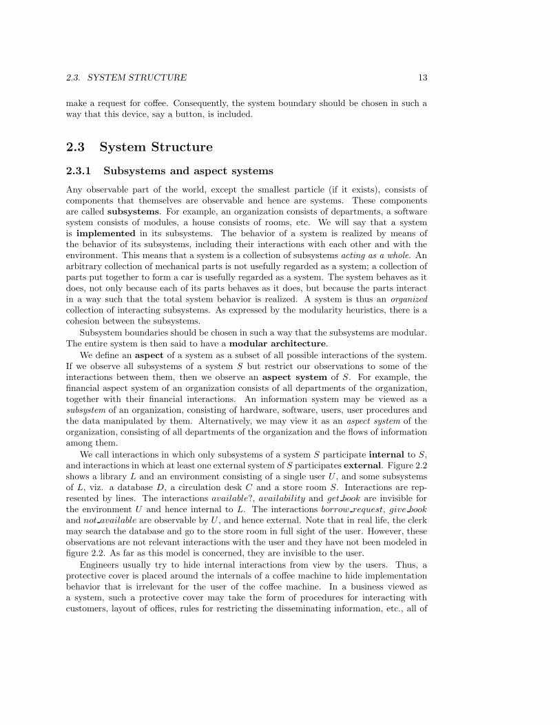
We call interactions in which only subsystems of a system S participate internal to S,and interactions in which at least one external system of S participates external. Figure 2.2shows a library L and an environment consisting of a single user U , and some subsystemsof L, viz. a database D, a circulation desk C and a store room S. Interactions are rep-resented by lines. The interactions available?, availability and get book are invisible forthe environment U and hence internal to L. The interactions borrow request, give book
and not available are observable by U , and hence external. Note that in real life, the clerkmay search the database and go to the store room in full sight of the user. However, theseobservations are not relevant interactions with the user and they have not been modeled infigure 2.2. As far as this model is concerned, they are invisible to the user.
Engineers usually try to hide internal interactions from view by the users. Thus, aprotective cover is placed around the internals of a coffee machine to hide implementationbehavior that is irrelevant for the user of the coffee machine. In a business viewed asa system, such a protective cover may take the form of procedures for interacting withcustomers, layout of offices, rules for restricting the disseminating information, etc., all of
14 CHAPTER 2. SYSTEMS
D: Database
C :Circulation
Desk
U : User
S : Store
Room
L: Library
available?
availability
borrow request
give book
not available
get book
Figure 2.2: Some subsystems and interactions of a library.
which serve to hide internal interactions from external view. Interestingly, there are alsointernal interactions in a business that need no protective cover to be hidden: gossip atthe coffee machine, secret agreements, etc. Indeed, the protective cover of these internalinteractions is itself invisible. People can hide some of their interactions by pretending thatthey never took place. Unlike the metal plate covering the internals of a coffee machine,the cover-up of secret interactions between people can itself be made invisible. This issomething the information analyst will have to deal with when he or she tries to modelsome of the internal business interactions.
2.3.2 A hierarchy of system levels
The world can be divided into levels such that systems that exist at any level are decomposedinto systems at the next lower level. We call this the aggregation or implementationhierarchy in this book. At each level of aggregation, we view the world as a collectionof interacting systems. The behavior of a system is the result of the interactions amongits subsystems and between its subsystems and its environment. For example, figure 2.2shows the interactions between the subsystems of a library and its environment that realizethe borrow interaction between the library and a user. The behavior of the system issometimes said to emerge from the behavior and interaction of the subsystems. Theconcept of emergence indicates that the behavior of the subsystems itself is not sufficientto explain the behavior of the compound system. To explain the compound behavior, onemust additionally take into account the way in which the subsystems interact.
Any partitioning of the world into hierarchical levels is a simplification. For example, thelibrary database may be part of a national network of library databases in which the clerkcan search through the normal database interface. Are these other databases subsystems ofthe library? Is the library a subsystem of this network? Any answer to these questions leavesout an aspect of reality. Nevertheless, hierarchical decomposition is the major tool of thehuman mind for complexity reduction. We use it precisely with the purpose of simplifying
2.3. SYSTEM STRUCTURE 15
Level Examples
Social system An organization, a company division, a set of organizations
Computer-based systemAn information system, an elevator system, an EDI network, aflight simulator
Software systemA database system, an elevator control system, a network com-munication software system
Software subsystemAn error recovery module, an authentication subsystem, ascheduler
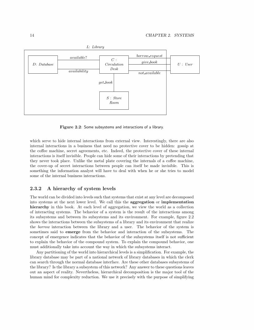
Figure 2.3: A useful aggregation hierarchy from the software engineer’s point of view.
our model of reality. As long as we do not forget that we are dealing with a simplification,hierarchical decomposition allows us to focus on the systems of interest within an otherwisebewildering complexity of systems within systems.
In this book, we will use the system hierarchy shown in figure 2.3. We explain thehierarchy level by level.
• Any system that we build for human use interacts with a human environment. Thetop level of the hierarchy is therefore that of social systems. The social system intowhich our product is embedded may be a human-machine system consisting of oneuser and one machine, or it may be an organization, or a group of organizations. Forexample, a word processing package is used by an individual, an information systemis used by an organization, and an EDI system is used by a group of organizations.
• Taking the archetypical case of a system developed for use in an organization, thenext lower level of aggregation is that of a computer-based system. Examples ofcomputer-based systems are automated information systems, EDI systems, elevatorsystems and flight simulators. Of course, many of these systems may be implementedwithout using computers — paper-based information systems, electromagnetic ele-vator control systems, etc. Figure 2.3 takes a software engineer’s point of view andfocuses on computer-based systems.
• In the cases of interest for us, the computer-based system is composed, at the nextlower level, of hardware and software systems (and possibly other kinds of systems).For example, an information system, viewed as a subsystem of an organization, iscomposed of hardware, software, users, procedures followed by users, and data ma-nipulated by the people and the software. If the computer-based system is composedof hardware and software only, such as an elevator system, then it is customary to callit simply the system and to call the software embedded. Figure 2.3 takes a softwareengineer’s point of view and shows only software systems below the computer-basedsystem level. There are other relevant kinds of systems at this level of aggregation,such as hardware systems, users, and operators. The software engineer must interactwith developers specialized in these other subsystems.
• Software systems are in turn composed of software subsystems, which may be calledpackages, modules, classes, or whatever.
16 CHAPTER 2. SYSTEMS
If we develop a system at some level in this hierarchy, then we must determine what thatsystem must do and how the system is going to do this. A specification of what the systemmust do at that level of aggregation is usually called a requirements specification. This iscontrasted with how the system is realized internally at the next lower level of aggregation,which is called its implementation. The hierarchy of figure 2.3 shows that these distinctionsare meaningless if we do not indicate to which level of the hierarchy we refer. A speci-fication of the implementation of a computer-based system contains a specification of therequirements for its software subsystems, for example. This is not different from the factthat in an apartment building, one person’s floor is another person’s ceiling [76] — but it ismore confusing, because the distinctions we make in system engineering are cast in conceptsrather than in concrete.
To resolve the ambiguity between the what and the how, we should replace the distinctionbetween what a system does and how it does it with the distinction between
• an indication of the level of aggregation we want to refer to, and
• an indication of the observer looking at that level of aggregation.
For example, at the level of libraries, a library user can observe such interactions as borrowa document (figure 2.2). At the same level of aggregation, a publisher can observe otherinteractions, such as buy document. These two observers (user and publisher) see differentobservable behavior of the library but they observe the library at the same level of aggrega-tion. Descending one level of aggregation, the very same observers will see different behaviortoo. At the level of library subsystems, the library user can observe interactions such asborrow request, give book and not available and the publisher observes such interactions asorder document, send invoice and pay for invoice.
2.4 System Behavior
2.4.1 System state
Systems engage in observable behavior by engaging in interactions with their environment.Any system with interesting behavior has a memory of past interactions such that its behav-ior in a current interaction depends upon this memory. The memory of a system is calledthe system state, and the set of all its possible states is called its state space. A systemis called discrete when its state space is a discrete set. Skipping the formal definitions,a state space is discrete when all states in it can be numbered using the natural numbers.For many purposes, organizations can be modeled as discrete systems. Information systemsand many communication systems are also usually specified as discrete systems.
A system is called continuous when state information cannot be encoded by the naturalnumbers but we need real numbers to represent the possible states. In a hybrid system,part, but not all of a state can be encoded by the natural numbers. An example of a hybridsystem is a computer-controlled audio system. The computer control itself is discrete, butit must interface with continuous systems such as potentiometers and speakers, so that thetotal system is hybrid.
The concept of a state is linked to those of the aggregation level and the observerof a system. For example, the state of the library is the sum of the states of each of itssubsystems; in turn, each of these subsystem states is the sum of the states of its subsystems,

2.4. SYSTEM BEHAVIOR 17
etc. We can decompose the state of the library down to any level of decomposition we want.However, for the library user, it is only useful to observe some of the states at the highestlevel of aggregation. A library user can observe whether or not a document is available forborrowing — e.g. by trying to borrow the document. What this means for the state ofthe store room and the database system is not important to the user. For the circulationdesk clerk, on the other hand, these internal states are important. In other words, at anylevel of aggregation, and with respect to an observer or class of observers at that level ofaggregation, part of the state space of a system is observable.
As a consequence, there is no such thing as “the” state space of a system. We mustdefine a state space with respect to a level of aggregation and with respect to an observerof system states at that level of aggregation. This determines which states are observableand at what level of detail they are observable.
2.4.2 System transactions
In this subsection, we restrict the discussion to observable system states. At the start ofan interaction, a system is in a certain (observable) state and at the end of the interaction(assuming the interaction has an end), it is again in in a state. Let us call these states theinitial and final states, respectively. Any state of the system after the initial state of theinteraction and before the final state of the interaction is called an intermediary state of theinteraction. An interaction is called a transaction if it is has no observable intermediarystates. We say that transactions are atomic. Transactions have the atomicity propertythat at any moment in time, either the transaction has occurred or it has not occurred;there is no observable intermediary state in which the transaction has started to occur buthas not yet finished. For example, at the library level of aggregation and with respect tolibrary users, borrow is a transaction that either occurs or does not occur. At the nextlower level of aggregation, and again for library users, transactions like borrow request andgive book can be observed. These lower level transactions implement the higher level borrowtransaction (figure 2.2).
According to Gray [126], the concept of transaction has its roots in contract law. Inmaking a contract, two or more parties negotiate for a while and then make a deal. Thedeal is made binding by some ceremony, like signing a contract or even a simple handshakeor nod. The function of this ceremony is to mark a discrete point in time, before whichthe contract did not exist and after which the contract exists; as far as the observers ofthe negotiations are concerned, there are no intermediary states between non-existence andexistence of the contract. Important observers of the negotiations are the parties to thecontract themselves and, possibly, the judge if there is disagreement about the contract.
Just like the concept of observable state, a transaction is defined at a particular levelof aggregation and with respect to a particular observer, or class of observers. The crucialcharacteristic of a transaction is that, at that level of aggregation and with respect to thoseobservers, it has no observable intermediary states. To implement this, the next lowerlevel of aggregation must offer a rollback mechanism to undo an unsuccessful transactionattempt, and a commitment mechanism by which a successful transaction attempt isturned into a transaction. For example, during the negotiations for the sale of a house,either party can withdraw, after which the transaction attempt has been rolled back andno transaction is said to have taken place. However, after the sales contract is signed, thetransaction has been committed and rollback is not possible.
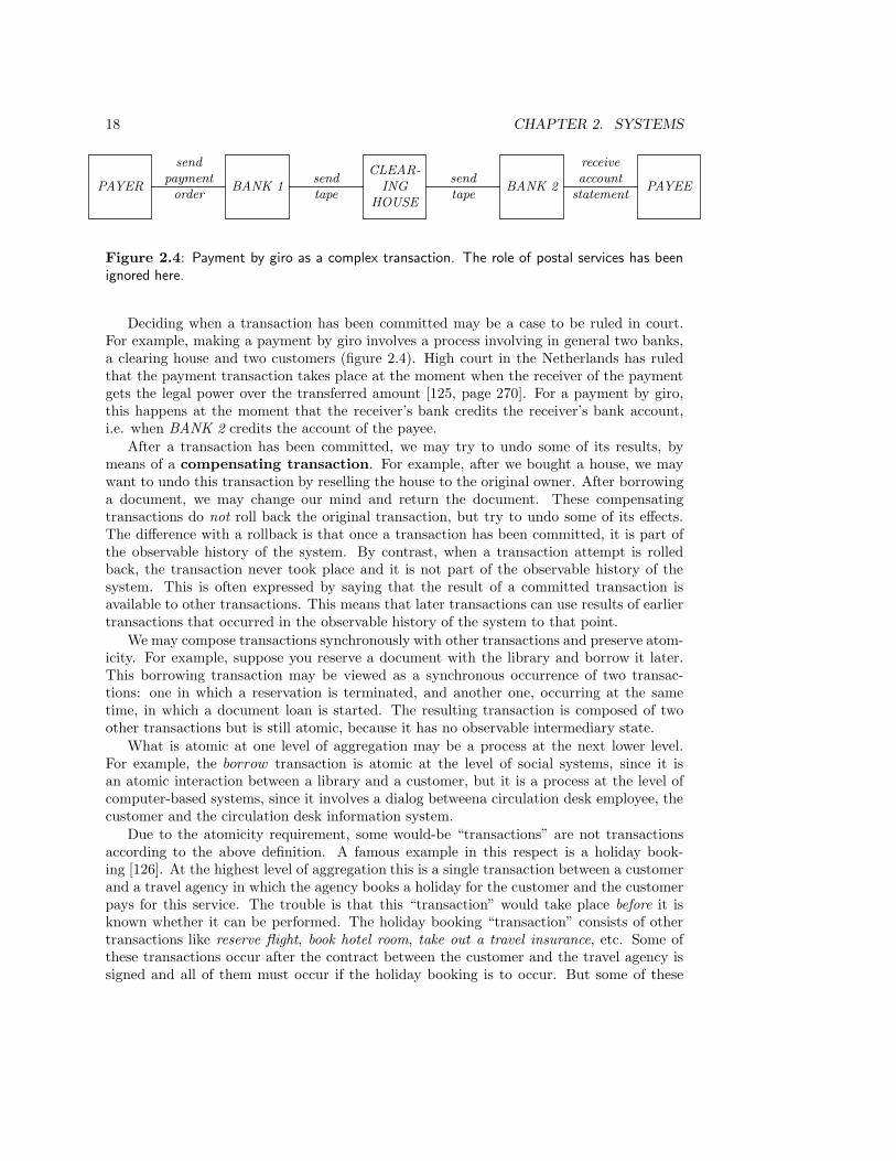
18 CHAPTER 2. SYSTEMS
PAYER BANK 1
send
payment
order
CLEAR-
ING
HOUSE
send
tapeBANK 2
send
tapePAYEE
receive
account
statement
Figure 2.4: Payment by giro as a complex transaction. The role of postal services has beenignored here.
Deciding when a transaction has been committed may be a case to be ruled in court.For example, making a payment by giro involves a process involving in general two banks,a clearing house and two customers (figure 2.4). High court in the Netherlands has ruledthat the payment transaction takes place at the moment when the receiver of the paymentgets the legal power over the transferred amount [125, page 270]. For a payment by giro,this happens at the moment that the receiver’s bank credits the receiver’s bank account,i.e. when BANK 2 credits the account of the payee.
After a transaction has been committed, we may try to undo some of its results, bymeans of a compensating transaction. For example, after we bought a house, we maywant to undo this transaction by reselling the house to the original owner. After borrowinga document, we may change our mind and return the document. These compensatingtransactions do not roll back the original transaction, but try to undo some of its effects.The difference with a rollback is that once a transaction has been committed, it is part ofthe observable history of the system. By contrast, when a transaction attempt is rolledback, the transaction never took place and it is not part of the observable history of thesystem. This is often expressed by saying that the result of a committed transaction isavailable to other transactions. This means that later transactions can use results of earliertransactions that occurred in the observable history of the system to that point.
We may compose transactions synchronously with other transactions and preserve atom-icity. For example, suppose you reserve a document with the library and borrow it later.This borrowing transaction may be viewed as a synchronous occurrence of two transac-tions: one in which a reservation is terminated, and another one, occurring at the sametime, in which a document loan is started. The resulting transaction is composed of twoother transactions but is still atomic, because it has no observable intermediary state.
What is atomic at one level of aggregation may be a process at the next lower level.For example, the borrow transaction is atomic at the level of social systems, since it isan atomic interaction between a library and a customer, but it is a process at the level ofcomputer-based systems, since it involves a dialog betweena circulation desk employee, thecustomer and the circulation desk information system.
Due to the atomicity requirement, some would-be “transactions” are not transactionsaccording to the above definition. A famous example in this respect is a holiday book-ing [126]. At the highest level of aggregation this is a single transaction between a customerand a travel agency in which the agency books a holiday for the customer and the customerpays for this service. The trouble is that this “transaction” would take place before it isknown whether it can be performed. The holiday booking “transaction” consists of othertransactions like reserve flight, book hotel room, take out a travel insurance, etc. Some ofthese transactions occur after the contract between the customer and the travel agency issigned and all of them must occur if the holiday booking is to occur. But some of these
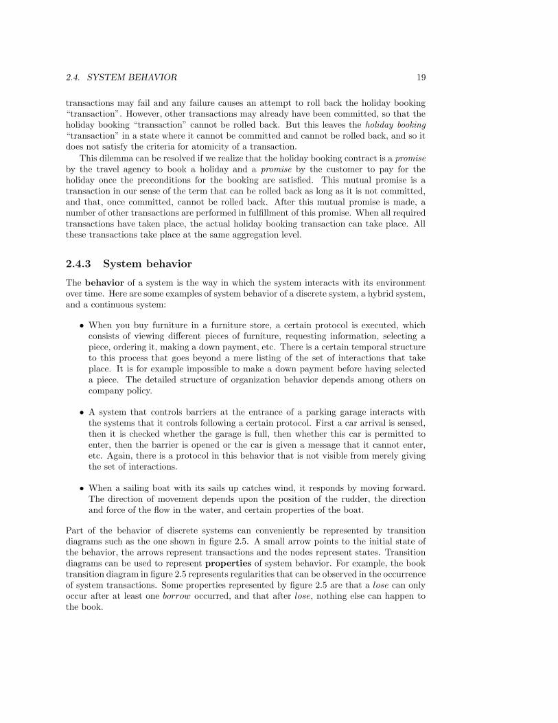
2.4. SYSTEM BEHAVIOR 19
transactions may fail and any failure causes an attempt to roll back the holiday booking“transaction”. However, other transactions may already have been committed, so that theholiday booking “transaction” cannot be rolled back. But this leaves the holiday booking“transaction” in a state where it cannot be committed and cannot be rolled back, and so itdoes not satisfy the criteria for atomicity of a transaction.
This dilemma can be resolved if we realize that the holiday booking contract is a promiseby the travel agency to book a holiday and a promise by the customer to pay for theholiday once the preconditions for the booking are satisfied. This mutual promise is atransaction in our sense of the term that can be rolled back as long as it is not committed,and that, once committed, cannot be rolled back. After this mutual promise is made, anumber of other transactions are performed in fulfillment of this promise. When all requiredtransactions have taken place, the actual holiday booking transaction can take place. Allthese transactions take place at the same aggregation level.
2.4.3 System behavior
The behavior of a system is the way in which the system interacts with its environmentover time. Here are some examples of system behavior of a discrete system, a hybrid system,and a continuous system:
• When you buy furniture in a furniture store, a certain protocol is executed, whichconsists of viewing different pieces of furniture, requesting information, selecting apiece, ordering it, making a down payment, etc. There is a certain temporal structureto this process that goes beyond a mere listing of the set of interactions that takeplace. It is for example impossible to make a down payment before having selecteda piece. The detailed structure of organization behavior depends among others oncompany policy.
• A system that controls barriers at the entrance of a parking garage interacts withthe systems that it controls following a certain protocol. First a car arrival is sensed,then it is checked whether the garage is full, then whether this car is permitted toenter, then the barrier is opened or the car is given a message that it cannot enter,etc. Again, there is a protocol in this behavior that is not visible from merely givingthe set of interactions.
• When a sailing boat with its sails up catches wind, it responds by moving forward.The direction of movement depends upon the position of the rudder, the directionand force of the flow in the water, and certain properties of the boat.
Part of the behavior of discrete systems can conveniently be represented by transitiondiagrams such as the one shown in figure 2.5. A small arrow points to the initial state ofthe behavior, the arrows represent transactions and the nodes represent states. Transitiondiagrams can be used to represent properties of system behavior. For example, the booktransition diagram in figure 2.5 represents regularities that can be observed in the occurrenceof system transactions. Some properties represented by figure 2.5 are that a lose can onlyoccur after at least one borrow occurred, and that after lose, nothing else can happen tothe book.
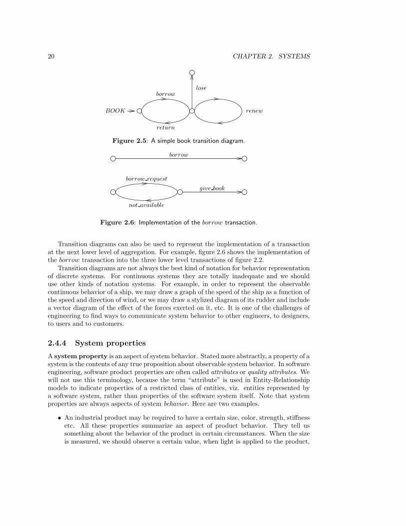
20 CHAPTER 2. SYSTEMS
BOOK
borrow
return
renew
lose
Figure 2.5: A simple book transition diagram.
borrow request
not available
give book
borrow
Figure 2.6: Implementation of the borrow transaction.
Transition diagrams can also be used to represent the implementation of a transactionat the next lower level of aggregation. For example, figure 2.6 shows the implementation ofthe borrow transaction into the three lower level transactions of figure 2.2.
Transition diagrams are not always the best kind of notation for behavior representationof discrete systems. For continuous systems they are totally inadequate and we shoulduse other kinds of notation systems. For example, in order to represent the observablecontinuous behavior of a ship, we may draw a graph of the speed of the ship as a function ofthe speed and direction of wind, or we may draw a stylized diagram of its rudder and includea vector diagram of the effect of the forces exerted on it, etc. It is one of the challenges ofengineering to find ways to communicate system behavior to other engineers, to designers,to users and to customers.
2.4.4 System properties
A system property is an aspect of system behavior. Stated more abstractly, a property of asystem is the contents of any true proposition about observable system behavior. In softwareengineering, software product properties are often called attributes or quality attributes. Wewill not use this terminology, because the term “attribute” is used in Entity-Relationshipmodels to indicate properties of a restricted class of entities, viz. entities represented bya software system, rather than properties of the software system itself. Note that systemproperties are always aspects of system behavior. Here are two examples.
• An industrial product may be required to have a certain size, color, strength, stiffnessetc. All these properties summarize an aspect of product behavior. They tell ussomething about the behavior of the product in certain circumstances. When the sizeis measured, we should observe a certain value, when light is applied to the product,
2.4. SYSTEM BEHAVIOR 21
we should observe a certain color, etc.
• A tree can be tall, old, wide, straight, etc. Again, the meaning of these properties isthat, when certain operations are applied, certain observations will follow.
This view of properties implies that all properties of a system are, at least in principle,observable. A “property” that does not make an observational difference is not, in ourterminology, a property.
Often, it is difficult to indicate an experiment in which we can observe a property. Forexample, software products may be required, among others, to be user-friendly, reliable,portable, flexible and maintainable. All of these properties summarize some aspect ofsoftware product behavior, but which aspects do they summarize exactly? Is a productuser-friendly if novices learn to use it in a short time, or, alternatively, if there are fewhelp requests? Is it portable if it can be easily ported to many kinds of systems? Whatis the appropriate measure of easiness here? Is a software product maintainable if it iswell-documented or if it is modular? Are there unambiguous measures of modularity?
We will say that a property is specified behaviorally if an experiment has been spec-ified that will tell us unambiguously whether a system has the property. If no such experi-ment has been specified, then the property is specificed nonbehaviorally. If a property isspecified behaviorally, then it is always possible to define a transaction in which the prop-erty is observed. This transaction is just the successful completion of the experiment inwhich the property is observed. But then each behavioral property specification indicatessome kind of transaction that the system should be able to perform. For example, if wewant a system to be fast, we can specify that the average response time per day should be0.1 seconds and never exceed 2 seconds, etc. Often, the experiment/transaction in which aproperty P is observed requires the observation of a set of other transactions. Observationof these other transactions is then a precondition of the observation of P .
In software engineering, behaviorally specified properties are often called functionalproperties, and properties for which no observation procedure has been specified are callednonfunctional properties. This terminology is misleading, for it transfers a distinctionof specifications of properties to the properties themselves. We have just seen that allproperties are behavioral, for they all summarize an aspect of system behavior. However,a property specification may be nonbehavioral, because we cannot define an observationprocedure for the property.
Nonbehavioral property specifications give information about a system, because groupsof people may agree on the presence or absence of these properties without using experimen-tal evidence that unambiguously settles the question whether a system has the property.There is agreement among large groups of people about the beauty of Beethoven’s sonatas,the quality of Rembrandt’s paintings, or the user-friendliness of some software product in-terfaces. Typically, there are other groups of people that vehemently disagree about thepresence of these qualities in these products. There is nothing wrong about this. It justshows that the market for these products is not homogeneous. During the development ofa product, nonbehavioral specification of some important properties gives important mar-keting information, and it can motivate developers to build certain useful properties intothe product.
If a behavioral specification of a property cannot be found, it may be useful to givebehavioral specifications of different properties, whose presence indicates the presence of

22 CHAPTER 2. SYSTEMS
the nonbehaviorally specified property, but which are not equal to it. These different prop-erties are then treated as proxies of the intended property. For example, proxies of user-friendliness are “easy to learn” and “easy to use”, which can be specified behaviorally interms of, say, average time needed for training and average number of help requests. Theterm proxy is used to indicate that the behaviorally specified properties are a substitute forthe intended property, and that they approximate the intended property but are not equalto it.
2.5 System Function
So far, we have said that any system has a boundary that separates its internal structurefrom its externally observable behavior. In this section we turn to an aspect of systembehavior present in some but not all systems: the function that a system can have for itsenvironment. A system function is here defined as a service provided by the system to itsenvironment. Here are some examples of systems that have a function for another system.
• The function of the liver for a vertebrate is to transform certain substances in theblood; the organism needs this for its sustained existence.
• The function of an elevator for its users is to transport them from floor to floor; thereason for the existence of elevators is that people do not like walking the stairs.
• The function of an information system for an organization is to provide members ofan organization with useful data; they need this data to be able to communicate witheach other effectively. The reason that information systems exist is that organizationscannot continue to exist for long without a properly functioning (manual or automatic)information system.
We will use the term “function” also in the derivative sense of useful behavior. The determi-nation of required product functions is then the determination of useful product behavior.
A system that has a function for its environment provides for a need or desire in itsenvironment. The liver answers a need of its environment, and the elevator answers a desireof its users. The needs of people may differ from the desires of people: managers may desirean information system, but perhaps what is really needed is a change in organizationalprocedures. In product development, the developer and the client should reach agreementabout the client’s needs such that what the developer perceives to be the client’s needsis indeed what the client desires. In this book, we therefore define a need as the lack ofsomething desirable.
If a system has a function, then there is always some system in its environment whoseneeds (desires) are answered by interacting with the system. We call this system the userof the system. The function of a system is thus always relative to a user and a need is forus always a user need. The same system can have different functions for different usersbecause these have different needs. If we take away all users, then the system does not haveany function.
2.5.1 Products
Outside the realm of biology, most natural systems have no function in the above sense. Forexample there is no environment that has a need which is fulfilled by the planet Jupiter.

2.5. SYSTEM FUNCTION 23
In the universe of physics, things just exist and behave. In the universe of social systems,however, some natural systems occur in contexts where they have a certain function forman. For example, the sun provides light and warmth to living beings on earth, and amountain can provide aesthetic pleasure to tourists. In the realm of biology, we find manycases in which one system (e.g. an organ) has a function for another (e.g. an organism).
In system development, we are not interested in natural systems with a function, butin artificial systems with a function. We call these systems products. A product has twoproperties:
• it is manufactured, built, developed, or otherwise created by man, and
• it is created in order to provide a function to its user.
Thus, like the liver, the reason for existence of a product is the provision of a service toits environment; but unlike the liver, it is manufactured by man in order to provide thisservice. According to this definition, a coffee machine is a product built to provide its userswith coffee, and an information system is a product built to provide an organization withuseful data.
We call the most general function of the product the product idea. For example, theproduct idea of an elevator is that
upon request, it should transport people from floor to floor.
The statement of a product idea should be succinct and clear. Generally, a clear productidea leads to well-defined system boundaries and hence to modular systems (figure 2.1).
If any system created by man to provide a service to its environment is a product, thena business is a product, too. The users of the business are called customers and the functionof the product is called the mission of the business. The mission statement of a businesssays “who we are and what business we are in”. For example, the mission of a hospital is
the care and treatment of the ill.
Mission statements, like product ideas, should be succinct. Like products, implementing anorganization according to a simple coherent underlying idea enhances the modularity of theorganization and increases the regularity and simplicity of its behavior.
A product idea or business mission can be decomposed into objectives that the productor business must realize. Each business is managed in such a way that these objectives arereached (or so one hopes). Each business therefore displays the purposive behavior thatsome people take to be characteristic of systems in general. In this book, we take a moregeneral view of systems. Thus, products like information systems or coffee machines donot engage in purposive behavior but nevertheless are viewed as systems. Note that therealization of product objectives is the task of designers and maintenance personnel.
2.5.2 Functions of computer-based systems
Because computers are data manipulation systems, computer-based systems provide func-tions in which data manipulation plays an essential role:
• Computation. Computer-based systems can perform complex computations fasterand with less errors than we do. This is useful for us.
24 CHAPTER 2. SYSTEMS
• Registration. Computer-based systems often register data. This is useful for usbecause we need an external memory to supplement our own fallible memories. More-over, law often prescribes that we keep external records of business transactions.
• Communication. Because a computer-based system allows us to read data that hasbeen written earlier, it allows asynchronous communication between people at thesame location at different times (information systems). This can be extended to syn-chronous or asynchronous communication between nodes at geographically differentlocations (EDI systems).
• Control. Embedded systems often send commands to machines in their environment,to make them behave in a certain way that is useful for us.
Traditionally, computer-based systems are classified as oriented towards one of these func-tions. In computing-intensive systems, computation outweighs registration and control.An example is a simple pocket calculator. Another example is a decision-support systemthat performs linear programming or other optimization tasks, or that contains an econo-metric model to be used for computing what-if scenarios. In data-intensive systems, largeamounts of data are registered and relatively simple computation and control functions areperformed. Classical examples are database systems and transaction-processing systems. Incommunication-intensive systems, a set of nodes performing relatively simple compu-tations and having little memory is connected by a network with heavy traffic. An exampleis a telephone system. In control-intensive systems, part of the environment is controlledbut relatively simple computations are performed and few data are stored. Examples arecontrol software for an elevator system, a cruise control system, or a chemical processingplant.
With the advent of telematics systems, EDI systems and integrated manufacturing sys-tems, the borders between these systems disappear. All these systems have more controlfunctions than classical data-intensive systems, manipulate more data than classical control-intensive systems, and contain more communication than the other kinds of systems.
2.6 The Why, the What and the How
A specification of observable product behavior is a specification of what the product does, aspecification of the product function is a specification of why it does this, and a specificationof its implementation is a specification of how it does this. The major concern in these threespecifications is that of utility. Utility is a relation between something that has a use andsomething else that benefits from this use. There are two utility relations to be considered(figure 2.7).
• The service that a product delivers to its environment is the benefit that the environ-ment has from the product. Service is a relation between the behavior of the productand the needs of the user.
• The correctness of the implementation is the degree to which the implementation ac-tually realizes the required behavior of the product. Correctness is a relation betweena specification of observable behavior and an implementation.
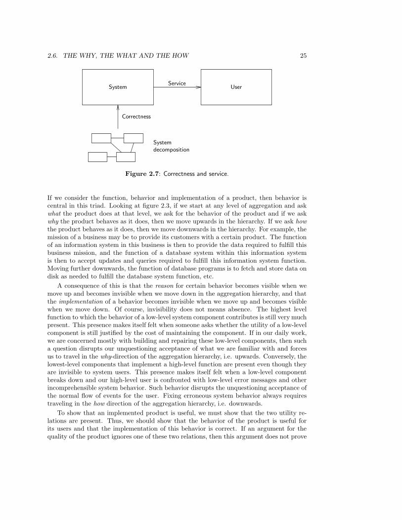
2.6. THE WHY, THE WHAT AND THE HOW 25
System UserService
Correctness
Systemdecomposition
Figure 2.7: Correctness and service.
If we consider the function, behavior and implementation of a product, then behavior iscentral in this triad. Looking at figure 2.3, if we start at any level of aggregation and askwhat the product does at that level, we ask for the behavior of the product and if we askwhy the product behaves as it does, then we move upwards in the hierarchy. If we ask howthe product behaves as it does, then we move downwards in the hierarchy. For example, themission of a business may be to provide its customers with a certain product. The functionof an information system in this business is then to provide the data required to fulfill thisbusiness mission, and the function of a database system within this information systemis then to accept updates and queries required to fulfill this information system function.Moving further downwards, the function of database programs is to fetch and store data ondisk as needed to fulfill the database system function, etc.
A consequence of this is that the reason for certain behavior becomes visible when wemove up and becomes invisible when we move down in the aggregation hierarchy, and thatthe implementation of a behavior becomes invisible when we move up and becomes visiblewhen we move down. Of course, invisibility does not means absence. The highest levelfunction to which the behavior of a low-level system component contributes is still very muchpresent. This presence makes itself felt when someone asks whether the utility of a low-levelcomponent is still justified by the cost of maintaining the component. If in our daily work,we are concerned mostly with building and repairing these low-level components, then sucha question disrupts our unquestioning acceptance of what we are familiar with and forcesus to travel in the why-direction of the aggregation hierarchy, i.e. upwards. Conversely, thelowest-level components that implement a high-level function are present even though theyare invisible to system users. This presence makes itself felt when a low-level componentbreaks down and our high-level user is confronted with low-level error messages and otherincomprehensible system behavior. Such behavior disrupts the unquestioning acceptance ofthe normal flow of events for the user. Fixing erroneous system behavior always requirestraveling in the how direction of the aggregation hierarchy, i.e. downwards.
To show that an implemented product is useful, we must show that the two utility re-lations are present. Thus, we should show that the behavior of the product is useful forits users and that the implementation of this behavior is correct. If an argument for thequality of the product ignores one of these two relations, then this argument does not prove
26 CHAPTER 2. SYSTEMS
its claim. In order to produce such an argument, it is important that links are maintainedbetween related specifications at all levels in the hierarchy such that each specification islinked to specifications (at higher levels) that justify it and to specifications of compo-nents (at lower levels) that implement it. A set of specifications for which these links aremaintained is called traceable. (Although traced would be more appropriate, we followaccepted terminology here.) Behavior specifications should be traceable to specifications ofuser needs and system objectives on the one hand and to specifications of subsystems onthe other. Forward traceability of a specification is the property that each part of thespecification can be traced to specifications of lower-level components that implement it.Forward traceability requires maintenance of links in the how-direction, which is down theaggregation hierarchy. Backward traceability of a specification is the property that foreach part of the specification, it is clear why it is included. This is the maintenance of linksin the why-direction, which is up the aggregation hierarchy. Backward traceability ensuresthat the impact of changing a component of a specification can be traced to changes inproduct behavior and in the service that the product delivers to its user. The realization oftraceability is particularly important when user needs, product objectives, behavior speci-fications or system decompositions are changed and the impact of such a change must beestimated.
2.7 The Universe of Discourse of Computer-based Sys-tems
Computer-based systems contain software systems, and software manipulates data. Now,the essence of data is that they mean something. Data items are symbols that, for theirreaders and writers, refer to something. The part of the world to which the manipulateddata refers is called the universe of discourse (UoD) of the system. The UoD of a systemis sometimes called the domain of the system, but we will not use that term in this way.We give some examples of computer-based systems and their UoD.
• The universe of discourse of an order administration system contains suppliers, orderedmaterial, orders, deliveries, etc.
• The universe of discourse of an elevator control system consists of buttons, requestsfor service, elevators and their movement, lights that can be told to switch on and off,doors that can be told to open and close, etc.
• The universe of discourse of an EDI system connecting different businesses in a harborconsists of cargo to be moved, container shipments, insurances, payment obligations,etc.
• The UoD of a pocket calculator is the abstract, mathematical world of arithmetic. Thepocket calculator registers no events that occur in its UoD, nor does it send controlsignals to its UoD, because nothing happens in its UoD. Its function is to indicaterelations between elements of its UoD.
• A decision support system is an information system that registers events in its UoD,and that contains an econometric model of the UoD. It registers no events but com-

2.8. SUMMARY 27
Softwaresystem
Conceptualmodelof UoD
UoD
Figure 2.8: The UoD and its conceptual model.
putes a number of relations that exist in this abstract, mathematical model. Forexample, it can compute possible futures according to this model,
In order to achieve a shared understanding of the meaning of data manipulated by acomputer-based system, users, developers and builders of the system must have a sharedmodel of the UoD of that system. The function of this model is to act as the semanticstructure in which the manipulated data are interpreted by all relevant people. The modelmust be understood by the users of the system, because they would otherwise misunder-stand the meaning of the data, and it must be understood by the developers and buildersof the system, because they must know what are the meaningful data manipulations thatthey have to make the system perform. In addition, to avoid misunderstandings about themeaning of the data manipulations of the system, users and developers must have the sameunderstanding of the model of the UoD. To emphasize the important role of the model inthe understanding of the behavior of a data manipulating system, we call it a conceptualmodel of the UoD of the system. A conceptual model of the UoD is an abstract represen-tation of the behavior of the UoD, understandable and understood in the same way by theusers and developers of the system. The term “conceptual” refers to the fact that the modelconsists of concepts by means of which users and developers interpret and observe the UoD.Put more prosaically, a conceptual model of a UoD is a pair of spectacles by which peoplecan observe the UoD. Figure 2.8 illustrates the situation.
Later, we will also look at conceptual models of the system under development (SuD).The hallmark of conceptual models is that they are conceptual structures used as frameworkfor communication between people. The communication may be about a UoD, a computer-based system, a software system or any other kind of system.
2.8 Summary
In the systems approach, the world consists of building blocks called systems. Any actualor possible observable part of the world is a system. Any observation of the system is aninteraction between the system and its environment, and conversely any interaction withthe system is an observation of that system. The system interface or boundary is the setof all possible interactions of the system and the environment of the system is the part ofthe world it interacts with. Each system has a state space, where a state is the memorythe system has of past behavior. A system is discrete if its state space is a discrete setand continuous if its state space is a continuous set. It is hybrid if a projection of itsstate space is a discrete set and another projection is a continuous set. A transaction isa smallest interaction between a system and its environment, i.e. an interaction that has
28 CHAPTER 2. SYSTEMS
no intermediary states. Whether or not an interaction is considered to have intermediarystates is a matter of choosing a level in the aggregation hierarchy at which to observe thesystem.
A system is called modular if its boundary has been chosen in such a way that therewould be less regularities in its behavior, and more complexity, with any other choice ofboundary. In addition, there should be much cohesion within the system but loose couplingbetween systems.
The structure of a system is the way it is composed of subsystems and the behavior of asystem is the way it interacts with its environment. Often, some of this can be representedby transition diagrams, but in most cases, other kinds of notations must be used additionally.A property summarizes an aspect of system behavior. All properties are observable, butsome properties may be hard to specify behaviorally. For these properties, it may be usefulto specify proxies for which behavioral specifications can be given.
A function of a system for another system is a service that the first system delivers tothe second. System developers develop products, which are systems that are built to providea service to their environment. The reason for existence of a product is (or should be) thatit has a function for another system. The basic function of a product should be describableas a product idea.
Computer-based systems have at least one of the functions of computation, registra-tion, communication, and control. The traditional division of computation-intensive, data-intensive, communication-intensive and control-intensive systems tends to be blurred whenwe move to EDI, telematics and manufacturing control systems.
System structure, behavior and function cover the how, what and why perspectives fromwhich we can view a system. There are two utility relations between these views: systemstructure must be correct with respect to required system behavior, and the behavior itselfmust deliver a service to the users. A collection of system specifications at different levels ofaggregation is called traceable if each part of each specification is linked to specifications ofthe components that implement it (forward traceability) and to the justification for includingthis part in the specification (backward traceability).
Each computer-based system manipulates data that have meaning in a universe of dis-course (UoD). A conceptual model of the UoD represents the shared interpretation thatusers and developers should have of this data.
2.9 Exercises
1. A coffee grinder is connected to a power plug, has a reservoir for coffee beans, anon/off switch, and a light that indicates its on/of status.
(a) What is the function of the grinder?
(b) Describe the interface of the grinder, including the systems with which it inter-faces.
(c) Is the grinder a discrete, continuous or hybrid system?
2. The interface between a grocery store and its customers can be described at severallevels of aggregation. At the highest level, there is a simple interface with only onetransaction, sell grocery.
2.9. EXERCISES 29
(a) Decompose this high level transaction into lower level transactions and decom-pose one of lower level transactions again into still lower level transactions.
(b) At each of the three levels of aggregation, the grocery store has another interface.Some observers are interested only in the highest level, some in the next lowerlevel, etc. For each level, give an observer who is interested in observing thesystem at that level.
3. An observable system state may be an equivalence class of internal system stateswhose difference is not observable. For each of the following systems and observers,give an example of an internal system state that is not observable by the observer.State the reason why you think that the internal state is not observable.
(a) A coffee machine and its user.
(b) A text editor and its user.
(c) A fashion store and a potential buyer.
(d) A database system for the library circulation desk, and its user.
(e) A database system for the library circulation desk, and a library user.
4. Figure 2.4 shows a series of communications between systems that occurs when a giropayment is made.
(a) the communication between the banks and their customers takes place throughthe postal services, and the communications between the banks and the clearinghouse takes place through a special transport company specialized in armedtransports. Add these systems to the communication diagram.
(b) Describe the process that a payment goes through by means of a transitiondiagram. First, draw the diagram of the normal process and next, at each stage,add abnormal events by which the pay by giro transactions may go wrong. Forexample, the payment order may get lost in the post, etc. Finally, take care thatthe whole payment process implements the pay by giro transaction by adding,where necessary, rollback actions.
5. Suppose an artist uses a hammer as part of a piece of art. Is the hammer then still aproduct?
6. We can represent finite state machines by a transition diagram, but also by a regularexpression. For example, a.(c.b+c.d) is a regular expression in which the dot representssequence and the plus represents choice.
(a) Draw the transition diagram corresponding to this expression.
(b) Draw the transition diagram of a.c.(b + d).
(c) Do both diagrams represent the same behavior? Explain your answer.
30 CHAPTER 2. SYSTEMS
2.10 Bibliographical Remarks
The systems approach. Two important roots of the systems approach lie in biologyand in engineering. In the 1920s, the biologist Von Bertalannfy argued that an explanationof the functioning of biological organisms required a level of explanation above that ofphysical and chemical processes because biological organisms persist for some time undersometimes adverse circumstances [32]. According to Von Bertalannfy, this goes counterto the second principle of thermodynamics, which says that any state change in a closedsystem decreases the energy available for work in the system. He maintained that biologicalorganisms must be seen as systems that interact with their environment with the purposeof extracting energy from the environment to sustain themselves. The concept of a systemis thus connected to the idea of purposive behavior.
In the 1940s, the mathematician Norbert Wiener studied goal-seeking mechanisms thatcould be used to improve automatic radar, and this led to the idea of feed-back loops toimplement purposive behavior in machines [144]. Wiener termed the study of goal-directedsystems cybernetics and published a book about this in 1948 [361]. In engineering, too, theconcept of a system has been connected with the idea of purposive behavior. The connectionof systems theory with feedback loops and purposive behavior has been ignored in thischapter because it is not necessary to understand the structure of product development.Checkland [63] gives a grand vision of the history of the systems approach.
The systems approach in computer science. An important application of the sys-tems approach in computer science, especially of the idea of modularity, is the method ofstructured analysis and structured design [84, 378]. Structured analysis is discussed in chap-ter 10. General systems ideas in this approach go back to work by G.M. Weinberg [357],C.W. Churchman [67] and Ross and Schoman [294]. Another important application of thesystem approach is Checkland’s soft systems methodology [63, 62].
Automata theory. The classical definition of the concept of a state of a deterministicfinite-state system is given by Minsky [233, pp. 13 ff.]. A state concept that is useful inthe context of communicating systems is given by Milner [231, 232]. Milner defines variousnotions of equivalence on transition diagrams, such that two equivalent diagrams representthe same observable behavior. Another good survey of equivalence notions can be found inBaeten and Weijland [18].
Modularity and complexity reduction. The building blocks view of the world whichpervades systems theory is primarily a method of complexity reduction. Descartes had al-ready advocated this method in the seventeenth century. To understand an object, he said,we must decompose it into its parts and repeat this process until we reach a clear under-standing of the simplest building blocks. Then we recompose to achieve an understandingof the whole [85, pages 15–20].
In addition to being indispensable as a method to understand a complex system, re-duction to simpler subsystems is advocated by Simon [314] as the only way we can builda complex system. By reducing a complex system to simpler subsystems, we can defineintermediary products that have a stability of their own and can be used in several ways athigher levels. Structured programming uses the same idea [75] to reduce the complexity of a
2.10. BIBLIOGRAPHICAL REMARKS 31
program to manageable chunks, and, as said before, structured design [378] and structuredanalysis [84] took these ideas to earlier stages in the system development process. Thesame idea is central in structured computer organization [337] and the leveling of computersystems in general.
Modularity heuristics. The requirement that a system must have an underlying ideathat defines its coherence is common in industrial product development [289]. Lawson [190]emphasizes the importance of an underlying product idea for successful software systemdesign. Tully [348, pages 57–60] expresses the same idea. The close cohesion and loosecoupling heuristics are well-known from Structured Design [251, 378]. The heuristic thata change inside a system should cause a minimal change outside the system is given byPage-Jones [252]. Parnas’ [253] heuristic that each module should hide a design decision(so that changing the decision will not affect other modules) is special case of this.
System behavior and properties. The concept of a transaction is well-known in data-base research. A readable introduction, which puts the concept in historical perspective, isgiven by Gray [126]. A practical introduction to the specification of required system prop-erties is given by Gilb [115], who stresses observability of the properties in experiments.Gause and Weinberg [111] is a treasure island full of insights and heuristics in the speci-fication of required system properties. “Nonfunctional properties” are treated extensivelyby Vincent, Waters and Sinclair [350]. A brief introduction is given by Ould [250]. Otheruseful sources are Davis [77] and Yeh [374].
System levels. The idea of system leveling is central in general systems theory. Bould-ing [49] and Checkland [63] published two influential hierarchies. The idea of leveling iscoupled with complexity reduction and modularity, as well as with the concept of emergentbehavior [346]. According to this idea, system behavior cannot be explained merely by thebehavior of its components, but must be explained by referring to the way in which thesecomponents are put together. It is also the key to the disentanglement of the confusionabout the difference between requirements and implementation. Davis [77, pages 17–18]gives a very clear explanation of this. Hatley and Pirbhai [141] use it as a basis for theirstructured requirements specification and system decomposition method.
System function. The definition of system function as service for the environment istaken from In’t Veld [349]. A very good introduction to system concepts, including that offunction, is given in the first few chapters of Katz and Kahn [170].
The UoD. The concept of UoD was introduced by the 19th century logician De Morganto stand for the whole of some definite category of things under discussion [181]. It iscentral in the ISO report Concepts and Terminology for the Conceptual Schema and theInformation Base [127] and to the NIAM method [244].
Conceptual models. The term “conceptual model” is often defined vaguely as a set ofconcepts from a given reality that can be used to describe a set of data and manipulationsto operate on those data [25, pages 6, 26]. In this meaning, the Entity-Relationship (ER)

32 CHAPTER 2. SYSTEMS
approach to data modeling is a conceptual model. Sometimes, conceptual models are iden-tified with ER-like models. We will not follow this usage in this book. Loucopoulos andKarakostas [198] define conceptual models as cognitive structures used for the purposes ofunderstanding and communicating aspects of the physical and social world around us. Thisusage of the term arose in the field of data modeling but has a wider applicability than justER modeling [51]. In this book, we use the term in this sense.
Chapter 3
Product Development
3.1 Introduction
In this chapter, we define product development as a rational problem solving process. Theproblem to be solved by product development is that there is a need to be met; the solutiondelivered is a specification of a product that would meet this need. Section 3.2 distinguishesclient-oriented development from market-oriented development and identifies the tasks inthese two kinds of development. Once a product is used, the needs of its users evolve andhence a point may be reached where the product must be adapted to meet these changedneeds. In section 3.3, we identify product evolution as a nonterminating alternation betweenproduct (re)development and product use. An important characteristic of product evolutionis that the effects of a product on the satisfaction of the client or consumer are evaluatedafter the product is built and delivered. In section 3.4, we contrast this with productengineering, in which design choices are made based on an evaluation of likely effects ofalternative product designs before any of the specified designs is implemented.
In chapter 2, we saw that computer-based systems manipulate data that has a meaningin a UoD. During the development of a computer-based system, developers must makea descriptive model of the UoD. The method to find such model is the empirical cycle,discussed in section 3.5. The empirical cycle is an application of the rational problemsolving method to find an appropriate model of the world. This is the mirror image of theengineering cycle, which is an application of the rational problem solving method to find aproper intervention in the world.
In section 3.6, we combine the engineering cycle with the hierarchy of system levelsidentified in the previous chapter to yield a simple framework within which we can placethe requirements engineering methods reviewed in part II.
3.2 Client-oriented and Market-oriented Development
Product development is a process in which a specification is delivered of a product thatwould satisfy an identified need (figure 3.1). For example, the development of a new kindof car ends in a specification of a car design that would satisfy the needs of a certain nichein the market. Implementation of the product specification lies outside the development
33

34 CHAPTER 3. PRODUCT DEVELOPMENT
DevelopmentNeedsProduct
specification
Figure 3.1: The essence of development is the transformation of a need into a solution thatis expected to satisfy this need.
process so in a way, product development would more appropriately be called productspecification development. However, we will stick to the shorter expression. We will usethe terms “system development” and “product development” as synonyms, because in thisbook, all system specifications are product specifications.
The starting point of a development process is a need in the environment of the futureproduct. This need can exist in an individual user or in a market. In the first case, wecall the development process client-oriented and in the second case, we call it market-oriented. The client has a desire for a product and as we will see below, the client mayalso pay for development, or pay for the product, or use the product, or all of these atthe same time. Examples of client-oriented development are designing a suit for a client,designing a kitchen to be installed in a house on assignment of the inhabitant, specifyingan information system for a business, and specifying control software for a nuclear reactorsystem. Examples of market-oriented development are designing a new type of vacuumcleaner, developing a new type of printing equipment, developing a new version of a wordprocessing package and developing control software for a type of elevator system. Client-oriented and market-oriented development are distinguishable from each other in a numberof ways.
• In client-oriented development, the need that starts the development process is expe-rienced by the client. Because the client experiences it to exist, it exists. In market-oriented development the need is perceived by marketing specialists. There is alwaysroom for debate whether the perceived need really exists in the market.
• In market-oriented development, a specification of a product type is delivered, such as atype of vacuum cleaner, a type of printer, or a software package. Product developmentresults in a description of a mass production process by which a series of instancesof the type is produced. Client-oriented development on the other hand delivers anindividual solution, such as the drawings for a tailor-made suit, the plans for a house,or a specification of an information system. Only one instance of an implementationis produced.
• In client-oriented development, not only the product, but also the client itself is anindividual. This creates room for the client to change his or her mind during deve-lopment and to demand a high degree of satisfaction of his or her needs. In market-oriented development, on the other hand, the variability of needs is much less, becausethese are not subject to individual whims. Consumers do not expect as high a degreeof satisfaction as clients do.
There are borderline cases that can be classified in both classes. A project in which a blockof houses is built is client-oriented in as far as there is a client who commissions the project,but market-oriented in as far as the client intends to sell the houses in the block on the
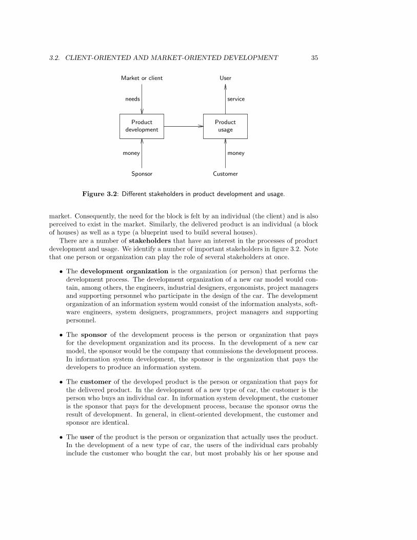
3.2. CLIENT-ORIENTED AND MARKET-ORIENTED DEVELOPMENT 35
Productdevelopment
Productusage
Market or client
needs
Sponsor
money
User
service
Customer
money
Figure 3.2: Different stakeholders in product development and usage.
market. Consequently, the need for the block is felt by an individual (the client) and is alsoperceived to exist in the market. Similarly, the delivered product is an individual (a blockof houses) as well as a type (a blueprint used to build several houses).
There are a number of stakeholders that have an interest in the processes of productdevelopment and usage. We identify a number of important stakeholders in figure 3.2. Notethat one person or organization can play the role of several stakeholders at once.
• The development organization is the organization (or person) that performs thedevelopment process. The development organization of a new car model would con-tain, among others, the engineers, industrial designers, ergonomists, project managersand supporting personnel who participate in the design of the car. The developmentorganization of an information system would consist of the information analysts, soft-ware engineers, system designers, programmers, project managers and supportingpersonnel.
• The sponsor of the development process is the person or organization that paysfor the development organization and its process. In the development of a new carmodel, the sponsor would be the company that commissions the development process.In information system development, the sponsor is the organization that pays thedevelopers to produce an information system.
• The customer of the developed product is the person or organization that pays forthe delivered product. In the development of a new type of car, the customer is theperson who buys an individual car. In information system development, the customeris the sponsor that pays for the development process, because the sponsor owns theresult of development. In general, in client-oriented development, the customer andsponsor are identical.
• The user of the product is the person or organization that actually uses the product.In the development of a new type of car, the users of the individual cars probablyinclude the customer who bought the car, but most probably his or her spouse and
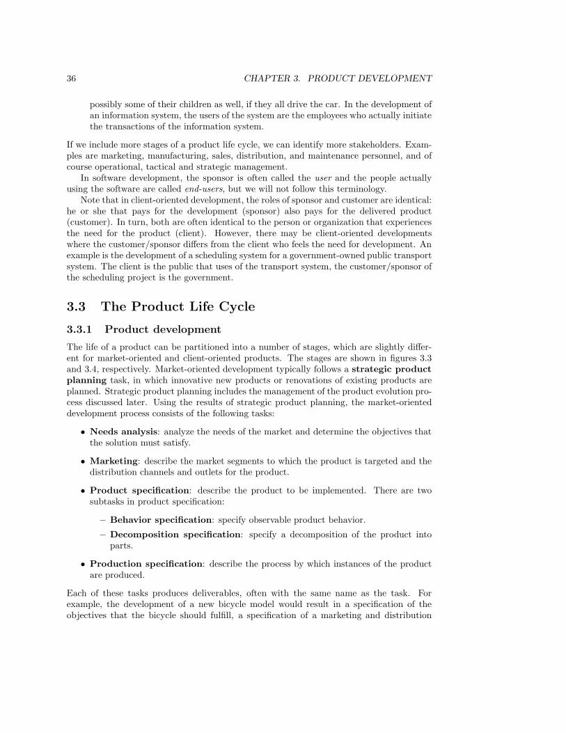
36 CHAPTER 3. PRODUCT DEVELOPMENT
possibly some of their children as well, if they all drive the car. In the development ofan information system, the users of the system are the employees who actually initiatethe transactions of the information system.
If we include more stages of a product life cycle, we can identify more stakeholders. Exam-ples are marketing, manufacturing, sales, distribution, and maintenance personnel, and ofcourse operational, tactical and strategic management.
In software development, the sponsor is often called the user and the people actuallyusing the software are called end-users, but we will not follow this terminology.
Note that in client-oriented development, the roles of sponsor and customer are identical:he or she that pays for the development (sponsor) also pays for the delivered product(customer). In turn, both are often identical to the person or organization that experiencesthe need for the product (client). However, there may be client-oriented developmentswhere the customer/sponsor differs from the client who feels the need for development. Anexample is the development of a scheduling system for a government-owned public transportsystem. The client is the public that uses of the transport system, the customer/sponsor ofthe scheduling project is the government.
3.3 The Product Life Cycle
3.3.1 Product development
The life of a product can be partitioned into a number of stages, which are slightly differ-ent for market-oriented and client-oriented products. The stages are shown in figures 3.3and 3.4, respectively. Market-oriented development typically follows a strategic productplanning task, in which innovative new products or renovations of existing products areplanned. Strategic product planning includes the management of the product evolution pro-cess discussed later. Using the results of strategic product planning, the market-orienteddevelopment process consists of the following tasks:
• Needs analysis: analyze the needs of the market and determine the objectives thatthe solution must satisfy.
• Marketing: describe the market segments to which the product is targeted and thedistribution channels and outlets for the product.
• Product specification: describe the product to be implemented. There are twosubtasks in product specification:
– Behavior specification: specify observable product behavior.
– Decomposition specification: specify a decomposition of the product intoparts.
• Production specification: describe the process by which instances of the productare produced.
Each of these tasks produces deliverables, often with the same name as the task. Forexample, the development of a new bicycle model would result in a specification of theobjectives that the bicycle should fulfill, a specification of a marketing and distribution
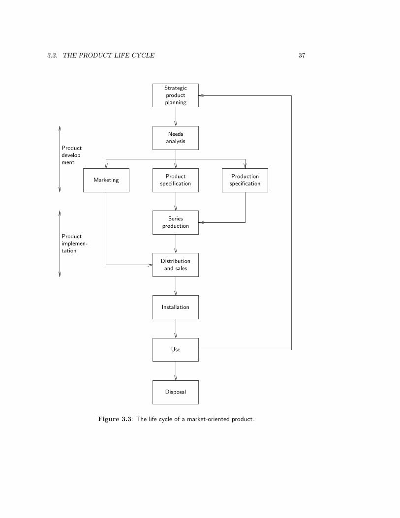
3.3. THE PRODUCT LIFE CYCLE 37
Needsanalysis
Strategicproductplanning
Productspecification
MarketingProductionspecification
Seriesproduction
Distributionand sales
Installation
Use
Disposal
Productdevelopment
Productimplemen-tation
Figure 3.3: The life cycle of a market-oriented product.
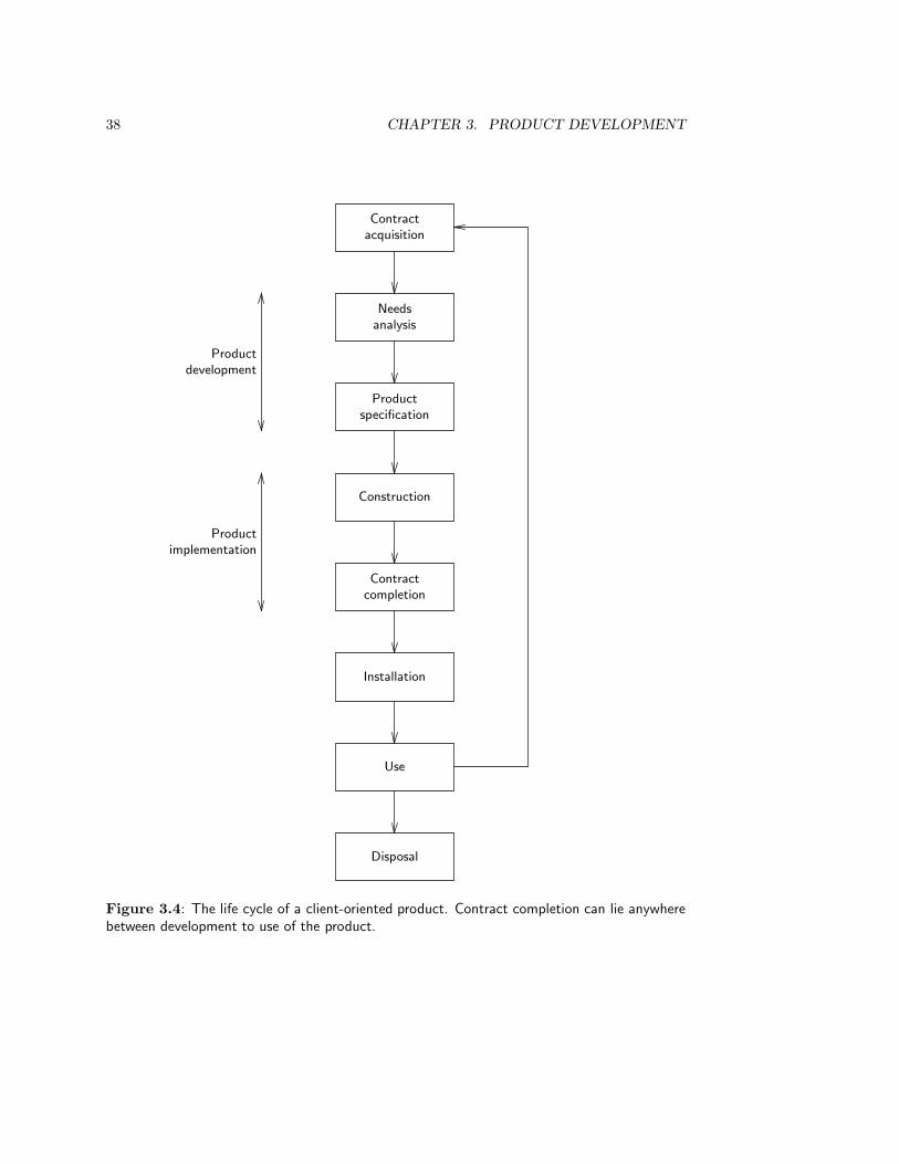
38 CHAPTER 3. PRODUCT DEVELOPMENT
Needsanalysis
Productspecification
Construction
Contractcompletion
Installation
Use
Disposal
Contractacquisition
Productdevelopment
Productimplementation
Figure 3.4: The life cycle of a client-oriented product. Contract completion can lie anywherebetween development to use of the product.
3.3. THE PRODUCT LIFE CYCLE 39
plan, a specification of the observable behavior of the bicycle in different circumstances, aspecification of the decomposition into parts, and a specification of the production processthat describes how the parts can be assembled along a production line. The specification ofobservable bicycle behavior would include such things as how the product looks and feels,its performance characteristics, its color, size and weight, etc.
Market-oriented software development is exceptional because production specificationis nearly absent or extremely trivial compared to other kinds of market-oriented productdevelopment. Unlike other kinds of products, software can be duplicated indefinitely withvery little effort. The major problem of software production for a market is the realizationof portability of the software product across differend hardware and software platforms.However, the solution of this problem does not require a specification of a productionprocess, but of platform-independent interfaces of the product. There is thus no productionspecification to speak of for software produced for a market.
A borderline case of market-driven and client-oriented software development is the de-velopment of parametrized software, such as packages for order-processing, sales adminis-tration, personnel administration, etc. These packages are developed for a market but theyhave parameters that can be set to meet the individual customer’s needs. Development ofparametrized software should therefore include a software product specification as well as aspecification of the production process in which the software is customized for an individualcustomer.
Turning to client-oriented development, we see in figure 3.4 that this typically followscontract acquisition, in which an agreement is made with a customer to produce a prod-uct. Depending upon the contents of the contract, contract completion can lie anywherebetween development and use of the product. Figure 3.4 shows contract completion afterconstruction and before installation of the product. Client-oriented development consistsof the following tasks:
• Needs analysis: analyze the needs of the client and determine the objectives thatthe solution must satisfy.
• Product specification. As before, this consists of two tasks:
– Behavior specification: specify observable product behavior.
– Decomposition specification: specify a decomposition of the product intoparts.
This yields three deliverables: a specification of product objectives, a specification of re-quired product behavior and a specification of the product decomposition. For example, atailor will specify the objectives to be reached by the suit he or she will make (make theperson look taller, give a distinguished look, etc.) specify the observable behavior of thesuit (color, look and feel, size etc.) and the decomposition of the suit into parts (material,form of the parts, etc.).
3.3.2 Product implementation
Implementation of a product developed for a market consists of acquiring resources forproduction, setting up a production facility, producing the product in series, and distribut-ing the product according to the marketing plan. The production process consists of inte-grating the parts of the product into a whole according to the decomposition specification,
40 CHAPTER 3. PRODUCT DEVELOPMENT
so that the whole behaves as required by the behavior specification. Implementing a productdeveloped for a client consists similarly of integrating the parts of the product into a wholethat behaves as required of the product. Depending upon the contract, implementation ofa product developed for a client may also include installation of the product. For example,information systems are usually installed in an organization as part of the contract.
Products developed for a client are often implemented and installed by the developmentorganization, although different people within that organization may perform the develop-ment, implementation and installation tasks. For example, a kitchen may be specified by adesigner, and then implemented and installed by carpenters, plumbers and electricians, allworking for the organization that sold the kitchen.
Software product implementation is special, because the specification of the decomposi-tion into parts is already part of the implementation of the software. Software is text thatis executable by a computer and this makes it possible to write a specification in an exe-cutable language. The smallest parts into which the software product is decomposed maybe programming language statements, or routines from a software library, or other reusablecomponents that are executable by computer. As a consequence, software product imple-mentation consists of specification of a decomposition of the product into executable partsand then of integrating these parts into an executable whole. Software product developmentand implementation therefore overlap and software engineers usually consider integrationof the software components to be part of the development task. The result of software de-velopment is then an implemented software product, not a software product specification.Contrast this with the development of a piece of custom-made hardware such as a house:the specification of the product decomposition is still a piece of text and diagrams, andimplementation is a separate task in which the parts are constructed and assembled intoa whole. The overlap of software development with software implementation may lead tolinguistic confusion when software engineers talk with hardware engineers.
3.3.3 Product evolution
Almost any development process starts because some disatisfaction exists with the currentversion of an existing product. Here are some examples:
• When a new type of bicycle is developed, there is experience with current bicycles. Itis this experience that goes into the strategic product planning process and that leadsto novel product ideas.
• Any company has a current information system, be it an automated system, a paper-based system or even a system implemented in the memory of the employees. It isexperience with this information system that leads to the needs which are analyzedin the development process.
• Any elevator system has a control system, that may be implemented as a systemof electromechanical relays or as software. Experience with this control system isanalyzed when a new control system is specified.
In all these cases, there is a gap, small or large, between the existing system and existingneeds, and over time this gap is likely to increase. There are several causes of the increaseof the gap between an existing product and existing needs:

3.3. THE PRODUCT LIFE CYCLE 41
• By using the product, the user discovers new possibilities and thereby acquires newdesires, that cannot be satisfied by the current version of the product.
• The environment of the product may change. For example, new laws may impose morestringent safety requirements, competitors may have introduced a more successfulproduct, new technology may create new possibilities, etc.
• In client-oriented development, evolution may be even more dynamic than in market-oriented development, because clients tend to change their needs as a result of thedevelopment process (even before the product is delivered and used). When we inter-view someone about his or her desires, these desires are refined and new desires arediscovered by the very process of talking about them. The process of change contin-ues after we finished the interview, and by the time we return to verify our notes,the notes may have become out of date. We call this phenomenon requirementsuncertainty.
Whatever the cause, after a sufficiently long period of time, the gap between product andneeds is sufficiently large to justify the start of a new development process, oriented at re-ducing the size of the gap. This has been represented in figures 3.3 and 3.4 by an arrow fromthe use of a product to strategic product planning or contract acquisition for redevelopment.
We call the iteration through improvements of a product on the bases of experience inactual use product evolution. In software engineering, this process is called adaptivemaintenance and in market-oriented product development, it is called product inno-vation. We saw that product innovation, and hence product evolution, are part of thestrategic product planning process. The essence of the evolution process is that a new de-velopment is started due to an increase in the gap between existing needs and the existingversion of the product.
3.3.4 The regulatory cycle
We may try to influence the course of product evolution by interventions that aim tosteer the process in a certain direction. If we do this, the evolution process is subjectedto a regulation process. The logical structure of the regulation process is that of theregulatory cycle, which is shown in figure 3.5. Note that the regulatory cycle is nothingelse but a cyclic process of feedback control. It is followed by anyone who wants to achieve adesired effect by his or her actions. Managers control the primary process of an organizationby observing the performance of this process, evaluating this and taking action to steer theprocess towards the intended business objectives. A physician analyzes the state of his orher patient, evaluates possible remedies, chooses one and prescribes it, and then observesthe result.
The regulatory cycle can be used to steer the product evolution processes in a desireddirection. Product specification is the planning part of the regulatory cycle. After imple-mentation, the customer, user or marketing department evaluates the product in real use,and this may lead to an action ranging from a change request of the current product to anidea for a product innovation that is implemented in a new development process. (In thiscontext, not doing anything is also an action.)
The important feature of the regulatory cycle is that we evaluate the effects of an actionafter the action is performed. We choose a next action to perform on the basis of an

42 CHAPTER 3. PRODUCT DEVELOPMENT
Plan an action
Implement the action
Observe effects
Evaluate effects
Figure 3.5: The regulatory cycle of action.
evaluation of the experience with the actual implementation. The regulatory cycle is to becontrasted with the engineering cycle, discussed next.
3.4 Product Engineering
3.4.1 The engineering cycle
In this book, we view product engineering as a species of rational problem solving. A simplemodel of the rational problem solving cycle is the following one:
• Analyze the problem to determine what the current situation is and what the objec-tives are.
• Generate some possible solutions.
• Estimate the expected effects of the generated solutions.
• Evaluate the expected effects with respect to the objectives.
• Choose a solution or go back to analysis or to solution generation.
Applying this rational method to the problem of finding a product specification, we getthe engineering cycle shown in figure 3.6. After a needs analysis, we generate alternativeproduct specifications, which are then simulated to discover their likely effects. These effectsare evaluated and one of them is then chosen, or we return to the generation process togenerate additional product alternatives. We may even return to the needs analysis task inorder to learn more about the objectives of the engineering process. Note that needs analysisoccurs in both the product life cycles of figures 3.3 and 3.4. The rest of the engineeringcycle corresponds to the task of finding a product specification. Looking at it in anotherway, product specification is solution specification.

3.4. PRODUCT ENGINEERING 43
Needs
Analysis
Objectives
Synthesis
Alternative product specifications
Simulation
Simulation effects
Evaluation
Ranked product specifications
Choice
Figure 3.6: The engineering cycle.
44 CHAPTER 3. PRODUCT DEVELOPMENT
The essence of the engineering process is that we estimate the likely effects of a possiblesolution, and evaluate the likely effects of implementing the solution, before the solutionis implemented. This contrasts with the regulatory cycle, where we observe and evaluatethe effects of an action after they have occurred. Thus, where the regulatory cycle is thelogical structure of a feedback control loop, the engineering cycle is the logical structure ofa feedforward control loop.
Engineering as well as regulation presuppose the existence of regularities in the problemdomain, so that it is at least meaningful to speak of the effects of an action. Withoutregularities, there would be no effects but only random phenomena; and if actions wouldhave no effects, we could not rationally choose among actions on the basis of expectedeffects, nor could we evaluate performed actions on their effects. The presence of regularitiesguarantees the existence of repeatable cause-effect relationships.
Engineering additionally requires knowledge of these regularities by the problem solver,so that the likely effects of intervention and non-intervention can be estimated. In thecase of regulation, this kind of knowledge is not necessary, because we can perform anaction and observe what its effects are without being able to predict these effects. In thecase of engineering, we need this knowledge to perform simulation of alternative solutionsbefore they are implemented. We take a wide view of simulation here, including simulationwith scale models, by analytical computations, by deduction, by numerical approximationsusing difference equations, by rules-of-thumb, by observing the results of actions performedelsewhere, etc. For example, nuclear engineers who want a quick and dirty estimate ofthe amount of energy a power plant will generate use the rule of thumb that one gram ofuranium gives one megawatt day of energy, and mechanical engineers estimate the pointof failure of a wide variety of materials by the rule of thumb that the yield strength ofa material is equal to a 0.02% offset on the stress-strain curve [182]. This is validatedknowledge, even if the underlying physical processes may not be fully understood. Usingthis knowledge to estimate likely effects counts as simulation of the likely effects.
To summarize, the essence of engineering thus contains two elements:
• Separation of specification from implementation of an action.
• The prediction of the likely effects of the action from the specification, before theaction is implemented.
There are domains where it is an open question whether engineering is possible, eitherbecause there are no regularities in the domain or because we have insufficient knowledgeof the regularities that exist. For example, the stock market is a domain that sometimesbehaves so chaotically that no regularities exist. The stock broker may try to predictthe effect of buying or selling stock beforehand, but these predictions have a large marginof uncertainty. This margin is rumored to be so big that in the long run, stock marketspecialists perform on the average just as good or bad as random generators.
As another example, management scientists and consultants have amassed a large bodyof theories about aspects of organizational behavior. If these theories are true, they repre-sent regularities in the organizational domain and they can be used as a basis for rationalaction. Management would then become a social engineering process, in which the managerestimates the likely effects of alternative actions and chooses an action based on an evalu-ation of the estimated effect of each alternative action. As a matter of fact, the estimatedeffects of an action often differ from their real effects and managers must decide what to

3.4. PRODUCT ENGINEERING 45
do next on the basis of an evaluation of an effect after it has occurred, rather than on thebasis of an estimated effect. To the extent that this happens, organization development isan evolutionary process rather than an engineering process. Terms like “business processreengineering” must therefore be taken with an appropriate grain of salt.
Software engineering too strives for the status of an engineering discipline. This requiresthe ability to predict how a software system will behave before it is implemented. In practice,we content ourselves with observing the behavior of a software system after it is implementedand fiddling around with the system until it behaves as required. Most software developmentis evolutionary development, where part of the evolution takes place after constructionbut before installation (i.e. as testing) and part of the evolution takes place as adaptivemaintenance. We return to evolutionary development in the final part of this book.
3.4.2 Example of an application of the engineering cycle
It is interesting to follow the engineering cycle through a few iterations in a case study ofindustrial product development given by Roozenburg and Eekels [289, pages 325–339].
TANA Nederland (henceforth TANA) produces shoe polish sold to consumers in glass jars and isa market leader in the Netherlands in this area. The problem that triggered the development process isthat TANA’s sales of shoe polish are stagnating. Competitors produce shoe polish with the same rangeof colors and TANA sees its market share decreasing.
1. According to marketing management theories, there are three possible actions to be taken in thiscase:
• search for new markets with the current products,
• develop a new product for the same market, or
• adjust the marketing mix.
TANA management chose the second of these options for implementation. It was decided todevelop a new kind of packaging for existing kinds of shoe polish.
2. A number of product ideas were generated for the packaging by combining different product andmarket characteristics.
Figure 3.7 shows the alternative product-market combinations that were considered [289, page238, figure A]. To make the alternatives more vivid for TANA management, a typical exampleof each alternative was sketched with pencil on paper. The alternatives were discussed withmanagement and evaluated on a number of criteria derived from the chosen marketing strategy.Product idea marked with an X was selected for further development.
3. The product idea was analyzed by following the product through its life cycle, from productionto distribution, use and disposal. For each stage in the life cycle, requirements were determined.This resulted in twenty-nine design objectives, three of which are reproduced here.
• Subassembly of parts of the packaging should be done by current suppliers of TANA.
• The cost to store the packaging, including its contents (polish) and its bulk packaging,should not be larger than Dfl 0.95 per packaging.
• It should be impossible that the polish leaks through the packaging.
• The packaging should be transparent, so that the color of its contents can be seen by theconsumer.
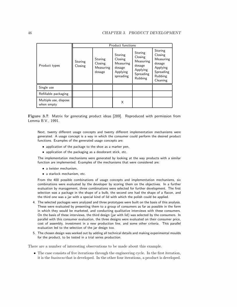
46 CHAPTER 3. PRODUCT DEVELOPMENT
Product functions
Product typesStoringClosing
StoringClosingMeasuringdosage
StoringClosingMeasuringdosageApplyingspreading
StoringClosingMeasuringdosageApplyingSpreadingRubbing
StoringClosingMeasuringdosageApplyingSpreadingRubbingCleaning
Single use
Refillable packaging
Multiple use, disposewhen empty
X
Figure 3.7: Matrix for generating product ideas [289]. Reproduced with permission fromLemma B.V., 1991.
Next, twenty different usage concepts and twenty different implementation mechanisms weregenerated. A usage concept is a way in which the consumer could perform the desired productfunctions. Examples of the generated usage concepts are:
• application of the package to the shoe as a marker pen,
• application of the packaging as a deodorant stick, etc.
The implementation mechanisms were generated by looking at the way products with a similarfunction are implemented. Examples of the mechanisms that were considered are:
• a twister mechanism,
• a starlock mechanism, etc.
From the 400 possible combinations of usage concepts and implementation mechanisms, sixcombinations were evaluated by the developer by scoring them on the objectives. In a furtherevaluation by management, three combinations were selected for further development. The firstselection was a package in the shape of a bulb, the second one had the shape of a flacon, andthe third one was a jar with a special kind of lid with which the polish could be applied.
4. The selected packages were analyzed and three prototypes were built on the basis of this analysis.These were evaluated by presenting them to a group of consumers as far as possible in the formin which they would be marketed, and conducting qualitative interviews with these consumers.On the basis of these interviews, the third design (jar with lid) was selected by the consumers. Inparallel with this consumer evaluation, the three designs were evaluated on their consumer price,cost of assembly, investment in a new production line, and some other criteria. This parallelevaluation led to the selection of the jar design too.
5. The chosen design was worked out by adding all technical details and making experimental mouldsfor the product, to be tested in a trial series production.
There are a number of interesting observations to be made about this example.
• The case consists of five iterations through the engineering cycle. In the first iteration,it is the business that is developed. In the other four iterations, a product is developed.
3.4. PRODUCT ENGINEERING 47
• In all iterations, simulation of some possible actions is performed in order to estimatewhat the likely effects of the action would be. For example, in the first iteration,this simulation was done by the managers by thinking through the best response to abusiness problem using their knowledge of the business and its market.
• Each iteration through the product engineering cycle produces a product specificationof increasing explicitness. The first product engineering iteration (the second of thefive iterations in the example) produces a product idea consisting of a combinationof product type and product function. As explained in chapter 2, a product ideais the underlying idea of what the product is. Having a product idea increases thecoherence and modularity of the product. The final iteration produces a technicalproduct specification and the initial version of a production specification.
• Explicit design objectives to be satisfied by the product are only produced in thesecond of the product engineering iterations. They are stated in such a way that theirachievement or nonachievement by a product is observable. In other words, they arestated in behavioral, operational, measurable terms.
• A final point to notice, which may be of interest to software developers, is that in thesecond iteration through the product engineering cycle (the third of the five iterationsin the example), decisions about the decomposition of the product into componentsare made in parallel with decisions about observable behavior (the “usage concepts”).
Of course, there are some obvious differences between developing a computer-based systemand developing a new kind of packaging for shoe polish. First of all, software is a majorpart of computer-based systems. Software is intangible and many people conclude from thisthat software is very flexible. By contrast, industrial products are tangible and, once theyare produced, everyone can see that they are not very flexible. The problem of changingrequirements, which often occurs in client-oriented development, is therefore even morewidespread in the development of computer-based systems. If requirements changes becometoo frequent or too erratic, then the development cycle will never stop or, if it stops,it will deliver a product that does not meet client needs. This makes the managementof software development considerably more complex than the management of industrialproduct development.
Second, computer-based systems are often closely interwoven with organizational infras-tructures. For example, as observed in chapter 2, an information system can be viewed asan aspect system of a business. All business units interact by exchanging information withother business units and with the business environment. Viewed in this way, the informa-tion system is inextricably bound to the organizational infrastructure. The interweavingbetween organizational infrastructure and computer-based systems becomes even tighterwith EDI systems, which require standardization of business procedures of the connectedbusinesses. This means that the development of those systems is integrated with businessdevelopment, and this in turn makes the complexity of managing the development of acomputer-based system larger than the management of industrial product development.
Despite these differences, an engineer developing a computer-based system iteratesthrough the same engineering method as an industrial designer developing a manufacturingproduct. The rational method of engineering in both kinds of development is the same,even though process attributes like complexity and flexibility differ. Especially noteworthy
48 CHAPTER 3. PRODUCT DEVELOPMENT
is the interleaving of the specification of observable product behavior at one level of aggre-gation, and the specification of the decomposition of the product into parts at a lower levelof aggregation. Above, we saw that this interleaving takes place in the development of suchhumble systems as a packaging for shoe polish.
One last lesson to be learned from the shoe polish packaging example is that rationalproduct development is possible. The engineering cycle is a rational process that does notdeal with mistakes, personnel changes, budget cuts, departmental politics and changingrequirements other than by iterating through the problem solving cycle. As explained inchapter 15, these phenomena are dealt with by process management methods. We willargue there that the engineering cycle is useful as the target structure for a rational recon-struction of the development process, by which the results of development can be justifiedto others. Here, it is important to realize that the engineering cycle is the logical structureof development, not the temporal structure. Its purpose is to allow us to classify tasks indifferent development methods, i.e. to act as a framework for understanding developmentmethods.
3.5 System Modeling
3.5.1 Current system modeling and UoD modeling
There are two tasks in the development of computer-based systems where the developer hasto make a descriptive model of some system. First, in many cases of computer-based systemdevelopment we must make a model of the observable behavior of an existing system. Forexample, in the development of a new version of an information system, we may at sometime have to model that part of the behavior of the current one that must be preserved bythe new one. Current system modeling is often called reverse engineering in computerscience. This is a curious but accurate term, for we will see below that current systemmodeling is the exact opposite of engineering. Reverse engineering is often part of a largerprocess called reengineering, in which a current system must be reimplemented withlargely the same functionality. This is an important development heuristic recommendedby classical structured analysis (chapter 10).
There is a second situation in which the developer must make a model of an existingsystem. We have seen in chapter 2 that computer-based systems have a UoD in which theirdata is interpreted. Developers of computer-based systems must therefore build conceptualmodels of the UoD that can be understood by stakeholders such as implementors and usersof the system.
Finding an accurate and useful conceptual model of the UoD requires expertise of theUoD. In some cases, this expertise is shallow enough to be learned by the system developersthat are not specialists in the UoD. For example, the UoD of a library administration issimple enough to be learned by system developers themselves — but even here they maybump into surprises. Even simpler, the UoD of a pocket calculator requires knowledge ofarithmetic at the primary school level and some simple mathematics at the secondary schoollevel extended with knowledge of finite arithmetic, knowledge which any developer of pocketcalculators can be expected to have. At the other extreme, a decision support system usesa model of its UoD that requires econometric expertise to build and understand. Buildingsuch a model is a profession in its own right and may take a lifetime. The development of

3.5. SYSTEM MODELING 49
decision support systems must therefore involve specialists that have the required econo-metric expertise, as well as software engineers who can cooperate with econometrists inbuilding a decision support system.
3.5.2 The empirical cycle
Whenever a descriptive model of a currently existing system or of a UoD must be made,we should follow the empirical cycle of discovery. Once again, this is a species of therational problem solving cycle. Figure 3.8 shows the structure of the empirical cycle. Thesimilarity with the engineering cycle arises from the fact that both are specializations of therational problem solving method. The difference with the engineering cycle arises from thefact that in engineering we aim at finding a product specification, which is a prescriptivemodel of a product, whereas in the empirical cycle we aim at finding a descriptive model ofan existing part of the world.
Following the empirical cycle, we start from observations and generate one or moremodels that explain the observed phenomena in something called an induction step. Thesemodels are evaluated by deducing observable consequences from them and testing these inexperiments. As a result of these tests, we choose a model or we generate additional modelsthat explain the phenomena. We may even return to the observation task to collect moredata.
Induction is a reasoning form in which, from a finite number of observations, a modelis specified that accounts for these and infinitely many other phenomena. For example,from repeated observation that a physical object expands when heated, we may induce thatany object expands when heated. Induction is logically unsound because it may lead fromtrue premises to a false conclusion. In daily life as well as in science, we must continuouslyjump to conclusions by inducing general models from particular observations.
The unsoundness of induction is a consequence of the fact that any finite set of obser-vations can always be explained by an infinite set of possible models of those observations.Some of these models are true, but most of them are false. For example, if objects a, b andc are observed to expand when heated, we can induce any of the following models:
• All objects expand when heated.
• Most objects expand when heated.
• Some objects expand when heated; others burn immediately.
• Until today, all objects expand when heated, but from tomorrow onwards they willcontract when heated.
• Objects a, b and c expand when heated but all other objects contract when heated.
• Here, all objects will expand when heated; elsewhere, the same objects would contractwhen heated.
We could go on indefinitely. Each of these models is a hypothesis that must be tested bydeducing observable consequences from it, and by testing these consequences in experiments.This leads to confirmations or falsifications. There is an asymmetry between confirmationand falsification that follows from the structure of deduction. Suppose that from hypothesisH we deduce observable consequences O and we do not observe O but something else. Then

50 CHAPTER 3. PRODUCT DEVELOPMENT
Phenomena
Observation
Facts
Induction
Alternative hypothetical models
Deduction
Predictions
Testing
Ranked hypotheses
Choice
Figure 3.8: The empirical cycle.
3.5. SYSTEM MODELING 51
we have falsified H . The reason is that if H → O, then it logically follows that ¬O → ¬H
(here we represent logical implication by → and negation by ¬). On the other hand, if wedo observe that O takes place, then we have not confirmed the truth of H . O follows fromindefinitely other hypotheses as well, and among these other hypotheses there may verywell be better explanations of the phenomena than H .
In practice, confirmation and falsification are not so far apart as suggested here. If theconsequences of H are observed frequently by different people in different circumstances,then our belief in H tends to become very strong. If we strongly believe in H and once in awhile one of H ’s consequences is falsified, then we attribute this to unknown disturbances,measurement errors or other secondary causes, and forget about the falsification. In general,no model can be completely verified or completely falsified by experiments, and we end upwith a ranking of models in order of plausibility, just as in the engineering cycle we end upwith a ranking of product specifications in order of utility.
The following classical example of an application of the empirical cycle is taken fromKemeny [173].
Example of the empirical cycle. In the beginning of the 19th century, Newtonian mechanics
was a well-established body of theory, that had been validated in numerous physical experiments and
astronomical observations. Observations made in the 1820s of the orbit of the then-known outermost
planet, Uranus, revealed a discrepancy between the predictions made by Newton’s theory and the actual
orbit of Uranus. There were several alternatives to explain this discrepancy. For example, Newton’s
theory could be considered refuted, or the observations unreliable. The first option is very unattractive
and the second could be shown to be very implausible. Astronomers therefore generated another
hypothesis, namely that Uranus is not the outermost planet, but that there is a planet beyond it.
The French mathematician Leverrier showed that a planet with a certain size, position and orbit could
account for the aberration between the observed and predicted orbit of Uranus. Using the mathematical
techniques available at that time, this was a considerable feat. In addition, he could predict the position
of this hypothesized planet in the sky. Having deduced these observable consequences, it was relatively
easy for Berlin Observatory to observe the hypothesized planet in the real world, and Neptune was
discovered.
Just as the engineering cycle represents the logical structure of product specification, sothe empirical cycle represents the logical structure of model building. It does not representwhat actually happens during discovery, nor does it represent how scientists think. In theseprocesses, competition between research groups, budget cuts, personnel turnover, mistakes,blunders, blind spots and prejudices all play a role. The study of what happens duringdiscovery is part of the sociology and history of science, and the study of how scientiststhink is part of psychology. The empirical cycle does however show how the resultingmodels must be justified. Scientific publications must present their results as if the empiricalcycle were followed, so that others can reproduce these results, following the same cycle.In chapter 15, we refer to this as a rational reconstruction of the modeling process. Thepurpose of the empirical cycle for us is to act as a framework to understand methods formaking a model of a UoD, not to help the research manager deal with such problems asbudget cuts and personnel turnover. Note the analogy with the engineering cycle, whichcan be used to justify a product specification and to understand engineering methods, butdoes not represent the temporal sequence of engineering tasks.
52 CHAPTER 3. PRODUCT DEVELOPMENT
3.5.3 Comparison of the empirical and engineering cycles
The empirical and engineering cycles are closely related, because both are specializationsof the rational problem solving method. There are also a number of important differencesbetween the two cycles, which all stem from the fact that in engineering we search for aspecification of useful behavior, whereas in modeling we search for a specification of trueknowledge. Of course, it is possible that the engineering cycle leads to new knowledge andthe empirical cycle leads to new technology, but these are secondary products that do notalter the primary aim of following these cycles.
One consequence of this difference is that in the engineering cycle, we are searchingfor a prescriptive model, the product specification, whereas in the empirical cycle we aresearching for a descriptive model. The difference is that in case of a mismatch between aprescriptive model and the modeled product, the product is wrong and the prescription isright. In case of a mismatch between a descriptive model and the modeled part of reality,the model is wrong and modeled reality is right.
Another important consequence of this is that the engineering cycle has a normativeorientation where the empirical cycle has a normatively neutral orientation. The norms bywhich the results of engineering cycle are evaluated are instrumental, i.e. they are normsthat tells us that a particular user need is to be satisfied. The justification of a productalways has the form “because this human desire must be satisfied”. However, it is alwaysmeaningful to ask whether this justification itself is morally sound. Some human desiresmay be immoral in some contexts; and even if they are moral, the means by which they arefulfilled may be immoral. The desire to observe people without being observed is moral insome contexts and immoral others; and the production of cheap products by means of childlabor is immoral in all contexts. Engineering cannot be separated from moral problems.
By contrast, the only norm in the empirical cycle is the norm that true models be found.Even if morally reprehensible behavior is modeled, then the norms by which this behavioris rejected do not play a role in evaluating the outcome of empirical research, which is adescriptive model. A descriptive model is true or false, not morally good or bad. Theempirical researcher should not try to improve the behavior he or she is studying. Bycontrast, the engineer does try to improve the product on which he or she is working.
The empirical researcher must keep a distance from his or her subject in order not todisturb the behavior he or she is modeling. The engineer, on the other hand, is engagedin his or her subject and is committed to improving it in a shared value judgement withthe client. This creates normative problems which may become moral problems. As aresult, professional societies usually set up codes of conduct, which include guidelines forprofessional and moral behavior.
3.6 A Framework for Product Development Methods
A framework for product development methods is a conceptual structure which providesus with points of reference in an analysis of development methods. Viewing the set of alldevelopment methods as the terrain, a framework for development methods provides a gridto be laid upon the terrain. The grid defines reference points that tell us where we areand where we might go to and, importantly, allows us to communicate our current locationand destination to others. Frameworks for development methods usually have a number of
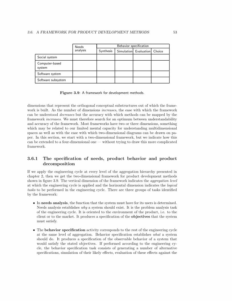
3.6. A FRAMEWORK FOR PRODUCT DEVELOPMENT METHODS 53
Needs Behavior specification
analysis Synthesis Simulation Evaluation Choice
Social system
Computer-basedsystem
Software system
Software subsystem
Figure 3.9: A framework for development methods.
dimensions that represent the orthogonal conceptual substructures out of which the frame-work is built. As the number of dimensions increases, the ease with which the frameworkcan be understood decreases but the accuracy with which methods can be mapped by theframework increases. We must therefore search for an optimum between understandabilityand accuracy of the framework. Most frameworks have two or three dimensions, somethingwhich may be related to our limited mental capacity for understanding multidimensionalspaces as well as with the ease with which two-dimensional diagrams can be drawn on pa-per. In this section, we start with a two-dimensional framework, but we indicate how thiscan be extended to a four-dimensional one — without trying to draw this more complicatedframework.
3.6.1 The specification of needs, product behavior and productdecomposition
If we apply the engineering cycle at every level of the aggregation hierarchy presented inchapter 2, then we get the two-dimensional framework for product development methodsshown in figure 3.9. The vertical dimension of the framework indicates the aggregation levelat which the engineering cycle is applied and the horizontal dimension indicates the logicaltasks to be performed in the engineering cycle. There are three groups of tasks identifiedby the framework:
• In needs analysis, the function that the system must have for its users is determined.Needs analysis establishes why a system should exist. It is the problem analysis taskof the engineering cycle. It is oriented to the environment of the product, i.e. to theclient or to the market. It produces a specification of the objectives that the systemmust satisfy.
• The behavior specification activity corresponds to the rest of the engineering cycleat the same level of aggregation. Behavior specification establishes what a systemshould do. It produces a specification of the observable behavior of a system thatwould satisfy the stated objectives. If performed according to the engineering cy-cle, the behavior specification task consists of generating a number of alternativespecifications, simulation of their likely effects, evaluation of these effects against the
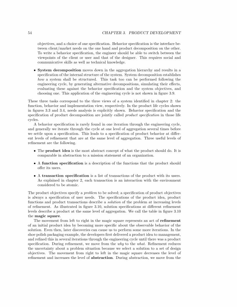
54 CHAPTER 3. PRODUCT DEVELOPMENT
objectives, and a choice of one specification. Behavior specification is the interface be-tween client/market needs on the one hand and product decomposition on the other.To write a behavior specification, the engineer should be able to switch between theviewpoints of the client or user and that of the designer. This requires social andcommunicative skills as well as technical knowledge.
• System decomposition moves down in the aggregation hierarchy and results in aspecification of the internal structure of the system. System decomposition establisheshow a system shall be structured. This task too can be performed following theengineering cycle, by generating alternative decompositions, simulating their effects,evaluating these against the behavior specification and the system objectives, andchoosing one. This application of the engineering cycle is not shown in figure 3.9.
These three tasks correspond to the three views of a system identified in chapter 2: thefunction, behavior and implementation view, respectively. In the product life cycles shownin figures 3.3 and 3.4, needs analysis is explicitly shown. Behavior specification and thespecification of product decomposition are jointly called product specification in those lifecycles.
A behavior specification is rarely found in one iteration through the engineering cycle,and generally we iterate through the cycle at one level of aggregation several times beforewe settle upon a specification. This leads to a specification of product behavior at differ-ent levels of refinement that are at the same level of aggregation. Three useful levels ofrefinement are the following.
• The product idea is the most abstract concept of what the product should do. It iscomparable in abstraction to a mission statement of an organization.
• A function specification is a description of the functions that the product shouldoffer its users.
• A transaction specification is a list of transactions of the product with its users.As explained in chapter 2, each transaction is an interaction with the environmentconsidered to be atomic.
The product objectives specify a problem to be solved; a specification of product objectivesis always a specification of user needs. The specifications of the product idea, productfunctions and product transactions describe a solution of the problem at increasing levelsof refinement. As illustrated in figure 3.10, solution specifications at different refinementlevels describe a product at the same level of aggregation. We call the table in figure 3.10the magic square.
The movement from left to right in the magic square represents an act of refinementof an initial product idea by becoming more specific about the observable behavior of thesolution. Even then, later discoveries can cause us to perform some more iterations. In theshoe polish packaging example, the developers first delivered a product idea to management,and refined this in several iterations through the engineering cycle until there was a productspecification. During refinement, we move from the why to the what. Refinement reducesthe uncertainty about a problem situation because we select a solution to a set of designobjectives. The movement from right to left in the magic square decreases the level ofrefinement and increases the level of abstraction. During abstraction, we move from the
3.6. A FRAMEWORK FOR PRODUCT DEVELOPMENT METHODS 55
Refinement
DecompositionProductobjec-tives
Productidea
Productfunctions
Producttransac-tions
Social system
Computer-basedsystem
Software system
Software subsystem
Figure 3.10: The magic square.
what to the why at the same level of aggregation, i.e. from behavior to function. Becauserefinement is a decomposition of functions into more detailed functions, it is also calledfunction decomposition. It is important not to confuse this with system decomposition,discussed next.
The movements in the vertical dimension are system decomposition moving downand system integration moving up. System decomposition moves from the what at oneaggregation level to the how of that level (which is the what of the next lower level). Justas refinement resolves uncertainty about the behavior that would satisfy system objectives,system decomposition resolves uncertainty about which decomposition would satisfy systemobjectives.
It is worth repeating that the system decomposition dimension is orthogonal to thefunction refinement dimension. There is an important tradition in system design in whichthese dimensions are mapped to each other. This is the tradition of functional systemdecomposition, in which we decompose a system into subsystems that each implement asystem function in such a way that different subsystems implement different functions (at thesame level of refinement). In functional system decomposition, the levels of decompositioncorrespond to levels of refinement. There are however other ways to decompose a systemand in general, system decomposition is orthogonal to function refinement.
Comparing the magic square with figure 3.9, we see that in a rational developmentprocess, a move from a lower to a higher level of refinement (left to right in the square) takesplace according to the engineering cycle. In an actual development process, developmentmay proceed in a less rational way. In general, at any point in the development process,decisions may be made at any level of aggregation and at any level of refinement. Forexample, a particular development process may contain a sequence of decisions as shown infigure 3.11. Each square indicates a level of aggregation and a level of refinement at which adecision was made. A number in a square represents the fact that a decision has been madeat that level of aggregation and refinement, and higher numbers represent later decisions.Occurrences of the number 0 represent the decisions already made before developmentstarted. As illustrated by the placement of numbers in figure 3.11, the progression ofdecisions is not necessarily in the direction of increasing behavior refinement or towards
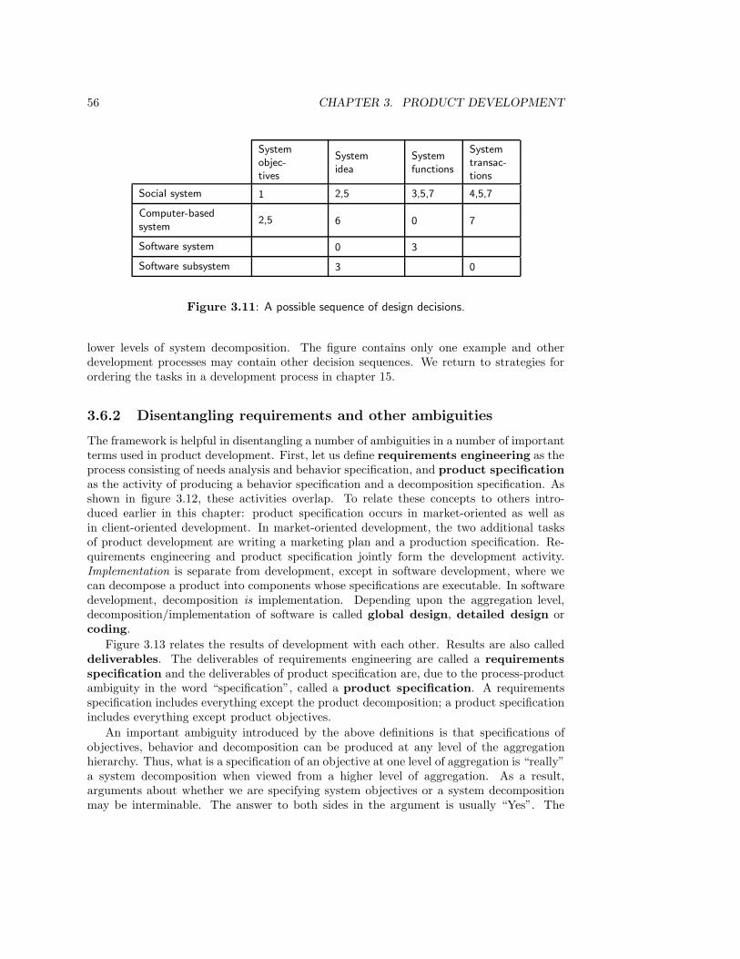
56 CHAPTER 3. PRODUCT DEVELOPMENT
Systemobjec-tives
Systemidea
Systemfunctions
Systemtransac-tions
Social system 1 2,5 3,5,7 4,5,7
Computer-basedsystem
2,5 6 0 7
Software system 0 3
Software subsystem 3 0
Figure 3.11: A possible sequence of design decisions.
lower levels of system decomposition. The figure contains only one example and otherdevelopment processes may contain other decision sequences. We return to strategies forordering the tasks in a development process in chapter 15.
3.6.2 Disentangling requirements and other ambiguities
The framework is helpful in disentangling a number of ambiguities in a number of importantterms used in product development. First, let us define requirements engineering as theprocess consisting of needs analysis and behavior specification, and product specificationas the activity of producing a behavior specification and a decomposition specification. Asshown in figure 3.12, these activities overlap. To relate these concepts to others intro-duced earlier in this chapter: product specification occurs in market-oriented as well asin client-oriented development. In market-oriented development, the two additional tasksof product development are writing a marketing plan and a production specification. Re-quirements engineering and product specification jointly form the development activity.Implementation is separate from development, except in software development, where wecan decompose a product into components whose specifications are executable. In softwaredevelopment, decomposition is implementation. Depending upon the aggregation level,decomposition/implementation of software is called global design, detailed design orcoding.
Figure 3.13 relates the results of development with each other. Results are also calleddeliverables. The deliverables of requirements engineering are called a requirementsspecification and the deliverables of product specification are, due to the process-productambiguity in the word “specification”, called a product specification. A requirementsspecification includes everything except the product decomposition; a product specificationincludes everything except product objectives.
An important ambiguity introduced by the above definitions is that specifications ofobjectives, behavior and decomposition can be produced at any level of the aggregationhierarchy. Thus, what is a specification of an objective at one level of aggregation is “really”a system decomposition when viewed from a higher level of aggregation. As a result,arguments about whether we are specifying system objectives or a system decompositionmay be interminable. The answer to both sides in the argument is usually “Yes”. The
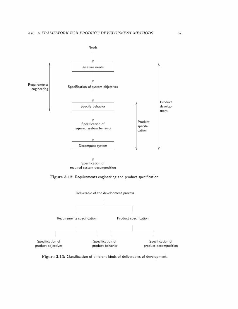
3.6. A FRAMEWORK FOR PRODUCT DEVELOPMENT METHODS 57
Needs
Analyze needs
Specification of system objectives
Specify behavior
Specification ofrequired system behavior
Decompose system
Specification ofrequired system decomposition
Requirementsengineering
Productspecifi-cation
Productdevelop-ment
Figure 3.12: Requirements engineering and product specification.
Deliverable of the development process
Requirements specification Product specification
Specification ofproduct objectives
Specification ofproduct behavior
Specification ofproduct decomposition
Figure 3.13: Classification of different kinds of deliverables of development.
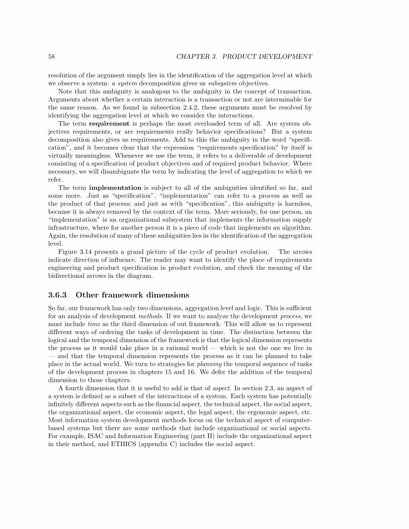
58 CHAPTER 3. PRODUCT DEVELOPMENT
resolution of the argument simply lies in the identification of the aggregation level at whichwe observe a system: a system decomposition gives us subsystem objectives.
Note that this ambiguity is analogous to the ambiguity in the concept of transaction.Arguments about whether a certain interaction is a transaction or not are interminable forthe same reason. As we found in subsection 2.4.2, these arguments must be resolved byidentifying the aggregation level at which we consider the interactions.
The term requirement is perhaps the most overloaded term of all. Are system ob-jectives requirements, or are requirements really behavior specifications? But a systemdecomposition also gives us requirements. Add to this the ambiguity in the word “specifi-cation”, and it becomes clear that the expression “requirements specification” by itself isvirtually meaningless. Whenever we use the term, it refers to a deliverable of developmentconsisting of a specification of product objectives and of required product behavior. Wherenecessary, we will disambiguate the term by indicating the level of aggregation to which werefer.
The term implementation is subject to all of the ambiguities identified so far, andsome more. Just as “specification”, “implementation” can refer to a process as well asthe product of that process; and just as with “specification”, this ambiguity is harmless,because it is always removed by the context of the term. More seriously, for one person, an“implementation” is an organizational subsystem that implements the information supplyinfrastructure, where for another person it is a piece of code that implements an algorithm.Again, the resolution of many of these ambiguities lies in the identification of the aggregationlevel.
Figure 3.14 presents a grand picture of the cycle of product evolution. The arrowsindicate direction of influence. The reader may want to identify the place of requirementsengineering and product specification in product evolution, and check the meaning of thebidirectional arrows in the diagram.
3.6.3 Other framework dimensions
So far, our framework has only two dimensions, aggregation level and logic. This is sufficientfor an analysis of development methods. If we want to analyze the development process, wemust include time as the third dimension of out framework. This will allow us to representdifferent ways of ordering the tasks of development in time. The distinction between thelogical and the temporal dimension of the framework is that the logical dimension representsthe process as it would take place in a rational world — which is not the one we live in— and that the temporal dimension represents the process as it can be planned to takeplace in the actual world. We turn to strategies for planning the temporal sequence of tasksof the development process in chapters 15 and 16. We defer the addition of the temporaldimension to those chapters.
A fourth dimension that it is useful to add is that of aspect. In section 2.3, an aspect ofa system is defined as a subset of the interactions of a system. Each system has potentiallyinfinitely different aspects such as the financial aspect, the technical aspect, the social aspect,the organizational aspect, the economic aspect, the legal aspect, the ergonomic aspect, etc.Most information system development methods focus on the technical aspect of computer-based systems but there are some methods that include organizational or social aspects.For example, ISAC and Information Engineering (part II) include the organizational aspectin their method, and ETHICS (appendix C) includes the social aspect.
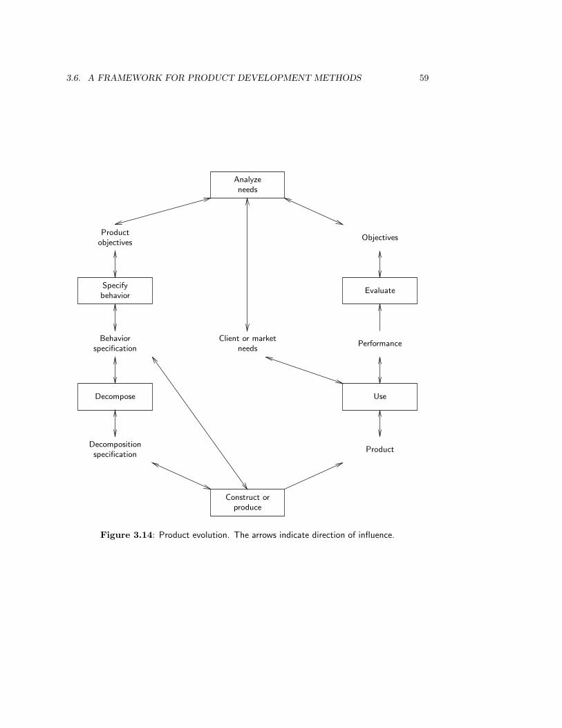
3.6. A FRAMEWORK FOR PRODUCT DEVELOPMENT METHODS 59
Analyzeneeds
Productobjectives
Specifybehavior
Behaviorspecification
Decompose
Decompositionspecification
Construct orproduce
Product
Use
Performance
Evaluate
Objectives
Client or marketneeds
Figure 3.14: Product evolution. The arrows indicate direction of influence.
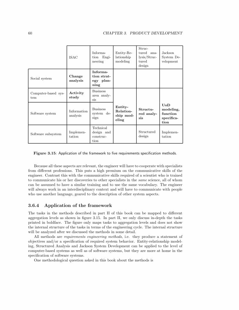
60 CHAPTER 3. PRODUCT DEVELOPMENT
ISAC
Informa-tion Engi-neering
Entity-Re-lationshipmodeling
Struc-tured ana-lysis/Struc-tureddesign
JacksonSystem De-velopment
Social systemChangeanalysis
Informa-tion strat-egy plan-ning
Computer-based sys-tem
Activitystudy
Businessarea analy-sis
Software systemInformationanalysis
Businesssystem de-sign
Entity-Relation-ship mod-eling
Structu-red analy-sis
UoDmodeling,functionspecifica-tion
Software subsystemImplemen-tation
Technicaldesign andconstruc-tion
Structureddesign
Implemen-tation
Figure 3.15: Application of the framework to five requirements specification methods.
Because all these aspects are relevant, the engineer will have to cooperate with specialistsfrom different professions. This puts a high premium on the communicative skills of theengineer. Contrast this with the communicative skills required of a scientist who is trainedto communicate his or her discoveries to other specialists in the same science, all of whomcan be assumed to have a similar training and to use the same vocabulary. The engineerwill always work in an interdisciplinary context and will have to communicate with peoplewho use another language, geared to the description of other system aspects.
3.6.4 Application of the framework
The tasks in the methods described in part II of this book can be mapped to differentaggregation levels as shown in figure 3.15. In part II, we only discuss in-depth the tasksprinted in boldface. The figure only maps tasks to aggregation levels and does not showthe internal structure of the tasks in terms of the engineering cycle. The internal structurewill be analyzed after we discussed the methods in some detail.
All methods are requirements engineering methods, i.e. they produce a statement ofobjectives and/or a specification of required system behavior. Entity-relationship model-ing, Structured Analysis and Jackson System Development can be applied to the level ofcomputer-based systems as well as of software systems, but they are more at home in thespecification of software systems.
One methodological question asked in this book about the methods is
3.7. SUMMARY 61
• How can we map the tasks recommended by the methods to the engineering cycle?
Because all studied methods are methods for specifying the behavior of computer-basedsystems, and these systems have a UoD, there is an additional question to be answered:
• How does the method mix UoD modeling with the specification of required systemfunctions?
It will be shown that Entity-Relationship modeling is primarily a method for finding aconceptual model of the UoD, whereas Structured Analysis does not distinguish a conceptualmodel of the UoD from a system model. Jackson System Development is unique in makinga clear distinction between conceptual model of the UoD and a specification of requiredsystem behavior.
The two questions above are about the tasks to be performed in requirements specifi-cation process. Two other important questions to be asked concern the structure of thespecifications produced when the methods are followed:
• What is the structure of system specifications produced by the methods?
• Can the specifications produced by different methods be integrated?
We will answer these questions in detail for the software system specification methods. Asa preparation, we look at the structure of product specifications in general in the nextchapter.
3.7 Summary
Product development is a process that, given a need, delivers a specification of a solutionthat is expected to satisfy this need. In client-oriented development, the need is felt by asingle client, in market-oriented development, the need is identified to exist in a market.Client-oriented development produces a specification of an an individual product, whereasmarket-oriented development produces a marketing plan, a product specification and aproduction specification. In both cases, we can identify a number of stakeholders in the de-velopment process. The development organization is the person or organization performingthe development process. The sponsor pays for the development process, the customer buysthe delivered product, and the user uses the product. In client-oriented development, thesponsor and customer are identical. The client may be the sponsor, customer or user of theproduct.
All products evolve, because when they are used, the needs of the user change and theenvironment of uses changes as well. In client-oriented development, the needs of the clientmay even change because of the determination of objectives. This is called requirementsuncertainty. The characteristic feature of product evolution is that an evaluation of ex-perience of the product after it is developed, leads to a (re)development of the product.The logical structure of product evolution is the same as the logical structure of feedbackcontrol, viz. the regulatory cycle.
In product engineering, a product specification is produced by means of a rational prob-lem solving process. The essence of this process is that the effects of alternative specificationsare simulated and evaluated before the specification is implemented. This evaluation maylead to a new iteration through the engineering process until the desired effects are found.
62 CHAPTER 3. PRODUCT DEVELOPMENT
The empirical cycle is a rational problem solving process in which a true model ofobserved phenomena is sought. The essence of this process is the experimental evaluationof alternative models of the phenomena. The empirical cycle is a useful method for currentsystem modeling as well as for conceptual modeling.
The engineering and empirical cycles are applications of the rational problem solvingcycle and are not methods for planning the development or modeling process. They canhowever be used as targets for a rational reconstruction of the process after the fact, usedfor justifying the results of the processes.
The empirical and engineering cycles are closely parallel in their form, but they havea few fundamental differences. The empirical cycle is a search for knowledge, but theengineering cycle is a search for the satisfaction of requirements. The empirical cycle istherefore value-free in the sense that it does not pass judgement on the subject of study.The engineering cycle is normative in the sense that the engineer continually passes valuejudgements on the subject of study, viz. how well the behavior satisfies the objectives ofthe development process. Related to this difference is the fact that the empirical scientistis an observer with a detached attitude with respect to his or her subject of study, but thatthe engineer is involved in his or her subject. The engineer is an actor in the world, not anobserver of the world. As a consequence, the engineer may be engaged in situations thatraise moral questions. There are codes of conduct that provide guidelines for professionaland moral behavior.
If we combine the levels of aggregation identified in the previous chapter with the en-gineering cycle, we get a framework that can be used to classify development methods. Inthis framework, requirements engineering consists of two tasks, needs analysis and behav-ior specification. Product specification is the partly overlapping task consisting of behaviorspecification and product decomposition. Market-oriented development consists of needsanalysis, product specification, production specification and marketing; client-oriented de-velopment consists of needs analysis and product specification.
The development framework is not a strategy to plan the development process. Timewould be a third dimension of the framework, orthogonal to the partitioning in aggrega-tion levels and to the logical tasks of product development. A fourth dimension would beaspect. Important system aspects that may have to be subject of development include theorganizational, social, ergonomic, and legal aspects.
3.8 Exercises
1. For each of the following development processes, identify the client(s), sponsor(s),customer(s), and user(s).
(a) The development of air traffic control software which, by law, must be installedon board of airplanes by the aircraft builder.
(b) The development of a new version of a database management system (DBMS)by a vendor of database software.
(c) The development of parametrized software for the administration of documentcirculations.
(d) The development of software to register military conscripts.

3.8. EXERCISES 63
2. This question is about the TANA case study.
(a) What kind of simulations are performed in each of the iterations through theengineering cycle?
(b) How are the evaluations of the simulation results performed?
3. Loucopoulos and Karakostas [198] define requirements engineering as the transforma-tion of business concerns into software system requirements. They present a frame-work in which requirements engineering is decomposed into the following three inter-acting processes, that are performed in parallel with each other:
• Requirements elicitation: reaching an understanding of the problem. Sourcesof requirements knowledge are identified and their relevance and significanceestimated.
• Requirements specification: describing the problem. In this process, the ac-quired knowledge is analyzed and organized into a coherent requirements model.A series of conceptual models is produced that represent the problem domain.The conceptual models in the series become increasingly refined, and increasinglyrepresent the software domain instead of the problem domain.
• Requirements validation: ensure that the requirements model agrees withthe user’s expectations. In this process, experiments are prepared, performedand the results of experiments evaluated.
Compare these tasks with the framework for development of figure 3.9.
4. Nadler [238] observed the problem solving processes of an engineer, a commercialartist, an architect, a physician and a lawyer and found following common structure:
(a) Determine the function of the required system.
(b) Develop a number of very high level versions of the required system. Evaluatethem and select one.
(c) Gather information necessary to continue the design.
(d) Generate alternative systems on the basis of the abstract ideal and the informa-tion gathered.
(e) Select the feasible solution.
(f) Specify the chosen solution.
(g) Subject the selected solution to internal and external review.
(h) Test the system design.
(i) Install the system.
(j) Measure the performance of the system.
Map this process to the regulatory cycle.
5. Verification by testing cannot show the correctness of an implementation, but canshow its incorrectness. Compare this with the fact that experiments can falsify ahypothesis but cannot prove it to be true.
64 CHAPTER 3. PRODUCT DEVELOPMENT
6. In the discovery of Neptune, one induction step took place. Identify this step.
7. Dewey [86, pages 107-115] defines what he calls the process of reflective thinking asfollows:
(a) Suggestions of alternatives for action. This is the first moment at which webecome aware of a problem. Direct, unreflective action is inhibited and thehesitation and delay necessary for reflective thinking arises.
(b) Intellectualization of the situation, in which the conditions that constitute thetrouble and cause the stoppage of action are investigated.
(c) A hypothesis about what to do “springs up” to the mind and is formulated.
(d) Reasoning about the possible consequences of the hypothesis.
(e) Testing the hypothesis by action.
Compare this with the method of rational problem solving discussed in this chapter bycorrelating each task in Dewey’s method with task(s) in the rational problem solvingcycle. In addition, indicate a relationship with the regulatory cycle.
8. Kolb and Frohman [184] define the process of planned change, to be followed byorganization consultants, as follows.
(a) Scouting: the consultant and the organization explore a potential relationshipwith the other.
(b) Entry: Negotiate a contract.
(c) Diagnosis: The consultant analyses the problem of the client, the objectives ofthe client, the resources of the client and the resource of the consultant.
(d) Planning: Generate alternative solutions or change strategies and simulate theconsequences of each plan.
(e) Action: Implement the best action.
(f) Evaluation: Evaluate the results of the change efforts.
(g) Termination: Terminate the contract between the consultant and the client or-ganization.
Compare this with the engineering method discussed in this chapter by correlatingeach task in Kolb and Frohman’s method with task(s) in the engineering cycle. Isthere also a similarity with the regulatory cycle?
9. The arrows in figure 3.14 indicate direction of influence. For each arrow, give anexample of a case where influence goes in the indicated direction(s).
3.9 Bibliographical Remarks
Rational problem solving The model of rational problem solving used in this chaptergoes back to a proposal by Dewey [86, pages 107-115], used in exercise 7 above. A simplifiedversion of Dewey’s proposal was adopted by Simon [315, 316]. This model has been very

3.9. BIBLIOGRAPHICAL REMARKS 65
influential in artificial intelligence, where it took the shape of means-ends analysis [318] andwas implemented in the General Problem Solver (GPS) [97].
The rational problem solving method has been recognized to be useful by managementscientists and consultants too. For example, in a famous descriptive study of 25 strategicdecision processes in organizations, Mintzberg, Raisinghani and Theoret [234] found thatthe rational problem solving method serves as a useful framework to understand whatmanagers do. Managers do not blindly follow through this process step by step, but choosea path through it that may skip tasks that are easy or for which there is no time, and thatmay iterate over tasks that are important for the problem at hand.
As a second example, Kolb and Frohman [184] define the process of planned change, tobe followed by organization consultants, as a rational problem solving cycle (see exercise 8above).
Against this prevalence of rational problem solving methods one can observe that oftenthe time to generate all alternatives, or the information to investigate their consequences,are not available. Simon [315] proposed the model of bounded rationality, in which only somealternatives are investigated, using the resources available. Secondly, March and Olsen [211]remark that rational problem solving in organizations presupposes that different people havethe same preferences and that these preferences can be specified before the choice is made.Both presuppositions are often not satisfied. As an alternative model for organizationaldecision making they propose the garbage can model of organizational choice, in which anorganization is viewed as a sea in which problems, solutions and people float around andoccasionally meet each other. When the three meet and the organization is expected tobehave in a way that is called “making a choice”, some people that happen to be aroundconnect solutions that happen to be available with problems they find themselves confrontedwith. This model is not suitable to use as a basis for planning product development, but itmay help the manager of the development process to understand some of the things goingon inside and around the development process.
The engineering cycle. The engineering cycle used in this chapter is based upon amodel of the decision cycle in engineering design given by Roozenburg and Eekels [289] andby Hall [131]. Additional explanations of the engineering cycle are given by Asimov [15],Jones [169] and Archer [13]. Pugh [276] shows how these ideas can be implemented in aprocess for integrated product engineering. Archer [11] shows how the product developmentprocess is embedded in the larger process of product innovation (viewed in this chapter as aspecies of product evolution). The example of the development of a new kind of packagingfor shoe polish is taken from Roozenburg and Eekels [289].
Software engineering. Peters [257] uses some of the insights from industrial design todefine a framework for software engineering methods. Jensen and Tonies [165] analyze thesoftware engineering process from a general engineering standpoint as a problem solvingprocess and come up with a model of the engineering cycle similar to the one presented inthis chapter.
The view that software engineering should be an engineering discipline is supported byD.M. Berry in a report for the Software Engineering Institute [30]. However, Berry ignoresor at least underplays the role of simulation in engineering before implementation. Hequotes Koen [183] in defining engineering as the strategy for causing the best change in a
66 CHAPTER 3. PRODUCT DEVELOPMENT
poorly understood situation with the available resources, and he then quotes an unpublisheddefinition of Mary Shaw and Watts Humphrey that software engineering is “that formof engineering that applies computer science and mathematics to achieving cost-effectivesolutions to software problems”. In this definition, software engineering is problem solving,but the use of simulation and evaluation before the software product is implemented, is notmentioned. Baber [17] takes the same view of engineering as we do and emphasizes the useof scientific knowledge and principles in the computation of product properties before theproduct is actually built. Consequently, he doubts whether software engineering currentlyis really an engineering discipline.
Although software engineering, if it is to fulfill the promise of its name, can learn fromproduct engineering, there are nevertheless some fundamental differences between softwareengineering and product engineering. In a famous position paper published in 1985, Par-nas [254] argues that due to discrete state-changing behavior and complexity, software isinherently unreliable. Software engineering, formal methods and artificial intelligence tech-niques may provide some help to master the complexity of software, but will do so only insmall increments. In an equally famous paper that appeared two years later, Brooks [53]lists four essential differences between industrial product development and software deve-lopment, that make the engineering of software essentially hard: the complexity, invisibility,and changeability of software when compared to other products, and the intertwining ofsoftware with other products. Because of this intertwining, software must conform to alarge number of requirements imposed upon it by these other products. In a reaction tothese papers, Harel [138] provides a more optimistic view by arguing that system modeling,visual languages and model execution may provide the means to tackle some of these prob-lems. We may observe that modeling a system before it is built and executing the modelto evaluate it, both proposed by Harel, are part of the essence of the engineering methodas defined in this chapter.
Empirical cycle. The empirical cycle is described in any introductory textbook on thephilosophy of science. Classic statements are given by Kemeny [173] and Nagel [239]. Theobservation that hypotheses can only be falsified, not verified, comes from Popper [264].Popper’s falsification theory corresponds with Dijkstra’s [87] famous observation that testscan only show the presence of bugs in a program, not their absence. The comparisonof the engineering cycle and empirical cycle is based on an analysis of the logic of socialaction given by van Strien [329] and on a comparison of the two cycles by Roozenburg andEekels [289].
Codes of conduct. Codes of conduct relevant for engineering computer-based systemsare the ACM Code of Professional Conduct [2] and the IEEE Code of Ethics [154]. Andersonet al. [9] illustrate the use of the ACM code in decision making. There are now several bookson ethical aspects of decision making in computer-based system development, includingJohnson [167], Ermann, Williams and Guttierez [96] and Forester and Morrison [106].
Needs analysis. Needs analysis is the most difficult task in the entire development pro-cess. Mistakes made here have the most expensive consequences. The problem to be solvedat this stage is not to find a solution to the requirements; it is to find out what the ob-jectives of the product are [12], and this is a wicked problem. According to Rittel and
3.9. BIBLIOGRAPHICAL REMARKS 67
Webber [279], wicked problems have no definitive formulation, and the solution is deter-mined to a large extent by the formulation of the problem. Wicked problems do not have asolution space that can be enumerated or even described, and once we start analyzing them,we always find they are symptoms of other problems. There is no criterion to determinethe quality of solutions and the problem solving process has no stopping rule. Whatever weaccept as a solution is not true or false, it is good or bad. Wicked problems are unique, andthey are so urgent that the problem solver cannot afford to be wrong. There is no occasionto try a solution first and implement it later; every trial solution counts as an irreversiblestep in real life. In other words, a wicked problem is a real problem.
Given this predicament, one may wonder what to do. In a delightful little book, Gauseand Weinberg [112] give a number of important hints on how to go about solving realproblems. In a more extensive treatment [111], they give numerous practical methods andtechniques by which to tackle problems in needs analysis. Gause and Weinberg argue thatwe can never know what the client’s needs are and that requirements determination is allabout determining the client’s desires. As defined in chapter 2, user needs are user desires,so in the terminology of this book, needs analysis is the determination of the client’s desires.A survey of experimental techniques for needs analysis is given by Gutierrez [129]. Byrd,Cossick and Zmud [55] give a synthesis of techniques for needs analysis and knowledgeacquisition. Jones [168] gives a very interesting survey of techniques for different stages inproduct development, including needs analysis.
Requirements uncertainty. The principle of requirements uncertainty has been calledthe uncertainty principle of data processing by James Martin and Clive Finkelstein [217]and by McCracken and Jackson [221] and Heisenberg-like uncertainty by Lehman [191]. Theessence of this uncertainty is that by installing and using a product, needs tend to changeso that the product tends to become obsolete by being used.
Behavior specification. An early survey of behavior specification techniques (also calledrequirements specification techniques) was given by Taggart and Tharp [336]. In the sameyear, Ross and Schoman [294] published a classic paper on the specification of requiredsystem behavior, that is full of insights in the requirements engineering process. The dis-tinction between function, observable behavior and structure (why, what and how), whichis one of the structuring themes of this book, is already made in this paper.
Davis [77] gives a survey of techniques which uses roughly the same classification of tech-niques as we do here, viz. problem analysis (called objectives determination here) and re-quirements specification (called behavior specification here). However, Entity-Relationshipmodeling, Data Flow modeling and Jackson System Development are treated as problemanalysis methods by Davis and as behavior specification methods in this book. This isexplained by the fact that we focus on computer-based systems, whereas Davis focuses onsoftware systems, which is one level lower in the aggregation hierarchy. What is behaviorspecification for a computer-based system is objectives determination, and hence problemanalysis, for a software system.
Requirements engineering. There are a number of good surveys of issues in require-ments engineering. Curtis, Krasner and Iscoe [74] report on an empirical study of softwareproduct development processes that the major problems in these processes are the thin

68 CHAPTER 3. PRODUCT DEVELOPMENT
spread of application knowledge, changing and conflicting requirements, and communica-tion and coordination breakdowns. The first two of these problems concern the requirementsengineering task. Dorfman [89] gives a brief introduction to requirements engineering at thelevel of computer-based systems and of software systems and shows how requirements flowdown from one level to the next. Stokes [326] gives a survey of the problems with require-ments engineering, possible solutions to these problems, and methods and techniques for thespecification of required system behavior. Brackett [50] gives an interesting survey of thesubfields of requirements engineering in the form of a curriculum outline and an extensiveannotated bibliography. Yeh and Ng [373] give a brief survey of methods and techniquesfor specifying requirements. They emphasize the need for specifying the environment of theproduct in addition to specifying the properties required of the product. In an interestingstudy by Lubars, Potts and Richter [199] of requirements engineering in ten organizations,it was found that most problems of requirements engineering in practice are organizational,and that organizational solutions to technical problems were sought. Examples of problemsthat exist in practice are poor interactions between developers and users, lack of guidancein finding a product specification, problems in specifying product objectives, and changingrequirements. Hsia, Davis and Kung [149] suggest a number of research directions to tacklethese issues, such as animation of specifications, computer-aided requirements engineeringand method integration.
It is clear that interest in requirements engineering is rapidly rising. In 1991, a spe-cial issue of the IEEE Transactions on Software Engineering was devoted to requirementsengineering [79] and in 1993 a two-yearly conference on requirements engineering [102]was started. The March 1994 issue of IEEE Software includes some papers from the firstconference in this series [80]. Starting from 1996, Springer will publish the Requirements En-gineering Journal. In addition to Davis’ book [77] on software requirements specifications,there is now a textbook by Loucopoulos and Karakostas on requirements engineering [198].This book gives a useful survey of techniques and heuristics for elicitation, modeling, andvalidation of system requirements.
Frameworks. There are numerous framework for system development. The frameworkdefined in figure 3.9 has two dimensions, logic and aggregation level. In an influential paper,Hall [132] defines a framework with three dimensions: logic (problem solving procedure),time (problem solving process) and aspect (kind of knowledge of the developed system). Thelogic dimension is virtually the same as the logic dimension of our framework. Hall’s timedimension is introduced in chapter 15, when we look at strategies to perform the actualsystem development process. A two-dimensional logic-time framework, corresponding totwo of Hall’s three dimensions, is now well-accepted in software engineering [222, 287, 240],but to my knowledge, no reference is made in the software engineering literature to Hall’sframework. The term “magic square” comes from Harel and Pnueli [140], but they do notmention the particular levels of refinement and decomposition that I use. They give a clearargument for the importance of the magic square in understanding system development.
Roman, Stucki, Ball and Gillett [286] define a framework for system development thatuses an aggregation hierarchy too. At each level of the hierarchy, a sequence of tasks isdefined that can be construed as a division of requirements determination and conceptualmodeling into subtasks, and a merging of the resulting steps.
Davis [76] gives a framework that resembles the one used in this book. Davis’ frameworkconsists of an aggregation dimension and a logical dimension. However, he focuses on
3.9. BIBLIOGRAPHICAL REMARKS 69
one aggregation level only, that of software product development, and he does not usethe engineering cycle as a logical task structure at each level of aggregation. Rather, hedistinguishes user needs analysis, solution space definition, external behavior definition andpreliminary design as logical tasks at one level. In terms of our framework, these would bethe result of successive iterations through the engineering cycle at one level of aggregation.
The frameworks discussed so far are method-oriented. They try to classify tasks in thedevelopment process. Some frameworks are specification-oriented, i.e. they are based on aclassification of the intermediary or final specifications produced. An example is Blum’s [34]framework, which distinguishes problem oriented from product oriented specifications alongone dimension, and semi-formal and formal representations on the other. Pohl [259] distin-guishes three specification dimensions: (in)completeness of the specification, (in)formalityof the specification and (dis)agreement about the specification.
When we turn to frameworks for information system development methods, we find awide variety, most of them oriented towards what aspect of the UoD is represented. Manyof these are published in the proceedings of the conferences on Comparative Research inInformation Systems (CRIS) [248, 247, 249]. These frameworks can best be understoodas frameworks for UoD models, and should be compared with the modeling frameworkdiscussed in chapter 13.

Chapter 4
Requirements Specifications
4.1 Introduction
A requirements specification consists of a specification of product objectives and a specifi-cation of required product behavior. In this chapter, we discuss the structure of a specifi-cation of product objectives (section 4.2), classify different kinds of behavior specifications(section 4.3) and give a simple framework for the structure of behavior specifications (sec-tion 4.4). In section 4.5, we list a number of desirable properties of requirements specifica-tions.
4.2 Product Objectives
The generic objective of any product is to answer needs that exist in its environment. Anydevelopment process starts with a statement of product objectives and produces behaviorspecifications and product decompositions along the way. As explained in chapter 3, whatis a decomposition from one point of view is part of the objectives at the next lower level ofaggregation. It is therefore useful to distinguish the top level objectives identified as the re-sult of a needs analysis from lower level objectives. Figure 4.1 clarifies the situation. At eachlevel below that of the top level objectives, the behavior specification and decompositionspecification are the objectives for systems at the next lower level of aggregation.
An example top level objective in the TANA case study (chapter 3) was to maintainTANA’s market share. The output of the first iteration through the engineering cycle inthat example was the decision to develop a new product for the current market of TANA.This output then became the objective to be realized in the ensuing development process(figure 4.1). The product specification was then written in a number of iterations thatstayed at the same level of aggregation. For example, in the second iteration, a productidea was delivered as initial product specification. This became the objective of the thirditeration through the engineering cycle, in which a concept of operation was produced, etc.
Example top level objectives identified in the library case study of ISAC change analysisin chapter 5 are the improvement of acquisition procedures and the improvement of returnprocedures of the library. In all cases, top level objectives are the translation of client ormarket needs into objectives to be achieved by the product under development.
71
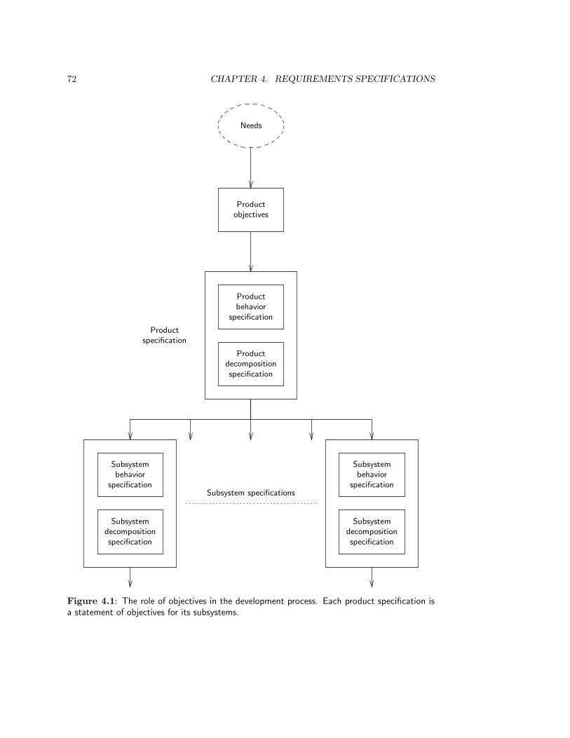
72 CHAPTER 4. REQUIREMENTS SPECIFICATIONS
Needs
Productobjectives
Productbehavior
specification
Productdecompositionspecification
Productspecification
Subsystembehavior
specification
Subsystemdecompositionspecification
Subsystembehavior
specification
Subsystemdecompositionspecification
Subsystem specifications
Figure 4.1: The role of objectives in the development process. Each product specification isa statement of objectives for its subsystems.
4.3. BEHAVIOR AND PROPERTY SPECIFICATIONS 73
It is common to distinguish objectives from constraints that the product must satisfy.The difference between objectives and constraints is however more in the eye of the beholderthan in the objectives or constraints themselves. Both are norms that the product mustsatisfy. The difference seems to be that limitations on the solution space, imposed fromthe outside, are experienced by some developers as constraints on their design freedom.By contrast, goals worth striving for, peaks of achievement to be realized by the choicesthat the developer makes, are viewed by those developers as objectives. This distinction iswholly subjective, and in what follows the term “constraint” is used as a stylistic variantof “objective”.
4.3 Behavior and Property Specifications
We can specify product behavior at different levels of refinement. We saw in subsection 3.6that the following three levels are useful in practice:
• The product idea is the most abstract specification of what the product should do.
• A function specification is a description of the functions that the product shouldoffer its users.
• A transaction specification is a list of transactions of the product with its users.
In subsection 2.4.4, we saw that aspects of product behavior can be summarized by productproperties. At the level of abstraction of the product idea or that of required systemfunctions, it is often not possible to specify properties behaviorally. Once we are ableto specify required product transactions, we should also be able to specify most requiredproduct properties in a behavioral way. For properties for which we cannot find a behavioralspecification, we should try to find proxies, whose presence can be behaviorally specifiedand that suggest the presence of the desired property. Indeed, decreasing the abstractionlevel from product idea to product transaction, we often replace a high level desired productproperty by lower level proxies for that property.
A behavioral specification of a property describes an experiment in which evidence isgiven for the presence or absence of the property. This experiment can be described atvarious levels of detail. For example, we can represent user-friendliness by the proxies thatthe average initial training time needed by all users must be short and that the number ofhelp requests about the system must be low. These observation procedures must be mademore precise by indicating how users are sampled, or over which period they are observed,what is the size of the user population over which we average help requests, etc. To keepthe main flow of ideas in a specification clear, we should write a global specification of theproperty first and add measuring procedures later as footnotes [111, page 172].
There are a number of checklists of kinds of properties that a software system can have.Figure 4.2 gives one such list. Correctness is a meta-property, for it indicates the degreeto which the product satisfies its (other) properties. Security is an example of a negativeproperty, because it is about something that should not be observed. An example of asecurity property is the property that unauthorized access cannot occur. Other examples ofnegative properties are absence of deadlock, absence of collisions in a robot control systemand, more generally, absence of unsafe behavior. Examples of positive properties are that asystem should cost less than Dfl 10 to the customer and that it should have a response time

74 CHAPTER 4. REQUIREMENTS SPECIFICATIONS
• Correctness: The extent to which the product satisfies the objectives.
• Reliability: The extent to which the product behaves as specified in different circum-stances.
• Efficiency: The amount of resources needed by the product.
• Security: The extent to which unauthorized use of the product can be prevented.
• User-friendliness: The ease of use of the product.
• Maintainability: The ease with which product malfunction can be repaired.
• Testability: The ease with which the product can be ascertained to conform to itsspecification.
• Flexibility: The ease with which the product can be modified after delivery, so that itconforms to a changed specification.
• Portability: The ease with which the product can be ported from one hardware andsoftware environment to another.
• Reusability: The ease with which components of the product can be used in otherproducts.
• Interoperability: The ease with which the product can interface to other products.
Figure 4.2: Kinds of software product properties.
of less than 2 seconds. It is much harder to specify an observation procedure for negativeproperties than for positive properties. Experimental verification that a product satisfies anegative property would require observation of the product throughout its complete lifetime.Obviously, such an experiment is too expensive and is useless — we would like to verify theproperty before the product is used, not after it is disposed of. A convincing verification ofthe presence of a negative property in a product must take the form of a mathematical orlogical proof that the unwanted behavior cannot occur.
Different required properties may conflict with each other. In case of conflict, the en-gineer must perform trade-off studies, and to perform these studies, it is desirable thatrequired properties be specified in the form of preferences for certain properties aboveothers. A minimal indication of preferences is a distinction between essential propertiesthat the product must have, and desired properties that it would be nice to have. A morerefined specification would give an ordering of all possible property values in order of pref-erence. For example, preferences of the market for washing machines may be such that anoise level of 0 dB has the highest preference and 9 dB the lowest. A noise level of 0 dB maybe achievable at a very high price by using expensive state-of-the-art anti-noise technology,and the market also happens to have a preference for cheap washing machines. As a result,the marketing department adjusts its preferences and settles on an acceptable combinationof noise level and price. Of course, preferences depend upon the objectives to be realizedby the product. Should the washing machine be targeted for the expensive but small highend of the market or for the mass consumer market? This determines the preferences usedin the trade-off between high technology and low price.

4.4. A FRAMEWORK FOR BEHAVIOR SPECIFICATIONS 75
Static dimensionDynamicdimension
States Static constraints TransitionsDynamicconstraints
UoD ER ER JSD JSD
SuD ER ERSAJSD
JSD
Figure 4.3: A framework for behavior specifications.
4.4 A Framework for Behavior Specifications
The methods reviewed in part II all lead to the specification of required product behav-ior. ISAC change analysis and IE information strategy planning additionally lead to thespecification of product objectives. In part III, we will show how to integrate behavior spec-ifications produced by the different methods. We will use a simple framework for behaviorspecifications, based upon the following two dimensions.
• Static dimension of behavior: each behavior specification specifies the set of allpossible observable system states. There is a small set of techniques and notationsfor the specification of a system state space, converging on the specification of entities,relationships, and properties. Constraints on the state space are called static con-straints. Important classes of constraints on the state space are existence constraintsand cardinality constraints.
• Dynamic dimension of behavior: each behavior specification specifies the set of allpossible observable state transitions in the state space. Observable state transitionsare the transactions of the system. There is a large set of techniques and notations usedto specify these transitions. Examples of techniques are decision trees, decision tables,and state transition diagrams. In addition to specifying individual state transitions,most techniques allow the specification of constraints on those transitions, such asconstraints on sequencing, delay and response time. Constraints on state transitionsare called dynamic constraints.
Because computer-based systems manipulate data, there are two systems we can specify:the computer-based system and its UoD. In a development process, the computer-basedsystem is also called the system under development or SuD. The specifications of theSuD and UoD are conceptual models, because they embody our shared understanding ofthese systems and are used to facilitate communication between people about the UoD orSuD. The conceptual model of the SuD is prescriptive, the conceptual model of the UoD isdescriptive.
Figure 4.3 indicates the coverage of the behavior specification methods reviewed inpart II.
• The ER method (chapters 7 and 8) can be used to write a specification of the statespace of a data manipulation system and of some of the static constraints on the
76 CHAPTER 4. REQUIREMENTS SPECIFICATIONS
states in this space. It is neutral with respect to modeling the SuD and modeling theUoD of the system. That is, by looking at the specification itself, we cannot discoverwhether it is a system model or a UoD model.
• The Structured Analysis method (chapters 9 and 10) can be used to write a specifica-tion of the transactions of the SuD. It produces a model of a data manipulation systemand not of the UoD of such a system. It focuses on the specification of transactions.
• The JSD method (chapters 11 and 12) can be used to write a specification of thetransactions of the SuD and of sequencing constraints on those transactions. It dis-tinguishes a model of the UoD of the system from a model of the system functionsitself.
A glance at figure 4.3 shows that jointly, the three methods have a good coverage of thedifferent aspects of system behavior. In chapters 13 and 14, we use the framework offigure 4.3 to analyze the possibilities to combine and integrate these behavior specificationmethods.
4.5 Desirable Properties of a Requirements Specifica-
tion
Product specifications should themselves have a number of properties, that follow from thepurpose for which they are written. The purpose of a specification is to specify all and onlythe behavior required of a product, so that customers and sponsors know what they getand constructors know what to build (or buy). The requirements specification should befulfill this purpose during construction or production as well as during product evolution. Inorder to fulfill this purpose, product specifications should be communicable, true, complete,feasible, verifiable, and maintainable. Figure 4.4 defines these properties and gives a numberof aspects of each property.
The most important property of a specification is that it should be communicable. Ifit is to have any use for the sponsor, developer, client or marketing department, it mustbe able to use it as a channel of communication between them. Communicability is a pre-supposition of the other properties of a specification. For example, truth and completenesscannot be verified if the specification is not communicable. Communicability means, first,that the specification must be understandable by all stakeholders, and second, that thestakeholders must have the same understanding of the specification. In other words, thespecification must be unambiguous. Understandability and unambiguity are sometimes atodds with each other. For example, mathematical expressions are unambiguous but are notunderstandable for many people. Nevertheless, without understandability and unambiguity,validation of a specification with stakeholders is problematic. Gause and Weinberg [111]single out unambiguity as the most important desirable attribute of specifications.
The requirement that a product specification be true does not mean that it describes theproduct accurately, but that it specifies the requirements on the product accurately. This isalso called validity of the specification. This means, among others, that the specificationshould not specify the decomposition of the system, nor make any other implementationdecisions. Of course, implementation constraints may be part of the product objectives,but this should not be a decision on the part of the writer of the specification.
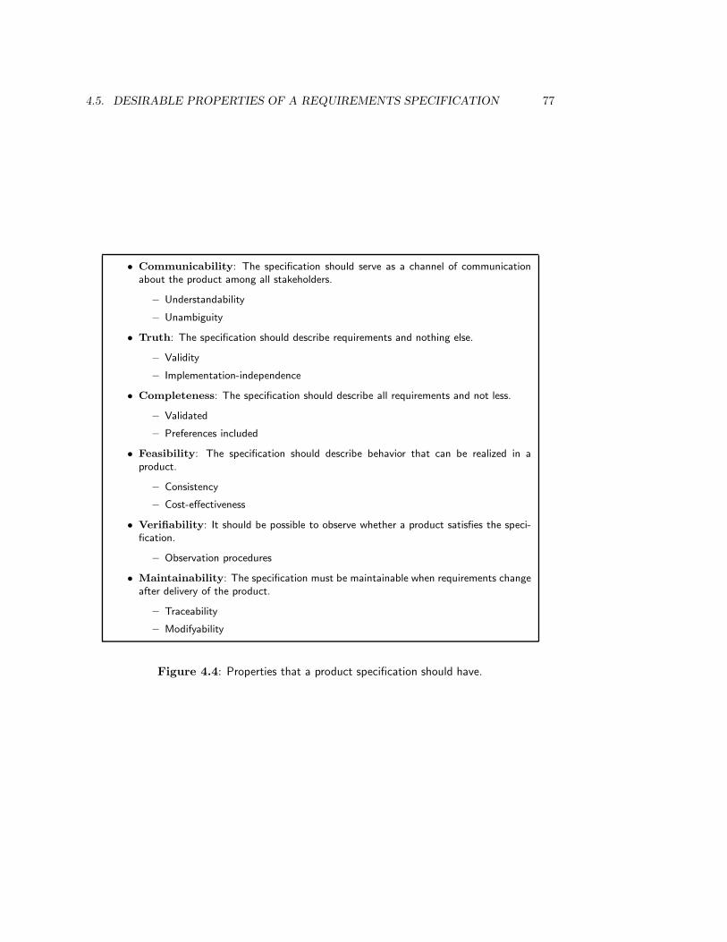
4.5. DESIRABLE PROPERTIES OF A REQUIREMENTS SPECIFICATION 77
• Communicability: The specification should serve as a channel of communicationabout the product among all stakeholders.
– Understandability
– Unambiguity
• Truth: The specification should describe requirements and nothing else.
– Validity
– Implementation-independence
• Completeness: The specification should describe all requirements and not less.
– Validated
– Preferences included
• Feasibility: The specification should describe behavior that can be realized in aproduct.
– Consistency
– Cost-effectiveness
• Verifiability: It should be possible to observe whether a product satisfies the speci-fication.
– Observation procedures
• Maintainability: The specification must be maintainable when requirements changeafter delivery of the product.
– Traceability
– Modifyability
Figure 4.4: Properties that a product specification should have.

78 CHAPTER 4. REQUIREMENTS SPECIFICATIONS
Completeness of a specification entails that no requirement has been omitted from thespecification. In practice, this means that the requirements have been validated with thesponsor and that the sponsor agrees that there are no other requirements to be satisfied.Completeness entails that where possible, constraints have been annotated with preferences.
Feasibility of a specification means, minimally, that the specification is consistent. Bythis we mean that a product that satisfies the specification can exist. A specification thatrequires a response time to be less than 3 seconds and greater than 5 seconds cannot besatisfied and is therefore inconsistent. Beyond this minimal requirement, a specificationshould be cost-effective. This means that the cost of implementing the product is justifiedby the benefit that accrues from implementing it.
A specification is verifiable if there is a cost-effective procedure for ascertaining whethera product satisfies the specification. This means that all properties must be specified in ameasurable way. The observation procedure is the experiment by which the property canbe observed, and it can serve as an acceptance test when the product is handed over to thecustomer.
A specification is maintainable if changes in client or market needs that arise afterdelivery of the product, can be easily incorporated in the specification. If product evolutionis done in a controlled way, changed needs lead to a (re)development process that startswith an update of the product specification. Product evolution by updating the productspecification requires at least modifyability of the specification itself, but in addition, itrequires traceability of the specification in the forward and backwards directions.
4.6 Summary
A requirements specification at any level of the aggregation hierarchy consists of a specifica-tion of product objectives and a specification of observable product behavior. The top levelobjectives of the product link a product specification to the needs of the client or market.At any aggregation level, the behavior specification and decomposition specification of aproduct jointly form the objectives of the lower level product components.
A behavior specification can be as abstract as a product idea, or it can be a more concretespecification of required product functions or even atomic transactions. At each abstractionlevel, properties capture an aspect of product behavior. All properties should be specified ina measurable way, but there may be properties for which only nonbehavioral specificationscan be found. For these properties, proxies should be given that can be behaviorally spec-ified. Properties can be classified under the headings of correctness, reliability, efficiency,security, user-friendliness, maintainability, testability, flexibility, portability, reusability andinteroperability. For positive properties, a finite experiment should be specified in which theproperty can be observed, but for negative properties, which require a certain behavior tobe absent, specifying such a procedure is difficult, if not impossible. Presence of a negativeproperty in a product can only be verified by mathematical or logical proof.
Where possible, preferences should be indicated for different values of a property. Aminimal preference specification is a classification of properties into essential and desirableproperties.
A simple framework for behavior specifications distinguishes a static dimension, in whichstates and static constraints are specified, from a dynamic dimension, in which transitionsand dynamic constraints are specified.

4.7. EXERCISES 79
A product specification must itself satisfy certain requirements. In particular it must betrue, complete, feasible, verifiable and maintainable. Secondary features, which derive fromthese primary ones, include implementation-independence, consistency, cost-effectiveness,modifyability and forward and backward traceability. A very important requirement isthe communicability of the specification, for without this, it could not satisfy any of itsother properties. Two important aspects of communicability are understandability andunambiguity.
4.7 Exercises
1. A certain university faculty sells a lecture notes series to its students. For mostcourses, there is a volume of lecture notes that students can buy. In order to givethese notes a more visible presence on the bookshelves of the students, the facultydecides to design a new style for the cover of the volumes in the series. You are towrite a product specification for the new cover.
(a) Identify the stakeholders of this project.
(b) Write down the list of functions that the product should have.
(c) Write down a list of properties that the functions should have. Use the list offigure 4.2 as a checklist to see if you have forgotten any properties.
(d) List three alternative decomposition specifications that would satisfy the prop-erties and evaluate them with respect to the properties.
2. Consider the TANA case study of chapter 3.
(a) The first iteration through the engineering cycle produced a deliverable contain-ing, as components, a description of the objectives of that iteration, simulationsof the alternatives considered and the evaluation of their effects. Describe thecontents of the objectives and alternatives. How do you think the evaluationswere recorded?
(b) In the second iteration, a deliverable was produced that contains, as components,a description of the generated alternatives and their simulations and evaluations.Describe the contents of these deliverable components.
3. Look up the IEEE/ANSI standard for requirements specifications [156, 90] and classifythe sections in this standard under one of the following headings:
• Top level objectives.
• Product behavior. Classify this as a specification of the product idea, a functionspecification, or a transaction specification.
• Properties, classified according to the list in figure 4.2.
4.8 Bibliographical Remarks
Product objectives and properties. Gladden [116] maintains that the specification ofproduct objectives is a critical success factor in product development. Combined with vivid
80 CHAPTER 4. REQUIREMENTS SPECIFICATIONS
simulation of expected product properties, it will, according to Gladden, lead to a successfulproduct. Although this is probably an overstatement, it is clear that the specification ofproduct objectives plays an important unifying and regulatory role in product development.
Two very useful discussion of the specification of product objectives and properties aregiven by Gause and Weinberg [111] and Gilb [114]. The observation that the difference be-tween objectives and constraints is more in the eye of the beholder than in the requirementsthemselves was made by Simon [317]. The list of kinds of software product properties givenin figure 4.2 is based on a similar list given by Vincent, Waters and Sinclair [350, page 12],who base themselves upon a report by McCall, Richards and Walters [220] and on a discus-sion by Davis [77]. Yeh et al. [374] also give a list of the kinds of “nonfunctional” propertiesthat a software product can have. Keller, Kahn and Panara [172] describe procedures tomake software product properties observable by defining metrics.
Requirements specification. Davis [77] gives a thorough survey of requirements specifi-cation techniques and discusses several standards for requirements specifications. Dorfmanand Thayer [90] contains a large number of requirements specification standards, and Thayerand Dorfman [343] contains a number of useful papers on requirements specification. Sur-veys of the desirable characteristics of requirements specifications are given by Boehm [38],Davis [77] and Lindland et al. [194]. Davis convincingly shows that there are trade-offsamong the desirable properties, such that increased satisfaction of one property impliesdecreased satisfaction of another.
Backward traceability of a specification to reasons is discussed by Potts and Bruns [265].However, Potts and Bruns use a more elaborate argumentation theory than the simplelisting of alternatives, simulations and evaluations proposed here. Backwards traceabilityto sources is proposed by Gotel and Finkelstein [124].

Part II
Requirements EngineeringMethods
81


Chapter 5
ISAC Change Analysis andActivity Study
5.1 Introduction
ISAC (Information Systems Work and Analysis of Changes) was developed in the 1970s atthe Institute for Development of Activities in Organizations in Stockholm, Sweden, underthe direction of Mats Lundeberg. ISAC is a method for client-oriented development ofinformation systems. It is not well-suited to the development of control systems. ISAC wasdeveloped in order to ensure that the business gets the information system it needs. Toreach this goal, ISAC starts with an organizational problem analysis that tries to find realsolutions to real problems. If a solution involves the development of an information system,then ISAC continues developing this system by starting a detailed study of the businessactivities to be supported by the system. To increase the fit between the delivered systemand the business needs, both the problem analysis and the activity study are characterizedby a high degree of participation and cooperation of users, developers and sponsors ofthe information system. The role of developers in these stages is to facilitate the processby which users and sponsors analyze their problems and perform an activity study. Thismeans that developers call meetings, conduct meetings, handle conflicts, identify prejudices,negotiate differences, take care that notes are taken and distributed, present results, etc.
ISAC consists of four stages, which concentrate on user and management questions asshown in figure 5.1. Figure 5.2 shows how ISAC answers these questions. During ChangeAnalysis, current business problems are analyzed, different possible solutions are investi-gated and one solution is chosen. ISAC specifies an activity model for the chosen solution,which is, roughly, a high level specification of the desired business situation in terms ofits activities. Change Analysis is a general problem solving method and is not particu-larly oriented towards defining information system requirements. However, if the solutioninvolves building one or more information systems, then Activity Study determines therequired information system properties. In addition, the important decision whether ornot to automate one or more information systems is made. For each system to be auto-mated, an Information Analysis is performed, which results in a behavior specificationfor each automated system. The term “information analysis” is misleading, for this is used
83
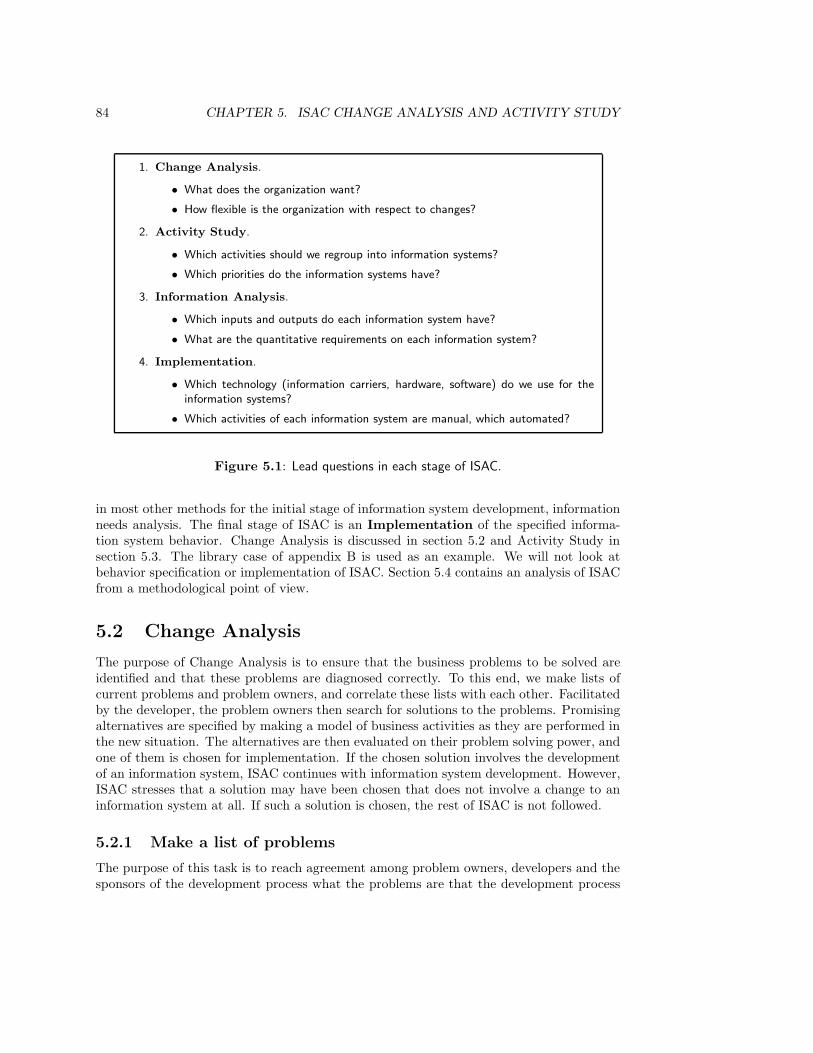
84 CHAPTER 5. ISAC CHANGE ANALYSIS AND ACTIVITY STUDY
1. Change Analysis.
• What does the organization want?
• How flexible is the organization with respect to changes?
2. Activity Study.
• Which activities should we regroup into information systems?
• Which priorities do the information systems have?
3. Information Analysis.
• Which inputs and outputs do each information system have?
• What are the quantitative requirements on each information system?
4. Implementation.
• Which technology (information carriers, hardware, software) do we use for theinformation systems?
• Which activities of each information system are manual, which automated?
Figure 5.1: Lead questions in each stage of ISAC.
in most other methods for the initial stage of information system development, informationneeds analysis. The final stage of ISAC is an Implementation of the specified informa-tion system behavior. Change Analysis is discussed in section 5.2 and Activity Study insection 5.3. The library case of appendix B is used as an example. We will not look atbehavior specification or implementation of ISAC. Section 5.4 contains an analysis of ISACfrom a methodological point of view.
5.2 Change Analysis
The purpose of Change Analysis is to ensure that the business problems to be solved areidentified and that these problems are diagnosed correctly. To this end, we make lists ofcurrent problems and problem owners, and correlate these lists with each other. Facilitatedby the developer, the problem owners then search for solutions to the problems. Promisingalternatives are specified by making a model of business activities as they are performed inthe new situation. The alternatives are then evaluated on their problem solving power, andone of them is chosen for implementation. If the chosen solution involves the developmentof an information system, ISAC continues with information system development. However,ISAC stresses that a solution may have been chosen that does not involve a change to aninformation system at all. If such a solution is chosen, the rest of ISAC is not followed.
5.2.1 Make a list of problems
The purpose of this task is to reach agreement among problem owners, developers and thesponsors of the development process what the problems are that the development process

5.2. CHANGE ANALYSIS 85
1. Change Analysis.
• List problems.
• List problem owners.
• Analyze problems.
• Make current activity model.
• Analyze goals.
• Define change needs.
• Generate change alternatives.
• Make activity model of desired situations.
• Evaluate alternatives.
• Choose activity model.
2. Activity Study.
• Decompose chosen activity model into information subsystems.
— Elaborate chosen activity model.
— Identify information subsystems.
— Analyze suitability for automation.
— Elaborate activity models until each information system is one activity.
• Analyze each information system:
— Analyze contribution of each information system to change objectives.
— Generate ambition levels for information system.
— Test the feasibility of ambition levels.
— Perform cost/benefit analysis of ambition levels.
— Choose ambition level.
• Coordinate information systems.
— Define interfaces between information systems.
— Assign a priority to each information system.
3. Information analysis. For each information system:
• Specify input/output relations for information system.
• Specify data structures for information system.
• Specify process structures for information system.
4. Implementation.
Figure 5.2: The ISAC method.
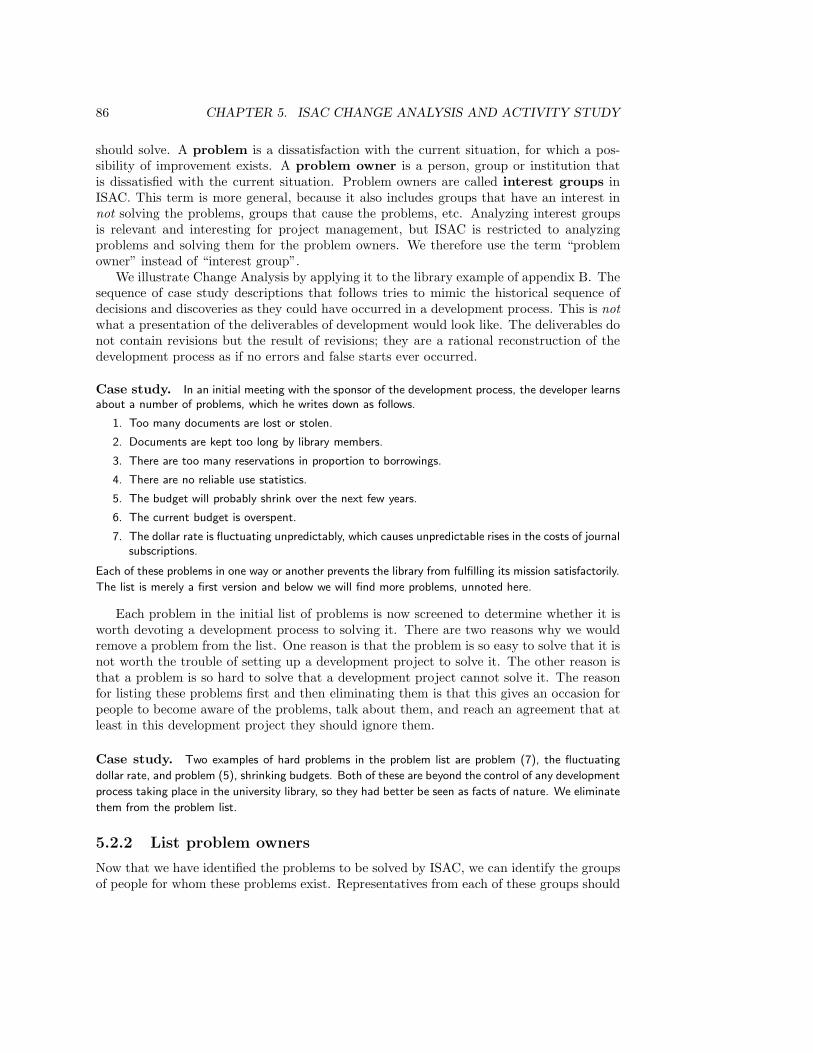
86 CHAPTER 5. ISAC CHANGE ANALYSIS AND ACTIVITY STUDY
should solve. A problem is a dissatisfaction with the current situation, for which a pos-sibility of improvement exists. A problem owner is a person, group or institution thatis dissatisfied with the current situation. Problem owners are called interest groups inISAC. This term is more general, because it also includes groups that have an interest innot solving the problems, groups that cause the problems, etc. Analyzing interest groupsis relevant and interesting for project management, but ISAC is restricted to analyzingproblems and solving them for the problem owners. We therefore use the term “problemowner” instead of “interest group”.
We illustrate Change Analysis by applying it to the library example of appendix B. Thesequence of case study descriptions that follows tries to mimic the historical sequence ofdecisions and discoveries as they could have occurred in a development process. This is notwhat a presentation of the deliverables of development would look like. The deliverables donot contain revisions but the result of revisions; they are a rational reconstruction of thedevelopment process as if no errors and false starts ever occurred.
Case study. In an initial meeting with the sponsor of the development process, the developer learnsabout a number of problems, which he writes down as follows.
1. Too many documents are lost or stolen.
2. Documents are kept too long by library members.
3. There are too many reservations in proportion to borrowings.
4. There are no reliable use statistics.
5. The budget will probably shrink over the next few years.
6. The current budget is overspent.
7. The dollar rate is fluctuating unpredictably, which causes unpredictable rises in the costs of journalsubscriptions.
Each of these problems in one way or another prevents the library from fulfilling its mission satisfactorily.
The list is merely a first version and below we will find more problems, unnoted here.
Each problem in the initial list of problems is now screened to determine whether it isworth devoting a development process to solving it. There are two reasons why we wouldremove a problem from the list. One reason is that the problem is so easy to solve that it isnot worth the trouble of setting up a development project to solve it. The other reason isthat a problem is so hard to solve that a development project cannot solve it. The reasonfor listing these problems first and then eliminating them is that this gives an occasion forpeople to become aware of the problems, talk about them, and reach an agreement that atleast in this development project they should ignore them.
Case study. Two examples of hard problems in the problem list are problem (7), the fluctuating
dollar rate, and problem (5), shrinking budgets. Both of these are beyond the control of any development
process taking place in the university library, so they had better be seen as facts of nature. We eliminate
them from the problem list.
5.2.2 List problem owners
Now that we have identified the problems to be solved by ISAC, we can identify the groupsof people for whom these problems exist. Representatives from each of these groups should
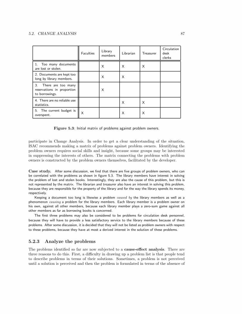
5.2. CHANGE ANALYSIS 87
FacultiesLibrarymembers
Librarian TreasurerCirculationdeskclerks
1. Too many documentsare lost or stolen.
X X X
2. Documents are kept toolong by library members.
X X
3. There are too manyreservations in proportionto borrowings.
X
4. There are no reliable usestatistics.
X X
5. The current budget isoverspent.
X X X
Figure 5.3: Initial matrix of problems against problem owners.
participate in Change Analysis. In order to get a clear understanding of the situation,ISAC recommends making a matrix of problems against problem owners. Identifying theproblem owners requires social skills and insight, because some groups may be interestedin suppressing the interests of others. The matrix connecting the problems with problemowners is constructed by the problem owners themselves, facilitated by the developer.
Case study. After some discussion, we find that there are five groups of problem owners, who canbe correlated with the problems as shown in figure 5.3. The library members have interest in solvingthe problem of lost and stolen books. Interestingly, they are also the cause of this problem, but this isnot represented by the matrix. The librarian and treasurer also have an interest in solving this problem,because they are responsible for the property of the library and for the way the library spends its money,respectively.
Keeping a document too long is likewise a problem caused by the library members as well as aphenomenon causing a problem for the library members. Each library member is a problem owner onhis own, against all other members, because each library member plays a zero-sum game against allother members as far as borrowing books is concerned.
The first three problems may also be considered to be problems for circulation desk personnel,
because they will have to provide a less satisfactory service to the library members because of these
problems. After some discussion, it is decided that they will not be listed as problem owners with respect
to these problems, because they have at most a derived interest in the solution of these problems.
5.2.3 Analyze the problems
The problems identified so far are now subjected to a cause-effect analysis. There arethree reasons to do this. First, a difficulty in drawing up a problem list is that people tendto describe problems in terms of their solutions. Sometimes, a problem is not perceiveduntil a solution is perceived and then the problem is formulated in terms of the absence of

88 CHAPTER 5. ISAC CHANGE ANALYSIS AND ACTIVITY STUDY
the perceived solution, such as “there is no magnetic labeling of documents.” The purposeof problem analysis is to eliminate solution-oriented problems as much as possible and getto the underlying problems. This makes room for alternative solutions. Second, problemanalysis is another way to reduce the problem list in size, in addition to the elimination ofeasy and hard problems. Problem analysis allows us to limit ourselves to the underlyingproblems only. Third, problem analysis helps us preparing an effective action, becausethe rest of the Change Analysis can then concentrate on the underlying causes and ignorederived problems.
Cause-effect analysis is performed by domain specialists, people who have expertknowledge of the problems under study. A domain specialist may be a problem owner, anend user of the required system, a sponsor, an outside specialist, a manager, etc. The resultof analysis is represented in a cause-effect graph, which is a directed graph in which nodesrepresent problems and arrows point from cause to effect.
Case study. Figure 5.4 contains a cause-effect graph for the library case. During analysis, a numberof underlying problems are discovered. One cause of overspending the budget is that documents aremultiply acquired by different departments and that different departments have subscriptions to thesame journals. This is called the problem of multiple acquisitions. It can be in turn traced to the factthat acquisitions of different departments are not coordinated. The problems of multiple acquisitionsand lack of coordination are added to the problem list.
The problem of the high reservation/borrowing ratio is caused by the bad availability of books,which is in turn caused by the two problems of losing/stealing books and of not returning books. Oneof the causes of lost/stolen books is improper supervision on the return of documents, which makesit possible for library members to steal a book that someone else returned but is not yet registered astaken in by the library. Another cause of lost/stolen documents is that all books and journals are storedin rooms open to the library members, so that they can browse through them but can also easily stealthem. This problem is added to the problem list.
The librarian insists that an important cause of lost/stolen documents as well as for the fact thatdocuments are kept too long is bad member mentality. It is quite possible to see this as a fact ofnature, like the problems of shrinking budgets and fluctuating dollar rates, but the librarian believesthat an education campaign can change this mentality, so the developer adds it to the problem list andcause-effect graph.
Finally, it is discovered during analysis that one cause of the overlong borrowing periods is that
library personnel has no time to go through the list of borrowed books each week to find out which
books have been borrowed longer than their allotted borrowing period. Manual procedures also increase
the cost of levying fines. The cause-effect graph and problem list are updated accordingly. The matrix
of problems against problem owners is updated into the one shown in figure 5.5.
In addition to doing a cause-effect analysis, a quantitative study should be madeof the problems. The reason for this is simple: in order to decide upon investing in asolution process, the severity of the problems must be assessed first. For example, howmany documents are stolen each year? For how long do borrowers exceed allowed borrowingperiods? What is the ratio between reservations and borrowings?
Quantifying the problems has three advantages. First, only a quantitative characteri-zation of these problems can give an indication of the potential benefit to be derived fromsolving the problems. Second, only if a problems is quantified is it possible to know in thefuture whether and to what extent it is solved. Third, if quantification shows that a prob-lem has only a slight impact on the business, the sponsor may make only a small budget
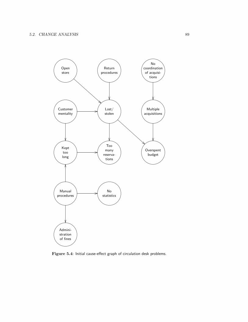
5.2. CHANGE ANALYSIS 89
Openstore
Returnprocedures
Nocoordinationof acquisi-
tions
Customermentality
Lost/stolen
Multipleacquisitions
Kepttoolong
Overspentbudget
Toomany
reserva-tions
Manualprocedures
Admini-strationof fines
Nostatistics
Figure 5.4: Initial cause-effect graph of circulation desk problems.
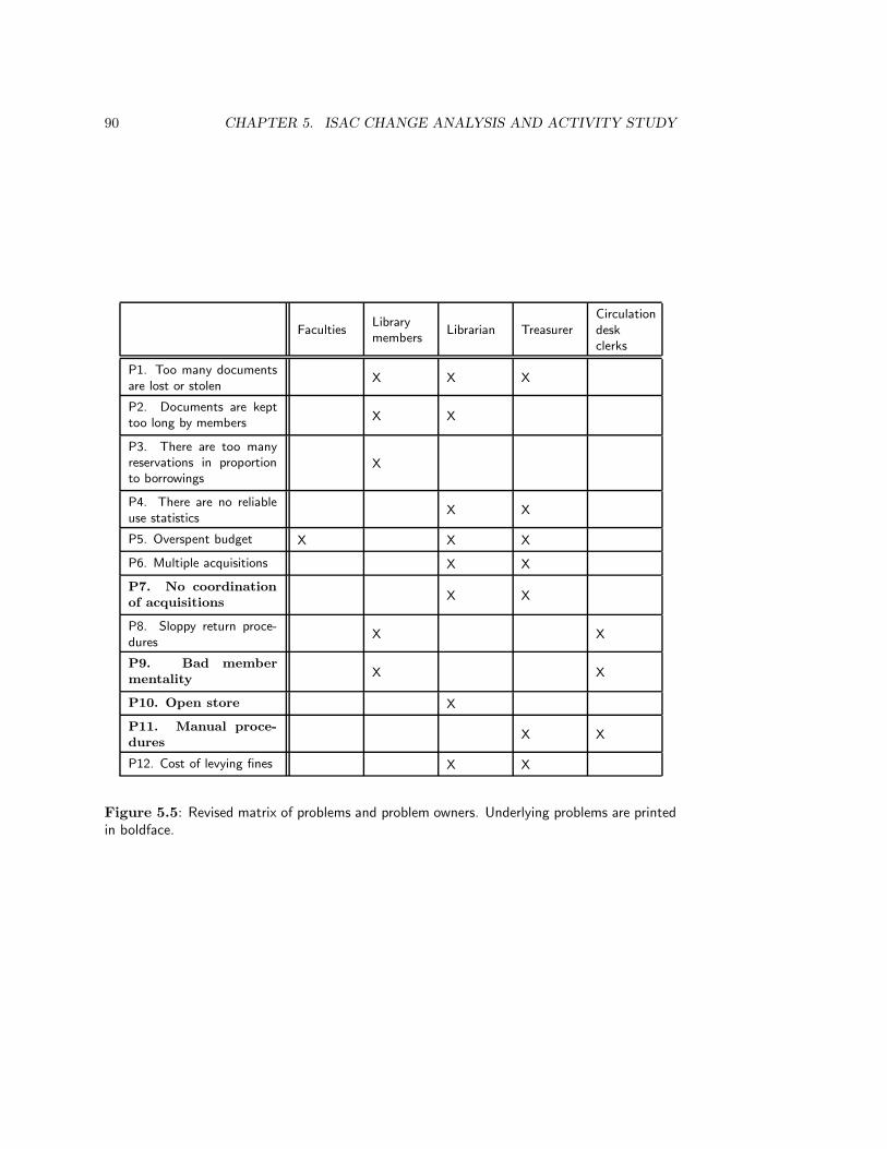
90 CHAPTER 5. ISAC CHANGE ANALYSIS AND ACTIVITY STUDY
FacultiesLibrarymembers
Librarian TreasurerCirculationdeskclerks
P1. Too many documentsare lost or stolen
X X X
P2. Documents are kepttoo long by members
X X
P3. There are too manyreservations in proportionto borrowings
X
P4. There are no reliableuse statistics
X X
P5. Overspent budget X X X
P6. Multiple acquisitions X X
P7. No coordinationof acquisitions
X X
P8. Sloppy return proce-dures
X X
P9. Bad membermentality
X X
P10. Open store X
P11. Manual proce-dures
X X
P12. Cost of levying fines X X
Figure 5.5: Revised matrix of problems and problem owners. Underlying problems are printedin boldface.
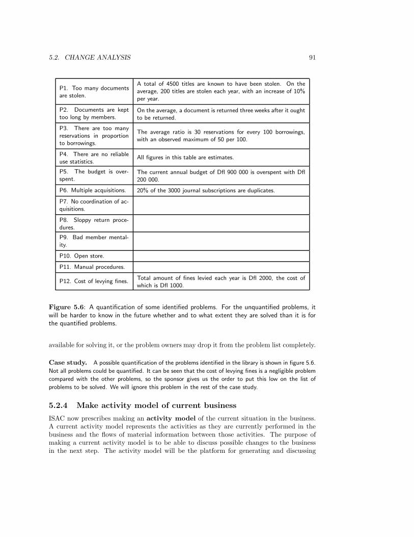
5.2. CHANGE ANALYSIS 91
P1. Too many documentsare stolen.
A total of 4500 titles are known to have been stolen. On theaverage, 200 titles are stolen each year, with an increase of 10%per year.
P2. Documents are kepttoo long by members.
On the average, a document is returned three weeks after it oughtto be returned.
P3. There are too manyreservations in proportionto borrowings.
The average ratio is 30 reservations for every 100 borrowings,with an observed maximum of 50 per 100.
P4. There are no reliableuse statistics.
All figures in this table are estimates.
P5. The budget is over-spent.
The current annual budget of Dfl 900 000 is overspent with Dfl200 000.
P6. Multiple acquisitions. 20% of the 3000 journal subscriptions are duplicates.
P7. No coordination of ac-quisitions.
P8. Sloppy return proce-dures.
P9. Bad member mental-ity.
P10. Open store.
P11. Manual procedures.
P12. Cost of levying fines.Total amount of fines levied each year is Dfl 2000, the cost ofwhich is Dfl 1000.
Figure 5.6: A quantification of some identified problems. For the unquantified problems, itwill be harder to know in the future whether and to what extent they are solved than it is forthe quantified problems.
available for solving it, or the problem owners may drop it from the problem list completely.
Case study. A possible quantification of the problems identified in the library is shown in figure 5.6.
Not all problems could be quantified. It can be seen that the cost of levying fines is a negligible problem
compared with the other problems, so the sponsor gives us the order to put this low on the list of
problems to be solved. We will ignore this problem in the rest of the case study.
5.2.4 Make activity model of current business
ISAC now prescribes making an activity model of the current situation in the business.A current activity model represents the activities as they are currently performed in thebusiness and the flows of material information between those activities. The purpose ofmaking a current activity model is to be able to discuss possible changes to the businessin the next step. The activity model will be the platform for generating and discussing
92 CHAPTER 5. ISAC CHANGE ANALYSIS AND ACTIVITY STUDY
alternative solutions. Activity models are made only after the problem analysis, for this willhelp the analyst to draw boundaries around the systems under development. In particular,it will help the analyst to distinguish relevant from irrelevant systems when activity modelsare made.
The ISAC technique for representing activity models is the A-schema. We will not usethis, because ISAC tends to be identified with the use of these schemas, and using themwould lead attention away from the real core of ISAC, the identification of problems andproblem owners and the modeling of business activities. Instead, we use a simple diagramnotation already used in chapter 2. Figure 5.7 gives an example. The following conventionsare used.
• Subsystems are either activities or stores. Stores are passive entities in which anunlimited supply of data items or material items can be kept. Activities and storesmay be decomposed into subsystems. An activity can have activities and stores assubsystems, but stores can only have stores as subsystems. The decomposition of asubsystem is shown in a separate diagram, so that each diagram contains a nestingonly one level deep. For example, figure 5.7 shows three of the activities of the libraryas subsystems. A decomposition of the circulation activity is shown in figure 5.8. Thename of an activity or store should make clear whether the subsystem is an activityor store.
• Transactions between subsystems are represented by arrows, whose direction indicatesthe direction of the flow of data or material items in the transaction. Interactions maybe bidirectional. The names of the flows indicate the kind of data or material itempassing through the flow. To distinguish transactions from accidental line intersec-tions, a black dot is drawn on the intersection that represents the interaction. Theborrow request flow in figure 5.8 is an example of this. To keep the top-level diagramsimple, only the major flows are shown in this diagram.
For the moment, this suffices to determine the meaning of the diagrams. As an aside,we remark that the subsystem diagrams used here could equally well be replaced by thedata flow diagrams of chapter 9, by the activity charts of Statemate [153, 139], or by othersuitable notation systems. In this chapter, we will call the subsystem diagrams drawnaccording to the above conventions activity diagrams.
Case study. Figure 5.7 shows an activity model of the library. The diagram shows three groupsof activities performed in the library. There are no stores in this diagram. The two external systems,PUBLISHER and MEMBER, represent systems that generate input for the library or that receiveoutput from the library. Because PUBLISHER and MEMBER are types that can have many instances,arbitrary instances P and M of these types are declared. The library interacts with many publishers andmany members, but only one typical member of each class of systems is shown. The model as showndoes not show all details, but it does give an impression of the major activities performed in the library,and their interfaces.
Looking at our problem list (figure 5.6), we see that we have problems in the acquisition andcirculation activities. The problem in the acquisition activity is that duplicate acquisitions are performed.To solve this problem, we should zoom in on this activity and see how it is actually performed. Theresulting model of the acquisition activity can then serve as a basis for discussing possible alternativeways of performing the activity.
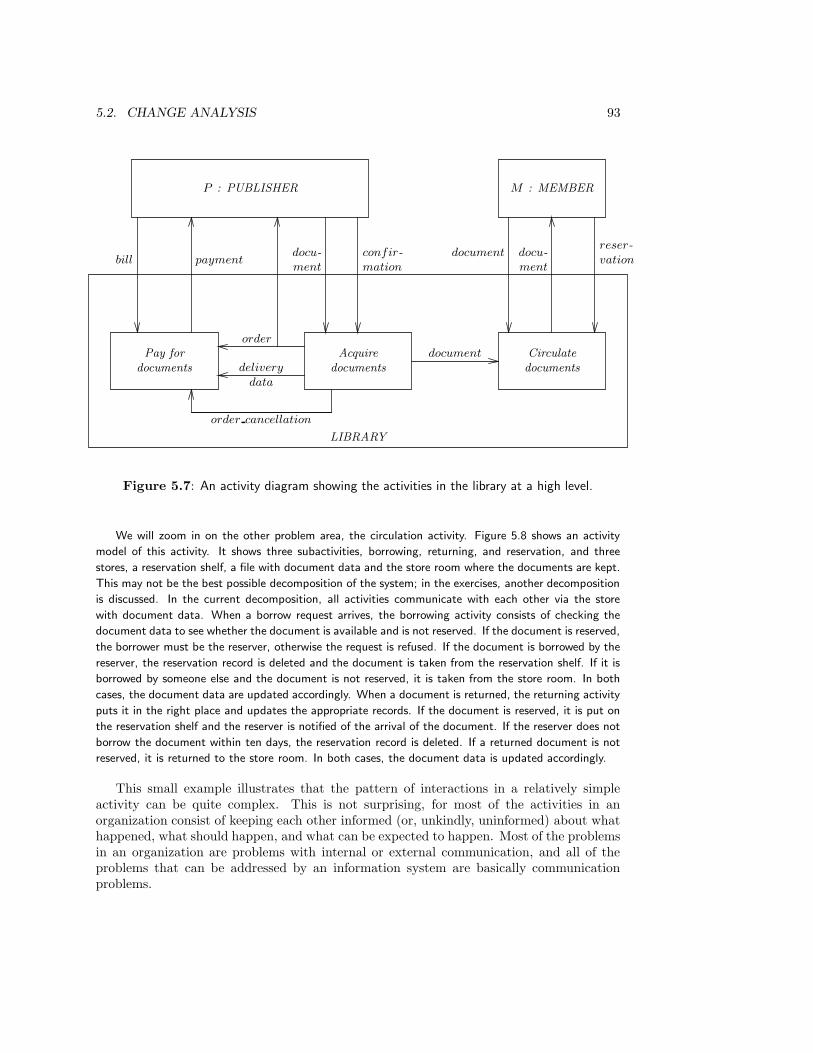
5.2. CHANGE ANALYSIS 93
LIBRARY
P : PUBLISHER M : MEMBER
Circulate
documents
Pay for
documents
Acquire
documents
document docu-
ment
reser-
vationbill paymentdocu-
ment
confir-
mation
order
delivery
data
order cancellation
document
Figure 5.7: An activity diagram showing the activities in the library at a high level.
We will zoom in on the other problem area, the circulation activity. Figure 5.8 shows an activity
model of this activity. It shows three subactivities, borrowing, returning, and reservation, and three
stores, a reservation shelf, a file with document data and the store room where the documents are kept.
This may not be the best possible decomposition of the system; in the exercises, another decomposition
is discussed. In the current decomposition, all activities communicate with each other via the store
with document data. When a borrow request arrives, the borrowing activity consists of checking the
document data to see whether the document is available and is not reserved. If the document is reserved,
the borrower must be the reserver, otherwise the request is refused. If the document is borrowed by the
reserver, the reservation record is deleted and the document is taken from the reservation shelf. If it is
borrowed by someone else and the document is not reserved, it is taken from the store room. In both
cases, the document data are updated accordingly. When a document is returned, the returning activity
puts it in the right place and updates the appropriate records. If the document is reserved, it is put on
the reservation shelf and the reserver is notified of the arrival of the document. If the reserver does not
borrow the document within ten days, the reservation record is deleted. If a returned document is not
reserved, it is returned to the store room. In both cases, the document data is updated accordingly.
This small example illustrates that the pattern of interactions in a relatively simpleactivity can be quite complex. This is not surprising, for most of the activities in anorganization consist of keeping each other informed (or, unkindly, uninformed) about whathappened, what should happen, and what can be expected to happen. Most of the problemsin an organization are problems with internal or external communication, and all of theproblems that can be addressed by an information system are basically communicationproblems.
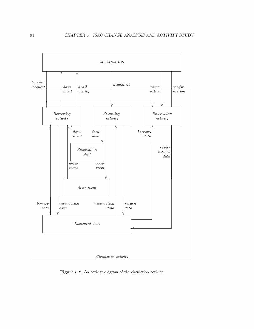
94 CHAPTER 5. ISAC CHANGE ANALYSIS AND ACTIVITY STUDY
Circulation activity
M : MEMBER
Returning
activity
Borrowing
activity
Reservation
activity
Reservation
shelf
Store room
docu-
ment
docu-
ment
Document data
borrow
request
•
docu-
ment
avail-
ability
documentreser-
vation
confir-
mation
borrow
data
reservation
data
return
data
reservation
data
docu-
ment
docu-
ment
borrow
data
reser-
vation
data
Figure 5.8: An activity diagram of the circulation activity.

5.2. CHANGE ANALYSIS 95
5.2.5 Analyze goals
We now understand the problems, know who the problem owners are, and have a model ofcurrent business activities. Before we investigate possible changes to the current situation,we should list the goals of the development process. A goal is simply a desired situation.We must specify goals at this stage in order to know how to evaluate solution proposals.The specification of goals allows us to understand why the problems identified earlier areproblems at all, and what sponsors and problem owners want to achieve by the developmentprocess.
A goal specification should be declarative; it specifies the desired result, not a way toreach this result. For example, instead of specifying the goal that an information systemshould provide payment information within one day, we should specify the goal that thisinformation should be available within one day. This opens up the possibility that thisinformation could be made available by other means than the company information system.
Even if all goal specifications are declarative, we can order goals in a tree such thatthe descendants of each node represent subgoals of the node. The root of this tree is thebusiness mission. Since any goal in this tree is a means to a higher goal, the injunctionto specify goals, not means, is strictly speaking vacuous. This is fully analogous to theconfusion about what are requirements and implementations. Only the root of the tree isnot a means to a higher goal (in the tree). However, only a subset of nodes in the treerepresent goals that allow us to evaluate change proposals. These goals can be found byinterviewing problem owners and asking them which situation they would like to achieve.We should specify goals that lie in this subset but are otherwise as high up in the tree aspossible, but not higher.
Drawing up a list of goals may require a lot of negotiation, because different problemowners may have contradictory goals. To resolve contradictory goals, one moves to a higherlevel goal in the tree upon which all problem owners can agree. Ultimately, the mission ofthe business is reached, and it is to be hoped that there is at least agreement about that.
Case study. A discussion with the different problem owners reveals the following list of goals:
• Library members and faculties:
– All books and journals in the relevant research area should be borrowable.
– Documents should be optimally available.
– The library should have several copies of books used for courses given by the faculty, to beused by students.
– Students should be able to use educational material in study rooms of the library.
• Librarian and treasurer.
– Documents should be optimally available.
– The expenses of the library should remain within budget.
– Accurate and up-to-date statistics on library use should be available.
• Circulation desk.
– The number of reservations done because some member does not return a borrowed docu-ment in time should be minimized.
96 CHAPTER 5. ISAC CHANGE ANALYSIS AND ACTIVITY STUDY
– The work done in connection with members who are too late with returning the documentsshould be minimized.
– The work done in connection with lost documents should be minimized.
We try to harmonize this list by moving to higher level goals about which agreement can be reached.After negotiation, we get the following goals. The first goal is worked out by already specifying twomeans by which this goal can be reached.
G1 Documents should be maximally available.
G1.1 Books should be returned in time.
G1.2 The number of losses should be minimized.
G2 Keep library expenses within budget.
G3 Optimize the service of the circulation desk.
G4 Keep statistics accurate and up-to-date.
These goals are general enough to be related to the mission of the library, yet specific enough to be
related to the goals of the different problem owners. It is instructive to trace these goals to the initial
list of goals above, and check which of those initial goals have not made it to the final list. The relation
between this final goal list and our initial goal list is that if we ask “Why?” of any of the goals in the
initial list that does not appear in the final list, we should be able to answer with one of the goals in
the final list. The final goal list is related in the same way to the library mission: The mission answers
the “Why?” question for any of our final goals.
5.2.6 Define change needs
One of the functions of a list of goals is to be able to give the reason why the problemsare problems at all. Conversely, for each goal we can identify the reasons why it is notachieved by listing the problems that impede achievement of the goal. If we do this, wefind that we can cluster problems into groups of similar problems that are related to thesame or similar goals. One way to do this is to make a matrix of problems against goalsand try to find clusters of related problems. There is no algorithm to do the clustering; theunderstanding of the situation gained by analyzing it from different angles should sufficeto make the clusters. Each cluster defines a change need that will act as a goal of thedevelopment process.
Case study. Comparing the problem list with the goal list, we get the following clusters, each ofwhich is a change need. For each change need, we list the problems it is intended to solve and the goalsthat the change should help to achieve.
• Return procedures should be improved so that document availability and the service to thecustomer are maximized.Problems: P2, P3, P8, P11.Goals: G1, G3.
• Acquisitions should be coordinated so that multiple acquisitions are reduced.Problems: P5, P6, P7.Goals: G2.
• Statistics should be improved.
Problem: P4.Goal: G4.

5.2. CHANGE ANALYSIS 97
• The possibility of theft should be reduced.
Problem: P10.Goal: G1.
In accordance with the directives of the sponsor, solving problem P12 is not part of our change needs.
5.2.7 Generate change alternatives
We are now armed with sufficient ammunition to generate change alternatives. This is bestdone in a brainstorming session, in which any idea at all is written down without evaluationor critique. Initially, the alternatives are only sketched in the barest outline. Elaborationand evaluation will be done in the next steps.
Case study. Here are some alternatives for the library case:
A1 Reduce theft by removing all documents from the reach of members.
A2 Reduce theft by marking all books with an indelible and invisible magnetic marker and place portswith sensors at library entries.
A3 Improve supervision on document return procedures by reducing the number of entries/exits tothe library department to one, and by organizing a strict schedule under which there will alwaysbe one library functionary at the entry/exit desk.
A4 Facilitate the production of use statistics by implementing an automated information system.
A5 Facilitate automatic reporting on members who extend their borrowing period beyond allowablelimits by implementing an automated information system.
The alternatives are not all mutually exclusive, but some, such as the first two, are. Some of them
involve changes to the information system of the library, including automation; others take measures
not involving automation or even the information system.
5.2.8 Make activity model of desired situations
We now make packages of one or more change alternatives that are worth investigating. Toinvestigate a package, we make an activity model of it. This makes the package a possibletopic of rational discussion and allows us to compare it with the current situation.
Case study. Here are a number of packages that can be constructed from the available alternatives.
1. Change nothing at all (the null package). This package should always be included, simply becausewe want to compare the possible changes with the current situation.
2. A1: Put all documents in a separate store room.
3. A2 & A3: Use magnetic markers and reduce the number of entries.
4. A4 & A5: Implement an automated information system.
Elaborating the automation package, we find that we have to add at least two activities to the com-munication diagram of figure 5.8: producing a list of overdue documents and their borrowers, andsending reminders to members. Both activities should be performed daily. This has become feasible byautomation. Activities for other functions, related to the production of statistics, could be added aswell. The extended communication diagram is not shown here.
The package in which a separate store room is introduced for documents, inaccessible for librarymembers, introduces a new system, the Store Room, with a number of interactions when documents
98 CHAPTER 5. ISAC CHANGE ANALYSIS AND ACTIVITY STUDY
are put into the Store or fetched from it. Making a model of this situation is left as an exercise for thereader.
If you try to model the magnetic marker package (A2+A3), you find that it has exactly the same
communication diagram as the current situation. This is because only the implementation technology
changes, not the pattern of communications. Communication diagrams will not represent every change
made to the situation. (The same holds for the A-schemas used in ISAC.)
5.2.9 Evaluate alternatives
For each of the packages that are modeled, we now estimate what their problem solvingpower is. Very few solutions are such that they do not introduce problems; in fact, everysolution is the seed of a new batch of problems. We therefore also investigate which problemsare introduced by each package, and for whom. This is done by making, for each package, amatrix of problems against problem owners, and indicating in this matrix which problemsare solved and which are introduced.
Case study. Figure 5.9 contains the matrix for the automation package (A4 & A5) together withA1 or with A2 & A3 (it is immaterial for the matrix which is chosen). An “O” in an entry means thatthe problem is solved for the problem owner.
Two extra problems are introduced, P13 and P14. Problem P13 is that the library members
would experience this new situation as a rigid borrowing discipline. There is no guarantee that this
would change member mentality, so this problem is not indicated as being reduced by this alternative.
Problem P14 is introduced by solving problems P6 and P7. The faculties and library members have a
problem with not being allowed multiple acquisitions, for now they have to go by foot, bicycle or car to
another department to find the books or journals they want! Evaluation of this situation may lead to
extra measures, such as a facility for internal document transfers.
Solving problems is a good thing and introducing problems is a bad thing. The question is,how good and how bad is it? We must evaluate the expected impact of a package againstthe goals of development, identified earlier. Different alternatives should not be comparedwith each other, because this could lead to a war over pet proposals.
Case study. The automation package (A4 & A5) together with the magnetic marker and single
entry options (A2 & A3) score best with respect to the development goals. In particular, they do not
introduce the problem introduced by A1, that users of the library cannot browse through the books
anymore.
5.2.10 Choose an alternative
The sponsor is presented with a report about the evaluation of alternatives and then choosesone of them. The developer may suggest a choice, but it is important that the sponsorauthorizes this choice because it significantly affects the use of resources in the rest of thedevelopment process.
Case study. Altogether, it is decided that the following changes will be implemented in the library:
• Terminate double journal subscriptions.
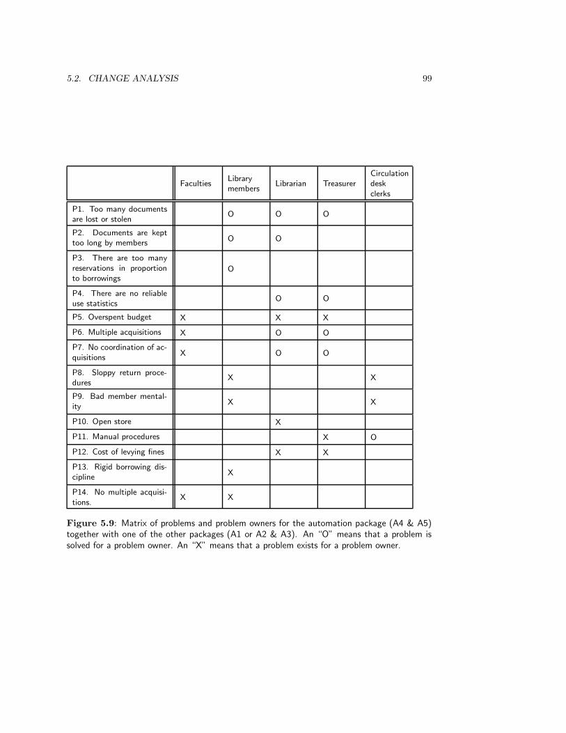
5.2. CHANGE ANALYSIS 99
FacultiesLibrarymembers
Librarian TreasurerCirculationdeskclerks
P1. Too many documentsare lost or stolen
O O O
P2. Documents are kepttoo long by members
O O
P3. There are too manyreservations in proportionto borrowings
O
P4. There are no reliableuse statistics
O O
P5. Overspent budget X X X
P6. Multiple acquisitions X O O
P7. No coordination of ac-quisitions
X O O
P8. Sloppy return proce-dures
X X
P9. Bad member mental-ity
X X
P10. Open store X
P11. Manual procedures X O
P12. Cost of levying fines X X
P13. Rigid borrowing dis-cipline
X
P14. No multiple acquisi-tions.
X X
Figure 5.9: Matrix of problems and problem owners for the automation package (A4 & A5)together with one of the other packages (A1 or A2 & A3). An “O” means that a problem issolved for a problem owner. An “X” means that a problem exists for a problem owner.
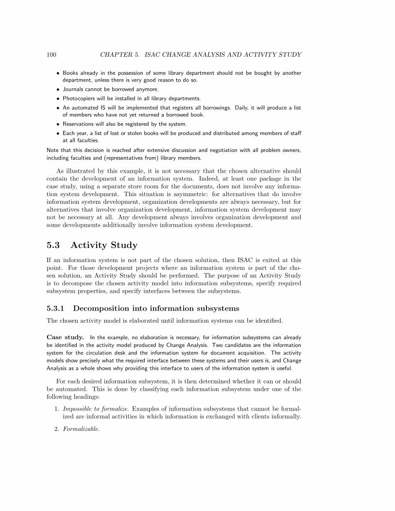
100 CHAPTER 5. ISAC CHANGE ANALYSIS AND ACTIVITY STUDY
• Books already in the possession of some library department should not be bought by anotherdepartment, unless there is very good reason to do so.
• Journals cannot be borrowed anymore.
• Photocopiers will be installed in all library departments.
• An automated IS will be implemented that registers all borrowings. Daily, it will produce a listof members who have not yet returned a borrowed book.
• Reservations will also be registered by the system.
• Each year, a list of lost or stolen books will be produced and distributed among members of staffat all faculties.
Note that this decision is reached after extensive discussion and negotiation with all problem owners,
including faculties and (representatives from) library members.
As illustrated by this example, it is not necessary that the chosen alternative shouldcontain the development of an information system. Indeed, at least one package in thecase study, using a separate store room for the documents, does not involve any informa-tion system development. This situation is asymmetric: for alternatives that do involveinformation system development, organization developments are always necessary, but foralternatives that involve organization development, information system development maynot be necessary at all. Any development always involves organization development andsome developments additionally involve information system development.
5.3 Activity Study
If an information system is not part of the chosen solution, then ISAC is exited at thispoint. For those development projects where an information system is part of the cho-sen solution, an Activity Study should be performed. The purpose of an Activity Studyis to decompose the chosen activity model into information subsystems, specify requiredsubsystem properties, and specify interfaces between the subsystems.
5.3.1 Decomposition into information subsystems
The chosen activity model is elaborated until information systems can be identified.
Case study. In the example, no elaboration is necessary, for information subsystems can already
be identified in the activity model produced by Change Analysis. Two candidates are the information
system for the circulation desk and the information system for document acquisition. The activity
models show precisely what the required interface between these systems and their users is, and Change
Analysis as a whole shows why providing this interface to users of the information system is useful.
For each desired information subsystem, it is then determined whether it can or shouldbe automated. This is done by classifying each information subsystem under one of thefollowing headings:
1. Impossible to formalize. Examples of information subsystems that cannot be formal-ized are informal activities in which information is exchanged with clients informally.
2. Formalizable.

5.3. ACTIVITY STUDY 101
Attribute Measure Current High ambition Low ambition
Response timeSeconds in realtime
Not applicable2 sec. avg. perday5 sec. max.
5 sec. avg. perday20 sec. max.
Volume of trans-actions
Totalnumber per dayfor library
30 avg. per day60 max.
200 avg. per day300 max.
50 avg. per day100 max.
Latency of data
Real time be-tween event oc-currence and da-tabase transac-tion
1 day avg. peryear1 day max.
1 second avg.per day1 hour max.
1 sec. avg. perday1 day max.
Figure 5.10: Table of ambition levels for some system attributes.
(a) Not suitable for automation. Photos made by X-ray scanners can be printedand stored in manual archives or they can be digitized and stored in computermemory. Due to privacy reasons, however, it may be decided that this activityis not suitable for automization.
(b) Suitable for automation. The library administration is an example of this.
Case study. The Circulation and Acquisition information systems are both going to be automated.
Note that we already chose an automation alternative in Change Analysis, so this analysis seems su-
perfluous. One can also turn this around and say that this part of activity analysis has already been
performed simultaneously with Change Analysis.
Having identified the information subsystems that will be automated, the activity modelof the desired situation is elaborated to the point where each future information system isrepresented by one activity in the model. The resulting model then represents the orga-nizational context of all desired information systems, and represents the interfaces of eachsystem to its organizational context.
5.3.2 Analysis of information subsystems
For each system to be automated, desired properties are specified, called ambition levels.Examples of ambition levels are limits on response time, timeliness of output, volume andfrequency of input, and requirements on the quality of input and output data. These areoften specified nonbehaviorally, or behavioral specifications of proxies are given.
Case study. ISAC uses a cumbersome specification of desirable system attributes and ambition
levels, which is too elaborate to use for illustration here. A simplified presentation of a list of ambition
levels is given in figure 5.10.
Each ambition level is then tested for its feasibility. ISAC recommends the followingways for feasibility testing:

102 CHAPTER 5. ISAC CHANGE ANALYSIS AND ACTIVITY STUDY
Social systemChange Analysis: Analyze business problems and indicatea solution direction.
Computer-based systemsActivity Study: Work out the solution and identifycomputer-based information systems in it; specify requiredproperties of these systems.
Software systemsInformation analysis: Specify external behavior of auto-mated information system(s).
Software subsystemsImplementation: Construct automated information sys-tem(s).
Figure 5.11: ISAC’s coverage of aggregation levels.
• Find out if projects with similar objectives have realized information systems withsimilar ambition levels.
• Simulate the ambition levels by means of computational models.
• Build a prototype that satisfies a number of the properties of an ambition level anddo a field test with it, i.e. let users actually work with it.
In addition to these tests a cost/benefit analysis of each ambition level is performed. Onthe basis of these tests and analyses, the ambition levels are evaluated and a choice is madefor one ambition level.
5.3.3 Coordination of information subsystems
Activity Study ends with a precise definition of the interfaces of the information systems,and the assignment of priorities to them. It can be argued that the precise specification ofinterfaces is already part of the next task, called information analysis in ISAC, and which isconcerned with giving a precise external behavior specification of each information system.The specification of priorities of information systems is an important task in planning thespecification and implementation of the information systems.
5.4 Methodological Analysis
5.4.1 The place of ISAC in the development framework
ISAC can be mapped to the aggregation hierarchy of systems as shown in figure 5.11. Thefigure also contains the motivation for allocating the stages of ISAC to these levels.
Figure 5.12 shows that Change Analysis follows the requirements engineering cycle stepby step. It also shows that half of the energy in Change Analysis is devoted to trying tounderstand the problem. This agrees with the advice of experienced consultants: don’t rushto solutions.
Having indicated a business solution in the form of a high-level activity model of thedesired situation, ISAC continues, in the Activity Study, to elaborate this into a more

5.4. METHODOLOGICAL ANALYSIS 103
Requirements engineering cycle Change Analysis
Analyze needs
• List problems
• List problem owners
• Analyze problems (matrix, causes)
• Make current activity model
• Analyze goals
• Define change needs
Synthesize alternative solutions • Generate change alternatives
Simulate solutions
• Make activity model of each change proposal
• Make problem/problem owner matrix of each changeproposal
Evaluate solutions • Evaluate against change goals
Choose a solution • Choose
Figure 5.12: Change Analysis as an iteration through the requirements engineering cycle atthe business level.
detailed model of activities and to identify those activities that (1) are information systemsthat (2) must be automated. For each information system to be automated, requiredproperties are specified. Figure 5.13 shows that the specification of the required propertiesfollows the requirements engineering cycle with almost as exact a match as Change Analysishas with the requirements engineering cycle.
After the required system properties have been specified, the behavior of each subsystemis specified in information analysis. Since, according to figure 5.11, information analysis isone level lower in the aggregation hierarchy, one may wonder where the decomposition takesplace that is needed to move to the next lower level. This decomposition takes place byfocusing, in information analysis, on the external behavior of software systems. A computer-based information system has two kinds of subsystems, software systems and people, alsocalled (end-)users of the information system. The specification of procedures to be followedby the users is not listed explicitly as a separate task in ISAC. In practice, this meansthat the specification of user procedures is taken to be a derivative task of the specificationof external software behavior. There is something to say for turning this around, andcontinuing after Activity Study with the specification of user procedures. After the usermanuals have been written, one can then turn to the specification and implementationof software to support these procedures. Howes [147, 148] discusses the advantages andlimitations of this way of working.
104 CHAPTER 5. ISAC CHANGE ANALYSIS AND ACTIVITY STUDY
Logical development task Activity study
Decompose system
• Decompose chosen activity model into informationsubsystems.
— Elaborate chosen activity model.
— Identify information subsystems.
— Analyze suitability for automation.
— Elaborate activity models until each informationsystem is one activity.
Specify subsystemrequirements
Analyze
• Analyze information subsystems.
— Analyze contribution of each information subsys-tem to change objectives.
Synthesize— Generate ambition levels for each information sub-
system.
SimulateEvaluate
— Test the feasibility of ambition levels.
— Perform cost/benefit analysis of ambition levels.
Choose — Choose ambition level.
• Coordinate information subsystems
— Determine interfaces between information subsys-tems.
— Assign priority to information subsystems.
Figure 5.13: Activity Study as organization decomposition and information subsystem speci-fication.

5.4. METHODOLOGICAL ANALYSIS 105
5.4.2 Activity modeling
Notations. The diagram technique used in this chapter to represent activity models hasa close resemblance to known techniques such as A-schemas in ISAC, data flow diagramsin structured analysis (chapter 9) and activity charts in STATEMATE [153, 139]. It shareswith these other graphical notations the separation of subsystems into passive and activeones. However, in these other notations, stores cannot be decomposed into substores. I donot see why this should be prohibited. Databases can be decomposed into tables, and thesecan be further partitioned into fragments as needed. Anything goes, as long as it allows usto specify the required business activities with the required clarity.
Activities and stores. The decomposition of activities into subactivities and passivestores is a principle that pervades structured behavior modeling. It is responsible for theunnecessarily complex communication pattern in figure 5.8. Some flows in the activitydiagram represent access of an activity to a store to retrieve data that it has itself putthere. If we had encapsulated the stores in the activities to begin with, then we wouldhave a diagram that shows less interaction and should therefore be easier to understand.Exercise 2 gives an example of this.
Primary and secondary flows. A-schemas use a convention to distinguish the flow ofmaterial from the flow of data. Material flows are represented by bold lines, data flowsby thin lines. The intention behind this notation is to distinguish the primary flow ofgoods from the secondary flow of data. However, the distinction between material and dataflows does not coincide with the distinction between the primary process and secondary,supporting business processes. For example, the primary process of organizations like banksand insurance companies consists of data flows. The obvious thing to do is to inventa convention by which primary flows are highlighted in bold, regardless of whether theytransport data or matter. For example, one can highlight the flow of documents in figure 5.8by drawing the flow of documents in bold.
Advantages and disadvantages of activity modeling. Making an activity model ofthe current situation has advantages as well as dangers.
• The advantage is that it allows discussion of alternatives in terms of a shared modelof the current situation. Without a shared model of the current situation, discussionof alternative futures may lead to misunderstanding, because what one person thinksis a change may be viewed by another person as the current situation.
There are three potential disadvantages of current activity modeling:
• There is a danger that the developer will work out the model in so much detail thattoo much time will be lost in modeling a situation that should be changed. Theguideline here is to elaborate the model of current activities only to the level of detailneeded to understand the current problems and to represent possible solutions. Thatis, each activity in the model should be needed to understand some problem.
• The activity model, detailed or not, may not be understandable by all problem own-ers, so that it cannot serve as a means of communicating about alternative futuresituations.

106 CHAPTER 5. ISAC CHANGE ANALYSIS AND ACTIVITY STUDY
• Not all changes proposed by a change alternative may be visible as changes in anactivity model. For example, the magnetic marker alternative in the library case hasthe same interaction structure as the current situation.
The developer will have to weigh these advantages and disadvantages against each other inorder to decide whether to make a current activity model, which representation techniqueto use, and when to stop adding detail to the model.
5.4.3 Participation
The orientation of Change Analysis and Activity Study on business problems and busi-ness activities makes a high degree of user-participation in these tasks possible and evennecessary. In general, there are three forms of user participation in a development pro-cess [188, 235].
1. Consultative participation consists of regular consultations with key users. Infor-mation Engineering is an example of a method that uses consultative participation.
2. Representative participation consists of the participation of representatives ofuser groups in the development process. ISAC is an example of a method that usesrepresentative participation.
3. Consensus participation consists of consultations with all users about all deve-lopment decisions, so that a consensus exists among all users about these decisions.ETHICS (appendix C) is an example of a method that uses consensus participation.
The demand on the time and energy of users increases from consultative to consensusparticipation, and the role of the developer changes from that of an active participantmaking proposals for change to that of a facilitator of the change process.
In ISAC, representatives of users perform Change Analysis, and the developer playsthe role of facilitator at this stage. This requires communicative and social skills of thefacilitator, and it assumes that all problem owners are willing to resolve their differencesby discussion and negotiation. This may not always be the case. Simply making a matrixof problem owners against problems is a political act that may cause a war; doing thesame for every possible future situation and then actually choosing among the matriceshas an explicitness rarely shown in politics. As remarked earlier, ISAC talks about interestgroups rather than problem owners. An interest group is a group that has an interest inthe development process, but this interest may be positive or negative. One group may beinterested in obstructing development, where the other may be interested in speeding it up.To deal with these situations, ISAC must be supplemented with methods and techniquesto facilitate organizational change.
5.5 Exercises
1. Describe the meaning of figure 5.8 in words. Which description of the model (thediagram or the verbal description) is easier for you to grasp? Can you identify peoplewith the opposite preference, i.e. who grasp easily what you find difficult to grasp?
5.6. BIBLIOGRAPHICAL REMARKS 107
2. Make an activity model of the circulation system (figure 5.8) using the followingguidelines:
• Data about documents are locally available within the borrowing activity andreservation data are maintained locally in the reservation activity.
• The flows between activities are labeled by the name of the action which causesa material or data item to be sent along the flow. The direction of the arrow stillindicates the direction of flow.
Compare the resulting model with that of figure 5.8. Identify at least one point inwhich the model of figure 5.8 is worse than the one you built, and one point in whichit is better than the one you built.
3. Make an activity diagram of alternative 4 of the case study (the automation alterna-tive).
4. The activity model of a desired situation and the current situation may be the same,even though these situations differ. Give an example of this.
5.6 Bibliographical Remarks
The ISAC method. A concise description and motivation of ISAC is given in two com-panion papers by Lundeberg, Goldkuhl and Nilsson, published in 1979 [202, 203] and in a1982 paper by Lundeberg [200]; a textbook on ISAC by Lundeberg, Goldkuhl and Nilssonwas published in 1981 [204]. A summary of the case study used in this textbook is presentedby Lundeberg [201]. The account in this chapter is primarily based on the textbook [204]and on course material [297]. Figure 5.1 is based on an introduction to ISAC given by Botset al. [48, page 174]
Combinations of ISAC with other methods. ISAC emphasizes problem analysis andactivity modeling but neglects data modeling. Hanani and Shoval [136] combine ISAC withNIAM, a method for data modeling. The information analysis stage of ISAC produces, foreach information system, a specification of input information sets to be accepted by thesystem and output information sets to be produced by the system. Hanani and Shovalrecommend modeling the structure of the data in these sets by means of NIAM.
Wrycza [372] proposes a combination of ISAC with Entity-Relationship modeling by alinguistic analysis of the activity model produced by Activity Study. The activities andinformation sets in the activity model are described in natural language, and the sentencesin these descriptions are then analyzed to yield an ER model of the data that must bemanipulated by the future information systems (see chapter 8 for the method of naturallanguage analysis).
Participative development. Land and Hirschheim [188] give an introduction to thedifferent forms of participation and list the reasons why participation is desirable and usefulas a development practice. Mumford [236] gives a survey of participation practices inhistory and links it to different forms of democracy. Mumford’s ETHICS method [235, 237](appendix C) is one of the few methods that practices consultative participation. Carmel,

108 CHAPTER 5. ISAC CHANGE ANALYSIS AND ACTIVITY STUDY
Whitaker and George [59] compare participative development with Joint Application Design(JAD), a collection of methods and techniques to develop information systems in a seriesof intensive user-developer sessions.

Chapter 6
Information Strategy Planning
6.1 Introduction
Information Engineering (IE) was developed in the 1970s by Clive Finkelstein and JamesMartin [217]. Most of the ideas were in place in the early 1980s; several books about itwere published in the late 1980s [103, 214, 215, 216]. There are two basic ideas behind themethod.
• Information Engineering tries to deliver the information systems that a business reallyneeds. To achieve this goal, Information Engineering starts with an analysis of thebusiness strategy and its consequences for the use that the business should makeof information technology. Thus, Information Engineering has a strong top-down,managerial view of the business and its needs.
• The information technology of a business must be based upon a model of the datarelevant to the business. This model plays a central role in the information strategy ofthe business. Required system functions change as the desires of people change, butthe data model changes only as fast as the meaning and relevance of data changes.The assumption of Information Engineering is that human desires change faster thanthe meaning and relevance of data. A data model is therefore more stable than afunction model.
The global structure of Information Engineering is shown in figure 6.1. The figure showstwo tracks of analysis and development, an activity track on the left, in which businessactivities are analyzed, and a data track on the right, in which the data needed by thebusiness activities are analyzed.
During Information Strategy Planning (ISP), the current business situation, thebusiness strategy and the needs of management are analyzed and an information strategyplan is determined. Two important components of this plan are an identification of relevantactivities in the business, called business functions, and an identification of topics of interestto the business, called subject areas. The relation between the two is that in order to performthe business functions, data about the subject areas will have to be maintained. A thirdimportant component of the information strategy plan is the identification of the business
109
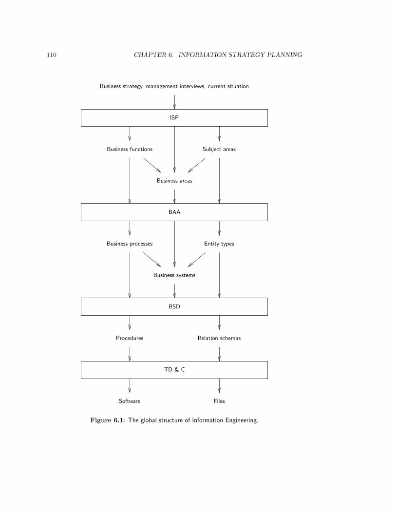
110 CHAPTER 6. INFORMATION STRATEGY PLANNING
ISP
Business strategy, management interviews, current situation
Business functions Subject areas
Business areas
BAA
Business processes Entity types
Business systems
BSD
Procedures Relation schemas
TD & C
Software Files
Figure 6.1: The global structure of Information Engineering.
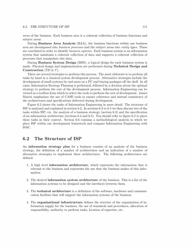
6.2. THE STRUCTURE OF ISP 111
areas of the business. Each business area is a coherent collection of business functions andsubject areas.
During Business Area Analysis (BAA), the business functions within one businessarea are decomposed into business processes and the subject areas into entity types. Theseare correlated in order to identify business systems. Each business system is an informationsystem that maintains a coherent collection of data and supports a coherent collection ofprocesses that manipulate this data.
During Business System Design (BSD), a logical design for each business system ismade. Physical design and implementation are performed during Technical Design andConstruction (TD & C).
There are several strategies to perform this process. The most elaborate is to perform alltasks by hand in a classical system development process. Alternative strategies include thedevelopment of small systems by end-users on a PC and buying packages off the shelf. In allcases, Information Strategy Planning is performed, followed by a decision about the optimalstrategy to perform the rest of the development process. Information Engineering can beviewed as a toolbox from which to select the tools to perform the rest of development. JamesMartin emphasizes the use of CASE tools to ensure coherence and mutual consistency ofthe architectures and specifications delivered during development.
Figure 6.2 shows the tasks of Information Engineering in more detail. The structure ofISP is analyzed and explained in section 6.2. In sections 6.3 to 6.5 we then discuss two of thetasks within ISP, viz. the analysis of a business strategy (section 6.3) and the specificationof an information architecture (sections 6.4 and 6.5). You should refer to figure 6.2 to placethese tasks in their context. Section 6.6 contains a methodological analysis in which weplace ISP within our development framework and compare Information Engineering withISAC.
6.2 The Structure of ISP
An information strategy plan for a business consists of an analysis of the businessstrategy, the definition of a number of architectures and an indication of a number ofalternative strategies to implement these architectures. The following architectures aredefined.
1. A high level information architecture, which represents the information that isrelevant to the business and represents the use that the business makes of this infor-mation.
2. The desired information system architecture of the business. This is a list of theinformation systems to be designed and the interfaces between them.
3. The technical architecture is a definition of the software, hardware and communi-cation facilities that will support the information systems of the business.
4. The organizational infrastructure defines the stucture of the organization of in-formation supply for the business, the use of standards and procedures, allocation ofresponsibility, authority to perform tasks, location of expertise, etc.
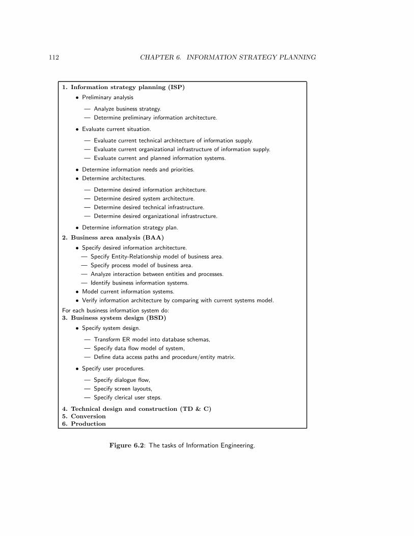
112 CHAPTER 6. INFORMATION STRATEGY PLANNING
1. Information strategy planning (ISP)
• Preliminary analysis
— Analyze business strategy.
— Determine preliminary information architecture.
• Evaluate current situation.
— Evaluate current technical architecture of information supply.
— Evaluate current organizational infrastructure of information supply.
— Evaluate current and planned information systems.
• Determine information needs and priorities.
• Determine architectures.
— Determine desired information architecture.
— Determine desired system architecture.
— Determine desired technical infrastructure.
— Determine desired organizational infrastructure.
• Determine information strategy plan.
2. Business area analysis (BAA)
• Specify desired information architecture.
— Specify Entity-Relationship model of business area.
— Specify process model of business area.
— Analyze interaction between entities and processes.
— Identify business information systems.
• Model current information systems.
• Verify information architecture by comparing with current systems model.
For each business information system do:3. Business system design (BSD)
• Specify system design.
— Transform ER model into database schemas,
— Specify data flow model of system,
— Define data access paths and procedure/entity matrix.
• Specify user procedures.
— Specify dialogue flow,
— Specify screen layouts,
— Specify clerical user steps.
4. Technical design and construction (TD & C)5. Conversion6. Production
Figure 6.2: The tasks of Information Engineering.
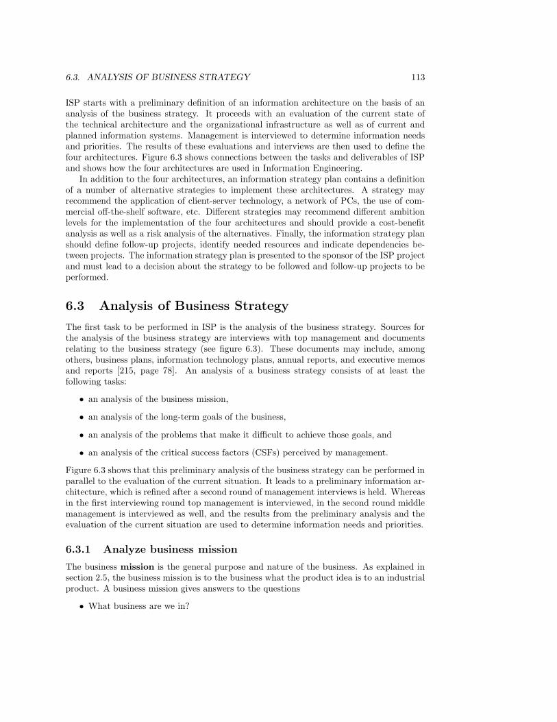
6.3. ANALYSIS OF BUSINESS STRATEGY 113
ISP starts with a preliminary definition of an information architecture on the basis of ananalysis of the business strategy. It proceeds with an evaluation of the current state ofthe technical architecture and the organizational infrastructure as well as of current andplanned information systems. Management is interviewed to determine information needsand priorities. The results of these evaluations and interviews are then used to define thefour architectures. Figure 6.3 shows connections between the tasks and deliverables of ISPand shows how the four architectures are used in Information Engineering.
In addition to the four architectures, an information strategy plan contains a definitionof a number of alternative strategies to implement these architectures. A strategy mayrecommend the application of client-server technology, a network of PCs, the use of com-mercial off-the-shelf software, etc. Different strategies may recommend different ambitionlevels for the implementation of the four architectures and should provide a cost-benefitanalysis as well as a risk analysis of the alternatives. Finally, the information strategy planshould define follow-up projects, identify needed resources and indicate dependencies be-tween projects. The information strategy plan is presented to the sponsor of the ISP projectand must lead to a decision about the strategy to be followed and follow-up projects to beperformed.
6.3 Analysis of Business Strategy
The first task to be performed in ISP is the analysis of the business strategy. Sources forthe analysis of the business strategy are interviews with top management and documentsrelating to the business strategy (see figure 6.3). These documents may include, amongothers, business plans, information technology plans, annual reports, and executive memosand reports [215, page 78]. An analysis of a business strategy consists of at least thefollowing tasks:
• an analysis of the business mission,
• an analysis of the long-term goals of the business,
• an analysis of the problems that make it difficult to achieve those goals, and
• an analysis of the critical success factors (CSFs) perceived by management.
Figure 6.3 shows that this preliminary analysis of the business strategy can be performed inparallel to the evaluation of the current situation. It leads to a preliminary information ar-chitecture, which is refined after a second round of management interviews is held. Whereasin the first interviewing round top management is interviewed, in the second round middlemanagement is interviewed as well, and the results from the preliminary analysis and theevaluation of the current situation are used to determine information needs and priorities.
6.3.1 Analyze business mission
The business mission is the general purpose and nature of the business. As explained insection 2.5, the business mission is to the business what the product idea is to an industrialproduct. A business mission gives answers to the questions
• What business are we in?
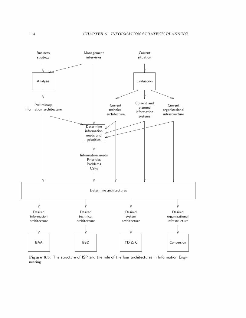
114 CHAPTER 6. INFORMATION STRATEGY PLANNING
Analysis
Businessstrategy
Preliminaryinformation architecture
Determineinformationneeds andpriorities
Managementinterviews
Evaluation
Currentsituation
Currenttechnical
architecture
Current andplanned
informationsystems
Currentorganizationalinfrastructure
Information needsPrioritiesProblems
CSFs
Determine architectures
Desiredorganizationalinfrastructure
Conversion
Desiredsystem
architecture
TD & C
Desiredtechnical
architecture
BSD
Desiredinformationarchitecture
BAA
Figure 6.3: The structure of ISP and the role of the four architectures in Information Engi-neering.

6.3. ANALYSIS OF BUSINESS STRATEGY 115
• The mission of a hospital is the care and treatment of the ill.
• The mission of transport company is the efficient movement of goods from sender toreceiver.
• The mission of a particular software consultancy may be the solution of business prob-lems by means of information technology.
Figure 6.4: Some examples of business missions.
• The goal of a transport company may be to increase its market share. A particularobjective to realize this goal may be to increase market share from 30% to 35% withinthe next 36 months.
• The goal of a software company may be to improve customer relations. An objectiverelated to this goal may be to have all employees follow a particular human relationstraining during the next 12 months.
• The goal of a hardware manufacturer may be to decrease downtime of its products. Anobjective related to this goal is to decrease the number of service calls for its printingequipment to less than one per month on the average within the next 24 months.
Figure 6.5: Examples of business goals and objectives.
• What will our business be?
• What should our business be?
The mission statement gives the reason of existence of the business and describes what theunderlying idea is of the product or service delivered by the business to its environment.Some examples of business missions are given in figure 6.4. The mission statement ofa business may imply success or failure of the business in a changing environment. Forexample, in the early 1960s a Dutch manufacturer of home heating equipment formulatedits mission as the manufacture of coal stoves. When the Netherlands switched to naturalgas heating systems in the late 1960s, this manufacturer went broke [349, page 163]. Hadthe mission been formulated as the manufacture of heating equipment, this might not havehappened.
6.3.2 Analyze business goals and objectives
A goal is a medium to long term result to be achieved by the business. The businessmission is the highest-level goal of the business. Typically, goals are formulated as desirablestates to be reached at an unspecified time in the future. Goals can be made measurableby means of objectives, which are measurable states to be achieved within a specific timeframe. Some examples of goals and objectives are given in figure 6.5.

116 CHAPTER 6. INFORMATION STRATEGY PLANNING
• Achievement of the goal of an increased market share may be inhibited by an inadequateinformation system about competitors.
• The goal of decreased product downtime may be inhibited by an unreliable componentdelivered by a third party.
• The goal of improving customer relations may be inhibited by an inadequate informationsystem about employee performance.
• The goal of having a smaller inventory may be inhibited by the fact that orders tendto be for smaller batches and increase in frequency.
Figure 6.6: Business problems and the goals whose achievement they inhibit.
6.3.3 Analyze business problems
A business problem is a phenomenon that makes the achievement of objectives and goals,and hence of the business mission, more difficult than it has to be. The relation betweenproblems and the goals whose achievement they inhibit can be represented by means ofa problem/goal matrix. Construction of such a matrix for the library case study isstraightforward and is left as an exercise for the reader. Figure 6.6 gives some examples ofbusiness problems and the goals whose achievement they inhibit.
6.3.4 Analyze critical success factors
A critical success factor (CSF) is an area in which, according to management, the busi-ness must perform well. Thus, a CSF is an area of concern to management. If the businessperforms well in this area then (according to management) it is likely that it achieves itsobjectives and if the business performs badly in this area then (according to management)it is likely to fail to reach its objectives. The identification of CSFs is partly a matter ofcognitive style of management and different managers may identify different areas as CSFs.CSF thus bridge the impersonal world of business objectives with the subjective world ofmanagement information. CSFs are identified by management based on experience with thebusiness. One manager of a supermarket listed the following CSFs for a supermarket [285]:
• Product mix
• Inventory
• Sales promotion
• Pricing.
Each CSF should be decomposed into factors for which measurement units and observationprocedures are given. CSFs and their decompositions are thus extremely important to theinformation system developer, for they indicate what the system must provide informationabout.

6.4. DETERMINATION OF INFORMATION ARCHITECTURE 117
Case study. The mission of the library is
to acquire and make available documents containing information that is of use for scientificresearch and education.
An important current library goal is to improve the level of service to library users. Subgoals of thisgoal are
• to increase the availability of documents,
• to provide on-line access to its catalogue and
• to provide on-line access to all university library catalogues in the Netherlands.
Problems that inhibit the achievement of these goals are
• a decreasing budget,
• inefficient budget spending by multiple document and journal acquisitions,
• a large rate of document loss and
• habitual late returns of documents.
Given these goals, the chief librarian identifies the following areas of concern as critical success factorsfor the library:
• The coverage of the scientific fields by the documents possessed by the library.
• The availability of documents to the library members.
• Optimal use of the available budget.
To measure the performance of the library on these CSFs, the librarian will need such data as the number
of borrowing requests placed, through the library’s own circulation desks, to other libraries, and the ratio
between the journals in a particular field present in the library to the total number of journals in that
field. To measure availability, the librarian will need data like the ratio of reservations to borrowings,
the number of missing documents, etc.
6.4 Determination of Information Architecture
An information architecture has four components:
• an entity model of the data relevant for the business,
• a list of relevant business functions, organized hierarchically in a function decomposi-tion tree,
• a definition of dependencies between functions, and
• a function/entity matrix that correlates functions with the entity model.
We show how to define three of these four architecture components in this section. Thespecification of dependencies between functions is not treated here, because this would taketoo much space and would obscure the message of this chapter.
118 CHAPTER 6. INFORMATION STRATEGY PLANNING
6.4.1 The function decomposition tree: structure and meaning
A business function is a group of activities that together support one aspect of furtheringthe mission of the business. A business process is an activity that transforms an inputinto an output and is performed in order to achieve a business function. Where a functionis usually an ongoing activity such as acquire orders or dispatch products, a process is anactivity performed in a particular time interval, and that can be repeated at different timeintervals. Business processes and functions can be organized into a function decompo-sition tree, whose root is the business mission. Descending from the root, we encounterfirst the business functions, and then the business processes. Each higher-level function isrefined into a collection of functions at the next lower level in the tree. A function decompo-sition tree of a system does not make any statement about the decomposition of the systeminto subsystem. To avoid misunderstanding, a more accurate name for the tree would befunction refinement tree, but because the term “function decomposition tree” is widelyused, we will continue using it. The business mission is thus the root of at least two trees:one in which it is decomposed into goals and subgoals (section 6.3) and one in which it isdecomposed into activities (functions and processes).
The function decomposition tree indicates the relationship between what is done in thebusiness and why this is done. The tree thus answers the following questions:
• What is the mission of the business? In other words, why does it exist?
• Which activities must be performed in order to achieve this mission?
• Why is a certain activity performed?
During ISP, the business mission is decomposed to the level of functions. During businessarea analysis, the tree is further decomposed so that it includes all business processes.
Figure 6.7 shows a function decomposition tree of a student administration. The rootof the tree is labeled with the mission of the administration. Described more fully, thismission is
To keep an administration of the educational achievements of students withrespect to the examinations of the faculty.
This mission provides the rationale of all activities below the root in the function decom-position tree. If an administration activity cannot be allocated to a node in the tree, thenthere is no reason to perform it — or more accurately, the mission of the administrationdoes not provide a reason to perform it.
The purpose of a function decomposition tree is to understand what happens in a busi-ness and why. There are many things that are not represented in a function decompositiontree [23]:
• A function decomposition tree does not show mechanism. It does not show howactivities are performed, merely that they are performed. For example, activities inthe tree may be performed manually, mechanically, electronically or mentally.
• A function decomposition tree is independent from the organization structure. Thetree does not show a breakdown of the organization into departments. One departmentmay perform activities at many different nodes, and different parts of the activity atone node may be performed by many different departments.

6.4. DETERMINATION OF INFORMATION ARCHITECTURE 119
Maintain Teaching Administration
PlanningStudent
AdministrationAdministration of
ParticipationEvaluation
MaintainExaminations
MaintainCourses
MaintainPracticals
MakeTimetable
RegisterNew
Students
MaintainStudentData
RegisterTermination
Registrationof Participation
ResultsRegistration
ListParticipants
ListResults
RegisterAdvice
Examinations
Figure 6.7: A function decomposition of a student administration.
120 CHAPTER 6. INFORMATION STRATEGY PLANNING
• A function decomposition tree does not show sequences of activities. The ordering ofnodes from left to right or top to bottom has no meaning and is merely intended toprovide a convenient layout.
• A function decomposition is independent from the jobs people do. Nodes are notjob descriptions. What any one person does may be scattered all over the tree, andconversely different parts of a task at one node may be performed by many differentpeople.
The independence of the function decomposition tree from mechanism, organization struc-ture, procedures and job roles makes it more stable than it would otherwise be, for it willnot be affected by changes in these things. The function decomposition tree is an essen-tial model of the business, i.e. given the business mission, the business should performthe activities in the tree. Changes in implementation mechanisms, job roles, organizationstructures and procedures must all keep the function decomposition tree invariant. Onlychanges in the business mission (or its interpretation by management) should change thetree. It is for this reason that it is important to draw a function decomposition tree beforea change is initiated. The tree serves to represent what must remain constant in the changeprocess.
Given an overall system function and a set of business activities, there are often severaldifferent trees that relate the activities to the overall function and it depends upon theinteraction between the domain specialists and developers what the result will be. Thereis not a single tree that is the “best” model of the business activities. The function of thetree is to serve as a common framework for discussing the information architecture, and tofulfill this function the tree should be geared to the needs of those who use it. The utilityof the tree lies in the fact that it is an extremely simple notation, that requires very littleexplanation to be understood by all stakeholders, and yet conveys a very important messageabout the business, viz. what the business does and why.
Case study. Figure 6.8 shows a function decomposition tree of the library.
6.4.2 The function decomposition tree: construction heuristics
The process of building a function decomposition tree is highly iterative. One may starttop-down (if one knows the system function) or bottom-up (if one knows which activitiesthe system performs), but along the way one is likely to have to backtrack to revise a partof the tree already drawn. A very useful technique to build the first versions of the tree,recommended by Barker and Longman [23], is to use small sticky notelets and write oneactivity on each notelet. The notelets easily stick to a glass wall or to a table surface andcan be moved around quickly as the ideas about the best organization of the tree change.When the tree is stable, and only then, a graphical editor could be used to draw the treeand give it a nice layout.
A useful heuristic for building the tree is to divide the activities in the business into theprimary activity, in which material, energy or information is used to produce a prod-uct or service, and the management activity, in which the primary activity is managed.The primary process can be further divided into activities typical for the different stages ofthe life cycle of the product or service: acquisition of raw material, energy or information,

6.4. DETERMINATION OF INFORMATION ARCHITECTURE 121
Library Mission
Management Primary Process Support
Consultation ofMember
Representatives
BudgetPlanning
Consultationwith
UniversityBoard
StrategicPlanning
ExternalReporting
DocumentAcquisition
DocumentCirculation
Inter-libraryTraffic
DocumentDisposal
Finance
MemberServices
DocumentPreservation
Figure 6.8: A function decomposition of the library.
122 CHAPTER 6. INFORMATION STRATEGY PLANNING
followed by production, distribution, support and disposal of the product or service. Fig-ure 6.9 gives some examples of each of these activities. Typical management activities are:planning of the business organizing it, acquisition of resources to do the business, directingthe work done, and controlling the performance of the work done. Figure 6.10 gives someexamples of each of these activities. We return to management activities in chapter 15,where we discuss the management of the development process.
For each of the identified activities, one can distinguish further activities by describingdifferent aspects. For example, one can describe subactivities related to the financial aspect,the information aspect, the legal aspect, the human aspect, the technological aspect, etc.Acquisition of material from suppliers requires maintaining a database of information aboutpotential and actual suppliers (information aspect), placing orders and making payments(financial aspect), signing contracts (legal aspect), defining interesting job roles (humanaspect), etc.
6.4.3 The entity model: structure and meaning
Each business is interested in a certain part of the world with which it interacts. This isthe Universe of Discourse (UoD) of the business. The UoD of a business may containsuppliers, customers, raw materials, finished products, payments, obligations and rights ofthe business and of its suppliers and customers, etc. As a preparation for making an entitymodel of the UoD, the UoD can be partitioned into subject areas, where a subject areais a topic of interest for the enterprise. Example subject areas for a travel agency are
• Travelers
• Destinations
• Airlines
• Tour operators
• Insurances
Subject areas are named by nouns. Count nouns must be plural (e.g. “Destinations”), massnouns are in the singular (e.g. “Cash”).
Referring to figure 6.3, after the information needs and priorities of the business havebeen determined, the list of subject areas is refined to an ER model of the UoD. An Entity-Relationship model (ER) of a UoD, or entity model for short, is a representation of thetypes of entities and their relationships in the UoD of the business. The phrase “in the UoDof the business” in the previous sentence is synonymous with “of interest to the business”.Without restriction to things of interest for the business, there would be infinitely manyentity types and relationships.
Figure 6.11 shows a fragment of an ER model of three subject areas of a travel agency.An ER model groups entities in the UoD into types. An entity type is represented in anER diagram by a rectangle, labeled by the name of the type. In figure 6.11, AIRPORT isan entity type. Individual airports are instances of this type. A relationship links existingentities of two types; a relationship may relate entities of the same type. The instances of arelationship are called links. For example, a RESERV ATION instance is a link betweena particular TRAV ELER and a particular FLIGHT . Each relationship may be subject
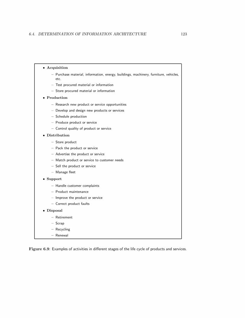
6.4. DETERMINATION OF INFORMATION ARCHITECTURE 123
• Acquisition
– Purchase material, information, energy, buildings, machinery, furniture, vehicles,etc.
– Test procured material or information
– Store procured material or information
• Production
– Research new product or service opportunities
– Develop and design new products or services
– Schedule production
– Produce product or service
– Control quality of product or service
• Distribution
– Store product
– Pack the product or service
– Advertise the product or service
– Match product or service to customer needs
– Sell the product or service
– Manage fleet
• Support
– Handle customer complaints
– Product maintenance
– Improve the product or service
– Correct product faults
• Disposal
– Retirement
– Scrap
– Recycling
– Renewal
Figure 6.9: Examples of activities in different stages of the life cycle of products and services.

124 CHAPTER 6. INFORMATION STRATEGY PLANNING
• Planning
– Analyze environment (competitors, markets, products)
– Identify trends
– Set goals and objectives
– Formulate business strategy
– Determine critical success factors
• Organizing
– Identify and group tasks
– Define organization structures
– Create organizational positions
– Establish qualifications for each position
– Define responsibilities and authority
• Acquisition
– Raise funds
– Purchase equipment
– Recruit staff
– Train staff
– Compensate
– Terminate assignments
• Directing
– Delegate authority
– Motivate personnel
– Coordinate activities
– Facilitate communications
– Resolve conflicts
– Manage changes
– Supervise
• Controlling
– Establish reporting systems
– Develop standards of performance
– Measure results
– Reward and discipline
Figure 6.10: Examples of management activities in a business.

6.4. DETERMINATION OF INFORMATION ARCHITECTURE 125
AIRPORT FLIGHT
PERSON
RESERV ATION
ADDRESSaddress
destination
start
CITYcity
AIRLINEairline
TRAV ELLERS
AIRLINESDESTINATIONS
Figure 6.11: An ER diagram of three subject areas of a travel agency.
to cardinality constraints, which restrict the number of entities that can be linked atany point in time. In this chapter, we only discuss two cardinality constraints. In a many-many relationship R between E1 and E2, any number of existing instances of E1 can belinked to any number of existing instances of E2. A many-many relationship is representedby an undirected line. In a many-one relationship from E1 to E2, each existing instanceof E1 is linked to exactly one existing instance of E2. A many-one relationship from E1 toE2 is represented by an arrow from E1 to E2. For example, in figure 6.11, each FLIGHT
has exactly one destination and one start.There are many different notational conventions for ER models, some of which will be
reviewed in chapter 7. In this book, we use the following conventions.
• The name of an entity type is always a singular noun written in uppercase letters.
• A many-many relationship is represented by an undirected line. If the meaning of therelationship can be expressed by a noun, then this noun can be used as a label of theline, written in uppercase letters. The name of a relationship R between E1 and E2
must be such that the sentence
An R relates an E1 and an E2
is a grammatical sentence (i.e. a syntactically well-formed and semantically mean-ingful sentence). For example, “a RESERV ATION relates a PASSENGER and aFLIGHT” is a grammatical sentence.
• Sometimes, the meaning of a many-many relationship can be expressed by indicatingthe role that a participating entity type plays in the relationship. In these cases, therole name can be written in lowercase letters at the corresponding end point of therelationship line. If instances of E1 play role r in a relationship with E2, then thegrammatical sentence that we can build from this is
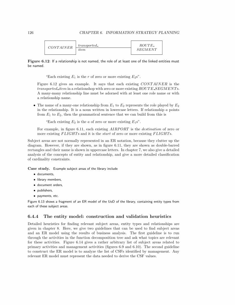
126 CHAPTER 6. INFORMATION STRATEGY PLANNING
CONTAINERROUTE
SEGMENT
transported
item
Figure 6.12: If a relationship is not named, the role of at least one of the linked entities mustbe named.
“Each existing E1 is the r of zero or more existing E2s”.
Figure 6.12 gives an example. It says that each existing CONTAINER is thetransported item in a relationshop with zero or more existing ROUTE SEGMENT s.A many-many relationship line must be adorned with at least one role name or witha relationship name.
• The name of a many-one relationship from E1 to E2 represents the role played by E2
in the relationship. It is a noun written in lowercase letters. If relationship a pointsfrom E1 to E2, then the grammatical sentence that we can build from this is
“Each existing E2 is the a of zero or more existing E1s”.
For example, in figure 6.11, each existing AIRPORT is the destination of zero ormore existing FLIGHT s and it is the start of zero or more existing FLIGHT s.
Subject areas are not normally represented in an ER notation, because they clutter up thediagram. However, if they are shown, as in figure 6.11, they are shown as double-barredrectangles and their name is shown in uppercase letters. In chapter 7, we also give a detailedanalysis of the concepts of entity and relationship, and give a more detailed classificationof cardinality constraints.
Case study. Example subject areas of the library include
• documents,
• library members,
• document orders,
• publishers,
• payments, etc.
Figure 6.13 shows a fragment of an ER model of the UoD of the library, containing entity types from
each of these subject areas.
6.4.4 The entity model: construction and validation heuristics
Detailed heuristics for finding relevant subject areas, entity types and relationships aregiven in chapter 8. Here, we give two guidelines that can be used to find subject areasand an ER model using the results of business analysis. The first guideline is to runthrough the activities in the function decomposition tree and ask what topics are relevantfor these activities. Figure 6.14 gives a rather arbitrary list of subject areas related toprimary activities and management activities (figures 6.9 and 6.10). The second guidelineto construct the ER model is to analyze the list of CSFs identified by management. Anyrelevant ER model must represent the data needed to derive the CSF values.

6.4. DETERMINATION OF INFORMATION ARCHITECTURE 127
PASS MEMBER DOCUMENTIDENTIFI-
CATION
LOAN
ORDER
ordered item
INV OICEorder
PAY MENTinvoice
PUBLISHER
publisher
BUDGET
budget
T ITLE
RESERV ATION title
Figure 6.13: An ER model of some data relevant for the library.
• Suppliers
• Parts
• Orders
• Equipment
• Personnel
• Budgets
• Customers
• Sales
• Products
• Transport
• Complaints
• Results
Figure 6.14: Some example subject areas of a business.

128 CHAPTER 6. INFORMATION STRATEGY PLANNING
Budget planningDocument preservation
Member servicesFinanceInter-library trafficDocument disposal
Document circulationDocument acquisition
PASS R CD
MEMBER R CUD
TITLE C U D
DOCUMENT C U D U U
PAY MENT CD
INV OICE CD
ORDER C UD
PUBLISHER C
BUDGET R CRU
C = Create accessR = Read accessU = Update accessD = Delete access
Figure 6.15: Function/entity matrix for the library.
Case study. The librarian listed the following CSFs:
• The coverage of the scientific fields by the documents possessed by the library.
• The availability of documents to the library members.
• Optimal use of the available budget.
The ER diagram in figure 6.13 can serve as a basis to accommodate the data needed to assess these
factors. For example, these data can be specified as attributes of entity types in the model.
A useful heuristic to validate the ER model is to correlate the subject areas and entitytypes with the activities of the business. This tells us what is the relevance of the subjectareas and entity types for the activities and what is the use that each activity makes of databelonging to the entity types. The correlation can be represented by means of a matrix inwhich all activities are listed along one dimension and all subject areas or entity types alongthe other. An entry in the cell indicates whether the activity creates, uses, updates or deletesdata belonging to the subject area or entity type. The matrix of activities versus subjectareas should be separated from the matrix of activities versus entity types. This gives is twotypes of matrices, the function/subject area matrix and the function/entity matrix.
Case study. Figure 6.15 shows a function/entity matrix for the library. Only the budgeting activity
of the management function is shown in the table. The other activities do not manipulate instances
of the entity types shown. For each function, we indicated the kind of access it has to instances of
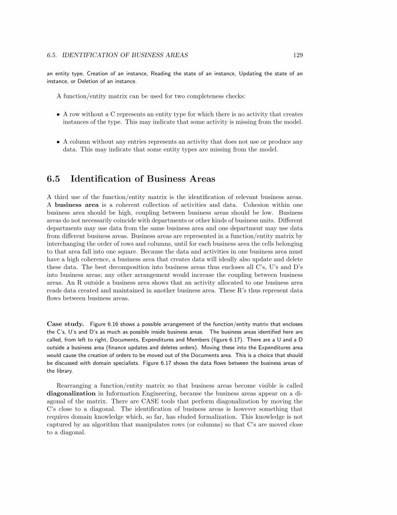
6.5. IDENTIFICATION OF BUSINESS AREAS 129
an entity type, Creation of an instance, Reading the state of an instance, Updating the state of an
instance, or Deletion of an instance.
A function/entity matrix can be used for two completeness checks:
• A row without a C represents an entity type for which there is no activity that createsinstances of the type. This may indicate that some activity is missing from the model.
• A column without any entries represents an activity that does not use or produce anydata. This may indicate that some entity types are missing from the model.
6.5 Identification of Business Areas
A third use of the function/entity matrix is the identification of relevant business areas.A business area is a coherent collection of activities and data. Cohesion within onebusiness area should be high, coupling between business areas should be low. Businessareas do not necessarily coincide with departments or other kinds of business units. Differentdepartments may use data from the same business area and one department may use datafrom different business areas. Business areas are represented in a function/entity matrix byinterchanging the order of rows and columns, until for each business area the cells belongingto that area fall into one square. Because the data and activities in one business area musthave a high coherence, a business area that creates data will ideally also update and deletethese data. The best decomposition into business areas thus encloses all C’s, U’s and D’sinto business areas; any other arrangement would increase the coupling between businessareas. An R outside a business area shows that an activity allocated to one business areareads data created and maintained in another business area. These R’s thus represent dataflows between business areas.
Case study. Figure 6.16 shows a possible arrangement of the function/entity matrix that encloses
the C’s, U’s and D’s as much as possible inside business areas. The business areas identified here are
called, from left to right, Documents, Expenditures and Members (figure 6.17). There are a U and a D
outside a business area (finance updates and deletes orders). Moving these into the Expenditures area
would cause the creation of orders to be moved out of the Documents area. This is a choice that should
be discussed with domain specialists. Figure 6.17 shows the data flows between the business areas of
the library.
Rearranging a function/entity matrix so that business areas become visible is calleddiagonalization in Information Engineering, because the business areas appear on a di-agonal of the matrix. There are CASE tools that perform diagonalization by moving theC’s close to a diagonal. The identification of business areas is however something thatrequires domain knowledge which, so far, has eluded formalization. This knowledge is notcaptured by an algorithm that manipulates rows (or columns) so that C’s are moved closeto a diagonal.
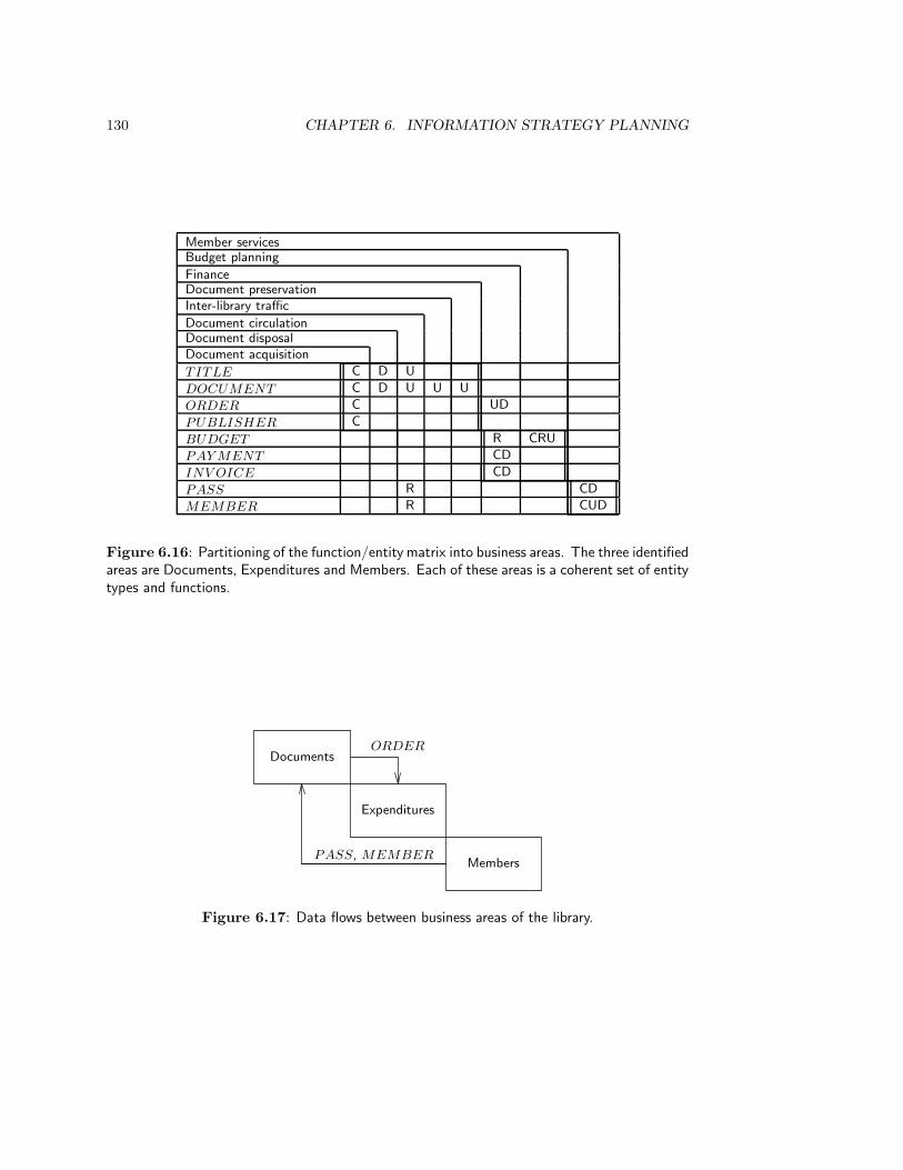
130 CHAPTER 6. INFORMATION STRATEGY PLANNING
Member servicesBudget planning
FinanceDocument preservationInter-library traffic
Document circulationDocument disposalDocument acquisition
TITLE C D U
DOCUMENT C D U U U
ORDER C UD
PUBLISHER C
BUDGET R CRU
PAY MENT CD
INV OICE CD
PASS R CD
MEMBER R CUD
Figure 6.16: Partitioning of the function/entity matrix into business areas. The three identifiedareas are Documents, Expenditures and Members. Each of these areas is a coherent set of entitytypes and functions.
Documents
Expenditures
Members
ORDER
PASS, MEMBER
Figure 6.17: Data flows between business areas of the library.
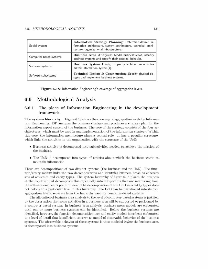
6.6. METHODOLOGICAL ANALYSIS 131
Social systemInformation Strategy Planning: Determine desired in-formation architecture, system architecture, technical archi-tecture, organizational infrastructure.
Computer-based systemsBusiness Area Analysis: Model business areas, identifybusiness systems and specify their external behavior.
Software systemsBusiness System Design: Specify architecture of auto-mated information system(s).
Software subsystemsTechnical Design & Construction: Specify physical de-signs and implement business systems.
Figure 6.18: Information Engineering’s coverage of aggregation levels.
6.6 Methodological Analysis
6.6.1 The place of Information Engineering in the developmentframework
The system hierarchy. Figure 6.18 shows the coverage of aggregation levels by Informa-tion Engineering. ISP analyzes the business strategy and produces a strategy plan for theinformation aspect system of the business. The core of the strategy consists of the four ar-chitectures, which must be used in any implementation of the information strategy. Withinthis core, the information architecture plays a central role. It has a peculiar structure,which links the activities in the organization with the structure of the UoD:
• Business activity is decomposed into subactivities needed to achieve the mission ofthe business.
• The UoD is decomposed into types of entities about which the business wants tomaintain information.
These are decompositions of two distinct systems (the business and its UoD). The func-tion/entity matrix links the two decompositions and identifies business areas as coherentsets of activities and entity types. The system hierarchy of figure 6.18 places the businessat the top level and decomposes this repeatedly into subsystems that are interesting fromthe software engineer’s point of view. The decomposition of the UoD into entity types doesnot belong to a particular level in this hierarchy. The UoD can be partitioned into its ownaggregation levels, separate from the hierarchy used for computer-based systems.
The allocation of business area analysis to the level of computer-based systems is justifiedby the observation that some activities in a business area will be supported or performed bya computer-based system. In business area analysis, business areas models are elaborateduntil one or more business systems can be identified. Before the business systems areidentified, however, the function decomposition tree and entity models have been elaboratedto a level of detail that is sufficient to serve as model of observable behavior of the businesssystems. The observable behavior of these systems is thus modeled before the business areais decomposed into business systems.
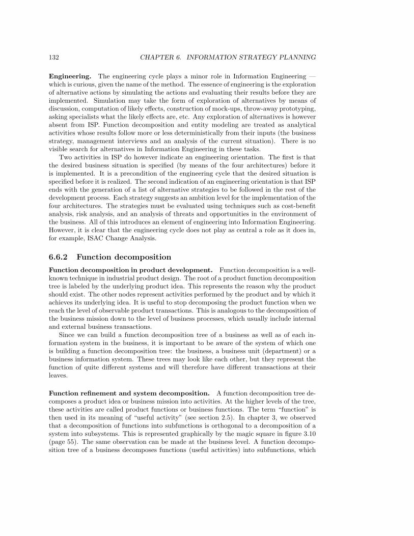
132 CHAPTER 6. INFORMATION STRATEGY PLANNING
Engineering. The engineering cycle plays a minor role in Information Engineering —which is curious, given the name of the method. The essence of engineering is the explorationof alternative actions by simulating the actions and evaluating their results before they areimplemented. Simulation may take the form of exploration of alternatives by means ofdiscussion, computation of likely effects, construction of mock-ups, throw-away prototyping,asking specialists what the likely effects are, etc. Any exploration of alternatives is howeverabsent from ISP. Function decomposition and entity modeling are treated as analyticalactivities whose results follow more or less deterministically from their inputs (the businessstrategy, management interviews and an analysis of the current situation). There is novisible search for alternatives in Information Engineering in these tasks.
Two activities in ISP do however indicate an engineering orientation. The first is thatthe desired business situation is specified (by means of the four architectures) before itis implemented. It is a precondition of the engineering cycle that the desired situation isspecified before it is realized. The second indication of an engineering orientation is that ISPends with the generation of a list of alternative strategies to be followed in the rest of thedevelopment process. Each strategy suggests an ambition level for the implementation of thefour architectures. The strategies must be evaluated using techniques such as cost-benefitanalysis, risk analysis, and an analysis of threats and opportunities in the environment ofthe business. All of this introduces an element of engineering into Information Engineering.However, it is clear that the engineering cycle does not play as central a role as it does in,for example, ISAC Change Analysis.
6.6.2 Function decomposition
Function decomposition in product development. Function decomposition is a well-known technique in industrial product design. The root of a product function decompositiontree is labeled by the underlying product idea. This represents the reason why the productshould exist. The other nodes represent activities performed by the product and by which itachieves its underlying idea. It is useful to stop decomposing the product function when wereach the level of observable product transactions. This is analogous to the decomposition ofthe business mission down to the level of business processes, which usually include internaland external business transactions.
Since we can build a function decomposition tree of a business as well as of each in-formation system in the business, it is important to be aware of the system of which oneis building a function decomposition tree: the business, a business unit (department) or abusiness information system. These trees may look like each other, but they represent thefunction of quite different systems and will therefore have different transactions at theirleaves.
Function refinement and system decomposition. A function decomposition tree de-composes a product idea or business mission into activities. At the higher levels of the tree,these activities are called product functions or business functions. The term “function” isthen used in its meaning of “useful activity” (see section 2.5). In chapter 3, we observedthat a decomposition of functions into subfunctions is orthogonal to a decomposition of asystem into subsystems. This is represented graphically by the magic square in figure 3.10(page 55). The same observation can be made at the business level. A function decompo-sition tree of a business decomposes functions (useful activities) into subfunctions, which
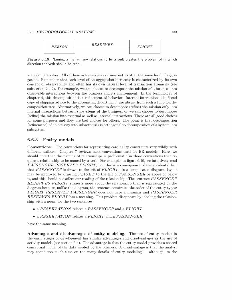
6.6. METHODOLOGICAL ANALYSIS 133
PERSON FLIGHTRESERV ES
Figure 6.19: Naming a many-many relationship by a verb creates the problem of in whichdirection the verb should be read.
are again activities. All of these activities may or may not exist at the same level of aggre-gation. Remember that each level of an aggegation hierarchy is characterized by its ownconcept of observability and often has its own natural level of transaction atomicity (seesubsection 2.4.2). For example, we can choose to decompose the mission of a business intoobservable interactions between the business and its environment. In the terminology ofchapter 4, this decomposition is a refinement of behavior. Internal interactions like “sendcopy of shipping advice to the accounting department” are absent from such a function de-composition tree. Alternatively, we can choose to decompose (refine) the mission only intointernal interactions between subsystems of the business; or we can choose to decompose(refine) the mission into external as well as internal interactions. These are all good choicesfor some purposes and they are bad choices for others. The point is that decomposition(refinement) of an activity into subactivities is orthogonal to decomposition of a system intosubsystem.
6.6.3 Entity models
Conventions. The conventions for representing cardinality constraints vary wildly withdifferent authors. Chapter 7 reviews most conventions used for ER models. Here, weshould note that the naming of relationships is problematic in those conventions that re-quire a relationship to be named by a verb. For example, in figure 6.19, we intuitively readPASSENGER RESERV ES FLIGHT , but this is a consequence of the accidental factthat PASSENGER is drawn to the left of FLIGHT . In a complicated diagram, layoutmay be improved by drawing FLIGHT to the left of PASSENGER or above or belowit, and this should not affect our reading of the relationship. The sentence PASSENGER
RESERV ES FLIGHT suggests more about the relationship than is represented by thediagram because, unlike the diagram, the sentence constrains the order of the entity types:FLIGHT RESERV ES PASSENGER does not have a meaning and PASSENGER
RESERV ES FLIGHT has a meaning. This problem disappears by labeling the relation-ship with a noun, for the two sentences
• a RESERV ATION relates a PASSENGER and a FLIGHT
• a RESERV ATION relates a FLIGHT and a PASSENGER
have the same meaning.
Advantages and disadvantages of entity modeling. The use of entity models inthe early stages of development has similar advantages and disadvantages as the use ofactivity models (see section 5.4). The advantage is that the entity model provides a sharedconceptual model of the data needed by the business. A disadvantage is that the analystmay spend too much time on too many details of entity modeling — although, to the

134 CHAPTER 6. INFORMATION STRATEGY PLANNING
extent that the entity model is more stable than a model of business activities, this timeis not wasted. A second disadvantage of entity modeling is that the model may not beunderstandable by management, which means that it cannot fullfil its role as a means ofcommunication with management.
6.6.4 Information Engineering and ISAC
Norm-driven and problem-driven. A major difference between ISAC and InformationEngineering is that ISAC takes experienced problems as the starting point, while Informa-tion Engineering takes a business strategy as the starting point. Jointly, they cover thepossible starting points for client-oriented development: deterioration of performance withrespect to norms that themselves may be unchanged, and a change of norms with respectto a situation that itself may not have changed. Of course, these two starting points arenot mutually exclusive. Correspondingly, in ISAC Change Analysis one finds tasks in whichthe business goals are analyzed, and in ISP one finds tasks in which business problems areanalyzed.
Given their differences and agreements, it is easy to identify possibilities of combination.Putting both methods in one bag of tools, one can pick and choose among the followingmethods and techniques according to the needs of the situation:
• Analysis of problems and interest groups (ISAC)
• Analysis of problem causes (ISAC)
• Function decomposition (ISP)
• Activity modeling of the current or desired situation (ISAC)
• Entity modeling of the UoD (ISP)
• Linking activities to entity types (ISP)
This list is not complete but does indicate the possibilities for combination.
Function decomposition and activity modeling. Function decomposition trees andISAC activity models are closely related and can be built in a mutually consistent way.Activity models are organized in a hierarchical way which, when function decomposition isused, should correspond to the function decomposition tree. Figure 6.20 shows a part of afunction decomposition tree that shows the hierarchical decomposition relation of the twoactivity models of the library shown in chapter 5 (figures 5.7 and 5.8).
Participation. Just like ISAC, Information Engineering stresses the importance of userparticipation. However, since the intended system users in Information Engineering includetop management, and managers tend to have little time for representative participation,management participation in Information Engineering tends to be of the consultative kind.
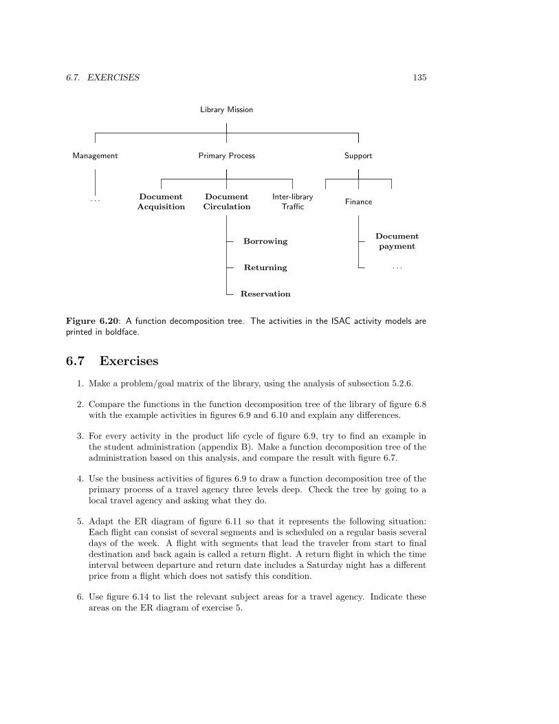
6.7. EXERCISES 135
Library Mission
Management Primary Process Support
· · · DocumentAcquisition
DocumentCirculation
Borrowing
Returning
Reservation
Inter-libraryTraffic
Finance
Documentpayment
· · ·
Figure 6.20: A function decomposition tree. The activities in the ISAC activity models areprinted in boldface.
6.7 Exercises
1. Make a problem/goal matrix of the library, using the analysis of subsection 5.2.6.
2. Compare the functions in the function decomposition tree of the library of figure 6.8with the example activities in figures 6.9 and 6.10 and explain any differences.
3. For every activity in the product life cycle of figure 6.9, try to find an example inthe student administration (appendix B). Make a function decomposition tree of theadministration based on this analysis, and compare the result with figure 6.7.
4. Use the business activities of figures 6.9 to draw a function decomposition tree of theprimary process of a travel agency three levels deep. Check the tree by going to alocal travel agency and asking what they do.
5. Adapt the ER diagram of figure 6.11 so that it represents the following situation:Each flight can consist of several segments and is scheduled on a regular basis severaldays of the week. A flight with segments that lead the traveler from start to finaldestination and back again is called a return flight. A return flight in which the timeinterval between departure and return date includes a Saturday night has a differentprice from a flight which does not satisfy this condition.
6. Use figure 6.14 to list the relevant subject areas for a travel agency. Indicate theseareas on the ER diagram of exercise 5.
136 CHAPTER 6. INFORMATION STRATEGY PLANNING
7. Using the results of exercises 4 and 5, make a function/entity matrix of a travel agencyand identify business areas.
8. Consider the following three models made in ISP: a function decomposition tree, anentity model and a function/entity matrix.
(a) Is making a function decomposition tree a descriptive activity (for which theempirical cycle is the appropriate method) or is it a prescriptive activity (forwhich the engineering cycle is the appropriate method)?
(b) Is making an entity model of the UoD a descriptive or a prescriptive activity?
(c) Given a function decomposition tree and an entity model, is there one uniquefunction/entity matrix that combines the two?
6.8 Bibliographical Remarks
A large number of methods and techniques went into Information Engineering, among whichare Business Systems Planning (BSP), a strategic planning method developed by IBM,Entity-Relationship modeling, and a number of other diagraming techniques. InformationEngineering was developed in the 1970s by Clive Finkelstein and James Martin. A jointbook about Information Engineering was published in 1981 [217]. A year later, a widelycited work by James Martin on methods for strategic data planning appeared [212], whichshould be viewed as part of Information Engineering. In 1989, James Martin publisheda revision of the Martin/Finkelstein volumes [214, 215, 216]. Meanwhile, Finkelstein hadstarted his own company and published a book about his own version of the method also in1989 [103]. This differs considerably from the earlier Martin/Finkelstein version. In additionto Finkelstein’s and Martin’s brands of IE, there is a third version marketed by the ArthurYoung Information Technology Group [72]. This is close to the original Martin/Finkelsteinversion.
In this chapter, James Martin’s version of Information Engineering is described, basedupon Martin’s 1989 description of it [215], course material by James Martin Associates [166],and on a very clear exposition of Information Strategy Planning given by Simons andVerheijen [319].
In addition, use is made of a book on function analysis written by Barker and Long-man [23]. This book is part of a trilogy that describes a method similar to Information Engi-neering, called Case*Method [21, 22, 23]. This method goes back to a comprehensive methodfor data and activity analysis presented by Rosemary Rock-Evans [280, 281, 282, 283].
The list of activities in the product life cycle (figure 6.9) and the list of managementactivities (figure 6.10) are based on similar lists given by Barker and Longman [23], Mar-tin [212], and the list of management activities given by Thayer [342].
Chapter 7
The Entity-RelationshipApproach I: Models
7.1 Introduction
Entity-relationship (ER) modeling is a method for building conceptual models of aUoD. It was introduced by Peter Chen in 1976 as a reaction to the relational data modelingapproach [65] proposed by Ted Codd in 1970 [69]. Relational data modeling was itself areaction to still earlier approaches to the specification of database systems, in which the spec-ification of conceptual data structures was mixed with the specification of implementationstructures. In those earlier approaches, a model that represented entity types and relation-ships in the UoD was not distinguished from a model of access paths and pointer structuresin a computer-based system. The relational approach proposed by Codd eliminates thisproblem by abstracting from implementation structures. However, it also abstracts frommany of the structures present in the UoD: all that is represented in a relational data modelis that certain data items can be grouped together in tuples. As a consequence, relationaldata models are useful high level models of the data stored by a computer-based system,but they are not well-suited to modeling structures present in the UoD of the system. Chenproposed the ER approach as a means to represent the structure of the UoD without at thesame time saying anything about implementation structures in a computer-based system.
There are many versions of the ER approach that disagree about the graphical conven-tions used and about the extensions added to the initial version of the approach presentedby Chen. This chapter ends with a survey of some major graphical conventions and theirrelationship to the convention used in this book. The conventions and concepts definedin this chapter stay close to Chen’s original proposal but avoid a number of ambiguitiespresent in that notation. In sections 7.2 to 7.4, we lay the groundwork by defining enti-ties, attributes, types, existence and identity. In section 7.5 we define relationships andin section 7.6 cardinality constraints. In section 7.7, a very brief introduction to the is a
relationship is given. Section 7.8 contains a methodological analysis of the ER approach.
137
138 CHAPTER 7. THE ENTITY-RELATIONSHIP APPROACH I: MODELS
7.2 Entities, Values and Attributes
7.2.1 ER entities
To distinguish the entity concept in ER modeling from the concept of entity in other model-ing approaches, as in JSD, I will often speak of ER entities instead of just entities. We definean ER entity as any actual or possible part of reality that, if it exists, can be observed.Note that this is identical to the concept of a system given in chapter 2. Consequently, allexamples of systems are examples of entities:
• Physical objects like cars, sticks and stones are ER entities.
• Intangible objects like operating systems, editors and compilers are ER entities.
• Social constructs like organizations, employees, obligations and bank accounts are ERentities.
• Ephemeral objects like events, actions and transactions are ER entities.
• Unobservable things like truth values, numbers and characters are not ER entities, butphysical symbol occurrences used to represent these abstract things are ER entities.
7.2.2 Attributes
Entities are observable, and they therefore have observable properties. For example, aparticular person can be observed to have a weight of 90 kg. In this observation, weightis called an attribute and 90 kg is called an attribute value. More generally, we defineattributes and their values as follows:
• An attribute is a type of non-disturbing observation that can be made of an ERentity.
• An attribute value is a particular instance of an attribute. That is, it is a particularnon-disturbing observation that has been made of an ER entity.
Observing the value of an attribute should not change the attribute value nor the valueof any other entity attribute. Hence, we require attributes to be types of non-disturbingobservations. In database terms, an attribute value is the answer to a query, and queriesshould not change the state of the queried system.
Attribute values represent part of the state of an ER entity. Suppose that a physicalobject has attributes weight, color and shape, then we can represent part of the state ofthe object by a tuple of attribute/value pairs as follows:
〈color : green, weight : 10 kg, shape : cube〉.
7.2.3 Values
Abstract, unobservable things such as numbers are called values in this book. The set ofall possible values is disjoint from the set of all possible ER entities, for the first consistsof unobservable things and the second of observable things. Values are used to representobservations in a system of measures. For example, we say that the weight of an ER entity
7.3. TYPES AND EXISTENCE 139
is 10 kg or that someone is called John. The symbol occurrences “10” and “John” arethemselves observable parts of the world and they are therefore ER entities. Often, ad hocvalues are invented to represent certain system observations. We may invent for examplethe set of values {green, red, blue} to stand for observations of the three colors green, redand blue.
7.2.4 Null values
The use of null values must be avoided as far as possible, because their meaning is unclearand their logic is unknown. Null values are used, among others, to represent the followingthings:
• To indicate that an event has not yet taken place (e.g. termination date has valuenull when termination has not yet occurred).
• To indicate attribute values that are unknown (e.g. birth date has value null).
• To indicate nonexistence of an entity (e.g. no car owner exists). (This would be moreproperly called a null entity.)
• To indicate confidentiality of attribute values (e.g. telephone has a null value when itis secret but is known to exist).
• To indicate inapplicability of attribute values (e.g. maiden name of male employees).
If the same null value is used with all these meanings, then if an attribute value is null,we do not know what it means. Even if we were to disambiguate the null and use, say,nonexistent when we mean that an attribute value is unknown, then the logic of this valueis unknown. How do we count null values with this meaning? If two attributes values areboth null, are these attribute values equal? Similar questions can be asked of the otherpossible meanings of null. Because null values are highly ambiguous and ill-understood,they should be avoided as much as possible, and when they cannot be avoided, be treatedwith special care.
7.3 Types and Existence
7.3.1 Intension and extension
Values and ER entities with similar properties are classified into types according to theproperties they have in common.
• A property of a thing is the contents of any true proposition about that thing.
• A type is a set of properties shared by a set of things.
• The extension of a type is the set of all actual and possible things that share theproperties in the type.
• An element of the extension of a type is called an instance
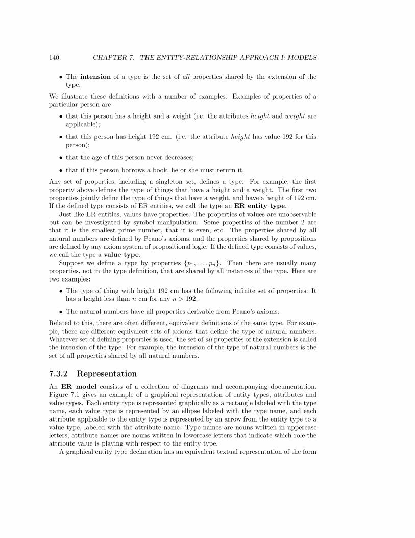
140 CHAPTER 7. THE ENTITY-RELATIONSHIP APPROACH I: MODELS
• The intension of a type is the set of all properties shared by the extension of thetype.
We illustrate these definitions with a number of examples. Examples of properties of aparticular person are
• that this person has a height and a weight (i.e. the attributes height and weight areapplicable);
• that this person has height 192 cm. (i.e. the attribute height has value 192 for thisperson);
• that the age of this person never decreases;
• that if this person borrows a book, he or she must return it.
Any set of properties, including a singleton set, defines a type. For example, the firstproperty above defines the type of things that have a height and a weight. The first twoproperties jointly define the type of things that have a weight, and have a height of 192 cm.If the defined type consists of ER entities, we call the type an ER entity type.
Just like ER entities, values have properties. The properties of values are unobservablebut can be investigated by symbol manipulation. Some properties of the number 2 arethat it is the smallest prime number, that it is even, etc. The properties shared by allnatural numbers are defined by Peano’s axioms, and the properties shared by propositionsare defined by any axiom system of propositional logic. If the defined type consists of values,we call the type a value type.
Suppose we define a type by properties {p1, . . . , pn}. Then there are usually manyproperties, not in the type definition, that are shared by all instances of the type. Here aretwo examples:
• The type of thing with height 192 cm has the following infinite set of properties: Ithas a height less than n cm for any n > 192.
• The natural numbers have all properties derivable from Peano’s axioms.
Related to this, there are often different, equivalent definitions of the same type. For exam-ple, there are different equivalent sets of axioms that define the type of natural numbers.Whatever set of defining properties is used, the set of all properties of the extension is calledthe intension of the type. For example, the intension of the type of natural numbers is theset of all properties shared by all natural numbers.
7.3.2 Representation
An ER model consists of a collection of diagrams and accompanying documentation.Figure 7.1 gives an example of a graphical representation of entity types, attributes andvalue types. Each entity type is represented graphically as a rectangle labeled with the typename, each value type is represented by an ellipse labeled with the type name, and eachattribute applicable to the entity type is represented by an arrow from the entity type to avalue type, labeled with the attribute name. Type names are nouns written in uppercaseletters, attribute names are nouns written in lowercase letters that indicate which role theattribute value is playing with respect to the entity type.
A graphical entity type declaration has an equivalent textual representation of the form

7.3. TYPES AND EXISTENCE 141
PERSON
DATENATURAL
birth dateheight
STRINGname
RATIONAL
weight
STRINGbirth place
PERSON(name : STRING, height : NATURAL, birth date : DATE, birth place :STRING, weight : RATIONAL).
Figure 7.1: Graphical representation of entity types, attributes and value types, and its equiv-alent textual representation.
E(a1 : T1, . . . , an : Tn).
The graphical or textual declaration can be supplemented with a specification of other prop-erties shared by all instances. For example, the PERSON type could have the additionaldefining property that
• all PERSON instances have a weight less than 150 kg.
It is useful to interpret an attribute as a mathematical function from the extension of theentity type to the set of possible attribute values. A mathematical function is a relationbetween two sets, called domain and codomain, such that each element of the domain islinked to at most one element of the codomain. The concept of mathematical function isentirely different from the concept of system function introduced in chapter 2. For example,let ext(PERSON) be the extension of PERSON (i.e. the set of all current and possiblepersons) and ext(NATURAL) the extension of NATURAL (i.e. the set of all naturalnumbers). Then we can view height as a mathematical function
height : ext(PERSON) → ext(NAT ).
The extension of PERSON is called the domain of height and the extension of NATURAL
the codomain of height. By abuse of language, the types PERSON and NATURAL willthemselves also be called domain and codomain of height, respectively. Note that in rela-tional databases, the codomain of an attribute is called the domain of the attribute!
142 CHAPTER 7. THE ENTITY-RELATIONSHIP APPROACH I: MODELS
7.3.3 Existence
The extension of the type of persons is the set of all possible person entities and the extensionof the type of natural numbers is the set of all natural numbers. At any moment, a subsetof the set of all possible persons exists. In subsection 2.2.1, the concept of existence of asystem was equated with the possibility to interact with other existing systems. Since ERentities and systems are the same thing, we also say that an ER entity exists if it is capableof interacting with other ER existing entities. It follows that values do not exist, at leastnot according to the existence concept defined here. Values are unobservable, so they don’tinteract with anything. Of course, symbol occurrences that represent values can exist, i.e.they can be created and destroyed. However, events in the life of a symbol occurrence arenot events in the life of the represented values.
The set of instances of a type that exists in a state of the UoD is called the existenceset of the type in that state of the UoD. Each attribute is only defined for the existence setof its domain. Let us write σ for an arbitrary state of the UoD and extσ(PERSON) forthe existence set of PERSON in state σ. Then extσ(PERSON) ⊂ ext(PERSON), forthe set of existing persons is a subset of the set of all possible persons. The height attributeis only defined for the existence set of PERSON , so that we have
height : extσ(PERSON) → ext(NATURAL).
7.4 Entity Identification
7.4.1 The importance of identification
It is extremely important for value types to be able to test on equality. For example, it isby means of equations like a+ b = b+a that we define the meaning of addition for integers,and it is by means of reductions like 2 + 3 = 5 that we can compute the value of integerexpressions.
Equality is also important for entity types. For each entity type we must define anidentification criterion that tells us when to count two observations of an entity asobservations of the same entity, and when to count them as observations of different entities.Consider the entity type MEMBER in an ER model of the UoD of a library. If we make twoobservations of library members at different times, we can ask if these are observations of thesame member. If, by independent criteria, we know that the same person was observed bothtimes, did we then observe the same member? This depends upon the library regulations.One person may quit being a member and after a while register anew as a member. Inthese two incarnations as a library member, the person will receive a library pass withdifferent identifiers. We will have to look at library regulations to find out whether theyare considered to be one or two member instances.
On the other hand, suppose we do not know whether we have observed the same person ornot. In this case, the answer seems easy: ask for the library pass. If we observe the same passboth times, we observed the same member. However, library members occasionally lose theirpass and then receive a new one, with another identifier than the previous one. This meansthat difference of pass identifiers does not imply that we have observed different persons.Apparently, a careless definition of identification criteria can lead to wrong conclusions.
7.4. ENTITY IDENTIFICATION 143
7.4.2 Identifiers
If computer-based systems represent entities that exist in the UoD, then they must have ameans of representing the identity of entities. In particular, they must be able to do twothings:
• The system must be able to represent different entities that are in the same state.Otherwise, two entities that in one state of the world happen to have the same at-tribute values would be counted as one. Queries about how many entities there arewould be given the wrong answer, and control signals sent out to the UoD could arriveat the wrong entity.
• The system must be able to represent the same entity in different states. Otherwise,a system would not be able to accumulate historical data about an entity. A queryabout the past state of an entity could then not be answered, and a control decisionbased upon the history of an entity could then not be made.
To represent the identity of an entity in the UoD, the computer-based system must use anidentification scheme that assigns a globally unique identifier to each relevant entity inthe UoD. Each identification scheme has a scope of actual and possible entities to whichit assigns identifiers. An identifier is a value that is assigned by the identification schemewhen the entity becomes relevant. The identification scheme must enforce the followingidentifier requirements:
1. Singular reference: An identifier never refers to more than one ER entity. Thisexcludes homonyms. Even if two ER entities are in exactly the same state, andcannot be distinguished, they must still have different identifiers.
2. Unique naming. An entity never has more than one identifier as name. Thisexcludes synonyms.
3. Monotonic designation: Once an identifier denotes an entity, then this identifierwill always denote this entity. The set of identifier-entity pairs in which we pairidentifiers with the ER entity which they name, therefore only grows.
The first two requirements demand that there be a 1-1 correspondence between identifiersand identified entities, and the monotonicity requirement demands that assignments ofidentifiers to entities never be deleted.
Examples of identification schemes are the employee numbering scheme in a company,the student numbering scheme in a university, the serial numbering scheme of industrialproducts, etc. There is no identification scheme that is watertight. All schemes allowviolation of any of the three identifier requirements. Some people manage to have no socialsecurity number, others have two, some social security numbers may be given mistakenlyor fraudulently to two different people, etc. To make the situation more complex, mostentities are within the scope of different identification schemes, and therefore have severaldifferent legally valid identifiers.
Note that an identifier is a value. For example, an employee number is a natural number.One employee number may be represented by many different symbols (e.g. as a naturalnumber in binary notation or as binary coded decimal), but these symbols all representthe same identifier. One such symbol may have many occurrences in different machines (oreven in the same machine), and all these occurrences represent the same identifier.
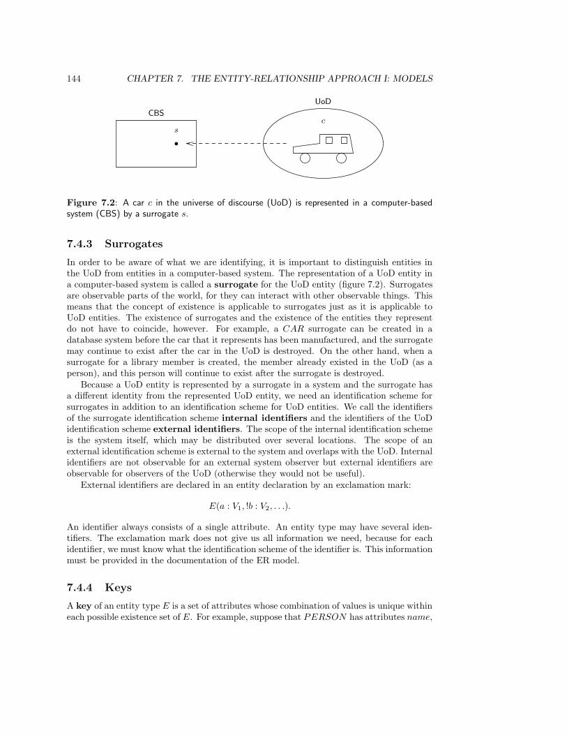
144 CHAPTER 7. THE ENTITY-RELATIONSHIP APPROACH I: MODELS
•
s
CBS
UoD
c
Figure 7.2: A car c in the universe of discourse (UoD) is represented in a computer-basedsystem (CBS) by a surrogate s.
7.4.3 Surrogates
In order to be aware of what we are identifying, it is important to distinguish entities inthe UoD from entities in a computer-based system. The representation of a UoD entity ina computer-based system is called a surrogate for the UoD entity (figure 7.2). Surrogatesare observable parts of the world, for they can interact with other observable things. Thismeans that the concept of existence is applicable to surrogates just as it is applicable toUoD entities. The existence of surrogates and the existence of the entities they representdo not have to coincide, however. For example, a CAR surrogate can be created in adatabase system before the car that it represents has been manufactured, and the surrogatemay continue to exist after the car in the UoD is destroyed. On the other hand, when asurrogate for a library member is created, the member already existed in the UoD (as aperson), and this person will continue to exist after the surrogate is destroyed.
Because a UoD entity is represented by a surrogate in a system and the surrogate hasa different identity from the represented UoD entity, we need an identification scheme forsurrogates in addition to an identification scheme for UoD entities. We call the identifiersof the surrogate identification scheme internal identifiers and the identifiers of the UoDidentification scheme external identifiers. The scope of the internal identification schemeis the system itself, which may be distributed over several locations. The scope of anexternal identification scheme is external to the system and overlaps with the UoD. Internalidentifiers are not observable for an external system observer but external identifiers areobservable for observers of the UoD (otherwise they would not be useful).
External identifiers are declared in an entity declaration by an exclamation mark:
E(a : V1, !b : V2, . . .).
An identifier always consists of a single attribute. An entity type may have several iden-tifiers. The exclamation mark does not give us all information we need, because for eachidentifier, we must know what the identification scheme of the identifier is. This informationmust be provided in the documentation of the ER model.
7.4.4 Keys
A key of an entity type E is a set of attributes whose combination of values is unique withineach possible existence set of E. For example, suppose that PERSON has attributes name,

7.5. RELATIONSHIPS 145
E
V1
V2
V3
V4
d
c
b
!a
!a b c d
1 b1 c1 d1
2 b2 c2 d2
3 b2 c3 d3
swap=⇒
!a b c d
1 b2 c2 d1
2 b1 c1 d2
3 b2 c3 d3
reuse=⇒
!a b c d
1 b2 c2 d1
2 b1 c1 d2
4 b2 c3 d3
Figure 7.3: Key values may be changed and reused. The figure shows three existence sets andtwo state transitions, in the first of which key values are swapped and in the second of which akey is reused.
address, birth date, birth place, age, ssn (social security number). If in each state of theUoD, different existing persons have different values on the combination {name, birth date}then {name, birth date} is a key of PERSON . Keys are often underlined in an entitydeclaration, as in
PERSON(!ssn, name, birth date, . . .).
(For brevity, the codomains of the attributes are not shown.)
It is compatible with the definition of a key that in a state change of an entity, theattribute values of a key change and that after a key value has been used for an existingentity it may be reused for another entity that exists or is created. This distinguishes themfrom identifiers. Figure 7.3 illustrates this. Entity type E is declared as
E(!a, b, c, d).
The three tables represent three existence sets for E. In the state transition from the firstto the second, two entities swap their key values and in the transition from the second tothe third, a key value of a deleted entity is reused for a new entity.
7.5 Relationships
7.5.1 Identity and existence
A link between ER entities is a tuple of ER entities with labeled components. Links arerepresented by writing down a labeled tuple of entity identifiers. An example link is
〈borrowed document : d, borrower : m〉,

146 CHAPTER 7. THE ENTITY-RELATIONSHIP APPROACH I: MODELS
where d and m are identifiers of a document and a library member, respectively. Linkcomponents are not ordered, which means that
〈borrower : m, borrowed document : d〉
is identical to the link listed above. The number of components in a link is called its arity.If the arity is two, the link is called binary, if it is three, it is called ternary. The positionsin the link are identified by the name of the role that the entity plays in the link.
A relationship is a set of properties shared by a set of links — in other words, it isa link type and an individual link is an instance of a relationship. An essential part ofthe definition of a relationship is the specification of which components the instances of therelationship have. This part of the relationship can be specified as follows:
R ⊆ r1 : E1 × · · · × rn : En,
where × is a commutative Cartesian product. The following two declarations are thereforeequivalent:
LOAN ⊆ borrowed document : DOCUMENT × borrower : MEMBER andLOAN ⊆ borrower : MEMBER × borrowed document : DOCUMENT .
A link is an observable part of the UoD and hence an ER entity. We will follow the usualway of speaking and talk of links and entities as if links are not a special kind of entity.However, note that just like any other kind of ER entity, links can have attributes. We candeclare the attributes of links in the same way as we declare attributes of entity types:
R(a1 : V1, . . . , a : m : Vm).
Thus, a relationship declaration consists of at least two parts: a specification of the rela-tionship components and a specification of relationship attributes. A possible third partconsists of all other properties of the relationship instances. For example, every LOAN
instance may have the property that the borrowed document is less than 100 years old.Every link has the dependent identity property, which says that the identity of the
link is the labeled tuple of identities of its components. Consequently, the identifier of a linkis a labeled tuple of identifiers of component identifiers. This has the important consequencethat a relationship cannot link the same entities twice at the same time but it can link themtwice at different times. For example, there cannot exist two occurrences of
〈borrowed document : 123, borrower : 567〉
at the same time, because the equality of these identifiers means that the identified linksare equal. This is reasonable, because one member cannot borrow the same document twicesimultaneously. However, an occurrence of 〈borrowed document : 123, borrower : 567〉 canexist for a while, disappear, and then reappear to exist for another while. Again, this isa reasonable model of reality. If this is not what the modeler wants, then the relationshipshould be replaced by an entity type with its own identifier.
Every existing link is also required to satisfy the component existence assump-tion that all its components exist. This is reasonable, for an observation of a link mayrequire an observation of any of its components. So if the LOAN existence set contains〈borrowed document : 123, borrower : 567〉 as an element, then the DOCUMENT exis-tence set contains 123 and the MEMBER existence set contains 567 as element. The
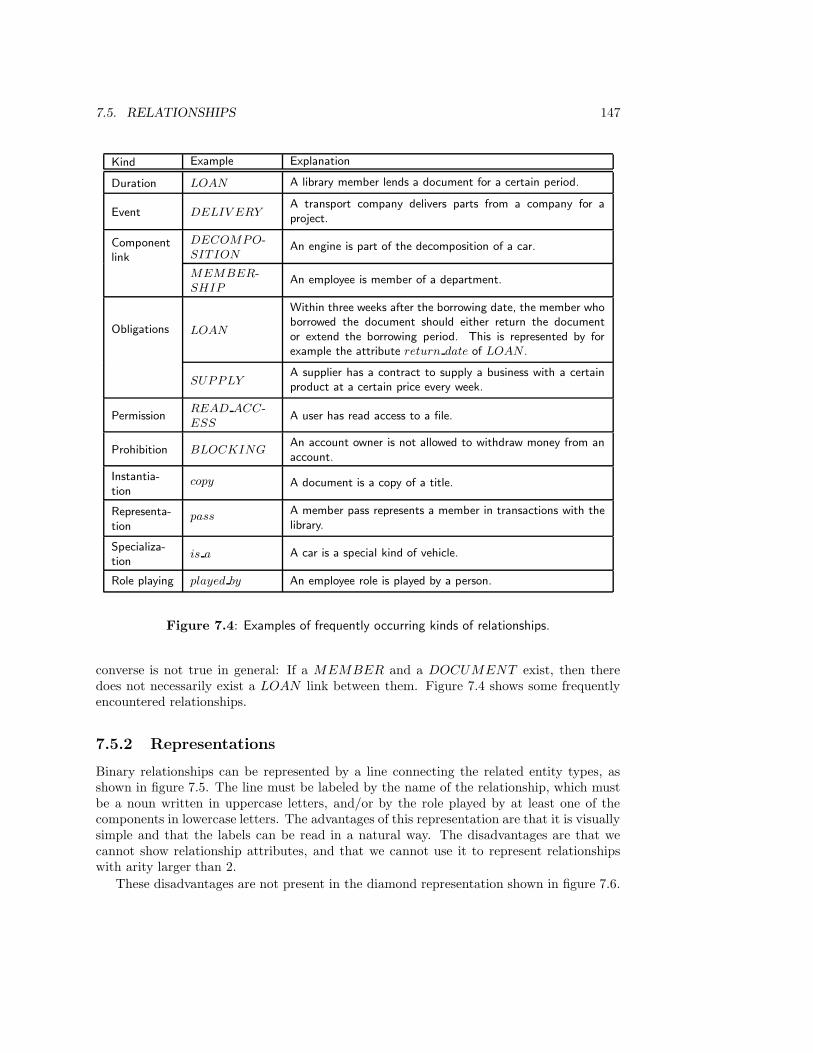
7.5. RELATIONSHIPS 147
Kind Example Explanation
Duration LOAN A library member lends a document for a certain period.
Event DELIV ERYA transport company delivers parts from a company for aproject.
Componentlink
DECOMPO-SITION
An engine is part of the decomposition of a car.
MEMBER-SHIP
An employee is member of a department.
Obligations LOAN
Within three weeks after the borrowing date, the member whoborrowed the document should either return the documentor extend the borrowing period. This is represented by forexample the attribute return date of LOAN .
SUPPLYA supplier has a contract to supply a business with a certainproduct at a certain price every week.
PermissionREAD ACC-ESS
A user has read access to a file.
Prohibition BLOCKINGAn account owner is not allowed to withdraw money from anaccount.
Instantia-tion
copy A document is a copy of a title.
Representa-tion
passA member pass represents a member in transactions with thelibrary.
Specializa-tion
is a A car is a special kind of vehicle.
Role playing played by An employee role is played by a person.
Figure 7.4: Examples of frequently occurring kinds of relationships.
converse is not true in general: If a MEMBER and a DOCUMENT exist, then theredoes not necessarily exist a LOAN link between them. Figure 7.4 shows some frequentlyencountered relationships.
7.5.2 Representations
Binary relationships can be represented by a line connecting the related entity types, asshown in figure 7.5. The line must be labeled by the name of the relationship, which mustbe a noun written in uppercase letters, and/or by the role played by at least one of thecomponents in lowercase letters. The advantages of this representation are that it is visuallysimple and that the labels can be read in a natural way. The disadvantages are that wecannot show relationship attributes, and that we cannot use it to represent relationshipswith arity larger than 2.
These disadvantages are not present in the diamond representation shown in figure 7.6.
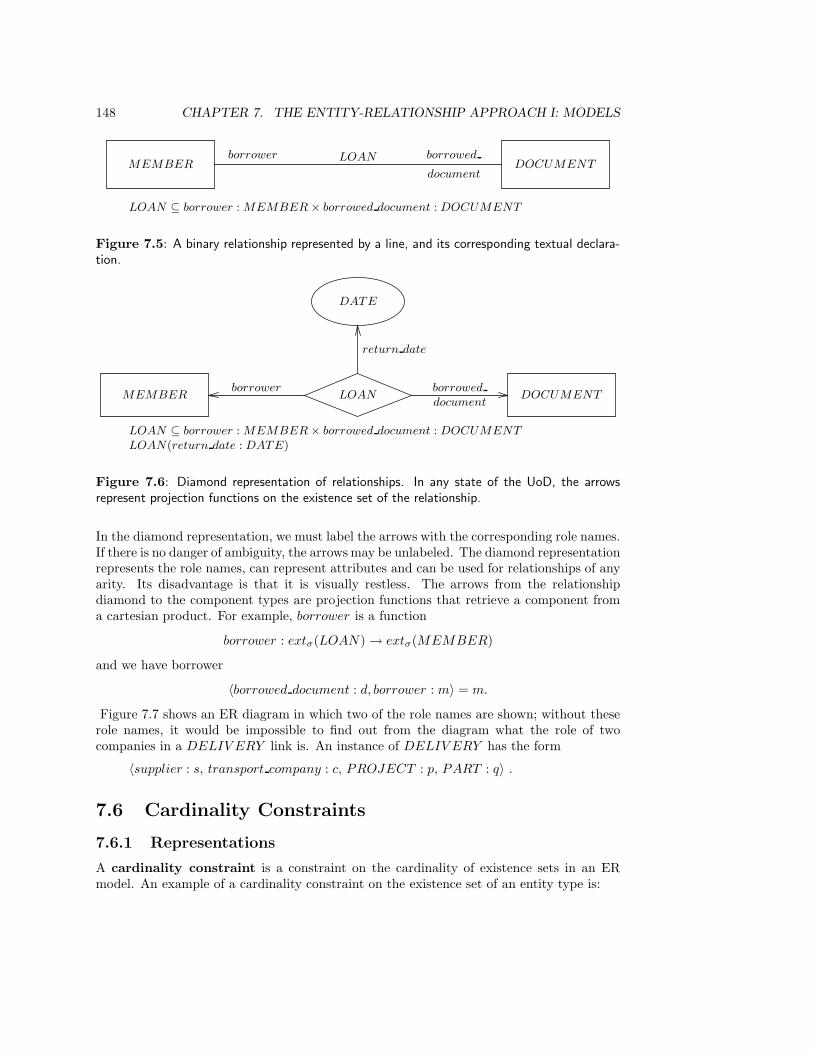
148 CHAPTER 7. THE ENTITY-RELATIONSHIP APPROACH I: MODELS
MEMBER DOCUMENTLOANborrower borrowed
document
LOAN ⊆ borrower : MEMBER × borrowed document : DOCUMENT
Figure 7.5: A binary relationship represented by a line, and its corresponding textual declara-tion.
MEMBER LOAN DOCUMENT
DATE
return date
borrower borrowed
document
LOAN ⊆ borrower : MEMBER × borrowed document : DOCUMENT
LOAN(return date : DATE)
Figure 7.6: Diamond representation of relationships. In any state of the UoD, the arrowsrepresent projection functions on the existence set of the relationship.
In the diamond representation, we must label the arrows with the corresponding role names.If there is no danger of ambiguity, the arrows may be unlabeled. The diamond representationrepresents the role names, can represent attributes and can be used for relationships of anyarity. Its disadvantage is that it is visually restless. The arrows from the relationshipdiamond to the component types are projection functions that retrieve a component froma cartesian product. For example, borrower is a function
borrower : extσ(LOAN) → extσ(MEMBER)
and we have borrower
〈borrowed document : d, borrower : m〉 = m.
Figure 7.7 shows an ER diagram in which two of the role names are shown; without theserole names, it would be impossible to find out from the diagram what the role of twocompanies in a DELIV ERY link is. An instance of DELIV ERY has the form
〈supplier : s, transport company : c, PROJECT : p, PART : q〉 .
7.6 Cardinality Constraints
7.6.1 Representations
A cardinality constraint is a constraint on the cardinality of existence sets in an ERmodel. An example of a cardinality constraint on the existence set of an entity type is:
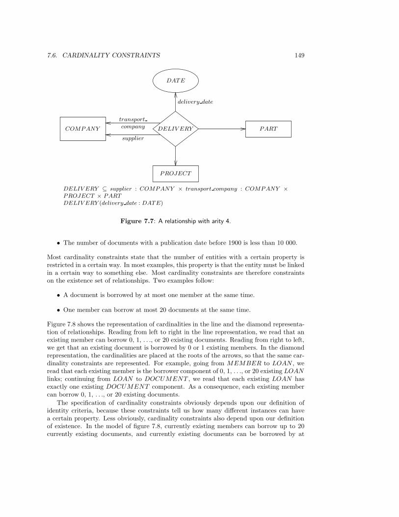
7.6. CARDINALITY CONSTRAINTS 149
COMPANY DELIV ERY
PROJECT
PART
DATE
transport
company
supplier
delivery date
DELIV ERY ⊆ supplier : COMPANY × transport company : COMPANY ×PROJECT × PART
DELIV ERY (delivery date : DATE)
Figure 7.7: A relationship with arity 4.
• The number of documents with a publication date before 1900 is less than 10 000.
Most cardinality constraints state that the number of entities with a certain property isrestricted in a certain way. In most examples, this property is that the entity must be linkedin a certain way to something else. Most cardinality constraints are therefore constraintson the existence set of relationships. Two examples follow:
• A document is borrowed by at most one member at the same time.
• One member can borrow at most 20 documents at the same time.
Figure 7.8 shows the representation of cardinalities in the line and the diamond representa-tion of relationships. Reading from left to right in the line representation, we read that anexisting member can borrow 0, 1, . . ., or 20 existing documents. Reading from right to left,we get that an existing document is borrowed by 0 or 1 existing members. In the diamondrepresentation, the cardinalities are placed at the roots of the arrows, so that the same car-dinality constraints are represented. For example, going from MEMBER to LOAN , weread that each existing member is the borrower component of 0, 1, . . ., or 20 existing LOAN
links; continuing from LOAN to DOCUMENT , we read that each existing LOAN hasexactly one existing DOCUMENT component. As a consequence, each existing membercan borrow 0, 1, . . ., or 20 existing documents.
The specification of cardinality constraints obviously depends upon our definition ofidentity criteria, because these constraints tell us how many different instances can havea certain property. Less obviously, cardinality constraints also depend upon our definitionof existence. In the model of figure 7.8, currently existing members can borrow up to 20currently existing documents, and currently existing documents can be borrowed by at

150 CHAPTER 7. THE ENTITY-RELATIONSHIP APPROACH I: MODELS
MEMBER LOAN DOCUMENTborrower
{0, 1}{0, . . ., 20}
MEMBER DOCUMENTborrower
{0, 1}{0, . . ., 20}
Figure 7.8: Relationship cardinalities. In the diamond representation, the cardinalities areplaced at the roots of the arrows.
Cardinality set is represented as
{0, 1} 0, 1{1} 1{1, 2, . . .} ≥ 1{0, 1, 2, 3, . . .} (Omitted from diagram.){0, . . . , n} ≤ n
{n, n + 1, . . .} ≥ n
Figure 7.9: Frequently occurring cardinality constraints.
most one currently existing member. This is true in the UoD, but if we turn to a computer-based system, the situation may be different. For example, in a historical database system,all LOAN instances are stored even after the loan in the UoD has ceased to exist. Inthat database system, one DOCUMENT surrogate may be related to any number ofMEMBER surrogates through different LOAN links. The model of figure 7.8 would notbe a valid representation of this situation.
7.6.2 Special cardinalities
Cardinality constraints can always be represented in a diagram by sets of natural numbers.A number of common cardinality sets are represented in a simpler way without the curlybrackets, as shown in figure 7.9. For example, in figure 7.10, each existing order has atleast one existing order line and each existing order line belongs to exactly one existingorder. An existing order line is for exactly one existing product, but an existing productcan occur in any number of existing order lines, including 0. This cardinality informationalso gives us some information about existence constraints: an order cannot exist without atleast one existing order line, and an existing order line cannot exist without a correspondingexisting order. An order line cannot exist without a corresponding existing product, but aproduct can very well exist without being ordered for. The relationship between ORDER
and ORDER LINE is often called a master-detail relationship. All global informationsuch as customer address and order number is attached to ORDER (the master), and alldetail information is attached to ORDER LINE instances.

7.6. CARDINALITY CONSTRAINTS 151
ORDERORDER
LINEPRODUCT
1 ≥ 1 1
DATE NATURAL
order date quantity
Figure 7.10: A master-detail relationship between ORDER and ORDER LINE.
DOCUMENT PUBLISHERPUBLI-CATION
0, 1
DOCUMENT PUBLISHERPUBLI-CATION
0, 1
DOCUMENT PUBLISHERpublisher
0
Figure 7.11: Representations of partial many-one relationship, also called partial functions.
For some of the special cardinalities shown in the table above, we can use an arrowrepresentation as an alternative to the line and diamond representations. In the followingparagraphs, we give a number of examples.
Many-one relationships
Figure 7.11 shows three representations of a partial many-one relationship, also called apartial function. A partial many-one relationship from DOCUMENT to PUBLISHER
relates each existing document to at most one existing publisher. The function is partialbecause there are documents that have no publisher. In general, in each state σ of theworld, a partial many-one relationship from E1 to E2 is a partial function
extσ(E1) → ext σ(E2).
The partiality is represented in the arrow representation by writing a 0 through the headof the arrow in the diagram. It is customary to drop the adjective “partial”, but we willnot follow this custom.
Figure 7.12 shows three representations of a total many-one relationship, also calleda total function. A total many-one relationship from DOCUMENT to TITLE relateseach existing document to exactly one existing TITLE. The function is total because each

152 CHAPTER 7. THE ENTITY-RELATIONSHIP APPROACH I: MODELS
DOCUMENT TITLEcopy title
1
DOCUMENT TITLEINSTAN -TIATION
copy title1
DOCUMENT TITLEtitle
Figure 7.12: Representations of a total many-one relationship type (also called total function).
existing document has a title. In general, in any state σ of the world, a total many-onerelationship from E1 to E2 is a total function extσ(E1) → ext σ(E2). A master-detailrelationship is always a total many-one function from detail to master.
Independently from the distinction between partial and total many-one relationships,we can distinguish injective and surjective many-one relationships. Figure 7.13 shows threerepresentations of an injective many-one relationship, also called an injective function.The diagram says that each existing manager manages at most one existing department.This means that different existing departments are managed by different existing managers.This is the distinguishing feature of injective many-one relationship types: if E1 has aninjective many-one relationship to E2, then different existing instances of E1 cannot berelated to the same instance of E2.
Finally, figure 7.14 shows three representations of a surjective many-one relationship(which happens to be total), also called a surjective function. The diagram says thateach existing university has at least one existing faculty. This means that the functionassigning universities to faculties goes onto the existence set of UNIV ERSITY : there isno university that does not participate in the DECOMPOSITION link with at least onefaculty. In general, if E1 has a surjective many-one relationship R to E2, then instance ofE2 cannot exist without participating in R.
One-one relationships
In addition to many-one relationships, we are interested in one-one and in many-manyrelationships. A relationship is called partial one-one if it has cardinality 0, 1 at one orboth sides. If both sides have cardinality 1, then we call it a total one-one or a bijectivefunction. Figure 7.15 shows three representations of a total one-one relationship.
Many-many relationships
Any binary relationship that is not many-one or one-one is called many-many. Figure 7.16shows two representations of a many-many relationship. Note that by the component exis-
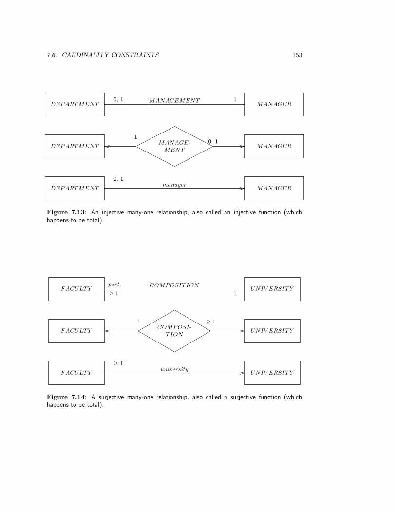
7.6. CARDINALITY CONSTRAINTS 153
DEPARTMENT MANAGERMANAGEMENT 10, 1
DEPARTMENT MANAGERMANAGE-
MENT
10, 1
DEPARTMENT MANAGERmanager
0, 1
Figure 7.13: An injective many-one relationship, also called an injective function (whichhappens to be total).
FACULTY UNIV ERSITYpart COMPOSITION
1≥ 1
FACULTY UNIV ERSITYCOMPOSI-
TION
1 ≥ 1
FACULTY UNIV ERSITYuniversity
≥ 1
Figure 7.14: A surjective many-one relationship, also called a surjective function (whichhappens to be total).

154 CHAPTER 7. THE ENTITY-RELATIONSHIP APPROACH I: MODELS
DEPARTMENT MANAGEMENTMANAGER
11
DEPARTMENT MANAGERMANAGE-
MENT
1 1
DEPARTMENT MANAGERMANAGEMENT
Figure 7.15: A total one-one relationship (also called a bijective function).
TEACHER COURSETEACHING
≤ 2≤ 3
TEACHER COURSETEACH-
ING
≤ 2 ≤ 3
Figure 7.16: Two representations of a many-many relationship.
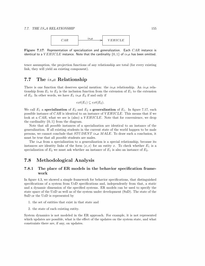
7.7. THE IS A RELATIONSHIP 155
CAR V EHICLEis a
Figure 7.17: Representation of specialization and generalization. Each CAR instance isidentical to a V EHICLE instance. Note that the cardinality {0, 1} of is a has been omitted.
tence assumption, the projection functions of any relationship are total (for every existinglink, they will yield an existing component).
7.7 The is a Relationship
There is one function that deserves special mention: the is a relationship. An is a rela-tionship from E1 to E2 is the inclusion function from the extension of E1 to the extensionof E2. In other words, we have E1 is a E2 if and only if
ext(E1) ⊆ ext(E2).
We call E1 a specialization of E2 and E2 a generalization of E1. In figure 7.17, eachpossible instance of CAR is identical to an instance of V EHICLE. This means that if welook at a CAR, what we see is (also) a V EHICLE. Note that for convenience, we dropthe cardinality {0, 1} from the diagram.
Note that all possible instances of a specialization are identical to an instance of thegeneralization. If all existing students in the current state of the world happen to be malepersons, we cannot conclude that STUDENT is a MALE. To draw such a conclusion, itmust be true that all possible students are males.
The is a from a specialization to a generalization is a special relationship, because itsinstances are identity links of the form 〈x, x〉 for an entity x. To check whether E1 is aspecialization of E2 we must ask whether an instance of E1 is also an instance of E2.
7.8 Methodological Analysis
7.8.1 The place of ER models in the behavior specification frame-work
In figure 4.3, we showed a simple framework for behavior specifications, that distinguishedspecifications of a system from UoD specifications and, independently from that, a staticand a dynamic dimension of the specified systems. ER models can be used to specify thestate space of the UoD as well as of the system under development (SuD). The state of theSuD or the UoD is represented by
1. the set of entities that exist in that state and
2. the state of each existing entity.
System dynamics is not modeled in the ER approach. For example, it is not representedwhich updates are possible, what is the effect of the updates on the system state, and whatconstraints there are, if any, on updates.
156 CHAPTER 7. THE ENTITY-RELATIONSHIP APPROACH I: MODELS
7.8.2 Cardinality constraints
There are many cardinality constraints that are not expressible as cardinality constraintson the existence set of relationships but are nevertheless relevant:
• Constraints on the maximum and average number of existing instances of an entityor relationship.
• If R is a relationship from E1 to E2, then we can give the average number of instancesof E2 linked by R to an existing instance of E1.
• Constraints on the frequency with which entities or links are created, deleted or up-dated.
These constraints are often regarded as constraints on the implementation of the SuD, butthis is not necessarily the case. All of the above constraints have a meaningful interpretationin the UoD of the system.
7.8.3 Constraints on the UoD and constraints on the system
ER models can represent the state space of the SuD or the UoD of the SuD. We saw thatthere is an important difference in the meaning of the statement “an instance of E exists”when interpreted as a statement about the UoD and when interpreted as a statement aboutthe SuD. A UoD instance of E can exist even if no system instance of E (i.e. a surrogate)exists and vice versa.
The difference is even more dramatic when we look at the meaning of cardinality con-straints. Take the statement
• A member has at most one LOAN link to the same document at the same time.
Interpreted as a statement about the UoD, this is an analytical truth that follows from themeaning of the words used in it. Assuming that the statement is interpreted in the normalway, it is impossible that it is falsified by a state of the UoD. On the other hand, interpretedas a statement about a system that represents a UoD, it is a constraint on the valid statesof that system. It is quite possible that the system contains several LOAN links betweenthe same member and the same document surrogate at the same time. Take as a secondexample the statement
• A member has at most 10 000 LOAN links to documents at the same time.
(This statement is implied by the constraint that a member has at most 20 LOAN linksto documents at the same time. If a member cannot borrow more than 20 documents, heor she cannot borrow more than 10 000 documents.) As a statement about the UoD, thisstatement is always true. However, its truth does not follow from the meaning of the wordsused in it, but from observations of the UoD. We have never observed a falsification of thisstatement in the UoD and we can safely assume that we never will observe a falsification inthe UoD. On the other hand, interpreted as a statement about the SuD, it is a constraint onthe valid states of that system. It is quite possible that the system contains more than 10000 LOAN links between a member surrogate and document surrogates at the same time.
Let us call statements that are true in all states of a system regularities of the system.The above two statements are examples of regularities about the UoD but thethere are also
7.9. SUMMARY 157
regularities that apply to the SuD. For example all laws of mechanics and electronics areregularities in the behavior of the system.
Regularities must be constrasted with norms, which are statements that we would like tobe true of a system, but that may be violated. The very same statement may be a regularitywhen interpreted in the UoD but a norm when interpreted in the SuD. For example, the twoexample statements used above are regularities in the UoD but they are norms for the SuD.The name “cardinality constraint” for those two statements is therefore not accurate. Amore accurate term would be cardinality statement. Depending upon our interpretation,a cardinality statement could be a cardinality regularity in the UoD or a cardinalityconstraint on the UoD or on the SuD. However, unless explicitly stated otherwise, we willfollow accepted usage and use the term “cardinality constraint” for cardinality regularitiesas well.
An interesting methodological consequence of this analysis is that a good justification ofinterpreting a sentence as a norm for a computer-based system is that the sentence expressesa regularity in the UoD of that system. Because the system represents its UoD, we knowthat if the system falsifies the sentence, it cannot be in a state that represents a UoD state.Of course, there are many other good justifications for interpreting a sentence as a normfor the system. For example all product objectives are norms for the system because theyhelp in realizing business goals.
The UoD is also subject to norms. Take the following example statement:
• A borrowed document must be returned within three weeks of the borrowing date.
This is a norm for the UoD that can easily be falsified by the UoD. Such a falsification mustbe represented by the system, and therefore cannot be treated as a norm for the system.Indeed, an important function of the system is precisely to represent these violations andsignal them to library personnel. There are also UoD norms that are translated into systemnorms. Take the following example:
• A member has at most 20 LOAN links to documents at the same time.
This is a norm for the UoD that can easily be falsified. If this norm is not effectively enforcedby the library, the system may validly represent 21 LOAN links between a member anddocuments at the same time. However, an important means to enforce this norm is to letthe system refuse to register a borrowing if this would result in a violation of this constraint.Thus, this UoD norm is translated into a system norm. These two examples show that UoDnorms may or may not be translated into system norms. Thus, it is not a good justificationof interpreting a sentence as a norm for a computer-based system that the sentence expressesa norm for the UoD of that system.
7.9 Summary
The set of all possible things is partitioned into ER entities, which are observable partsof the UoD, and values, which are unobservable. The concept of an ER entity is thusthe same as that of a system defined in chapter 2. ER entities have attributes, which aretypes of non-disturbing observations, and attributes have values, which represent possibleobservations of the ER entity. ER entities and values are instances of types. A type is the
158 CHAPTER 7. THE ENTITY-RELATIONSHIP APPROACH I: MODELS
set of properties shared by its instances. ER entities may be related through links. Thetype of a link is called a relationship.
An ER model may represent the state space of a computer-based system or of its UoD.Instances of a type may exist in the UoD or in the system; in the second case, they arecalled surrogates for UoD instances.
An identifier of an entity type is an attribute that has different values for differentinstances, always has the same value for the same instance, and that is never changed.Links have no independent identity nor an independent existence. The identity of a linkis the tuple of identities of its components. A link can only exist if its component ERentities exist. Relationships may represent part-of relations, events, durations, permissions,obligations, etc.
UoD instances (entities or links) are identified by an external identifier, which is visiblefor the user and assigned by some external authority. Surrogates are identified by an internalidentifier, which is invisible to the user and assigned by the system itself. A combinationof attributes whose values are unique on existing ER entities of a type in each state of theworld is called a key of that type. Key values may change from time to time, and key valuesmay also be reused.
Cardinality constraints of relationship R limit the set of existing ER entities relatedwith each other through instances of R. By means of cardinalities we can distinguish many-one, one-one and many-many relationships. For the first two kinds of relationships, we candistinguish partial, total, injective and surjective variants.
A special kind of relationship is the is a function. It is the inclusion function from theextension of a specialization to the extension of a generalization. To test if a relationship isan is a relationship, we must test whether each instance of the specialization is identical toan instance of the generalization.
ER models can be used to represent the state space of a computer-based system orof its UoD. The existence of a UoD entity need not coincide in time with the existenceof its surrogate in the system. Cardinality constraints should be more accurately calledcardinality statements. A statement that expresses a regularity about the UoD can be usedas a constraint on the system. A sentence that expresses a constraint on the UoD mayor may not be interpreted as a constraint on the system. This depends upon the desiredfunctions of the system.
7.10 Exercises
1. Discuss possible identification criteria for DOCUMENT , TITLE and JOURNAL.
2. Add cardinality constraints to the diagram of figure 6.11 interpreted first as a modelof the UoD, and next as a model of the system. In both cases, motivate your choiceof constraints.
3. Draw ER diagrams of the example relationships in figure 7.4. Include cardinalityconstraints for the case that the relationship is interpreted in the UoD, and for thecase that the relationship is interpreted in the system. In both cases, motivate yourchoice of constraints.
4. Consider figure 7.7. One of the following two constraints cannot be expressed as acardinality constraint in the diagram. Which one? Explain your answer.

7.11. BIBLIOGRAPHICAL REMARKS 159
(a) A supplier cannot deliver parts to more than two projects.
(b) A supplier cannot deliver the same part to more than two projects.
5. We can use the is a relationship to eliminate null values of the type not applicable.Explain how this can be done.
6. A diagram containing a partial function from E1 to E2 can always be replaced by anequivalent diagram containing only total functions. Explain how this can be done.
7. Suppose that we allow relations to be components of other relations. Use this constructto change the model in figure 7.7 so that, without using null values, we can representthe situation in which a transport company has not yet been selected for the delivery,but the supplier, part and project are selected, as well as the situation in which thetransport company has been selected.
8. Change the model in figure 7.6 so that historical information about loans can bemaintained. What should be the cardinality constraints in this new model?
9. What is the difference between the referential integrity constraint in relational data-base theory and the component existence constraint defined in this chapter?
10. There is a connection between many–many relationships and the fourth normal formof relational database theory. Explain this connection.
11. Some of the following sentences can be interpreted as sentences about the UoD orsentences about a database system. In the first case, they can be interpreted as con-straints or as regularities, in the second case, they must be interpreted as constraints.For each sentence, answer the following questions:
(a) Can it be interpreted as a regularity in the UoD?
(b) If so, what are the consequences of interpreting it as a constraint on the system?
(c) Can the sentence be interpreted as a constraint on the UoD?
(d) If so, what are the consequences of interpreting it as a constraint on the system?
Answer these questions for the following sentences.
• Less then 100 students follow course CS101 every year.
• Course CS100 is a prerequisite for course CS101.
• Students always follow CS100 before they follow CS101.
7.11 Bibliographical Remarks
Models of UoD semantics. The ER approach is not the only modeling method thatproposed a level of modeling above that of the relational model. In addition to the ERapproach, Nijssen developed NIAM [243, 244] (Nijssen’s Information Analysis Method),also known as the binary relationship method. NIAM has evolved into what is nowoften called a fact-based approach or a role modeling approach. Another influentialapproach stemming from the mid-70s is the study of aggregation and generalization struc-tures in UoD models by Smith and Smith [320, 321], who used techniques from artificialintelligence to add more semantics to data models.

160 CHAPTER 7. THE ENTITY-RELATIONSHIP APPROACH I: MODELS
Introductions to ER modeling. The ER approach originates with Chen’s 1976 pa-per [65]. The International Conference on the Entity-Relationship Approach to SystemsAnalysis and Design has been held since 1980 [64]. Navathe and Elmasri [94] give a goodintroduction in two chapters. A good book-length introduction is given by Batini, Ceri andNavathe [25]. This includes integration with data flow models and transformation of ERmodels into relational, network and hierarchical models. Teory [338] has a less wide scopeand concentrates on a method of implementing an ER model into a relational databasesystem. Rosemary Rock-Evans [280, 281] gives a very elaborate and practical introductionto ER modeling and its place in the system development life cycle.
Different definitions of “ER entity.” There is no universally accepted definition of“entity” in the ER approach. The ambiguity can in most cases be resolved if we ask whether“entity” is used to refer to a type or to an individual, and whether it is used to refer tosomething in the system or in the UoD. This gives four possible meanings of “entity,” all ofwhich occur in the literature.
1. Individual in the UoD. Chen [65, page 10] defines an entity as “a ‘thing’ which can bedistinctly identified.” Elmasri and Navathe [94, page 40] define an entity as “a ‘thing’in the real world with independent existence.”
2. An individual in the system. Elmasri and Navathe [94, page 42] talk about entitiesas if they exist in the database system: “A database will usually contain groups ofentities that are similar.”
3. A type in the UoD. Batini, Ceri and Navathe [25, page 31] say that “entities representclasses of real-world objects.” Instances of this type are called “entity occurrences”.
4. A type in the system. Storey and Goldstein [328, page 307] define an entity as “a‘thing’ of interest in a database, for example STUDENT .” An entity occurrence isnow a record in the database system.
A fifth meaning is also sometimes used, illustrated by the following quotation from Chen [65]:“Let e denote an entity which exists in our minds · · ·” I use the following terms for thesedifferent concepts.
Entity concept Term used in this book
1. An individual in the represented UoD. ER entity, system.
2. An individual in the database system.Symbol, data item, ER entity, surrogate,system.
3. A type in the represented UoD. ER entity type, system type.
4. A type in the database system.Data type, ER entity type, surrogatetype, system type.
5. An individual mental concept. —
Entities, identity and surrogates The concept of identity is discussed in the contextof object-oriented programming by Khoshafian and Copeland [178]. Some of these ideas goback to a paper by Hall, Owlett and Todd [134], who introduced the concept of the surrogate.Surrogates are also used by Codd in RM/T [70]. A clear discussion of the concept of identity

7.11. BIBLIOGRAPHICAL REMARKS 161
EMPLOY EEEMPLOY −
MENT
≥ 1DEPARTMENT
Figure 7.18: Mandatory participation in a link.
in object-oriented databases and models is given by Kent [176, 177]. The concept of identityas presented in this chapter comes from Wieringa and De Jonge [365]. An interesting paperwhich also argues for the need to distinguish objects from values is MacLennan [207].
Mandatory (total) and optional (partial) participation. It is customary to distin-guish mandatory from optional participation of an entity in a link. For example, in fig-ure 7.18, EMPLOY EE participates mandatorily in EMPLOY MENT and DEPART -MENT participates optionally in EMPLOY MENT . This is because an employeecannot exist without participating in at least one existing EMPLOY MENT instance.In the terminology of this chapter, the projection function from EMPLOY MENT toEMPLOY EE is surjective. An alternative terminology often used is that EMPLOY EE
participates totally in EMPLOY MENT and DEPARTMENT participates partiallyin EMPLOY MENT . I refrain from using this terminology because it does not add any-thing to what we can already express and because it may confuse things by using “total”in the meaning of “surjective”.
Differences in graphical representation techniques. There is a lot of difference ingraphical representation techniques within the ER approach. Figure 7.19 shows some al-ternative ways to depict many-one cardinality of a binary relationship. Using diamonds forrelationships, a commonly used convention is the one at the bottom of figure 7.20. Anotherconvention used is to limit cardinality sets to closed intervals, which are then represented bytheir lower and upper bounds (figure 7.21). Most confusing are the alternative conventionsfor contingent participation in a relationship, shown in figure 7.22. The bottom two con-ventions represent, equivalently, that each E1 may be related to one or more E2. They putthe may at the E1 side, which distributes the representation of the cardinality constraintover two places.
The technique used in this book is motivated by the fact that in using it, all arrows ina diagram represent functions and all cardinalities are denoted and interpreted in a single,uniform way. This allows borrowing the terminology from mathematics about partial, total,injective, surjective and bijective functions, which have clear definitions and known proper-ties. It also facilitates implementation because functions from entity types to entity typescan always be represented by pointer-like constructs like location-independent surrogatereferences. Functions from entity types to value types are always represented by attributevalues. Using arrows instead of undirected lines also indicates in which direction we haveto read the names along the arrows. Finally, the representation technique used here putsthe cardinalities at the place where they most naturally belong. This is seen when you tryto represent cardinalities for a relationship with arity greater than 2, using the techniquesof figure 7.20. Only the top representation, which is the one used in this book, scales upnaturally to relationships of higher arity.
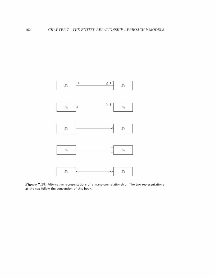
162 CHAPTER 7. THE ENTITY-RELATIONSHIP APPROACH I: MODELS
E1 E2
1 ≥ 1
E1 E2
≥ 1
E1 E2
E1 E2
E1 E2
Figure 7.19: Alternative representations of a many-one relationship. The two representationsat the top follow the convention of this book.
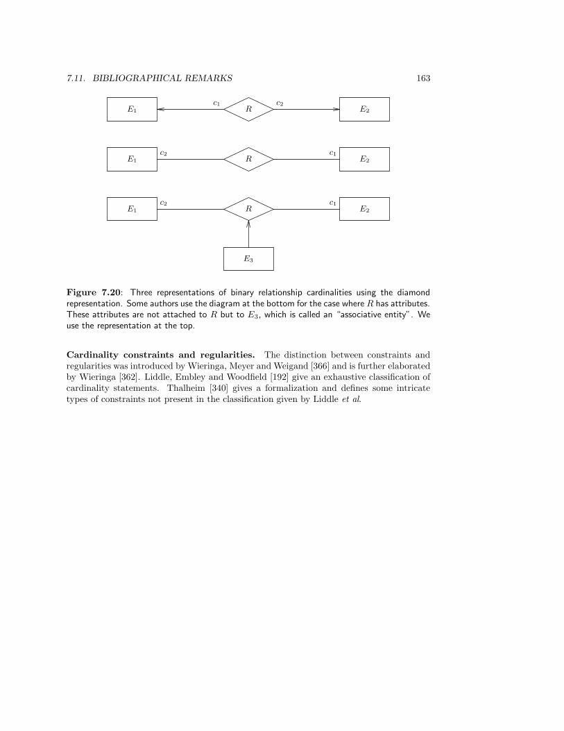
7.11. BIBLIOGRAPHICAL REMARKS 163
E1 Rc2
E2
c1
E1 Rc2
E2
c1
E1 Rc2
E2
c1
E3
Figure 7.20: Three representations of binary relationship cardinalities using the diamondrepresentation. Some authors use the diagram at the bottom for the case where R has attributes.These attributes are not attached to R but to E3, which is called an “associative entity”. Weuse the representation at the top.
Cardinality constraints and regularities. The distinction between constraints andregularities was introduced by Wieringa, Meyer and Weigand [366] and is further elaboratedby Wieringa [362]. Liddle, Embley and Woodfield [192] give an exhaustive classification ofcardinality statements. Thalheim [340] gives a formalization and defines some intricatetypes of constraints not present in the classification given by Liddle et al.
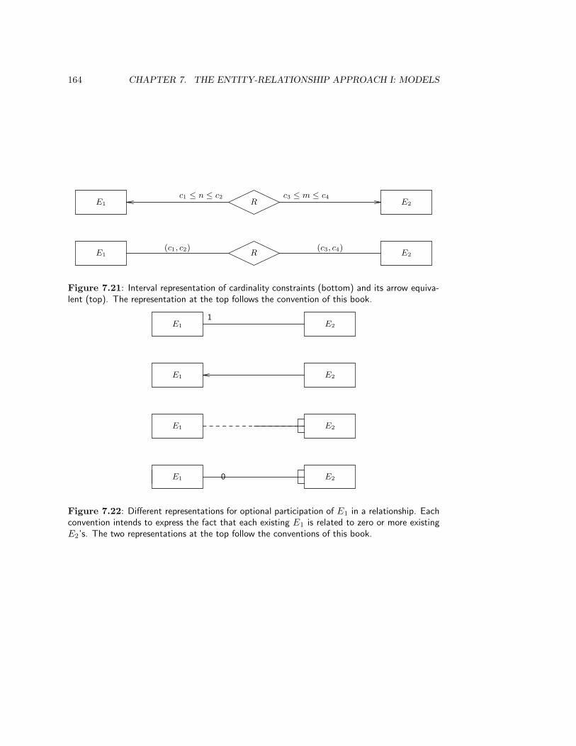
164 CHAPTER 7. THE ENTITY-RELATIONSHIP APPROACH I: MODELS
E1 R E2
c1 ≤ n ≤ c2 c3 ≤ m ≤ c4
E1 R E2
(c1, c2) (c3, c4)
Figure 7.21: Interval representation of cardinality constraints (bottom) and its arrow equiva-lent (top). The representation at the top follows the convention of this book.
E1 E2
1
E1 E2
E1 E2
E1 E20
Figure 7.22: Different representations for optional participation of E1 in a relationship. Eachconvention intends to express the fact that each existing E1 is related to zero or more existingE2’s. The two representations at the top follow the conventions of this book.

Chapter 8
The Entity-RelationshipApproach II: Methods
8.1 Introduction
There is no single method for ER modeling, but there are many heuristics proposed bymany different researchers. In this chapter, we gather a number of these heuristics andgroup them into two classes: heuristics for finding an ER model (section 8.2) and heuristicsfor evaluating an ER model (section 8.3). In section 8.4, we show how an ER model of adatabase system can be transformed into a relational database schema. ER models can bemade of a computer-based system or of its UoD. Because the first can only be found byway of the second, we restrict ourselves to finding an ER model of the UoD of a system.Section 8.5 contains a methodological analysis of the heuristics discussed in this chapter.
8.2 Methods to Find an ER Model
There are four methods to find an ER model of a UoD (figure 8.1).
• In entity analysis of transactions, required system transactions are analyzed onwhich data they manipulate.
• In natural language analysis, one analyzes natural language sentences on wordsthat indicate entity types and relationships.
• In form analysis, forms used within a business are analyzed to discover the structureof the data entered on these forms.
• In record analysis, record declarations in a database schema are analyzed to discovertheir structure.
In addition, if one has built a number of ER models of different parts of the same UoD,using one or more of the above methods, then one can merge these different ER models intoa more complex model of that UoD. This is called view integration. In this chapter, we
165

166 CHAPTER 8. THE ENTITY-RELATIONSHIP APPROACH II: METHODS
Functiondecomposition
tree,Scenarios
TransactionsTransaction/use
tableEntity
analysis
Transaction decompositiontable
Naturallanguage
text
Elementarysentences
ER model ofUoD or SuD
Naturallanguageanalysis
Recorddeclarations
Recordanalysis
Forms
Formanalysis
Figure 8.1: A road map of methods to find an ER model.
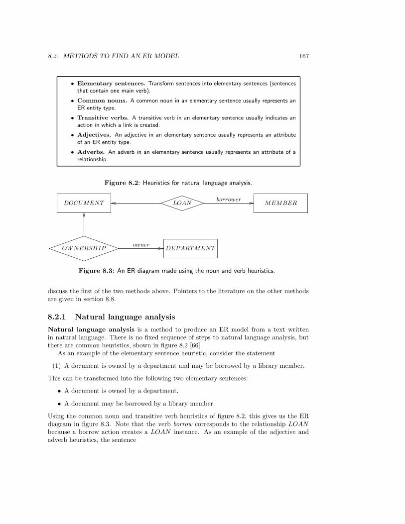
8.2. METHODS TO FIND AN ER MODEL 167
• Elementary sentences. Transform sentences into elementary sentences (sentencesthat contain one main verb).
• Common nouns. A common noun in an elementary sentence usually represents anER entity type.
• Transitive verbs. A transitive verb in an elementary sentence usually indicates anaction in which a link is created.
• Adjectives. An adjective in an elementary sentence usually represents an attributeof an ER entity type.
• Adverbs. An adverb in an elementary sentence usually represents an attribute of arelationship.
Figure 8.2: Heuristics for natural language analysis.
DOCUMENT MEMBERLOAN
DEPARTMENTOWNERSHIP
borrower
owner
Figure 8.3: An ER diagram made using the noun and verb heuristics.
discuss the first of the two methods above. Pointers to the literature on the other methodsare given in section 8.8.
8.2.1 Natural language analysis
Natural language analysis is a method to produce an ER model from a text writtenin natural language. There is no fixed sequence of steps to natural language analysis, butthere are common heuristics, shown in figure 8.2 [66].
As an example of the elementary sentence heuristic, consider the statement
(1) A document is owned by a department and may be borrowed by a library member.
This can be transformed into the following two elementary sentences:
• A document is owned by a department.
• A document may be borrowed by a library member.
Using the common noun and transitive verb heuristics of figure 8.2, this gives us the ERdiagram in figure 8.3. Note that the verb borrow corresponds to the relationship LOAN
because a borrow action creates a LOAN instance. As an example of the adjective andadverb heuristics, the sentence
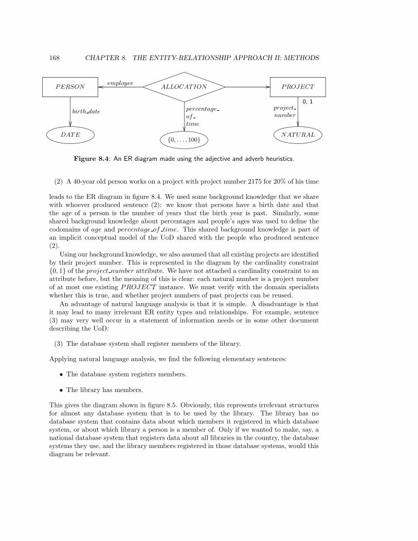
168 CHAPTER 8. THE ENTITY-RELATIONSHIP APPROACH II: METHODS
PERSON PROJECTALLOCATIONemployee
DATE{0, . . . , 100}
NATURAL
birth date percentage
of
time
project
number
0, 1
Figure 8.4: An ER diagram made using the adjective and adverb heuristics.
(2) A 40-year old person works on a project with project number 2175 for 20% of his time
leads to the ER diagram in figure 8.4. We used some background knowledge that we sharewith whoever produced sentence (2): we know that persons have a birth date and thatthe age of a person is the number of years that the birth year is past. Similarly, someshared background knowledge about percentages and people’s ages was used to define thecodomains of age and percentage of time. This shared background knowledge is part ofan implicit conceptual model of the UoD shared with the people who produced sentence(2).
Using our background knowledge, we also assumed that all existing projects are identifiedby their project number. This is represented in the diagram by the cardinality constraint{0, 1} of the project number attribute. We have not attached a cardinality constraint to anattribute before, but the meaning of this is clear: each natural number is a project numberof at most one existing PROJECT instance. We must verify with the domain specialistswhether this is true, and whether project numbers of past projects can be reused.
An advantage of natural language analysis is that it is simple. A disadvantage is thatit may lead to many irrelevant ER entity types and relationships. For example, sentence(3) may very well occur in a statement of information needs or in some other documentdescribing the UoD:
(3) The database system shall register members of the library.
Applying natural language analysis, we find the following elementary sentences:
• The database system registers members.
• The library has members.
This gives the diagram shown in figure 8.5. Obviously, this represents irrelevant structuresfor almost any database system that is to be used by the library. The library has nodatabase system that contains data about which members it registered in which databasesystem, or about which library a person is a member of. Only if we wanted to make, say, anational database system that registers data about all libraries in the country, the databasesystems they use, and the library members registered in those database systems, would thisdiagram be relevant.
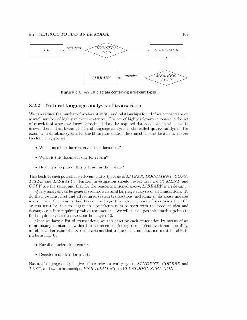
8.2. METHODS TO FIND AN ER MODEL 169
DBS CUSTOMERREGISTRA-
TION
LIBRARYMEMBER-
SHIP
registrar
member
Figure 8.5: An ER diagram containing irrelevant types.
8.2.2 Natural language analysis of transactions
We can reduce the number of irrelevant entity and relationships found if we concentrate ona small number of highly relevant sentences. One set of highly relevant sentences is the setof queries of which we know beforehand that the required database system will have toanswer them. This brand of natural language analysis is also called query analysis. Forexample, a database system for the library circulation desk must at least be able to answerthe following queries:
• Which members have reserved this document?
• When is this document due for return?
• How many copies of this title are in the library?
This leads to such potentially relevant entity types as MEMBER, DOCUMENT , COPY ,TITLE and LIBRARY . Further investigation should reveal that DOCUMENT andCOPY are the same, and that for the reason mentioned above, LIBRARY is irrelevant.
Query analysis can be generalized into a natural language analysis of all transactions. Todo that, we must first find all required system transactions, including all database updatesand queries. One way to find this out is to go through a number of scenarios that thesystem must be able to engage in. Another way is to start with the product idea anddecompose it into required product transactions. We will list all possible starting points tofind required system transactions in chapter 13.
Once we have a list of transactions, we can describe each transaction by means of anelementary sentence, which is a sentence consisting of a subject, verb and, possibly,an object. For example, two transactions that a student administration must be able toperform may be
• Enroll a student in a course.
• Register a student for a test.
Natural language analysis gives three relevant entity types, STUDENT , COURSE andTEST , and two relationships, ENROLLMENT and TEST REGISTRATION .

170 CHAPTER 8. THE ENTITY-RELATIONSHIP APPROACH II: METHODS
8.2.3 Entity analysis of transactions
A second way to analyze transactions, which gives more information, is entity analysis oftransactions. In this method, we write down for each transaction which entities or links arecreated, read, updated or deleted. We write this down in a table called a transaction/usetable and use this as a source for entity types and relationships to put in an ER diagram.We illustrate this method by applying it to the student administration.
Figure 8.6 shows part of a function decomposition tree of a student administration. Wefocus on the middle branch, because the leaves of this branch are transactions that theadministration must be able to perform. Figure 8.7 shows a transaction/use table thatlists the entities or links created, read, updated or deleted in the administration by thetransaction. Because of its format, the table can be easily constructed line by line. Notethat the we focus upon data created, read, updated or deleted in the system itself. This isbecause we are analyzing transactions of the system, and these transactions have access tothe data in the system, not to their entities and links in the UoD. For example, the systemdoes not “read” the course in the UoD (whatever that may mean) but a course surrogate inthe system. Nevertheless, this data represents entities or links in the UoD, and we thereforeend up with a model of the UoD.
Building a transaction/use table is an iterative process in which we may have to back-track several times. It is likely to be performed in parallel with drawing an ER diagram ofthe contents of the table so far, because the diagram allows us to keep track of the contentsof the table more easily.
The transaction/use table is equivalent to the transaction decomposition tableshown in figure 8.8. The transaction decomposition table is called a process/entity ma-trix in Information Engineering, because transactions are called processes there; it is amore detailed version of the function/entity matrix made in ISP (chapter 6). The reasonfor calling it a transaction decomposition table is that each transaction is decomposed intoactions performed on entities or links. The transaction decomposition table plays a centralrole in the integration of methods in chapter 13.
Figure 8.9 shows the ER diagram obtained from the transaction/use table. Inclusion ofthe attributes of the entity types and relationships would clutter up the diagram, so thesehave been added as textual declarations. Note the null value in two of the attribute resulttypes. The reason they appear here is that TEST REG and PRACTICAL REG standfor registration events, whereas the result attributes are attributes of two other events thatoccur later, viz. doing the test and finishing the practical work. The ER method does nothelp in distinguishing these events. We return to this in chapter 13, where we discuss theintegration of the ER method with Jackson System Development.
Building an ER diagram from a transaction/use table is not automatic. It requiresanalysis of the meaning of the names of the entity types and relationships. For example,by choosing to represent some types as relationships, decisions about (structured) identityhave been made. As before, the modeler is not likely to get it right the first time.
8.2.4 Case study: the library
In this section, natural language analysis and entity analysis of transactions are used tofind an ER model of the UoD of the circulation department of the library described inappendix B. We start with an entity analysis of transactions.
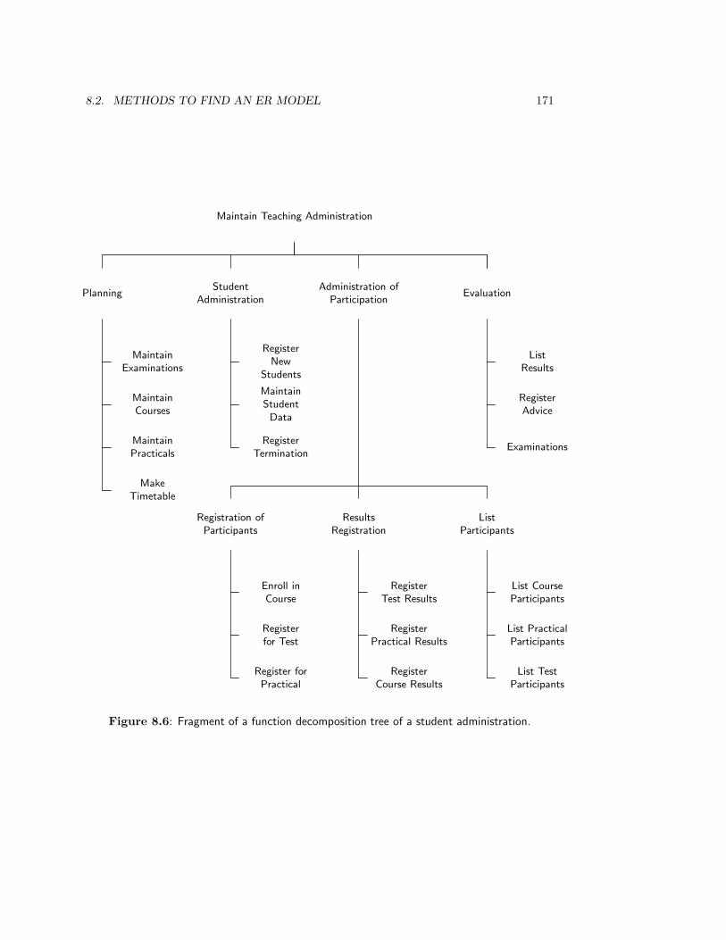
8.2. METHODS TO FIND AN ER MODEL 171
Maintain Teaching Administration
PlanningStudent
AdministrationAdministration of
ParticipationEvaluation
MaintainExaminations
MaintainCourses
MaintainPracticals
MakeTimetable
RegisterNew
Students
MaintainStudentData
RegisterTermination
ListResults
RegisterAdvice
Examinations
Registration ofParticipants
ResultsRegistration
ListParticipants
Enroll inCourse
Registerfor Test
Register forPractical
RegisterTest Results
RegisterPractical Results
RegisterCourse Results
List CourseParticipants
List PracticalParticipants
List TestParticipants
Figure 8.6: Fragment of a function decomposition tree of a student administration.
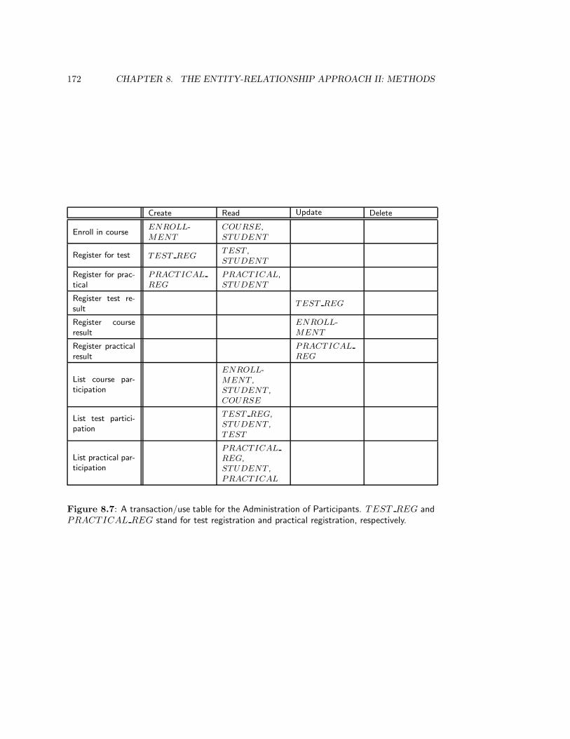
172 CHAPTER 8. THE ENTITY-RELATIONSHIP APPROACH II: METHODS
Create Read Update Delete
Enroll in courseENROLL-MENT
COURSE,STUDENT
Register for test TEST REGTEST ,STUDENT
Register for prac-tical
PRACTICAL
REG
PRACTICAL,STUDENT
Register test re-sult
TEST REG
Register courseresult
ENROLL-MENT
Register practicalresult
PRACTICAL
REG
List course par-ticipation
ENROLL-MENT ,STUDENT ,COURSE
List test partici-pation
TEST REG,STUDENT ,TEST
List practical par-ticipation
PRACTICAL
REG,STUDENT ,PRACTICAL
Figure 8.7: A transaction/use table for the Administration of Participants. TEST REG andPRACTICAL REG stand for test registration and practical registration, respectively.
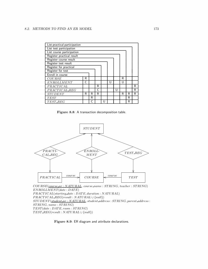
8.2. METHODS TO FIND AN ER MODEL 173
List practical participationList test participationList course participationRegister practical resultRegister course resultRegister test resultRegister for practicalRegister for test
Enroll in course
COURSE R R
ENROLLMENT C U U
PRACTICAL R R
PRACTICAL REG C U R
STUDENT R R R R R R
TEST R R
TEST REG C U R
Figure 8.8: A transaction decomposition table.
STUDENT
ENROLL-MENT
PRACTI-CAL REG
TEST REG
COURSEPRACTICAL TESTcourse course
COURSE(course nr : NATURAL, course name : STRING, teacher : STRING)ENROLLMENT (date : DATE)PRACTICAL(starting date : DATE, duration : NATURAL)PRACTICAL REG(result : NATURAL ∪ {null})STUDENT (student nr : NATURAL, student address : STRING, parent address :STRING, name : STRING)TEST (date : DATE, room : STRING)TEST REG(result : NATURAL ∪ {null})
Figure 8.9: ER diagram and attribute declarations.
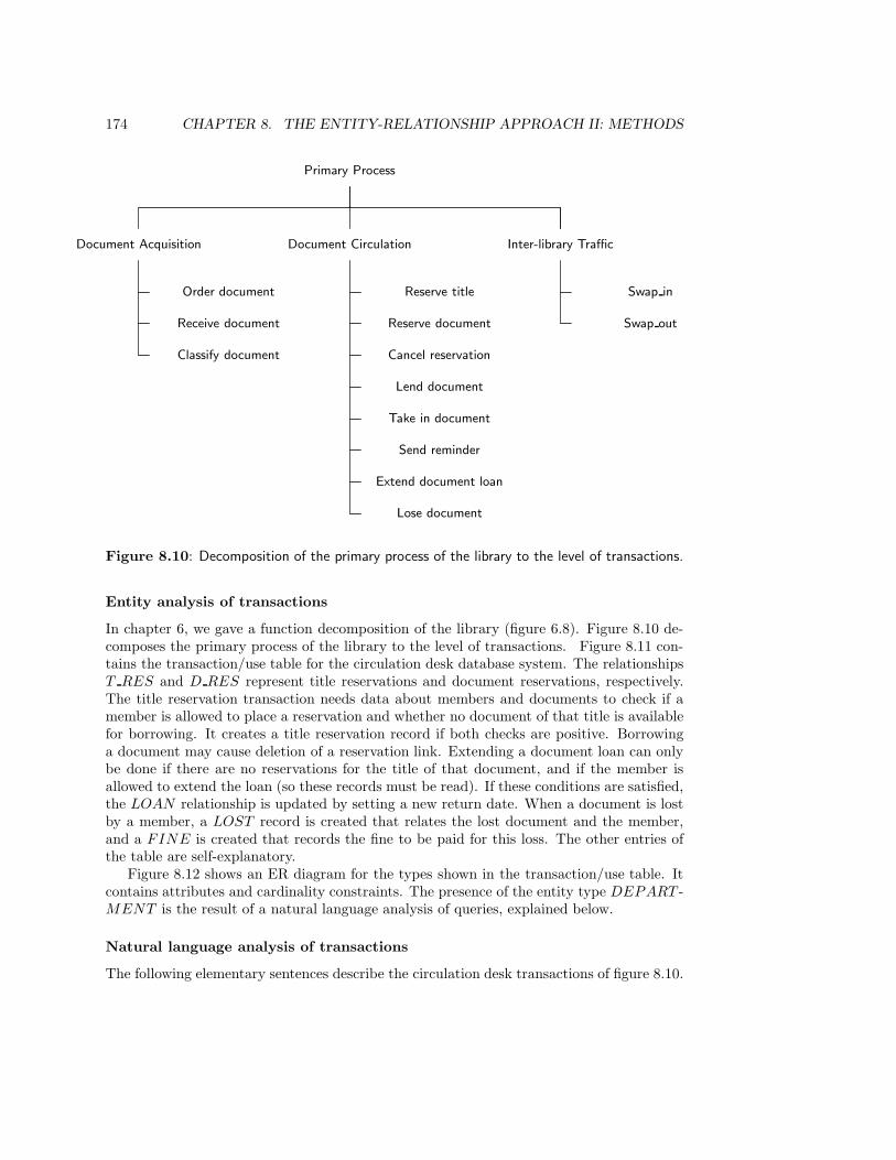
174 CHAPTER 8. THE ENTITY-RELATIONSHIP APPROACH II: METHODS
Primary Process
Document Acquisition Document Circulation Inter-library Traffic
Order document
Receive document
Classify document
Reserve title
Reserve document
Cancel reservation
Lend document
Take in document
Send reminder
Extend document loan
Lose document
Swap in
Swap out
Figure 8.10: Decomposition of the primary process of the library to the level of transactions.
Entity analysis of transactions
In chapter 6, we gave a function decomposition of the library (figure 6.8). Figure 8.10 de-composes the primary process of the library to the level of transactions. Figure 8.11 con-tains the transaction/use table for the circulation desk database system. The relationshipsT RES and D RES represent title reservations and document reservations, respectively.The title reservation transaction needs data about members and documents to check if amember is allowed to place a reservation and whether no document of that title is availablefor borrowing. It creates a title reservation record if both checks are positive. Borrowinga document may cause deletion of a reservation link. Extending a document loan can onlybe done if there are no reservations for the title of that document, and if the member isallowed to extend the loan (so these records must be read). If these conditions are satisfied,the LOAN relationship is updated by setting a new return date. When a document is lostby a member, a LOST record is created that relates the lost document and the member,and a FINE is created that records the fine to be paid for this loss. The other entries ofthe table are self-explanatory.
Figure 8.12 shows an ER diagram for the types shown in the transaction/use table. Itcontains attributes and cardinality constraints. The presence of the entity type DEPART -MENT is the result of a natural language analysis of queries, explained below.
Natural language analysis of transactions
The following elementary sentences describe the circulation desk transactions of figure 8.10.
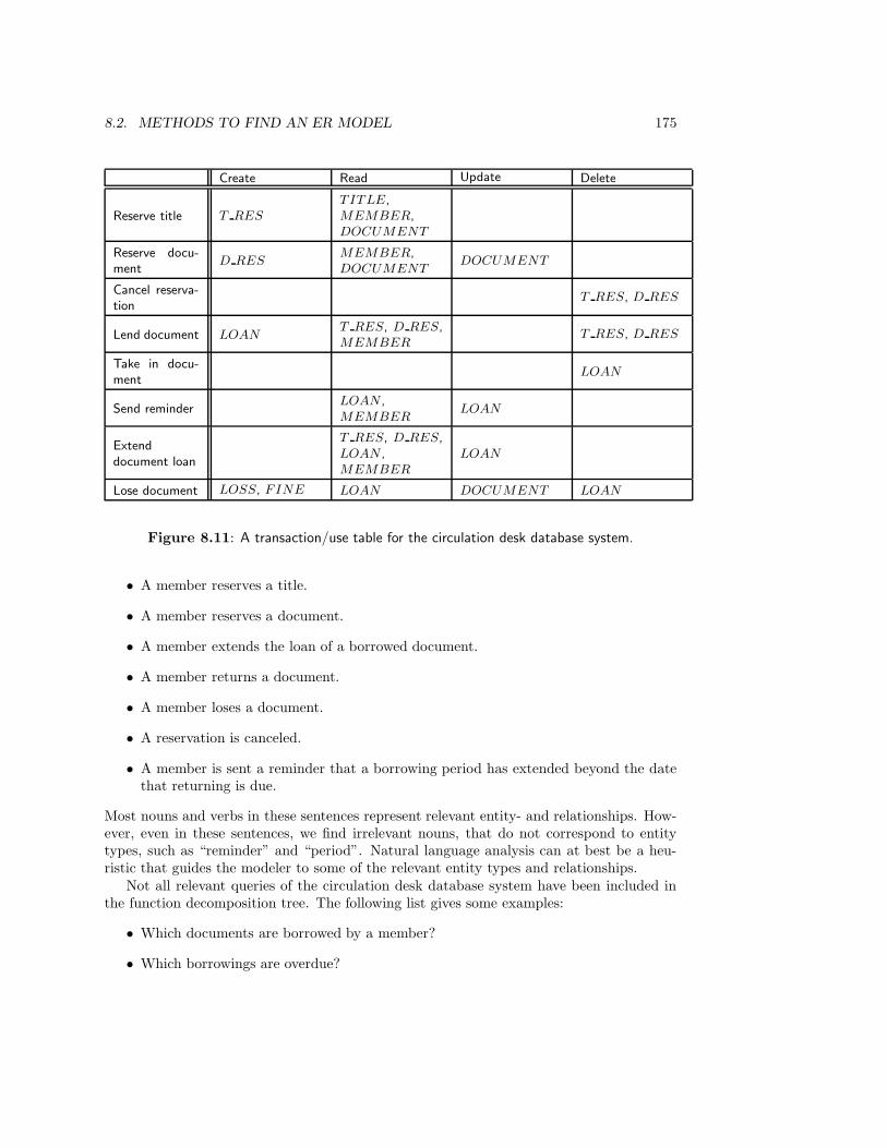
8.2. METHODS TO FIND AN ER MODEL 175
Create Read Update Delete
Reserve title T RES
TITLE,MEMBER,DOCUMENT
Reserve docu-ment
D RESMEMBER,DOCUMENT
DOCUMENT
Cancel reserva-tion
T RES, D RES
Lend document LOANT RES, D RES,MEMBER
T RES, D RES
Take in docu-ment
LOAN
Send reminderLOAN ,MEMBER
LOAN
Extenddocument loan
T RES, D RES,LOAN ,MEMBER
LOAN
Lose document LOSS, FINE LOAN DOCUMENT LOAN
Figure 8.11: A transaction/use table for the circulation desk database system.
• A member reserves a title.
• A member reserves a document.
• A member extends the loan of a borrowed document.
• A member returns a document.
• A member loses a document.
• A reservation is canceled.
• A member is sent a reminder that a borrowing period has extended beyond the datethat returning is due.
Most nouns and verbs in these sentences represent relevant entity- and relationships. How-ever, even in these sentences, we find irrelevant nouns, that do not correspond to entitytypes, such as “reminder” and “period”. Natural language analysis can at best be a heu-ristic that guides the modeler to some of the relevant entity types and relationships.
Not all relevant queries of the circulation desk database system have been included inthe function decomposition tree. The following list gives some examples:
• Which documents are borrowed by a member?
• Which borrowings are overdue?
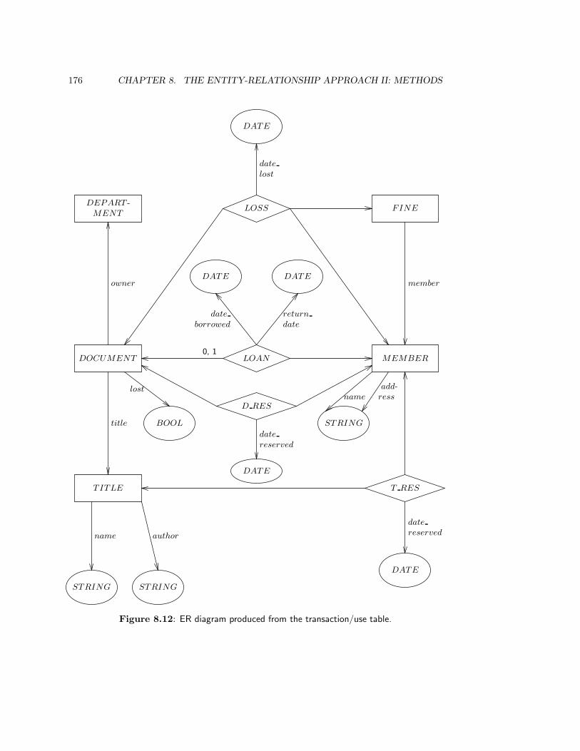
176 CHAPTER 8. THE ENTITY-RELATIONSHIP APPROACH II: METHODS
DOCUMENT LOAN0, 1
MEMBER
DATE DATE
date
borrowed
return
date
FINE
member
LOSS
DATE
date
lost
T ITLE
title
T RES
DATE
date
reserved
D RES
DATE
date
reserved
STRING STRING
name author
DEPART -MENT
owner
BOOL
lost
STRING
add-ressname
Figure 8.12: ER diagram produced from the transaction/use table.
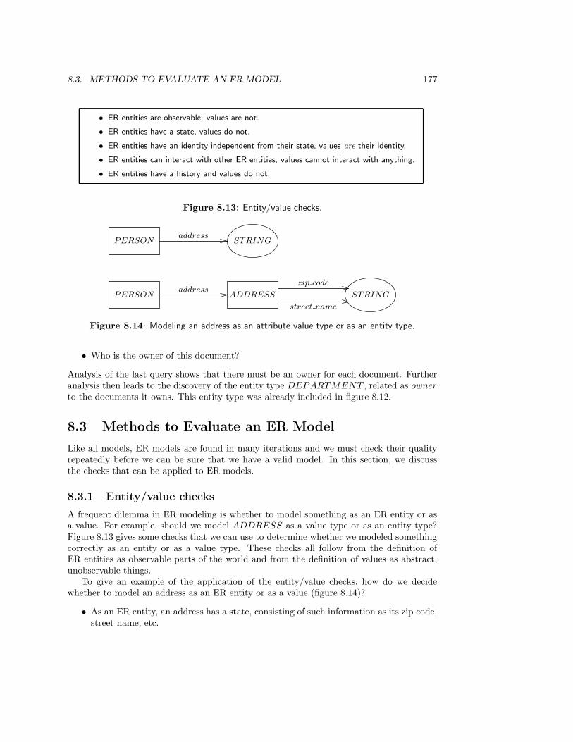
8.3. METHODS TO EVALUATE AN ER MODEL 177
• ER entities are observable, values are not.
• ER entities have a state, values do not.
• ER entities have an identity independent from their state, values are their identity.
• ER entities can interact with other ER entities, values cannot interact with anything.
• ER entities have a history and values do not.
Figure 8.13: Entity/value checks.
PERSON STRINGaddress
PERSON ADDRESSaddress
STRING
zip code
street name
Figure 8.14: Modeling an address as an attribute value type or as an entity type.
• Who is the owner of this document?
Analysis of the last query shows that there must be an owner for each document. Furtheranalysis then leads to the discovery of the entity type DEPARTMENT , related as owner
to the documents it owns. This entity type was already included in figure 8.12.
8.3 Methods to Evaluate an ER Model
Like all models, ER models are found in many iterations and we must check their qualityrepeatedly before we can be sure that we have a valid model. In this section, we discussthe checks that can be applied to ER models.
8.3.1 Entity/value checks
A frequent dilemma in ER modeling is whether to model something as an ER entity or asa value. For example, should we model ADDRESS as a value type or as an entity type?Figure 8.13 gives some checks that we can use to determine whether we modeled somethingcorrectly as an entity or as a value type. These checks all follow from the definition ofER entities as observable parts of the world and from the definition of values as abstract,unobservable things.
To give an example of the application of the entity/value checks, how do we decidewhether to model an address as an ER entity or as a value (figure 8.14)?
• As an ER entity, an address has a state, consisting of such information as its zip code,street name, etc.

178 CHAPTER 8. THE ENTITY-RELATIONSHIP APPROACH II: METHODS
EMPLOY EE MONEYsalary
EMPLOY EE SALARY≥ 1
DATE
MONEY
start
finish
amount
Figure 8.15: Two ways to represent the salary of an employee. In the second representation,salary is an entity type, because it has a history. We can represent the salary the employee hadin different periods of time.
• As a value, an address does not have a state. It could be modeled as a value of typeSTRING, containing a zip code, street name etc. as substrings.
The difference between the two representations is that as an ER entity, one address couldhave had other values for its attributes zip code, street name, etc. If a government were toassign new zip codes to addresses, then this can be modeled without modeling at the sametime that everybody is changing address. It is merely the states of addresses that wouldchange, not the addresses themselves. This would not be possible if address were modeledas a value. Changing the zip code of an address is then strictly not possible: we can onlyreplace one STRING representing an address by another that differs from the first oneonly in its zip code.
Another way to say the same thing is that ER entities have an identity. Saying thatsomething has a state that could have been different, is tantamount to saying that there issomething that remains identical to itself under changes of state. That is, ER entities havean identity that remains invariant under state change.
Taking yet another view on the same difference, ER entities can initiate or suffer events(which may change the state of the entity), but values cannot. This means that ER entitiescan interact with other ER entities. An address modeled as an ER entity will be able toparticipate in an interaction like observe zip code with an observer who reads the zip code,and it can engage in interactions like change zip code and change street name, in whichthe zip code or street name is changed. Since interaction is regarded in this book as thesame thing as observation, we can also say that ER entities can be observed and valuescannot — which is their definition to begin with.
But when ER entities have a state, they potentially have a history. An address modeledas an ER entity can suffer the event change zip code but an address modeled as a STRING
cannot. If we model an address as an ER entity, then we can model its history as the traceof events which occurred in its life. This difference is illustrated in figure 8.15, using asalary attribute as example. In one representation, salary is an attribute that can havedifferent values at different times. The history of these values is not represented. In thesecond representation, salary is an entity type, because it has a history. We can representthe salary the employee had in different periods of time. Note, incidentally, that MONEY
is a value type in both representations.

8.3. METHODS TO EVALUATE AN ER MODEL 179
• The identity of a link is a labeled tuple of the identities of its components. An ERentity is not composed of another identity.
Figure 8.16: Entity/link check.
Relationship Components
LOAN Member, documentWRITE PERMISSION User, filePART OF Car, engineMEMBERSHIP Student, student society
ER entity type “Components”
DEPARTMENT Department membersCAR Engine, wheels, . . .
SCHOOL Faculties
Figure 8.17: Some entity types and relationships.
8.3.2 Entity/link checks
Another dilemma in making an ER model is the decision whether to model something asan ER entity or as a link. Figure 8.16 gives the only difference between ER entities andlinks. The dependent identity check is an immediate consequence of the definition of linksin chapter 7. It is stated in terms of identities instead of identifiers, because the decisionconcerns the entities themselves, not their names. Of course, modeling something as an ERentity or a link has a consequence for the structure of their identifiers. As an example ofthe application of the entity/link check, take the types in figure 8.17. All of the instancesof the types in the table can be viewed as having components in some sense of the word.The difference is that instances of the first four types are identified by means of theircomponents, whereas instances of the last three types are identified independently from theidentity of their components. A document loan is identified by identifying the documentand the member who borrows it, a write permission is identified by identifying the fileand the user who has the permission, etc. We cannot replace the document identifier ina LOAN link by another document identifier without destroying the link and replacing itwith another one. By contrast, a car does not become another car when parts are replaced,a school keeps its identity when faculties are added or deleted, and a department does notbecome another department when members leave it.
Historical relationships
A link is identified by its components. This means that every time the same componentsenter into a relationship, the same link exists. The upper diagram in figure 8.18 shows theLOAN relationship between a member and a document. If the same member borrows thesame document at different times, then the existence set of LOAN contains, at differenttimes, the same instance of LOAN . It is impossible that the existence set of LOAN
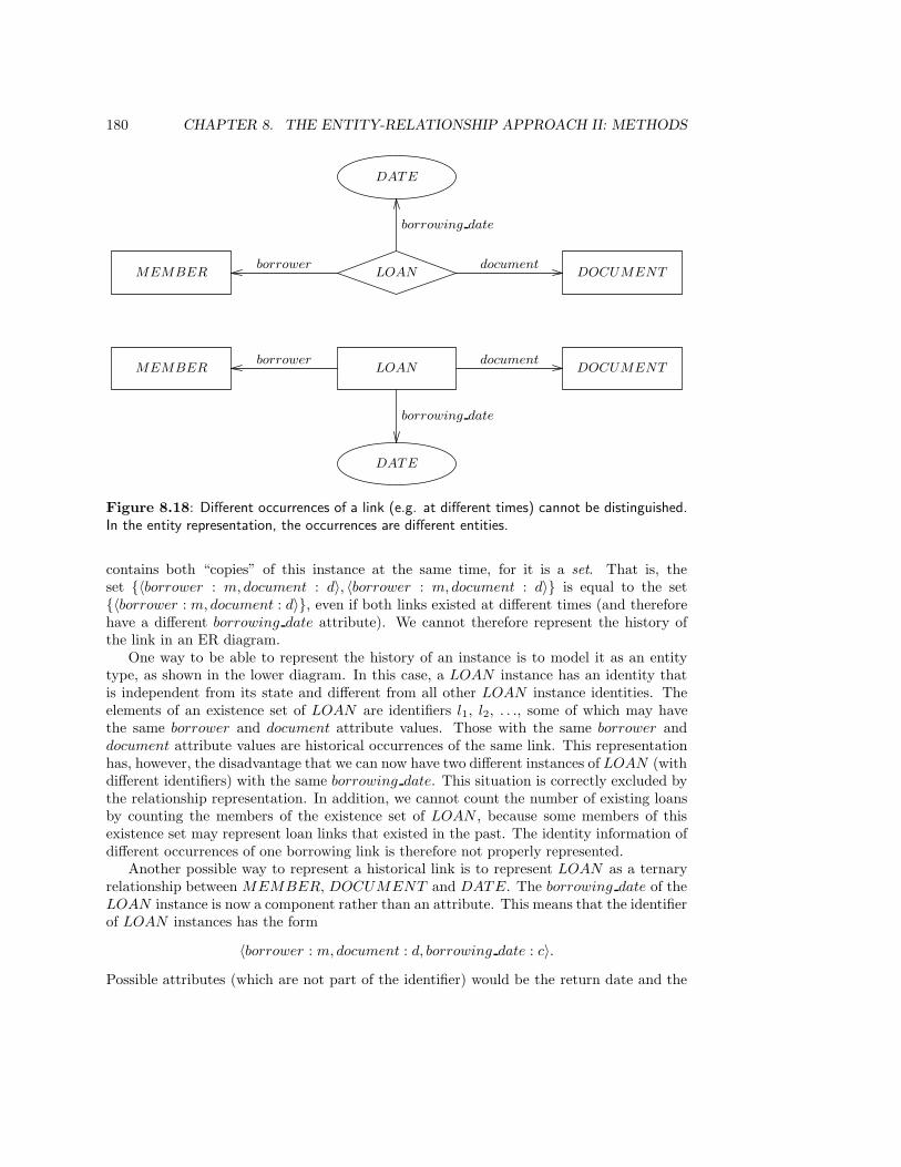
180 CHAPTER 8. THE ENTITY-RELATIONSHIP APPROACH II: METHODS
MEMBER LOANborrower
DOCUMENTdocument
DATE
borrowing date
MEMBER LOAN DOCUMENTborrower document
DATE
borrowing date
Figure 8.18: Different occurrences of a link (e.g. at different times) cannot be distinguished.In the entity representation, the occurrences are different entities.
contains both “copies” of this instance at the same time, for it is a set. That is, theset {〈borrower : m, document : d〉, 〈borrower : m, document : d〉} is equal to the set{〈borrower : m, document : d〉}, even if both links existed at different times (and thereforehave a different borrowing date attribute). We cannot therefore represent the history ofthe link in an ER diagram.
One way to be able to represent the history of an instance is to model it as an entitytype, as shown in the lower diagram. In this case, a LOAN instance has an identity thatis independent from its state and different from all other LOAN instance identities. Theelements of an existence set of LOAN are identifiers l1, l2, . . ., some of which may havethe same borrower and document attribute values. Those with the same borrower anddocument attribute values are historical occurrences of the same link. This representationhas, however, the disadvantage that we can now have two different instances of LOAN (withdifferent identifiers) with the same borrowing date. This situation is correctly excluded bythe relationship representation. In addition, we cannot count the number of existing loansby counting the members of the existence set of LOAN , because some members of thisexistence set may represent loan links that existed in the past. The identity information ofdifferent occurrences of one borrowing link is therefore not properly represented.
Another possible way to represent a historical link is to represent LOAN as a ternaryrelationship between MEMBER, DOCUMENT and DATE. The borrowing date of theLOAN instance is now a component rather than an attribute. This means that the identifierof LOAN instances has the form
〈borrower : m, document : d, borrowing date : c〉.
Possible attributes (which are not part of the identifier) would be the return date and the

8.3. METHODS TO EVALUATE AN ER MODEL 181
EMPLOY EE CHILDparent
NAT NATemp# dependent#
0, 1
Figure 8.19: Example of a “weak” entity type. We will not use weak entity types in this book.
• If T1 is a specialization of T2 then each instance of T1 is identical to an instance of T2.
Figure 8.20: The specialization check.
number of reminders sent. This solution adds a historical dimension to relationships. Itcombines the advantages of the two representations in figure 8.18. We can generalize this byalso adding a historical dimension to entities, so that we can represent different historicalversions of the same (identical) entity.
However, there is no agreed convention to represent historical relationship types in theER approach. Addition of a historical dimension to the Entity-Relationship approach is asubstantial extension to classical Entity-Relationship modeling that would greatly improveits modeling power. We will not treat this extension, as how this can best be done is stilla research issue.
Weak entities
In many texts on the Entity-Relationship approach the concept of a weak entity is used.Roughly speaking, this is an entity that must be identified by a key of another entity con-catenated with some of its own attributes. The archetypical example is shown in figure 8.19.Each employee has key emp# and each employee has zero or more children, who are iden-tified, per employee, by an attribute dependent#. If we want to identify a child in theexistence set of CHILD, we must therefore concatenate the value of emp# with the valueof dependent#.
Each weak entity type always has a “parent type” that must supply part of its identifyinginformation. The relationship from parent type to weak entity type is always a master-detailrelationship. In the days of sequential storage media (magnetic tapes), weak entities wereimplemented as repeating groups within their parent record; this explains the use of a“local key”, that is only unique within the parent record. In a hierarchical data model,weak entities are descendants of their parent entity.
Obviously, the concept of a weak entity has a meaning in the implementation of asoftware system but not in a model of the UoD. Children have their own identity that canbe represented in a UoD model by their own identifier, that does not contain an identifierof any other ER entity. In this book, we will therefore not use weak entity types.
8.3.3 Specialization check
There is only one check to find out whether an is a relationship is correct, and that is to testthe identity statement shown in figure 8.20. By performing this deceptively simple test, weare forced to make explicit what we mean by an is a arrow. For example, is a STUDENT
182 CHAPTER 8. THE ENTITY-RELATIONSHIP APPROACH II: METHODS
a PERSON? The answer seems to be yes, until we realize the consequence of this answer:each STUDENT instance is identical to a PERSON instance. Suppose we want to be ableto represent that one person is a student at two different times in his or her life. Accordingto the national student registration authority in the Netherlands, such a person is twostudents. Since 1 6= 2, this administration cannot represent students as being identicalto persons. As another example, consider the library MEMBER example analyzed insection 7.4. It is clear from that analysis that MEMBER instances are not identical toPERSON instances, and therefore that we have not MEMBER is a PERSON .
8.3.4 Elementary sentence check
One way to validate that an ER model is a correct representation of a UoD is to discuss itwith a domain specialist. However, many domain specialists do not understand the ramifi-cations of an ER diagram, and it is therefore useful to translate the model into elementarysentences and discuss these sentences with the domain specialist. This is called an elemen-tary sentence check. Translation of an ER model into elementary sentences amounts totraveling a road in figure 8.1 in the backwards direction.
Example elementary sentences that correspond to our library model (figure 8.12) are:
• At each moment, each DOCUMENT has an owner.
• At each moment, the owner of each DOCUMENT is a DEPARTMENT .
• At each moment, each DOCUMENT is borrowed by at most one MEMBER.
• At each moment, each MEMBER has a LOAN relationship with zero or moreDOCUMENT s.
The phrase “at each moment” emphasizes that an ER diagram represents what is commonto all states in the state space of the UoD. Any ER diagram can be translated this way into aset of sentences in natural language. Upon reading it, a domain specialist may improve themodel by adding extra information, such as that the owner of a document never changes,or the specialist may correct mistakes, for example by remarking that in the first part oftheir lives, documents have no owner at all.
8.3.5 Population check
A second means to facilitate the understanding of the domain specialist is the populationcheck. This is done by drawing a population diagram of the ER model, which is justa representation of a possible state of the system represented by the diagram. Figure 8.21shows a population diagram of the LOAN relationship. Below each ER entity type andrelationship, a small existence set of that type is drawn in the form of a table. The diagramshows clearly that MEMBER and DOCUMENT instances can exist without being relatedby an existing LOAN instance. Each population diagram should exhibit the cardinalityproperties of the relationship; if some cardinalities are not possible in the UoD, then thedomain specialist can discover these omitted cardinality properties by means of a populationdiagram that violates them.

8.3. METHODS TO EVALUATE AN ER MODEL 183
MEMBER LOAN DOCUMENT
STRING NAT
name pass#
DATE
return date
NAT
code
0, 1
c1
c2
c3
c4
d1
d2
d3
d4
d5
〈c1, d3, return date : 920929〉
〈c1, d5, return date : 920929〉
〈c4, d1, return date : 921005〉
Figure 8.21: A population diagram.
STUDENT CLUBmember of
UNIV ERSITY
affiliationregistered at
Figure 8.22: If the equation registered at(s) = affiliation(member of(s)) is always true,then registered at is a redundant relationship.
8.3.6 Derivable relationship check
In the derivable relationship check, we check whether there are relationships that canbe derived from other relationships. A simple case of this where all involved relationshipsare functional is illustrated in figure 8.22. If in every possible state of the modeled part ofthe world, for every existing student s we have
registered at(s) = affiliation(member of(s)),
then the registered at relationship is redundant.It is a choice of the modeler whether or not to remove a derivable relationship from
the model. One reason why we should remove it is that this would make the model moreunderstandable. A second reason why we should remove it is that the specification of statechanges is more complex if we include a derived relationship. If either of the relationshipsregistered at or member of changes, then affiliation should be specified to change aswell. This may lead to an update anomaly if one of these relationships is updated butaffiliation remains unchanged.
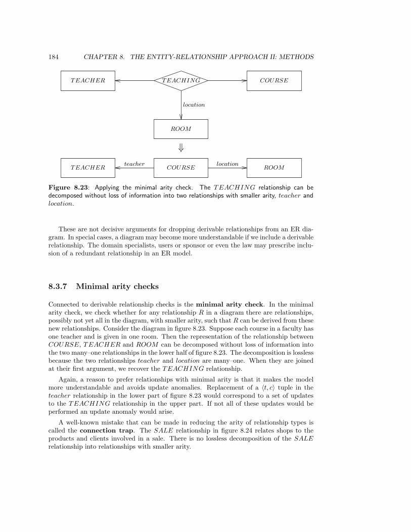
184 CHAPTER 8. THE ENTITY-RELATIONSHIP APPROACH II: METHODS
TEACHER COURSE
ROOM
TEACHING
location
TEACHER COURSEteacher
ROOMlocation
⇓
Figure 8.23: Applying the minimal arity check. The TEACHING relationship can bedecomposed without loss of information into two relationships with smaller arity, teacher andlocation.
These are not decisive arguments for dropping derivable relationships from an ER dia-gram. In special cases, a diagram may become more understandable if we include a derivablerelationship. The domain specialists, users or sponsor or even the law may prescribe inclu-sion of a redundant relationship in an ER model.
8.3.7 Minimal arity checks
Connected to derivable relationship checks is the minimal arity check. In the minimalarity check, we check whether for any relationship R in a diagram there are relationships,possibly not yet all in the diagram, with smaller arity, such that R can be derived from thesenew relationships. Consider the diagram in figure 8.23. Suppose each course in a faculty hasone teacher and is given in one room. Then the representation of the relationship betweenCOURSE, TEACHER and ROOM can be decomposed without loss of information intothe two many–one relationships in the lower half of figure 8.23. The decomposition is losslessbecause the two relationships teacher and location are many–one. When they are joinedat their first argument, we recover the TEACHING relationship.
Again, a reason to prefer relationships with minimal arity is that it makes the modelmore understandable and avoids update anomalies. Replacement of a 〈t, c〉 tuple in theteacher relationship in the lower part of figure 8.23 would correspond to a set of updatesto the TEACHING relationship in the upper part. If not all of these updates would beperformed an update anomaly would arise.
A well-known mistake that can be made in reducing the arity of relationship types iscalled the connection trap. The SALE relationship in figure 8.24 relates shops to theproducts and clients involved in a sale. There is no lossless decomposition of the SALE
relationship into relationships with smaller arity.

8.3. METHODS TO EVALUATE AN ER MODEL 185
SHOP SALE CLIENT
PRODUCT
Figure 8.24: The connection trap. The SALE relationship cannot be decomposed intorelationships with smaller arity without loss of information.
8.3.8 Creation/deletion check
The creation/deletion check can be used to check the completeness of our ER model. We usethe transaction decomposition table shown in figure 8.8 to check whether for every entitytype or relationship in it, there are transactions that create or delete it. If there is no C orno D in a row of the table, we must either explain this absence or repair this omission tothe model. For example, in the COURSE row of table 8.8, there is no C or D transactionbecause course administration has not been modeled. We should add these transactions ina more complete ER model of the UoD.
It is not always necessary that every entity or relationship be created or deleted. Forexample, in a model of an elevator system, relevant entity types are BUTTON , FLOOR,etc. The existence sets of these entity types are fixed during the useful life of the system.Even if they are not fixed, e.g. because the building is renovated and new floors are added,then the creation of new FLOOR instances is not done in a transaction with a user of theelevator system.
8.3.9 Cross-checking
One way to check the mutual consistency of different parts of the model is to perform cross-checking. Cross-checking consists in traveling in different directions through the map ofinduction methods shown in figure 8.1, and checking if we get mutually consistent results.For example, we can perform natural language analysis starting from a piece of text and,independently, do an entity analysis of transactions starting from a function decompositiontree. The resulting models are likely not to be identical, and we can improve the quality ofboth by merging them in the way described in the section on view integration below. Theresult should be consistent with the natural language analysis as well as with the transactionanalysis.
Similarly, we can independently perform an entity analysis of transactions starting froma natural language analysis of transactions, and check whether the results are the same.For example, in a natural language analysis of transactions of the student administrationsystem, we should have found the following elementary sentence for the transaction ListCourse Participants:
• List students who are enrolled in a course.
This elementary sentence is consistent with the description of the transaction in figure 8.7.
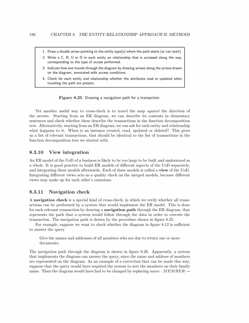
186 CHAPTER 8. THE ENTITY-RELATIONSHIP APPROACH II: METHODS
1. Draw a double arrow pointing to the entity type(s) where the path starts (or can start).
2. Write a C, R, U or D in each entity an relationship that is accessed along the way,corresponding to the type of access performed.
3. Indicate how one travels through the diagram by drawing arrows along the arrows drawnon the diagram, annotated with access conditions.
4. Check for each entity and relationship whether the attributes read or updated whentraveling the path are present.
Figure 8.25: Drawing a navigation path for a transaction.
Yet another useful way to cross-check is to travel the map against the direction ofthe arrows. Starting from an ER diagram, we can describe its contents in elementarysentences and check whether these describe the transactions in the function decompositiontree. Alternatively, starting from an ER diagram, we can ask for each entity and relationshipwhat happens to it. When is an instance created, read, updated or deleted? This givesus a list of relevant transactions, that should be identical to the list of transactions in thefunction decomposition tree we started with.
8.3.10 View integration
An ER model of the UoD of a business is likely to be too large to be built and understood asa whole. It is good practice to build ER models of different aspects of the UoD separately,and integrating these models afterwards. Each of these models is called a view of the UoD.Integrating different views acts as a quality check on the merged models, because differentviews may make up for each other’s omissions.
8.3.11 Navigation check
A navigation check is a special kind of cross-check, in which we verify whether all trans-actions can be performed by a system that would implement the ER model. This is donefor each relevant transaction by drawing a navigation path through the ER diagram, thatrepresents the path that a system would follow through the data in order to execute thetransaction. The navigation path is drawn by the procedure shown in figure 8.25.
For example, suppose we want to check whether the diagram in figure 8.12 is sufficientto answer the query
Give the names and addresses of all members who are due to return one or moredocuments.
The navigation path through the diagram is shown in figure 8.26. Apparently, a systemthat implements the diagram can answer the query, since the name and address of membersare represented on the diagram. As an example of a correction that can be made this way,suppose that the query would have required the system to sort the members on their familyname. Then the diagram would have had to be changed by replacing name : MEMBER →
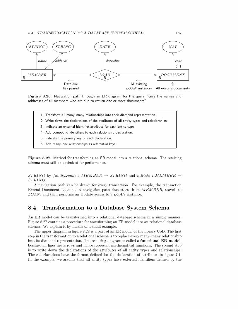
8.4. TRANSFORMATION TO A DATABASE SYSTEM SCHEMA 187
MEMBERR
LOANR
DOCUMENTR
STRING STRING
name address
DATE
date due
NAT
code
0, 1
⇑All existing documents
⇐=Date duehas passed
⇐=All existing
LOAN instances
Figure 8.26: Navigation path through an ER diagram for the query “Give the names andaddresses of all members who are due to return one or more documents”.
1. Transform all many–many relationships into their diamond representation.
2. Write down the declarations of the attributes of all entity types and relationships.
3. Indicate an external identifier attribute for each entity type.
4. Add compound identifiers to each relationship declaration.
5. Indicate the primary key of each declaration.
6. Add many–one relationships as referential keys.
Figure 8.27: Method for transforming an ER model into a relational schema. The resultingschema must still be optimized for performance.
STRING by family name : MEMBER → STRING and initials : MEMBER →STRING.
A navigation path can be drawn for every transaction. For example, the transactionExtend Document Loan has a navigation path that starts from MEMBER, travels toLOAN , and then performs an Update access to a LOAN instance.
8.4 Transformation to a Database System Schema
An ER model can be transformed into a relational database schema in a simple manner.Figure 8.27 contains a procedure for transforming an ER model into an relational databaseschema. We explain it by means of a small example.
The upper diagram in figure 8.28 is a part of an ER model of the library UoD. The firststep in the transformation to a relational schema is to replace every many–many relationshipinto its diamond representation. The resulting diagram is called a functional ER model,because all lines are arrows and hence represent mathematical functions. The second stepis to write down the declarations of the attributes of all entity types and relationships.These declarations have the format defined for the declaration of attributes in figure 7.1.In the example, we assume that all entity types have external identifiers defined by the
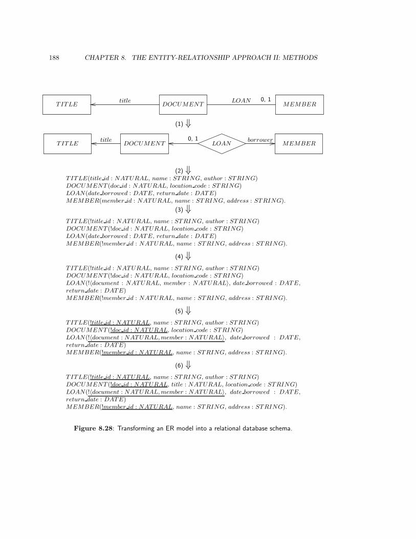
188 CHAPTER 8. THE ENTITY-RELATIONSHIP APPROACH II: METHODS
TITLE DOCUMENTtitle
MEMBERLOAN 0, 1
TITLE DOCUMENT MEMBERLOAN0, 1 borrowertitle
(1) ⇓
(2) ⇓TITLE(title id : NATURAL, name : STRING, author : STRING)DOCUMENT (doc id : NATURAL, location code : STRING)LOAN(date borrowed : DATE, return date : DATE)MEMBER(member id : NATURAL, name : STRING, address : STRING).
(3) ⇓TITLE(!title id : NATURAL, name : STRING, author : STRING)DOCUMENT (!doc id : NATURAL, location code : STRING)LOAN(date borrowed : DATE, return date : DATE)MEMBER(!member id : NATURAL, name : STRING, address : STRING).
(4) ⇓TITLE(!title id : NATURAL, name : STRING, author : STRING)DOCUMENT (!doc id : NATURAL, location code : STRING)LOAN(!〈document : NATURAL, member : NATURAL〉, date borrowed : DATE,
return date : DATE)MEMBER(!member id : NATURAL, name : STRING, address : STRING).
(5) ⇓TITLE(!title id : NATURAL, name : STRING, author : STRING)DOCUMENT (!doc id : NATURAL, location code : STRING)LOAN(!〈document : NATURAL, member : NATURAL〉, date borrowed : DATE,
return date : DATE)MEMBER(!member id : NATURAL, name : STRING, address : STRING).
(6) ⇓TITLE(!title id : NATURAL, name : STRING, author : STRING)DOCUMENT (!doc id : NATURAL, title : NATURAL, location code : STRING)LOAN(!〈document : NATURAL, member : NATURAL〉, date borrowed : DATE,
return date : DATE)MEMBER(!member id : NATURAL, name : STRING, address : STRING).
Figure 8.28: Transforming an ER model into a relational database schema.

8.5. METHODOLOGICAL ANALYSIS 189
library and visible to library employees; these identifiers are indicated in the third step byexclamation marks. Addition of identifier attributes requires some care. As indicated bythe discussion in section 7.4, we may have to consult library regulations to find out howentities are identified. If there are entity types without external identifiers, we must consultthe sponsor and customer to decide how to add these identifiers. If identification is notimportant for some entity types, we should add internal identifiers, which are generated bythe system and which are invisible to the user of the system.
Having provided a mechanism to identify entities, we can in the fourth step add com-pound relationship identifiers. The components of the relationship identifier are the iden-tifiers of the component entity types. Note that document is really a function LOAN →DOCUMENT , but that in the attribute declarations, we replace DOCUMENT withNATURAL. We can do this because in the function composition
LOANdocument
−−−−−→ DOCUMENTdoc id
−−−→ NATURAL
the function doc id is one-one. By replacing DOCUMENT with NATURAL, we prepareourselves for the translation into types available in DBMS schema languages.
In step five, we add the relational concept of a key. A key is a combination of attributevalues whose value is unique in each existence set. The simplest thing to do is to define eachexternal identifier to be a key. If an entity type does not have an external identifier, thenwe must consult domain specialists to determine which combinations of attribute values isunique in each existence set. A relationship may now get a compound key in which onecomponent is a compound key of an entity type.
Finally, in step six we add many–one relationships as referential keys to entity types.The resulting declarations have the form of relation schemas. Translation of these schemasinto a database schema definition language such as SQL requires one more decision, viz.the translation of the value types into the data types available in the schema definitionlanguage. There are algorithms to support the transformation of an ER diagram into arelational database schema, which perform optimizations in special cases.
8.5 Methodological Analysis
8.5.1 The place of the ER method in the development framework
System hierarchy. The ER modeling notation has been developed to represent the UoDof database systems. However, it can be used to represent the UoD of any data manipulationsystem, including the UoD of organizations, of computer-based systems and of softwaresystems. This has already been indicated in figure 3.15.
We remarked in section 6.6 that the decomposition of the business into computer-basedsystems and of these into software systems is independent from a decomposition of theUoD into subsystems. For any particular UoD, we can define an aggregation hierarchy; butsince we make no assumptions about the kind of UoD we are modeling, we do not assumeany particular hierarchy in the UoD. As a consequence, we cannot allocate ER modelingto any level in the aggregation hierarchy of our development framework, for this hierarchydecomposes a business into computer-based systems, these into software systems etc.
Moreover, because the UoD of a business may also be the UoD of a software system, anER model of the UoD of a business can be used as an ER model of the UoD of a software
190 CHAPTER 8. THE ENTITY-RELATIONSHIP APPROACH II: METHODS
system. We saw this already in chapter 6: Moving from ISP to business area analysis,we may add cardinality constraints, but the subject areas and entity types relevant in abusiness area are also subject areas and entity types relevant for the entire business.
The transformation of an ER model into a relational database schema brings us intothe realm of software subsystems. In the system hierarchy, this is a decomposition. Inthe example of figure 8.28, the relation schemas correspond one–one with entity types andrelationships, so there does not seem to be much of a decomposition in this move. However,there is a decomposition of focus: in the ER model, the atoms of the model are entity typesand their relationships; in the relational schemas, the atoms of the model are attributes.Furthermore, optimization of the schemas may lead to splitting of relation schemas on thebasis of access patterns.
8.5.2 Modeling and engineering
As spelled out in section 7.8, an ER model can represent the state space of a computer-based system (or a business or a software system) as well as of the UoD of that system. Themeaning of statements made by the model may be quite different in these two interpreta-tions. A cardinality statement that expresses a regularity about the UoD is a norm wheninterpreted as a statement about the system, and a cardinality statement that expresses anorm for the UoD may or may not be interpreted as a norm for the system. This has anobvious methodological consequence for model validation. If there is a mismatch betweenan ER model and the UoD, then the model is wrong; but if there is a mismatch betweenthe model and the system, then the system is wrong.
This is a consequence of the fact that when modeling the UoD, we should follow theempirical cycle of discovery, but when specifying a system, we should follow the engineeringcycle. As explained in chapter 3, in both cycles we follow a rational problem solvingprocess in which we generate alternative solutions, estimate likely effects, evaluate theseand then make a choice. In the empirical cycle of modeling a UoD, we estimate effects of amodel by deducing observable consequences, and evaluate these by performing experiments.The population check and the elementary sentence checks are (very simple) ways to deduceconsequences of an ER model and test these. Most other evaluation heuristics of ER modelsare quality checks in which we verify the use we made of the modeling constructs.
Once we have an ER model of the UoD, we can turn around and view it as a model of thestate space of a computer-based system. Entities and links in the system are then surrogatesfor entities and links in the UoD, and cardinality regularities in the UoD model now becomecardinality constraints on the system. Viewed as a model of the system, we can now adda specification of how many instances of a certain type we want the system to be able tohandle, even if this constraint does not correspond to a regularity in the UoD. We may alsodecide to enforce some constraints on the UoD by implementing them as constraints onthe system. The UoD constraint that a member must not borrow more than 20 documentssimultaneously may be translated into a system constraint, but the UoD constraint that amember must return a document within three weeks will not be translated into a systemconstraint. As a consequence of these decisions, a system that represents one member tohave borrowed 21 documents simultaneously is wrong (it violates a system constraint), buta system that represents one member to have borrowed a document for four weeks may beright (when it represents a UoD entity that violates a UoD constraint).
Estimation of the likely effects of the ER model involves thinking through likely usage
8.5. METHODOLOGICAL ANALYSIS 191
scenarios in order to check whether the constraints imposed on the system allow effectiveand efficient handling of these scenarios. The navigation check is an evaluation of thecapability of the SuD to perform some of its functions, viz. to answer certain queries.
Thus, during ER modeling we start with empirical modeling of the UoD and end withengineering a system. In the process, our interpretation of statements changes from regular-ities to constraints, and our interpretation of model evaluations changes from a descriptivemode in UoD modeling to an prescriptive mode in system engineering.
8.5.3 Natural language analysis in NIAM
Natural language analysis plays an important role in NIAM, a method for modeling theworld as fact types and value types [244]. Fact types are similar to relationships, exceptthat fact types can relate entity as well as value types. An attribute is modeled in NIAM asa binary fact type that relates an entity type and a value type. NIAM has also been calledthe binary relationship method, because in its earlier versions, it only accepted binaryfact types. In more recent versions, NIAM also accepts n-ary fact types.
Fact types in NIAM correspond directly to elementary sentences. Fact types can befound using Nijssen’s telephone heuristic: Imagine that you are phoning someone whohas a grasp of elementary English and has no knowledge of the UoD you are trying to model,and that you try to describe the current state of the UoD to that person. The sentencesthat you then use describe a model of that state. The sentences describe particulars, suchas
“The member with member number 123 has borrowed document with key ABC”
This statement about an individual state of affairs can easily be transformed into a hypoth-esis about all possible states of the UoD, such as
• There is a class of possible objects called MEMBER.
• MEMBER instances are identified by their member number.
• There is a class of possible objects called DOCUMENT .
• DOCUMENT instances are identified by a key.
• MEMBER instances can borrow DOCUMENT instances.
These elementary sentences can be translated directly into NIAM fact types, but they canalso be translated into ER entity types, relationships and constraints on these.
The difference between NIAM natural language analysis and ER natural language anal-ysis is that NIAM starts at the instance level and ER modeling starts at the type level. Theexample elementary sentence above describes a particular fact in which particular entitiesand links are described. The example elementary sentences in subsection 8.2.1 describetypes of facts and do not refer to particulars. This difference is not essential and we canuse either type of sentence in an ER or NIAM natural language analysis.
192 CHAPTER 8. THE ENTITY-RELATIONSHIP APPROACH II: METHODS
8.6 Summary
Two methods for discovering ER models from a set of observation data were treated: naturallanguage analysis and entity analysis of transactions. Natural language analysis starts fromelementary sentences describing the UoD and translates these sentences into ER diagrams.This may yield many irrelevant entity types and relationships. To focus on relevant entitytypes and relationships, we can start with the required system transactions, including thequeries that the system must be able to answer, and describe these in elementary sentences.Because the required transactions manipulate data that has a meaning in the UoD, thesesentences are elementary descriptions of the UoD. Natural language analysis of transactionsresults in an ER model of the UoD. Query analysis is a special case of this.
A different method is entity analysis of transactions, in which we, for each requiredtransaction, ask what data are created, read, updated or deleted. These data have a meaningin the UoD, and if we make an ER model of them, we have a model of the UoD.
Several groups of methods were discussed to evaluate ER models. Entities have an iden-tity and a state, values have no state (entity/value check). Entities have a simple identity,links have a compound identity (entity/link check). Each specialization instance is identi-cal to a generalization instance (is a check). Absent creation or deletion transactions foran entity type or relationship may indicate an incomplete model (creation/deletion check).Another way to check the completeness of the model is by means of cross-checking and viewintegration. The model is simplified if we take care that all relationships are minimal (mini-mal arity check) and if we remove derivable relationships (derivable relationship check). Bymeans of the elementary sentence check and population check, we can validate the truthvalue of the model with domain specialists. This is a simple way to do empirical tests ofthe model. The navigation check can tell us whether the system will be able to perform therequired functions.
Transformation of an ER model into a relational database schema brings us to the levelof software subsystems. This represents a decomposition of entity types and relationshipsinto attributes. Performance considerations can cause us to factor out groups of attributesinto separate relation schemas.
ER models can be used to model the UoD of a business, of a computer-based systemor of a software system. All these systems may have the same UoD, because the UoD isnot part of the aggregation hierarchy of computer-based systems. Each UoD has its ownaggregation hierarchy, about which we make no assumptions in this book. ER models canbe used to represent the state space of the UoD or of a system under development. As aUoD model, it has a descriptive orientation and the empirical cycle of discovery must befollowed. As a system specification, it has a prescriptive orientation and the engineeringcycle of product development must be followed.
8.7 Exercises
1. One of the following constraints can be expressed as a cardinality constraint in fig-ure 8.24, the other cannot. Add the representable one to the diagram.
• Each client buys at least one part at a shop.
• Each client buys at most two parts in one shop.
8.8. BIBLIOGRAPHICAL REMARKS 193
2. Discuss the consequences of modeling AUTHOR and PUBLISHER as a value typeand modeling them as an entity type. What would you choose in a model of thecirculation desk UoD?
3. Discuss the consequences of modeling DELIV ERY in figure 7.7 as a relationship andas an entity type.
4. Which of the following relationships are is a relationships?
• This is a car.
• A Ford is a car.
• Ford is a type of car.
• A teacher is a member of staff.
5. Change the ER model in figure 8.9 in such a way that the result attributes ofPRACTICAL and TEST REG do not need to have a null value in their codomain.
6. Add a type/instance distinction to PRACTICAL, TEST and COURSE. For ex-ample, there is a course “Conceptual Modeling” (a type) that is given every autumn(an instance).
7. In exercise 7 of chapter 7, you were asked to draw a relationship type that has anotherrelationship as a component. What does this mean for the transformation of an ERmodel into a relational schema?
8.8 Bibliographical Remarks
ER methods. ER modeling methods are presented by Teory, Yang and Fry [339], andby Batini, Ceri and Navathe [25]. Another source used for this chapter is Storey [327]. Adetailed and practical introduction to ER modeling is given by Rock-Evans [280, 281]. Anabbreviated version is given in a later work [284].
Natural language analysis. Natural language analysis was proposed in 1983 by Chen [66].It is used in several proposals for modeling, such as a method proposed by Abbott [1] towrite ADA programs and a method proposed by Saeki, Horai and Enomoto [299] to performsoftware development. Natural language analysis at the instance level plays a central rolein NIAM [244].
Transactions analysis. The method of entity analysis of transactions presented in thischapter is based upon a proposal by Flavin [105]. A thorough description of transactionanalysis is given by Rock-Evans [280, 281, 282, 283]. An accessible summary of thesemethods is given in a later work [284].

194 CHAPTER 8. THE ENTITY-RELATIONSHIP APPROACH II: METHODS
Evaluation methods. Some of the evaluation methods have been taken from existingliterature on ER methods, such as Batini et al. [25], Teory et al. [339], and Storey [327].The definition of ER concepts in chapter 7 is used in the entity/value and entity/linkchecks. The creation/deletion checks are taken from Information Engineering. The use ofnavigation paths to perform the query check is well-known in ER modeling and is describedby, for example, Batini et al. [25]. The population check is taken from NIAM [244]. Theminimal arity check is based on a step known in NIAM as the arity check. View integrationtechniques and methods are described in Batini and Lenzerini [26] and Navathe, Elmasriand Larson [242]. A survey of view integration methods is given by Batini, Lenzerini andNavathe [27].
Transformation to database system schema. Many papers and books that proposeER methods have something to say about transformation of an ER diagram into a relationaldatabase system schema. Useful introductions and surveys are given by Batini et al. [25],Storey [327], Teory [338], and Teory, Yang and Fry [339].
Chapter 9
Structured Analysis I: Models
9.1 Introduction
Structured analysis is a method to specify the observable behavior of a software system ina way that reflects the essential tasks to be performed by the software system. In a rationaldevelopment process, structured analysis would be followed by structured design to developa modular architecture of software systems, and by structured programming. The historicalsequence in which these methods were proposed is the reverse of this: structured program-ming was proposed around 1970 and structured design and analysis were proposed in thelate 1970s. The move from structured programming to structured analysis parallels themove from relational databases to entity-relationship modeling, because both movementsturn away from implementation structures towards problem structures.
In this chapter, we treat the notation system used by structured analysis, the data flownotation. The notation is general enough to be used for systems that manipulate materialand energy as well but in this chapter, we restrict ourselves to the representation of datamanipulation. Extension of the notation to deal with material and energy manipulation isleft as an exercise for the reader.
Sections 9.2 and 9.3 survey the structure of data flow models: a data flow model rep-resents a system that receives data flows from the environment, transforms the receiveddata, stores them and sends data flows as response to the environment (section 9.2). Theenvironment with which the system communicates is represented by external entities andby time (section 9.3). Section 9.4 looks at data stores and the way in which we can usean ER diagram to represent the structure of data stores. Section 9.5 looks at data flowsand section 9.6 discusses the specification and decomposition of data transformations. Insection 9.7, data flow models are analyzed from a methodological point of view.
9.2 Components of a Data Flow Model
Data flow models can be used to represent any kind of data manipulation system, rangingfrom (the data manipulation aspect of) businesses to computer-based systems and softwaresystems. Just like an ISAC activity model, a data flow model represents a data manipulationsystem by specifying the data manipulation activities performed by the system and the data
195
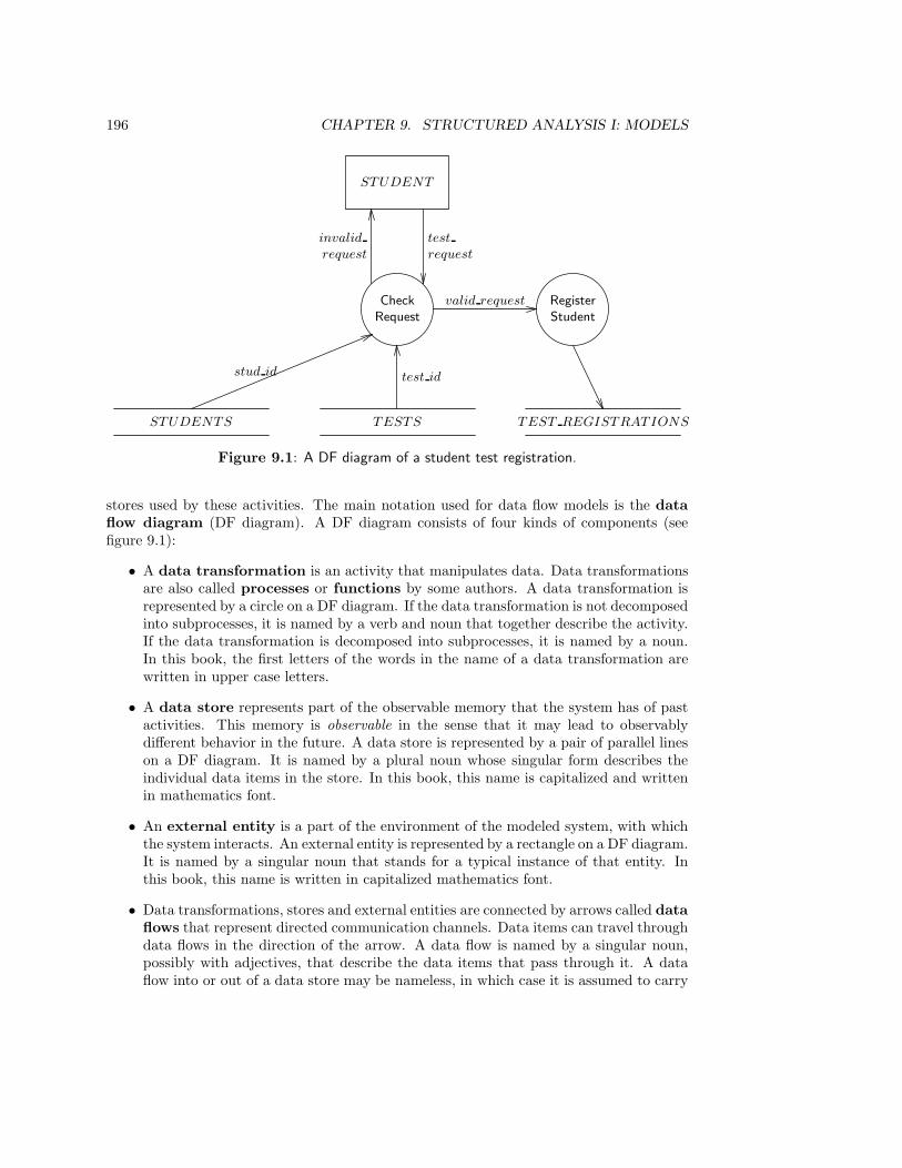
196 CHAPTER 9. STRUCTURED ANALYSIS I: MODELS
CheckRequest
STUDENT
RegisterStudent
valid request
test
request
invalid
request
TESTS
test id
STUDENTS
stud id
TEST REGISTRATIONS
Figure 9.1: A DF diagram of a student test registration.
stores used by these activities. The main notation used for data flow models is the dataflow diagram (DF diagram). A DF diagram consists of four kinds of components (seefigure 9.1):
• A data transformation is an activity that manipulates data. Data transformationsare also called processes or functions by some authors. A data transformation isrepresented by a circle on a DF diagram. If the data transformation is not decomposedinto subprocesses, it is named by a verb and noun that together describe the activity.If the data transformation is decomposed into subprocesses, it is named by a noun.In this book, the first letters of the words in the name of a data transformation arewritten in upper case letters.
• A data store represents part of the observable memory that the system has of pastactivities. This memory is observable in the sense that it may lead to observablydifferent behavior in the future. A data store is represented by a pair of parallel lineson a DF diagram. It is named by a plural noun whose singular form describes theindividual data items in the store. In this book, this name is capitalized and writtenin mathematics font.
• An external entity is a part of the environment of the modeled system, with whichthe system interacts. An external entity is represented by a rectangle on a DF diagram.It is named by a singular noun that stands for a typical instance of that entity. Inthis book, this name is written in capitalized mathematics font.
• Data transformations, stores and external entities are connected by arrows called dataflows that represent directed communication channels. Data items can travel throughdata flows in the direction of the arrow. A data flow is named by a singular noun,possibly with adjectives, that describe the data items that pass through it. A dataflow into or out of a data store may be nameless, in which case it is assumed to carry
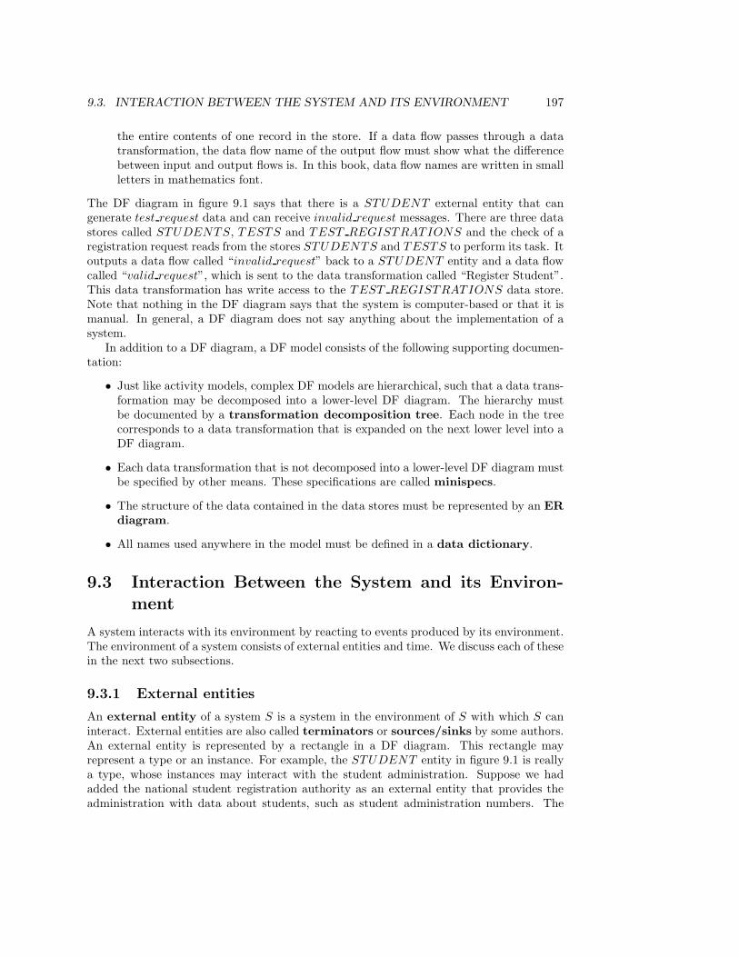
9.3. INTERACTION BETWEEN THE SYSTEM AND ITS ENVIRONMENT 197
the entire contents of one record in the store. If a data flow passes through a datatransformation, the data flow name of the output flow must show what the differencebetween input and output flows is. In this book, data flow names are written in smallletters in mathematics font.
The DF diagram in figure 9.1 says that there is a STUDENT external entity that cangenerate test request data and can receive invalid request messages. There are three datastores called STUDENTS, TESTS and TEST REGISTRATIONS and the check of aregistration request reads from the stores STUDENTS and TESTS to perform its task. Itoutputs a data flow called “invalid request” back to a STUDENT entity and a data flowcalled “valid request”, which is sent to the data transformation called “Register Student”.This data transformation has write access to the TEST REGISTRATIONS data store.Note that nothing in the DF diagram says that the system is computer-based or that it ismanual. In general, a DF diagram does not say anything about the implementation of asystem.
In addition to a DF diagram, a DF model consists of the following supporting documen-tation:
• Just like activity models, complex DF models are hierarchical, such that a data trans-formation may be decomposed into a lower-level DF diagram. The hierarchy mustbe documented by a transformation decomposition tree. Each node in the treecorresponds to a data transformation that is expanded on the next lower level into aDF diagram.
• Each data transformation that is not decomposed into a lower-level DF diagram mustbe specified by other means. These specifications are called minispecs.
• The structure of the data contained in the data stores must be represented by an ERdiagram.
• All names used anywhere in the model must be defined in a data dictionary.
9.3 Interaction Between the System and its Environ-ment
A system interacts with its environment by reacting to events produced by its environment.The environment of a system consists of external entities and time. We discuss each of thesein the next two subsections.
9.3.1 External entities
An external entity of a system S is a system in the environment of S with which S caninteract. External entities are also called terminators or sources/sinks by some authors.An external entity is represented by a rectangle in a DF diagram. This rectangle mayrepresent a type or an instance. For example, the STUDENT entity in figure 9.1 is reallya type, whose instances may interact with the student administration. Suppose we hadadded the national student registration authority as an external entity that provides theadministration with data about students, such as student administration numbers. The

198 CHAPTER 9. STRUCTURED ANALYSIS I: MODELS
rectangle for the national student registration authority would then represent an instancerather than a type.
When the environment does something to which the system must respond, an event issaid to occur. Events must be discrete in time. The continuous change of temperature in aroom is not an event, reaching a specified temperature to which the system must respond(e.g. by shutting off a heater) is an event. The response of a system to an event isthe observable activity of the system caused by the event. More in particular, the systemresponse consists of any observable output produced by the system as well as any changein the data stores that may lead to observably different behavior in the future. When theresponse has been produced, the system settles into a state in which it is ready to receiveanother event. To illustrate this, some examples of events and their responses follow.
• A room whose temperature is controlled by a thermostat reaches the desired tem-perature. The thermostat responds by switching off the heater (observable output).As noted above, temperature data arrive continuously, but the event that the desiredtemperature has been reached is discrete.
• A user sets the desired room temperature in a thermostat. The thermostat responds byremembering the desired temperature (state change). If the actual room temperatureis lower than the desired temperature, it additionally responds by switching on theheater (observable output).
• A student requests to participate in a test. If the preconditions for registration are sat-isfied, the student administration responds by remembering the registration (memorychange). Otherwise, it responds by rejecting the request (observable output)
Events and responses are not represented in a DF diagram. Rather, the data flows enteringand leaving the system as a result of the event are represented.
Because data stores are passive and cannot perform any interaction with an externalentity, external entities never send data directly to data stores but only to data trans-formations. In addition, interactions between external entities are not represented in DFdiagrams. This is not because those interactions are impossible — they often occur — butbecause they are not of interest.
The name of an external entity must indicate the role that the entity is playing for thesystem, not the physical implementation. For example, the student administration has anexternal entity SUPERV ISOR for students who supervise during tests, and an externalentity STUDENT for students who do the tests. The same person may play both rolesat different times in his or her life but because the roles are different, they are viewed asdifferent external entities.
The name of each external entity must be entered in the data dictionary along with anyother relevant information. For example, in a data dictionary for a thermostat we may writeassumptions about the interface technology of the SENSOR external entity. This mayinclude the speed with which data arrives, the time between successive packets, etc. Oneimportant aspect of interaction with external entities that can be documented in the datadictionary is the delay between the time at which an external event occurs in an externalentity, and the time at which the system learns of this occurrence. In an elevator controlsystem this delay may be less than a microsecond, in a database system this delay may beseveral hours. A second important aspect that can be documented in the data dictionary is

9.3. INTERACTION BETWEEN THE SYSTEM AND ITS ENVIRONMENT 199
Externalentity
Recognizeevent
Respond
Externalentity
Externalentity
Data store
Figure 9.2: Due to an imperfect environment, the system often needs an event recognitionmechanism to find out whether an external event has occurred.
the response time required of the system. This is the time interval from the moment atwhich the system learns that an event has occurred to the moment at which the responseto this occurrence has been produced.
9.3.2 Time and temporal events
The environment of a system consists of external entities and time. An event is calledtemporal if it consists of the passage of a moment in time to which the system mustrespond. Examples of temporal events and their responses are:
• At midnight every day it is time to produce a report on late borrowers. The systemresponds to this temporal event by producing an overdue report.
• Three weeks after borrowing a document it is time to either return the document orrequest an extension of the borrowing period. The system responds to this temporalevent by producing a report that a document loan is overdue.
We noticed before that events are not shown in a DF diagram, but that the data flowsgenerated by the event are. Therefore, like all events, temporal events are not visible in thediagram. The only input that can be generated by a temporal event is the time of day andit is customary to omit this input data flow from a DF diagram. This means that temporalevents are completely invisible in the DF diagram. To find out if a DF diagram definesresponses to temporal events, look for output data flows that are produced without usingany input data flows.
9.3.3 Event recognition
The occurrence of an external event must be distinguished from the recognition by thesystem that the event has taken place. Often, the system needs an event recognizer,which is a data transformation that accepts some data flows from the environment andmonitors this for the occurrence of an event. When the event occurs, relevant data are thensent to a data transformation that produces the response (figure 9.2). This structure canoften be found in data-intensive as well as control-intensive systems:

200 CHAPTER 9. STRUCTURED ANALYSIS I: MODELS
• In figure 9.1, the student administration must do some internal processing to verifythat a request to participate in a test is a valid request. After this event recognition,the response to the event is generated by a different transformation.
• A thermostat that controls the temperature in a room receives a continuous signalwhich represents this temperature, and compares this with the desired temperature.This comparison is a data transformation performed by the control system, neededto recognize the event that the room has reached the desired temperature. The eventis external, for it takes place in the room. The recognition that the event has takenplace is a process performed by the thermostat itself.
• Temporal events always need event recognizers, because there is no external entitythat notifies the system of the occurrence of the temporal event. The event recognizeris a data transformation that produces a temporal event without any apparent input.
9.3.4 Perfect technology
The need for event recognizers is a consequence of the assumption, made by data flow mod-eling, that the system is implemented by means of perfect technology and interacts withan environment that is implemented by means of imperfect technology. This correspondswith the idea that the environment of a system can be defined as that part of the world overwhich the developer has no control, and the system as that part of the world over which heor she has control. The developer ideally has complete freedom to choose the implementa-tion of the system but has to accept all implementation decisions that have been made forthe environment. In order to prepare for this decision, a DF model represents the system asif it were implemented using perfect technology, which is a model that is not subject to anyimplementation constraints. Data transformations execute infinitely fast, data stores haveunlimited capacity and data flows have infinite transmission speed. This model representsthe essential behavior to be implemented by the system. It is therefore also called anessential model.
The environment, by contrast, must be accepted as it is. The environment may sendevents to the system at the wrong moment, provide the system with incorrect data values,etc. The system must therefore perform event recognition in order to filter out incorrectinput events. Event recognizers therefore act as an interface that shields perfect technologyfrom an imperfect environment. The amount of work to be done by event recognizers isdetermined by the nature of the imperfection of the environment.
Conversely, the response of a system is needed by the environment because the environ-ment is imperfect. If the environment were perfect, then the system would not have beenneeded at all. The complexity of the response of the system is determined by the extentof the imperfection of the environment. Take for example a system that controls a barrierto a parking garage. If the barrier happens to be implemented using intelligent technology,the control system can open the barrier by sending it the command raise. If the barrieruses less intelligent implementation technology, the control may have to send the commandstart opening, monitor an input data flow angle on the correct angle, and send a commandstop opening. The nature of the imperfection of external entities therefore determines thecomplexity of the system response.
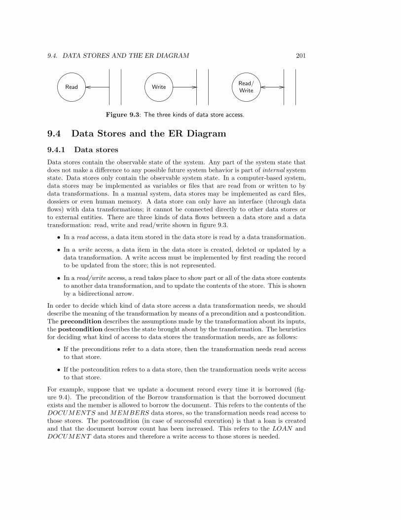
9.4. DATA STORES AND THE ER DIAGRAM 201
Read WriteRead/Write
Figure 9.3: The three kinds of data store access.
9.4 Data Stores and the ER Diagram
9.4.1 Data stores
Data stores contain the observable state of the system. Any part of the system state thatdoes not make a difference to any possible future system behavior is part of internal systemstate. Data stores only contain the observable system state. In a computer-based system,data stores may be implemented as variables or files that are read from or written to bydata transformations. In a manual system, data stores may be implemented as card files,dossiers or even human memory. A data store can only have an interface (through dataflows) with data transformations; it cannot be connected directly to other data stores orto external entities. There are three kinds of data flows between a data store and a datatransformation: read, write and read/write shown in figure 9.3.
• In a read access, a data item stored in the data store is read by a data transformation.
• In a write access, a data item in the data store is created, deleted or updated by adata transformation. A write access must be implemented by first reading the recordto be updated from the store; this is not represented.
• In a read/write access, a read takes place to show part or all of the data store contentsto another data transformation, and to update the contents of the store. This is shownby a bidirectional arrow.
In order to decide which kind of data store access a data transformation needs, we shoulddescribe the meaning of the transformation by means of a precondition and a postcondition.The precondition describes the assumptions made by the transformation about its inputs,the postcondition describes the state brought about by the transformation. The heuristicsfor deciding what kind of access to data stores the transformation needs, are as follows:
• If the preconditions refer to a data store, then the transformation needs read accessto that store.
• If the postcondition refers to a data store, then the transformation needs write accessto that store.
For example, suppose that we update a document record every time it is borrowed (fig-ure 9.4). The precondition of the Borrow transformation is that the borrowed documentexists and the member is allowed to borrow the document. This refers to the contents of theDOCUMENTS and MEMBERS data stores, so the transformation needs read access tothose stores. The postcondition (in case of successful execution) is that a loan is createdand that the document borrow count has been increased. This refers to the LOAN andDOCUMENT data stores and therefore a write access to those stores is needed.

202 CHAPTER 9. STRUCTURED ANALYSIS I: MODELS
Borrow
MEMBER
doc idreturn
date
not
avail-able
DOCUMENTS
doc id
LOANS
loan
MEMBERS
status
Figure 9.4: A read/write access.
Data stores are documented in the data dictionary by means of the conventions shownin figure 9.5. Using these conventions, we can specify for example the structure of theSTUDENTS data store as shown in figure 9.6. The data dictionary can contain otherinformation about data stores, such as the maximum and minimum expected size, expectedgrowth rate, etc.
9.4.2 The ER diagram
Figure 9.7 shows part of a DF diagram for the test registration administration. The numericlabels of the data transformations are arbitrary numbers to identify the data transforma-tions, and the letter P indicates that a data transformation is primitive (explained later).The diagram is part of a model of the following behavior of the student administration (seeapppendix B for a case description).
We can document the structure of the data stores by means of an ER diagram in whicheach data store corresponds to an entity type or to a relationship. Figure 9.8 shows an ERdiagram of the student administration that has already been discussed in chapter 8. Thebasic rule of correspondence between the ER diagram and the DF diagram is:
• Each entity type and each many-many relationship corresponds to a data store, whosename is the plural of the name of the type.
The ER diagram represents the state space of the UoD of the system as well as the statespace of the system. Viewed as a model of the system state space, entities and links aresurrogates for UoD entities and links. Existing surrogates are stored in data stores.
It is not obligatory to maintain a one-one correspondence between entity types andrelationships in the ER diagram and data stores in the DF diagram. The only requirement
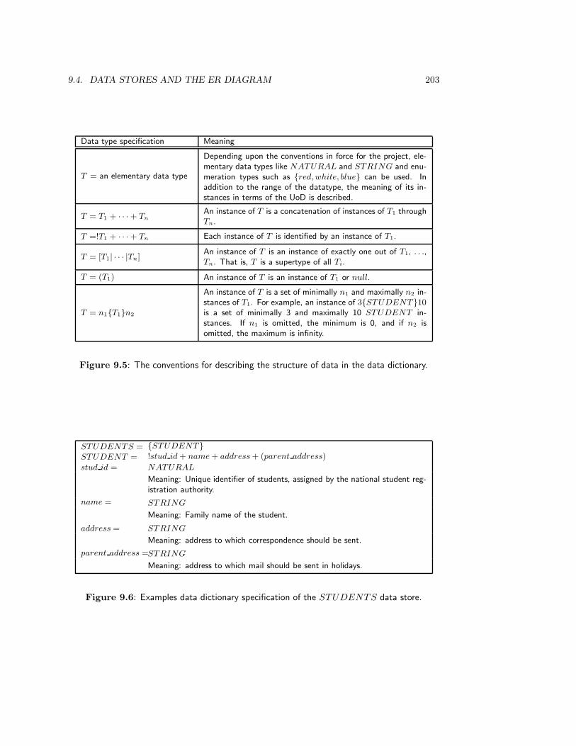
9.4. DATA STORES AND THE ER DIAGRAM 203
Data type specification Meaning
T = an elementary data type
Depending upon the conventions in force for the project, ele-mentary data types like NATURAL and STRING and enu-meration types such as {red, white, blue} can be used. Inaddition to the range of the datatype, the meaning of its in-stances in terms of the UoD is described.
T = T1 + · · · + TnAn instance of T is a concatenation of instances of T1 throughTn.
T =!T1 + · · · + Tn Each instance of T is identified by an instance of T1.
T = [T1| · · · |Tn]An instance of T is an instance of exactly one out of T1, . . .,Tn. That is, T is a supertype of all Ti.
T = (T1) An instance of T is an instance of T1 or null.
T = n1{T1}n2
An instance of T is a set of minimally n1 and maximally n2 in-stances of T1. For example, an instance of 3{STUDENT}10is a set of minimally 3 and maximally 10 STUDENT in-stances. If n1 is omitted, the minimum is 0, and if n2 isomitted, the maximum is infinity.
Figure 9.5: The conventions for describing the structure of data in the data dictionary.
STUDENTS = {STUDENT}
STUDENT = !stud id + name + address + (parent address)
stud id = NATURAL
Meaning: Unique identifier of students, assigned by the national student reg-istration authority.
name = STRING
Meaning: Family name of the student.
address = STRING
Meaning: address to which correspondence should be sent.
parent address =STRING
Meaning: address to which mail should be sent in holidays.
Figure 9.6: Examples data dictionary specification of the STUDENTS data store.
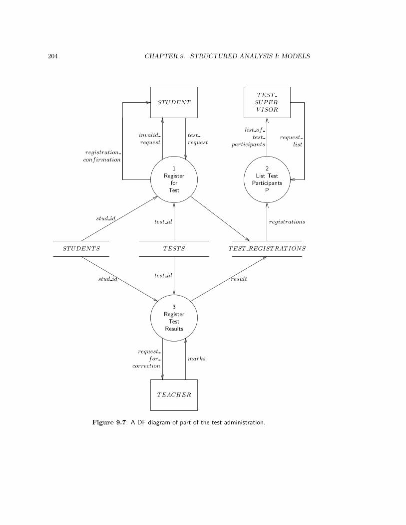
204 CHAPTER 9. STRUCTURED ANALYSIS I: MODELS
1Register
forTest
registration
confirmation
STUDENT
test
request
invalid
request
2List Test
ParticipantsP
TESTS
test id
STUDENTS
stud id
TEST REGISTRATIONS
registrations
TEST
SUPER-V ISOR
list of
test
participants
request
list
3Register
TestResults
resultstud idtest id
TEACHER
marks
request
for
correction
Figure 9.7: A DF diagram of part of the test administration.

9.4. DATA STORES AND THE ER DIAGRAM 205
STUDENT
ENROLL-MENT
PRACTI-CAL REG
TEST REG
COURSEPRACTICAL TESTcourse course
Figure 9.8: ER diagram of the student administration.
is that for each attribute of an entity type or relationship, there should be a data storein which it is stored, and for each field of a data store there should be an entity type orrelationship whose attribute it represents. There are two extremes:
• It is possible to put only one data store in the DF diagram. Each record in this storecorresponds to one existing entity or relationship, but different records in this storescan be instances of different types. This choice would lead to a badly structured datastore and a badly structured DF diagram, but it is logically possible to do this.
• It is possible to store each entity and relationship attribute in a different data store.This would also lead to a badly structured DF diagram.
One should use criteria such as minimality of interfaces between activities and data storesto find out what the optimal partitioning into data stores is.
There is some redundancy between the documentation in the data dictionary and theER diagram. For example, attributes are declared both in the data dictionary and in theER diagram. Worse, both declarations follow a different convention. Compare, for example,the definition of the name attribute in figure 9.6 with the definition of name in the ERapproach. In the ER model, name is a function
extσ(STUDENT ) → ext(STRING).
This means that we can distinguish the domain and codomain of name. In the data flowmodel, the distinction between attributes, their domains and their codomains is not made.
It is possible that external entities are part of the UoD of the system. For example,STUDENT is an external entity because it can generate events to which the system mustrespond. At the same time it is an entity type in the ER diagram, because it is part of theworld about which the system stores data. Because in the example we let ER entity andrelationship types correspond to data stores, we find a data store STUDENTS as well asan external entity STUDENT in the DF diagram.
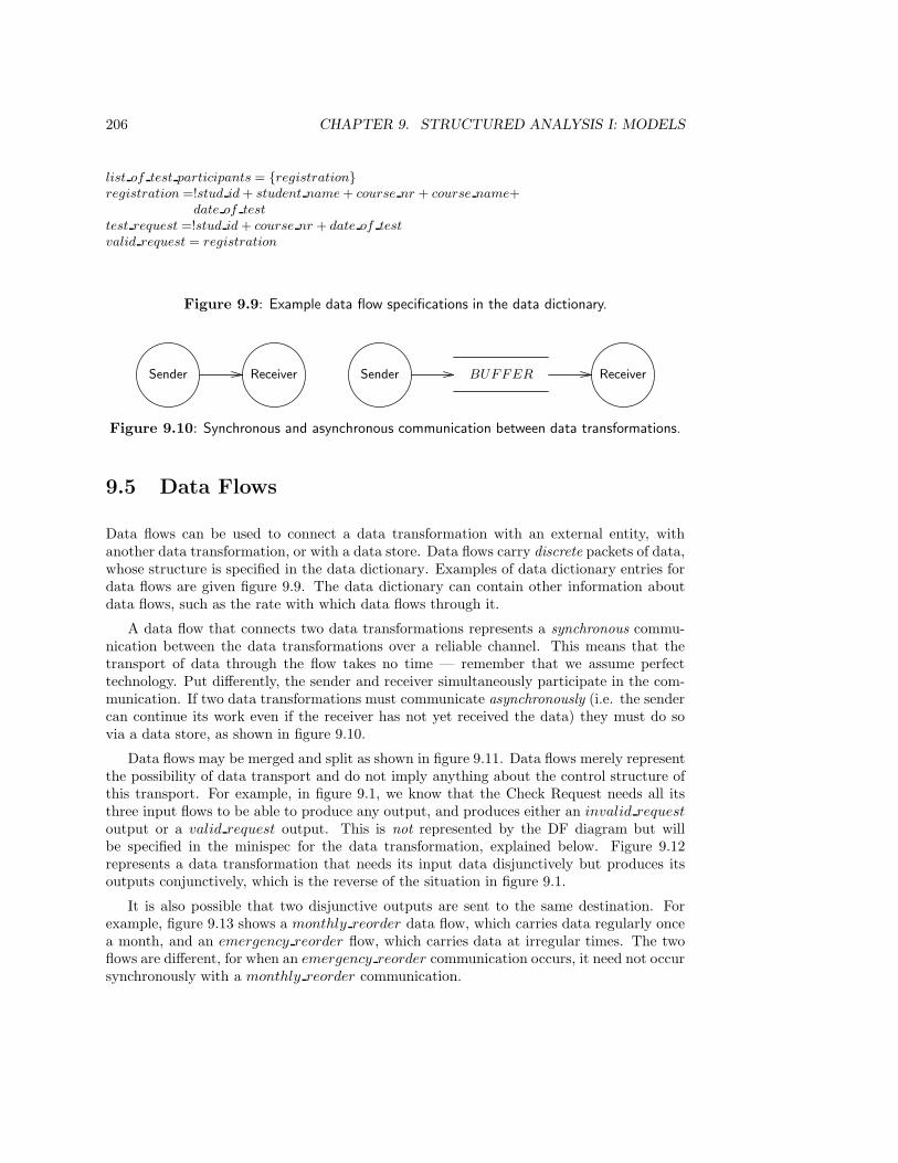
206 CHAPTER 9. STRUCTURED ANALYSIS I: MODELS
list of test participants = {registration}registration =!stud id + student name + course nr + course name+
date of test
test request =!stud id + course nr + date of test
valid request = registration
Figure 9.9: Example data flow specifications in the data dictionary.
Sender BUFFER ReceiverReceiverSender
Figure 9.10: Synchronous and asynchronous communication between data transformations.
9.5 Data Flows
Data flows can be used to connect a data transformation with an external entity, withanother data transformation, or with a data store. Data flows carry discrete packets of data,whose structure is specified in the data dictionary. Examples of data dictionary entries fordata flows are given figure 9.9. The data dictionary can contain other information aboutdata flows, such as the rate with which data flows through it.
A data flow that connects two data transformations represents a synchronous commu-nication between the data transformations over a reliable channel. This means that thetransport of data through the flow takes no time — remember that we assume perfecttechnology. Put differently, the sender and receiver simultaneously participate in the com-munication. If two data transformations must communicate asynchronously (i.e. the sendercan continue its work even if the receiver has not yet received the data) they must do sovia a data store, as shown in figure 9.10.
Data flows may be merged and split as shown in figure 9.11. Data flows merely representthe possibility of data transport and do not imply anything about the control structure ofthis transport. For example, in figure 9.1, we know that the Check Request needs all itsthree input flows to be able to produce any output, and produces either an invalid request
output or a valid request output. This is not represented by the DF diagram but willbe specified in the minispec for the data transformation, explained below. Figure 9.12represents a data transformation that needs its input data disjunctively but produces itsoutputs conjunctively, which is the reverse of the situation in figure 9.1.
It is also possible that two disjunctive outputs are sent to the same destination. Forexample, figure 9.13 shows a monthly reorder data flow, which carries data regularly oncea month, and an emergency reorder flow, which carries data at irregular times. The twoflows are different, for when an emergency reorder communication occurs, it need not occursynchronously with a monthly reorder communication.
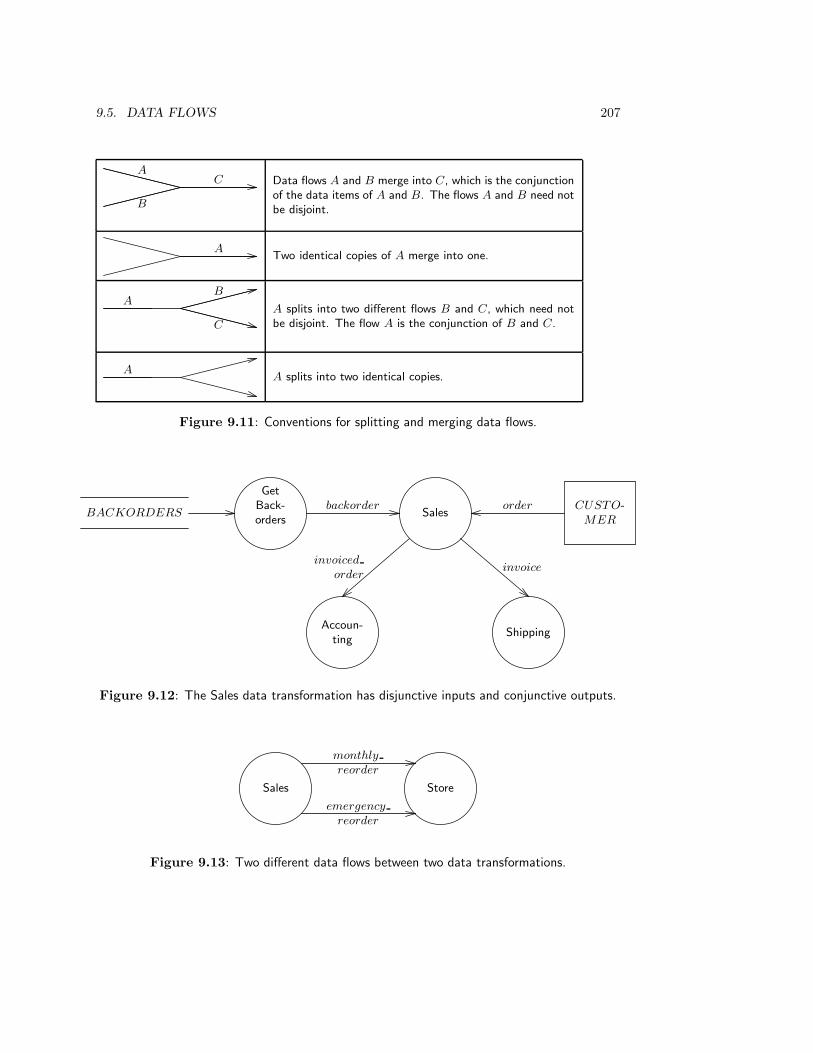
9.5. DATA FLOWS 207
CA
B
Data flows A and B merge into C, which is the conjunctionof the data items of A and B. The flows A and B need notbe disjoint.
ATwo identical copies of A merge into one.
AB
C
A splits into two different flows B and C, which need notbe disjoint. The flow A is the conjunction of B and C.
AA splits into two identical copies.
Figure 9.11: Conventions for splitting and merging data flows.
Sales
GetBack-orders
backorderBACKORDERS
CUSTO-MER
order
Accoun-ting
invoiced
order
Shipping
invoice
Figure 9.12: The Sales data transformation has disjunctive inputs and conjunctive outputs.
Sales Store
monthly
reorder
emergency
reorder
Figure 9.13: Two different data flows between two data transformations.

208 CHAPTER 9. STRUCTURED ANALYSIS I: MODELS
9.6 Data Transformations
A data transformation is an activity that manipulates data. There are two kinds of datatransformations, combinational and reactive. A combinational data transformationdoes not have a memory of its inputs once it has produced an output. If a combinationaldata transformation receives inputs I1, . . . , Im and it produces outputs O1, . . . , On, thenthe outputs are a mathematical function of its inputs:
〈O1, . . . , On〉 = f(〈I1, . . . , Im〉).
A reactive data transformation has a memory of its past inputs that influences itsresponse to current inputs. If the current state of a reactive data transformation is σ andits next state is σ′, then the outputs and next state are mathematical functions of its inputsand current state:
〈O1, . . . , On〉 = f(σ, 〈I1, . . . , Im〉) andσ′ = g(σ, 〈I1, . . . , Im〉).
A reactive data transformation must be specified in a DF model by decomposing it into aDF diagram that contains at least one data store. Note that the entire system modeled bya DF model is a reactive data transformation (assuming there is at least one data store inthe DF model).
A combinational data transformation can be specified in two ways, by a DF diagramthat does not contain a data store and by a minispec. Thus, combinational and reactivetransformations both can be specified by decomposing them into a DF diagram but onlycombinational transformations can be specified by means of minispecs. We discuss decom-position and minispecs in the next two subsections.
9.6.1 Specification by DF diagram
If a data transformation is specified by a DF diagram, we say that the data transforma-tion is decomposed into a DF diagram. Data transformation decomposition gives us ahierarchical structure of DF diagrams, that can be represented by a transformation de-composition tree. The root of the tree is a data transformation that represents the entiresystem, and the leaves of the tree are data transformations specified by means of minis-pecs. The data transformations at the leaves of the tree are also called primitive datatransformations or functional primitives. Note that all primitive transformations arecombinational.
A DF diagram that represents the entire system by one data transformation is calledthe context diagram or a level 0 diagram of the system. The data transformation inthe context diagram is called the system transformation. Figure 9.14 shows a contextdiagram for part of the student administration. The system transformation in figure 9.14is decomposed into the level 1 diagram shown in figure 9.7. Data transformations 1 and3 of the level 1 diagram are specified in figures 9.15 and 9.16. The entire transformationdecomposition tree is shown in figure 9.17.
The context diagram of a system is called the level 0 diagram of the system, and thedecomposition of the system transformation is called the level 1 diagram. A diagram thatdecomposes a data transformation at level n is itself at level n+1. The data transformationsin a level n + 1 diagram are identified by labels of the form p.k, where p is the identifier
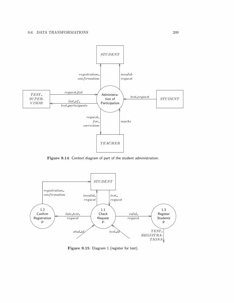
9.6. DATA TRANSFORMATIONS 209
Administra-tion of
Participation
TEST
SUPER-V ISOR
list of
test participants
request list
STUDENT
registration
confirmation
invalid-request
TEACHER
request
for
correction
marks
STUDENTtest request
Figure 9.14: Context diagram of part of the student administration.
1.1Check
RequestP
STUDENT
test
request
invalid
request
1.2Confirm
RegistrationP
registration
confirmation
late test
request
1.3RegisterStudents
P
valid
request
TEST
REGISTRA-TIONS
test idstud id
Figure 9.15: Diagram 1 (register for test).

210 CHAPTER 9. STRUCTURED ANALYSIS I: MODELS
TEACHER
3.1VerifyTotals
P
mark
request
for
correction
consistent
totals
3.2RegisterResults
P
result
test id
stud id
Figure 9.16: Diagram 3 (maintaining test results).
Administration of Participation
1Register for Test
3Register Test Results
2List Test Participants
1.1 Check Requests
1.2 ConfirmRegistration
1.3 Register Students
3.1 Verify Totals
3.2 Register Results
Figure 9.17: Transformation decomposition tree of the administration.
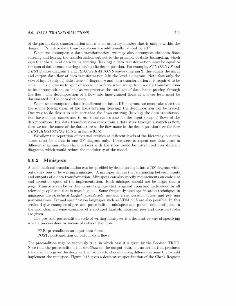
9.6. DATA TRANSFORMATIONS 211
of the parent data transformation and k is an arbitrary number that is unique within thediagram. Primitive data transformations are additionally labeled by a P.
When we decompose a data transformation, we may also decompose the data flowsentering and leaving the transformation subject to the principle of data balancing, whichsays that the sum of data items entering (leaving) a data transformation must be equal tothe sum of data items entering (leaving) its decomposition. For example, STUDENTS andTESTS enter diagram 2 and REGISTRATIONS leaves diagram 2; this equals the inputand output data flow of data transformation 2 in the level 1 diagram. Note that only thesum of input (output) data items of diagram n and data transformation n is required to beequal. This allows us to split or merge data flows when we go from a data transformationto its decomposition, as long as we preserve the total set of data items passing throughthe flow. The decomposition of a flow into finer-grained flows at a lower level must bedocumented in the data dictionary.
When we decompose a data transformation into a DF diagram, we must take care thatthe source (destination) of the flows entering (leaving) the decomposition can be traced.One way to do this is to take care that the flows entering (leaving) the data transforma-tion have unique names and to use these names also for the input (output) flows of thedecomposition. If a data transformation reads from a data store through a nameless flow,then we use the name of the data store as the flow name in the decomposition (see the flowTEST REGISTRATIONS in figure 9.15).
We allow the repetition of external entities at different levels of the hierarchy, but datastores must be shown in one DF diagram only. If we were to repeat one data store indifferent diagrams, then the interfaces with the store would be distributed over differentdiagrams, which would reduce the modularity of the model.
9.6.2 Minispecs
A combinational transformation can be specified by decomposing it into a DF diagram with-out data stores or by writing a minispec. A minispec defines the relationship between inputsand outputs of a data transformation. Minispecs can also specify requirements on code sizeand execution speed of the implementation. Each minispec should not be larger than apage. Minispecs can be written in any language that is agreed upon and understood by allrelevant people and that is unambiguous. Some frequently used specification techniques inminispecs are structured English, pseudocode, decision trees, decision tables, and pre- andpostconditions. Formal specification languages such as VDM or Z are also possible. In thissection I give examples of pre- and postcondition minispecs and pseudocode minispecs. Inthe next chapter, some examples of structured English, decision trees and decision tablesare given.
The pre- and postcondition style of writing minispecs is a declarative way of specifyingwhat a process does by means of rules of the form
PRE: precondition on input data flowsPOST: postcondition on output data flows.
The precondition may be vacuously true, in which case it is given by the Boolean TRUE.Note that the postcondition is a condition on the output data, not an action that producesthe data. This gives the designer the freedom to choose among different actions that wouldimplement the minispec. Figure 9.18 gives a declarative specification of the Check Request
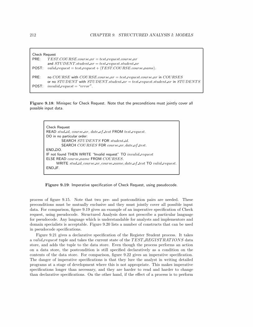
212 CHAPTER 9. STRUCTURED ANALYSIS I: MODELS
Check RequestPRE: TEST.COURSE.course nr = test request.course nr
and STUDENT.student nr = test request.student nr
POST: valid request = test request + 〈TEST.COURSE.course name〉.
PRE: no COURSE with COURSE.course nr = test request.course nr in COURSES
or no STUDENT with STUDENT.student nr = test request.student nr in STUDENTS
POST: invalid request = “error′′.
Figure 9.18: Minispec for Check Request. Note that the preconditions must jointly cover allpossible input data.
Check RequestREAD stud id, course nr, date of test FROM test request.DO in no particular order:
SEARCH STUDENTS FOR student id.SEARCH COURSES FOR course nr, date of test.
END DO.IF not found THEN WRITE “Invalid request” TO invalid request
ELSE READ course name FROM COURSES.WRITE stud id, course nr, course name, date of test TO valid request.
END IF.
Figure 9.19: Imperative specification of Check Request, using pseudocode.
process of figure 9.15. Note that two pre- and postcondition pairs are needed. Thesepreconditions must be mutually exclusive and they must jointly cover all possible inputdata. For comparison, figure 9.19 gives an example of an imperative specification of Checkrequest, using pseudocode. Structured Analysis does not prescribe a particular languagefor pseudocode. Any language which is understandable for analysts and implementors anddomain specialists is acceptable. Figure 9.20 lists a number of constructs that can be usedin pseudocode specifications.
Figure 9.21 gives a declarative specification of the Register Student process. It takesa valid request tuple and takes the current state of the TEST REGISTRATIONS datastore, and adds the tuple to the data store. Even though the process performs an actionon a data store, the postcondition is still specified declaratively as a condition on thecontents of the data store. For comparison, figure 9.22 gives an imperative specification.The danger of imperative specifications is that they lure the analyst in writing detailedprograms at a stage of development where this is not appropriate. This makes imperativespecifications longer than necessary, and they are harder to read and harder to changethan declarative specifications. On the other hand, if the effect of a process is to perform
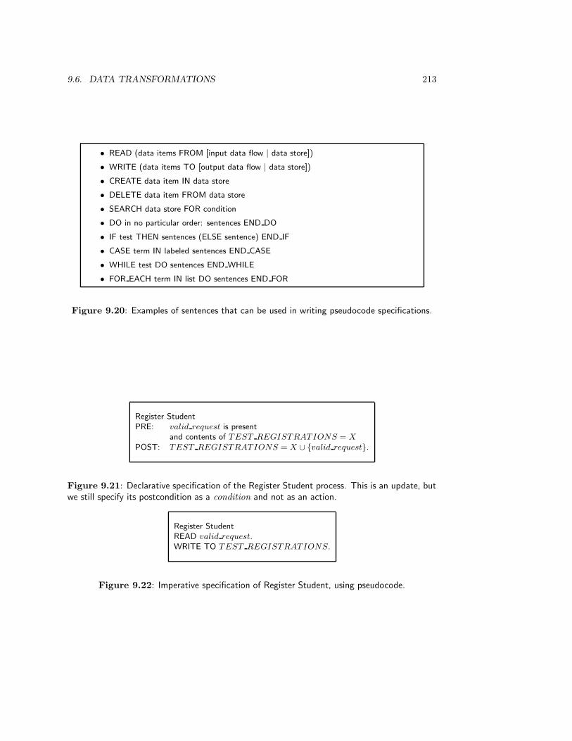
9.6. DATA TRANSFORMATIONS 213
• READ (data items FROM [input data flow | data store])
• WRITE (data items TO [output data flow | data store])
• CREATE data item IN data store
• DELETE data item FROM data store
• SEARCH data store FOR condition
• DO in no particular order: sentences END DO
• IF test THEN sentences (ELSE sentence) END IF
• CASE term IN labeled sentences END CASE
• WHILE test DO sentences END WHILE
• FOR EACH term IN list DO sentences END FOR
Figure 9.20: Examples of sentences that can be used in writing pseudocode specifications.
Register StudentPRE: valid request is present
and contents of TEST REGISTRATIONS = X
POST: TEST REGISTRATIONS = X ∪ {valid request}.
Figure 9.21: Declarative specification of the Register Student process. This is an update, butwe still specify its postcondition as a condition and not as an action.
Register StudentREAD valid request.WRITE TO TEST REGISTRATIONS.
Figure 9.22: Imperative specification of Register Student, using pseudocode.
214 CHAPTER 9. STRUCTURED ANALYSIS I: MODELS
an action, such as to update a data store, an imperative specification is usually shorter,simpler and more understandable than the corresponding declarative specification (comparefigures 9.21 and 9.22).
9.7 Methodological Analysis
9.7.1 The place of DF models in the specification framework
DF models can be used to specify the behavior of any current or desired data manipulationsystem. They ignore the most important aspect of data manipulation systems, viz. thatthey have a UoD: In DF modeling the system is specified, not its UoD. Referring to theframework for behavior specifications in figure 4.3 (page 75), DF models represent bothdimensions of system behavior, static and dynamic. Figure 9.23 details the aspects of statespace and state transition specification represented by ER and DF specifications. Briefly,the system state space is represented in a DF model by data stores and the state transitionsof the system are represented by data transformations. Some static constraints can bespecified in the data dictionary as comments on data store definitions and some dynamicconstraints on transactions can be specified as part of the documentation of external entities.It is clear from figure 9.23 that the ER model duplicates information already representedby the data stores. In addition there is information present on either side not representedby the other:
• ER models show of which entity types and relationships the existence sets are storedin the data stores. ER models also show cardinality constraints.
• DF models show what use is made of the data in the data stores. They also showwhere the data come from and where they go to.
The state transitions of the system are represented by the data transformations. In partic-ular, data transformations and their specifications represent the response of the system toevents. An event triggers one or more data transformations, which trigger other transfor-mations, so that eventually an observable response is produced. All data transformationstherefore represent observable activity of the system. A DF diagram provides the sameinformation as a list of required observable system functions (in the sense of useful interac-tions) and adds to this the following information:
• Which external entities produce or consume data during an interaction.
• Which information about past interactions is accessible to each function.
This is represented by showing how each data transformation reads information from thedata stores, and how it updates the data stores. In the simplest kind of DF diagram,each data transformation represents a single system function, contains no data stores itself,and accesses only system data stores; different transformations do not send data flows toeach other. This is shown schematically in figure 9.24. Let us call this a functional DFdiagram. In a functional diagram, there is a one-one relationship between data transfor-mations and required system functions and the transformations have no direct interfaceswith each other. The transformations are all combinational, because they have no memory.
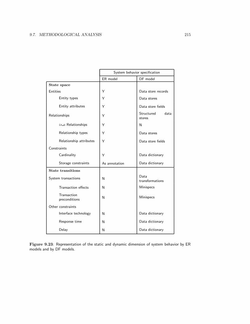
9.7. METHODOLOGICAL ANALYSIS 215
System behavior specification
ER model DF model
State space
Entities Y Data store records
Entity types Y Data stores
Entity attributes Y Data store fields
Relationships YStructured datastores
is a Relationships Y N
Relationship types Y Data stores
Relationship attributes Y Data store fields
Constraints
Cardinality Y Data dictionary
Storage constraints As annotation Data dictionary
State transitions
System transactions NDatatransformations
Transaction effects N Minispecs
Transactionpreconditions
N Minispecs
Other constraints
Interface technology N Data dictionary
Response time N Data dictionary
Delay N Data dictionary
Figure 9.23: Representation of the static and dynamic dimension of system behavior by ERmodels and by DF models.
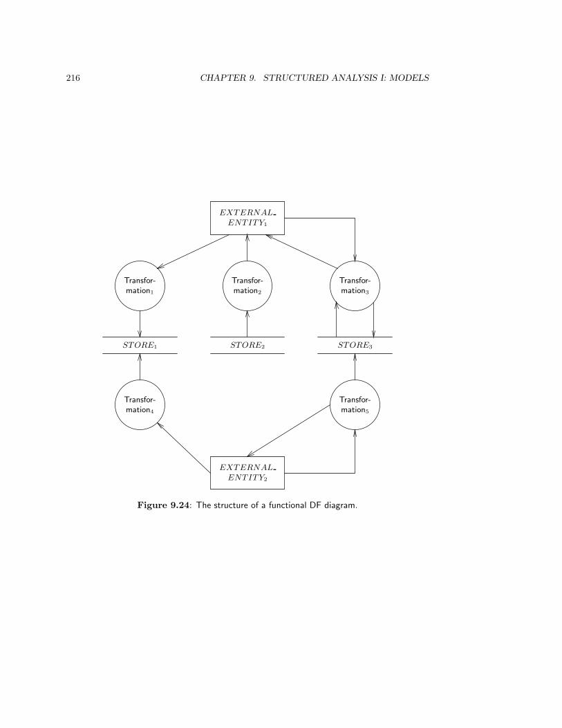
216 CHAPTER 9. STRUCTURED ANALYSIS I: MODELS
STORE1 STORE2 STORE3
Transfor-mation1
Transfor-mation2
Transfor-mation3
Transfor-mation4
Transfor-mation5
EXTERNAL
ENTITY1
EXTERNAL
ENTITY2
Figure 9.24: The structure of a functional DF diagram.

9.7. METHODOLOGICAL ANALYSIS 217
We can therefore assume that each transformation is specified by a minispec; if a trans-formation were to be decomposed into a DF diagram, then this diagram contains no datastores and we can write a minispec that specifies the same effect. Furthermore, we canalways specify a function completely by specifying two things in its minispec:
• The precondition of the function. This is a condition on the triggering event of thefunction and on the contents of the data stores that, if false, prevents the functionoccurring. If the precondition is false, the transformation responds to the event bysending a message to the environment that the function cannot be executed.
• The effect of the function. If the precondition is satisfied, the transformation respondsby updating data stores and/or sending output to the environment as required by thefunction. The effect may be specified by means of a postcondition specification, orby an imperative specification, etc. The effect is always observable. (Any update toa data store is observable because data store contents are by definition observable.)
Any DF diagram can always be brought into functional form, because this form representsthe structure of a programmable computer. At the very least, we can represent a datamanipulation system as a single data store and a single data transformation, representingthe memory and processor of a computer, respectively. This represents the system as asingle, complicated function with a single, complicated memory. In practice, we can usuallydo better than that and distinguish several orthogonal system functions. In any case, a DFmodel represents a system as a collection of functions, each of which has a precondition andan effect.
9.7.2 Transactions
Figure 9.23 defines the dynamic aspect of the system as consisting of transactions (usefulinteractions with the environment that are atomic) rather than functions (useful interactionswith the environment that are not necessarily atomic). DF models do not represent systemtransactions but system functions — indeed, data transformations are often called functionsby some authors. There is nothing in the concept of data transformation that forces us to useit to represent transactions. Nevertheless, even if transformations do not always representtransactions, an entire DF model represents system behavior as consisting of transactions.We explain this in the next paragraphs.
A transaction is represented in a DF model as consisting of an event generated by the en-vironment and a response generated by the system. The atomicity property of transactionsis satisfied because a DF model assumes a system implemented by means of perfect technol-ogy, which means that data transformations perform their task at infinite speed, data storeshave unlimited capacity, and data access is instantaneous. This means that the response toan event occurs synchronously to the event! We call this the synchronicity assumptionof DF modeling. It simplifies the representation of the system considerably. In practice,it means that the processes that will implement a transaction must be sufficiently fast ascompared with the speed with which the environment produces events, so that the process-ing speed can be neglected. The synchronicity assumption leads to important constraintson the implementation of control systems, where the environment may produce events at avery high rate and these events must not be lost by the system.
An essential DF diagram is a is a functional DF diagram in which each transformationrepresents a single system transaction. An essential DF model is a model in which the
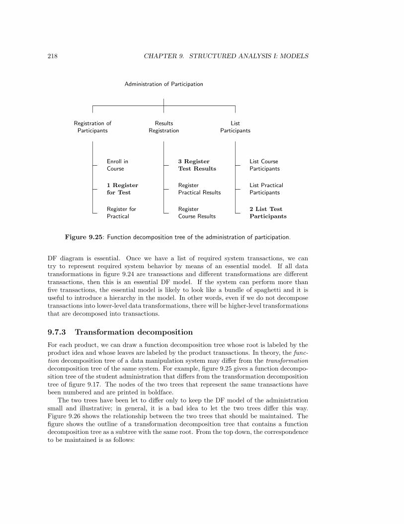
218 CHAPTER 9. STRUCTURED ANALYSIS I: MODELS
Administration of Participation
Registration ofParticipants
ResultsRegistration
ListParticipants
Enroll inCourse
1 Registerfor Test
Register forPractical
3 RegisterTest Results
RegisterPractical Results
RegisterCourse Results
List CourseParticipants
List PracticalParticipants
2 List TestParticipants
Figure 9.25: Function decomposition tree of the administration of participation.
DF diagram is essential. Once we have a list of required system transactions, we cantry to represent required system behavior by means of an essential model. If all datatransformations in figure 9.24 are transactions and different transformations are differenttransactions, then this is an essential DF model. If the system can perform more thanfive transactions, the essential model is likely to look like a bundle of spaghetti and it isuseful to introduce a hierarchy in the model. In other words, even if we do not decomposetransactions into lower-level data transformations, there will be higher-level transformationsthat are decomposed into transactions.
9.7.3 Transformation decomposition
For each product, we can draw a function decomposition tree whose root is labeled by theproduct idea and whose leaves are labeled by the product transactions. In theory, the func-tion decomposition tree of a data manipulation system may differ from the transformationdecomposition tree of the same system. For example, figure 9.25 gives a function decompo-sition tree of the student administration that differs from the transformation decompositiontree of figure 9.17. The nodes of the two trees that represent the same transactions havebeen numbered and are printed in boldface.
The two trees have been let to differ only to keep the DF model of the administrationsmall and illustrative; in general, it is a bad idea to let the two trees differ this way.Figure 9.26 shows the relationship between the two trees that should be maintained. Thefigure shows the outline of a transformation decomposition tree that contains a functiondecomposition tree as a subtree with the same root. From the top down, the correspondenceto be maintained is as follows:
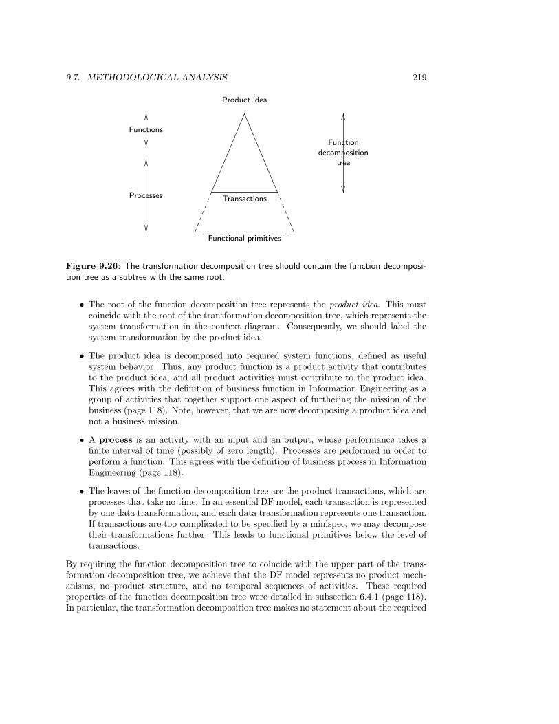
9.7. METHODOLOGICAL ANALYSIS 219
Product idea
Functions
Processes Transactions
Functional primitives
Functiondecomposition
tree
Figure 9.26: The transformation decomposition tree should contain the function decomposi-tion tree as a subtree with the same root.
• The root of the function decomposition tree represents the product idea. This mustcoincide with the root of the transformation decomposition tree, which represents thesystem transformation in the context diagram. Consequently, we should label thesystem transformation by the product idea.
• The product idea is decomposed into required system functions, defined as usefulsystem behavior. Thus, any product function is a product activity that contributesto the product idea, and all product activities must contribute to the product idea.This agrees with the definition of business function in Information Engineering as agroup of activities that together support one aspect of furthering the mission of thebusiness (page 118). Note, however, that we are now decomposing a product idea andnot a business mission.
• A process is an activity with an input and an output, whose performance takes afinite interval of time (possibly of zero length). Processes are performed in order toperform a function. This agrees with the definition of business process in InformationEngineering (page 118).
• The leaves of the function decomposition tree are the product transactions, which areprocesses that take no time. In an essential DF model, each transaction is representedby one data transformation, and each data transformation represents one transaction.If transactions are too complicated to be specified by a minispec, we may decomposetheir transformations further. This leads to functional primitives below the level oftransactions.
By requiring the function decomposition tree to coincide with the upper part of the trans-formation decomposition tree, we achieve that the DF model represents no product mech-anisms, no product structure, and no temporal sequences of activities. These requiredproperties of the function decomposition tree were detailed in subsection 6.4.1 (page 118).In particular, the transformation decomposition tree makes no statement about the required

220 CHAPTER 9. STRUCTURED ANALYSIS I: MODELS
system architecture. This parallels the independence of the function decomposition tree ofa business from the decomposition of the business into subsystems, noted in the method-ological discussion of ISP (page 132). Transformation decomposition stays at one level ofaggregation in the development framework, system decomposition moves one level down.
All that is represented by the DF model of a system is that in order to perform a certainactivity (data transformation), certain other activities must be performed (indicated by thedecomposition of the data transformation). Conversely, the only reason for the presence ofa data transformation lies in the fact that a higher-level transformation must be performed.The function decomposition tree thus represents a truly essential model of required systembehavior.
Note that the activity of the system below the level of transactions is represented inmore detail by the transaction decomposition table. For example, figure 8.8 (page 173)shows which data are created, read, updated or deleted as part of the transactions of thestudent administration. The part of the tree below the level of transactions shows howthese sub-transaction processes produce and consume data.
9.8 Summary
A complete data flow model consists of the following components:
• A set of data flow diagrams.
• The corresponding process decomposition tree.
• Minispecs for the primitive processes.
• An ER diagram that represents the structure of the data stores.
• A data dictionary that contains the definitions of all names used in the model.
DF models partition the observable behavior of a system into activities called data trans-formations, which may change the system state as contained in the data stores, and whosebehavior may depend upon the contents of the data store. The system communicates withits environment by data flows. The entire system is specified by the system transformationin the context diagram. This is decomposed into a DF diagram, whose transformation maybe further decomposed into DF diagrams. The resulting hierarchical structure is representedby the transformation decomposition tree. The leaves of the tree are transformations thatmust be specified by minispecs.
The behavior of a system is represented by decomposing each transaction into an externalevent and a response to that event. External events can be generated by external entitiesor by the passage of time, in which case they are called temporal events. An event andits response together form a system transaction. Because of the atomicity property oftransaction, a response is considered to occur simultaneously with its event.
The ER diagram of an ER model duplicates some information present in a DF diagram,but adds the information what the entity types and relationships are whose existence setsare stored in the data stores. For each entity type and for each relationship, the existenceset should be stored in one or more system data stores; conversely, each data store shouldcontain at least part of the existence set of at least one entity type or relationship. The DFdiagram shows what kind of access the data transformations have to the data stores.
9.9. EXERCISES 221
In a functional DF model, all data transformations correspond one-one with the re-quired system functions, and the activities do not interface with each other. If the activitiescorrespond one-one with required system transactions, we call it an essential DF model.The transformation decomposition tree should be made to contain the function decompo-sition tree of the system so that both trees share their root. The leaves of the functiondecomposition tree are data transformations that represent required system transactions;the transformation decomposition tree can further decompose these transformations intoDF diagrams that accomplish the tasks listed in the transaction decomposition table.
9.9 Exercises
1. In figure 9.8, TEST REGISTRATION really represents three events in the UoD:registering for a test, doing the test, and receiving a mark. An attribute of theregistration event is date registered, an attribute of doing the test is date of test andan attribute of receiving a mark is result. Change the ER diagram to represent thesethree events. Then adapt the DF diagram of the test registration so that each datastore in the changed DF diagram corresponds to exactly one entity- or relationshiptype in the changed DF diagram.
2. (a) Draw an essential DF diagram of the student administration that represents thetransactions of the functions Registration of Participants and Results Registra-tion, shown in figure 9.25.
(b) Abstract from this model a higher-level functional DF diagram that contains thetwo transformations corresponding to the functions Registration of Participantsand Results Registration.
3. The DF diagram notation can also be used to represent material manipulations. As-sume that we use thick lines to represent flows, transformations and stores of material.
(a) Discuss the difference in behavior between flows, transformations and stores ofdata on the one hand and flows, transformations and stores of material on theother.
(b) Suppose that we use dashed lines to represent energy flows, transformations andstores. Discuss the difference with data flows, transformations and stores.
4. Build data and/or material flow diagrams of the following processes. If there aretemporal events, identify these. Try to build functional models.
(a) To fill in my income tax form, I collect the yearly salary statement of my em-ployer, leaf through a book with the latest tax-deduction tricks, gather the billsof deductible expenses of one year, fill in the form, use the income tax tables tocompute the income tax return I am entitled to, copy the filled out form andsend it to the income tax department.
(b) A thermostat reads a sensor that indicates the current room temperature, acceptsdata from an input device that tells it what the desired room temperature is,and can send a signal to a heater to switch on and off. List the transactions ofthis control system and make a functional DF diagram.

222 CHAPTER 9. STRUCTURED ANALYSIS I: MODELS
(c) To wash clothes, they are separated into machine-washable clothes, hand-washableclothes, and clothes that must be cleaned chemically. The machine-washableclothes are separated into white and colored clothes to be washed separately.Hand-washable clothes are put aside to be done later and clothes to be cleanedchemically are put on another pile. After washing, the clothes are separated intothose that can be put in the tumble dryer and those that must be hung to dry.After drying, the clothes are folded and put in cupboards.
9.10 Bibliographical Remarks
The importance of data flow modeling for business problem analysis was already realizedin the early 1960s. Two early references which recognized this need are Gatto [110] andMiller [230]. The DF modeling notation received wide attention after papers by Ross andBrackett [293] and Ross [291] were published in 1976 and 1977. This notation distinguishesinput flows into data input and control, and additional uses an flow to represent the mech-anism by which the transformation is carried out. It became known as the StructuredAnalysis and Design Technique (SADT). Marca and Gowan published a book about this in1988 [210].
The DF notation discussed in this chapter is a simplification of the SADT notation andwas introduced in the late 1970s by DeMarco [84], V. Weinberg [358], Gane and Sarson [108],and Yourdon and Constantine [378]. DeMarco introduced the concept of leveling.
The use of ER models in combination with DF modeling is promoted in the early 1980sby Flavin [105]. The DF-ER modeling notation reached its final form in the late 1980s in abook by Yourdon [376]. Kowal [185] and Goldsmith [118] give good surveys of the combinedDF-ER modeling approach.
The concept of essential model is due to McMenamin and Palmer [225]. Reactive systemsare defined by Manna and Pnueli [209] and by Harel and Pnueli [140]; they are calledplanned response systems by McMenamin and Palmer. The synchronicity assumption isdue to Berry and Cosserat [31] and is called the synchrony hypothesis by them.

Chapter 10
Structured Analysis II: Methods
10.1 Introduction
Structured analysis (SA) was developed in a period in which manual administrations wereautomated for the first time. The computerized administrations had roughly the same func-tionality as the manual ones, but they could perform these functions faster. Consequently,the dominant method for finding a DF model of a SuD is to first model the current admin-istration, abstract an essential model from this, and reimplement this as a computerizedadministration (figure 10.1). This is the method of essential system modeling discussed insubsection 10.2.1.
When DF models were used to specify requirements for control systems, it was found thatthere is no current manual system to be modeled first; instead, there are interface agreementswith other engineering groups in which the transactions with other systems are laid down. Asecond method to find DF models therefore emerged, called event partitioning, in which theDF model is built starting from a list of event-response pairs that represent the requiredtransactions with the environment. A refinement of this method, called process analysisof transactions, starts from the transaction decomposition table and builds the DF modelfrom there. These methods are discussed in subsections 10.2.2 and 10.2.3. Section 10.3lists the evaluation methods used in structured analysis. In section 10.4, we take a brieflook at system decomposition and in section 10.5 we analyze structured analysis from amethodological point of view.
10.2 Methods to Find a DF Model
10.2.1 Essential system modeling
Figure 10.2 shows the structure of system development by essential system modeling. Thecurrent (manual or computer-based) system is modeled, including all its physical details.In the physical model, all model components are named after the physical entities thatimplement the component. Data transformations represent activities or processors (humanor machine) that perform the activities.
The components of a physical DF model receive the names that are actually in use in
223
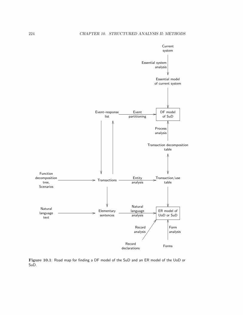
224 CHAPTER 10. STRUCTURED ANALYSIS II: METHODS
Functiondecomposition
tree,Scenarios
TransactionsTransaction/use
tableEntity
analysis
Transaction decompositiontable
Naturallanguage
text
Elementarysentences
ER model ofUoD or SuD
Naturallanguageanalysis
Recorddeclarations
Recordanalysis
Forms
Formanalysis
Processanalysis
DF modelof SuD
Essential modelof current system
Essential systemanalysis
Currentsystem
Event–responselist
Eventpartitioning
Figure 10.1: Road map for finding a DF model of the SuD and an ER model of the UoD orSuD.

10.2. METHODS TO FIND A DF MODEL 225
Current system
Makeobservations
Current physicalsystem model
Specifyessentialsystem
Current essentialsystem model
Specifyrequirements
Desired essentialsystem model
Makeimplementationdecisions
Desired physicalsystem model
Implement
Future system
Figure 10.2: System development by essential system modeling.
• Assign logical names to the model elements.
• Flatten the DF diagram hierarchy.
• Remove unnecessary communication infrastructure.
• Remove unnecessary administrative activity.
• Partition into activity fragments.
• Integrate essential activity fragments by joining data flows and data stores.
Figure 10.3: Essential system modeling heuristics.
the current system and which may indicate the current implementation technology. Thus,a transformation may be called “Monday morning’s work”, “Bob’s speciality” or “Alice”.Data stores may be called “In-box” or “Green cabinet” and data flows may have namessuch as “pink form” or “customer’s copy”. The resulting DF diagram is called the currentphysical model. Since it describes the current system exactly as it is and uses namesborrowed from those currently doing the work, it should be easy to build and verify thismodel. If the current system is manual, the current physical model represents the flow ofpaper documents through the organization.
The current system model describes the system as it is currently implemented, and there-fore contains activities, flows and stores that are due to current, imperfect implementationtechnology. We now eliminate all traces of current technology by extracting an essentialmodel from the current physical model. Figure 10.3 lists the heuristics of essential systemmodeling. These should be followed in the order listed.
• Remove nonlogical naming. Any indication of persons, departments, locations,
226 CHAPTER 10. STRUCTURED ANALYSIS II: METHODS
material, machines etc. is eliminated by choosing names that only describe the datathat are manipulated, transported or stored. As a result, all transformations, flowsand stores have logical names.
• Remove inessential partitioning into tasks. The partitioning of the current sys-tem into data transformations may be the result of historical contingencies, powergames and other imperfections of the real world. For example, the sales departmentmay maintain a shadow financial admininistration because in the past the depart-ment manager did not trust the financial department. By flattening the DF diagramhierarchy, current boundaries between task groupings dissolve.
• Remove unnecessary communications infrastructure. There may be a com-munications infrastructure in place that deals purely with imperfect implementationtechnology. For example, one department, person or machine may process its inputsso slowly that inputs sent to it from other departments have to be batched. Thisis visible as a data store in the DF diagram that would be unnecessary with perfectimplementation technology. Other communication tasks that are the result of im-perfect implementation technology are formatting, translation, sorting, merging etc.,that take place to make data produced by one subsystem ready for consumption byanother subsystem. All these communication tasks must be removed from the cur-rent system model by assuming that the system is implemented using infinitely fastprocessors and infinitely large data stores.
• Remove unnecessary administrative activities. There may be administrativeactivities in the system that are due to imperfect implementation structures. Forexample, one activity performed by the system may correct errors in data receivedfrom another activity performed by the system. Since the system is now assumed tobe perfect, this kind of error correction is unnecessary and must be removed. Otherexamples of such unnecessary activities are checking whether input received fromsome system activity conforms to certain standards, auditing the correct performanceof these checks, measuring the performance of the system, monitoring and regulatingresource use, maintaining transaction logs, writing backup files, etc.
• Partition the model into activity fragments. Those data transformations thatare part of the response to an event are grouped together into an activity fragment.This is the method of event partitioning, discussed in the next subsection. The activityfragments may still contain some traces of current implementation technology, suchas unnecessary sequencing of data transformations, unnecessarily complex access todata stores, and storing multiple copies of data in different places. These traces mustbe removed.
• Integrate essential activity fragments. The resulting activity fragments are gluedtogether at the data stores and data flows, and the integrated DF diagram should begiven a logical hierarchical structure.
Once we have an essential model of the current system, we transform it into an essentialmodel of the required system. We then make implementation decisions on the basis of theavailable technology, specify a physical model of the desired system, and implement this.

10.2. METHODS TO FIND A DF MODEL 227
1. Build the context diagram.
(a) Understand the purpose of the system.
(b) Identify the external entities.
(c) Define the data flows entering and leaving the system.
(d) Check the context diagram.
2. Build an event list.
(a) List the events in the environment to which the system must respond.
(b) For each event, list the response of the system to the event.
(c) Classify each response as data-intensive or as control-intensive.
3. Build a behavioral model.
(a) Build a DF fragment for each event-response pair.
• Define one data transformation for each event-response pair. Usually thetransformation is named after the response of the system to the event.
• Connect each response transformation to external entities that must sensethe response.
• If the response depends upon the current state of the system, connect theresponse transformation with a read data flow to the data store that holdsthe relevant part of the state.
• If the response involves a change of state of the system, connect the responsetransformation with a write data flow to the relevant data store.
(b) Merge the diagrams.
(c) Divide the DF diagram into levels.
(d) Complete the data dictionary.
(e) Add implementation constraints.
Figure 10.4: Event partitioning.
10.2.2 Event partitioning
During essential system modeling, we are asked to partition the current system modelinto activity fragments that each deal with one event. This technique became known asevent partitioning. It can be used not only to model current systems, but also to modelfuture systems, and it is applicable to data-intensive as well as control-intensive systems.Figure 10.4 shows the tasks of event partitioning as listed by Goldsmith [118]. The basicidea of event partitioning is to identify external entities, identify data flows between theSuD and the external entities, identify events that lead to input flows, and draw a DFfragment for each event that shows how the input flows lead to the output flows. To dealwith temporal events, the procedure should be completed by additionally starting from eachsystem response and reasoning back to the event that triggered the response. The procedureis likely to iterate over the tasks listed in figure 10.4 until a satisfactory model is found. In

228 CHAPTER 10. STRUCTURED ANALYSIS II: METHODS
Administra-tion of
Participation
TEST
SUPER-V ISOR
list of
test participants
TEACHER
request
for
correction
marks
STUDENTtest request
Figure 10.5: Initial context diagram of part of the student administration, that shows onlythe major data flows in each transaction.
Event Response
Student requests participation in a test Register for test
Time to produce result lists Produce result listsAdministration requests list of test participants Produce list of test participants· · · · · ·
Figure 10.6: Part of an event list for the student administration.
the beginning, only normal events and responses should be considered. The occurrence oferrors and exceptional conditions must be considered later.
To give an example, the initial context diagram for the student administration systemcould look like figure 10.5. Later iterations would improve this diagram. Part of theevent list for the same administration is shown in figure 10.6. The procedure of figure 10.4recommends classifying each event-response pair as data-intensive or control-intensive. Thisis a heuristic to determine whether, as a next step, we should build a DF model or a statetransition diagram first. In this book we do not treat state transition diagrams, so we omitthis part. (State transition diagrams and related notations are important for modelingcontrol systems and are treated in Requirements Engineering: Semantic, Real-Time andObject-Oriented Methods.) Figure 10.7 shows the DF fragment built for the event-responsepair “Student requests to perform a test – register for test”. Note that it does not yetproduce a response invalid request, since we decided to deal with error conditions later.
10.2.3 Process analysis of transactions
Process analysis of transactions is a refinement of event partitioning that takes carethat we produce mutually consistent ER and DF models (cf. the road map in figure 10.1).It is based upon the assumption that each event-response pair is a system transaction

10.2. METHODS TO FIND A DF MODEL 229
1Register
forTest
STUDENT
test
request
registration
confirmation
TESTS
test id
STUDENTS
stud id
TEST REGISTRATIONS
Figure 10.7: DF diagram fragment that deals with the event-response pair “Student requeststo perform a test – Register for Test’.
and that each system transaction is an event-response pair. We start from the transactiondecomposition table of the student administration shown in chapter 8 (figure 8.8, page 173).Figure 10.7 shows the DF fragment that deals with the transaction Register for Test. Notethat the R and C entries in the Register for Test row indicate exactly which data storeaccess must be represented in the DF diagram.
10.2.4 Case study: The Circulation Desk
Figure 10.9 gives the transaction decomposition table that corresponds to the transac-tion/use table given in chapter 8, figure 8.11 (page 175). For simplicity, the documentreservation transaction and the FINE entity type have been omitted. In addition, not allsituations in which a fine can be created are modeled.
We classified the circulation transactions into three groups and merged the DF fragmentsof each group as shown in the function decomposition tree of figure 10.10. Note that theroot of this tree represents the product idea of a system for the administration of thecirculation of documents. Since this is the task of the circulation department of the library,the decomposition tree of this function is a subtree of the function decomposition tree ofthe library, shown in figure 8.10. The DF diagrams of the three functions Reservation,Borrowing and Document loss are shown in figures 10.11, 10.12 and 10.13. Figure 10.14gives the level 1 diagram and figure 10.15 shows the context diagram. Because the level1 diagram merges some data flows of the Borrowing function, figure 10.14 shows a datadictionary entry that defines the connection between the higher and lower level data flows.Minispecs for the functional primitives of the DF model using various notations are givenin figures 10.16 to 10.22. The DF diagrams and minispecs do not deal with errors orexceptional conditions.
The minispec for Lend Document uses a decision tree. This is a useful technique for

230 CHAPTER 10. STRUCTURED ANALYSIS II: METHODS
List practical participationList test participationList course participationRegister practical resultRegister course resultRegister test resultRegister for practicalRegister for test
Enroll in course
COURSE R R
ENROLLMENT C U U
PRACTICAL R R
PRACTICAL REG C U R
STUDENT R R R R R R
TEST R R
TEST REG C U R
Figure 10.8: Transaction decomposition table for the student administration.
Required system transactions
Reservetitle
Canceltitle re-serva-tion
Lenddocu-ment
Takein docu-ment
Send re-minder
Extenddocu-mentloan
Losedocu-ment
DOCU -MENT
R U
FINE C
LOAN C D RU RU RD
LOSS C
MEMBER R R R R
TITLE R
T RESER-V ATION
C D RD R
Figure 10.9: Transaction decomposition table of some transactions of the circulation admin-istration.

10.2. METHODS TO FIND A DF MODEL 231
Administration of document circulation
Reservation Borrowing Document loss
1 Reserve title
2 Cancel reservation
3 Lend document
4 Take in document
5 Send reminder
6 Extend document loan
7 Lose document
Figure 10.10: Function decomposition tree of the administration of document circulation.
1Reserve
title
MEMBER
title id
MEMBERS
status
DOCUMENTS
doc id +availability
T ITLES
title id
T RESERV ATIONS
2Cancel
title reser-vation
title id
Figure 10.11: DF diagram the Reservation function.
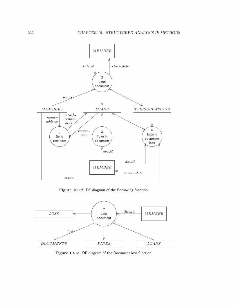
232 CHAPTER 10. STRUCTURED ANALYSIS II: METHODS
3Lend
document
MEMBER
title id return date
MEMBERS
status
LOANS T RESERV ATIONS
4Take in
document
MEMBER
doc id
5Send
reminder
name+address
6Extend
documentloan
doc id
return date
nr of
remin-ders
return
date
status
Figure 10.12: DF diagram of the Borrowing function.
7Lose
documentMEMBER
title id
FINESDOCUMENTS
lost
LOANS
LOSS
Figure 10.13: DF diagram of the Document loss function.
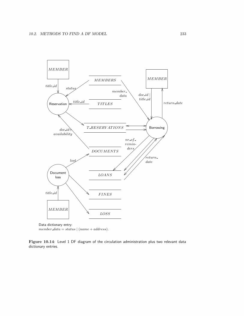
10.2. METHODS TO FIND A DF MODEL 233
MEMBERS
TITLES
T RESERV ATIONS
DOCUMENTS
LOANS
FINES
LOSS
Reservation
status
title id
doc id+availability
Documentloss
lost
Borrowing
member
data
nr of
remin-ders
return
date
MEMBER
title id
MEMBER
return date
doc id |title id
MEMBER
title id
Data dictionary entry:member data = status | (name + address).
Figure 10.14: Level 1 DF diagram of the circulation administration plus two relevant datadictionary entries.
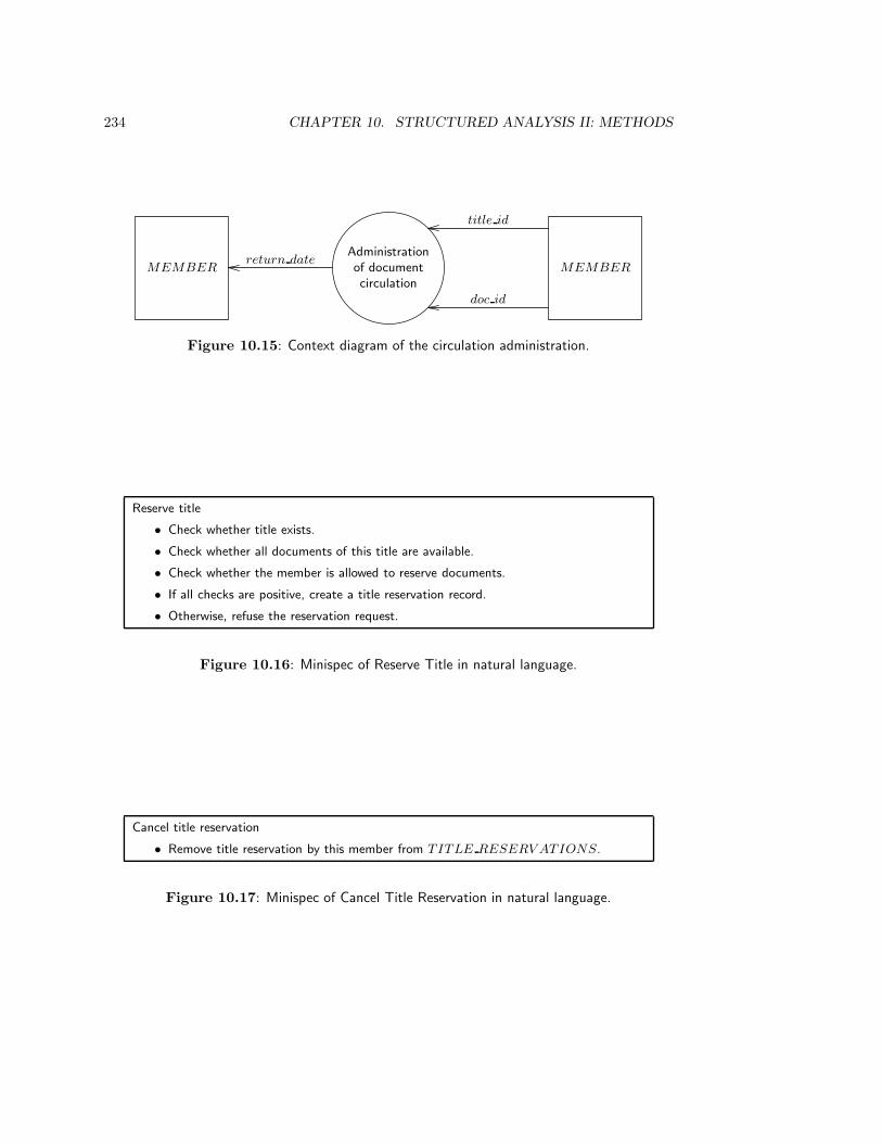
234 CHAPTER 10. STRUCTURED ANALYSIS II: METHODS
Administrationof documentcirculation
MEMBERMEMBER
title id
return date
doc id
Figure 10.15: Context diagram of the circulation administration.
Reserve title
• Check whether title exists.
• Check whether all documents of this title are available.
• Check whether the member is allowed to reserve documents.
• If all checks are positive, create a title reservation record.
• Otherwise, refuse the reservation request.
Figure 10.16: Minispec of Reserve Title in natural language.
Cancel title reservation
• Remove title reservation by this member from TITLE RESERV ATIONS.
Figure 10.17: Minispec of Cancel Title Reservation in natural language.
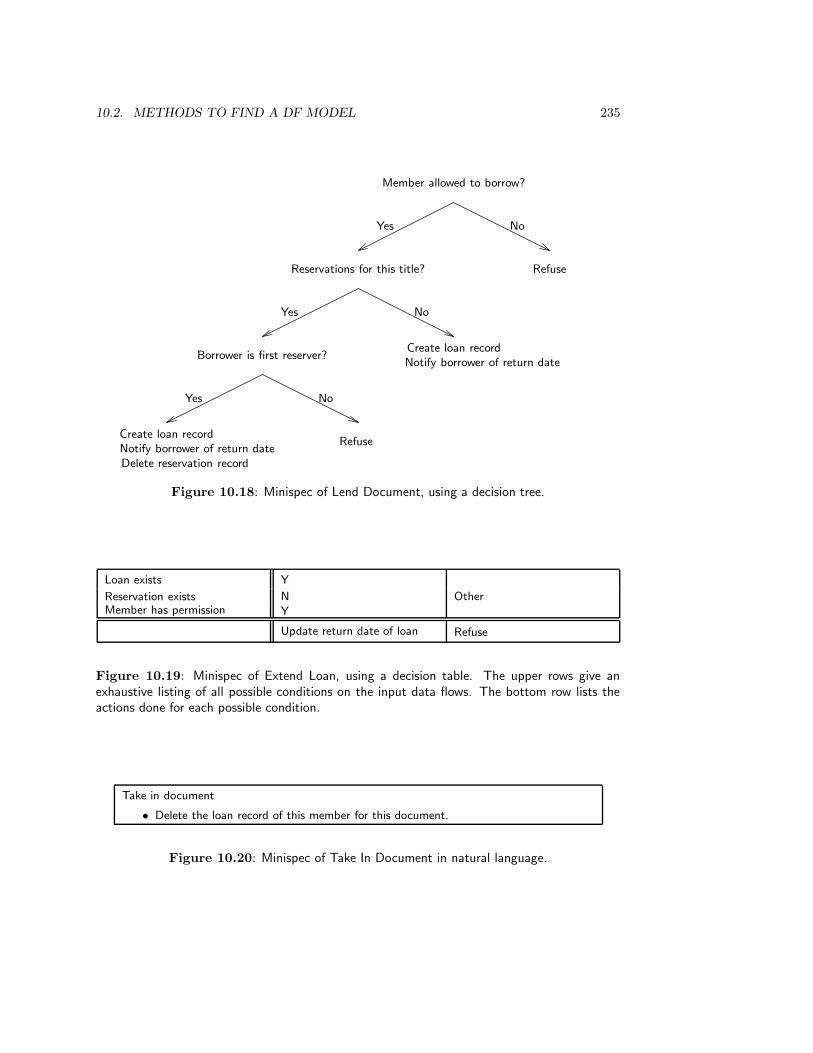
10.2. METHODS TO FIND A DF MODEL 235
Member allowed to borrow?
Reservations for this title? Refuse
Yes No
Borrower is first reserver?Create loan recordNotify borrower of return date
Yes No
Create loan recordNotify borrower of return dateDelete reservation record
Refuse
Yes No
Figure 10.18: Minispec of Lend Document, using a decision tree.
Loan exists Y
Reservation exists N OtherMember has permission Y
Update return date of loan Refuse
Figure 10.19: Minispec of Extend Loan, using a decision table. The upper rows give anexhaustive listing of all possible conditions on the input data flows. The bottom row lists theactions done for each possible condition.
Take in document
• Delete the loan record of this member for this document.
Figure 10.20: Minispec of Take In Document in natural language.

236 CHAPTER 10. STRUCTURED ANALYSIS II: METHODS
Send reminder
• Read all overdue loans from LOANS.
• Produce for each loan a record containing the loan identification, the member nameand address, and the return date for this loan.
• Update each overdue loan record by increasing the count of the number of reminderssent.
Figure 10.21: Minispec of Send Reminder in natural language.
Lose document
• Update document record with flag indicating that it is lost.
• Create fine record.
• Create loss record.
• Delete loan record.
Figure 10.22: Minispec of Lose Document in natural language.
specifying data transformations with a complex decision logic. A disadvantage of decisiontrees is that actions that must occur under several conditions may have to be repeated.The minispec for Extend Loan uses a decision table. This has been done for illustrativepurposes, for the transformation is so simple that we do not need a decision table to specifyit. Decision tables are useful if an exhaustive enumeration of all possible conditions isneeded. A disadvantage of decision tables is that they tend to become voluminous, so thatthe overall picture becomes obscured.
10.3 Methods to Evaluate a DF Model
10.3.1 Walkthroughs and inspections
If a data flow model represents the current system, it can be validated by doing observationsof this system and comparing them with the model. If the model represents a future system,no observations can be made and we must resort to other means, such as walkthroughs. Awalkthrough is a peer review of a product specification. Walkthroughs are the traditionalway of validating DF models in structured analysis. In its simplest form, a walkthrough isa meeting of developers and user representatives, in which someone very familiar with themodel walks through the model. This may be the model builder but it may also be someonewho studied the model in detail before the meeting. Any errors or mistakes in the modelare noted, but not discussed. The model builder corrects them later on and, if necessary,the revised model is subjected to a second walkthrough. In order for the walkthrough notto become a walkover, the topic of the walkthrough must be focused on the model, not onthe builder of the model. Participants in the walkthrough must not stand in a hierarchical

10.3. METHODS TO EVALUATE A DF MODEL 237
relation with the model builder.Inspections are a more formal variant of walkthroughs defined by Fagan [99, 100], in
which the participants use a list of features to be checked in the specification. Inspectionsare part of a learning cycle, in which the model builder may be sent to courses to learn extraskills, and in which company practices are updated according to the results of inspectionmeetings.
10.3.2 Simulation and animation
A completely documented DF model can be executed by a suitable processor. The modelbuilder can simulate the behavior of the specified system by simulating an event and fol-lowing the data through the system until the response is produced. The same can also bedone by a software interpreter. A simulation of a single system transaction consists of asequence of alternating system states and system actions.
• Each system state is a snapshot of the simulation, consisting of the contents of allsystem data stores and the contents of all data flows.
• Each system action in the simulation is the firing of one primitive data transformation.
In the initial state of the simulation, all data flows are empty, except the input data flowsthat are filled by the event that triggers the transaction. The simulation then selects onedata transformation for firing, which consumes its input flows and fills its output flows. Inthe final state of the simulation, all data flows are again empty, except the output dataflows filled by the transaction response.
An animation is an animated presentation of a model simulation. An animated sim-ulation could for example present the DF diagram to the user, and could represent thepresence of data in a data flow or in a data store by a bullet. The firing of a data trans-formation could be presented by moving the bullets through the diagram (figure 10.23).If done at the appropriate speed, this results in an apparent movement of bullets throughthe diagram. The actual data values manipulated by the simulation could be gathered in awritten simulation report.
If the model is not yet completely specified, then token-based simulation is stillpossible. In this kind of simulation, input data is represented by meaningless tokens. Adata transformation that has tokens on all its input flows, fires by moving all these tokens toits output flows. Although rudimentary, token-based simulation does give an impression ofsystem behavior. Token-based simulation can be animated in the same way as full-fledgedvalue-based simulation.
10.3.3 Minimality principles
The simplicity checks of figure 10.24 can be used to enhance the understandability, andhence the communicability, of a data flow model. The 7 ± 2 check suggests the point atwhich, for reasons of comprehensibility, we should divide a DF diagram into levels. Theother two principles are two formulations of the principle of loose coupling, formulated intable 2.1 (page 12). Simplicity considerations can cause us to split or merge data stores,because this would simplify data store access (e.g. reduce the number of arrows to or froma data store).
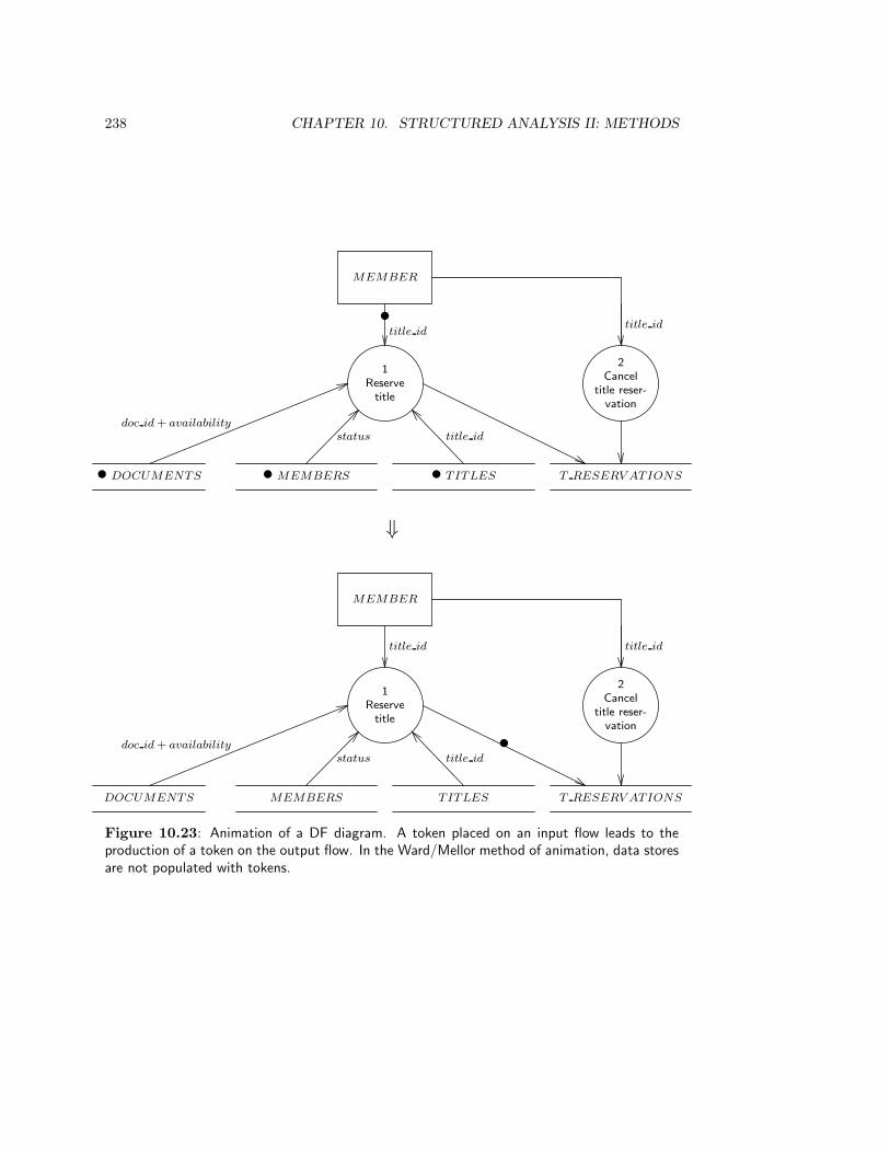
238 CHAPTER 10. STRUCTURED ANALYSIS II: METHODS
1
Reserve
title
MEMBER
•title id
• MEMBERS
status
• DOCUMENTS
doc id + availability
• TITLES
title id
T RESERV ATIONS
2
Cancel
title reser-
vation
title id
1
Reserve
title
MEMBER
title id
MEMBERS
status
DOCUMENTS
doc id + availability
T ITLES
title id
T RESERV ATIONS
•
2
Cancel
title reser-
vation
title id
⇓
Figure 10.23: Animation of a DF diagram. A token placed on an input flow leads to theproduction of a token on the output flow. In the Ward/Mellor method of animation, data storesare not populated with tokens.
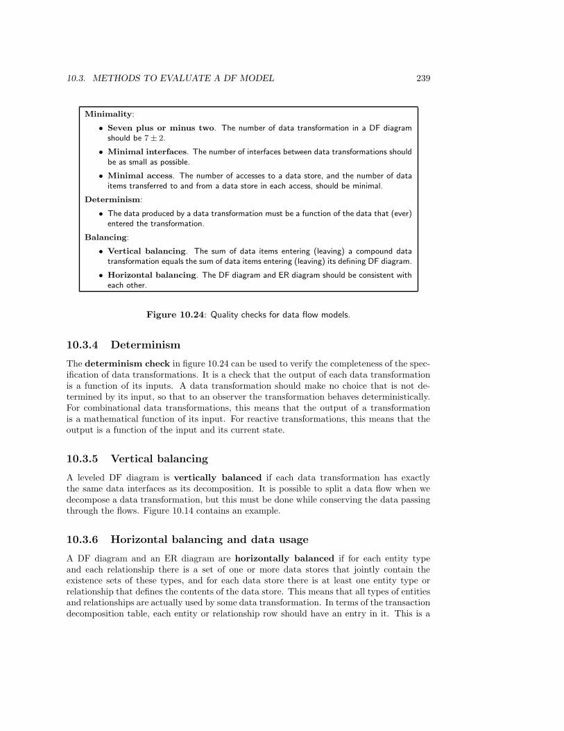
10.3. METHODS TO EVALUATE A DF MODEL 239
Minimality:
• Seven plus or minus two. The number of data transformation in a DF diagramshould be 7 ± 2.
• Minimal interfaces. The number of interfaces between data transformations shouldbe as small as possible.
• Minimal access. The number of accesses to a data store, and the number of dataitems transferred to and from a data store in each access, should be minimal.
Determinism:
• The data produced by a data transformation must be a function of the data that (ever)entered the transformation.
Balancing:
• Vertical balancing. The sum of data items entering (leaving) a compound datatransformation equals the sum of data items entering (leaving) its defining DF diagram.
• Horizontal balancing. The DF diagram and ER diagram should be consistent witheach other.
Figure 10.24: Quality checks for data flow models.
10.3.4 Determinism
The determinism check in figure 10.24 can be used to verify the completeness of the spec-ification of data transformations. It is a check that the output of each data transformationis a function of its inputs. A data transformation should make no choice that is not de-termined by its input, so that to an observer the transformation behaves deterministically.For combinational data transformations, this means that the output of a transformationis a mathematical function of its input. For reactive transformations, this means that theoutput is a function of the input and its current state.
10.3.5 Vertical balancing
A leveled DF diagram is vertically balanced if each data transformation has exactlythe same data interfaces as its decomposition. It is possible to split a data flow when wedecompose a data transformation, but this must be done while conserving the data passingthrough the flows. Figure 10.14 contains an example.
10.3.6 Horizontal balancing and data usage
A DF diagram and an ER diagram are horizontally balanced if for each entity typeand each relationship there is a set of one or more data stores that jointly contain theexistence sets of these types, and for each data store there is at least one entity type orrelationship that defines the contents of the data store. This means that all types of entitiesand relationships are actually used by some data transformation. In terms of the transactiondecomposition table, each entity or relationship row should have an entry in it. This is a
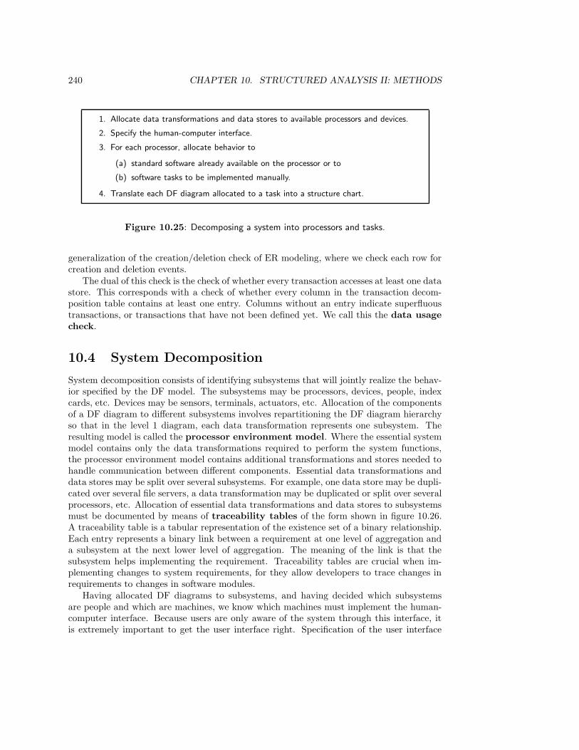
240 CHAPTER 10. STRUCTURED ANALYSIS II: METHODS
1. Allocate data transformations and data stores to available processors and devices.
2. Specify the human-computer interface.
3. For each processor, allocate behavior to
(a) standard software already available on the processor or to
(b) software tasks to be implemented manually.
4. Translate each DF diagram allocated to a task into a structure chart.
Figure 10.25: Decomposing a system into processors and tasks.
generalization of the creation/deletion check of ER modeling, where we check each row forcreation and deletion events.
The dual of this check is the check of whether every transaction accesses at least one datastore. This corresponds with a check of whether every column in the transaction decom-position table contains at least one entry. Columns without an entry indicate superfluoustransactions, or transactions that have not been defined yet. We call this the data usagecheck.
10.4 System Decomposition
System decomposition consists of identifying subsystems that will jointly realize the behav-ior specified by the DF model. The subsystems may be processors, devices, people, indexcards, etc. Devices may be sensors, terminals, actuators, etc. Allocation of the componentsof a DF diagram to different subsystems involves repartitioning the DF diagram hierarchyso that in the level 1 diagram, each data transformation represents one subsystem. Theresulting model is called the processor environment model. Where the essential systemmodel contains only the data transformations required to perform the system functions,the processor environment model contains additional transformations and stores needed tohandle communication between different components. Essential data transformations anddata stores may be split over several subsystems. For example, one data store may be dupli-cated over several file servers, a data transformation may be duplicated or split over severalprocessors, etc. Allocation of essential data transformations and data stores to subsystemsmust be documented by means of traceability tables of the form shown in figure 10.26.A traceability table is a tabular representation of the existence set of a binary relationship.Each entry represents a binary link between a requirement at one level of aggregation anda subsystem at the next lower level of aggregation. The meaning of the link is that thesubsystem helps implementing the requirement. Traceability tables are crucial when im-plementing changes to system requirements, for they allow developers to trace changes inrequirements to changes in software modules.
Having allocated DF diagrams to subsystems, and having decided which subsystemsare people and which are machines, we know which machines must implement the human-computer interface. Because users are only aware of the system through this interface, itis extremely important to get the user interface right. Specification of the user interface

10.5. METHODOLOGICAL ANALYSIS 241
Subsystem 1 Subsystem 2 · · · · · ·
Data transformation 1 X
Data transformation 2 X
Data transformation 3 X X
· · · · · ·
Data store 1 X
Data store 2 X X
Data store 3 X
· · · · · ·
Figure 10.26: Format of traceability tables. A traceability table links elements at one level ofaggregation (vertical dimension) to subsystems at the next lower level of aggregation (horizontaldimension) to which they are allocated.
involves addition of transformations that deal with user dialogues, menu structures, screenforms, report formats, etc.
For each machine, certain software may already be available for many of the tasksspecified by the DF model of that machine. Libraries of reusable software components suchas graphical routines, mathematical libraries, operating system libraries (e.g. routines fordisk access), database management systems, etc. can be used to buy software to performcertain standard tasks. To exploit the availability of this software, the DF diagram for eachmachine is reorganized so that as many transformations as possible correspond to theseready-made software packages. These transformations then need not be implemented byhandcraft but by means of reusable components. The resulting model is called a softwareenvironment model.
The data transformations for which no reusable software is available are now groupedinto tasks, where a task is a sequential process. Tasks are allocated to one machine, whichtreats them as execution units that can be scheduled. Each task is a sequential process thatdoes the work of one or more data transformations. Allocation of data transformationsfrom the processor environment model to tasks in the software environment model must bedocumented by means of additional traceability tables.
Each task can now be designed by drawing a module diagram called a structure chart.This shows the organization of the code for the task into a hierarchical collection of mod-ules, and show the flow of data and control between modules. Task design by means ofstructure charts is traditionally called structured design. Traditional structured develop-ment assumes that all tasks the SuD must be programmed manually and that the hardwareconsists of one processor; in this case, structured design follows structured analysis withoutintermediary decomposition or allocation steps.
10.5 Methodological Analysis
10.5.1 Essential system modeling
Essential system modeling is also called reverse engineering, which is a curious butcorrect term that indicates system modeling. The term reverse engineering connotes the

242 CHAPTER 10. STRUCTURED ANALYSIS II: METHODS
idea of extracting requirements from a current system. These requirements may never havebeen written down, and they are needed if we are to replace a current system with anothersystem, for we must know which essential requirements must be satisfied by the futuresystem. Essential system modeling is a sensible thing to do when we want to reengineera current system, i.e. to reimplement the current functionality with new technology. It isa reassuring activity from a modeling point of view, because there exists a system againstwhich we can verify our model. In addition, if there is a current system, it is important forthe developer of a future system to know what the current system is doing. Some of thefunctions of the current system may be so obviously needed in the opinion of the client,that the developer may never hear that they are needed.
The danger of the essential system modeling process proposed by McMenamin andPalmer is that one gets stuck in what they call the current physical tarpit. The modelercan lose too much time modeling too many details about the current physical system, thatwill be replaced anyway. Current physical system modeling may be useful, but the returnsof this effort diminish quickly as the effort increases.
Current systems modeling is impossible if there is no current system to model. However,even if there is a current system, its functionality may be so inadequate that it is not worththe effort to model it. Approaches like ISAC and Information Engineering are orientedto developing systems with an enhanced functionality compared to the current system.In these approaches, system development is always part of business development, and thefuture information systems are therefore likely to have different functions than the currentsystems have. Thus, the effort spent on current system modeling must be determined bythe balance between the need to get a true model of current functionality and the need toget a model of truly useful future functionality.
In an interesting empirical study of nine developers in three different companies byBansler and Bødker [20], it was found that all interviewed developers did not make acurrent system model but immediately started by making a DF model of the requiredsystem. Bansler and Bødker also report a number of other interesting findings:
• The data flow models built in the investigated projects did not represent the essenceof the required system, but described the required system in physical terms. In otherwords, during requirements engineering, implementation decisions were made.
• One of the implementation decisions made immediately was the determination ofwhich part of the future system would be automated. This agrees with the ISAC,where this choice is made during activity study at the latest, which is before a precisemodel of the required systems is made. DF diagrams are used only to model theautomated parts of the new situation; the manual part was modeled by other means.
• With one exception, the data flow models were not validated by users or domainspecialists. In fact, they were never shown to users or domain specialists, becausein the experience of the interviewed developers, users and domain specialists don’tunderstand data flow models. The domain specialists felt comfortable with plaintext but had a hard time reading (or even looking at) diagrams, so the developersvalidated the diagrams themselves. An interesting exception to this is the case wherethe domain specialists were engineers and technicians, used to constructing technicaldiagrams. These had a hard time reading text but felt comfortable with the diagrams.
10.6. SUMMARY 243
• In one case only, the data flow model was updated to reflect changes to the systemafter it was implemented. In all other cases, changes to the implemented system werenot reflected in the data flow model, so that the model was allowed to become obsoleteduring the system maintenance phase.
10.5.2 Event partitioning and data flow orientation
The method of event partitioning as presented in figure 10.4 starts with identifying the dataflows between the SuD and its external entities, and identifies relevant events later. Thisis the natural thing to do if data flows are visible as paper forms that enter and leave anorganization. It is then easy to first identify these forms, and next identify the events ofreceiving and sending a paper form. It is not the natural thing to do if the environmentconsists of other systems for which a list of input and output events is known. For controlsystems, it is more natural to think in terms of events and responses and worry about thedata flows later. In addition, control system usually must respond to a large number oftemporal events, for which no input data flows exist at all. The order of tasks in figure 10.4should therefore be taken with a grain of salt; what is important is that for each transaction,a DF fragment is built. Each transaction consists of an event and a response, which at therequirements specification level are assumed to occur simultaneously; and each event andeach response consists of zero or more data flows. It is just a matter of convenience whetherwe start with identifying relevant data flows, with identifying relevant events, or identifyingrelevant transactions. Note however that in order to build a functional DF model, we mustat some point identify the relevant transactions. It is therefore always a good strategy totry finding the relevant transactions first, and turn to data flows or events only when it ishard to find the transactions immediately.
10.5.3 Specification of user procedures
Part of the system decomposition task is the determination of the boundary between peopleand machines. Because the specification techniques of DF models are oriented to automatedsystems, a consequence of postponing the choice of human-machine boundary until thedesign task is that the requirements specification represents human work in the same wayas automated work. This totally ignores the important subject of work satisfaction. Peopledo not tend to function very well if all they can do is perform tasks that are prescribed inminispecs down to the smallest details. One way to increase work satisfaction, and thereforehuman productivity, is to fix the human-machine boundary much earlier and specify humanwork by techniques from social psychology. As already remarked in the ISAC methodologicaldiscussion, there is something to say for specifying human work first and specifying machinework later. The study of Bansler and Bødker indicates that this agrees with what happensin practice anyway. One could turn to methods like ETHICS (appendix C) to borrowmethods for the analysis of human work problems and for the specification of human workprocedures.
10.6 Summary
A DF model of a future system can be found by means of essential system modeling, wherewe model the current physical system first, extract the essential model from this, and use

244 CHAPTER 10. STRUCTURED ANALYSIS II: METHODS
this as the basis for the requirements on the future system. Part of the process of finding anessential system model is event partitioning, where we make a list of events to be handled bythe current system, and for each event list the response produced by the system. The list ofevent-response pairs is used to define DF fragments of system activity. Event partitioningcan just as well be used for future system modeling. An alternative to event partitioning isprocess analysis of transactions, which uses the transaction decomposition table to defineDF fragments.
DF models can be evaluated by means of walkthroughs or inspections, in which devel-opers and other relevant people evaluate a model on certain criteria. The model may besimulated and the simulations animated to enhance the understanding the behavior speci-fied by the model. Simulations may be value-based or token-based. Minimality checks of aDF model check whether the number of transformations in a DF diagram is small enoughto be comprehensible, whether the number of interfaces between data transformations isminimal, and whether the data fetched or stored in a data store should be minimal. In thedeterminism check, we verify that each transformation produces output that is a mathe-matical function of the input that ever was received by the transformation. The verticalbalancing check consists of verifying that the data that flow into or out of a transformationequal the data that flow into or out of its decomposition. The horizontal balancing checkverifies that the data stores in a DF diagram correspond to entity or relationship types inthe ER diagram, and that the ER diagram is consistent with the data structure definitionsin the data dictionary. This extends the creation/deletion check of ER modeling. The datausage check verifies whether every system transaction uses some data.
Essential system modeling has the advantage that there is an existing system againstwhich we can verify the model, but it has the danger that we can spend too much effort inmodeling a system that is no longer useful. Empirical research indicates that DF modelsare only used for the automated part of the required system, and that from the start theyrepresent the physical structure of the system. They are not validated with the domainspecialists, they are used for system implementation without going through an intermediatedesign stage, and after implementation they are not updated when the system is maintained.
Structured analysis tends to treat human work in the same way as mechanical work.The decision where to draw the human-machine interface is made only during design, anduntil that time all transformations are specified as if they had to be performed by machine.This is likely to result in user procedures that degrade the quality of work for the systemuser.
10.7 Exercises
1. Why is the Lend document transformation connected to the T RESERV ATIONS
data store with a bidirectional arrow in figure 10.12?
2. Extend the library model with the following functions:
(a) Specify two different Document Lending transactions, one in which the documentis reserved (through a title reservation) and one in which it is not reserved.
(b) After a document return, the administration checks whether there are outstand-ing reservations for this title, and if so, puts the document aside for one week andnotifies the first reserver. If this reserver does not collect the document within

10.8. BIBLIOGRAPHICAL REMARKS 245
one week, his or her reservation is canceled and the next reserver is notified. Ifthere are no more reservers, the document is returned to the store.
3. Make a list of event-response pairs for the circulation administration and indicate foreach pair, with which DF fragment it corresponds.
4. Analyze the method of classical structured development, listed in appendix C, ac-cording to the framework for development methods in figure 3.9. In particular, foreach task in classical structured analysis, indicate whether the task is concerned withbehavior specification at a particular aggregation level, or with system decomposition,and indicate any occurrence of the engineering cycle.
5. Appendix C describes the steps in modern structured development. Analyze thismethod according to the guidelines in exercise 4.
10.8 Bibliographical Remarks
Genealogy. The original 1977 paper by Ross and Schoman [294] is mandatory readingto get the major ideas behind structured analysis. The SADT flavor of structured analysisis elaborated in some later papers by [290, 292] and described in detail by Marca andGowan [210].
In this chapter, we discussed a different flavor of structured analysis, dues to De-Marco [84], V. Weinberg [358], Gane and Sarson [108], and Yourdon and Constantine [378].A milestone in the development of structured analysis is the definition of essential systemmodeling and of event partitioning by McMenamin and Palmer [225] in the mid-1980s. Themethod was further elaborated with real-time extensions, not treated in this chapter, byWard and Mellor [352, 354, 355, 227] and by Hatley and Pirbhai [141].
The transition to structured design is described by Stevens, Myers and Constantine [325],Yourdon and Constantine [378] and by Page-Jones [251]. The definition of a system archi-tecture for real-time systems is treated by Ward and Mellor [352, 354, 355, 227], Hatley andPirbhai [141], and Goldsmith [118].
Rock-Evans [282, 283] gives a comprehensive survey of techniques and heuristics ofDF modeling, called activity modeling by her. The presentation in this chapter is basedprimarily on DeMarco [84], which is still very readable, Goldsmith [118], and McMenaminand Palmer [225].
Seven plus or minus two. The 7 ± 2 check comes from psychological experiments per-formed by Miller [229] in 1956. It is cited by Ross in his initial paper on structured anal-ysis [291] and repeated in probably every text in structured analysis after that, includingthis chapter.
Determinism and data conservation. DeMarco introduces the determinism check un-der the name data conservation check [84, page 109]. By data conservation is meantthat the data transformation does not invent something out of nothing. The data thatleave the transformation is the data that enter it, plus possibly some constant difference.This is a misleading way of stating it, for whatever a data transformation does, it does notconserve all the data that enter it. In fact, reactive data transformations implemented on a

246 CHAPTER 10. STRUCTURED ANALYSIS II: METHODS
finite-state machine can have only a finite memory, so that most data that enter them areeventually destroyed.
Chapter 11
Jackson System Development I:Models
11.1 Introduction
Just like Structured Development, Jackson System Development (JSD) was developed inthe 1970s by lifting the structured approach from the level of programs to the level of soft-ware systems. Despite this common background, JSD differs considerably from structuredanalysis. To understand this difference, we must understand the background of JSD inJackson Structured Programming.
11.1.1 Jackson Structured Programming
Where Structured Analysis has as its background the structured programming school ofHoare and Dijkstra, JSD has a different background, that of Jackson Structured Pro-gramming (JSP). JSP is a method for developing programs whose task is to transforma number of input files into a number of output files. Let us call this class of programsadministrative programs. An example of such an administrative program is a databasequery. For example, a query to the student administration database takes as its input thedata stores of the database and produces as output a printable file that contains a reportabout the contents of the data stores.
The three crucial ideas of JSP with respect to the construction of administrative pro-grams are the following:
1. The structure of the input and output files of administrative programs can alwaysbe described as a structure built from elementary data items, where the structuringoperators are concatenation, choice and iteration.
2. A program can be described as a structure built from elementary programming state-ments, where the structuring operators are concatenation (i.e. sequencing), choiceand iteration.
3. The structure of the program is derivable from the structure of the input and outputfiles.
247
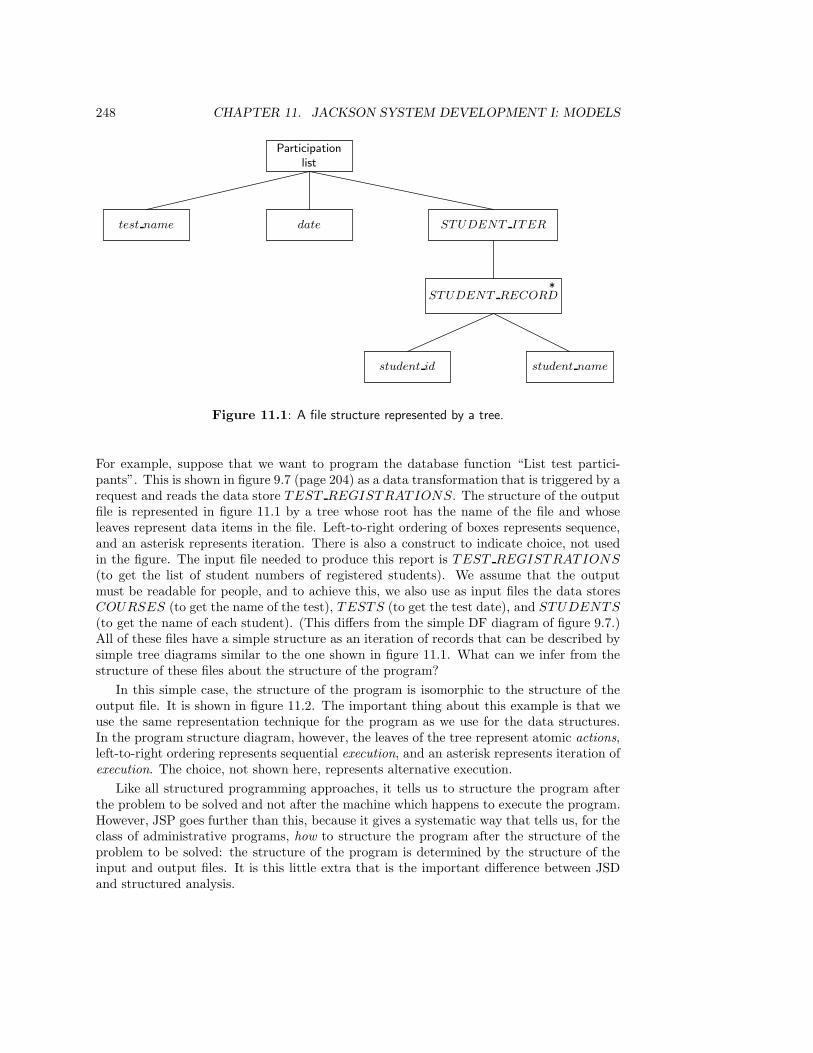
248 CHAPTER 11. JACKSON SYSTEM DEVELOPMENT I: MODELS
Participationlist
datetest name STUDENT ITER
STUDENT RECORD*
student namestudent id
Figure 11.1: A file structure represented by a tree.
For example, suppose that we want to program the database function “List test partici-pants”. This is shown in figure 9.7 (page 204) as a data transformation that is triggered by arequest and reads the data store TEST REGISTRATIONS. The structure of the outputfile is represented in figure 11.1 by a tree whose root has the name of the file and whoseleaves represent data items in the file. Left-to-right ordering of boxes represents sequence,and an asterisk represents iteration. There is also a construct to indicate choice, not usedin the figure. The input file needed to produce this report is TEST REGISTRATIONS
(to get the list of student numbers of registered students). We assume that the outputmust be readable for people, and to achieve this, we also use as input files the data storesCOURSES (to get the name of the test), TESTS (to get the test date), and STUDENTS
(to get the name of each student). (This differs from the simple DF diagram of figure 9.7.)All of these files have a simple structure as an iteration of records that can be described bysimple tree diagrams similar to the one shown in figure 11.1. What can we infer from thestructure of these files about the structure of the program?
In this simple case, the structure of the program is isomorphic to the structure of theoutput file. It is shown in figure 11.2. The important thing about this example is that weuse the same representation technique for the program as we use for the data structures.In the program structure diagram, however, the leaves of the tree represent atomic actions,left-to-right ordering represents sequential execution, and an asterisk represents iteration ofexecution. The choice, not shown here, represents alternative execution.
Like all structured programming approaches, it tells us to structure the program afterthe problem to be solved and not after the machine which happens to execute the program.However, JSP goes further than this, because it gives a systematic way that tells us, for theclass of administrative programs, how to structure the program after the structure of theproblem to be solved: the structure of the program is determined by the structure of theinput and output files. It is this little extra that is the important difference between JSDand structured analysis.
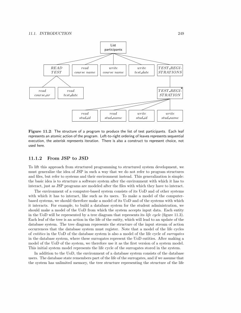
11.1. INTRODUCTION 249
Listparticipants
READ
TEST
read
course name
write
course name
write
test date
TEST REGI-STRATIONS
read
course nr
read
test date
TEST REGI-STRATION
*
read
stud id
read
stud name
write
stud id
write
stud name
Figure 11.2: The structure of a program to produce the list of test participants. Each leafrepresents an atomic action of the program. Left-to-right ordering of leaves represents sequentialexecution, the asterisk represents iteration. There is also a construct to represent choice, notused here.
11.1.2 From JSP to JSD
To lift this approach from structured programming to structured system development, wemust generalize the idea of JSP in such a way that we do not refer to program structuresand files, but refer to systems and their environment instead. This generalization is simple:the basic idea is to structure a software system after the environment with which it has tointeract, just as JSP programs are modeled after the files with which they have to interact.
The environment of a computer-based system consists of its UoD and of other systemswith which it has to interact, like such as its users. To make a model of the computer-based systems, we should therefore make a model of its UoD and of the systems with whichit interacts. For example, to build a database system for the student administration, weshould make a model of the UoD from which the system accepts input data. Each entityin the UoD will be represented by a tree diagram that represents its life cycle (figure 11.3).Each leaf of the tree is an action in the life of the entity, which will lead to an update of thedatabase system. The tree diagram represents the structure of the input stream of actionoccurrences that the database system must register. Note that a model of the life cyclesof entities in the UoD of the database system is also a model of the life cycle of surrogatesin the database system, where these surrogates represent the UoD entities. After making amodel of the UoD of the system, we therefore use it as the first version of a system model.This initial system model represents the life cycle of the surrogates stored in the system.
In addition to the UoD, the environment of a database system consists of the databaseusers. The database state remembers part of the life of the surrogates, and if we assume thatthe system has unlimited memory, the tree structure representing the structure of the life
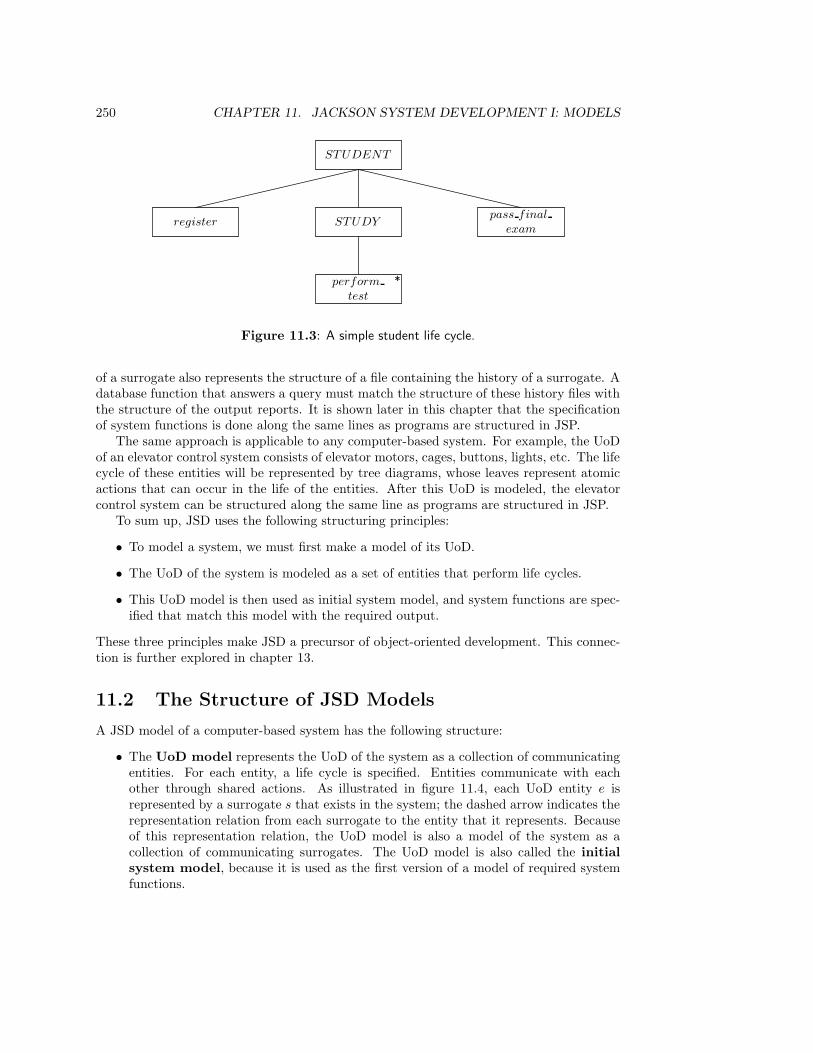
250 CHAPTER 11. JACKSON SYSTEM DEVELOPMENT I: MODELS
STUDENT
STUDYregisterpass final
exam
perform
test
*
Figure 11.3: A simple student life cycle.
of a surrogate also represents the structure of a file containing the history of a surrogate. Adatabase function that answers a query must match the structure of these history files withthe structure of the output reports. It is shown later in this chapter that the specificationof system functions is done along the same lines as programs are structured in JSP.
The same approach is applicable to any computer-based system. For example, the UoDof an elevator control system consists of elevator motors, cages, buttons, lights, etc. The lifecycle of these entities will be represented by tree diagrams, whose leaves represent atomicactions that can occur in the life of the entities. After this UoD is modeled, the elevatorcontrol system can be structured along the same line as programs are structured in JSP.
To sum up, JSD uses the following structuring principles:
• To model a system, we must first make a model of its UoD.
• The UoD of the system is modeled as a set of entities that perform life cycles.
• This UoD model is then used as initial system model, and system functions are spec-ified that match this model with the required output.
These three principles make JSD a precursor of object-oriented development. This connec-tion is further explored in chapter 13.
11.2 The Structure of JSD Models
A JSD model of a computer-based system has the following structure:
• The UoD model represents the UoD of the system as a collection of communicatingentities. For each entity, a life cycle is specified. Entities communicate with eachother through shared actions. As illustrated in figure 11.4, each UoD entity e isrepresented by a surrogate s that exists in the system; the dashed arrow indicates therepresentation relation from each surrogate to the entity that it represents. Becauseof this representation relation, the UoD model is also a model of the system as acollection of communicating surrogates. The UoD model is also called the initialsystem model, because it is used as the first version of a model of required systemfunctions.
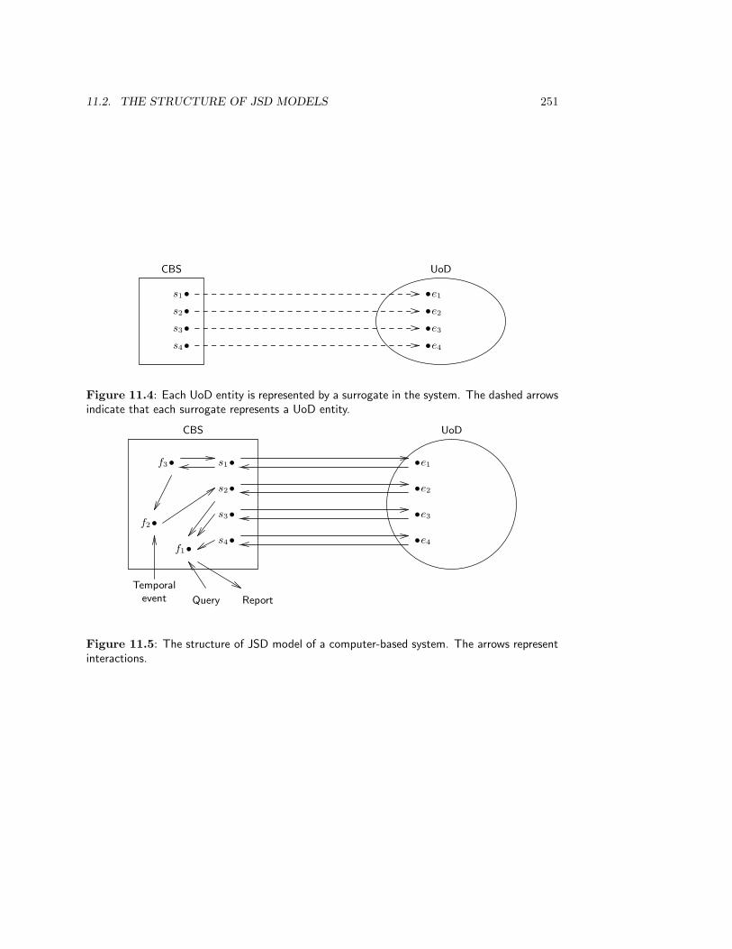
11.2. THE STRUCTURE OF JSD MODELS 251
CBS UoD
•
•
•
•
•
•
•
•
s1 e1
s2 e2
s3 e3
s4 e4
Figure 11.4: Each UoD entity is represented by a surrogate in the system. The dashed arrowsindicate that each surrogate represents a UoD entity.
CBS UoD
•
•
•
•
•
•
•
•
s1 e1
s2 e2
s3 e3
s4 e4
•f3
•f2
•f1
Temporalevent Query Report
Figure 11.5: The structure of JSD model of a computer-based system. The arrows representinteractions.
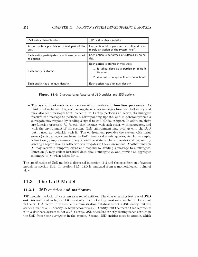
252 CHAPTER 11. JACKSON SYSTEM DEVELOPMENT I: MODELS
JSD entity characteristics JSD action characteristics
An entity is a possible or actual part of theUoD.
Each action takes place in the UoD and is notmerely an action of the system itself.
Each entity participates in a time-ordered setof actions.
Each action is performed or suffered by an en-tity.
Each entity is atomic.
Each action is atomic in two ways:
1. it takes place at a particular point intime and
2. it is not decomposable into subactions.
Each entity has a unique identity. Each action has a unique identity.
Figure 11.6: Characterizing features of JSD entities and JSD actions.
• The system network is a collection of surrogates and function processes. Asillustrated in figure 11.5, each surrogate receives messages from its UoD entity andmay also send messages to it. When a UoD entity performs an action, its surrogatereceives the message to perform a corresponding update, and in control systems asurrogate may respond by sending a signal to its UoD counterpart. In addition, thereare function processes f1, f2, etc. that interact with each other, with surrogates, andwith the environment of the system. This environment may overlap with the UoDbut it need not coincide with it. The environment provides the system with inputevents (which always come from the UoD), temporal events, queries, etc. For example,a function f1 may receive a query about the state of the surrogates and respond bysending a report about a collection of surrogates to the environment. Another functionf2 may receive a temporal event and respond by sending a message to a surrogate.Function f3 may collect historical data about surrogate s1 and provide an aggregatesummary to f2 when asked for it.
The specification of UoD models is discussed in section 11.3 and the specification of systemmodels in section 11.4. In section 11.5, JSD is analyzed from a methodological point ofview.
11.3 The UoD Model
11.3.1 JSD entities and attributes
JSD models the UoD of a system as a set of entities. The characterizing features of JSDentities are listed in figure 11.6. First of all, a JSD entity must exist in the UoD and notin the SuD. A record in the student administration database is not a JSD entity, but thestudent itself is a JSD entity. A bank account is a JSD entity, but the record that representsit in a database system is not a JSD entity. JSD therefore strictly distinguishes entities inthe UoD from their surrogates in the system. Second, JSD entities must be atomic, which

11.3. THE UOD MODEL 253
means that the composition of a committee or of a queue of members who reserved a book isignored. If we want to represent a committee or a queue as JSD entities, we must representthem as atomic entities. Third, they must have a unique identity that is independent fromthe state of the entity and that cannot be changed by any action. This means that if acommittee is represented as a JSD entity, and the committee changes membership, then inJSD this would not lead to a change in identity of the committee. Finally, JSD entities musthave something to do or something must be done to them, or both. A student registers fora test, receives a mark and writes a thesis, a bank account suffers deposit and withdrawalactions.
JSD entities are classified into types such that all entities of one type have a life cyclewith the same structure. If T is the type of e, then e is called an instance of T . Eachentity is an instance of exactly one type. The extension of each JSD entity type is theset of all possible and currently existing instances. In each possible state of the UoD, theexistence set of a JSD entity type is the set of existing instances of the type.
JSD entities can have attributes, which are types of observable properties. For example,name is a type of observable property of a person, hence it is an attribute. An instance ofthis type is the name “John”, which is called an attribute value of name. JSD requireseach entity to have an identifier attribute, which is unique over all possible instances ofa type and which never changes.
11.3.2 Life cycles
JSD actions
A JSD action is an event in which one or more JSD entities participate by suffering orperforming the action. JSD actions have the characteristics listed in figure 11.6. First, aJSD action must occur in the life of an entity in the UoD. Producing a report about testresults or updating a student record are no JSD actions. On the other hand, “Becomestudent” and “lose student registration card” can be modeled as JSD actions. If we candescribe an action without mentioning or presupposing the SuD, then the action is a JSDaction.
Sometimes, UoD actions only have legal validity if they are registered by a databasesystem. For example, a student and a university can enter into an agreement in whichthe university promises to conduct a test and the student promises to perform the test.This event is normally called “registering for a test”, because the agreement is sealed bya registration action. In other words, making the agreement is an action in the UoD thatoccurs synchronously with a database update in which the occurrence of this agreementis registered. Making the agreement is an action in the UoD; registering it in a databasesystem is system action. Because successful occurrence of the registration is a preconditionfor the successful occurrence of the agreement, people describe this agreement as “registeringfor a test”. Because this is the common name for it, I will continue to use it as a name fora UoD action.
We now turn to the other criteria for JSD actions. A UoD action can only be a JSDaction if it occurs in the life of a JSD entity. If we have omitted certain UoD entities fromour model, then all actions in the life of those entities are not modeled as JSD actions, eventhough they occur in the UoD. If we do not model the chairs in the course rooms, thenmoving a chair to another room is not a JSD action.
254 CHAPTER 11. JACKSON SYSTEM DEVELOPMENT I: MODELS
JSD actions must be atomic in two ways:
• An action must occur at a specific point in time. This distinguishes actions fromstates, which persist over a period of time. For example, walking is not a JSD actionbut a state, because it persists over a period of time. To start walking and to stopwalking are JSD actions, though. It does not make sense of JSD actions to ask whenthey began or how long they lasted, for they are considered to be instantaneous.Instead, one can ask how frequently an action occurs.
• An action must not be decomposable into subactions. This distinguishes actionsfrom processes. For example, doing a test is not an atomic action, because it can bedecomposed into at least two subactions, registration for the test and receiving a markfor the test. For the purpose of the student administration, we consider these last twoactions as atomic. Note that this is a choice of abstraction level, since we choose toignore the lower-level process in which test registration is implemented (i.e. requesttest registration, verify existence of test and student, update the test registrationrecord, confirm to the student). JSD actions are transactions of JSD entities, in thesense that we defined transactions in chapter 2.
Finally, a JSD action must have a unique identity. As in the case of JSD entities, this meansit can be given a unique proper name as identifier. For example, in a model of the circulationdesk, there is only one action called borrow. Without unique action identification, we couldnot refer to actions by their name. Note however, that an action is associated with an entitytype. If the borrow action is associated with the type MEMBER, then every MEMBER
instance m can perform an instance of borrow that we will denote with borrow(m), wherem is the identifier of a MEMBER instance. Furthermore, one member can perform thesame action instance borrow(m) any number of times. We write borrow(m)@t for theoccurrence of borrow(m) at time t. To avoid cumbersome expressions, we will say that anentity performs an action rather than that it performs an action instance.
There is a special JSD action called null, which represents non-action. The null actionrepresents the fact that nothing occurs during a tick of the clock. We may explicitly modela null action to indicate that a JSD entity has a choice between doing something and doingnothing, and after either of these cases can continue with other actions. An example willbe given later.
Process structure diagrams
Each entity has a life cycle whose structure can be represented by a process structurediagram (PSD)1. Figure 11.7 shows a simple PSD for an elevator system. A PSD is a treein which the nodes are drawn as rectangles. The root node carries the label of the JSDentity type, which is also used as the name of the life cycle. The following conventions areused to represent the basic structures of sequence, choice and iteration.
• A sequential execution is represented by a sequence of boxes from left to right.
• An iteration is shown as a box with an asterisk in the upper right corner. An iterationmust be the only child of a sequence.
1In JSD, life cycles are called entity structures and process structure diagrams are called entity
structure diagrams instead.

11.3. THE UOD MODEL 255
ELEV ATOR
OPERATE
ITER
start
operation
finish
operation
MOV E
ALT
*
DOWNo
UPo
no bottom
floor
move
downstop
no top
floormove up stop
Attribute declaration:ELEV ATOR(floor : NATURAL)Action definitions:
Action Precondition Effect
start operation floor := 1
no bottom floor floor > 1
move downMovement is only possiblewhen all doors are closed.
floor := floor − 1
stop
no top floor floor < max
move up Movement is only possiblewhen all doors are closed.
floor := floor + 1
finish operation
Figure 11.7: PSD for the life cycle for an elevator. The PSD can be annotated with relevantinformation about action preconditions and action effects. The effect of actions on the statevector of the elevator is indicated by pseudocode attached to the actions. The events floor > 1and floor < max are outcomes of tests on the value of floor.
256 CHAPTER 11. JACKSON SYSTEM DEVELOPMENT I: MODELS
• A choice is shown as a set of children whose upper right corner is marked with a smallcircle. The choice boxes must all be children of one box, which may have an asteriskin it but may not itself be a choice box.
• Parallelism is represented implicitly. Each instance of an entity type executes aninstance of the PSD for that type in parallel with all other entities. In addition,as explained later, we can define several PSDs for one entity, which are executed inparallel.
By labeling the root of the PSD with the name of an entity type, it is shown that the PSDrepresents the structure of the life cycle of all instances of the type. A PSD is instantiatedin the life of a particular entity. Each entity executes an instance of the PSD defined for itstype. The actions in the PSD are local actions of the entity, that can only change the localentity attributes.
A PSD may be annotated with information not representable in the PSD itself, such as adeclaration of the attributes of the entity type, and a specification of the action preconditionsand action effects. A precondition is a condition of the state of the world (not only theentity itself) that, if false, blocks the occurrence of the action. The effect of an action isspecified by listing the changes of the local state of the entity that occur during the action.The local state of the entity is called the state vector of the entity in JSD and consists ofthe values of all attributes, including the value of a special attribute, called the life cycleindicator (lci). This indicates the position of the entity in its life cycle2. The effect of anaction on the life cycle indicator is not specified in the annotation of the PSD, because it isalready specified by the PSD itself.
At each moment, the entity is either waiting to perform or suffer its first action (i.e.it is waiting to be created) or it has a history that ends with the most recent action thatoccurred in its life. These states can be identified by adding leaves to the PSD as illustratedin figure 11.8. We omit this numbering from PSDs and assume that for each PSD thereis an agreed labeling system, that defines the meaning of the values of lci in terms of thePSD. The state vector of the elevator in figure 11.7 has the form
〈floor : m, load : n, lci : p〉.
For example, the occurrence of a stop action in figure 11.7 would increase lci by 1.
Premature termination
Often, an entity life cycle can be terminated by the occurrence of a certain action. Thisaction can occur at any moment in the life of the entity, and when it occurs, it leads to awind-up process, after which the life of the entity terminates. This is called prematuretermination in JSD. Premature termination is represented by indicating points in thelife of an entity at which premature termination can occur, and specifying what happensduring termination in a separate part of the PSD. Normal life is always represented by abranch that describes a process called POSIT (figure 11.9). At the start of the life of theentity, it is not known whether a normal or a prematurely terminated life is started, and theassumption is made (it is posited) that a normal life is followed. There is a second branch
2In JSD, lci is called a text pointer, because it points to a position in the program text associated with
a life cycle.
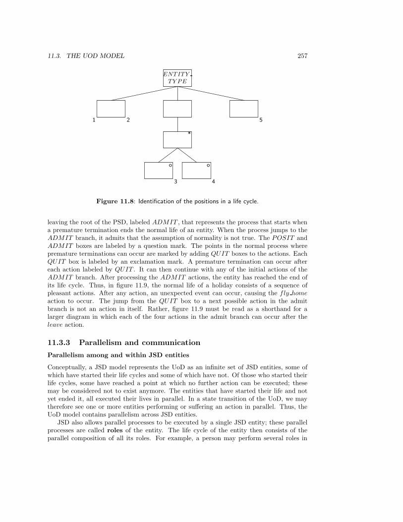
11.3. THE UOD MODEL 257
ENTITY
TY PE
*
o o
1 2
3 4
5
Figure 11.8: Identification of the positions in a life cycle.
leaving the root of the PSD, labeled ADMIT , that represents the process that starts whena premature termination ends the normal life of an entity. When the process jumps to theADMIT branch, it admits that the assumption of normality is not true. The POSIT andADMIT boxes are labeled by a question mark. The points in the normal process wherepremature terminations can occur are marked by adding QUIT boxes to the actions. EachQUIT box is labeled by an exclamation mark. A premature termination can occur aftereach action labeled by QUIT . It can then continue with any of the initial actions of theADMIT branch. After processing the ADMIT actions, the entity has reached the end ofits life cycle. Thus, in figure 11.9, the normal life of a holiday consists of a sequence ofpleasant actions. After any action, an unexpected event can occur, causing the fly home
action to occur. The jump from the QUIT box to a next possible action in the admitbranch is not an action in itself. Rather, figure 11.9 must be read as a shorthand for alarger diagram in which each of the four actions in the admit branch can occur after theleave action.
11.3.3 Parallelism and communication
Parallelism among and within JSD entities
Conceptually, a JSD model represents the UoD as an infinite set of JSD entities, some ofwhich have started their life cycles and some of which have not. Of those who started theirlife cycles, some have reached a point at which no further action can be executed; thesemay be considered not to exist anymore. The entities that have started their life and notyet ended it, all executed their lives in parallel. In a state transition of the UoD, we maytherefore see one or more entities performing or suffering an action in parallel. Thus, theUoD model contains parallelism across JSD entities.
JSD also allows parallel processes to be executed by a single JSD entity; these parallelprocesses are called roles of the entity. The life cycle of the entity then consists of theparallel composition of all its roles. For example, a person may perform several roles in
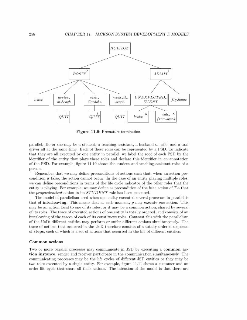
258 CHAPTER 11. JACKSON SYSTEM DEVELOPMENT I: MODELS
HOLIDAY
POSIT?
ADMIT?
leavearrive
at beach
visit
Cordoba
relax at
beach
QUIT QUIT QUIT! ! !
UNEXPECTED
EV ENTfly home
brokeo call
from work
o
Figure 11.9: Premature termination.
parallel. He or she may be a student, a teaching assistant, a husband or wife, and a taxidriver all at the same time. Each of these roles can be represented by a PSD. To indicatethat they are all executed by one entity in parallel, we label the root of each PSD by theidentifier of the entity that plays these roles and declare this identifier in an annotationof the PSD. For example, figure 11.10 shows the student and teaching assistant roles of aperson.
Remember that we may define preconditions of actions such that, when an action pre-condition is false, the action cannot occur. In the case of an entity playing multiple roles,we can define preconditions in terms of the life cycle indicator of the other roles that theentity is playing. For example, we may define as precondition of the hire action of TA thatthe propaedeutical action in its STUDENT role has been executed.
The model of parallelism used when one entity executed several processes in parallel isthat of interleaving. This means that at each moment, p may execute one action. Thismay be an action local to one of its roles, or it may be a common action, shared by severalof its roles. The trace of executed actions of one entity is totally ordered, and consists of aninterleaving of the traces of each of its constituent roles. Contrast this with the parallelismof the UoD: different entities may perform or suffer different actions simultaneously. Thetrace of actions that occurred in the UoD therefore consists of a totally ordered sequenceof steps, each of which is a set of actions that occurred in the life of different entities.
Common actions
Two or more parallel processes may communicate in JSD by executing a common ac-tion instance. sender and receiver participate in the communication simultaneously. Thecommunicating processes may be the life cycles of different JSD entities or they may betwo roles executed by a single entity. For example, figure 11.11 shows a customer and anorder life cycle that share all their actions. The intention of the model is that there are
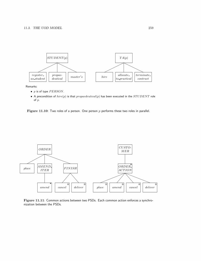
11.3. THE UOD MODEL 259
STUDENT (p)
propae-deutical
register
as studentmaster′s
TA(p)
allocate
to practicalhire
terminate
contract
Remarks:
• p is of type PERSON .
• A precondition of hire(p) is that propaedeutical(p) has been executed in the STUDENT roleof p.
Figure 11.10: Two roles of a person. One person p performs these two roles in parallel.
ORDER
AMEND
ITERplace FINISH
amend*
cancelo
delivero
CUSTO-MER
ORDER
ACTION
*
placeo
amendo
cancelo
delivero
Figure 11.11: Common actions between two PSDs. Each common action enforces a synchro-nization between the PSDs.
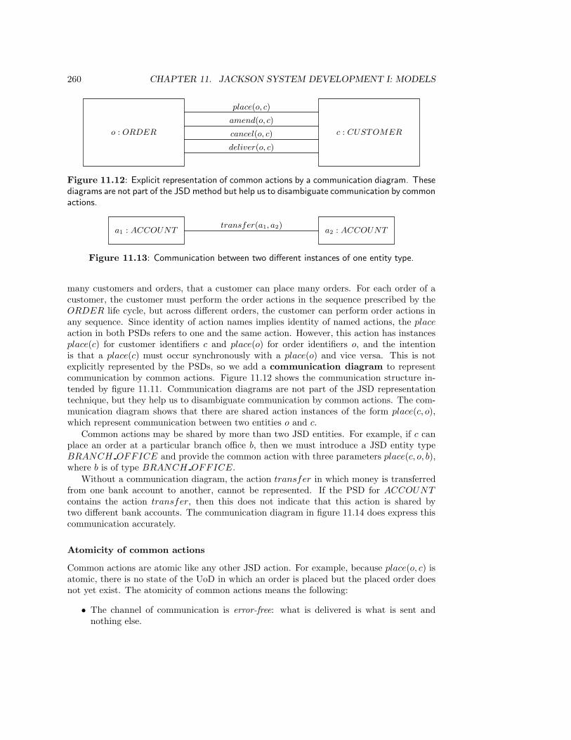
260 CHAPTER 11. JACKSON SYSTEM DEVELOPMENT I: MODELS
o : ORDER c : CUSTOMER
deliver(o, c)
cancel(o, c)
amend(o, c)
place(o, c)
Figure 11.12: Explicit representation of common actions by a communication diagram. Thesediagrams are not part of the JSD method but help us to disambiguate communication by commonactions.
a1 : ACCOUNT a2 : ACCOUNTtransfer(a1, a2)
Figure 11.13: Communication between two different instances of one entity type.
many customers and orders, that a customer can place many orders. For each order of acustomer, the customer must perform the order actions in the sequence prescribed by theORDER life cycle, but across different orders, the customer can perform order actions inany sequence. Since identity of action names implies identity of named actions, the place
action in both PSDs refers to one and the same action. However, this action has instancesplace(c) for customer identifiers c and place(o) for order identifiers o, and the intentionis that a place(c) must occur synchronously with a place(o) and vice versa. This is notexplicitly represented by the PSDs, so we add a communication diagram to representcommunication by common actions. Figure 11.12 shows the communication structure in-tended by figure 11.11. Communication diagrams are not part of the JSD representationtechnique, but they help us to disambiguate communication by common actions. The com-munication diagram shows that there are shared action instances of the form place(c, o),which represent communication between two entities o and c.
Common actions may be shared by more than two JSD entities. For example, if c canplace an order at a particular branch office b, then we must introduce a JSD entity typeBRANCH OFFICE and provide the common action with three parameters place(c, o, b),where b is of type BRANCH OFFICE.
Without a communication diagram, the action transfer in which money is transferredfrom one bank account to another, cannot be represented. If the PSD for ACCOUNT
contains the action transfer, then this does not indicate that this action is shared bytwo different bank accounts. The communication diagram in figure 11.14 does express thiscommunication accurately.
Atomicity of common actions
Common actions are atomic like any other JSD action. For example, because place(o, c) isatomic, there is no state of the UoD in which an order is placed but the placed order doesnot yet exist. The atomicity of common actions means the following:
• The channel of communication is error-free: what is delivered is what is sent andnothing else.

11.4. THE SYSTEM MODEL 261
s : SELLERm : MAIL
SY STEMb : BUY ER
send item(s,m) deliver
item(m, b)
s : SELLER b : BUY ERtransfer item(s, b)
Figure 11.14: The atomicity of a common action can be resolved into an asynchronouscommunication if we choose a lower level of abstraction.
• The communication is certain: messages are not lost nor delivered at the wrongaddress.
• Communication is synchronous: The delay between sending and delivery is not mod-eled.
If we cannot make these assumptions about a communication, then this communicationshould not be modeled by a common action. Instead, we should then explicitly modelthe communication channel as a JSD entity and model communication of the sender andreceiver with the channel as common actions. Errors, incorrect delivery and delay can thenbe modeled explicitly in the life cycle of the communication channel. For example, the upperpart of figure 11.14 represents order delivery as a synchronous communication. This meansthat we ignore the possibility of garbling the contents of the communication, of deliveringthe item at the wrong address, and the time it takes to get the messages from sender toreceiver. If we cannot or will not ignore one of these aspects, then we should model thecommunication channel as a JSD entity, as shown in the lower half of the figure. The lifecycle for this communication channel can then be used to model unreliable asynchronouscommunication with the possibility of loss and errors.
11.4 The System Model
The UoD model represents the UoD as a collection of communicating entities. Let us callthis model the UoD network. We represent this network by means of communicationdiagrams (not part of JSD) and PSDs. This network is now used as the initial versionof the system model. The type instances are now surrogates for UoD entities and theactions are now updates of the state of surrogates, that correspond to UoD actions. Theinitial model is extended with function processes so that it becomes a system network.The system network is more complex than the UoD network, because it contains functionprocesses in addition to surrogates. Moreover, as we shall see below, there are four differentcommunication mechanisms in the system network.
11.4.1 Process communication in the system network
A communication between two nodes in the system network is called a connection in JSD.The simplest process connection in the system network is communication between surro-gates through shared actions. There are three other kinds of process connections in the sys-
262 CHAPTER 11. JACKSON SYSTEM DEVELOPMENT I: MODELS
tem network: data stream connection, state vector connection, and controlled data streamconnection.
Data stream connections
A data stream connection between two nodes in the system network is a first-in first-out queue to which one node can add data and from which the other can remove data.Communication through a data stream is asynchronous, for the sender can continue aftersending a message, even if the receiver has not yet received the message. Figure 11.15shows a data stream connection D between account instances and instances of the functionACCT HISTORY . The task of ACCT HISTORY is to give a historical overview ofupdates to an account. The structure of the two communicating processes in figure 11.15is shown in figure 11.16. The following features should be noted.
• When two processes communicate through a data stream D, the sender containsactions add 〈record〉 to D and the receiver contains actions remove 〈record〉 from D,where 〈record〉 is a brief indication of the data added to and removed from D. Sucha specification should be precise enough for a programmer to write a program thatimplements the function.
• The structure of the ACCT HISTORY process mirrors the structure of the report tobe produced. The ACCT HISTORY process is constructed according to the struc-tured programming principles of JSP explained in section 11.1. ACCT HISTORY isin this example a simple formatting function: upon request, it empties D and printsthe data that it removes from D. More complex functions can also be specified, thatmanipulate the data before a report is produced. These more complex functions canbe specified using the principles of JSP. Because we do not want to elaborate uponthese principles, we only give examples of very simple function processes.
• ACCT HISTORY is a short-running function process, which is a process that“exists” during one atomic system transaction only. In the system state before thetransaction starts, the short-running function does not exist, and in the state afterthe transaction is finished, the short-running function does not exist either.
• Data stream connections have cardinalities. The default cardinality is 1 on both sides.The default cardinalities in figure 11.15 mean that one instance of ACCT HISTORY
reads a data stream filled by one existing ACCOUNT instance, and that one existingACCOUNT instance sends data to a data stream read by many ACCT HISTORY
instances. As many ACCT HISTORY instances are instantiated as queries are askedabout account histories.
A long-running function process is a function process that exists for longer than a sin-gle transaction. Long-running function processes wait during most of their life for eventsto happen, and when these occur they produce a response in a single transaction. TheACCT HISTORY function can be transformed into a long-running function process byembedding it into an iteration over the report production process. As a long-running func-tion, an ACCT HISTORY instance spends most of its life waiting for a query record toarrive. When such a record arrives, it produces a report in what is conceptually an atomictransaction, and waits for the next query to arrive. The connection cardinality would then

11.4. THE SYSTEM MODEL 263
ACCOUNT D ACCT HISTORY≥ 0
historical
query
history
report
Figure 11.15: System network containing a data stream connection.
ACCOUNT
open LIFE close
TRANSFER*
DEPOSIT WITHDRAWo o
deposit
add
deposit
to D
withdraw
add
withdraw
to D
ACCT
HISTORY
remove
query from
historical
query
PRODUCE
REPORT
REPORT
LINE
*
remove
action
from D
add action to
history
report
Figure 11.16: PSDs for ACCOUNT and ACCT HISTORY , remove and add actionsembedded.
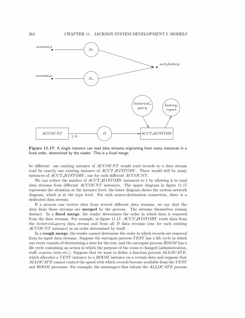
264 CHAPTER 11. JACKSON SYSTEM DEVELOPMENT I: MODELS
ACCOUNT D ACCT HISTORY≥ 0
historical
queryhistory
report
• Dn
• D1
•
account n
account 1
acct history
Figure 11.17: A single instance can read data streams originating from many instances in afixed order, determined by the reader. This is a fixed merge.
be different: one existing instance of ACCOUNT would send records to a data streamread by exactly one existing instance of ACCT HISTORY . There would still be manyinstances of ACCT HISTORY , one for each different ACCOUNT .
We can reduce the number of ACCT HISTORY instances to 1 by allowing it to readdata streams from different ACCOUNT instances. The upper diagram in figure 11.17represents the situation at the instance level, the lower diagram shows the system networkdiagram, which is at the type level. For each source-destination connection, there is adedicated data stream.
If a process can receive data from several different data streams, we say that thedata from these streams are merged by the process. The streams themselves remaindistinct. In a fixed merge, the reader determines the order in which data is removedfrom the data streams. For example, in figure 11.17, ACCT HISTORY reads data fromthe historical query data stream and from all D data streams (one for each existingACCOUNT instance) in an order determined by itself.
In a rough merge, the reader cannot determine the order in which records are removedfrom its input data streams. Suppose the surrogate process TEST has a life cycle in whichone event consists of determining a date for the test, and the surrogate process ROOM has alife cycle containing an action in which the purpose of the room is changed (administration,staff, courses, tests etc.). Suppose that we want to define a function process ALLOCATE,which allocates a TEST instance to a ROOM instance on a certain data and suppose thatALLOCATE cannot control the speed with which records become available from the TEST
and ROOM processes. For example, the messengers that inform the ALLOCATE process
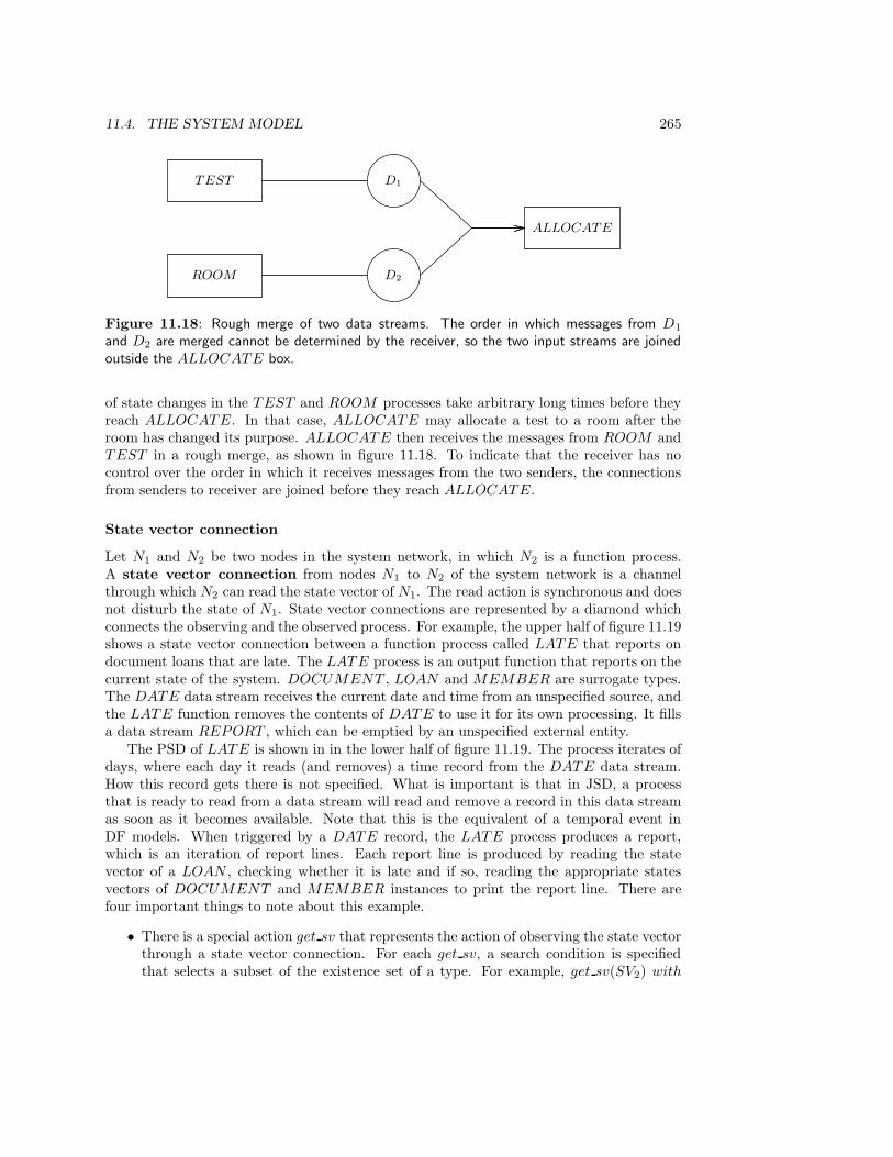
11.4. THE SYSTEM MODEL 265
TEST D1
ROOM D2
ALLOCATE
Figure 11.18: Rough merge of two data streams. The order in which messages from D1
and D2 are merged cannot be determined by the receiver, so the two input streams are joinedoutside the ALLOCATE box.
of state changes in the TEST and ROOM processes take arbitrary long times before theyreach ALLOCATE. In that case, ALLOCATE may allocate a test to a room after theroom has changed its purpose. ALLOCATE then receives the messages from ROOM andTEST in a rough merge, as shown in figure 11.18. To indicate that the receiver has nocontrol over the order in which it receives messages from the two senders, the connectionsfrom senders to receiver are joined before they reach ALLOCATE.
State vector connection
Let N1 and N2 be two nodes in the system network, in which N2 is a function process.A state vector connection from nodes N1 to N2 of the system network is a channelthrough which N2 can read the state vector of N1. The read action is synchronous and doesnot disturb the state of N1. State vector connections are represented by a diamond whichconnects the observing and the observed process. For example, the upper half of figure 11.19shows a state vector connection between a function process called LATE that reports ondocument loans that are late. The LATE process is an output function that reports on thecurrent state of the system. DOCUMENT , LOAN and MEMBER are surrogate types.The DATE data stream receives the current date and time from an unspecified source, andthe LATE function removes the contents of DATE to use it for its own processing. It fillsa data stream REPORT , which can be emptied by an unspecified external entity.
The PSD of LATE is shown in in the lower half of figure 11.19. The process iterates ofdays, where each day it reads (and removes) a time record from the DATE data stream.How this record gets there is not specified. What is important is that in JSD, a processthat is ready to read from a data stream will read and remove a record in this data streamas soon as it becomes available. Note that this is the equivalent of a temporal event inDF models. When triggered by a DATE record, the LATE process produces a report,which is an iteration of report lines. Each report line is produced by reading the statevector of a LOAN , checking whether it is late and if so, reading the appropriate statesvectors of DOCUMENT and MEMBER instances to print the report line. There arefour important things to note about this example.
• There is a special action get sv that represents the action of observing the state vectorthrough a state vector connection. For each get sv, a search condition is specifiedthat selects a subset of the existence set of a type. For example, get sv(SV2) with

266 CHAPTER 11. JACKSON SYSTEM DEVELOPMENT I: MODELS
DOCUMENT
LOAN
MEMBER
SV1
SV2
SV3
LATE
≥ 0
≥ 0
≥ 0
DATE
REPORT
LATE
DAY*
remove day
from DATEREPORT LINE
*
get sv(SV2) with
return date < todayget sv(SV1) get sv(SV3)
add late LOAN
record to REPORT
Figure 11.19: System network and PSD for the LATE function process.

11.4. THE SYSTEM MODEL 267
return date < today selects the existing LOAN instances that are late. get sv yieldsthe entire state vector, i.e. all attributes of the observed process are visible to theobserver. This data is available to the subsequent actions in the life of the observer.
• The structure of the LATE process mirrors the structure of the report to be produced.Again, the function process is constructed according to the structured programmingprinciples of JSP explained in section 11.1. As pointed out before, we do not want totreat these principles here and our function processes are therefore trivial.
• LATE is a long-running function process, which waits most of its time on a temporalevent (the arrival of a date) and then reponds in a single, atomic transaction.
• State vector connections have cardinalities, and the default cardinality is 1 on bothsides. The cardinalities in figure 11.19 mean that one existing instance of LATE mayread the state vector of many instances of DOCUMENT , LOAN and MEMBER,and that each existing instance of DOCUMENT , LOAN and MEMBER is readby exactly one existing instance of LATE.
The LATE function can be transformed into a short-running function process by removingthe DAY iteration and by changing the cardinalities in the system network so that eachexisting instance of DOCUMENT , LOAN and MEMBER is read by arbitrarily manyinstances of LATE.
Controlled data stream connection
A controlled data stream connection is a connection over which one instance observesthe state of the other and, depending on the observed state, performs an action on theobserved process. The observation and action form one atomic transaction. Communicationthrough a controlled data stream is therefore synchronous. The observation is done bymeans of a get sv action and the action is performed by means of an add 〈record〉 to
data stream action. Thus, a controlled data stream connection combines the behavior ofa state vector and a data stream connection. In figure 11.20, a BLOCK function processmonitors the state of the existence set of ACCOUNT surrogates. It also receives all ticksof the clock, as sent to it by the DATE data stream. Each midnight, the BLOCK processbecomes active and scans the existing accounts on the presence of the update conditionbalance(a) < −200. When the condition is satisfied by an account a, the action block(a)is sent to the account. Testing the condition on a and performing the action on a togetheris one atomic action that cannot be interrupted. If we were not to require this atomicity,then it would be possible that the condition that justifies the block action would be undonebefore the action is performed. Note that the add block(a) to CD action is not an additionto a queue, as it would be in the case of a data stream connection. The record written toCD is an action that is executed immediately by the receiver.
11.4.2 The specification of function processes
Input functions
An input function is a process that accepts messages from the environment of the SuD,filters out incorrect messages and sends the remaining ones to the appropriate processes
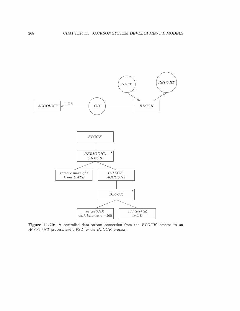
268 CHAPTER 11. JACKSON SYSTEM DEVELOPMENT I: MODELS
ACCOUNT CDn ≥ 0
BLOCK
DATEREPORT
BLOCK
PERIODIC
CHECK
*
remove midnight
from DATE
CHECK
ACCOUNT
BLOCK*
get sv(CD)with balance < −200
add block(a)to CD
Figure 11.20: A controlled data stream connection from the BLOCK process to anACCOUNT process, and a PSD for the BLOCK process.
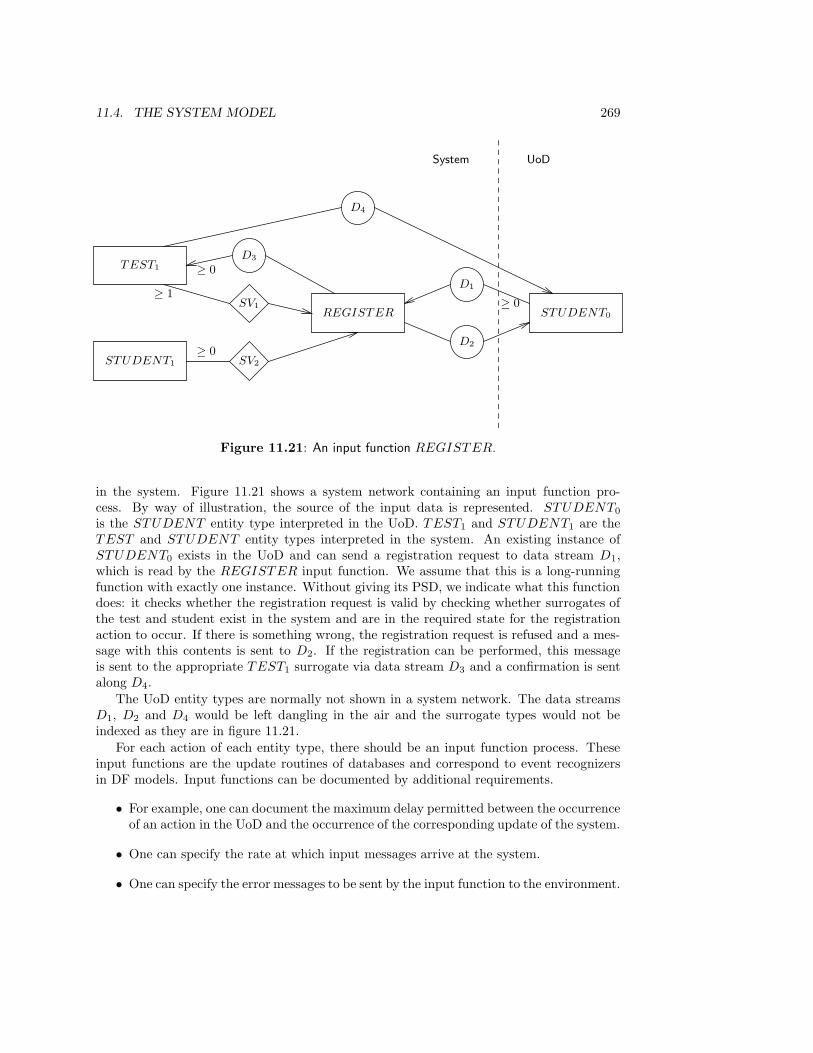
11.4. THE SYSTEM MODEL 269
TEST1 ≥ 0
≥ 1
D3
SV1
STUDENT1
≥ 0SV2
REGISTER STUDENT0
≥ 0
D2
D1
D4
System UoD
Figure 11.21: An input function REGISTER.
in the system. Figure 11.21 shows a system network containing an input function pro-cess. By way of illustration, the source of the input data is represented. STUDENT0
is the STUDENT entity type interpreted in the UoD. TEST1 and STUDENT1 are theTEST and STUDENT entity types interpreted in the system. An existing instance ofSTUDENT0 exists in the UoD and can send a registration request to data stream D1,which is read by the REGISTER input function. We assume that this is a long-runningfunction with exactly one instance. Without giving its PSD, we indicate what this functiondoes: it checks whether the registration request is valid by checking whether surrogates ofthe test and student exist in the system and are in the required state for the registrationaction to occur. If there is something wrong, the registration request is refused and a mes-sage with this contents is sent to D2. If the registration can be performed, this messageis sent to the appropriate TEST1 surrogate via data stream D3 and a confirmation is sentalong D4.
The UoD entity types are normally not shown in a system network. The data streamsD1, D2 and D4 would be left dangling in the air and the surrogate types would not beindexed as they are in figure 11.21.
For each action of each entity type, there should be an input function process. Theseinput functions are the update routines of databases and correspond to event recognizersin DF models. Input functions can be documented by additional requirements.
• For example, one can document the maximum delay permitted between the occurrenceof an action in the UoD and the occurrence of the corresponding update of the system.
• One can specify the rate at which input messages arrive at the system.
• One can specify the error messages to be sent by the input function to the environment.
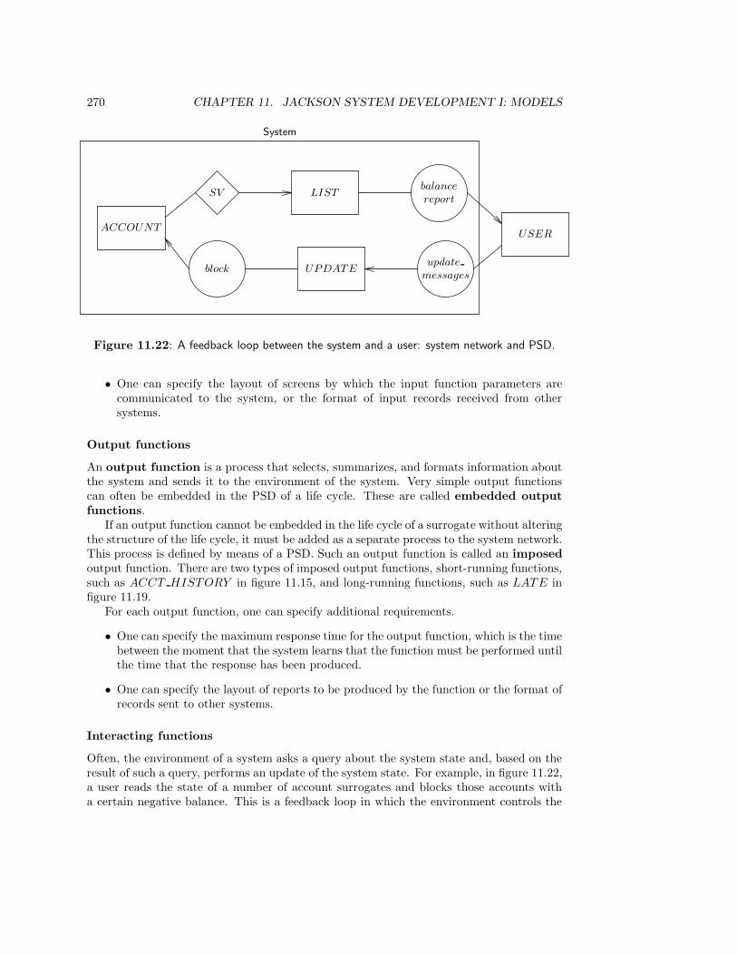
270 CHAPTER 11. JACKSON SYSTEM DEVELOPMENT I: MODELS
ACCOUNT
SV LIST
block
balance
report
USER
UPDATEupdate
messages
System
Figure 11.22: A feedback loop between the system and a user: system network and PSD.
• One can specify the layout of screens by which the input function parameters arecommunicated to the system, or the format of input records received from othersystems.
Output functions
An output function is a process that selects, summarizes, and formats information aboutthe system and sends it to the environment of the system. Very simple output functionscan often be embedded in the PSD of a life cycle. These are called embedded outputfunctions.
If an output function cannot be embedded in the life cycle of a surrogate without alteringthe structure of the life cycle, it must be added as a separate process to the system network.This process is defined by means of a PSD. Such an output function is called an imposedoutput function. There are two types of imposed output functions, short-running functions,such as ACCT HISTORY in figure 11.15, and long-running functions, such as LATE infigure 11.19.
For each output function, one can specify additional requirements.
• One can specify the maximum response time for the output function, which is the timebetween the moment that the system learns that the function must be performed untilthe time that the response has been produced.
• One can specify the layout of reports to be produced by the function or the format ofrecords sent to other systems.
Interacting functions
Often, the environment of a system asks a query about the system state and, based on theresult of such a query, performs an update of the system state. For example, in figure 11.22,a user reads the state of a number of account surrogates and blocks those accounts witha certain negative balance. This is a feedback loop in which the environment controls the
11.5. METHODOLOGICAL ANALYSIS 271
system based on the state of the system and a norm that this state must fulfill. Such afeedback loop is called an interacting function. We can specify this function in JSDby means of a controlled data stream connection as shown in figure 11.20. The BLOCK
function process in figure 11.20 performs the task of the user in figure 11.22.
11.5 Methodological Analysis
11.5.1 The place of JSD models in the behavior specification frame-work
The behavior specification framework of chapter 4 (page 75) distinguishes UoD models fromsystem models. We defer an analysis of UoD models to chapter 13 and restrict ourselveshere to a comparison of system behavior specifications, shown in figure 11.23. When thesystem is ready to engage in a transaction with the environment, the state of a system isrepresented in JSD by
• the set of existing surrogates and their states,
• the set of existing long-running function processes and their states, and
• the contents of the data streams.
Between transactions, data streams may be empty. The system state may be changed bysystem transactions. JSD does not recognize relationships and models these in the sameway as other surrogates for UoD entities. System dynamics is represented in JSD by meansof system transactions of the following three kinds;
• updates to surrogates (input functions),
• responses to system inputs (output functions),
• conditional system updates (interacting functions).
11.5.2 Transactions
Transactions are represented as follows in JSD.
• In the UoD model, a transaction in which a surrogate is updated corresponds to anoccurrence of an action instance a(e), where a is an action and e a UoD entity. Theaction is a leaf in the PSD for the entity type of e. The entire PSD represents theentire life of entities; the leaves of the PSD correspond to system transactions, whichrepresent actions in the life of UoD entities.
• In a model of the SuD, a transaction corresponds to a system function (input, outputor interacting) specified by a PSD. The transaction effects and preconditions arespecified as part of the PSD in the form of actions performed during the transactionand as annotations of PSDs that specify the meaning of actions.
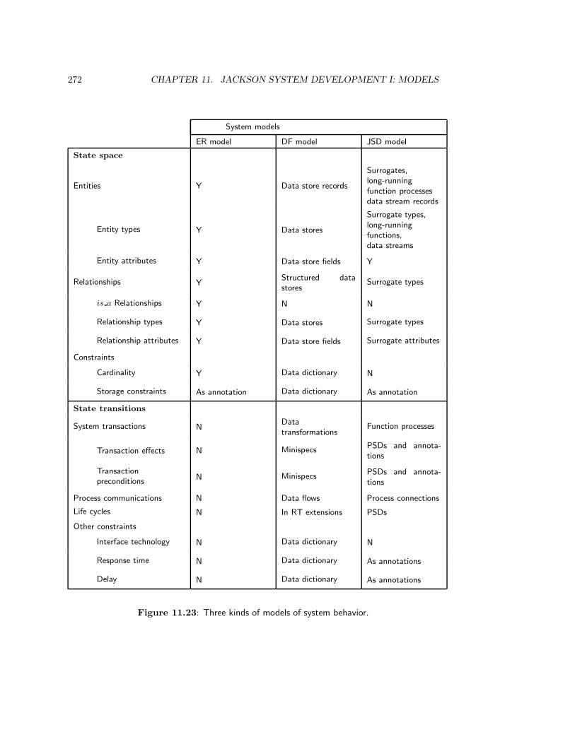
272 CHAPTER 11. JACKSON SYSTEM DEVELOPMENT I: MODELS
System models
ER model DF model JSD model
State space
Entities Y Data store records
Surrogates,long-runningfunction processesdata stream records
Entity types Y Data stores
Surrogate types,long-runningfunctions,data streams
Entity attributes Y Data store fields Y
Relationships YStructured datastores
Surrogate types
is a Relationships Y N N
Relationship types Y Data stores Surrogate types
Relationship attributes Y Data store fields Surrogate attributes
Constraints
Cardinality Y Data dictionary N
Storage constraints As annotation Data dictionary As annotation
State transitions
System transactions NDatatransformations
Function processes
Transaction effects N MinispecsPSDs and annota-tions
Transactionpreconditions
N MinispecsPSDs and annota-tions
Process communications N Data flows Process connections
Life cycles N In RT extensions PSDs
Other constraints
Interface technology N Data dictionary N
Response time N Data dictionary As annotations
Delay N Data dictionary As annotations
Figure 11.23: Three kinds of models of system behavior.

11.5. METHODOLOGICAL ANALYSIS 273
t1 t2 t3 t4 t5 t6 · · ·E1
E2
· · · · · ·D1
D2
Figure 11.24: Transaction decomposition in JSD. Each transaction is an atomic system func-tion. The state of the system between transactions is stored in entities Ei and data streamsDi.
• More precisely, a transaction corresponding to a short-running function is specified bya PSD. The entire PSD represents one system transaction and is therefore atomic. Thesystem is ready to accept new input when the PSD execution is ready. Intermediarystates of the PSD are not observable to the environment.
• A transaction corresponding to one iteration through a long-running function is rep-resented by a subtree of a PSD, which again must be treated as atomic.
The difference can be represented graphically by returning to the transaction decompositiontable (figure 11.24). In JSD, the horizontal dimension of the table corresponds to the threekinds of system functions: input, output and interacting. Each transaction is an atomicsystem function. The vertical dimension represents all JSD entity types and the contents ofthe data streams between transactions. For an input function, each column represents thesurrogates that must be updated; this represents a common action between UoD entities.For an output function, each column represents the data accesses performed to produce theoutput. For an interacting function, each column represents the surrogates whose state isread and the surrogates whose state is updated by the function.
11.5.3 Function specification
Using PSDs to represent entity life cycles as well as system functions is confusing, becausethe level of granularity is different in both cases. In addition, using PSD for a systemfunction is one possible way to program this function, and this is a remnant of JSP. Itis as if we would prescribe using PSDs for each minispec in DF models. This has thenegative consequence that a requirements specification constrains the implementation ofsystem functions unnecessarily. A model of required system functions should specify thisfunction abstractly, without prescribing one particular implementation. One possible way todo this is to specify output functions declaratively in terms of pre- and postconditions to berealized by an implementation of this function. This would leave open whether the functionwould be implemented as a structured program, as in JSD, or as a relational calculusquery expression that operates on sets of records, or by other means. One implementationdecision already made in JSD is that output functions are programmed in JSD to operate ina record-at-a-time way. This precludes set-oriented query specification, which is the normin relational database theory and practice.
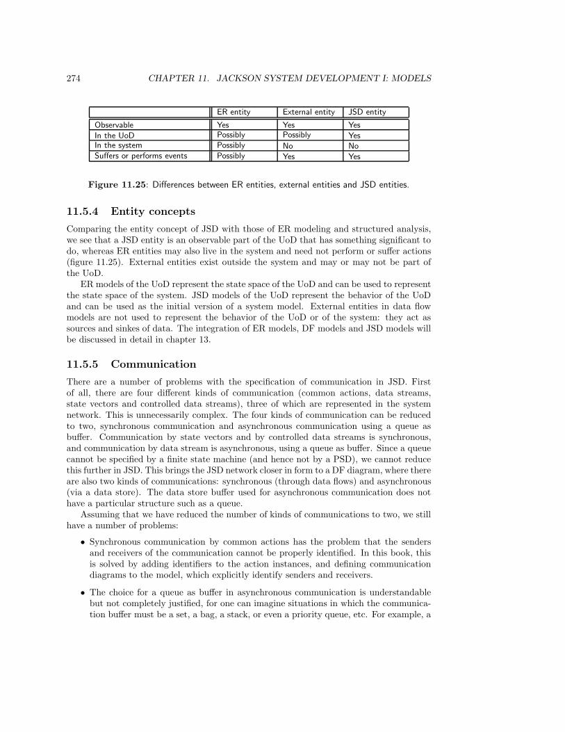
274 CHAPTER 11. JACKSON SYSTEM DEVELOPMENT I: MODELS
ER entity External entity JSD entity
Observable Yes Yes Yes
In the UoD Possibly Possibly YesIn the system Possibly No NoSuffers or performs events Possibly Yes Yes
Figure 11.25: Differences between ER entities, external entities and JSD entities.
11.5.4 Entity concepts
Comparing the entity concept of JSD with those of ER modeling and structured analysis,we see that a JSD entity is an observable part of the UoD that has something significant todo, whereas ER entities may also live in the system and need not perform or suffer actions(figure 11.25). External entities exist outside the system and may or may not be part ofthe UoD.
ER models of the UoD represent the state space of the UoD and can be used to representthe state space of the system. JSD models of the UoD represent the behavior of the UoDand can be used as the initial version of a system model. External entities in data flowmodels are not used to represent the behavior of the UoD or of the system: they act assources and sinkes of data. The integration of ER models, DF models and JSD models willbe discussed in detail in chapter 13.
11.5.5 Communication
There are a number of problems with the specification of communication in JSD. Firstof all, there are four different kinds of communication (common actions, data streams,state vectors and controlled data streams), three of which are represented in the systemnetwork. This is unnecessarily complex. The four kinds of communication can be reducedto two, synchronous communication and asynchronous communication using a queue asbuffer. Communication by state vectors and by controlled data streams is synchronous,and communication by data stream is asynchronous, using a queue as buffer. Since a queuecannot be specified by a finite state machine (and hence not by a PSD), we cannot reducethis further in JSD. This brings the JSD network closer in form to a DF diagram, where thereare also two kinds of communications: synchronous (through data flows) and asynchronous(via a data store). The data store buffer used for asynchronous communication does nothave a particular structure such as a queue.
Assuming that we have reduced the number of kinds of communications to two, we stillhave a number of problems:
• Synchronous communication by common actions has the problem that the sendersand receivers of the communication cannot be properly identified. In this book, thisis solved by adding identifiers to the action instances, and defining communicationdiagrams to the model, which explicitly identify senders and receivers.
• The choice for a queue as buffer in asynchronous communication is understandablebut not completely justified, for one can imagine situations in which the communica-tion buffer must be a set, a bag, a stack, or even a priority queue, etc. For example, a
11.6. SUMMARY 275
scheduler of elevators may receive floor service requests in a set or in a priority queuethat is periodically reorganized. The JSD notation could be made more flexible byleaving the organization of communication buffers open and specifying buffer prop-erties in the model documentation. This turns the communication buffers effectivelyinto data stores annotated with a specification of their behavior (queue, stack, set,bag, etc.)
• Synchronous communication by a controlled data stream has the problem that wemay want to define an update condition that depends upon the global state of thesystem. For example, we may perform an update on MEMBER, triggered by thecondition on LOAN that the member has 30 documents overdue. The notation wouldbe more flexible if we allow global preconditions to be specified for synchronous com-munications.
11.6 Summary
JSD and JSP both structure a system after the environment in which it will function. InJSD this means that a UoD model is built and that required system functions are specifiedin terms of this UoD model. The UoD model represents the UoD as a set of communicatingJSD entities. Each JSD entity must be discrete, exist in the UoD, have something to doand be uniquely identifiable. Each action must be discrete, exist in the UoD, occur in thelife of a JSD entity and be uniquely identifiable. Each entity has a life cycle that is built bysequencing, iteration and selection from the actions. Life cycles are represented by PSDs.Entities communicate synchronously, through common actions. The presentation of theUoD model can be improved if we represent communication by communication diagrams,also called the UoD network in this chapter.
The system network consists of surrogate processes, that represent JSD entity processes,and of function processes, that implement the system functionality. Nodes in a systemnetwork are connected by a data stream connection, which is a queue acting as a bufferbetween a sender and a receiver, by a state vector connection, which is a window that oneprocess may have on the state of another process, or by a controlled data stream connection,which is a synchronous conditional update.
Input functions accept messages from JSD entities and update the state of the corre-sponding surrogates. Output functions produce a report on the state of the system whenthey are requested to do so. Interacting functions update the state of a system processwhen a certain condition arises.
JSD models represent the state space of a system by means of the state of surrogates,long-running function processes, and data streams, and represent system transactions eitherby updates corresponding to actions in the UoD, or by function processes. The model wouldbe simplified if functions were specified declaratively. The differences between an ER modeland a JSD model of the UoD are small enough to be able to combine both models. Thedifference between the JSD system network and a DF model of the system is larger. TheJSD network partitions a network representation of system activity into three kinds ofnodes, surrogates, functions, and data streams, where a DF model has two different kindsof nodes, transformations and stores. The JSD network nodes are treated as types andthe DF nodes as instances. Communication in the JSD network is complicated, where a

276 CHAPTER 11. JACKSON SYSTEM DEVELOPMENT I: MODELS
DF model has one simple representation for synchronous communication, in terms of whichasynchronous communication is defined.
11.7 Exercises
1. Write a minispec in the pre- postcondition style for the input function REGISTER
in figure 11.21. Then make a PSD for this input function.
2. (a) Turn LATE into a short-running function (figure 11.19).
(b) Turn ACCT HISTORY into a long-running function (figures 11.15 and 11.16).
3. Each test registration by a student starts its life by a registration action, in whicha student and the university agree that the student will perform a test. It continueswith the test itself, and finishes with marking the test. These actions are orderedfor each student–test pair. Adapt the test registration model so that this ordering ofactions per test registration is expressed.
4. The rough merge in figure 11.18 leaves open the possibility that the actions of ROOM
and ALLOCATE are not properly synchronized, so that ALLOCATE continuesallocating tests to a room even after the ROOM has changed its purpose. Changethe model so that this possibility is eliminated.
11.8 Bibliographical Remarks
Jackson Structured Programming. JSP was originally defined by Jackson [157] in1975. The method is summarized by Jackson [162]. A brief and clear introduction to JSPis given by Sanden [300], who shows that it can be applied to a real-time system.
JSD. The first version of JSD was published in 1983 [158]. A brief and readable introduc-tion into JSD is given by Cameron [57]. Sanden [302] gives a brief introduction to JSD bymeans of a critical analysis of the elevator example given by Jackson [158]. Another shortintroduction is given by McNeille [226]. Sutcliffe [332] gives a good book-length introductioninto JSD.
Pamela Zave and Daniel Jackson [380] compare PSDs with state transition diagramsand argue that PSDs are useful for the specification of grammars and step-by-step instruc-tions, and state transition diagrams are useful for state-oriented descriptions. For example,premature termination is efficiently represented by state charts [137] and not by PSDs, buta sequential process such as a dialing session is more efficiently represented by PSDs. Theyshow how the strengths of both notations can be combined.
In the preparation of this chapter, I used internal course material from Michael JacksonLimited [228]. Useful supporting material, explaining the rationale of the method andcontaining a few example applications of the method, can be found in a collection editedby Cameron [56].
11.8. BIBLIOGRAPHICAL REMARKS 277
Later developments. In an interesting paper [159], Jackson sketches the following method-ological framework for describing computer-based systems: the subject domain is the realworld about which the system will compute, the target domain is the real world that itwill control, the function is a specification of the control that the system will exercise overthe target, the user domain is the agency that determines when the system must start andstop computing, and the machine domain is the hardware part of the system. He showshow several complex problems can be decomposed in different descriptions that each useelements of this framework. A simple example is the decomposition of a parsing probleminto lexical analysis, which produces lexemes as a target, and syntactic analysis, which haslexemes as its subject.
In a later work, Jackson [160] argues that the decomposition of a system model intoa UoD model and a specification of system functions is not valid for all kinds of systems.Different kinds of systems need different frameworks. This is further worked out in jointwork with Pamela Zave as a theory of multiparadigm system specification [161, 381].

Chapter 12
Jackson System DevelopmentII: Methods
12.1 Introduction
There are several versions of the JSD method [158, 228, 332]. These differ in the groupingof tasks to be performed in JSD, but they all agree on the basic philosophy that a UoDmodel should be made before a system model is made. Figure 12.1 gives a slight adaptationof the 1986 version of the method. In the modeling stage, a UoD model is made. TheJSD method for UoD modeling extends the methods already encountered for ER and DFmodeling (figure 12.2). In the network stage, a system model is made, and in the im-plementation stage, the system model is implemented. We illustrate the modeling andnetwork stages in section 12.2 by means of the circulation administration example. In sec-tion 12.3, we look at methods to evaluate the models built by JSD. Section 12.4 takes a brieflook at system implementation in JSD and section 12.5 analyzes JSD from a methodologicalpoint of view.
12.2 Case Study: the Document Circulation System
The modeling stage starts with an identification of the relevant entities and actions in theUoD. As shown in figure 12.2, we can do this by analyzing the required system transactions.These transactions are input functions, output functions or interacting functions, and wecan analyze them in the same way as we did when building an ER model. The differenceis that we are now looking for actions that occur in the UoD, and for UoD entities thatperform or suffer actions in the UoD.
The function decomposition tree in figure 8.10 lists all the input transactions of thecirculation administration. These potentially represent UoD actions performed or sufferedby UoD entities, so if we describe these transactions in elementary sentences, the chancesare that the nouns in these sentences indicate JSD entity types and the verbs JSD actions:
• A MEMBER reserves a TITLE.
• A MEMBER reserves a DOCUMENT .
279
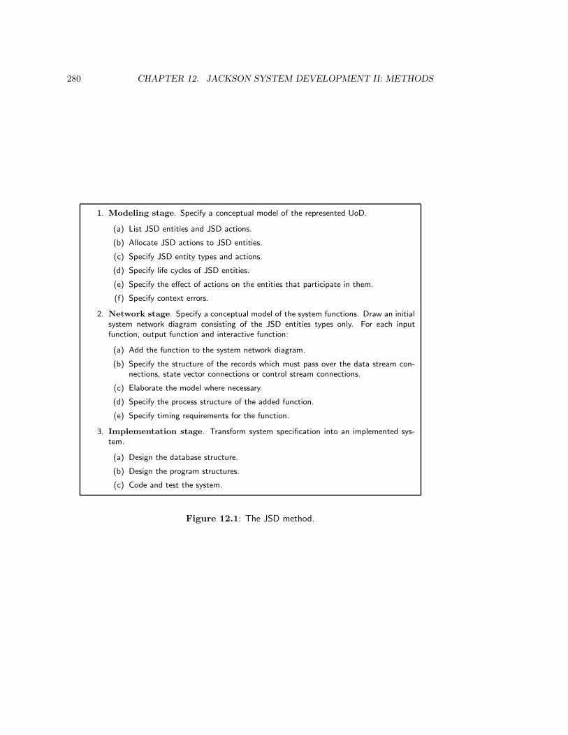
280 CHAPTER 12. JACKSON SYSTEM DEVELOPMENT II: METHODS
1. Modeling stage. Specify a conceptual model of the represented UoD.
(a) List JSD entities and JSD actions.
(b) Allocate JSD actions to JSD entities.
(c) Specify JSD entity types and actions.
(d) Specify life cycles of JSD entities.
(e) Specify the effect of actions on the entities that participate in them.
(f) Specify context errors.
2. Network stage. Specify a conceptual model of the system functions. Draw an initialsystem network diagram consisting of the JSD entities types only. For each inputfunction, output function and interactive function:
(a) Add the function to the system network diagram.
(b) Specify the structure of the records which must pass over the data stream con-nections, state vector connections or control stream connections.
(c) Elaborate the model where necessary.
(d) Specify the process structure of the added function.
(e) Specify timing requirements for the function.
3. Implementation stage. Transform system specification into an implemented sys-tem.
(a) Design the database structure.
(b) Design the program structures.
(c) Code and test the system.
Figure 12.1: The JSD method.

12.2. CASE STUDY: THE DOCUMENT CIRCULATION SYSTEM 281
Functiondecomposition
tree,Scenarios
TransactionsTransaction/use
tableEntityanalysis
Transactiondecomposition
table
Naturallanguage
text
Elementarysentences
ER model ofUoD or SuD
Naturallanguageanalysis
Recorddeclarations
Recordanalysis
Forms
Formanalysis
Processanalysis
DF modelof SuD
Essential modelof current system
Essential systemanalysis
Currentsystem
Event–responselist
Eventpartitioning
JSD entities,JSD actions
Natural languageanalysis
Actionallocation
JSD modelof UoD
JSD modelof SuD
Figure 12.2: Road map for finding ER, DF and JSD models of the UoD, the current system,or the SuD.
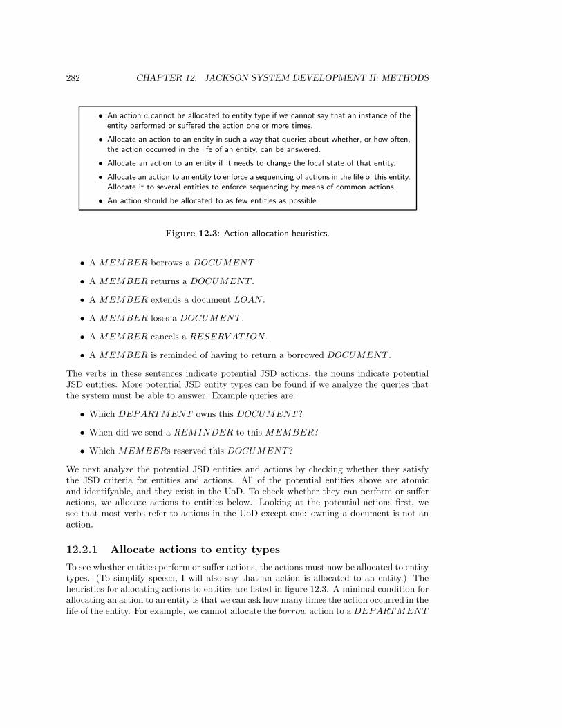
282 CHAPTER 12. JACKSON SYSTEM DEVELOPMENT II: METHODS
• An action a cannot be allocated to entity type if we cannot say that an instance of theentity performed or suffered the action one or more times.
• Allocate an action to an entity in such a way that queries about whether, or how often,the action occurred in the life of an entity, can be answered.
• Allocate an action to an entity if it needs to change the local state of that entity.
• Allocate an action to an entity to enforce a sequencing of actions in the life of this entity.Allocate it to several entities to enforce sequencing by means of common actions.
• An action should be allocated to as few entities as possible.
Figure 12.3: Action allocation heuristics.
• A MEMBER borrows a DOCUMENT .
• A MEMBER returns a DOCUMENT .
• A MEMBER extends a document LOAN .
• A MEMBER loses a DOCUMENT .
• A MEMBER cancels a RESERV ATION .
• A MEMBER is reminded of having to return a borrowed DOCUMENT .
The verbs in these sentences indicate potential JSD actions, the nouns indicate potentialJSD entities. More potential JSD entity types can be found if we analyze the queries thatthe system must be able to answer. Example queries are:
• Which DEPARTMENT owns this DOCUMENT ?
• When did we send a REMINDER to this MEMBER?
• Which MEMBERs reserved this DOCUMENT ?
We next analyze the potential JSD entities and actions by checking whether they satisfythe JSD criteria for entities and actions. All of the potential entities above are atomicand identifyable, and they exist in the UoD. To check whether they can perform or sufferactions, we allocate actions to entities below. Looking at the potential actions first, wesee that most verbs refer to actions in the UoD except one: owning a document is not anaction.
12.2.1 Allocate actions to entity types
To see whether entities perform or suffer actions, the actions must now be allocated to entitytypes. (To simplify speech, I will also say that an action is allocated to an entity.) Theheuristics for allocating actions to entities are listed in figure 12.3. A minimal condition forallocating an action to an entity is that we can ask how many times the action occurred in thelife of the entity. For example, we cannot allocate the borrow action to a DEPARTMENT

12.2. CASE STUDY: THE DOCUMENT CIRCULATION SYSTEM 283
reserve borrow cancel borrow extend return lose remind
title res
DOCUMENT U
FINE C
LOAN C C U D D U
MEMBER
RESERV ATION C D D
TITLE
Figure 12.4: Action allocation table for a model of the circulation UoD. This is a simplifiedform of the transaction decomposition table.
because we cannot ask how many times the department is borrowed. If an action occurs inthe life of an entity, then this is relevant for the system if the system must answer queriesabout this action. For example, if the system must be able to answer the query whetherthis document is borrowed, then we should allocate borrow to DOCUMENT .
Actions must also be allocated to entities whose state they change. For example, ifborrow would change the state of a DOCUMENT , we should allocate it to DOCUMENT
as well as to LOAN . The definition of the effect of borrow in the DOCUMENT life cycleis local to the DOCUMENT entity in whose life borrow occurs, and is similar to the effectof borrow on the LOAN life cycle.
Enforcing sequencing by means of common actions can be done as follows. In fig-ure 11.11, the life cycle of a CUSTOMER is an iteration over the actions place, amend,cancel and deliver in any order. There are constraints on the ordering of these actions, suchas that an order cannot be delivered after it is canceled, but these are not expressible inthe customer life cycle, for these constraints are valid per order, not per customer. In orderto express them we must therefore introduce an ORDER entity type and define the lifecycle of an ORDER. This life cycle is shown in figure 11.11. The common actions betweenORDER and CUSTOMER enforce the proper ordering of actions in the life cycle of aCUSTOMER.
Applying these criteria to the lists of potential JSD actions and entity types, we get theaction allocation table shown in figure 12.4. This is a simplified version of the transactiondecomposition table, in which all R entries are omitted. The reason for omitting these entriesis that reading the state of an entity is part of testing the preconditions of an action, butit does not mean that the action is allocated to the entity whose state it reads. An actionmust be allocated at least to the entities whose state it changes. Hence, we see all the C, Uand D entries in an action allocation table. We also may see an occasional R entry if oneof the other heuristics forces us to allocate an action to an entity whose state it reads.
The decisions made in building the action allocation table for the circulation UoD areexplained below.
• To keep the model simple, we ignore reserve doc. Addition of this action is notdifficult and is left as an exercise.
• reserve title. This creates a RESERV ATION , so we should at least allocate thisaction to this entity type. Because a reserve title is performed by a MEMBER and
284 CHAPTER 12. JACKSON SYSTEM DEVELOPMENT II: METHODS
is directed at a TITLE, it seems natural to allocate reserve title to these entity typesas well. However, the event does not change the state of any entity of these types.Neither do we need to allocate reserve title to TITLE to remember the fact thatreserve title occurred in the life of a title. If we would define an attribute
title : RESERV ATION → TITLE IDENTIFIER,
then all this information could be retrieved by means of this attribute. The codomainof this attribute should be some unique identification of TITLE instances, e.g. a keyor an identifier attribute. We therefore allocate reserve title to RESERV ATION
only.
• borrow. This creates a LOAN instance, so we must allocate it to LOAN . By a similarargument as above, we decide not to allocate it to MEMBER and DOCUMENT
but define an attribute
document : LOAN → DOCUMENT IDENTIFIER.
If we want to find out whether a document d is borrowed, we should look at the setof existing LOAN instances and search for one whose document is d. If the LOAN
is done by a member who reserved the document (or the title of the document), thenthis reservation instance should be destroyed simultaneously with the creation of theLOAN instance. This suggests that in some cases, borrow should also be allocated toRESERV ATION (as the last event in its life cycle). However, it is not possible todefine a conditional participation in an action. Instead, we define a second transaction,borrow res.
• borrow res. This is a borrow action that terminates a reservation and starts a LOAN .We allocate borrow res to RESERV ATION and LOAN .
• cancel. This terminates a RESERV ATION , so we allocate it to this entity type. Wedon’t allocate it to MEMBER, because we don’t expect queries about how often amember canceled a reservation and cancel does not change the state of a MEMBER.
• extend. This changes the state of LOAN , so we allocate it to this entity type.
• return. This terminates the existence of a LOAN , so we allocate it to this entitytype.
• lose. This terminates a LOAN , so we allocate it to this entity type. In addition, itchanges the state of a document from present to lost. If we delete a LOAN whenthe borrowed document is lost, then the information that the document is lost isnot represented anywhere. We therefore add an attribute lost to DOCUMENT andinitialize it to false. The effect of lose is to set this attribute to true. We thereforealso allocate lose to DOCUMENT .
Yet another effect of lose(m, d) is that m should pay a fine. We do this by introducinga FINE entity type, with a history in which such events as pay and waive can takeplace. Instances of FINE would be created by the circulation desk but be handledby the finance department. Thus, FINE instances are a means of communicationbetween these two departments. The lose action is also allocated to FINE and shouldbe the first event in the FINE life cycle.

12.2. CASE STUDY: THE DOCUMENT CIRCULATION SYSTEM 285
DOCUMENT (doc id, title id, location, . . .)
FINE(pass nr, total amount, amount paid, amount waived)
LOAN(pass nr, doc id, date borrowed, return date)
MEMBER(pass nr, name, address, . . .)
RESERV ATION(pass nr, title id, date reserved)
TITLE(title id, name, authors, publisher, year, isbn, . . .)
Figure 12.5: Entity types in the circulation desk UoD and their attributes.
• remind. A MEMBER is sent a reminder for returning a DOCUMENT , but thisreminder is sent because a LOAN is extended too long. One member can be overduefor many LOANS, so we allocate remind to LOAN .
• The entity type DEPARTMENT has been omitted because there is no action for itin the UoD of the circulation desk.
• The entity type REMINDER has been omitted because it is suggested by a querythat asks when the last reminder was sent for a document, and we can answer thisquery without introducing this entity type. For example, we can have the LOAN
surrogate fill a data stream with remind messages, which is read by the query. Notethat if we had kept REMINDER as an entity type, then the remind action wouldhave been the creation action for this type.
The action allocation table shows that in our UoD model, MEMBER and TITLE are noJSD entities, because there are no actions in their lives. The reason for this is that we havea model of the world as viewed by the circulation desk. There are other views of the UoD,such as that of the member services department or the acquisition department, in whichthere are relevant actions that must be allocated to MEMBER or TITLE. For example,MEMBER actions like become member and change address will appear in a model ofthe UoD of the member services department, and TITLE actions like order, arrive andclassify will appear in the UoD model of the acquisition department.
12.2.2 Specify JSD entity types and actions
Now that we have reasonable certainty about what the relevant JSD actions and entitytypes are, we specify them in more detail. The following items are specified:
• JSD entity type declarations, including their attributes. We do this in the same wayas in ER modeling. Figure 12.5 contains the JSD entity specifications, with keysunderlined.
• JSD actions are declared by listing their parameters and by giving an intuitive expla-nation of their meaning. Actions are specified in figure 12.6.
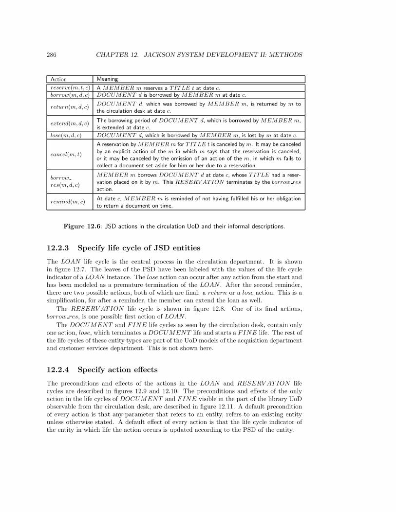
286 CHAPTER 12. JACKSON SYSTEM DEVELOPMENT II: METHODS
Action Meaning
reserve(m, t, c) A MEMBER m reserves a TITLE t at date c.borrow(m,d, c) DOCUMENT d is borrowed by MEMBER m at date c.
return(m,d, c)DOCUMENT d, which was borrowed by MEMBER m, is returned by m tothe circulation desk at date c.
extend(m,d, c)The borrowing period of DOCUMENT d, which is borrowed by MEMBER m,is extended at date c.
lose(m,d, c) DOCUMENT d, which is borrowed by MEMBER m, is lost by m at date c.
cancel(m, t)
A reservation by MEMBER m for TITLE t is canceled by m. It may be canceledby an explicit action of the m in which m says that the reservation is canceled,or it may be canceled by the omission of an action of the m, in which m fails tocollect a document set aside for him or her due to a reservation.
borrow
res(m,d, c)
MEMBER m borrows DOCUMENT d at date c, whose TITLE had a reser-vation placed on it by m. This RESERV ATION terminates by the borrow res
action.
remind(m, c)At date c, MEMBER m is reminded of not having fulfilled his or her obligationto return a document on time.
Figure 12.6: JSD actions in the circulation UoD and their informal descriptions.
12.2.3 Specify life cycle of JSD entities
The LOAN life cycle is the central process in the circulation department. It is shownin figure 12.7. The leaves of the PSD have been labeled with the values of the life cycleindicator of a LOAN instance. The lose action can occur after any action from the start andhas been modeled as a premature termination of the LOAN . After the second reminder,there are two possible actions, both of which are final: a return or a lose action. This is asimplification, for after a reminder, the member can extend the loan as well.
The RESERV ATION life cycle is shown in figure 12.8. One of its final actions,borrow res, is one possible first action of LOAN .
The DOCUMENT and FINE life cycles as seen by the circulation desk, contain onlyone action, lose, which terminates a DOCUMENT life and starts a FINE life. The rest ofthe life cycles of these entity types are part of the UoD models of the acquisition departmentand customer services department. This is not shown here.
12.2.4 Specify action effects
The preconditions and effects of the actions in the LOAN and RESERV ATION lifecycles are described in figures 12.9 and 12.10. The preconditions and effects of the onlyaction in the life cycles of DOCUMENT and FINE visible in the part of the library UoDobservable from the circulation desk, are described in figure 12.11. A default preconditionof every action is that any parameter that refers to an entity, refers to an existing entityunless otherwise stated. A default effect of every action is that the life cycle indicator ofthe entity in which life the action occurs is updated according to the PSD of the entity.
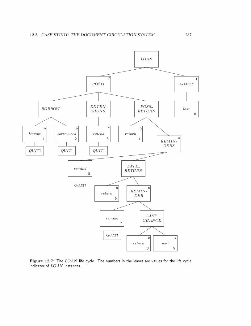
12.2. CASE STUDY: THE DOCUMENT CIRCULATION SYSTEM 287
LOAN
POSIT
?
ADMIT
?
BORROWEXTEN -SIONS
POSS
RETURNlose
10
borrow
o
1
QUIT !
borrow res
o
2
QUIT !
extend
*
3
QUIT !
return
o
4REMIN -
DERS
o
remind
5
QUIT !
LATE
RETURN
return
o
6
REMIN -DER
o
remind
7
QUIT !
LAST
CHANCE
return
o
8
null
o
9
Figure 12.7: The LOAN life cycle. The numbers in the leaves are values for the life cycleindicator of LOAN instances.
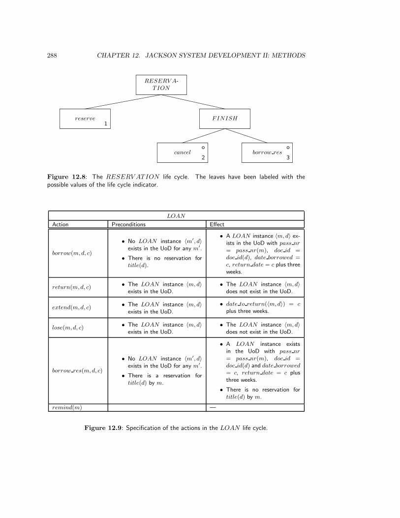
288 CHAPTER 12. JACKSON SYSTEM DEVELOPMENT II: METHODS
RESERV A-TION
reserve1
FINISH
cancelo
2borrow res
o
3
Figure 12.8: The RESERV ATION life cycle. The leaves have been labeled with thepossible values of the life cycle indicator.
LOAN
Action Preconditions Effect
borrow(m,d, c)
• No LOAN instance 〈m′, d〉exists in the UoD for any m′.
• There is no reservation fortitle(d).
• A LOAN instance 〈m,d〉 ex-ists in the UoD with pass nr
= pass nr(m), doc id =doc id(d), date borrowed =c, return date = c plus threeweeks.
return(m,d, c) • The LOAN instance 〈m, d〉exists in the UoD.
• The LOAN instance 〈m,d〉does not exist in the UoD.
extend(m,d, c) • The LOAN instance 〈m, d〉exists in the UoD.
• date to return(〈m,d〉) = c
plus three weeks.
lose(m,d, c) • The LOAN instance 〈m, d〉exists in the UoD.
• The LOAN instance 〈m,d〉does not exist in the UoD.
borrow res(m,d, c)
• No LOAN instance 〈m′, d〉exists in the UoD for any m′.
• There is a reservation fortitle(d) by m.
• A LOAN instance existsin the UoD with pass nr
= pass nr(m), doc id =doc id(d) and date borrowed
= c, return date = c plusthree weeks.
• There is no reservation fortitle(d) by m.
remind(m) —
Figure 12.9: Specification of the actions in the LOAN life cycle.
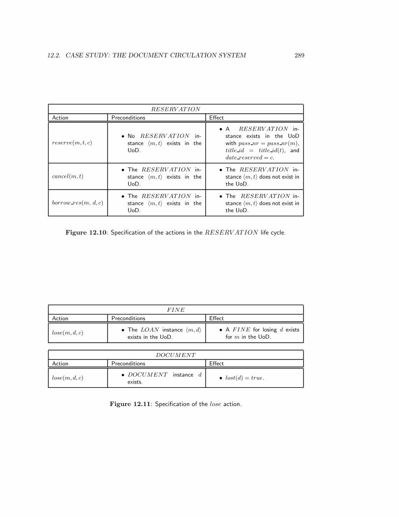
12.2. CASE STUDY: THE DOCUMENT CIRCULATION SYSTEM 289
RESERV ATION
Action Preconditions Effect
reserve(m, t, c)• No RESERV ATION in-
stance 〈m, t〉 exists in theUoD.
• A RESERV ATION in-stance exists in the UoDwith pass nr = pass nr(m),title id = title id(t), anddate reserved = c.
cancel(m, t)• The RESERV ATION in-
stance 〈m, t〉 exists in theUoD.
• The RESERV ATION in-stance 〈m, t〉 does not exist inthe UoD.
borrow res(m, d, c)• The RESERV ATION in-
stance 〈m, t〉 exists in theUoD.
• The RESERV ATION in-stance 〈m, t〉 does not exist inthe UoD.
Figure 12.10: Specification of the actions in the RESERV ATION life cycle.
FINE
Action Preconditions Effect
lose(m,d, c) • The LOAN instance 〈m, d〉exists in the UoD.
• A FINE for losing d existsfor m in the UoD.
DOCUMENT
Action Preconditions Effect
lose(m,d, c)• DOCUMENT instance d
exists.• lost(d) = true.
Figure 12.11: Specification of the lose action.

290 CHAPTER 12. JACKSON SYSTEM DEVELOPMENT II: METHODS
RESERV ATION Context error table
LCI Update OK/ Condition Error messageError
0 reserve(m, t, c) OK
cancel(m, t) ErrorTitle is not reserved by mem-ber.
borrow res(m,d, c) Errortitle(d) is not reserved bymember.
1 reserve(m, t, c) ErrorTitle already reserved by mem-ber.
cancel(m, t) OKborrow res(m,d, c) OK
2, 3 All No reservation.
Figure 12.12: Context error table for RESERV ATION .
12.2.5 Context errors
A context error is an attempt to inform the system that an JSD action occurred in theUoD that could not occur according to the PSDs of the UoD model. These errors canbe systematically listed in a context error table, which can then be used in the specifica-tion of error-handling in input functions. Figure 12.12 gives a context error table for theRESERV ATION process.
12.2.6 System functions
Examples of input, output and interacting functions have been given in chapter 11. Inthis section we give another example of an interacting function and in the exercises, thereis another example of an output function. The interacting function to be specified is thefollowing:
F1 Each day at 9:00 in the morning, suspend each member who has not responded forsix weeks to a reminder.
A system network and a possible process structure for F1 are shown in figure 12.13. F1requires elaboration of the UoD model and of the system specification. The UoD modelmust be extended with a suspend action in the MEMBER life cycle, and the systemspecification must be extended by adding the attribute date last reminded to the LOAN
entity type,
LOAN(pass nr, doc id, date to return, date last reminded).
Finally, the table of effect definitions must be updated with the effect of the actions on thisattribute, as shown in figure 12.14.
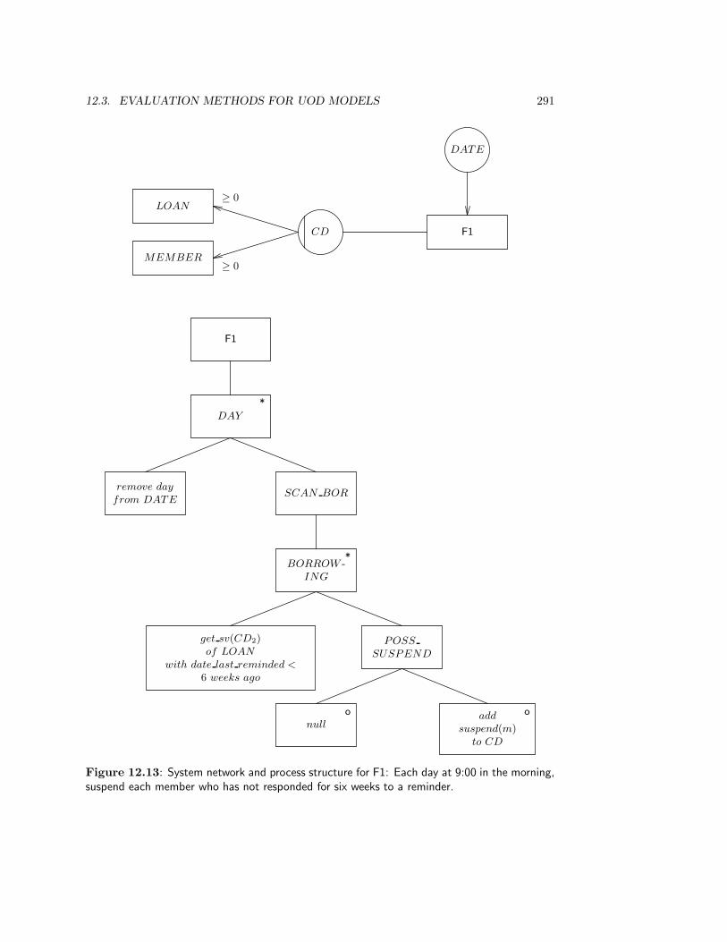
12.3. EVALUATION METHODS FOR UOD MODELS 291
F1
DAY
*
remove day
from DATESCAN BOR
BORROW -ING
*
get sv(CD2)of LOAN
with date last reminded <
6 weeks ago
POSS
SUSPEND
null
o add
suspend(m)to CD
o
F1
LOAN
MEMBER
CD
DATE
≥ 0
≥ 0
Figure 12.13: System network and process structure for F1: Each day at 9:00 in the morning,suspend each member who has not responded for six weeks to a reminder.
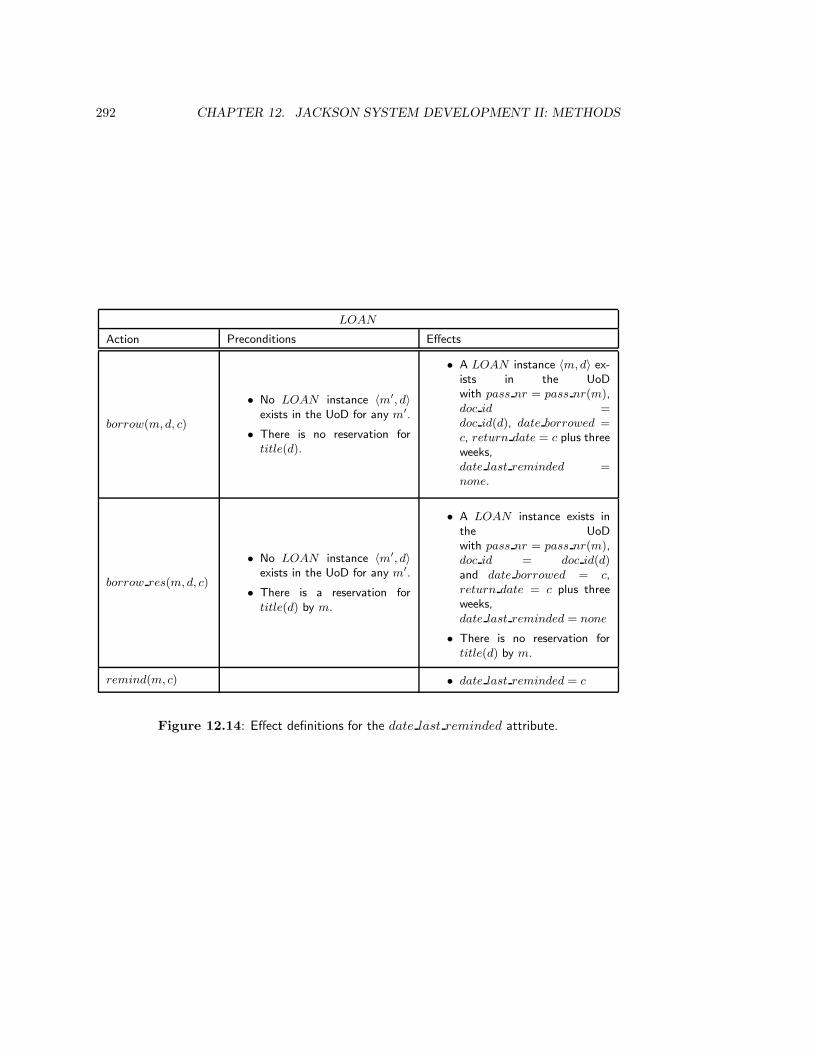
292 CHAPTER 12. JACKSON SYSTEM DEVELOPMENT II: METHODS
LOAN
Action Preconditions Effects
borrow(m,d, c)
• No LOAN instance 〈m′, d〉exists in the UoD for any m′.
• There is no reservation fortitle(d).
• A LOAN instance 〈m,d〉 ex-ists in the UoDwith pass nr = pass nr(m),doc id =doc id(d), date borrowed =c, return date = c plus threeweeks,date last reminded =none.
borrow res(m,d, c)
• No LOAN instance 〈m′, d〉exists in the UoD for any m′.
• There is a reservation fortitle(d) by m.
• A LOAN instance exists inthe UoDwith pass nr = pass nr(m),doc id = doc id(d)and date borrowed = c,return date = c plus threeweeks,date last reminded = none
• There is no reservation fortitle(d) by m.
remind(m, c) • date last reminded = c
Figure 12.14: Effect definitions for the date last reminded attribute.

12.3. EVALUATION METHODS FOR UOD MODELS 293
Entity checks:
• A JSD entity exists in the represented UoD, not merely in the DBS.
• A JSD entity must be able to perform or suffer actions.
• JSD entities must be atomic.
• A JSD entity must have a unique identity.
Action checks:
• Actions must occur in the represented UoD, not merely in the DBS.
• Actions are discrete in time.
• Actions cannot be decomposed in more elementary actions.
• Each action must have a unique identity.
Action allocation checks:
• An action cannot be allocated to an entity if we cannot ask how often the actionoccurred in the life of the entity.
• An action must be allocated to an entity if the system must remember occurrencesof this action in the life of the entity.
• An action should be allocated to an entity if it needs to update the local state of theentity.
• Every entity should be created (deleted) sometime.
Common action checks:
• A message is delivered as sent.
• A message is never delivered at the incorrect address.
• There is no delay between sending and receiving.
Life cycle check:
• It should be impossible for a JSD entity to behave in another way than that describedby its PSD.
Figure 12.15: Quality checks for JSD models.

294 CHAPTER 12. JACKSON SYSTEM DEVELOPMENT II: METHODS
12.3 Evaluation Methods for UoD Models
Figure 12.15 summarizes a number of criteria by which to evaluate a model of the UoD.Most of them are simply a summary of the defining characteristics of the main concepts ofUoD modeling. Only the life cycle certainty check is new. This check says that a life cyclegives a necessary process structure that covers all possible histories of a class of entities. Itis an important quality check that prevents us from overlooking any exceptions, interrupts,premature terminations, etc., in the life of an entity. There are no evaluation criteria forthe specification of system functions. If the function processes are specified following theJSP method, then they are guaranteed to be well-structured programs.
12.4 Implementation
The output of the network stage is a model of required system behavior that assumes anunbounded supply of processors, one for each surrogate process and function process, anda sufficient number of unbounded queues to act as data streams between processes. Theimplementation stage is concerned with mapping this abstract model to a model of a systemwith only one processor and limited memory. A simple way to transform a system networkinto a model of the implementation on a single-processor system is the following:
• Each surrogate process and each long-running function process becomes a modulein the implementation. Short-running functions become modules that don’t have aninternal state that survives a call to the module.
• The state vectors of surrogates and long-running function processes are gathered to-gether in files or global variables. There is one file or state variable for each surrogatetype and for each long-running function process. This is called state vector sepa-ration.
• Each data stream is implemented as a file with a first-in first-out access discipline.Data stream access in the system modules is replaced by the appropriate file accessstatements.
• A scheduler reads all input to the system and calls any module in the system directly.When an update to a surrogate state is received, it calls the appropriate module onthe appropriate state vector and advances the life cycle indicator of the surrogateaccordingly.
This particular implementation strategy leads to a flat system, for each module is directlycalled by the scheduler. More refined implementation strategies are described in the litera-ture on JSD, listed at the end of this chapter.
12.5 Methodological Analysis
12.5.1 Separation of UoD modeling from function specification
Jackson [158] motivates the JSD method by contrasting it with functional decompositionas practiced in structured analysis. He shows convincingly that a model of required system

12.5. METHODOLOGICAL ANALYSIS 295
behavior that is based upon a model of UoD behavior is more maintainable than a modelthat decomposes a system into subsystems that correspond to required system functions.The reason is simple: the UoD is more stable than the system requirements. The UoD is thepart of the world about which the system computes. The UoD may consist of entities andprocesses that make up part of the business, or it may consist of entities whose behavior is tobe controlled by the system. Either way, the entities and processes are more stable than thedesires of system users. Requirements may change from requesting simple snapshot reportsto requesting periodical historical summary reports or to complex interacting functions. Allthese functions are described in terms of the same UoD. If the system were structured ina hierarchical manner of a function decomposition tree, then any change in this tree couldcause a major restructuring of the system. If the system is structured by separating theUoD model from the implementation of system functions, then a change in system functioncan remain localized to the affected function; the UoD model will remain constant duringthose changes.
An added benefit of building a separate UoD model is that this can serve as a commonbasis for understanding system behavior and for specifying system functions. The UoDmodel serves as a means of communication between customers, users, domain specialistsand system developers.
12.5.2 JSD and Information Engineering
The above argument is built upon the same premise as Information Engineering, viz. thatthe UoD is more stable than human desires. The conclusion drawn from this premise is,however, different. Where Information Engineering concludes that the information strategyof a business must be based upon the foundation of a business data model (which is an ERmodel of the business UoD), JSD concludes that an information system must be structuredby separating a UoD model from a model of system functions. The common denominator inthese two different conclusions is that both methods agree that a UoD model must serve asa shared model in terms of which system requirements must be understood. The differenceis that Information Engineering maintains a focus on functional decomposition of businessneeds, where JSD maintains a focus on system specification.
12.5.3 JSD and structured development
Note that JSD assumes that structured analysis leads to a system structure that is isomor-phic to the function decomposition tree. We have seen in the methodological analyses ofISP (subsection 6.6.2) and data flow models (subsection 9.7.3) that function decompositionis orthogonal to system decomposition. Decomposing the product idea into functions downto the level of transactions yields a decomposition tree of the product idea that stays at onelevel of aggregation. This decomposition moves to the right along the horizontal dimen-sion of the development framework of figure 3.9 (page 53). Decomposition of the productinto parts leads us to the next lower level of aggregation. This is a movement downwardsin the vertical dimension of the framework. It is only when we identify the two kinds ofdecomposition that we get into the maintainability trouble pointed out by Jackson. Thereis no assumption in structured development that system decomposition should be isomor-phic to function decomposition — however, neither is there a guideline to keep these twodecompositions distinct.
296 CHAPTER 12. JACKSON SYSTEM DEVELOPMENT II: METHODS
A related critique of JSD on function decomposition is that top-down decomposition ofa problem only works well if we already know what the subproblems are. In the face ofuncertainty about the solution, top-down decomposition of a problem is more likely to giveus a wrong decomposition. Here, JSD assumes that a function decomposition tree is builttop-down. There is no such assumption in structured development. The tree can be builttop-down, bottom-up, middle out or in any other way, and in whatever way it is built weare likely to iterate many times before a stable tree is reached. The function decompositiontree is a representation of the product functions, not of the process by which we found thosefunctions.
12.5.4 Modeling social processes
An important limitation of the JSD method is that life cycle modeling is only applicable ina limited manner to social systems. For example, the circulation desk model we developedin this chapter contains omissions in the dynamics of the represented UoD. Documentscan be lost, but they can also be found, something we did not put in our model. Finesmay be waived or refunded. Documents may get lost without being borrowed, and theymay be damaged by their borrowers, or by other libraries, or by the binding department.Documents come in many forms: books, maps, journals, serial volumes, dossiers for whichregular updates are published, manuals, and hand-written manuscripts; and many of thesecan appear on paper, microfiche or CD-ROM. All of these behave differently. If we includeall of this in our UoD model, we get an extremely complex document life cycle and we cannever be sure that we have really modeled all possibilities, or that new kinds of documentswill not come into being. There is a trade-off between the complexity of the UoD model andthe returns on this investment in terms of the utility of the model. If the UoD is mechanical,such as in an elevator system, it may be necessary as well as feasible to make a completelife cycle model of the UoD. But in the case of social systems, the number of exceptions,interrupts, premature terminations and backtrackings may be so high as to reduce the lifecycle to the simple structure create; do anything∗; delete.
12.6 Summary
The JSD method consists of three stages, modeling the UoD, modeling the DBS and im-plementing the DBS. A UoD model can be found by an elementary sentence analysis ofrequired system transactions or by analyzing a transaction system decomposition tablethat was already found by other means. The action allocation table is a simplified formof the transaction decomposition table and represents the communication structure withineach system transaction. The evaluation methods for UoD models all follow from the def-initions of the key JSD concepts such as JSD entity, JSD action, common action and lifecycle.
The emphasis on the stability of the UoD model is shared with Information Engineering.Maintainability of the system is enhanced if it is structured after the UoD model ratherthan after the tree of required system functions. The UoD model can also serve as a com-mon framework for communication about required system functions. A possible problemwith JSD is that social processes do not have the required regularity to be modeled byanything other than an unstructured iteration over arbitrary actions between birth and
12.7. EXERCISES 297
death. Although JSD is contrasted with structured development, the critique that struc-tured development requires a system to be structured top-down according to the functiondecomposition tree is unfounded.
12.7 Exercises
1. Reservations can be canceled because the reserver notifies the library of cancellation,or because ten days have passed since the reserver has been notified by the libraryof the availability of the reserved title. Change the system model by adding thisfunction.
2. Add the entity type D RESERV ATION for document reservations to the UoDmodel of the library. Define a PSD for this entity type and make any other changesnecessary to accommodate this process.
3. Assume that all fines of a MEMBER are collected in one FINE entity, so that therelationship between MEMBER and FINE would be one-one. Revise the modelaccordingly.
4. Define the system function F2: At the end of each week, make a list of borrowingactions that occurred in that week; add to this list a count of the loans of that week,plus a cumulative total of loans.
12.8 Bibliographical Remarks
Literature on the JSD method has already been given in the bibliographical section ofthe previous chapter. Case studies in the application of JSD can be found in Jack-son’s book [158], a collection of papers edited by Cameron [56], in Sutcliffe [332] and inSanden [303].

Part III
Method Integration andStrategy Selection
299

Chapter 13
A Framework for RequirementsEngineering I: Models
13.1 Introduction
In this final part, we turn to the integration of the requirements specification methods ofpart II. In this chapter, we focus on integration of the modeling structures used in thosemethods and in the next, we concentrate on the integration of the methods to find and eval-uate requirements specifications. We reviewed two kinds of methods in part II, methods forneeds analysis at the organizational level (ISAC change analysis and Information StrategyPlanning) and methods for behavior specification at the level of computer-based systems.In section 13.2, we show how the deliverables of ISAC change analysis and InformationStrategy Planning can be integrated. In section 13.3, we turn to behavior specificationsand compare the notations and techniques used in ER modeling, Structured Analysis andJSD by placing them in the framework for behavior specifications defined of chapter 4. Insection 13.4 we then show how the notations of ER modeling and JSD can be integrated andin section 13.5, we show how to extend this with the DF modeling notation. In section 13.6,we step back and look at the different concepts of modularization used in the DF modelsand JSD models of a system.
13.2 The Specification of Product Objectives
In chapter 4, it was explained how the analysis of needs results in a specification of toplevel product objectives. If the product is a computer-based system, its environment is asocial system and the the top level objectives must follow from an analysis of the needs inthis social environment. ISAC Change Analysis and IE Information Strategy Planning aretwo methods to analyze the needs of the social environment. There are three characteristicsshared by both methods:
• Both are methods to develop information systems.
• Both are methods for client-oriented development.
301

302 A FRAMEWORK FOR REQUIREMENTS MODELS
• Both methods represent the human activity in the environment of the SuD (by activitymodels and function decomposition trees).
The restriction of Change Analysis and ISP to information systems is not significant, be-cause at this stage of development it is immaterial what kind of system will eventually bedeveloped. The restriction to client-oriented development is more significant, because themethods and techniques recommended by Change Analysis and ISP can only be used forthe analysis of individual clients and not for the analysis of a market. To analyze the needsof a market, one should turn to methods like Quality Function Deployment (QFD). In thismethod, product characteristics are analyzed from the viewpoint of users of the product,and these characteristics are translated into design characteristics of the product. The de-sign characteristics then become the top level product objectives. Pointers to the literatureon QFD are given in section 13.10.
Within the above shared orientation, there are three important differences betweenChange Analysis and ISP:
• In Change Analysis, needs follow from an analysis of problems experienced by anorganization. In ISP, needs follow from an analysis of the strategy of the organization.
• In Change Analysis, the activity model represents interactions between activities.There is a hierarchical structure of the models, but this is not represented explic-itly. Material or data manipulated by the activities is represented by stores. In ISP,the activity model is a tree that represents the contribution of each activity to theorganization mission.
• ISP additionally represents the UoD of the business by an entity model. Interac-tion between data and activities is represented by a function/entity matrix. Entitymodeling is absent from ISAC.
These differences are such that both methods supplement each other. Figure 13.1 showsan ER diagram of concepts from both methods and of some of the relationships betweenthe concepts. Cardinalities are omitted; adding these is left as an exercise. Going fromthe top down, we see that interventions may solve some problems and introduce otherproblems, and that problems have owners and inhibit goals. The relationship PG is thematrix of problems against problem owners made in Change Analysis. Product objectivesare objectives, which are subgoals, which are goals. The is a fork below GOAL is intendedto represent that all goals are either subgoals or missions. Not all subgoals are objectives,though, and not all objectives are product objectives. Goals form a hierarchy whose rootis the business mission.
Persons are employed by organization units, may be members of groups that have prob-lems, and may, as managers, want to monitor CSFs because they view these as indicatorsof goal achievement. Some organization units can be decomposed into other units. Activi-ties are performed by organization units and form a function decomposition tree. In orderto avoid crossing lines, MISSION appears twice in the diagram. The hierarchy of thefunction decomposition tree corresponds in ISAC to the hierarchy of activity models.
The interaction between activities is represented by the INTERACTION relationshipand the interaction between activities and entities is represented by the CRUD relationship.The CRUD relationship is the function/entity matrix of ISP. The union of the CRUD and
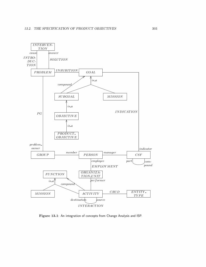
13.2. THE SPECIFICATION OF PRODUCT OBJECTIVES 303
GOALINHIBITION
PROBLEM
INTERV EN -TION
SOLUTIONINTRO-
DUC-TION
cause answer
SUBGOAL MISSION
is a
compound
OBJECTIV E
is a
PRODUCT
OBJECTIV E
is a
GROUP
PG
problem
owner
PERSONmanagermember
CSF
part com-pound
INDICATION
indicator
employee
EMPLOY MENT
ORGANIZA-TION UNIT
performer
ACTIV ITY
FUNCTION
MISSION
is acompound
ENTITY
TY PE
CRUD
destination source
INTERACTION
Figure 13.1: An integration of concepts from Change Analysis and ISP.
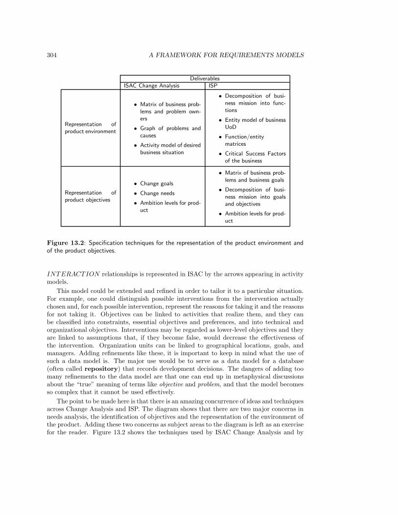
304 A FRAMEWORK FOR REQUIREMENTS MODELS
DeliverablesISAC Change Analysis ISP
Representation ofproduct environment
• Matrix of business prob-lems and problem own-ers
• Graph of problems andcauses
• Activity model of desiredbusiness situation
• Decomposition of busi-ness mission into func-tions
• Entity model of businessUoD
• Function/entitymatrices
• Critical Success Factorsof the business
Representation ofproduct objectives
• Change goals
• Change needs
• Ambition levels for prod-uct
• Matrix of business prob-lems and business goals
• Decomposition of busi-ness mission into goalsand objectives
• Ambition levels for prod-uct
Figure 13.2: Specification techniques for the representation of the product environment andof the product objectives.
INTERACTION relationships is represented in ISAC by the arrows appearing in activitymodels.
This model could be extended and refined in order to tailor it to a particular situation.For example, one could distinguish possible interventions from the intervention actuallychosen and, for each possible intervention, represent the reasons for taking it and the reasonsfor not taking it. Objectives can be linked to activities that realize them, and they canbe classified into constraints, essential objectives and preferences, and into technical andorganizational objectives. Interventions may be regarded as lower-level objectives and theyare linked to assumptions that, if they become false, would decrease the effectiveness ofthe intervention. Organization units can be linked to geographical locations, goals, andmanagers. Adding refinements like these, it is important to keep in mind what the use ofsuch a data model is. The major use would be to serve as a data model for a database(often called repository) that records development decisions. The dangers of adding toomany refinements to the data model are that one can end up in metaphysical discussionsabout the “true” meaning of terms like objective and problem, and that the model becomesso complex that it cannot be used effectively.
The point to be made here is that there is an amazing concurrence of ideas and techniquesacross Change Analysis and ISP. The diagram shows that there are two major concerns inneeds analysis, the identification of objectives and the representation of the environment ofthe product. Adding these two concerns as subject areas to the diagram is left as an exercisefor the reader. Figure 13.2 shows the techniques used by ISAC Change Analysis and by
13.3. A FRAMEWORK FOR BEHAVIOR SPECIFICATIONS 305
ISP to represent the environment and the product objectives. From this list, it is easy tosee that the techniques of both methods are complementary. This does not mean that allof these techniques must be used in any requirements engineering process. It means that,should the need arise, these techniques can be combined in a single requirements engineeringprocess.
13.3 A Framework for Behavior Specifications
13.3.1 UoD models
In the methodological analyses of the preceding chapters, we have filled the skeleton frame-work for requirements specifications defined in chapter 4 with elements taken from ERmodels, DF models and JSD models. Figure 13.3 presents the resulting framework for UoDmodels. An explanation of the contents of the table follows.
First, the DF model column is filled almost completely with NA (Not Applicable). ADF model of a software system obviously does not represent the UoD of the system, butnevertheless some entities in the UoD of the system may appear as external entities in theDF model. For example, library customers are part of the UoD of the library circulationsystem and can be represented as external entities in a DF model system requirements. Onthe other hand, some entities (documents) are also part of the UoD but are not representedas external entity, and other entities (library employees) are external entities of the systembut are not necessarily part of the UoD of the system. Moreover, external entities in a DFdiagram may be types or instances; the distinction is not considered to be relevant for DFmodels. The external entities of a DF model are therefore not an adequate representationof the UoD of the system.
The other components of a DF model do not represent the UoD at all. The rest of theframework for UoD models therefore only contains a comparison of ER models and JSDmodels. An explanation of the entries of the table follows.
• The state of the UoD is characterized by the set of entities that exist in that UoDstate, and by the state that each existing entity has. The entity state is representedby attribute values and, in JSD, additionally by the value of the life cycle indicator.In both approaches, entities are classified into types. A UoD entity in ER is anyobservable part of the UoD (i.e. a system in the general sense of section 2.2). A JSDentity is any observable part of the UoD that performs or suffers significant behavior.A JSD model of the UoD usually has less entity types than an ER model of the UoD.
• In the ER approach, there are special entity types called relationships. A rela-tionship instance is a tuple of entities. There is in most ER approaches a specialrelationship, the is a relationship, which represents subset inclusion. JSD does notdistinguish relationships.
• The state space of the UoD is further constrained in an ER model by cardinalityconstraints. ER and JSD models of the UoD can additionally be annotated withconstraints restricting the cardinality of existence sets of entity types or relationships.There is an ambiguity whether constraints in these models are regularities, proposi-tions that are true in every state of the UoD, or norms, propositions that should betrue in the UoD but may be violated by the UoD.
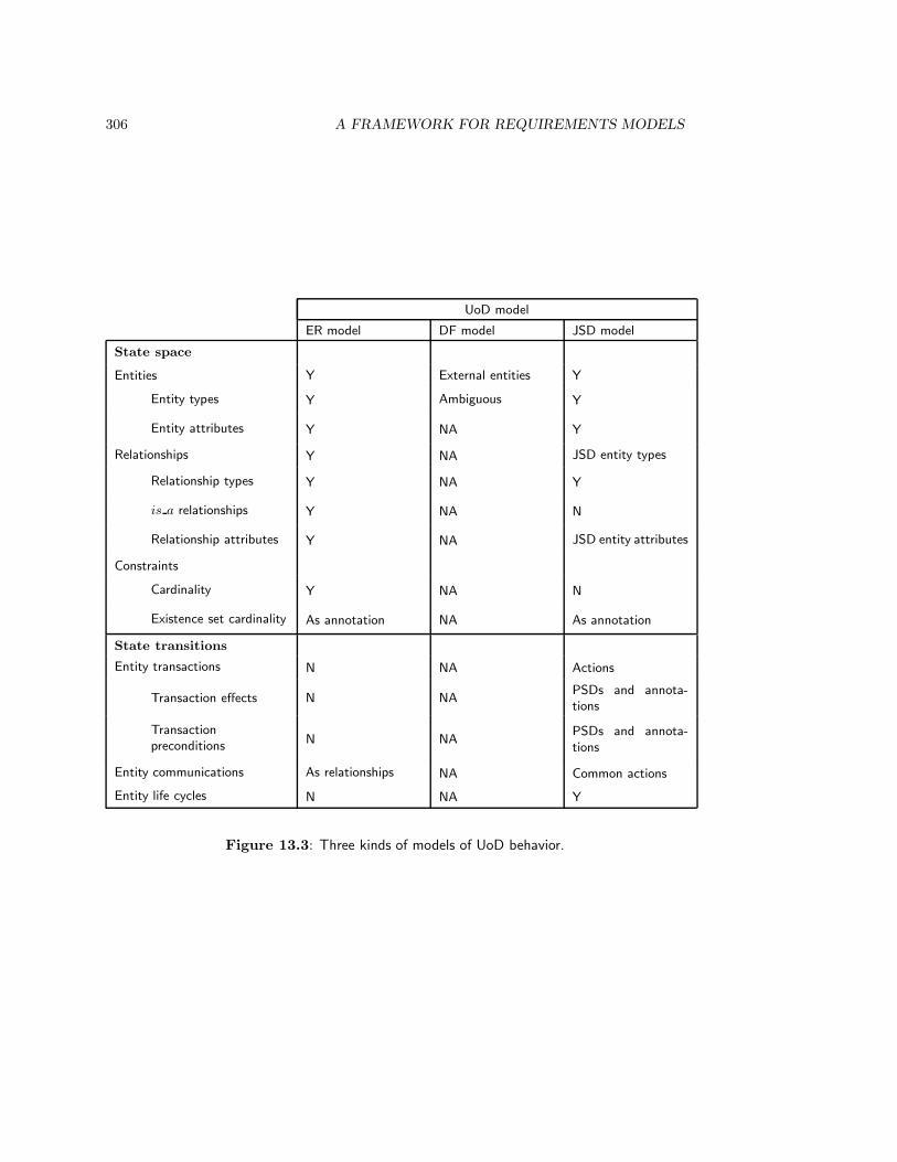
306 A FRAMEWORK FOR REQUIREMENTS MODELS
UoD model
ER model DF model JSD model
State space
Entities Y External entities Y
Entity types Y Ambiguous Y
Entity attributes Y NA Y
Relationships Y NA JSD entity types
Relationship types Y NA Y
is a relationships Y NA N
Relationship attributes Y NA JSD entity attributes
Constraints
Cardinality Y NA N
Existence set cardinality As annotation NA As annotation
State transitions
Entity transactions N NA Actions
Transaction effects N NAPSDs and annota-tions
Transactionpreconditions
N NAPSDs and annota-tions
Entity communications As relationships NA Common actions
Entity life cycles N NA Y
Figure 13.3: Three kinds of models of UoD behavior.

13.3. A FRAMEWORK FOR BEHAVIOR SPECIFICATIONS 307
• The ER notation does not allow the representation of behavior. In JSD, entity trans-actions (the smallest unit of interaction of an entity with its environment) are repre-sented by actions. For each action, preconditions and effects can be defined.
• UoD entities communicate in JSD by means of common actions. As will be ex-plained below, communications can end up in an ER model as relationships.
• Entity behavior is constrained in JSD by the definition of life cycles.
13.3.2 Models of system behavior
Figure 13.4 applies the framework to models of product behavior. It repeats the frameworkshown earlier in figure 11.23. Note that the framework can be applied to computer-basedsystems as well as to software systems. We collect here the remarks made in the method-ological analyses of the models produced by the ER approach, DF modeling and JSD.
• In each state of the system, a set of entities exist. These may be ER entities,data store records (DF), data stream records (JSD), surrogates that represent UoDentities (JSD), or the state of long-running function processes (JSD). Each existingentity, record, surrogate or long-running function process has a state, representedby attribute values (ER and JSD), field values (DF), or local variables of a functionprocess (JSD). In JSD, an additional part of the state of a surrogate or a long-runningfunction process is represented by a life cycle indicator.
• Relationships are represented as structured data stores in DF models and as surro-gates in JSD. Relationships may have attributes, and in ER models there are specialrelationships called is a to represent the taxonomic structure of entity types.
• A number of constraints can be defined for the system state. ER models restrictthe state space by means of cardinality constraints. Storage constraints, that limit thesize of the existence sets, can be specified in DF models as annotations of data storedefinitions in the data dictionary, and as annotations of entity types in JSD models.
• ER models do not represent system transactions. In DF models, system trans-actions can be represented by data transformations, but this is not enforced by thenotation. Preconditions and effects are specified as part of minispecs of data trans-formations. In JSD models, system transactions are represented as parts of inputfunctions, output functions and interactive functions. These functions may be embed-ded, in which case they are actions whose preconditions and effects can be specifiedas annotations to a PSD for a surrogate process. Functions may also be short orlong-running processes. A short-running process represents a single transaction, buta long-running process performs transactions on demand and continues to exist afterthe transaction has been executed. In either case, a transaction is represented by aPSD consisting of several actions, for which preconditions and effects can be specifiedas annotations to the PSD.
• DF models represent the system as a network of processes (i.e. data transformations)and data stores. Communication is through data flows. JSD models represent thesystem as a collection of (surrogate or function) processes that communicate throughdata streams, state vectors and controlled data streams.

308 A FRAMEWORK FOR REQUIREMENTS MODELS
System model
ER model DF model JSD model
State space
Entities Y Data store records
Surrogates,long-runningfunction processesdata stream records
Entity types Y Data stores
Surrogate types,long-runningfunctionsdata streams
Entity attributes Y Data store fields Y
Relationships YStructured datastores
Surrogate types
is a Relationships Y N N
Relationship types Y Data stores Surrogate types
Relationship attributes Y Data store fields Surrogate attributes
Constraints
Cardinality Y Data dictionary N
Storage constraints As annotation Data dictionary As annotation
State transitions
System transactions NDatatransformations
Function processes
Transaction effects N MinispecsPSDs and annota-tions
Transactionpreconditions
N MinispecsPSDs and annota-tions
Process communications N Data flows Process connections
Life cycles N In RT extensions PSDs
Other constraints
Interface technology N Data dictionary N
Response time N Data dictionary As annotations
Delay N Data dictionary As annotations
Figure 13.4: Three kinds of models of the SuD.
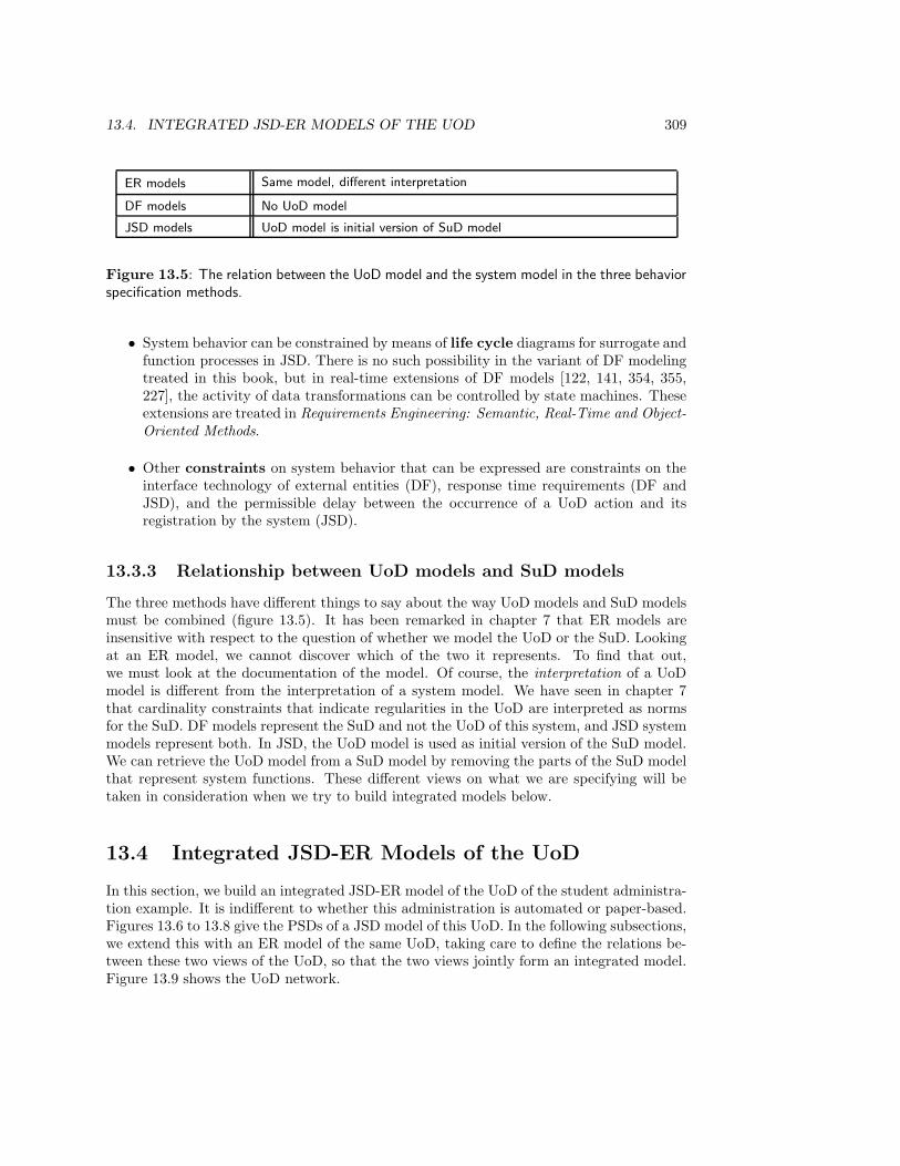
13.4. INTEGRATED JSD-ER MODELS OF THE UOD 309
ER models Same model, different interpretation
DF models No UoD model
JSD models UoD model is initial version of SuD model
Figure 13.5: The relation between the UoD model and the system model in the three behaviorspecification methods.
• System behavior can be constrained by means of life cycle diagrams for surrogate andfunction processes in JSD. There is no such possibility in the variant of DF modelingtreated in this book, but in real-time extensions of DF models [122, 141, 354, 355,227], the activity of data transformations can be controlled by state machines. Theseextensions are treated in Requirements Engineering: Semantic, Real-Time and Object-Oriented Methods.
• Other constraints on system behavior that can be expressed are constraints on theinterface technology of external entities (DF), response time requirements (DF andJSD), and the permissible delay between the occurrence of a UoD action and itsregistration by the system (JSD).
13.3.3 Relationship between UoD models and SuD models
The three methods have different things to say about the way UoD models and SuD modelsmust be combined (figure 13.5). It has been remarked in chapter 7 that ER models areinsensitive with respect to the question of whether we model the UoD or the SuD. Lookingat an ER model, we cannot discover which of the two it represents. To find that out,we must look at the documentation of the model. Of course, the interpretation of a UoDmodel is different from the interpretation of a system model. We have seen in chapter 7that cardinality constraints that indicate regularities in the UoD are interpreted as normsfor the SuD. DF models represent the SuD and not the UoD of this system, and JSD systemmodels represent both. In JSD, the UoD model is used as initial version of the SuD model.We can retrieve the UoD model from a SuD model by removing the parts of the SuD modelthat represent system functions. These different views on what we are specifying will betaken in consideration when we try to build integrated models below.
13.4 Integrated JSD-ER Models of the UoD
In this section, we build an integrated JSD-ER model of the UoD of the student administra-tion example. It is indifferent to whether this administration is automated or paper-based.Figures 13.6 to 13.8 give the PSDs of a JSD model of this UoD. In the following subsections,we extend this with an ER model of the same UoD, taking care to define the relations be-tween these two views of the UoD, so that the two views jointly form an integrated model.Figure 13.9 shows the UoD network.
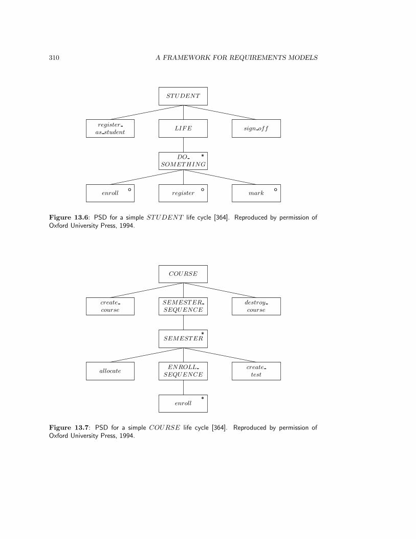
310 A FRAMEWORK FOR REQUIREMENTS MODELS
STUDENT
LIFEregister
as studentsign off
DO
SOMETHING
*
registero
enrollo
marko
Figure 13.6: PSD for a simple STUDENT life cycle [364]. Reproduced by permission ofOxford University Press, 1994.
COURSE
SEMESTER
SEQUENCE
create
course
destroy
course
SEMESTER*
ENROLL
SEQUENCEallocate
create
test
enroll*
Figure 13.7: PSD for a simple COURSE life cycle [364]. Reproduced by permission ofOxford University Press, 1994.
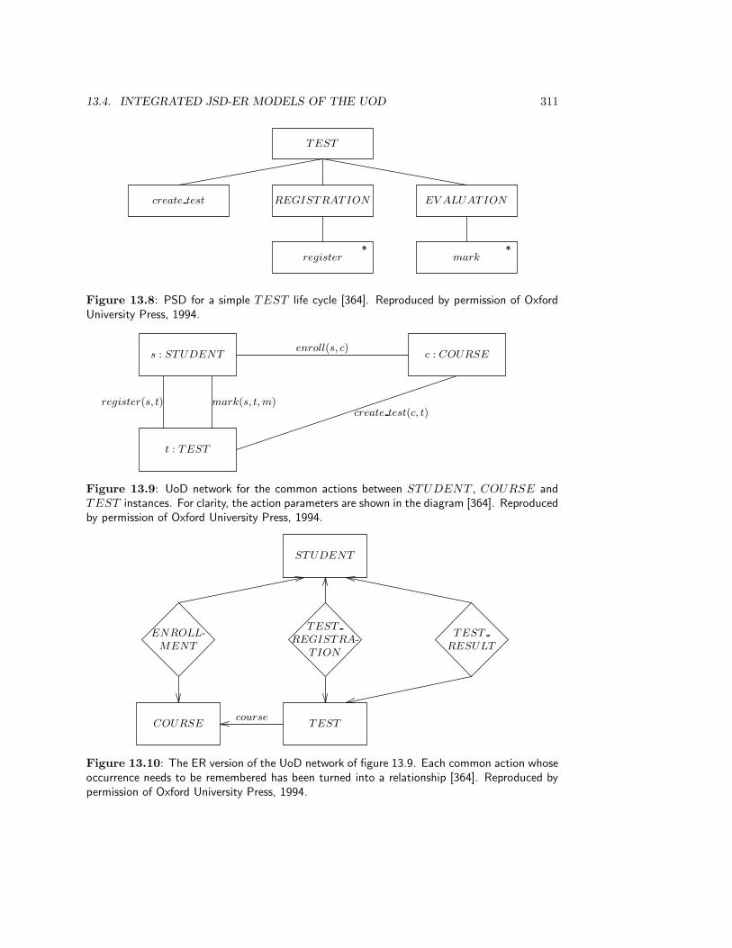
13.4. INTEGRATED JSD-ER MODELS OF THE UOD 311
TEST
REGISTRATIONcreate test EV ALUATION
register*
mark*
Figure 13.8: PSD for a simple TEST life cycle [364]. Reproduced by permission of OxfordUniversity Press, 1994.
s : STUDENT c : COURSE
t : TEST
enroll(s, c)
mark(s, t, m)register(s, t)create test(c, t)
Figure 13.9: UoD network for the common actions between STUDENT , COURSE andTEST instances. For clarity, the action parameters are shown in the diagram [364]. Reproducedby permission of Oxford University Press, 1994.
STUDENT
ENROLL-MENT
TEST
REGISTRA-TION
TEST
RESULT
COURSE TESTcourse
Figure 13.10: The ER version of the UoD network of figure 13.9. Each common action whoseoccurrence needs to be remembered has been turned into a relationship [364]. Reproduced bypermission of Oxford University Press, 1994.
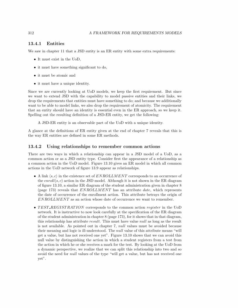
312 A FRAMEWORK FOR REQUIREMENTS MODELS
13.4.1 Entities
We saw in chapter 11 that a JSD entity is an ER entity with some extra requirements:
• It must exist in the UoD,
• it must have something significant to do,
• it must be atomic and
• it must have a unique identity.
Since we are currently looking at UoD models, we keep the first requirement. But sincewe want to extend JSD with the capability to model passive entities and their links, wedrop the requirements that entities must have something to do; and because we additionallywant to be able to model links, we also drop the requirement of atomicity. The requirementthat an entity should have an identity is essential even in the ER approach, so we keep it.Spelling out the resulting definition of a JSD-ER entity, we get the following:
A JSD-ER entity is an observable part of the UoD with a unique identity.
A glance at the definitions of ER entity given at the end of chapter 7 reveals that this isthe way ER entities are defined in some ER methods.
13.4.2 Using relationships to remember common actions
There are two ways in which a relationship can appear in a JSD model of a UoD, as acommon action or as a JSD entity type. Consider first the appearance of a relationship asa common action in the UoD model. Figure 13.10 gives an ER model in which all commonactions in the UoD network of figure 13.9 appear as relationships.
• A link 〈s, c〉 in the existence set of ENROLLMENT corresponds to an occurrence ofthe enroll(s, c) action in the JSD model. Although it is not shown in the ER diagramof figure 13.10, a similar ER diagram of the student administration given in chapter 8(page 173) reveals that ENROLLMENT has an attribute date, which representsthe date of occurrence of the enrollment action. This attribute betrays the origin ofENROLLMENT as an action whose date of occurrence we want to remember.
• TEST REGISTRATION corresponds to the common action register in the UoDnetwork. It is instructive to now look carefully at the specification of the ER diagramof the student administration in chapter 8 (page 173), for it shows that in that diagram,this relationship has attribute result. This must have value null as long as the resultis not available. As pointed out in chapter 7, null values must be avoided becausetheir meaning and logic is ill-understood. The null value of this attribute means “willget a value, but has not received one yet”. Figure 13.10 shows that we can avoid thisnull value by distinguishing the action in which a student registers from a test fromthe action in which he or she receives a mark for the test. By looking at the UoD froma dynamic perspective, we realize that we can split this relationship into two and soavoid the need for null values of the type “will get a value, but has not received oneyet”.
13.4. INTEGRATED JSD-ER MODELS OF THE UOD 313
• A link 〈s, t〉 in the existence set of TEST RESULT corresponds to the commonaction mark(s, t, m) in the UoD model. The link has the attribute result with valuem.
• The total many-one relationship course in the ER diagram corresponds to the create test
action in the JSD model. An occurrence of the create test(c, t) action correspondsto a function application course(t) = c. TEST is an entity type with dependentexistence, i.e. one whose instances are created by another entity in the model, i.c.COURSE. Because a course can create many tests, and each test is always created byexactly one course, the relationship from TEST to COURSE is a total function. Thisholds in general for the relationship between an entity type with dependent existenceand the entity type upon whom its existence depends.
The guideline to be extracted from this is that if a relationship corresponds to a commonaction, then the components of the relationship are the identifiers of the objects that sharethe common action. The other action parameters end up as attributes of the relationship.
What is common in the above examples is that the common actions all need to be remem-bered by the system. The second guideline to be extracted from the example is thereforethat common actions in a JSD model of the UoD must be represented as relationships in theER model of the UoD if the system must remember their occurrence; otherwise, they neednot be represented as a relationship in the ER model. For example, if an elevator and anelevator motor share the actions start and stop, this need not give rise to two relationshipsbetween the ELEV ATOR and the MOTOR entity types, because there is no databasethat must remember which start or stop events occurred.
Note also that there may be other relationships in an ER model that do not correspond tocommon actions in a JSD model of that UoD. Relationships can stand for part-of relations,element-of relations, contractual obligations, permissions, authorizations, etc. These arenot normally viewed as common actions.
Two advantages of defining relationships that correspond to common actions are thatit allows us to specify which action occurrences must be remembered by the system, andconversely that it allows us to represent the meaning of some relationships more accurately.A third advantage is that it allows us to add cardinality information to the UoD model.For example, by translating the create test(c, t) action into a total many-one relationship(the course arrow), we made explicit the information that create test(c, t) can only beperformed once per test but can be performed many times per course. This information isnot represented explicitly in the JSD model. Similarly, the TEST RESULT relationshipadds cardinality information. In the JSD model, one student can receive several marks forone test. In the ER diagram, by contrast, each TEST RESULT instance is a relationshipbetween a student s and a test t, and for each pair 〈s, t〉 there is at most one such relationshipin TEST RESULT .
13.4.3 Reducing common actions by adding relationships
Relationships can also correspond to JSD entities in the JSD model. For example, in the ERmodel of the library given in chapter 8, LOAN is a relationship between MEMBER andDOCUMENT . In the JSD model of the same library given in chapter 12, we encounterLOAN as a JSD entity with its own life cycle. This can be explained as follows. The LOAN
life cycle contains, among others, the actions borrow, return, renew, and lose. On the face

314 A FRAMEWORK FOR REQUIREMENTS MODELS
t1 t2 t3 t4 t5 t6 · · ·E1
E2
E3
E4 C· · ·
Figure 13.11: The transaction decomposition table of a system. The horizontal dimensionrepresents all transactions of the system, the vertical dimension represents all types of whichthe system contains instances.
of it, these are all common actions shared by a member and a document. However, bymodeling LOAN as a JSD entity type, we are able to allocate these actions and attributesto LOAN only and need not allocate them to MEMBER or DOCUMENT . The combinedJSD-ER model more accurately represents what is happening, for in the ER model LOAN isa relationship between these two entity types. The JSD-ER model therefore represents thefact that all LOAN actions are shared by MEMBER and DOCUMENT , because theyoccur in the life of a link between a MEMBER and a DOCUMENT . Shared actions ofMEMBER and DOCUMENT are allocated to LOAN only, just as shared attributes areallocated to LOAN only without loss of information.
The guideline to be extracted from this example is that we can reduce the number ofentity types that share actions by introducing relationships to which the shared actionsare allocated. Of course, the allocation of actions to entity types in the JSD model shouldstill follow the heuristics for action allocation defined for JSD (figure 11.18). For example,if borrow increases an attribute of DOCUMENT that counts the number of times thedocument is borrowed, then borrow should be allocated to both LOAN and DOCUMENT .
13.4.4 The transaction decomposition table
ER models and JSD models of the UoD can be found by building a transaction decomposi-tion table (figure 13.11). In a UoD model, the horizontal dimension represents all observabletransactions of the UoD. If the SuD is a database system, then these are the actions in theUoD that must be registered by the database. If the SuD is a control system, then theseare actions in the UoD that must be registered by the system as well as actions in the UoDthat the system causes to occur. The vertical dimension represents all types of which theUoD contains instances. These are all the ER entity types and relationships. The entries ofthe table represent local actions in the life of instances, and the columns represent commonactions.
Suppose that transaction ti is a communication. If we want to remember the occurrencesof this transaction, then we must add a relationship that corresponds this common actionand add a “C” in the corresponding entry of the table. For example, each relationship E4
in figure 13.11 remembers the occurrence of transaction t1. If we then want to reduce thenumber of communications in the model then we can try to remove any other local eventsin the transaction according to the guidelines given above.
13.5. INTEGRATED JSD-ER-DF MODELS OF A SYSTEM 315
13.5 Integrated JSD-ER-DF Models of a System
It makes no sense to try to integrate a DF model of a computer-based system with a JSD-ER model of the UoD of that system, for the two models represent different systems. Wetherefore follow JSD and view the JSD-ER model of the UoD as an initial system model,which describes how the system models the UoD. In this section we extend this to anintegrated JSD-ER-DF initial system model. Since the JSD network and the DF notationfor system functions are so similar, further extension of an integrated initial model with aspecification of required system functions should be done by using either the JSD notationor the DF notation for the representation of system functions.
13.5.1 A JSD-ER-DF initial system model
In chapter 9, we presented an integrated DF and ER modeling method in which, as a firstapproximation guideline, each entity type and each relation in the ER model correspondsto a data store in the DF model. This guideline can be overruled by considerations ofmodularity, which cause us to join or split data stores in order to minimize or otherwisemodularize the access to data stores by data transformations. However, whatever is theresult of splitting and merging data stores, it must satisfy the rule that the structure of alldata in all data stores is described by the ER diagram, and that the ER diagram describesno other data than that in the data stores. This gives us one guideline to extend the JSD-ER model with a DF-ER model: the ER part of both models should be the same. This ERmodel gives us a single representation of the state space of the initial system.
Turning to behavior, the common denominator of the JSD part and the DF part ofan integrated model lies in the fact that they both represent system transactions. In theinitial JSD system model, the system is represented as consisting of a set of communicatingprocesses, where each process is a surrogate for a UoD entity. A system transaction is thenan update in the life of one surrogate corresponding to an action in the life of a UoD entity,or it is an update of a set of surrogates that corresponds to a common action in the life of aset of UoD entities. In either case, we abstract from the initiative of the transaction, whichcan lie with the UoD or with time (in the case of temporal transactions). In a JSD modelwe also abstract from the flow of data from the UoD to the system or back. The DF model,by contrast, represents a transaction as triggered by the arrival of one or more data flows atthe system, or by the occurrence of a temporal event (which is not shown in a DF diagram).The DF model describes the transaction by specifying the data transformations that leadto a change of state of the system and/or to the production of output by the system, whichit sends to one or more output data flows.
In order to represent transactions in a DF model, we have to show where their inputdata come from and where their output data goes to. This information is not representedby a JSD-ER model of the UoD nor in an initial JSD-ER system model. However, someexternal entities in a DF model may correspond to ER entity types.
Taking all these considerations together, we have the following guidelines for relatingthe initial JSD-ER and DF views of the system:
• The ER entity types and relationships jointly describe all and only the structure ofthe data stores. In the simplest case, there is one data store for each entity typeand relationship, and for each data store there is one entity type or relationship. Toexpress this, a data store should have the plural of the name of the entity type (e.g.

316 A FRAMEWORK FOR REQUIREMENTS MODELS
data store STUDENTS for the entity type STUDENT ). Still in the simplest case,each data store contains the existence set of its corresponding entity type, and eachrecord in the store is a surrogate for a UoD entity. In more complicated cases, datastores could have been split or merged.
• Each action in the JSD model corresponds to a DF fragment that accepts the inputdata of the action, updates data stores, and produces output. In the simplest case,an action occurring in the life of an entity of type E corresponds to exactly onedata transformation, which updates the data store corresponding to E. A commonaction could update the data stores corresponding to all entity types that share theaction. The data transformation may have to read other data stores in order to checkpreconditions for the action. In more complicated cases, a (possibly common) actioncould have been represented by a DF diagram fragment containing more than onedata transformation. However, even in this case, this fragment can be represented bya single data transformation, decomposed into a lower level DF diagram.
• Some external entities in the DF model would correspond to some entity types inthe JSD-ER model. These external entities should be given the same name as theircorresponding entity type (as a side effect, this makes clear that they are types ratherthan instances). Other external entities will not appear in the JSD or ER parts of themodel.
Figure 13.12 illustrates these guidelines by adding a DF diagram to our initial JSD-ERmodel. The USER is a person in the student administration department that uses theadministrative system. Each data store corresponds to one entity type or to a relationshipin the ER model of the system and each data transformation corresponds to a single actionin the initial JSD model of the system. A transformation reads from those data stores thatit needs for checking the action preconditions, and it writes to data stores that containa surrogate whose state it must change. A full DF model would additionally contain adata dictionary describing all data residing or flowing through the system, and minispecsspecifying the behavior of the primitive transformations (which all correspond to actions inour example). The DF model thus adds the following information to the JSD-ER model:
• It specifies the preconditions and effects of each action by means of data transforma-tions and their minispecs.
• It describes the data flowing between the system and its environment in each trans-action.
• It specifies with which external entities the system interfaces.
Conversely, the JSD part of the model adds life cycle information and provides a principlefor partitioning the activity of the system into transformations that correspond to entityactions or entity communications.
13.5.2 A JSD-ER-DF model of system functions
The system network in JSD and the DF diagram of a DF model both represent the systemas a network of communicating processes. The similarity between these two notations issufficiently large to regard them as alternative ways to model system functions, rather than

13.5. INTEGRATED JSD-ER-DF MODELS OF A SYSTEM 317
USER
create
course
destroy
courseallocate
create
testmark
COURSES TESTS STUDENTS
TEST RESULTS
sign offregister
as studentregister
STUDENT
enroll
ENROLLMENTSTEST
REGISTRATIONS
Figure 13.12: DF diagram belonging to an integrated JSD-ER-DF initial model of the studentadministration [364]. Reproduced by permission of Oxford University Press, 1994.

318 A FRAMEWORK FOR REQUIREMENTS MODELS
as supplementary ways. This means that in an integrated model, we should choose eitherone of these representations but not mix them.
Consider the JSD system network for the student administration given in figure 13.13and the DF diagram of the same functions shown in figure 13.14. Both models representtwo output functions, one to produce a list of individual student results upon request, andanother one to produce, upon request, a list of participants in a test.
In the JSD network, LIST RESULTS scans the existence set of STUDENT by meansof a state vector connection. The initiative of this connection lies with the receiver ofinformation (LIST RESULTS). LIST RESULTS is a long-running function process,and one instance of LIST RESULTS can scan the state of many STUDENT instances.In the DF model, List results is a data transformation that receives a request, reads a datastore, and produces output. In JSD terms, List results is a long-running function because,after it has produced output data, it is always ready to be activated by a new arrival ofinput data.
In the JSD network, LIST PARTICIPANTS is a short-running function that, wheninstantiated, empties a data stream D and reads STUDENT instances in order to print theappropriate information. The data stream is filled because TEST instances write register
actions to it every time a student registers for a test.There are a number of differences between these representations. We review these here
in the context of an integrated JSD-ER-DF model.
• The nodes in a DF diagram are data transformations or stores, the nodes in a JSDsystem network are surrogate types, function processes or data streams (figure 13.15).A data transformation in an integrated JSD-ER-DF model corresponds to an action inthe life of a surrogate or to an atomic system function. A data store in an integratedmodel corresponds to the existence set of an entity type (e.g. STUDENT ) or to adata stream (e.g. D corresponds to TEST REGISTRATIONS). In the data store,the sequencing information inherent in the data stream (which is a queue) is notrepresented, unless a record field is added that holds the date and time at which therecord was created.
• The nodes in a JSD network are types (whose instances are surrogates or functionprocesses). LIST RESULTS is a type with only one instance (the long-runningfunction with the same name). The nodes in a data flow diagram are all individuals,viz. transformations or data stores. Because of this, the JSD network can show thecardinality of process connections, telling us how many instances of one node maybe connected to how many instances of another node. A data flow model cannotshow cardinalities other than the implicit one-one connection between individuals,represented by data flows.
• The function processes in a JSD network are all represented in the same way, viz.by means of PSDs. In a DF model, they can be represented by minispecs, using anyspecification language, or by lower level DF diagrams. In particular, a DF modelallows declarative function specification by means of pre- and postconditions.
• There are three kinds of process connections in a JSD system network (state vector,data stream, controlled data stream) and there is only one kind of connection in aDF model (data flow). However, distinguishing different kinds of process connections
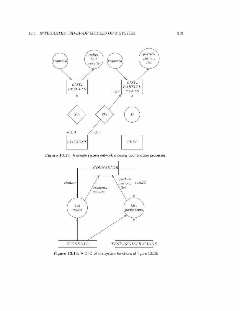
13.5. INTEGRATED JSD-ER-DF MODELS OF A SYSTEM 319
STUDENT
n ≥ 0
SV1
LIST
RESULTS
indivi-dual
resultsrequest i
LIST
PARTICI-PANTS
SV2
n ≥ 0
n ≥ 0
partici-pation
listrequest t
D
TEST
Figure 13.13: A simple system network showing two function processes.
Listresults
COUNSELOR
stud nr
student
results
STUDENTS
Listparticipants
TEST REGISTRATIONS
test idpartici-pation
list
Figure 13.14: A DFD of the system functions of figure 13.13.
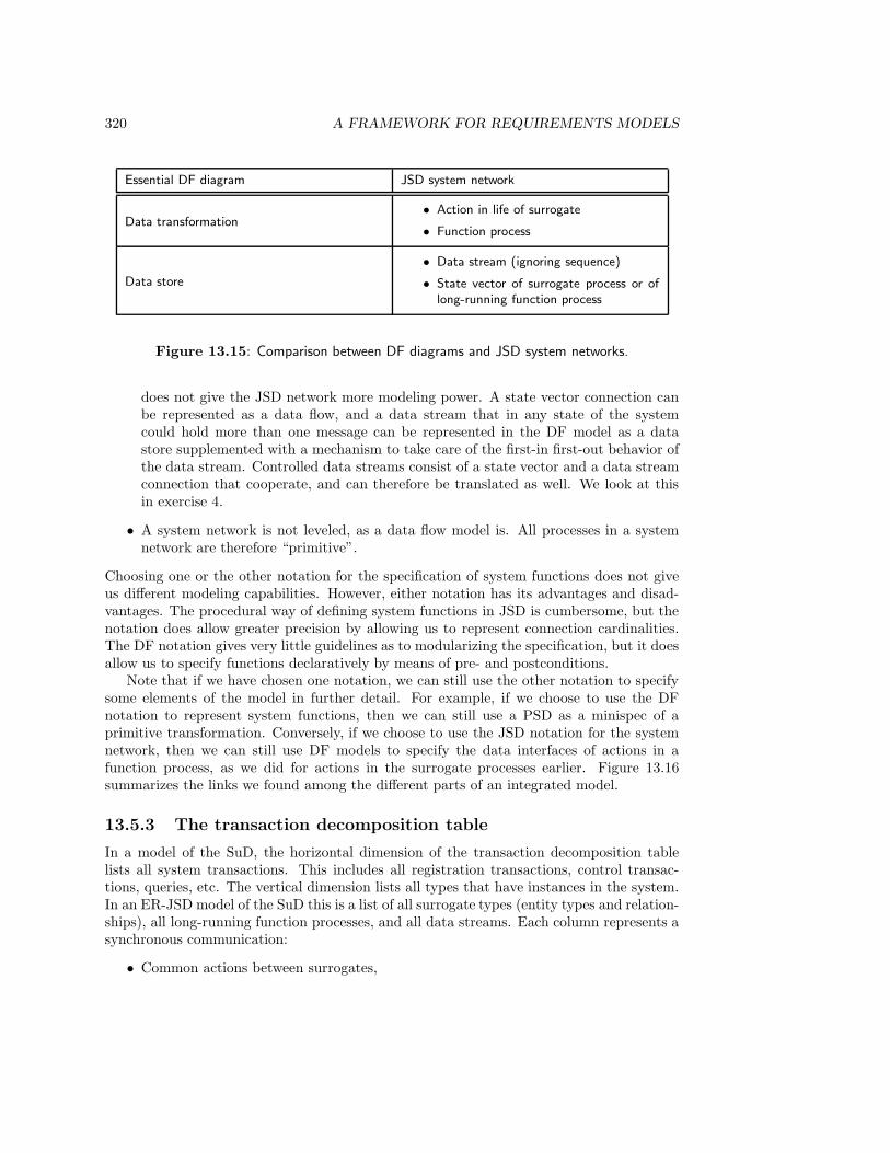
320 A FRAMEWORK FOR REQUIREMENTS MODELS
Essential DF diagram JSD system network
Data transformation• Action in life of surrogate
• Function process
Data store
• Data stream (ignoring sequence)
• State vector of surrogate process or oflong-running function process
Figure 13.15: Comparison between DF diagrams and JSD system networks.
does not give the JSD network more modeling power. A state vector connection canbe represented as a data flow, and a data stream that in any state of the systemcould hold more than one message can be represented in the DF model as a datastore supplemented with a mechanism to take care of the first-in first-out behavior ofthe data stream. Controlled data streams consist of a state vector and a data streamconnection that cooperate, and can therefore be translated as well. We look at thisin exercise 4.
• A system network is not leveled, as a data flow model is. All processes in a systemnetwork are therefore “primitive”.
Choosing one or the other notation for the specification of system functions does not giveus different modeling capabilities. However, either notation has its advantages and disad-vantages. The procedural way of defining system functions in JSD is cumbersome, but thenotation does allow greater precision by allowing us to represent connection cardinalities.The DF notation gives very little guidelines as to modularizing the specification, but it doesallow us to specify functions declaratively by means of pre- and postconditions.
Note that if we have chosen one notation, we can still use the other notation to specifysome elements of the model in further detail. For example, if we choose to use the DFnotation to represent system functions, then we can still use a PSD as a minispec of aprimitive transformation. Conversely, if we choose to use the JSD notation for the systemnetwork, then we can still use DF models to specify the data interfaces of actions in afunction process, as we did for actions in the surrogate processes earlier. Figure 13.16summarizes the links we found among the different parts of an integrated model.
13.5.3 The transaction decomposition table
In a model of the SuD, the horizontal dimension of the transaction decomposition tablelists all system transactions. This includes all registration transactions, control transac-tions, queries, etc. The vertical dimension lists all types that have instances in the system.In an ER-JSD model of the SuD this is a list of all surrogate types (entity types and relation-ships), all long-running function processes, and all data streams. Each column represents asynchronous communication:
• Common actions between surrogates,
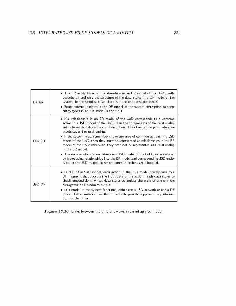
13.5. INTEGRATED JSD-ER-DF MODELS OF A SYSTEM 321
DF-ER
• The ER entity types and relationships in an ER model of the UoD jointlydescribe all and only the structure of the data stores in a DF model of thesystem. In the simplest case, there is a one-one correspondence.
• Some external entities in the DF model of the system correspond to someentity types in an ER model in the UoD.
ER-JSD
• If a relationship in an ER model of the UoD corresponds to a commonaction in a JSD model of the UoD, then the components of the relationshipentity types that share the common action. The other action parameters areattributes of the relationship.
• If the system must remember the occurrence of common actions in a JSDmodel of the UoD, then they must be represented as relationships in the ERmodel of the UoD; otherwise, they need not be represented as a relationshipin the ER model.
• The number of communications in a JSD model of the UoD can be reducedby introducing relationships into the ER model and corresponding JSD entitytypes in the JSD model, to which common actions are allocated.
JSD-DF
• In the initial SuD model, each action in the JSD model corresponds to aDF fragment that accepts the input data of the action, reads data stores tocheck preconditions, writes data stores to update the state of one or moresurrogates, and produces output.
• In a model of the system functions, either use a JSD network or use a DFmodel. Either notation can then be used to provide supplementary informa-tion for the other.
Figure 13.16: Links between the different views in an integrated model.

322 A FRAMEWORK FOR REQUIREMENTS MODELS
• state vector access by a function process,
• sending data to a data stream or receiving data from a data stream,
• communicating through a controlled data stream.
In a DF model of the SuD, the vertical dimension of the table is a list of all data stores andeach column corresponds to a DF diagram fragment.
13.6 Modularization Principles
In this section, we look at different modularization principles used for behavior specificationsin JSD and DF modeling.
13.6.1 Object-oriented and Von Neumann modularization
JSD and DF modeling both use modularization principles to partition the behavior specifi-cation into digestible chunks. This is not the same as decomposing the specified system intosubsystems, i.e. descending in the aggregation hierarchy of systems. The decompositionof a behavior specification into specification modules stays at one level of the aggregationhierarchy. JSD and DF modeling use different modularization principles for partitioningthe specification:
• DF models use the Von Neumann modularization principle that separates com-ponents that process data but do not remember data, from components that rememberdata but do not process data. This is a natural modularization principle in manualadministrations, where people do the processing and paper provides the memory, andfor computing systems that separate programs from files.
• JSD models use an object-oriented modularization principle, in which processingand memory are encapsulated into units that can perform their tasks in parallel. UoDentities, surrogate processes, and function processes all follow this principle.
The difference can be easily expressed in terms of the transformation decomposition table:in object-oriented modularization, each row of the transaction decomposition table is en-capsulated in the life cycle of the surrogate type or long-running function. (Data streamshave a simple life cycle that iterates over addition of items to a queue and removal of itemsfrom a queue.) In Von Neumann modularization, rows and columns are separated. In es-sential system models, each column corresponds to a single data transformation and eachrow corresponds to a data store.
One consequence of this difference is that a DF model does not contain any sequencinginformation. The DF model in figure 13.12 only shows which data transformations aretriggered as a result of the arrival of some input, which data stores they access, and wherethey send their output. This is precisely the intention of a DF model, viz. to show whichtransformations and data stores must be realized by a system, and what their interfacesare if the system is to perform its function. All information about sequencing of datatransformations has been eliminated. The JSD model, by contrast, allows the encapsulationof activity and memory into its models of UoD entities, and it is natural in this view tospecify constraints on the sequencing of activity, i.e. to specify life cycles for UoD entities.
13.6. MODULARIZATION PRINCIPLES 323
A related consequence is that the interfaces shown in a DF model are data flows, whereasthe interfaces shown in a JSD model of the UoD are common actions. The separation ofactivity and memory in the Von Neumann modularization forces us to use data flows asinterfaces. Since data stores have no activity, their interface will not consist of other actionsoperations that read and write data. By contrast, encapsulation of activity and memoryinto models of UoD entities allows the specification of interfaces by means of shared actions.Of course, in an integrated model, a DF diagram with accompanying minispecs may still beused to specify preconditions and effects of actions in a PSD. For example, the DF diagramcan show what must be done when the precondition is not satisfied.
Separation of activity from storage adds interfaces to a diagram for another reasonas well. Some data flows will show a read access of a transformation to a data store toretrieve information that it has itself put there earlier (cf. section 5.4). These interfaceswill be removed in an object-oriented modularization. The remaining interfaces are essentialcommunications between objects.
In chapter 12, we briefly described a simple way to implement JSD models of a system. Inthe implementation task, we descend in the aggregation hierarchy. One element of the JSDimplementation method is the separation of state vectors of surrogate processes and long-running functions from the specification of the actions in these processes, and store thesestate vectors in files or global variables. This corresponds to a move from object-orientedmodularization for a software behavior specification to a Von Neumann modularization forthe software system implementation. In a specification of required external behavior of adata manipulation system, it is natural to imagine that each object has its own dedicatedprocessor with its own unrestricted memory, whereas in an implementation of the systemit is more natural if we view the system as a collection of processes that interface witha passive memory, that is shared by some processes. This means that in Von Neumannmodularization, much care must be taken to avoid inadvertent access to the wrong statevectors. As remarked by Booch [44], in Von Neumann modularization any state vector in astore is globally accessible to any data transformation that accesses the store.
13.6.2 UoD-oriented modularization
There is a further difference between the modularizations followed by JSD and StructuredAnalysis, which is to do with the fact that JSD distinguishes a UoD model from a systemmodel, whereas Structured Analysis recognizes only a system model. This means thatthere is a modularization principle available in JSD that is not available in StructuredAnalysis: partition the system into surrogates that correspond to UoD entities. Let us callthis UoD-oriented modularization. Although the UoD can be a very chaotic place,it is still a useful place to look for help in defining natural boundaries between differentcomponents of our requirements specification. If we manage to find useful chunks in ourrequirements model that correspond to chunks in the UoD, then we have a requirementsmodel that is more easily communicable to people who know a lot about the UoD, becausethe terminology with which we talk about the system requirements corresponds more closelyto the terminology with which domain specialists talk about the UoD. As a consequence,validation of the model with engineers, working on systems in the UoD, or with users whohave domain knowledge of the UoD, is facilitated.
In addition to leading to more understandable requirements models, UoD-oriented mod-ularization leads to more maintainable requirements models because they are as stable as
324 A FRAMEWORK FOR REQUIREMENTS MODELS
the UoD is. Usually, the UoD is more stable than the desires of the customers and users.A requirements model that is partioned into a UoD model and a system function modeltherefore consists of at least one part that is stable. The more variable part, the functionmodel, can be defined in terms of this more stable one. And if the requirements model ismore maintainable, the system is likely to be more maintainable too.
These advantages of structuring requirements models have already been pointed out atthe end of chapter 11, as they belong to the motivations that Jackson gives for his approachto requirements specifications. Here, we add another argument, based on the specificationof reactive systems. A reactive system was defined in section 9.6 as a system whose responseto an input depends on the current input as well as on the past history of inputs, and acombinational system was defined as a system whose response to an input depends onlyupon the current input. The behavior of a combinational system system can be specifiedby a mathematical function, whereas the behavior of a reactive system must be specifiedby more complex means such as a state transition diagram or a PSD. DF diagrams are nota good way to specify the behavior of complex reactive systems, because all that is shownby the diagram is the data flow interfaces of each data transformation. In an essential DFmodel, these are the data interfaces of each transaction. The dependence of system behavioron past inputs is hidden in the minispecs and in the data store accesses.
The functional primitives in a DF diagram hierarchy are combinational systems, becausethey have no internal state that remembers previous inputs — all history is remembered bydata stores. For the same reason, a transformation that remembers past inputs in a localdata store such that the contents of this store determines the response to current inputs, isreactive. The JSD entities in a UoD model are also reactive systems, because they have alocal state that remembers (part of) their history and that determines their possible futurebehavior.
In general, the behavior of a reactive system is harder to understand than that ofcombinational systems, because the effect of an input on the system depends upon the localstate of the system. Consider the Borrow data transformation in figure 13.17, which hasa local data store that determines part of its behavior, and is therefore a reactive system.Upon reception of a request for borrowing a document, the Check transformation looks at acondition on the data store DOCUMENTS, say the total number of documents currentlyborrowed. If this number is too high, the borrow request is refused, otherwise it is grantedand the data store is updated accordingly. Note that this logic is not visible from the dataflow diagram; it must be written down in minispecs. The response to a borrow requestin this example depends in an obscure way on the local state of the data transformation,and this makes the effect of the transformation hard to understand. Contrast this witha functional transformation like Update Documents in the same diagram, which does thesame thing every time it is activated.
Figure 13.18 specifies another reactive transformation, corresponding to a UoD object.The transformation contains a local data store that holds the state vectors of all existingstudent surrogates and of some local data transformations, each corresponding to one actionin the life of a student surrogate. Because the transformation has a local data store, it isa reactive system, but because it corresponds to a UoD entity, its behavior is as easy tounderstand as that of the corresponding UoD entity. UoD-oriented modularization thusallows us to find reactive systems with a behavior that is more understandable than withanother kind of modularization.
In terms of the modularity heuristics given in figure 2.1, UoD-oriented modularization
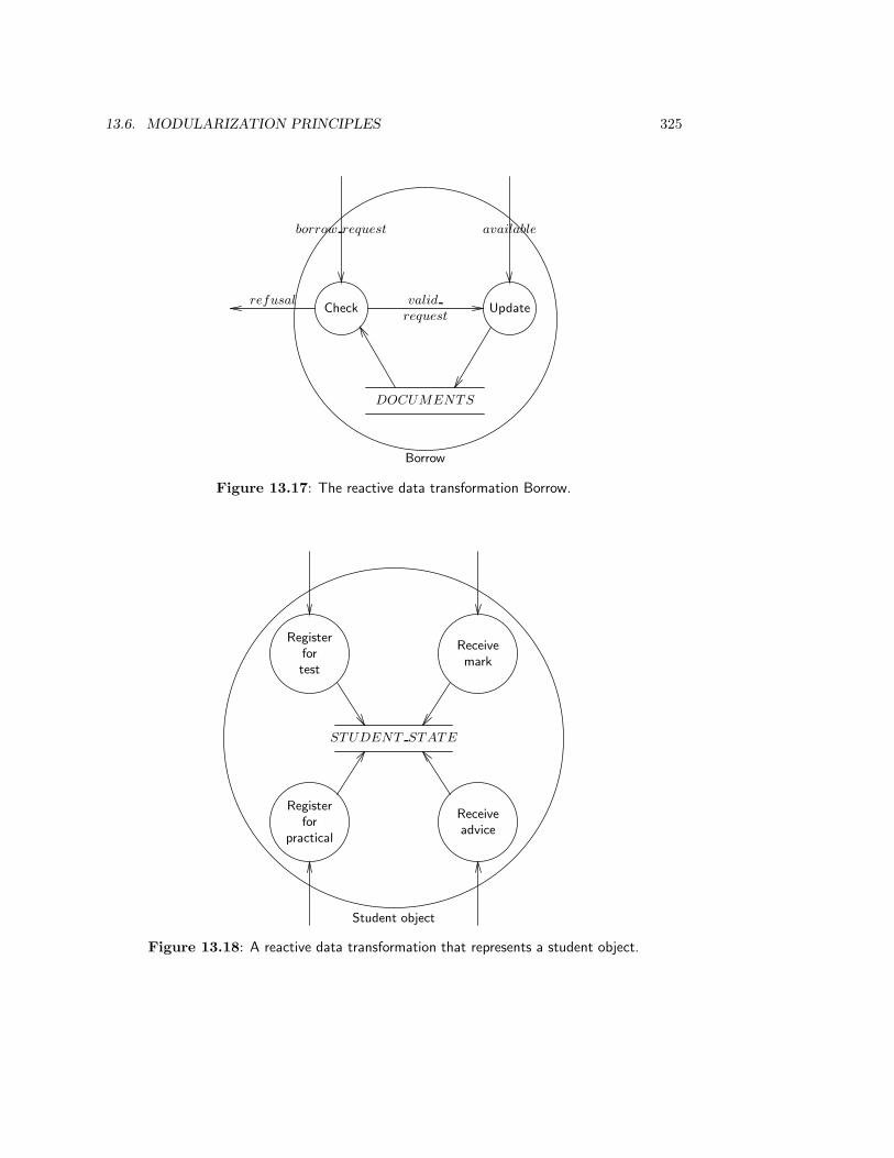
13.6. MODULARIZATION PRINCIPLES 325
DOCUMENTS
Check
borrow request
refusalUpdate
available
Borrow
valid
request
Figure 13.17: The reactive data transformation Borrow.
STUDENT STATE
Registerfortest
Receivemark
Registerfor
practical
Receiveadvice
Student object
Figure 13.18: A reactive data transformation that represents a student object.

326 A FRAMEWORK FOR REQUIREMENTS MODELS
Product idea
t1 t2 t3 t4 t5 t6 · · ·E1
E2
E3
E4
· · ·
Figure 13.19: Linking the transaction decomposition table to the function decomposition treeof the product.
leads to modules in a requirements specification that have an underlying system idea. Interms of structured design guidelines, reactive systems that represent real world entitieshave the maximal degree of cohesion, viz. functional cohesion [251, 325]. According to theseguidelines, JSD models thus have the best kind of modularity. Note that the cohesiveness ofmodules remains high when we go to the system network in JSD, for we then add processesthat represent product functions. These processes have a clear intuitive semantics in terms ofrequired system functions. In fact, the concept of functional cohesion is originally motivatedby the high cohesion that system functions have.
13.7 Integrating System Models with Environment Mod-
els
The environment of a computer-based system is a social system which has been modeled invarious ways in ISAC change analysis and in IE information strategy planning. A simplebut powerful organization model used in information strategy planning is the function de-composition tree. Figure 13.19 shows that we can link the transaction decomposition tableto a function decomposition tree that decomposes the product idea into atomic transactionsrequired of the product. This connects the transaction decomposition table to the servicethat the system must provide to its environment.
In Structured Analysis, function decomposition is continued below the level of observablesoftware system transactions down to the level of functional primitives. Figure 13.19 showsthat at the point where we reach system transactions, we may, as an alternative, continuewith object-oriented modularization.
In ISAC, we build a hierarchy of activity models with a diagram notation that hasvirtually the same semantics as DF models. Just like DF models, activity models areorganized in a tree. They are used to model activities in an organization and not necessarilythe activities of a computer-based system. Nevertheless, the transactions of a computer-based system are transactions with its social environment. If these transactions have any use
13.8. SUMMARY 327
for the social environment, then they will also appear as leaves in a function decomposition ofthis environment. In other words, they will appear in the leaves of the hierarchy of businessactivity models made in ISAC change analysis. Thus, some internal business transactionswill appear in a function decomposition tree of a business information system, in a functiondecomposition tree of the business itself, and as atomic activities in an ISAC activity modelof the business.
13.8 Summary
A method for modeling system behavior should provide concepts to describe the system statespace and concepts to describe the state transitions of the system. This holds for methodsto model the UoD as well as methods to model computer-based systems. Our framework forUoD models distinguishes entity types, relationships, attributes and state space constraintsas concepts to look for in a state space description, and transactions, communications andlife cycles as concepts to look for in state transition descriptions. Examples of state spaceconstraints are cardinality constraints on links and constraints on existence set cardinality.Our framework for system models lists similar concepts, and adds behavior constraints suchas data rates, interface requirements, response time constraints and delay constraints.
An ER model of the UoD is also an ER model of the system, DF models represent datamanipulation systems but not the UoD of such systems, and JSD uses the UoD model asthe initial version of a system model.
If we build an integrated ER-JSD model of a UoD, then we can use relationships torepresent communications that must be remembered by the system. Relationships canadditionally be used to reduce the number of communications in a model by allocatingcommon actions to them. An integrated JSD-ER-DF initial system model extends a JSD-ER initial system model with DF models of transactions. DF diagram fragments can beused to specify preconditions and effects of transactions. In an integrated specification ofsystem functions, we must choose either JSD’s system network notation or the DF notation;the two cannot be mixed in the specification of system functions. However, if we choose theJSD notation, we can use DF diagram fragments to specify actions; and if we choose theDF notation, we can use PSDs as minispecs of primitive data transformations.
Analysis of the modularization principles used in DF modeling and in JSD reveals thefollowing two differences:
• In JSD object-oriented modularization is used, and in DF modeling Von Neumannmodularization is used.
• JSD uses a UoD-oriented heuristic for modularization.
Because DF models are intended to show data interfaces and no control, all sequencing infor-mation is lost in a DF model and all interfaces as data flows. In JSD, sequencing of actionsis represented (by PSDs) and all interfaces are actions. The Von Neumann modularizationof DF models appears in the JSD method when we move to implementation. The transac-tion decomposition table is partitioned horizontally by object-oriented modularization andvertically by Von Neumann modularization.
The UoD-oriented heuristic to identify specification modules generally leads to a moreunderstandable and maintainable partitioning of the specification, because this partitioning

328 A FRAMEWORK FOR REQUIREMENTS MODELS
corresponds to the UoD and the UoD is usually more stable than required system functions.This leads to a high form of cohesion of the specification modules, called functional cohesionin Structured Design.
The transaction decomposition table can be linked to a function decomposition tree ofthe product idea as well as to a function decomposition tree of the business mission. Thislinks the transaction decomposition table, and hence an integrated system model, to higherlevel models of the social environment
13.9 Exercises
1. This exercise is about the model of deliverables of Change Analysis and ISP in fig-ure 13.1.
(a) Add cardinalities to the model.
(b) Add the subject areas PRODUCT OBJECTIV ES and PRODUCT ENV I-RONMENT .
2. In the JSD model of the UoD of the student administration of section 13.4, eachstudent can receive multiple marks for a test. Prove this by constructing a trace ofactions generated by the JSD model in which one student receives two marks for thesame test in a row.
3. In subsection 13.4.3, we allocated borrow to LOAN only. Check that this conformsto the action allocation heuristics of figure 12.3.
4. (a) Build a DF model that simulates the behavior of a data stream.
(b) Build a DF model that simulates the behavior of a controlled data stream.
Discuss the accuracy of these simulations.
5. The solutions of the library case study given in this book are part of an integratedJSD-ER-DFD model of the circulation desk.
(a) Show that the ER model of chapter 8 and the JSD model of chapter 12 can becombined so that they are part of one integrated ER–JSD model of the UoD ofthe circulation desk. Which additions would be needed to complete the model?
(b) Show that the DF solution given in chapter 10 extends this model of the UoD ofthe circulation desk.
(c) Specify the output function F1 of section 12.2.6 by a DF model.
13.10 Bibliographical Remarks
Data-function-behavior frameworks. Figure 13.20 compares two well-known frame-works for requirements modeling with the one used in this book. Olle et al. [246] distinguishthe following three perspectives:
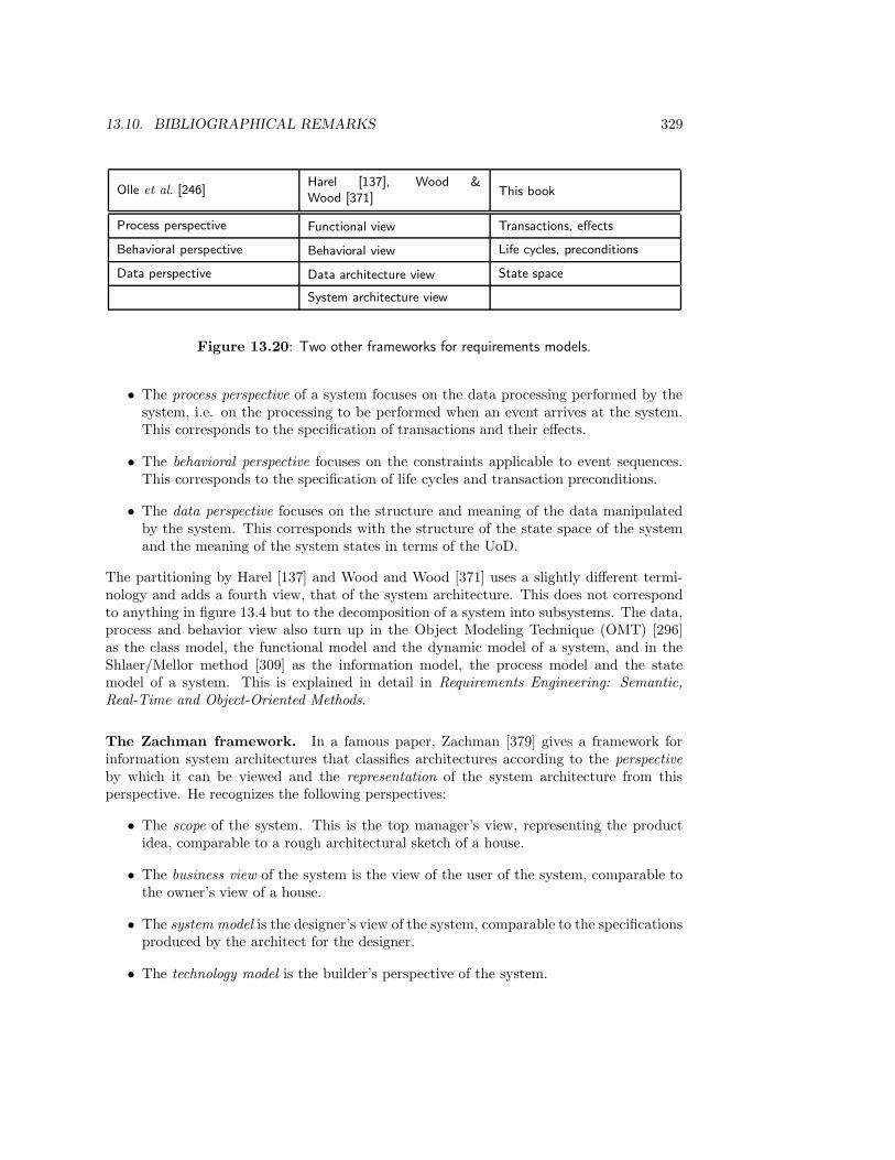
13.10. BIBLIOGRAPHICAL REMARKS 329
Olle et al. [246]Harel [137], Wood &Wood [371]
This book
Process perspective Functional view Transactions, effects
Behavioral perspective Behavioral view Life cycles, preconditions
Data perspective Data architecture view State space
System architecture view
Figure 13.20: Two other frameworks for requirements models.
• The process perspective of a system focuses on the data processing performed by thesystem, i.e. on the processing to be performed when an event arrives at the system.This corresponds to the specification of transactions and their effects.
• The behavioral perspective focuses on the constraints applicable to event sequences.This corresponds to the specification of life cycles and transaction preconditions.
• The data perspective focuses on the structure and meaning of the data manipulatedby the system. This corresponds with the structure of the state space of the systemand the meaning of the system states in terms of the UoD.
The partitioning by Harel [137] and Wood and Wood [371] uses a slightly different termi-nology and adds a fourth view, that of the system architecture. This does not correspondto anything in figure 13.4 but to the decomposition of a system into subsystems. The data,process and behavior view also turn up in the Object Modeling Technique (OMT) [296]as the class model, the functional model and the dynamic model of a system, and in theShlaer/Mellor method [309] as the information model, the process model and the statemodel of a system. This is explained in detail in Requirements Engineering: Semantic,Real-Time and Object-Oriented Methods.
The Zachman framework. In a famous paper, Zachman [379] gives a framework forinformation system architectures that classifies architectures according to the perspectiveby which it can be viewed and the representation of the system architecture from thisperspective. He recognizes the following perspectives:
• The scope of the system. This is the top manager’s view, representing the productidea, comparable to a rough architectural sketch of a house.
• The business view of the system is the view of the user of the system, comparable tothe owner’s view of a house.
• The system model is the designer’s view of the system, comparable to the specificationsproduced by the architect for the designer.
• The technology model is the builder’s perspective of the system.
330 A FRAMEWORK FOR REQUIREMENTS MODELS
• The component model is an explicit, context-free view of a component as would begiven to a subcontractor.
These perspectives interleave the movement from vague to explicit specification (productidea to explicit behavior description) with the movement from high to low level of aggre-gation (compound system to component). These are the horizontal and vertical dimensionof our framework for development methods, respectively (figure 3.9). Zachman recognizesthree kinds of representations that can be used for each perspective, the data description,the process description and the network description. For example, the designer’s data viewcould be represented by an ER diagram, his process view by a DF diagram, and his net-work view by a graph representing a network of processors. The data and process viewcorrespond with the data and functional views in figure 13.20. The network view repre-sents one particular decomposition of the system into subsystems that is interesting at therelevant level of abstraction. For example, the top level network view of a business couldrepresent the geographic locations of the business, the network of the enterprise perspectivecould consist of a logistics network, etc. This view is thus already part of our frameworkfor system development methods in figure 3.9. The data and process view are part of theframework for requirements specification models given in section 13.3.
In a later refinement of the framework, Sowa and Zachman [323] extend it with otherviews, viz. the people important to the business, the events significant to the business,and the important business goals. Relevant representation techniques for these views areorganization charts, schedules, and business plans. The people view represents a move tothe social system aspect, briefly discussed in section 3.6. The event view is part of thestate transition view of section 13.3 and the goals view corresponds to the objectives viewof figure 3.9.
Other frameworks. There are many other frameworks for classifying requirements mod-eling and system development methods. A popular dimension in many frameworks is theircoverage of different levels in the aggregation hierarchy. The assumption of these frame-works is that a top-down linear development strategy is used (see chapter 15), in whichrequirements for changes to a social system are determined first, after which these are de-composed to requirements on computer-based systems, and so on until the level of softwaresubsystems is reached. Development methods can be classified according to their coverageof this sequence of top-down stages. Fitzgerald, Stokes and Wood [104] and Hackathornand Karimi [130] use this as a classification principle. In other respects, these frameworksare not compatible with the one presented in this chapter. For example, the frameworkfor information system development methods defined by Fitzgerald, Stokes and Wood [104]classifies methods according to the following dimensions:
• Scope of the method: this corresponds to its coverage of stages in the linear top-downdevelopment strategy.
• Philosophy of the method: this is the leading idea that informs the method (i.e.solution of user problems in ISAC, data structuring in ER, data flow modeling inStructured Analysis, etc.). We could call this the product idea of the method.
• Assumptions of the method: these are the assumptions that the method makes aboutits environment of use. Examples of such assumptions are that information needs can
13.10. BIBLIOGRAPHICAL REMARKS 331
be modeled adequately, and that solutions to sub-problems lead to a solution of acompound problem.
• Skills: each method requires certain skills of its users, such as data processing skills,mathematical skills in case a formal specification language is used, etc.
• Tool support: for each method tool support may be provided.
Van Swede and Van Vliet [335] give a framework for information system methods andtechniques that distinguishes perspectives from aspects.
• The business perspective models the way the business is done,
• the information perspective represents the information needs of the business,
• the function perspective represents the external behavior of the system, and the im-plementation perspective represents the internal structure of the system.
The first two perspectives model the needs of the environment, the other two model externalbehavior and internal structure; jointly, they cover the three system views described inchapter 2. For each perspective, a number of views are distinguished: goals, functions,data, processes, communication, control, organization, technical structure and distribution.This list can be expanded and/or contracted as necessary. Note that these views are notorthogonal.
Integrated methods. Several proposals for integrated requirements modeling methodshave been made, that partly overlap with the proposal for an integrated ER-JSD-DF mod-eling method made here. The possibility to combine JSD modeling with ER modeling isbriefly discussed by Sutcliffe [332] but is not worked out in detail. Carswell and Navathe [61]propose to integrate DF and ER models by making an ER model of each data flow and thenjoining these ER diagram fragments by view integration. The resulting diagram includes anER diagram of data stores only, for the data flows entering and leaving data stores wouldby themselves yield that diagram. However, Carswell and Navathe’s proposal leads to anER model of nonpermanent data as well. The approach used in this chapter is the de factostandard in Structured Analysis and is presented by Yourdon [376].
Wrycza [372] combines the ISAC method with ER modeling by transforming the datamanipulated in activities into entity types, and the flows between activities into relation-ships. Hanani and Shoval [136, 311] combine ISAC with NIAM, a modeling method withroughly the same power as ER modeling, by following ISAC until the specification of in-formation systems, and using NIAM to define the structure of the data manipulated byinformation systems.
JSD and object-oriented requirements modeling. Booch [44] points out the useful-ness of JSD as a requirements modeling method for object-oriented design. Similar remarksare made by Masiero and Hermano [219], Hull et al. [151], Birchenough and Cameron [33]and Sutcliffe [333]. Wieringa [363] compares JSD with object-oriented analysis and Struc-tured Analysis. Sanden [301] shows how to integrate JSD with the Booch method.
An important difference between JSD and object-oriented modeling is the absence oftaxonomic structures in JSD. Adding these structures to JSD would create the problem of
332 A FRAMEWORK FOR REQUIREMENTS MODELS
how life cycles are inherited. This is still an open research problem. It is touched uponvery briefly by Rumbaugh et al. [296]. More thorough discussions are given by Lopes andCosta [197], McGregor and Dyer [224] and Saake et al. [298].
Integration of Structured and Object-Oriented Analysis Bailin [19] proposes anobject-oriented behavior specification method that defines objects in a way very close tothe representation of the student objects in figure 13.18. These high-level objects are de-composed in Bailin’s method into functional transformations as they are known from dataflow modeling. Objects do not necessarily correspond to entity types in the ER diagram.According to Bailin, there are passive entities that do not appear as objects but as dataflows in the high-level object-oriented diagram.
Ward [353] presents a similar way of representing objects by means of data flow dia-grams. The basic heuristic recommended by Ward is to partition the behavior specificationinto specifications of objects first and in specifications of concurrent parts later. This meansthat data transformations in high-level DF diagrams correspond to objects in an object-oriented requirements model of the system, and that concurrent tasks will appear lower inthe DF hierarchy. This contrasts with the heuristic given by Shumate [312] to partition thespecification into specifications of concurrent tasks first and, within tasks, into object spec-ifications. The difference is probably due to Shumate’s orientation on distributed systems,in which the objects are nodes in a distributed network, and Ward’s orientation on controlsystems, which are nondistributed systems that represent a UoD to be controlled. In Ward’sapproach, the UoD provides a useful partitioning criterion. This difference is related to thedifference between decomposing a requirements specification into modules, while staying atthe same level of aggregation, and decomposition the modeled system into subsystems. Inthe first decomposition, object identification is a good partitioning heuristic. In the second,concurrency gives a good partitioning heuristic.
Several authors propose preceding object-oriented system design with Structured Anal-ysis [6, 305]. Jalote [164] proposes an interleaving between functional decomposition andobject-oriented decomposition of a requirements specification, based upon a natural lan-guage analysis. Henderson-Sellers and Constantine [145] give a survey of the possibilities.A useful survey and comparison of object-oriented modeling and structured methods, bothfor analysis and design, is given by Fichman and Kemerer [101]. Their framework for com-parison of analysis methods is similar to the one given in figure 13.4, but contains moreconcepts. Two interesting concepts that they add are large scale model partitioning andthe ability to specify end-to-end processing sequences.
Reactive systems. The term “reactive system” was introduced by Manna and Pnueli [209].McMenamin and Palmer [225] use the term “planned response system” but mean the samething. Harel and Pnueli [140] contrast reactive systems with combinational systems (calledtransformational systems by them) that do not have a memory of past transactions. Theyargue that reactive systems are the hardest to specify, and that development of such systemswill proceed by jointly decomposing a specification into more detailed specifications at thesame level of aggregation, and decomposing the specified system into subsystems.
Quality Function Deployment. Useful references for quality function deployment areHauser and Clausing [142], Brown [54] and West [359].
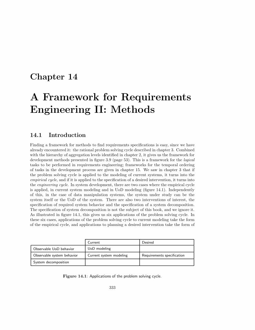
Chapter 14
A Framework for RequirementsEngineering II: Methods
14.1 Introduction
Finding a framework for methods to find requirements specifications is easy, since we havealready encountered it: the rational problem solving cycle described in chapter 3. Combinedwith the hierarchy of aggregation levels identified in chapter 2, it gives us the framework fordevelopment methods presented in figure 3.9 (page 53). This is a framework for the logicaltasks to be performed in requirements engineering; frameworks for the temporal orderingof tasks in the development process are given in chapter 15. We saw in chapter 3 that ifthe problem solving cycle is applied to the modeling of current systems, it turns into theempirical cycle, and if it is applied to the specification of a desired intervention, it turns intothe engineering cycle. In system development, there are two cases where the empirical cycleis applied, in current system modeling and in UoD modeling (figure 14.1). Independentlyof this, in the case of data manipulation systems, the system under study can be thesystem itself or the UoD of the system. There are also two interventions of interest, thespecification of required system behavior and the specification of a system decomposition.The specification of system decomposition is not the subject of this book, and we ignore it.As illustrated in figure 14.1, this gives us six applications of the problem solving cycle. Inthese six cases, applications of the problem solving cycle to current modeling take the formof the empirical cycle, and applications to planning a desired intervention take the form of
Current Desired
Observable UoD behavior UoD modeling
Observable system behavior Current system modeling Requirements specification
System decomposition
Figure 14.1: Applications of the problem solving cycle.
333

334 A FRAMEWORK FOR REQUIREMENTS METHODS
Current Desired
OrganizationISAC Change Analysis, Infor-mation Strategy Planning
Business information supplysystem
ISAC Activity Study
Observable UoD behaviorER modelingJSD modeling
Software systemEssential system modeling(SA)
DF specificationJSD function specification
Figure 14.2: Methods studied in this book.
Section Empirical cycle Engineering cycle
14.2 Starting points Observation Analysis
14.3 Finding a behavior speci-fication
Induction Synthesis
14.4 Evaluating a behaviorspecification
DeductionTest
SimulationEvaluation
Figure 14.3: Structure of this chapter.
the engineering cycle.To multiply the number of applications of the problem solving cycle even more, the
system in the figure may exist at any level in the aggregation hierarchy. For example,viewing an organization at least in part as a data manipulation system, we can be concernedwith modeling the UoD of the organization, i.e. the part of the world of interest to it, or wemay be concerned with performing an intervention to change this UoD into a desired state.We may also want to model the organization as it currently is, or plan an intervention tobring it into a desired state. Finally, we may study its decomposition into subsystems as itcurrently is, or we may plan an intervention to improve its decomposition into subsystems.Similar applications of the problem solving cycle can occur at the level of computer-basedsystems, software systems or at lower levels of the aggregation hierarchy.
Figure 14.2 shows the place of the methods reviewed in this book in the frameworkof figure 14.1. The business information supply system in figure 14.2 is a computer-basedsubsystem of the organization that may consist of many physically distributed informationsystems, some of which may be connected by networks. Only ISAC change analysis followsthe logical problem solving cycle very clearly. However, for all methods, we found that theproblem solving cycle provides a very useful framework to analyze the methods. In thischapter, we pull the results together under the headings shown in figure 14.3.
In section 14.2, we list possible starting points for problem solving: observations to bemade of current systems or desires to be realized by future systems. In section 14.3, we
14.2. STARTING POINTS 335
discuss the road map of methods to find models of the UoD or specifications of systemrequirements. In section 14.4, we summarize the methods for evaluating the quality of themodels or specifications found. Section 14.5 discusses alternative views of requirementsspecification, which seem to fall outside the framework for rational problem solving used inthis book.
14.2 Starting Points
The possible starting points for finding a model of a current system or a specification of de-sired system behavior are independent of the kind of methods used to find the models. Manyare even neutral with respect to modeling current or desired behavior; they can be used ineither modeling activity. Below, a list of possible starting points is given. Section 14.8 givessome pointers to literature where these methods are described in more detail.
• If we are working on a requirements specification for a computer-based system, ahigher-level requirements specification is a requirements specification for theorganization, i.e. a business strategy. If we are working at the software systemlevel, a higher-level requirements specification is a requirements specification for acomputer-based system, e.g. an information strategy plan produced by ISP.
• Participation in the activity in the current UoD or the current system provides alot of information useful for modeling and requirements specification. An example ofparticipation is taking over the job of a circulation desk employee for a few weeks.
• Less time consuming than participation is observation of activity in the currentUoD or the current system by walking around, talking with people, observing whathappens, etc.
• The analyst can perform experiments to discover aspects of current system behaviornot fully understood. These experiments may be very simple, such as pushing a buttonto see what happens, or they may require a complicated setup to obtain statisticallysignificant statements about current system properties.
• The client often finds it easy to describe scenarios that the SuD will have to partici-pate in. These are a rich source of material for the construction of behavior specifica-tions and, at a later stage, for the validation of specifications as well as for acceptancetesting of the product.
• Forms used in administrative systems give important clues as to what informationis currently required. These forms may be implemented on paper, as part of a user-interface, or as reports produced by a system. Forms to be manipulated in the desiredsituation give important information about the desired system.
• Record declarations used in a current system can be analyzed to discover whatinformation is currently stored. This may also give important clues about informationto be stored in a desired system.
• Quantitative documents provide interesting information about data relevant tocurrent or future systems. Examples of quantitative documents are status reports

336 A FRAMEWORK FOR REQUIREMENTS METHODS
about inventory, sales, production, turnover, etc. Many of these reports are producedmonthly, quarterly or yearly.
• Qualitative documents contain clues about information relevant for an organizationin the current or desired state of affairs. Examples of qualitative documents arememos, bulletin boards, procedure manuals, policy handbooks, etc.
• The company strategy may be laid down in a qualitative document that containsimportant information for the writer of requirements specifications.
• Product specifications of hardware or software systems are essential reading forthose who must model a current system, as well as for those who must specify asystem that must interface with other products.
• Interviews with sponsors, customers, users, domain specialists and other stakehold-ers in a development process provide crucial information about current problems andrequirements for the SuD.
• Questionnaires can be used to gather information from a larger population. Ques-tionnaires do not make unexpected facts visible.
• Reference models are important sources of reusable information for the writer ofrequirements specifications. Reference models are example models of standard ap-plications, that can be customized for a particular application. There are referencemodels of medical information systems, library information systems, production au-tomation systems, etc.
With so many sources of information, the analyst must unavoidably make a choice forcertain sources at the risk of missing important information available from another source.In other words, the analyst must sample data from a potentially very large collection. Thiscan be done using statistical techniques but, as Gause and Weinberg [111] remark, it is easyto get lost here in the details of a sound statistical design of the sample. To get significantresults, the most important thing is that the analyst is aware that he or she is sampling.
14.3 Finding a Behavior Specification
Figure 14.4 shows the road map of methods developed in part II, supplemented with thestarting points listed above. An explanation of the placement of these starting pointsfollows.
• A higher level requirements specification, strategy descriptions, or the written resultsof interviews or questionnaires provide a useful starting point for the definition ofa function decomposition tree of a computer-based system or a software product.Because they contain text, they can also be the starting point for natural languageanalysis.
• Quantitative and qualitative documents are additional starting points for naturallanguage analysis.

14.3. FINDING A BEHAVIOR SPECIFICATION 337
Functiondecomposition tree,
scenariosTransactions
Transaction/usetable
Transactiondecomposition
table
JSD modelof UoD
JSD modelof SuD
Referencemodel
Natural languagetext
Qualitative documents,Quantitative documents
Participation,Observation,Experimentation,Product specifications
Higher–levelrequirementsspecifications,Strategydescriptions,Interviews,Questionnares
Elementarysentences
ER model ofUoD or SuD
Recorddeclarations
Forms
Referencemodel
DF modelof SuD
Essential modelof current system
Current system
Forms
Recorddeclarations
Reference model
Event–responselist
JSD entities,JSD actions
Figure 14.4: Road map of methods to find models and specifications, with starting points.
338 A FRAMEWORK FOR REQUIREMENTS METHODS
• Participation, observation and required scenarios give information about what trans-actions current systems perform, or what transactions would be desirable for a futuresystem.
• Record declarations and forms are useful as a starting point for finding an ER model.Because the arrival of a filled-in form, or the update of a record, are events to whicha system must react, they can also be used as starting points for DF modeling. As amatter of fact, a DF diagram can be viewed as a model of the flow of forms throughan organization.
• Domain models can be useful starting points for ER modeling, DF modeling and JSDmodeling, because they contain what can be generally expected to be relevant for aparticular kind of application.
14.4 Evaluating a Behavior Specification
Figure 14.5 summarizes the evaluation methods of the reviewed modeling methods, classifiedaccording to the criteria for requirements specifications given in figure 4.4 (page 77). Amotivation of this classification follows.
• Communicability is enhanced if we minimize the number of relationships in anER model, and minimize the arity of each relationship. In a data flow model, it isenhanced if we minimize the interfaces between model components.
• Truth of an ER model of the UoD can be verified, partly, by checking whetherthe modeling constructs are used correctly. Thus, we check whether we properlydistinguished entities, links and values and whether the is a relationship in the modelis a true representation of reality. Similar checks on the use of modeling constructscan be performed for JSD models.
There are a number of validity checks that are independent of the modeling techniquesand notations used. The elementary sentence check and population check were definedoriginally for the NIAM method [244] and were adapted in chapter 8 to the ER method.
• Completeness is enhanced if we check whether every entity is accessed by a transac-tion (horizontal balancing, data usage), in particular whether it is created or deletedin the model (creation/deletion check). We should also check whether the output ofevery data transformation has been specified completely in terms of its input (deter-minism). Building a model of one aspect of the system in different ways leads to morecomplete models (cross-checking), as does integration of models of different aspects(view integration).
• One aspect of feasibility is consistency. Consistency of the specification is enhancedif we follow several paths in our road map, possibly in reverse direction, and cross-check the results. In particular, we can check whether all queries can be answered(navigation check). In a data flow model, we should take care that the different partsof the model are mutually consistent (horizontal balancing) and that the differentlevels in a hierarchical DFD are consistent (vertical balancing). Cost-effectiveness ofa specification can be verified by means of walkthroughs.

14.4. EVALUATING A BEHAVIOR SPECIFICATION 339
ER DFD JSD
Communica-bility
• Derivable relation-ship check
• Minimal aritycheck
• Minimality checks
Truth
• Entity/valuechecks
• Entity/link checks
• Specializationcheck
• JSD entity checks
• JSD action checks
• Action allocationchecks
• Common actionchecks
• Life cycle check
• Explanation: Explain the model in natural language. This generalizesthe elementary sentence check of ER modeling.
• Population check: Show some possible states of the system to thedomain specialist.
Completeness
• Creation/deletioncheck
• View integration
• Cross-checking
• Determinismcheck
• Horizontal balanc-ing
• Data usage
Feasibility• Cross-checking
• Navigation check
• Horizontal balanc-ing
• Vertical balancing
• Walkthrough
General qual-ity checks
• Walkthrough: Walk the domain specialist through the model.
• Inspection: Verify that the model satisfies particular quality criteria.
• Requirements prototyping: Specify requirements in an executablelanguage, execute the specification, observe the result and evaluate it.In model animation, the result is shown graphically, using dynamicinterfaces. A low-tech mockup of a system that would satisfy therequirements also falls under this category.
Figure 14.5: Evaluation methods for requirements specifications.
340 A FRAMEWORK FOR REQUIREMENTS METHODS
• General quality checks can take the form of walkthroughs or inspections. Ex-ecutable specifications can take a variety of forms, from high-tech execution ofa formal specification, whose results are presented in a pleasing graphical form, tolow-tech paper-based mockups of the system.
Looking at the requirements on requirements specifications listed in figure 4.4 (page 77), weremark that there are no checks on the verifiability and maintainability of a requirementsspecification. This can be explained by the fact that these are really properties of notationsystems and tool support for requirements specifications, rather than for requirements spec-ifications themselves. Traceability and modifiability, both aspects of maintainability, mustfor example be provided by tools for requirements specification languages, that should allowthe writer of a specification to estimate the impact of a modification, to link parts of therequirements to system components, etc.
14.5 Requirements Engineering as Negotiation aboutMeanings
In this book the rational problem solving method is used as a framework for understandingrequirements specification and current system modeling. It has been emphasized severaltimes that the rational problem solving cycle is not a model for planning the requirementsspecification process. The relationship between the actual process and the rational problemsolving method is the subject of the final two chapters of this book. However, even takingthis caveat into account, there is a process in requirements engineering that seems to eludethe framework of rational problem solving. This is the process of negotiation.
14.5.1 Negotiation in discovery and engineering
First, it must be remarked that negotiation occurs in the process of scientific discovery. In asimplistic view of the empirical cycle of discovery, we observe phenomena in the world, for-mulate hypotheses to explain them, and reject any hypothesis falsified by experiments. Thereality of empirical research is not that simple. For example, we cannot observe phenomenawithout theories. If measuring instruments are used, then these instruments are built usingtheories that are assumed to be true and that are not under discussion when studying thefacts observed with the help of those instruments. For example, observation of the behaviorof distant galaxies requires sophisticated optical and electronic equipment, that exemplifiestheories of optics and electronics not under discussion (at least not by astronomers). Inaddition, the observed phenomena can only be described by means of a number of generalterms defined by scientific theories. Even a term like “galaxy” only has meaning if we as-sume a certain theory about the cosmos — it is meaningless if we assume that the stars arefallen angels. This means that if we make a prediction on the basis of a hypothesis, thenthere are numerous auxiliary hypotheses, drawn from other scientific theories, that are usedin this inference; and if the prediction is falsified, any of these auxiliary hypotheses can beconsidered falsified. All of this shows that in the application of empirical cycle we need tomake decisions about what to accept and what to doubt. Having made these decisions, wecan proceed as if we follow the rational empirical cycle; but if we don’t like the results, wereturn to the decisions and adjust them. This is not a solitary process but a social process,
14.5. REQUIREMENTS ENGINEERING AS NEGOTIATION ABOUT MEANINGS341
in which scientists weigh evidence, choose to maintain beliefs accepted as certain, and doubtother ideas. In many areas of science, scientists are divided into schools of thought thattend to make these decisions differently. The important thing to note is that this processis as much a negotiation about the meaning of theoretical terms as it is a rational processof problem solving.
Turning to engineering, we see negotiations going on as well. From a rational point ofview, the engineer observes desires existing in the market or the client, translates these inobjectives, writes a behavior specification, decomposes the product, and tells the buildershow to implement it. However, as already remarked in chapter 3, the very act of findingout what the desires of clients are, may change those desires. This is the principle ofrequirements uncertainty. In addition, when a specification or implemented product doesnot satisfy the stated objectives, we may change the objectives or the product. This isa decision made by the sponsor, users, customers and the market and its outcome is notquite predictable. To compound the situation, the engineers, sponsors, users, customers andthe marketing department may all have different objectives, and may be divided amongstthemselves in competing factions. In such a situation, the result of evaluating a productspecification or an implemented product may be just as much the result of negotiation as itis of rational problem solving. And much of this negotiation is about what the meaning ofdocuments is: the meaning of a behavior specification, of a decomposition specification, ofa statement of objectives, of a market analysis, of an interface specification, etc. is never asunambiguously determined as the meaning of a mathematical formula is — assuming thatformulas are unambiguous.
The conclusion of these observations must not be that the rational problem solving cycleis useless, but simply that it does not describe the structure of the discovery and engineeringprocesses. The rational problem solving cycle accurately describes the structure of a rationalreconstruction of the process by which results are obtained in the discovery or engineeringprocess. Even though the discovery and engineering processes do not follow the patternof rational problem solving, the validity of the results obtained by these processes can andmust be justified by reconstructing the process as if the rational cycle were followed. Therole of rational reconstruction in system development is elaborated upon in chapter 15.Here, we note that the phenomenon of negotiation during discovery and engineering doesnot invalidate the usefulness of the rational problem solving cycle as a tool for the analysisof development methods, or as a tool for the justification of the results of development.
14.5.2 Implicit conceptual models and the ultimate communicationbreakdown
Software systems and computer-based systems are data-manipulation systems embedded insocial systems. They often function as linguistic machines, answering queries, issuing com-mands and asking questions, and this makes the phenomenon of negotiation about meaningduring their development even more important. The reason for this is that social systemsare full of implicit meanings, while at the same time computer-based systems are devoidof any implicit meanings. Requirements engineering of a computer-based system must, atsome point, make all relevant meanings of the data manipulated by the system totally ex-plicit. To understand why this is a problem, consider first the extent to which meanings areimplicit in social systems. The day-to-day affairs of people consist of describing to them-selves and others what the world is in which they live, as well as prescribing to themselves

342 A FRAMEWORK FOR REQUIREMENTS METHODS
and others what the world ought to be. During meetings, coffee breaks, lunch, gossip andbusiness appointments, people talk about what happened, what ought to have happened,what will happen and what ought to happen. This everyday process took place beforecomputer-based system development started, takes place during system development, andwill continue to take place after development finishes. Let us call this implicit conceptualmodeling, because it consists of producing and maintaining, by conversation with others,an implicit conceptual model of the universe of everyday discourse. Like all conceptualmodels, an implicit conceptual model is a set of shared concepts used by people in commu-nicating about a UoD. What makes this conceptual modeling implicit is that it is not itselfthe subject of discussion but functions in the background of conversation, unnoticed by thespeakers.
To get an impression of the contents of such an implicit conceptual model, consider whatwe know about the library and what is not specified in the explicit conceptual models ofthe library used in this book. An ER model just says that there is an entity type calledDOCUMENT , that can be borrowed by entities of type MEMBER. Our implicit modelof this contains, among others, the knowledge that documents can be read, that readingcan be fun or can be boring, that some documents are rare, and that they may be valuable;it contains fond memories of some of our children’s books as well as our opinion that thereshould be freedom of the press. If we think about this for a while, we realize that there isa sheer inexhaustible stock of everyday knowledge about books and documents that everynormal member of our society knows but that no one cares to spell out in detail.
As another example of implicit conceptual models, take the following traffic violationdata:
Day: May 28 Time: 5:00 p.m. Day of week: TuesdaySex: Male Height: 5’ 2”Hair: Brown Weight: 120Eyes: Blue Birthdate: 12-7-11
Violation(s): 21651 V.C. Divided highway driving to left of divided section;Driving W/B on wrong side of Shoreline Dr. against E/B traffic. Approximatespeed: 20 mph.
To interpret this data, we need an implicit conceptual model that tells us what is norm,usual, expected, relevant, etc. This is illustrated by the interpretation of this data by anexperienced traffic violation judge (Pollner [262, page 33]):
“See, here it says nineteen-eleven (1911) — he’s an oldster. Now the fact thatit says which traffic he was driving against and the time when he did it tells meits murderous — its thick traffic. No business address so the guy is probablyretired. So he wasn’t doing as if he were taking a chance. He just didn’t know.He wasn’t doing it intentionally. He was driving right into the sun. He probablydidn’t see or something. Now if it was an eighteen year old kid it’s somethingelse. There you have to search for what he was up to. The ticket tells you whathe’s like, what’s he driving; does he work, anything about his occupation, wheredoes he live, how old is he, can he pay, is he rich or poor. What was he driving?A fast car?”
Every member of a culture has an implicit conceptual model of things that can happen ineveryday life. We can communicate with each other because much of our implicit conceptual
14.5. REQUIREMENTS ENGINEERING AS NEGOTIATION ABOUT MEANINGS343
models is shared and we need not talk about it. Similarly, we can interpret what people doin daily life because we have internalized a shared and implicit conceptual model that tellsus what other people normally do in certain circumstances, and what we should normallydo under certain circumstances. When we invite someone for lunch, we do not have toexplain to him or her what lunch is, nor do we have to explain how you normally behaveduring lunch.
The shared part of implicit conceptual models functions as the background of normalconversation and action. Only if communication breaks down or if we are puzzled bysomeone’s behavior, does it become necessary to reflect upon the contents of both ourimplicit conceptual models. This happens for example if we are transferred to a differentculture. Eating habits, dress codes and etiquette may be different. Minor breakdowns alsooccur if we move to another job and we have to learn “how things are done around here”.
When breakdown occurs, participants in the conversation can restore things to normalby a negotiation process in which they try to figure out what the other’s implicit model ofthe state of affairs is, and by trying to influence the other’s model and adjust their ownmodel such that an agreement is reached about what is the case and about what oughtto be done. This negotiation process is descriptive as well as prescriptive. As pointed outbefore, much of this negotiation is a negotiation about the meaning of words, e.g. aboutthe meaning of “document”, “book”, “loan”, etc. This negotiation is not only a process oflinguistic analysis but also a negotiation about norms. For example, when we define “loan”,we also state how a library member ought to behave.
Turning now to computer-based systems, the ultimate breakdown in communicationoccurs if we try to communicate a model of the universe of our discourse to a computer,for the computer by itself (without being programmed) understands nothing and has noconceptual model of anything. Yet, when the system is used, it functions as a linguisticmachine that performs speech acts. It answers questions, poses questions, gives commands,obeys commands, etc. It thus functions as a linguistic actor without any knowledge ofimplicit meanings and it functions in a social environment that is full of implicit meanings.We are therefore forced to make whatever is relevant totally explicit in our specification ofrequired product behavior, and we must make the explicit meaning understood and sharedby all users. Success of these negotiations about meaning is a crucial factor in the successof the delivered result.
The upshot of the gap between our social world on the one hand, filled with an in-exhaustible mass of implicit meanings, and computer-based systems on the other, devoidof any implicit meanings, is that negotiations about norms, problems, objectives, feasiblesolutions, shared interests and mutual conflicts can take very long, because the result mustbe totally explicit and unambiguous. If we were to try to make everything in an implicitconceptual model explicit, then we would discover that there is no end to this process.As Codd said, the task of capturing the meaning of data is a never-ending one [70]. Onthe other hand, if we leave too much implicit, then misunderstandings will arise when thesystem is used and this too degrades the quality of the system.
All of this does not invalidate the use of the rational problem solving method as frame-work for requirements specification. In the sometimes confusing network of implicit mean-ings and possibilities, it can be very useful to structure the negotiation by considering somefacts as problems and others as non-problems, some options as feasible alternatives andothers as out of bounds, and performing simulations which show us what the consequencesof some of these alternatives are. However, the analyst must be prepared for the existence of
344 A FRAMEWORK FOR REQUIREMENTS METHODS
a vast amount of unstated assumptions and norms and meanings, which, though invisible,have a pervasive influence on the requirements engineering process.
14.6 Summary
The rational problem solving method can be used as a framework to analyze methods forcurrent systems modeling, UoD modeling and for behavior specification. The tasks recom-mended in a particular modeling or engineering method can be classified as belonging toone of the tasks in the rational problem solving method. The starting point of modeling isobservation, and the starting point of engineering is analysis. There are numerous methodsfor observation and analysis, including analyzing a higher-level requirements specification,participation, observation, performing experiments, form analysis, record analysis, ana-lyzing quantitative or qualitative documents, analyzing strategy statements, interviewingstakeholders, using questionnaires, analyzing interface specifications and analyzing domainmodels.
From these starting points, one can follow various roads through our road map (fig-ure 14.4) of methods to find models or specifications. This corresponds to induction in theempirical cycle of modeling, and to synthesis in the requirements engineering cycle.
Having found a behavior model, one can evaluate it by deducing observable consequencesand testing these; having found a behavior specification, it can be evaluated by simulatingthem and evaluating the results. There are a number of methods (figure 14.5) for evalu-ating the quality of a model or a specification. These evaluate different aspects, such ascommunicability, completeness, feasibility, and truth of the model or specification. We havefound no checks for verifiability or maintainability, probably because these are characteris-tics for language and tool support rather than of a particular behavior model or behaviorspecification.
In practice, modeling and engineering often have the character of negotiation aboutmeaning. This does not invalidate the usefulness of the rational problem solving cycle asa tool for analyzing methods and as a target for the rational reconstruction of the way inwhich the results were obtained, but it does point out that the process of obtaining theseresults may be very dynamic. In the case of requirements engineering of computer-basedsystems, the negotiations must lead to results that must be more explicit and unambiguousthan is usual, because computer-based systems are devoid of any implicit meanings, butthey will function in a world that assumes many implicit meanings.
14.7 Exercises
1. In the library case study, we followed all paths in the road map of figure 14.4. Thetransaction decomposition table is a central deliverable that can be produced on theway to a DF model as well as on the way to a JSD model of the system. Check whetherthe action allocation table of figure 12.4 corresponds to the transaction decompositiontable given in figure 10.9. Explain any differences you find.
2. In the example of section 14.5, the judge used elements of her implicit conceptualmodel of traffic violations in interpreting the traffic violation data. Make a list of theelements she used.

14.8. BIBLIOGRAPHICAL REMARKS 345
14.8 Bibliographical Remarks
Starting points. A good introduction to sampling, interviewing and conducting ques-tionnaires, with pointers to further literature, is given by Kendall and Kendall [174]. Byrd,Cossick and Zmud [55] give a useful survey of observation methods used for informationsystems and expert systems. Gutierrez [129] gives a survey of observation methods thatcan be used for information system development. Goguen and Linde [117] provide a crit-ical analysis of several observation methods, including interviewing, protocol analysis anddiscourse analysis.
Finding a description. The bibliographical remarks in the chapters of part II give point-ers to the literature on methods for finding models and specifications of systems. Notmentioned in those chapters are methods for form and record analysis. A practical andcomprehensive introduction to form and record analysis for finding ER and DF models isgiven by Rock-Evans [281, 283]. A compressed version of this is presented in a shorterwork [284]. Another useful introduction to form and record analysis is given by Batini, Ceriand Navathe [25].
Evaluating a description. Again, pointers to the literature on evaluation methods havebeen given in the chapters of part II. Not mentioned there are inspections, which were intro-duced in software development by Fagan [99, 100]. Walkthroughs are popular in StructuredAnalysis [375]. A survey of inspection and walkthrough techniques is given by Freedman andWeinberg [107]. A good introduction to verification and validation is given by Boehm [38].Lindland, Sindre and Sølvberg [194] emphasize that requirements must be evaluated ontheir feasibility.
Requirements engineering as negotiation. Hirschheim and Klein [146] provide anintroduction to alternative approaches to requirements engineering. According to what theycall the objectivist position, the social world exists independently from its observers andcan be described by causal models. According to the subjectivist position, the social worldis a subjective construction, and only participation in a social system can create the socialpreconditions for understanding and interpreting it. Independently from the subjectivist-objectivist axis, Hirschheim and Klein sketch an opposition between those who view thesocial world as characterized by order and functional coordination and those who see itas characterized by change and conflict. Clearly, the requirements engineering methodsdiscussed in this book take the objectivist-order position (with the possible exceptions ofISAC and ETHICS, which are closer to a subjectivist-order position). In my opinion,the UoD of data- or communication-intensive systems is a social construction that can bestudied objectively. The analyst must distinguish his or her role as a participant and asexternal observer of the UoD. But because the analyst plays both roles, he or she mustbe able to switch between a subjectivist and an objectivist view of the social world. Forexample, as a subjectivist, the analyst understands that the social nature of a UoD andof the context of use of computer-based systems is an important source for requirementsuncertainty (see subsection 3.3.3) and product evolution (figure 3.14). By being able to playboth roles, the analyst becomes aware of the conflict between distance and engagementnoted in subsection 3.5.3. The validity of the subjectivist view does not mean that we

346 A FRAMEWORK FOR REQUIREMENTS METHODS
should abandon the search for objectively true statements. It just means that this searchnever ends.
Mangham [208] provides illustrations of how to use negotiation skills to direct a processof organizational change. Berger and Luckmann [29] is the classic source for how theinteraction of people in a society results in the construction of a social reality. Negotiationplays a central role in this process. A classic source on the role of implicit knowledge inscience and day-to-day affairs is Polanyi [260, 261]. Another interesting source for the roleof implicit conceptual models is Garfinkel [109], who is the main driving source behind amethod for investigating implicit models called ethnomethodology. A handy because briefintroduction to these ideas is given by Agre [3]. Giddens [113] uses these and other ideas toargue for the duality of implicit models, which act at the same time as background to whatwe do and say, but which at the same time may be in the foreground, because our actionsand statements are oriented at influencing each other’s models. Winograd [368] gives a veryinsightful introduction to the role of implicit models and background knowledge in dailyconversation, and to the role of breakdowns in conversation in explicating the contents ofour background knowledge. Winograd and Flores [369] draw consequences from this for thedesign of computer-based systems. Giddens as well as Winograd draw upon Heidegger [143]for their ideas about the role of the background in normal speaking and doing, and for thedisruptive effects of breakdowns on this role.

Chapter 15
Development Strategies
15.1 Introduction
We now turn to the temporal ordering of tasks during the development process. Most ofthe methods discussed in part II concentrate on the logical tasks to be performed whendeveloping a computer-based system. The framework of chapter 3 contains the dimensionsof logic and aggregation level and therefore suffices to analyze these methods. We now adda third dimension, that of time, and ask how the problem solving tasks are to be orderedin time. This is the province of development planning, which itself is a part of processmanagement.
In section 15.2, we give an overview of the different kinds of process management tasks.These are universal, because they appear in any process in which objectives must be achievedby the effort of others. Accordingly, many of the methods and techniques for processmanagement are applicable in the management of a product development process. However,some tasks in the software product development process require special methods, or at leastmethods that are adapted to software product development. In these final two chaptersof the book, we focus on one of these tasks, strategy planning. In the current chapter, wediscuss a number of important software development strategies and in the the next chapter,we turn to methods to select the appropriate strategy for a development process.
In section 15.3 we discuss the linear development strategy, the splashing waterfall strat-egy, and the V-strategy. In section 15.4, these strategies are combined into a model of theconcurrent development. In section 15.5, we describe throw-away prototyping as a way toreduce uncertainty before a product is constructed, and in section 15.6 we describe phaseddelivery as a strategy to reduce uncertainty based on early experience with a finished ver-sion of the product. In section 15.7, we return to our three-dimensional framework fordevelopment methods and argue that the relationship between the temporal and logical di-mension of the framework is that the logical dimension provides a template for the rationalreconstruction of what happened along the temporal dimension.
Figure 15.1 shows our classification of development tasks into product engineering andprocess management tasks. The product engineering task is further subclassified asfollows:
• Requirements engineering, which produces a behavior specification of a product (at a
347

348 CHAPTER 15. DEVELOPMENT STRATEGIES
certain aggregation level).
• System decomposition, which produces a specification of a decomposition of a systemat a certain aggregation level into subsystems (at the next lower aggregation level).
• System integration, which produces a system as an assembly of subsystems.
• System testing, which applies tests to the system, observes the results, evaluates theseand adjusts the system or its specifications if necessary.
Decomposition, integration and testing are part of the regulatory cycle as it is followed inproduct implementation. This is discussed in detail in section 15.3. The process man-agement tasks are discussed in the next section. Figure 15.1 serves as a guideline for therest of this chapter and also relates it to the methods discussed in part II.
15.2 Process Management
We follow Mackenzie [206] in his definition of management as the achievement of objectivesthrough others. In order to achieve objectives by the effort of others, we must determine theobjectives (plan), acquire resources, break down the work into manageable units (organize),motivate the workers (direct) and compare the results against the objectives (control).There is no temporal sequence in these activities: in general, management performs all ofthese tasks in parallel. Thayer [342, table 2.2] gives a more detailed breakdown of the tasksof management, reproduced in figure 15.2. A simplified version of this has already beengiven in figure 6.10. In Thayer’s list, the acquisition of resources is viewed as staffing thedevelopment process. This ignores acquisition of other resources like hardware and softwaretools which aid in the performance of the development process and in the work breakdownof figure 15.1, we replaced staffing with acquisition. Note that even after this change, thelist makes abundantly clear that management is a people-oriented activity. All managementactivities are concerned with what people must do, why they must do it, who should do it,what they should do it with, whether they like to do it, and whether they have done it.
Management tasks are universal in the sense that they occur in the management of anyprocess in which results are achieved by the effort of others. This means that the logicalproblem solving methods for behavior specification and product decomposition are inde-pendent from methods for process management. This implies in turn that it is possible toeliminate any reference to process management from requirements engineering and productdecomposition methods and vice versa. But if these references can be eliminated, theyshould be eliminated. One advantage of such an elimination is that this simplifies the pre-sentation of the requirements engineering and product decomposition methods as well as ofprocess management methods. A second advantage is that it makes the use of these methodsmore flexible, because requirements engineering and product decomposition methods can becombined as needed with process management methods. For example, a particular behaviorspecification method can be combined with different company standards for process man-agement methods. Conversely, a development strategy like incremental development can becombined with structured as well as with object-oriented behavior specification methods.
A number of management tasks receive special attention in the management of softwareproduct development. Without being exhaustive, we list a number of them:
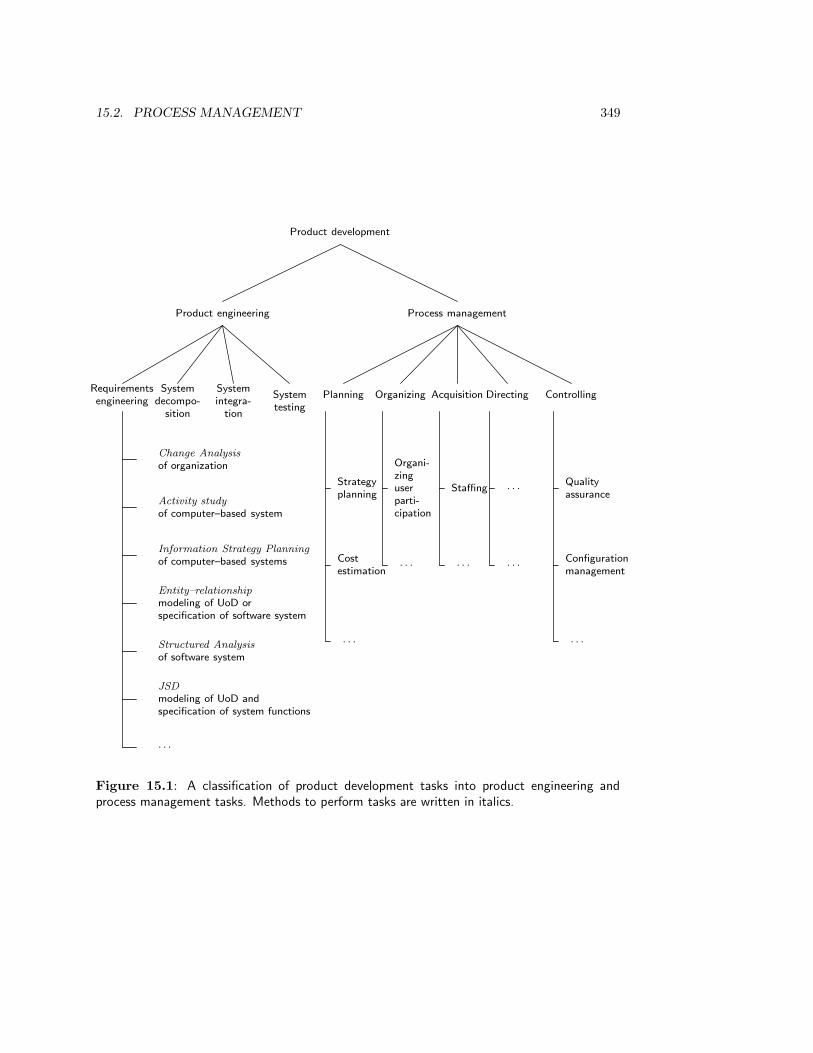
15.2. PROCESS MANAGEMENT 349
Product development
Product engineering Process management
Requirements
engineering
System
decompo-
sition
System
integra-
tion
System
testing
Planning Organizing Acquisition Directing Controlling
Change Analysis
of organization
Activity study
of computer–based system
Information Strategy Planning
of computer–based systems
Entity–relationship
modeling of UoD or
specification of software system
Structured Analysis
of software system
JSD
modeling of UoD and
specification of system functions
· · ·
Strategy
planning
Cost
estimation
· · ·
Organi-
zing
user
parti-
cipation
· · ·
Staffing
· · ·
· · ·
· · ·
Quality
assurance
Configuration
management
· · ·
Figure 15.1: A classification of product development tasks into product engineering andprocess management tasks. Methods to perform tasks are written in italics.

350 CHAPTER 15. DEVELOPMENT STRATEGIES
• Planning: Predetermining a course of action for accomplishing organizational objectives.
— Set objectives or goals.
— Develop strategies.
— Develop policies.
— Determine courses of action.
— Make decisions.
— Set procedures and rules.
— Develop programs.
— Forecast future situations.
— Prepare budgets.
— Document project plans.
• Organizing: Arranging work, granting responsibility and authority.
— Identify and group required tasks.
— Select and establish organizational structures.
— Create organizational positions.
— Define responsibilities and authority.
— Establish position qualifications.
— Document organizational structures.
• Staffing: Selecting and training people for positions in the organization.
— Fill organizational positions.
— Assimilate newly assigned personnel.
— Educate or train personnel.
— Provide for general development.
— Evaluate and appraise personnel.
— Compensate.
— Terminate assignments.
— Document staffing decisions.
• Directing: Creating an atmosphere that will assist and motivate people to achieve desired
end results.
— Provide leadership.
— Supervise personnel.
— Delegate authority.
— Motivate personnel.
— Coordinate activities.
— Facilitate communications.
— Resolve conflicts.
— Manage changes.
— Document directing decisions.
• Controlling: Measuring and correcting performance of activities toward objectives according
to plan.
— Develop standards of performance.
— Establish monitoring and reporting systems.
— Measure results.
— Initiate corrective actions.
— Reward and discipline.
— Document controlling methods.
Figure 15.2: Universal management activities [342]. Reproduced by permission of IEEEComputer Society Press, 1988.

15.3. TOP-DOWN DEVELOPMENT STRATEGIES 351
• Development strategy planning. These determine the sequence of activities toperform during development. Selecting a development strategy is a part of the deve-lopment planning task.
• Cost estimation. Estimating the cost of software is a difficult task, for which nu-merous methods have been proposed. Cost estimation is a part of the planning task.
• Participation. Users, customers, domain specialists and other interested parties maywant to be involved in different degrees in the development process. There are severalmethods to do this and thereby increase the quality of the product or speed up thedevelopment process. Setting up a participatory structure is part of the organizingtask.
• Quality assurance. During any product development process, procedures must befollowed for assuring the quality of the delivered product. Quality assurance is partof the controlling task.
• Configuration management. During any development process, different versionsof a product and its components may exist simultaneously. In addition, developmentresources are acquired, used and disposed. Configuration management methods dealwith the proper management of all these items. Configuration management is part ofthe organizing task.
In the rest of this book, we focus on development strategy planning.
15.3 Top-down Development Strategies
The development strategies discussed in this section have been proposed primarily for client-oriented software product development. As explained in chapter 3, this means that productdecomposition is also product implementation (because the product is software) and thatthere is no production process (because in client-oriented development there is only oneinstance of the product). Even for market-oriented software product development, we neednot specify a complex production process in which many instances of a product type areproduced in series. The real problem of market-oriented software production is the realiza-tion and maintenance of platform-independence. The strategies discussed here can easily begeneralized to product development in general, software and non-software, client-orientedand market-oriented.
All strategies assume that there has been a development process in a social system, inwhich a solution to a need of the social system has been specified. Let us assume for thesake of the example that the social system is a business. The development process may havebeen a problem solving process (such as in ISAC change analysis) or a strategy developmentprocess (such as in Information Strategy Planning). This process produces a charter fora new development process and we assume that this charter assigns developers to the taskof implementing a computer-based system as part of an implementation of the solution.For example, the charter may ask them to produce a customized information system in aclient-oriented development process, or to select a software package that satisfies businessneeds.
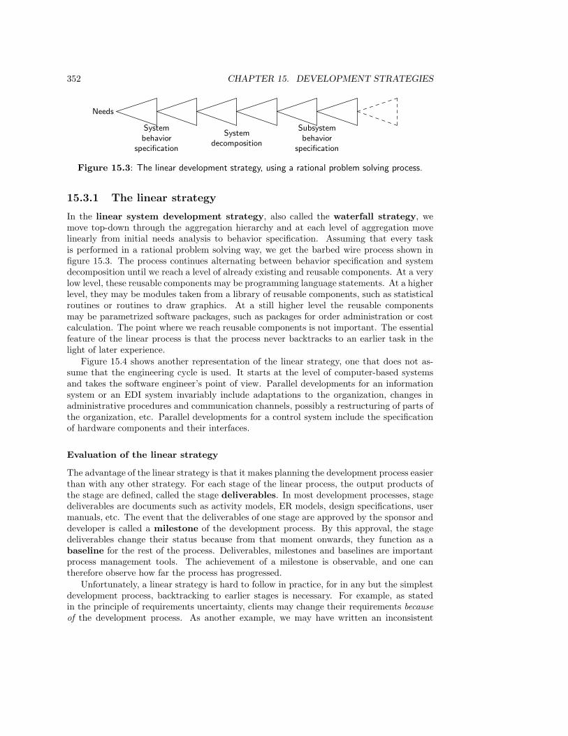
352 CHAPTER 15. DEVELOPMENT STRATEGIES
Needs
Systembehavior
specification
Systemdecomposition
Subsystembehavior
specification
Figure 15.3: The linear development strategy, using a rational problem solving process.
15.3.1 The linear strategy
In the linear system development strategy, also called the waterfall strategy, wemove top-down through the aggregation hierarchy and at each level of aggregation movelinearly from initial needs analysis to behavior specification. Assuming that every taskis performed in a rational problem solving way, we get the barbed wire process shown infigure 15.3. The process continues alternating between behavior specification and systemdecomposition until we reach a level of already existing and reusable components. At a verylow level, these reusable components may be programming language statements. At a higherlevel, they may be modules taken from a library of reusable components, such as statisticalroutines or routines to draw graphics. At a still higher level the reusable componentsmay be parametrized software packages, such as packages for order administration or costcalculation. The point where we reach reusable components is not important. The essentialfeature of the linear process is that the process never backtracks to an earlier task in thelight of later experience.
Figure 15.4 shows another representation of the linear strategy, one that does not as-sume that the engineering cycle is used. It starts at the level of computer-based systemsand takes the software engineer’s point of view. Parallel developments for an informationsystem or an EDI system invariably include adaptations to the organization, changes inadministrative procedures and communication channels, possibly a restructuring of parts ofthe organization, etc. Parallel developments for a control system include the specificationof hardware components and their interfaces.
Evaluation of the linear strategy
The advantage of the linear strategy is that it makes planning the development process easierthan with any other strategy. For each stage of the linear process, the output products ofthe stage are defined, called the stage deliverables. In most development processes, stagedeliverables are documents such as activity models, ER models, design specifications, usermanuals, etc. The event that the deliverables of one stage are approved by the sponsor anddeveloper is called a milestone of the development process. By this approval, the stagedeliverables change their status because from that moment onwards, they function as abaseline for the rest of the process. Deliverables, milestones and baselines are importantprocess management tools. The achievement of a milestone is observable, and one cantherefore observe how far the process has progressed.
Unfortunately, a linear strategy is hard to follow in practice, for in any but the simplestdevelopment process, backtracking to earlier stages is necessary. For example, as statedin the principle of requirements uncertainty, clients may change their requirements becauseof the development process. As another example, we may have written an inconsistent
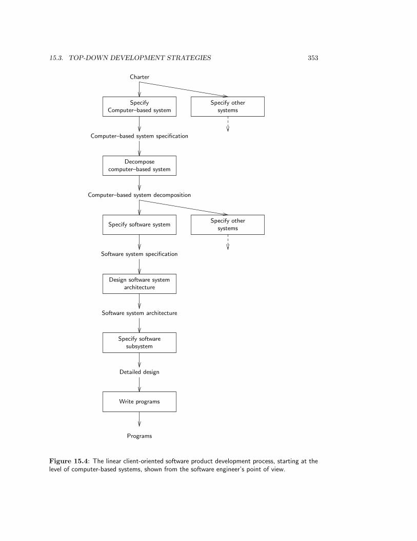
15.3. TOP-DOWN DEVELOPMENT STRATEGIES 353
Charter
SpecifyComputer–based system
Specify othersystems
Computer–based system specification
Decomposecomputer–based system
Computer–based system decomposition
Specify software systemSpecify other
systems
Software system specification
Design software systemarchitecture
Software system architecture
Specify softwaresubsystem
Detailed design
Write programs
Programs
Figure 15.4: The linear client-oriented software product development process, starting at thelevel of computer-based systems, shown from the software engineer’s point of view.

354 CHAPTER 15. DEVELOPMENT STRATEGIES
or incomplete system specification, or a specification that can only be implemented at avery high cost. These and many other reasons may cause us to backtrack to tasks alreadyperformed.
There are two kinds of feedback loops that can be added to the linear strategy, feedbackto the previous stage and feedback from the evaluation of an implementation. We discussthese as two distinct extensions if the linear strategy. In practice, of course, both kinds offeedback can occur in one development process.
15.3.2 The splashing waterfall strategy
The splashing waterfall strategy is an extension of the linear strategy with feedbackloops to the preceding stage of development, as shown in figure 15.5. It is left open howfar backtracking goes, one or more stages back. The name “splashing waterfall strategy”is explained by the fact that this strategy allows “water” to flow against the flow of thedevelopment process.
Evaluation of the waterfall strategy
The splashing waterfall strategy is a designer’s dream but a project manager’s nightmare.It allows the designer unlimited freedom to backtrack to previous tasks. This means thatwhat the designer delivers always has the proviso “this may possibly be revised later”,which makes process planning impossible. When the process manager is asked how far theprocess has progressed, the answer can only be that the process is at all stages at the sametime. The problem that the splashing strategy is intended to solve, the necessity to repairmistakes made earlier in the development process, is very real, but the solution offered bythe splashing process is unmanageable.
15.3.3 The V-strategy
Client-oriented development is followed by an implementation of the specified product. Ifafter the implementation we observe the behavior of the product, evaluate it, and take a nextaction, then we follow the regulatory cycle of action described in chapter 3. For example, wecould extend the implementation of the charter for development to the following instanceof the regulatory cycle:
• Define charter.
• Implement charter.
• Observe the behavior of the implementation.
• Evaluate the observations and respecify the charter if necessary.
In this cycle, the implementation task consists of the following subtasks:
• Decompose the system,
• specify the subsystems,
• implement the subsystems,

15.3. TOP-DOWN DEVELOPMENT STRATEGIES 355
Charter
Specifycomputer–based system
Specify othersystems
Computer–based system specification
Decomposecomputer–based system
Computer–based system decomposition
Specify software systemSpecify other
systems
Software system specification
Design software systemarchitecture
Software system architecture
Specify softwaresubsystem
Detailed design
Write programs
Programs
Figure 15.5: The splashing waterfall strategy for a client-oriented software product deve-lopment process, starting at the level of computer-based systems, shown from the softwareengineer’s point of view.
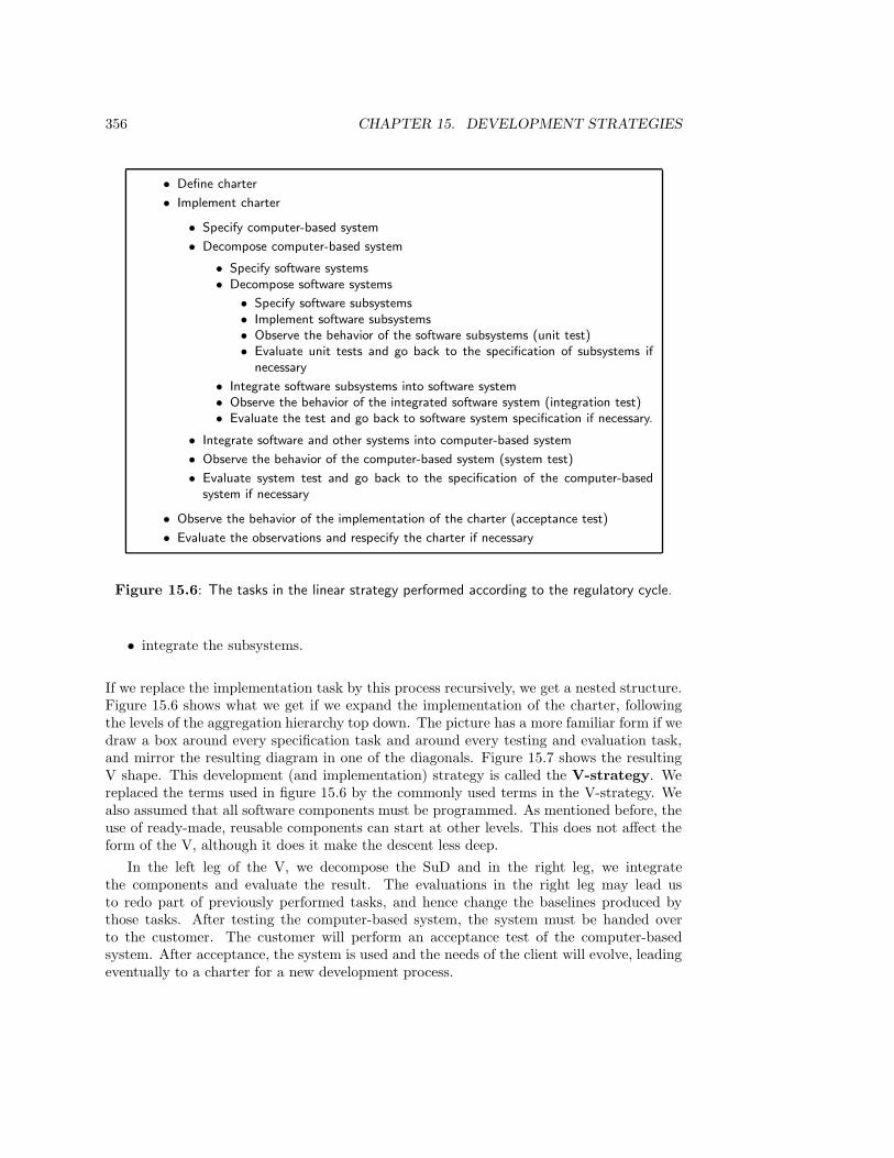
356 CHAPTER 15. DEVELOPMENT STRATEGIES
• Define charter
• Implement charter
• Specify computer-based system
• Decompose computer-based system
• Specify software systems• Decompose software systems
• Specify software subsystems• Implement software subsystems• Observe the behavior of the software subsystems (unit test)• Evaluate unit tests and go back to the specification of subsystems if
necessary
• Integrate software subsystems into software system• Observe the behavior of the integrated software system (integration test)• Evaluate the test and go back to software system specification if necessary.
• Integrate software and other systems into computer-based system
• Observe the behavior of the computer-based system (system test)
• Evaluate system test and go back to the specification of the computer-basedsystem if necessary
• Observe the behavior of the implementation of the charter (acceptance test)
• Evaluate the observations and respecify the charter if necessary
Figure 15.6: The tasks in the linear strategy performed according to the regulatory cycle.
• integrate the subsystems.
If we replace the implementation task by this process recursively, we get a nested structure.Figure 15.6 shows what we get if we expand the implementation of the charter, followingthe levels of the aggregation hierarchy top down. The picture has a more familiar form if wedraw a box around every specification task and around every testing and evaluation task,and mirror the resulting diagram in one of the diagonals. Figure 15.7 shows the resultingV shape. This development (and implementation) strategy is called the V-strategy. Wereplaced the terms used in figure 15.6 by the commonly used terms in the V-strategy. Wealso assumed that all software components must be programmed. As mentioned before, theuse of ready-made, reusable components can start at other levels. This does not affect theform of the V, although it does it make the descent less deep.
In the left leg of the V, we decompose the SuD and in the right leg, we integratethe components and evaluate the result. The evaluations in the right leg may lead usto redo part of previously performed tasks, and hence change the baselines produced bythose tasks. After testing the computer-based system, the system must be handed overto the customer. The customer will perform an acceptance test of the computer-basedsystem. After acceptance, the system is used and the needs of the client will evolve, leadingeventually to a charter for a new development process.
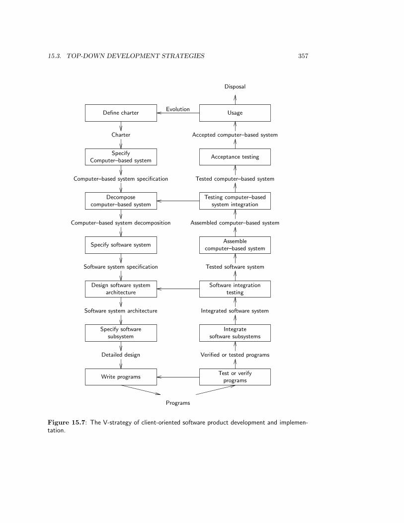
15.3. TOP-DOWN DEVELOPMENT STRATEGIES 357
Define charter UsageEvolution
Disposal
Charter Accepted computer–based system
SpecifyComputer–based system
Acceptance testing
Computer–based system specification Tested computer–based system
Decomposecomputer–based system
Testing computer–basedsystem integration
Computer–based system decomposition Assembled computer–based system
Specify software systemAssemble
computer–based system
Software system specification Tested software system
Design software systemarchitecture
Software integrationtesting
Software system architecture Integrated software system
Specify softwaresubsystem
Integratesoftware subsystems
Detailed design Verified or tested programs
Write programsTest or verify
programs
Programs
Figure 15.7: The V-strategy of client-oriented software product development and implemen-tation.

358 CHAPTER 15. DEVELOPMENT STRATEGIES
Evaluation of the V-strategy
The V-strategy has the advantage that it allows the definition of weak milestones andbaselines. Each stage deliverable in both legs of the V can turn into a baseline with theproviso that later testing may force us to improve or otherwise change the baseline. Thedisadvantage of the V-strategy is that the earlier an error is introduced, the later it isdiscovered. This can have devastating consequences. Empirical evidence suggests thatthe cost of repairing an error introduced in the system specification stage, but found inacceptance testing, can be 50 times as high as repairing that error in the system specificationstage itself. Repairing the error during “adaptive maintenance” may even be 1000 times asexpensive than the cost of repairing it in the system specification stage.
This disadvantage can be reduced if we perform every stage in the left leg of the Vaccording to the engineering cycle. That is, before we commit the deliverables of thestage, we simulate the stage deliverables, evaluate the result of this simulation, and iterateover these tasks until the quality of the stage deliverables is believed to be high enoughto warrant baselining them. The higher the quality of the simulations, the less frequenttesting will cause us to revise a baseline. An important technique for simulation is throw-away prototyping, discussed later.
15.4 A Framework for Concurrent Development
There is an important shift of perspective as we moved from the linear strategy to thesplashing waterfall and V-strategies. The boxes in the diagram of the linear strategy repre-sent stages which occur sequentially in time. On the other hand, the boxes in the diagramsof the splashing waterfall and V-strategies represent tasks, to which we can backtrack ifnecessary. The feedback arrows in figures 15.5 and 15.7 do not represent time travel, butindicate a possible path through a collection of tasks. We can clarify the situation if weseparate the logical tasks that have to be performed during development from the temporalstages of the development process. To do this, we return to the development framework ofchapter 3, extended with the implementation, observation and evaluation tasks of the reg-ulatory cycle (figure 15.8). Implementation of a software product consists of decomposingthe specification until ready-made executable parts are encountered, and integrating theseparts into a whole. Observation and evaluation are always lumped together under the termtesting. Figure 15.8 thus shows a framework for product development and implementation,using the engineering cycle and regulatory cycle at each level of aggregation. This extendedframework for product development and implementation still has two dimensions, aggre-gation and logic. We now turn it into the framework for concurrent engineering shown infigures 15.9 and 15.10 by adding the temporal dimension. To facilitate representation ona two-dimensional page, we merged the dimensions of aggregation and logic by stringingthe cells together in the order in which they are numbered in figure 15.8. These numbersalso appear in the vertical dimension of figures 15.9 and 15.10. The vertical dimension offigure 15.9 and 15.10 lists all logical product engineering tasks and the process managementtasks already shown in figure 15.1. The horizontal dimension lists the progression of stagesin time. To save space, we ignore the top layers of the aggregation hierarchy, and in orderto agree with accepted terminology the cells in the bottom row of figure 15.8 that deal withprogramming are merged.
The tasks performed in the V-strategy lie on the diagonal of the upper half of figure 15.9.
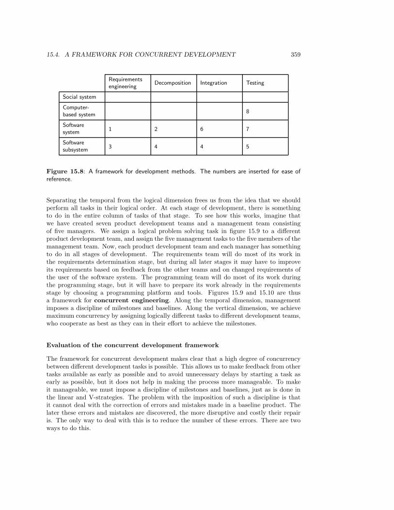
15.4. A FRAMEWORK FOR CONCURRENT DEVELOPMENT 359
Requirementsengineering
Decomposition Integration Testing
Social system
Computer-based system
8
Softwaresystem
1 2 6 7
Softwaresubsystem
3 4 4 5
Figure 15.8: A framework for development methods. The numbers are inserted for ease ofreference.
Separating the temporal from the logical dimension frees us from the idea that we shouldperform all tasks in their logical order. At each stage of development, there is somethingto do in the entire column of tasks of that stage. To see how this works, imagine thatwe have created seven product development teams and a management team consistingof five managers. We assign a logical problem solving task in figure 15.9 to a differentproduct development team, and assign the five management tasks to the five members of themanagement team. Now, each product development team and each manager has somethingto do in all stages of development. The requirements team will do most of its work inthe requirements determination stage, but during all later stages it may have to improveits requirements based on feedback from the other teams and on changed requirements ofthe user of the software system. The programming team will do most of its work duringthe programming stage, but it will have to prepare its work already in the requirementsstage by choosing a programming platform and tools. Figures 15.9 and 15.10 are thusa framework for concurrent engineering. Along the temporal dimension, managementimposes a discipline of milestones and baselines. Along the vertical dimension, we achievemaximum concurrency by assigning logically different tasks to different development teams,who cooperate as best as they can in their effort to achieve the milestones.
Evaluation of the concurrent development framework
The framework for concurrent development makes clear that a high degree of concurrencybetween different development tasks is possible. This allows us to make feedback from othertasks available as early as possible and to avoid unnecessary delays by starting a task asearly as possible, but it does not help in making the process more manageable. To makeit manageable, we must impose a discipline of milestones and baselines, just as is done inthe linear and V-strategies. The problem with the imposition of such a discipline is thatit cannot deal with the correction of errors and mistakes made in a baseline product. Thelater these errors and mistakes are discovered, the more disruptive and costly their repairis. The only way to deal with this is to reduce the number of these errors. There are twoways to do this.
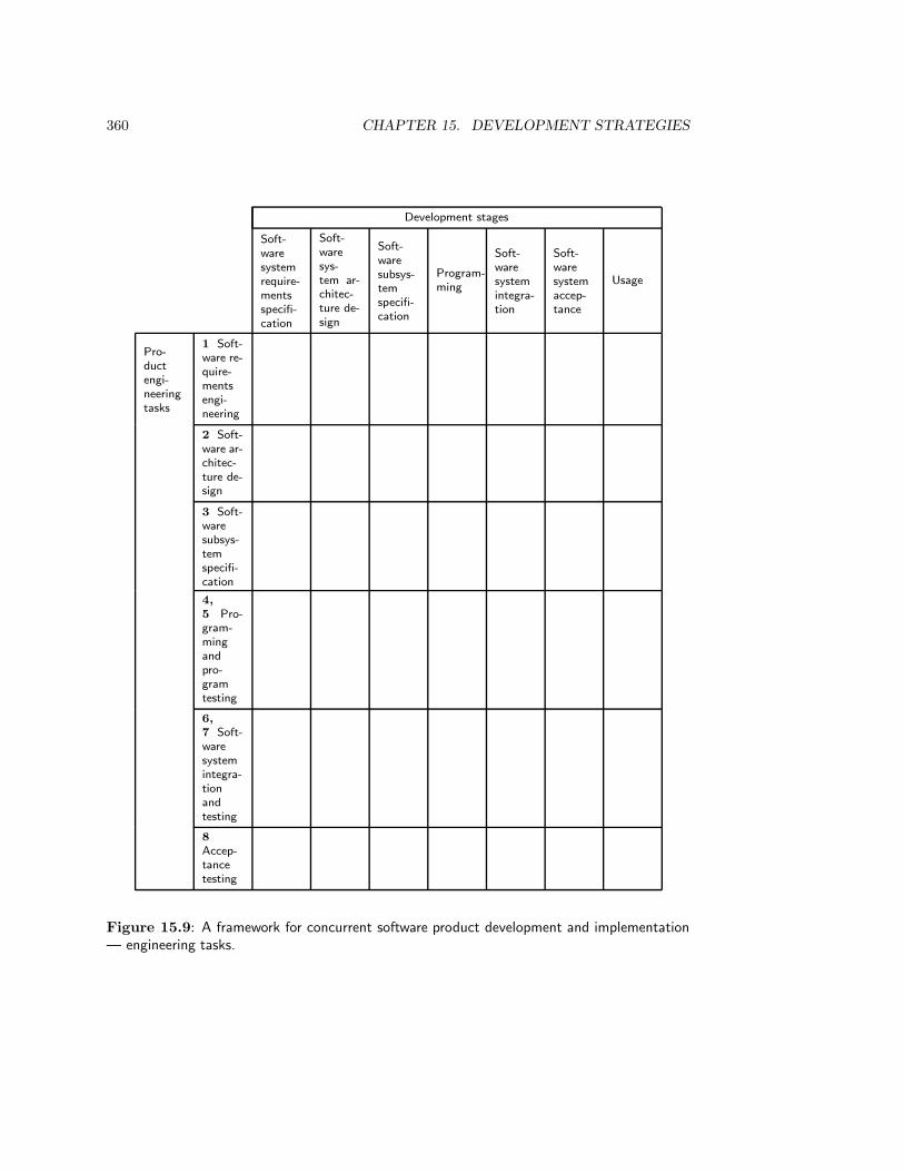
360 CHAPTER 15. DEVELOPMENT STRATEGIES
Development stages
Soft-
ware
system
require-
ments
specifi-
cation
Soft-
ware
sys-
tem ar-
chitec-
ture de-
sign
Soft-
ware
subsys-
tem
specifi-
cation
Program-
ming
Soft-
ware
system
integra-
tion
Soft-
ware
system
accep-
tance
Usage
Pro-
duct
engi-
neering
tasks
1 Soft-
ware re-
quire-
ments
engi-
neering
2 Soft-
ware ar-
chitec-
ture de-
sign
3 Soft-
ware
subsys-
tem
specifi-
cation
4,
5 Pro-
gram-
ming
and
pro-
gram
testing
6,
7 Soft-
ware
system
integra-
tion
and
testing
8
Accep-
tance
testing
Figure 15.9: A framework for concurrent software product development and implementation— engineering tasks.
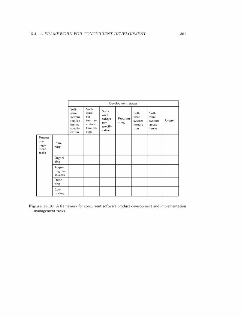
15.4. A FRAMEWORK FOR CONCURRENT DEVELOPMENT 361
Development stages
Soft-
ware
system
require-
ments
specifi-
cation
Soft-
ware
sys-
tem ar-
chitec-
ture de-
sign
Soft-
ware
subsys-
tem
specifi-
cation
Program-
ming
Soft-
ware
system
integra-
tion
Soft-
ware
system
accep-
tance
Usage
Process
ma-
nage-
ment
tasks
Plan-
ning
Organi-
zing
Acqui-
ring re-
sources
Direc-
ting
Con-
trolling
Figure 15.10: A framework for concurrent software product development and implementation— management tasks.
362 CHAPTER 15. DEVELOPMENT STRATEGIES
• Avoid errors and mistakes in a deliverable by producing the deliverable according tothe engineering cycle. That is, simulate the effect of the deliverable until confidenceis sufficiently high to permit commitment. Throw-away prototyping, discussed in thenext section, is a major technique for simulating software deliverables.
• Make the deliverables as small as possible, but not smaller. The smaller they are, theless errors they can contain, even without simulation. This leads to the strategy ofphased delivery, discussed in section 15.6.
15.5 Throw-away Prototyping
A product prototype is a system that displays some, but not all properties of the requiredproduct. Throw-away prototyping consists of producing a prototype of one of the alter-natives in an iteration through the engineering cycle. Throw-away prototyping is part ofthe essence of engineering, because its aim is to simulate the effects of an alternative beforethe alternative is implemented. It is not a strategy to implement a product, but a techniqueto gain knowledge about a product alternative in order to decide whether the alternativewill be implemented. The prototype need not be robust, well-structured, reliable or efficientas long as it allows us to learn more about how the alternative will behave before it is im-plemented. Any quick-and-dirty technique may be used, from Lisp programming to penciland paper simulations of a user interface. After evaluation of the prototype, the results areused in evaluation of the prototyped alternative and the prototype is discarded. Becausediscarding the prototype is essential, we always talk of throw-away prototyping instead ofjust prototyping.
Throw-away prototyping can be used in any of the problem solving tasks in productdevelopment, from the determination of requirements to the coding of programs. If usedat the early stages of development, a proof-of-concept prototype may be used to validate aproduct idea or to show the feasibility of a list of required product properties. In later stages,prototyping may be used to validate a product specification, to explore alternative systemdecompositions, to evaluate alternative user interfaces, to try out alternative algorithms,etc.
Evaluation of throw-away prototyping
Throw-away prototyping has a number of advantages:
• It increases certainty about the likely effects of an alternative before it is chosen. Itcan for example be used in the early stages of development to decrease requirementsuncertainty, i.e. to increase certainty that the acceptance test will not lead to drasticrevisions of the requirements.
• In client-oriented development, throw-away prototyping additionally helps reduce thecustomer’s and user’s uncertainty about what is possible and about what productthey can expect. This has two beneficial consequences:
– It makes it possible to reduce the number of changes in requirements after therequirements are committed.
– In addition, it makes it possible to enhance user support for the final product.
15.6. STRATEGIES FOR PHASED DEVELOPMENT 363
If the product is developed for a market, then similar advantages exist with respectto the marketing department.
Prototyping also has its dangers:
• It may distract the attention of the developer, customer or user from important fea-tures. Presented with a prototyped user interface, for example, users may spend alot of time evaluating the position of an icon on the screen but may ignore moreimportant features such as the flow of the dialogue.
• It takes time to develop a prototype, so throw-away prototyping may increase deve-lopment time. Some managers view time spent on coding a prototype as wasted time,because it is not spent on coding the final product. However, if used properly, timespent on throw-away prototyping is earned back by reduced backtracking later in thedevelopment process, and by a reduced need for corrective product maintenance. Ofcourse, time spent on generating throw-away prototypes should be minimized by usingprogram generators or other tools that allow fast production of software.
• The developer may become attached to the prototype, and start treating it as aportion of the end product. In client-oriented development, the customer or user toomay become attached to prototypes. This is a danger because a throw-away prototypeis usually produced without any attention to structure, safety, reliability, performance,etc. Software development managers should insist on discarding the prototype afteruse.
15.6 Strategies for Phased Development
The number of errors that creep through simulation can be further minimized by reducingthe size of the system under development. This means that we turn to phased deve-lopment, where we divide the system into portions to be developed successively. This iscontrasted with a monolithic development process, where the entire system is devel-oped in one shot. Any development process starts out as a monolithic process, in which aproduct idea is identified and product objectives are determined. However, at some pointduring the process, we can decide to select a portion of the product and develop that first,before developing other portions. Phased development strategies differ in the choice of themoment when they start dividing the product into portions. Some obvious possibilities arethe following:
• Determine product objectives globally without baselining them, and then performphased development. This is called evolutionary development. It is treated insubsection 15.6.2.
• Determine product objectives, baseline them, and then perform phased development.We don’t treat this strategy here.
• Determine product objectives, specify external product behavior, and then performphased development. This is called incremental development. It is treated insubsection 15.6.1.

364 CHAPTER 15. DEVELOPMENT STRATEGIES
• Determine product objectives, specify the product, decompose into subsystems, andthen deliver the subsystems by means of phased development. This is part of thecleanroom development strategy, not treated here.
15.6.1 Incremental development
In incremental development, we determine system objectives and specify required sys-tem behavior, baseline these deliverables, and then select a portion of the required func-tionality that promises to yield the best cost/benefit ratio [115]. This functionality is thenimplemented according to a linear strategy, V-strategy or concurrent strategy. After accep-tance testing of this portion of the product, another portion of the remaining functionalitywith the best expected cost/benefit ratio is selected, and this process iterates until the entireproduct is delivered. Each delivered portion of the product is called an increment.
Each increment is developed according to a traditional strategy. The tasks in the chosenstrategy can be performed according to the engineering cycle, so that throw-away proto-typing can be used at different stages in the development of an increment. The differencebetween incremental development and throw-away prototyping is that in incremental de-velopment a production-strength portion of a product is delivered, complete with errorrecovery procedures, input checking, exception-handling, required performance character-istics, hardware interface documentation, technical documentation, and user manuals. Inthrow-away prototyping, nothing is delivered, because the goal is the increase of knowledgeabout the requirements of the product.
Evaluation of incremental development
In incremental development, a version of the product is delivered early. This has a numberof advantages:
• The results of acceptance tests will be available earlier than they would be usinga monolithic development strategy. This means that errors in the product idea orrequirements specification can be spotted earlier than in the case of monolithic deve-lopment, and they will be cheaper to repair because the system is only delivered insmall increments.
• A working product is delivered earlier than it would be using a monolithic developmentstrategy. In client-oriented product development, this is reassuring for the customer aswell as for the user, who can become accustomed to the product. Product acceptanceis therefore enhanced.
Incremental development has two disadvantages:
• Errors introduced in the product objectives or requirements specification may not bediscovered until very late in the development process, because some of these may onlybecome apparent when the last increment of the product is delivered.
• Since the product architecture is defined incrementally, we may end up with no ar-chitecture at all. A bad product architecture leads to bad performance and badmaintainability of the product.

15.6. STRATEGIES FOR PHASED DEVELOPMENT 365
15.6.2 Evolutionary development
In evolutionary development, product objectives and behavior are specified globallyfirst, without baselining them. One portion of the requirements is then selected for furtherdevelopment, following the V-strategy. After development, experience with the deliveredportion of the product allows engineers and users to better understand the user needs andhence the product objectives, and to better understand feasible solutions to this needs andhence required product behavior. This is used to improve the objectives and the specificationof required behavior, and to select the next portion of the aspect of the product to bedeveloped and implemented.
There are two criteria that can be used to select a portion of the requirements to bedeveloped:
• As in incremental development, the expected cost/benefit ratio can be used.
• Alternatively, the part of the requirements about which the most certainty exists canbe chosen. This is a risk-avoidance strategy.
The difference between evolutionary and incremental development is that in evolutionarydevelopment a portion of the product is delivered before all required product behavioris specified. This means that the specification of external product behavior is writtenincrementally, as portions of the product are delivered. External product behavior is knownwith certainty only after the last increment has been specified. The difference with throw-away prototyping is, as before, that a production-strength portion of a product is delivered.In addition, in evolutionary prototyping, we may select the portion of the requirements tobe developed about which the most certainty is experienced. By contrast, in throw-awayprototyping, we select that portion about which the most uncertainty is experienced andabout which we want to learn more.
Evaluation of evolutionary development
Evolutionary development has the same advantages as incremental development: early de-livery of a portion of the product allows the developer to spot errors earlier and to repairspotted errors against lower cost than with monolithic development, and the user has aworking product sooner than with monolithic development, which enhances acceptance. Inaddition, it has a number of advantages that arise from the fact that part of the requirementsis specified after the first portion of the product is delivered.
• If only those requirements are selected for development about which most certainty isexperienced, then there is a high confidence that there are few errors in the require-ments.
• In client-oriented development, users have their hands on a version of the system early.In addition to increased user acceptance, this has two advantages:
– Users can adapt their requirements to what is feasible. These changes in require-ments are accommodated easily, because not all requirements are fixed at thestart of the process.

366 CHAPTER 15. DEVELOPMENT STRATEGIES
– Conversely, developers can learn more about user’s requirements, because expe-rience with the delivered portions of the product are available earlier and therequirements can still be adapted.
In market-oriented development, these advantages exist with respect to the marketingdepartment.
• Because requirements are kept global, conflicts over requirements are reduced. Fur-thermore, if the selected portions of the requirements are small enough, then they aretoo small to be worth battling over, and this reduces conflict as well. The result isreduced resistance to change. This advantage of the strategy is well-known in politicsand is often called salami tactics, because change is implemented slice by slice.
Evolutionary development also has a number of important disadvantages:
• Since only global requirements are specified, the developer may not even have a consis-tent product idea. Again, this is a well-known phenomenon in politics: salami tacticsmay be a substitute for having a vision rather than a way to carefully implement avision. Reacting to events like user dissatisfaction can be done with only short-termgoals in mind and requires no vision.
• As with incremental development, the system architecture is specified incrementally.This may lead to a bad architecture and its concomitant maintenance and performanceproblems. Because the requirements specification is produced incrementally as well,coherence of this specification may be low as well, resulting in even less coherence ofthe product.
• It is not clear when to stop evolutionary development. When is development finishedand does perfective maintenance start? The rule is that when the architecture ofa system gets corrupted to the extent that maintenance becomes a problem, a newsystem must be developed. However, evolutionary development may result in a systemwith a bad architecture to begin with.
Figure 15.11 summarizes the properties of throw-away prototyping, incremental develop-ment and evolutionary development. Note that throw-away prototyping can be combinedwith either of the other two, but that incremental and evolutionary development are mutu-ally exclusive.
15.6.3 Experimental development
In experimental development, a prototype is delivered for real use. Evaluation then maylead to an improvement of the delivered prototype or to an update of the requirements.The difference with throw-away prototyping is that the prototype is actually used. Thedifference with incremental and evolutionary development is that a prototype rather than aproduction-strength system is delivered.
Experimental development is a departure from the engineering cycle, because it dropsthe idea that an alternative must be evaluated before it is chosen. Experimental developmentis suitable only for research environments.

15.6. STRATEGIES FOR PHASED DEVELOPMENT 367
Throw-away prototypingof requirements
Incremental developmentCertainty-drivenevolutionary development
Increases cer-tainty of devel-opers about re-quirements
Requirements errors spot-ted earlier
Requirements errors spot-ted earlier
Prevents requirements er-rors
Avoid requirements errors
Less product errors to re-pair
Product errors cheaper torepair
Product errors cheaper torepair
Increase cer-tainty of clientsor marketingabout product
Prevent changes in re-quirements
Accommodate changes inrequirements
Enhance user support Enhance user support Enhance user support
DangersPossibleattention to unimportantdetails
Errors in product specifi-cation discovered late
There may be no productidea
Takes timeDevelopment process maynot terminate
Prototype may be used asfinished product
Possibly bad product ar-chitecture
Possibly bad product ar-chitecture
Figure 15.11: Properties of throw-away prototyping and two phased development strategies.
368 CHAPTER 15. DEVELOPMENT STRATEGIES
15.7 Rational Reconstruction of the Development Pro-cess
The framework for concurrent product development and implementation is really three-dimensional, the three dimensions being aggregation, logic and time. There is an importantrelationship between the logical and temporal dimensions. We have used the logical di-mension to analyze requirements engineering methods in part II of this book. The logicaldimension has a second use, viz. as a template for a rational justification of a result, afterthe result is produced. We give two illustrations of this.
• In the engineering cycle, we produce a justification for a design decision by listingthe alternatives considered, their likely effects, and the evaluations of these effectsagainst the product objectives. Estimation of the likely effects of an alternative canbe backed up by a simulation in the form of a throw-away prototype, an informalargument, observation of similar systems elsewhere, etc.
• In the empirical cycle, we produce a justification of a modeling decision by listing thealternatives considered, their observable consequences, and the results of experimentsin which these consequences are falsified or verified. The experiments may consist ofsimple observations, interviews with domain specialists, etc.
Obviously, one is in a very good position to produce these justifications if one actuallyfollowed the empirical and engineering cycles. However, the developer has more freedomthan this. In order to produce these justifications after development, all that is requiredis that during development, a record of development is constructed that takes the form ofthese justifications. Development is then just as much the specification of a product asit is the construction of justifications for these specifications. We call this the rationalreconstruction of the development process. As time goes by, we record the alternatives,their consequences and the evaluation of these consequences, independently from the orderin which these were considered. The alternatives may have been considered at differentpoints in time and after many backtrackings, but they appear on the record as if they wereall considered during one iteration through the rational problem solving cycle.
Recording the considered alternatives not only helps us justify the result of development,but also helps us to accommodate changes in available technology, client needs, objectives orpreferences. When alternatives and their simulations and evaluations have been recorded,then it will be easier to reconsider choices made in the light of the new situation. Forexample, if available technology drops in price and we remember that an otherwise promisingalternative was rejected because it was estimated to be too expensive, then an opportunityarises to choose this previously rejected alternative. If we had not recorded the reasons forrejecting this alternative, this opportunity might not have become visible. Recording thealternatives considered and their simulations and evaluations is thus an important tool torealize backward traceability of specifications to the reasons why they were chosen over otherspecifications.
Summing up, rational problem solving now has four useful roles to play:
• As a tool to analyze development methods.
• As a tool for structuring the decision making process.
15.8. SUMMARY 369
• As a tool for justifying the results of development.
• As a tool to allow us to reconsider of alternatives when circumstances change.
Rational reconstruction of a sometimes erratic real-world process occurs in many otherareas where a historical process must be explained and justified in a rational way. Thebibliographical remarks give some pointers to the literature.
15.8 Summary
There are two kinds of tasks in the development and implementation of a product, productengineering tasks and process management tasks. The product engineering tasks are require-ments engineering, decomposition, integration and testing. The process management tasksare planning, organizing, acquisition, directing and controlling the development process.
An important class of methods for planning the development process is the class ofmethods to select a development strategy for the process. There are a number of different top-down strategies, in which we descend top-down in the aggregation hierarchy. In the linearor waterfall strategy, we descend top-down in the aggregation hierarchy without permittingbacktracking. This is a developer’s nightmare, because errors cannot be corrected, but amanager’s dream, because a strict discipline of milestones and baselines is enforced. If weallow backtracking to the previous task, then we get the splashing waterfall strategy, which isa developer’s dream but a manager’s nightmare, because no stage deliverable is committeduntil all are committed. If we perform every task in the linear strategy according to theregulatory cycle, and allow backtracking if evaluation shows that the system contains anerror, then we get the V-strategy of system development. The V-strategy allows a disciplineof milestones and baselines, restricted by the possibility to renegotiate earlier baselines.
In the framework for concurrent engineering, tasks and stages of development have beenseparated, and all tasks are allowed to be performed in all stages. This freedom is limitedby the choice of milestones by process management.
During any execution of the engineering cycle, at any level of aggregation, we may de-cide to simulate an alternative by building a throw-away prototype. Throw-away prototypesare not intended for real use. Rather, their purpose is to learn something about a decisionalternative and after they have served this purpose, they are discarded. Throw-away proto-typing has the advantage that it increases the certainty of the prediction of the effect of analternative, that it involves users and therefore increases acceptance of the final product,and that it can be used in the requirements stage to achieve more certainty about require-ments and let users formulate more realistic requirements. It has the disadvantages that itmay distract the attention of users and developers from essential features, that it takes timeand resources to develop a prototype, and that the developer or user may become attachedto the prototype and starts using it as if it were a production-strength product.
Another strategy option, independent from the choice of top-down strategies and ofthrow-away prototyping, is whether or not to deliver a system in stages. In incrementaldevelopment, the requirements specification is developed top down, and the system is thendelivered incrementally with increasing functionality. Usually, the increments are selectedusing a cost/benefit criterion. In evolutionary development, the requirements are determinedglobally but not baselined, and portions of the requirements are then developed in stages.As a consequence, parts of the requirements are worked out further only after the first
370 CHAPTER 15. DEVELOPMENT STRATEGIES
increment is delivered. Usually, the portion of the requirements developed further is theone about which the developers are most certain. The advantages and disadvantages ofphased development are summarized in figure 15.11.
In experimental development, a prototype is delivered for real use and updated as re-quired by experience. The difference with throw-away prototyping is that the prototype isnot thrown away; the difference with incremental and evolutionary development is that aprototype is delivered rather than a production-strength product. Experimental develop-ment is a departure from the engineering cycle, because a product alternative is evaluatedby using it, not before using it.
All these strategies allow a rational reconstruction of the development process as ifthe engineering cycle were followed. This allows the developer to justify the results ofdevelopment. Maintaining a record of all alternatives considered and their simulationsand evaluations also helps in accommodating changes that inevitably occur during or afterdevelopment.
15.9 Exercises
1. Number the boxes in the V-strategy and write these numbers in the correspondingcells of figure 15.8.
2. (a) Change the V-strategy by generalizing it to software as well as non-softwareproduct development.
(b) Change the V-strategy by turning it into a strategy for market-driven develop-ment.
3. Classify the following tasks by allocating them to one or more cells in figures 15.9or 15.10. If necessary, add product development tasks or development stages to thetable.
(a) Determining a plan for acceptance testing of a software system.
(b) Estimating the need for development resources and their cost.
(c) Writing a user’s manual.
(d) Investigation of algorithms.
(e) Documentation of programs.
(f) Training system users.
(g) Selection of a programming language and supporting tools.
(h) Definition of interfaces between subsystems.
4. Enumerate as many ways to simulate a software product as you can imagine, inaddition to throw-away prototyping.
5. In The Wheelwright’s Shop (Cambridge University Press, 1923), George Sturt, a crafts-man himself, describes nineteenth-century traditional wagon-making. The followingdescription of this process is based on the summary by Jones [168, pages 15–20].
Wagon craftsmen were very intimate with the peculiarities of the neighborhood, suchas the nature of the soil in a farm, the gradient of a hill, or the type of horses used
15.10. BIBLIOGRAPHICAL REMARKS 371
by a customer. The dimensions of a wagon, the timber used, the curves followed andmany other details of a wagon were tailored to these conditions of use. Knowledgeabout the design of a wagon was not written down nor represented in drawings. Itwas spread out in a network of country prejudices and discussed over and over againin village workshops and farmyards. For centuries, these details were passed downfrom father to son. Most of it was a mystery. Because nobody knew the reasons fordesign decisions, changes to a design were only made locally, for example by choosinga slightly different “dish” (the angle with which a wheel slopes outward) or choosinga different kind of wood. Over the centuries, this trial-and-error process led to awell-balanced design and a close fit to user needs.
Compare this account with
(a) evolutionary development and
(b) experimental development.
6. Appendix C lists the stages and tasks of ETHICS. Although the lists have beenordered sequentially, not all methods recommend sequential performance of all thesetasks. When we refer to “sequences” of tasks in what follows, this refers to sequencesin the presentation of the methods, not necessarily in the performance of the methods.For each of the methods, do the following:
(a) Separate product development tasks from process management tasks.
(b) For the product development tasks, partition the method into groups of taskssuch that each group is concerned with one level of aggregation in the aggregationhierarchy of figure 15.8.
(c) For each of the groups so identified, try if you can map the tasks in the group toparticular tasks in the engineering cycle and/or to the regulatory cycle.
7. Answer the questions of exercise 6 for SSADM (appendix C). In part (b) look alsofor decomposition tasks that bring us to the next lower level of aggregation.
15.10 Bibliographical Remarks
Process management. Useful introductions to process management are given by South-well [322] and by Rook [288]. One of the best introductions to software process managementis Rook [287]. Thayer [341] gather together an important collection of papers on softwareproject management. Figure 15.2 is based on an overview paper by Thayer [342]. Theconcept of the universality of management is taken as point of departure in that paper.Thayer uses the breakdown of management tasks proposed by Mackenzie [206] and used,with a slight alteration, in figures 15.1 and 15.2. Boehm [40] gives a survey of managementissues for software projects. Thayer and Pyster edited a special issue of the IEEE Trans-actions on Software Engineering on software project management [344]. Humphrey [152]gives well-rounded and influential view on managing the development process with a viewto realizing continual improvement.
372 CHAPTER 15. DEVELOPMENT STRATEGIES
Top-down strategies. The regulatory cycle is a model of rational action taken fromthe field of social theory [329] and process consultancy [184]. It allows us to understandthe relation between the V model of the software process and the engineering cycle. The Vmodel was introduced by Jensen and Tonies [165]. It is used by Rook [287] and the STARTSGuide [240]. McDermid [222] contains an extensive treatment of the V model and its placein software process modeling. The classic source for the waterfall strategy is Royce [295], apaper that is still worth reading. It was popularized by Boehm [36] and used by Boehm [37]in his COCOMO model for estimating the cost of software products. A conveniently briefintroduction to the waterfall strategy, with a summary of advantages and disadvantages,is given by Agresti [4]. Jones [168, page 75] lists all the strategies considered here in thecontext of industrial product engineering.
Framework for concurrent engineering. The matrix of stages against tasks of de-velopment is introduced by Rook [287]. Variations are given by McDermid [222] and bythe STARTS Guide [240]. In all three sources, the cells of the matrix are filled in withthe activities that a task generates during a stage. A very similar framework for the soft-ware engineering process is given by Peters and Tripp [258, 257]. As pointed out in thebibliographical remarks of chapter 3, the intellectual ancestor of these frameworks is a three-dimensional framework for the systems engineering process given by Hall [133]. In additionto the temporal and logical dimensions (stages and tasks), Hall used the aspect dimensionmentioned in subsection 3.6.3 to represent the kind of knowledge that we use in systemdevelopment.
A motivation for concurrent engineering in product development is given by Sprague,Singh and Wood [324]. Concurrent engineering is often combined with integrated develop-ment, also called total product design, in which marketing, engineering, design, manufactur-ing, sales and management personnel work together during the entire development processto develop a product specification. Concurrent engineering and integrated development aretwo important ingredients in Quality Function Deployment [54].
Empirical studies of the development process. In empirical studies done by Guin-don [128] show that developers jump from task to task in an opportunistic way until thedesign is finished, i.e. until they have a requirements specification with a corresponding im-plementation. Empirical studies done by Zelkowitz [382] show that half of a system design isusually done after the formal design stage is finished, and that coding starts during designand continues until acceptance testing. A study by Visser [351] confirms these findings.These studies all concern the behavior of individual engineers; I am not aware of studies oftask sequencing in project groups.
Parnas and Clements [255] give many reasons why a rational development process cannotbe followed in practice. Among others, designers have limited time, preconceived ideasabout how the product should be designed, make mistakes, have problems mastering themountain of details involved in an engineering project, may be forced to reuse software thatthey cannot really use, etc. Swartout and Balzer [334] give an example that illustrates howthe specification of a data structure may be influenced by implementation considerations.
Rational reconstruction. The concept of rational reconstruction has been introducedby Carnap [60] and was further developed by Reichenbach [277, 278]. Reichenbach remarks
15.10. BIBLIOGRAPHICAL REMARKS 373
that logic governs the result of thinking, not the process of thinking itself. Once we havethe result, we construct a chain of thoughts from the starting point to the point of arrival toexplain and justify the result to others. It is this rational reconstruction that is governed bythe laws of logic, not the process of thinking itself [278, page 2]. Accordingly, Reichenbachdistinguishes the context of discovery from the context of justification. Transferring thisargument to the development process, we can speak about the context of development andthe context of justification. The selection of a development strategy is part of the contextof development, rational problem solving and the rational engineering methods are part ofthe context of justification.
Suchman [330, 331] gives an interesting description of the role of rational reconstructionin office procedures. The actual course of events in an office is too unpredictable and chaoticto be captured by a procedure that takes care of all errors, like invoices received for the wrongamount, for missing orders, etc. Errors are left unstated in the formal office procedures.When an error occurs, office personnel engages in an activity in which they try to find outwhich sequence of events should have happened, and they then try to construct this historyafter the fact. They contact the sender of the invoice, they copy missing data from otherdepartments, etc. This constructed history is a rational reconstruction of actual history,and it is the history they record in the books. This is not a falsification of history but arational reconstruction of history as it would have taken place when the world would havebeen ideal. In this way, office employees take responsibility for what happened in the office,and it is the only way they can take responsibility for it [331, pages 326–327]. This doesnot mean that office workers “fake” the appearance of orderliness in the records. Rather,the construction of orderly records is the construction of evidence of action in accordancewith the procedures. Computer scientists too easily look upon these procedures as if theywere computer programs to be followed by office workers, just as they construe developmentmethods as programs to be followed by themselves.
The difference between the logic of problem solving and the historical stages of a problemsolving process is illustrated by management decision making too. As remarked in thebibliographical remarks of chapter 3, Mintzberg, Raisinghani and Theoret [234] found thatmanagers do not blindly follow through the rational problem solving process step by step,but choose a path through it that may skip tasks that are easy or for which there is notime, and that may iterate over tasks that are important for the problem at hand. In otherwords, the actual process usually differs from the rational process, but after the fact it canbe rationally reconstructed as a number of iterations through the rational process.
Turning to software development, Parnas and Clements [255] advocate what they call“faking” a rational software development process by constructing a record of the develop-ment process as if it followed a rational procedures. From what has been said above, itshould be clear that this is not faking in a bad sense. Rather, the construction of a recordof a rational development process is the means by which software developers justify the re-sult of development to others and take responsibility for it. The importance of justificationof design decisions in software development has recently been pointed out by Potts andBruns [265]. The importance of recording reasons of requirements for the reconsiderationof design decisions when circumstances change is pointed out by Gause and Weinberg [111,page 271].
Rational reconstruction was a big issue in the philosophy of science in the beginning ofthe 1970s. Very roughly, where Popper [264] studied the logic of scientific discovery andKuhn [186] studied the history of scientific discovery, Lakatos [187] saw the logical structure

374 CHAPTER 15. DEVELOPMENT STRATEGIES
of scientific discovery as a rational reconstruction of its history. (Of course, philosopherswould not be philosophers if they did not disagree about what the logic of discovery actuallyis.)
Throw-away prototyping. Prototyping as an approach to software development wasproposed at least as early as the mid-1970s. However, prototyping became popular only inthe beginning of the 1980s; the Software Engineering Notes has a special issue on proto-typing in December 1982 (volume 7, number 5). Carey and Mason [58] note that softwareprofessionals will frequently state that they have been working this way for ages — whichis to be expected, because throw-away prototyping belongs to the essence of engineering.Another interesting observation made by Carey and Mason is that authors of papers onprototyping rarely quote each other, and that the origin of prototyping is either attributedto folklore or to the author’s invention.
In the first half of the 1980s, throw-away prototyping and evolutionary development werenot distinguished. The distinction is made very clear by Davis [78]. Gomaa [121] describesthe effect of throw-away prototyping and evolutionary development on the system develop-ment process. Alavi [7] provides empirical evidence for the increase of user involvementand user satisfaction by means of throw-away prototyping. Alavi and Wetherbe [8] showin an experiment with students that throw-away prototyping preceded by data modelingyields better results in fewer iterations than throw-away prototyping not preceded by datamodeling.
Useful surveys of prototyping are given by Agresti [5] and Ince [155]. Both authorsargue that executable formal specification languages can be used to produce throw-awayrequirements prototypes. This argument confuses throw-away prototypes with evolutionaryversions of the product. In a recent status report on prototyping, Luqi and Royce [205] cor-rectly argue that a language for throw-away prototyping does not need to provide facilitiesfor verifying correctness and completeness of a design or implementation, as a specificationlanguage does. Gordon and Bieman [123] provide a comprehensive survey of case studies ofthrow-away and evolutionary prototyping and their effects on software product quality anddevelopment process quality. Almost all case studies report that both forms of prototypingresult in increased ease of use of the software product, a better match with user needs,reduced system development effort and increased user participation.
A short and interesting defense of the usefulness of throw-away prototyping is given byAndriole [10]. He argues that throw-away prototyping is always cost-effective and alwaysimproves specifications. Interestingly, he recommends using multiattribute evaluation tech-niques for evaluating throw-away prototypes, similar to the techniques used in evaluatingalternative product designs in industrial development.
Incremental development. An early reference to the incremental development strategyis Basili and Turner [24]. Distaso [88] attributes the idea of incremental development toWilliams [367]. Dyer [93] gives an early report on its use at IBM is Incremental developmentwas adopted by IBM as a software development strategy. Boehm [37, page 42] recommendsit as an improvement on the monolithic application of the waterfall strategy. He points outthat the major effect of incremental development on the software development process is aflattening of the distribution of labor over time.
15.10. BIBLIOGRAPHICAL REMARKS 375
Cleanroom development. One ingredient of cleanroom development is phased develop-ment, starting from an architecture of the system. The other ingredients of the cleanroomstrategy are separation of programming and testing (programmers do not execute their pro-grams), combined with formal correctness proofs of programs by their programmers [195],and statistical usage testing of programs by testers [73]. Cleanroom development is de-scribed by Linger [196] and Selby, Basili and Baker [306].
Evolutionary development. Evolutionary development is really an example of a well-known strategy known as “salami tactics” to politicians and “muddling through” to man-agers. The classic paper on muddling through is Lindblom [193], which should be mandatoryreading for all software engineering students. The basic assumption of Lindblom is that ad-ministrators, politicians and managers must solve problems with a state space so large andof a complexity so vast that there is no reliable abstraction in terms of which they can an-alyze the situation and explore alternative solutions. And even if there were such a model,they do not have the time to commission a study to solve these problems and wait for itsresults. Consequently, instead of analyzing the situation, they try to remember a similarsituation from the past and then do something that differs only marginally from what wasdone in that earlier situation. In evolutionary development too, developers deliver a newversion of a product that differs only marginally from the current version and they do thisfor the same reason: they are not able to predict the consequences of any radical changeto the current version. If they could, then they should practice engineering, i.e. simulateand evaluate product alternatives before they are implemented. The advantages and disad-vantages of evolutionary development given in section 15.6 are all derived from Lindblom’spaper.
In software engineering, evolutionary development is championed by Gilb [114, 115],who also calls it design by objectives. This is derived from the Lindblom’s argument for“salami tactics” in the face of complex problems, as well as from the idea of managementby objectives (MBO), introduced by Drucker [92].
Another important defense of the evolutionary strategy is given by McCracken andJackson [221]. Their major argument against the linear development strategy is that thevery process of developing a system will change the requirements; this is the principleof requirements uncertainty. Dearnley and Mayhew [83] give a brief introduction to theevolutionary strategy.
Boehm [43] provides empirical evidence for the relative advantages and disadvantagesof waterfall development and evolutionary development with respect to each other. Ina perceptive discussion of this result, Davis [77, page 348] remarks that the prototypeproduced in the experiment did not have any documentation and had no requirementsspecified for them. It is therefore more like a throw-away prototype than an evolutionaryproduct.
Luqi and Royce [205] argue that evolutionary prototyping would benefit from softwarereuse, because that would allow faster production of a production-strength software system.They observe that, unfortunately, evolutionary development is needed most in those areasthat are least understood. For these areas, it is likely that little reusable software is available.

Chapter 16
Selecting a DevelopmentStrategy
16.1 Introduction
The previous chapter should have made it clear that no strategy is suitable for all types ofdevelopment situations. In this chapter, we discuss two methods for selecting a developmentstrategy for a particular development process, Boehm’s spiral method (section 16.2) and thepart of Euromethod that is concerned with selecting development strategies (section 16.3).
16.2 The Spiral Model for Software Development
The spiral model of software development proposed by Boehm [39, 42] is a method to adaptthe development strategy dynamically to the changing pattern of risks that arise during thedevelopment process. According to Webster’s [356], a risk is a possibility of loss or injury.In the context of product development, a risk is the possibility of not getting sufficientbenefits from the product to justify the cost of developing it.
16.2.1 Structure
Boehm published several versions of his spiral model, the most recent of which is shown infigure 16.1 [35, 41]. The process iterates over four tasks. During each iteration, a portionof the product is developed. In the first task, the objectives of this portion of the productare determined, alternative strategies of developing it are generated, and constraints onthese strategies are determined. In the second task, the alternative strategies are evaluatedon the risk of developing a wrong product and the alternative is chosen with the greatestreduction of this risk. In the third task, the portion of the product is developed following theselected strategy. This takes us one or more steps further down the aggregation hierarchyand possibly yields a finished portion of the product. In the fourth task, the developmentis reported about and the next iteration through the spiral is planned.
The innovation of this process is the determination of the development strategy bymeans of an engineering cycle, in which risk is minimized. The spiral process is thus an
377
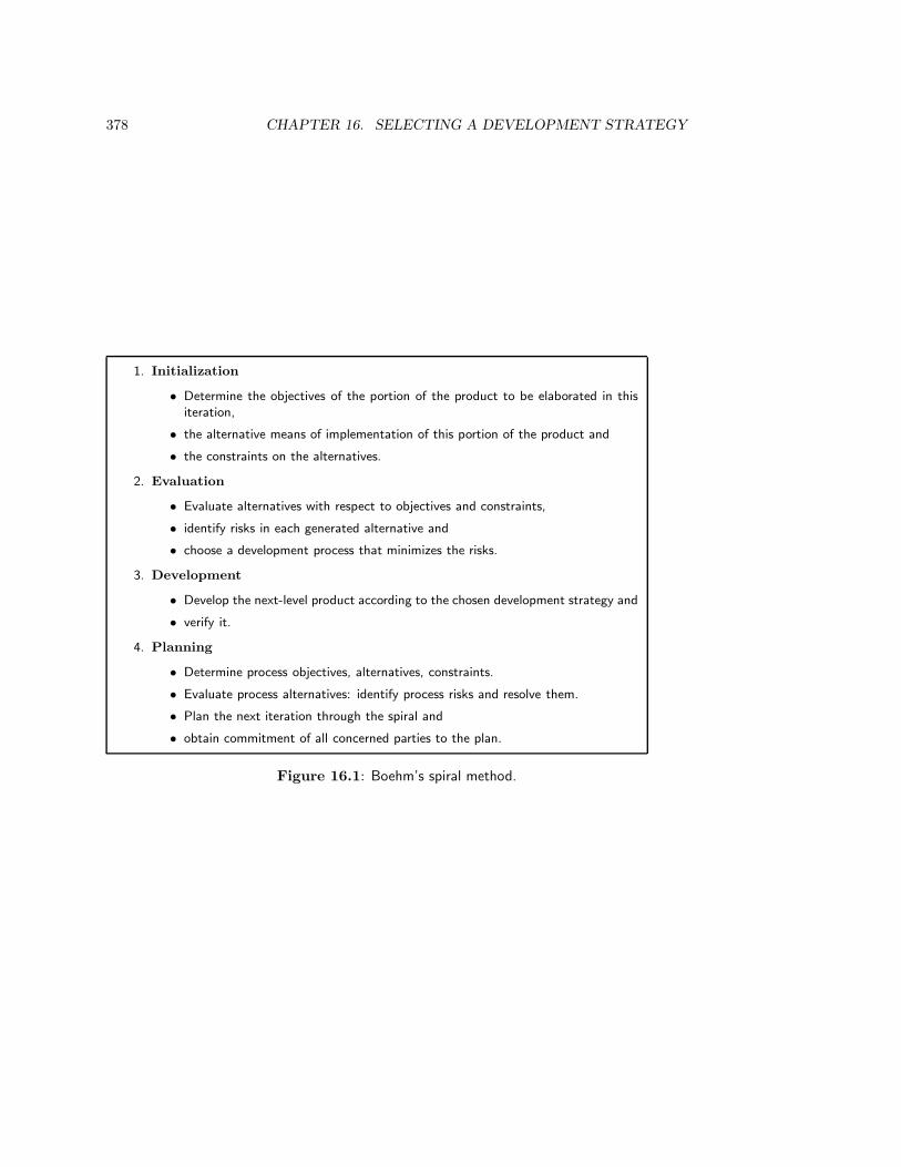
378 CHAPTER 16. SELECTING A DEVELOPMENT STRATEGY
1. Initialization
• Determine the objectives of the portion of the product to be elaborated in thisiteration,
• the alternative means of implementation of this portion of the product and
• the constraints on the alternatives.
2. Evaluation
• Evaluate alternatives with respect to objectives and constraints,
• identify risks in each generated alternative and
• choose a development process that minimizes the risks.
3. Development
• Develop the next-level product according to the chosen development strategy and
• verify it.
4. Planning
• Determine process objectives, alternatives, constraints.
• Evaluate process alternatives: identify process risks and resolve them.
• Plan the next iteration through the spiral and
• obtain commitment of all concerned parties to the plan.
Figure 16.1: Boehm’s spiral method.

16.2. THE SPIRAL MODEL FOR SOFTWARE DEVELOPMENT 379
Analysis
Process engineering
Synthesis
Simulation
Evaluation
Choice
Analysis
Product engineering
Synthesis
Simulation
Evaluation
Choice
Figure 16.2: The logical structure of the spiral method.
interleaving of process engineering with product engineering tasks (figure 16.2). In an initialprocess engineering task, we select a strategy and then perform one iteration through theproduct engineering cycle. This reduces uncertainty about the product, for example bydescending one level of the system aggregation hierarchy. This reduced uncertainty maycause us to redo the process engineering cycle, because the risk analysis in the new situationmay differ from the previous risk analysis. The first task of the spiral method covers theanalysis and synthesis tasks of process engineering. The second task covers simulation,evaluation and choice of strategy, and the third task consists of product development. Thefourth task is a process management task (planning) and is not visible in figure 16.2.
Figure 16.2 makes clear that the spiral strategy is a generalization of all strategiesdiscussed in chapter 15. In all these strategies, there is one initial process engineering taskfollowed by a number of iterations over product engineering. In the spiral strategy, we mayreturn to process engineering after every iteration over the product development process.
16.2.2 Strategies
During the process engineering stage, we generate a number of alternative developmentstrategies. The following strategies are recognized by the spiral method.
• One of the simplest development strategies is to buy commercial off-the-shelf soft-ware, called COTS by Boehm. (The very simplest process is, of course, not to dodevelopment at all.)
• Transformational development is the development of a software product by suc-
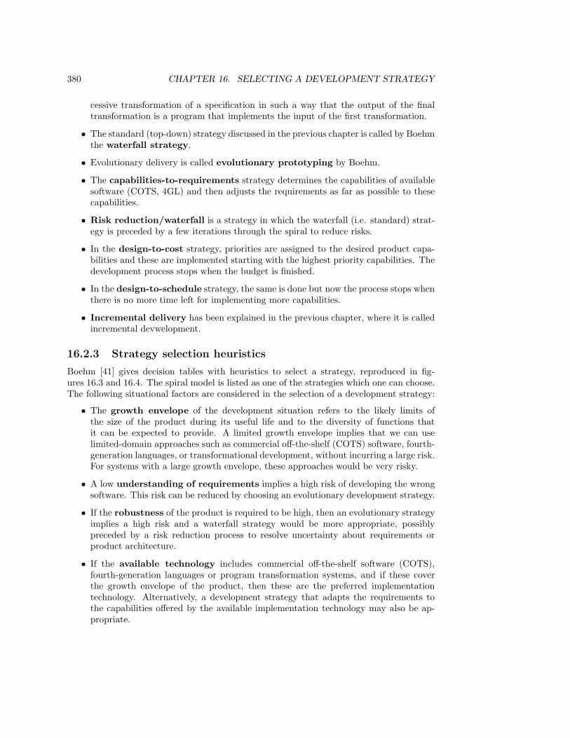
380 CHAPTER 16. SELECTING A DEVELOPMENT STRATEGY
cessive transformation of a specification in such a way that the output of the finaltransformation is a program that implements the input of the first transformation.
• The standard (top-down) strategy discussed in the previous chapter is called by Boehmthe waterfall strategy.
• Evolutionary delivery is called evolutionary prototyping by Boehm.
• The capabilities-to-requirements strategy determines the capabilities of availablesoftware (COTS, 4GL) and then adjusts the requirements as far as possible to thesecapabilities.
• Risk reduction/waterfall is a strategy in which the waterfall (i.e. standard) strat-egy is preceded by a few iterations through the spiral to reduce risks.
• In the design-to-cost strategy, priorities are assigned to the desired product capa-bilities and these are implemented starting with the highest priority capabilities. Thedevelopment process stops when the budget is finished.
• In the design-to-schedule strategy, the same is done but now the process stops whenthere is no more time left for implementing more capabilities.
• Incremental delivery has been explained in the previous chapter, where it is calledincremental devwelopment.
16.2.3 Strategy selection heuristics
Boehm [41] gives decision tables with heuristics to select a strategy, reproduced in fig-ures 16.3 and 16.4. The spiral model is listed as one of the strategies which one can choose.The following situational factors are considered in the selection of a development strategy:
• The growth envelope of the development situation refers to the likely limits ofthe size of the product during its useful life and to the diversity of functions thatit can be expected to provide. A limited growth envelope implies that we can uselimited-domain approaches such as commercial off-the-shelf (COTS) software, fourth-generation languages, or transformational development, without incurring a large risk.For systems with a large growth envelope, these approaches would be very risky.
• A low understanding of requirements implies a high risk of developing the wrongsoftware. This risk can be reduced by choosing an evolutionary development strategy.
• If the robustness of the product is required to be high, then an evolutionary strategyimplies a high risk and a waterfall strategy would be more appropriate, possiblypreceded by a risk reduction process to resolve uncertainty about requirements orproduct architecture.
• If the available technology includes commercial off-the-shelf software (COTS),fourth-generation languages or program transformation systems, and if these coverthe growth envelope of the product, then these are the preferred implementationtechnology. Alternatively, a development strategy that adapts the requirements tothe capabilities offered by the available implementation technology may also be ap-propriate.
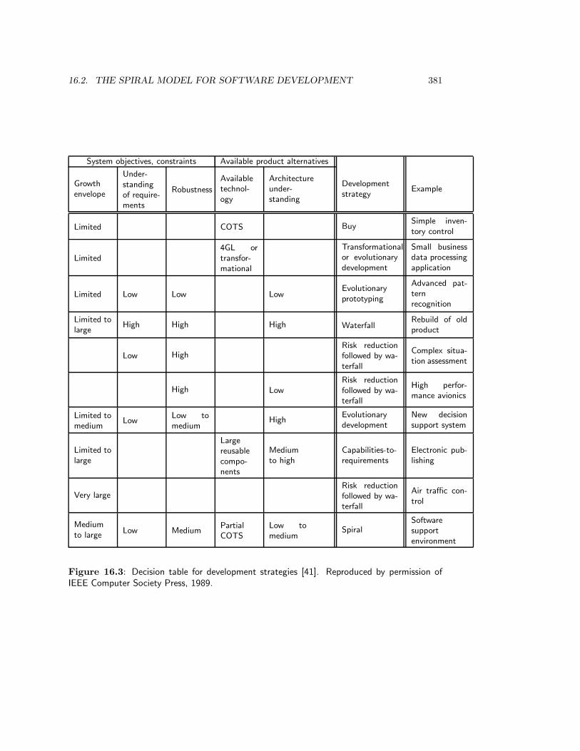
16.2. THE SPIRAL MODEL FOR SOFTWARE DEVELOPMENT 381
System objectives, constraints Available product alternatives
Growthenvelope
Under-standingof require-ments
Robustness
Availabletechnol-ogy
Architectureunder-standing
Developmentstrategy
Example
Limited COTS BuySimple inven-tory control
Limited4GL ortransfor-mational
Transformationalor evolutionarydevelopment
Small businessdata processingapplication
Limited Low Low LowEvolutionaryprototyping
Advanced pat-ternrecognition
Limited tolarge
High High High WaterfallRebuild of oldproduct
Low HighRisk reductionfollowed by wa-terfall
Complex situa-tion assessment
High LowRisk reductionfollowed by wa-terfall
High perfor-mance avionics
Limited tomedium
LowLow tomedium
HighEvolutionarydevelopment
New decisionsupport system
Limited tolarge
Largereusablecompo-nents
Mediumto high
Capabilities-to-requirements
Electronic pub-lishing
Very largeRisk reductionfollowed by wa-terfall
Air traffic con-trol
Mediumto large
Low MediumPartialCOTS
Low tomedium
SpiralSoftwaresupportenvironment
Figure 16.3: Decision table for development strategies [41]. Reproduced by permission ofIEEE Computer Society Press, 1989.
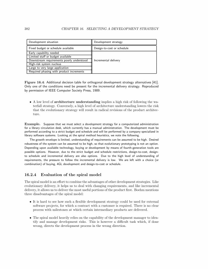
382 CHAPTER 16. SELECTING A DEVELOPMENT STRATEGY
Development situation Development strategy
Fixed budget or schedule available Design-to-cost or schedule
Early capability neededLimited staff or budget availableDownstream requirements poorly understood Incremental deliveryHigh-risk system nucleusLarge to very large applicationRequired phasing with product increments
Figure 16.4: Additional decision table for orthogonal development strategy alternatives [41].Only one of the conditions need be present for the incremental delivery strategy. Reproducedby permission of IEEE Computer Society Press, 1989.
• A low level of architecture understanding implies a high risk of following the wa-terfall strategy. Conversely, a high level of architecture understanding lowers the riskthat the evolutionary strategy will result in radical revisions of the product architec-ture.
Example. Suppose that we must select a development strategy for a computerized administrationfor a library circulation desk, which currently has a manual administration. The development must beperformed according to a strict budget and schedule and will be performed by a company specialized inlibrary software systems. Looking at the spiral method heuristics, we note the following.
The growth envelope is limited, understanding of requirements can be assumed to be high. Desired
robustness of the system can be assumed to be high, so that evolutionary prototyping is not an option.
Depending upon available technology, buying or development by means of fourth-generation tools are
possible options. However, due to the strict budget and schedule restrictions, design-to-cost, design-
to schedule and incremental delivery are also options. Due to the high level of understanding of
requirements, the pressure to follow the incremental delivery is low. We are left with a choice (or
combination) of buying, 4GL development and design-to-cost or schedule.
16.2.4 Evaluation of the spiral model
The spiral model is an effort to combine the advantages of other development strategies. Likeevolutionary delivery, it helps us to deal with changing requirements, and like incrementaldelivery, it allows us to deliver the most useful portions of the product first. Boehm mentionsthree disadvantages of the spiral model:
• It is hard to see how such a flexible development strategy could be used for externalsoftware projects, for which a contract with a customer is required. There is no clearprocess with milestones at which certain intermediary products are delivered.
• The spiral model heavily relies on the capability of the development manager to iden-tify and manage development risks. This is however a difficult task which, if donewrong, directs the development process in the wrong direction.
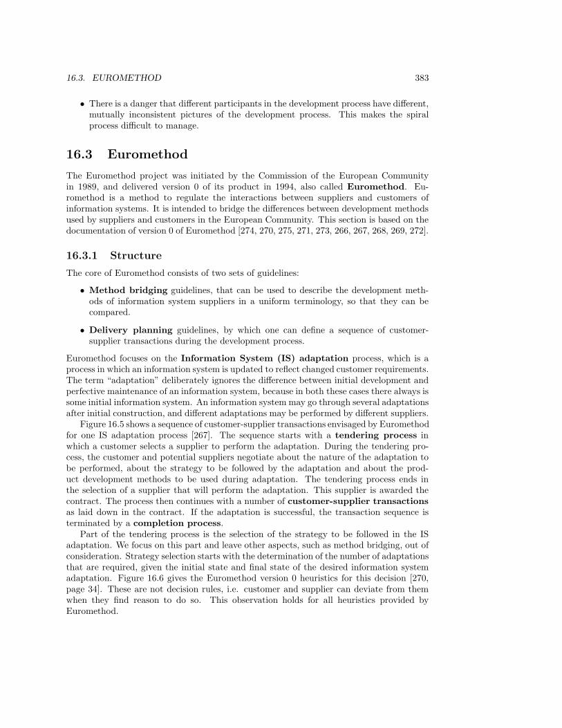
16.3. EUROMETHOD 383
• There is a danger that different participants in the development process have different,mutually inconsistent pictures of the development process. This makes the spiralprocess difficult to manage.
16.3 Euromethod
The Euromethod project was initiated by the Commission of the European Communityin 1989, and delivered version 0 of its product in 1994, also called Euromethod. Eu-romethod is a method to regulate the interactions between suppliers and customers ofinformation systems. It is intended to bridge the differences between development methodsused by suppliers and customers in the European Community. This section is based on thedocumentation of version 0 of Euromethod [274, 270, 275, 271, 273, 266, 267, 268, 269, 272].
16.3.1 Structure
The core of Euromethod consists of two sets of guidelines:
• Method bridging guidelines, that can be used to describe the development meth-ods of information system suppliers in a uniform terminology, so that they can becompared.
• Delivery planning guidelines, by which one can define a sequence of customer-supplier transactions during the development process.
Euromethod focuses on the Information System (IS) adaptation process, which is aprocess in which an information system is updated to reflect changed customer requirements.The term “adaptation” deliberately ignores the difference between initial development andperfective maintenance of an information system, because in both these cases there always issome initial information system. An information system may go through several adaptationsafter initial construction, and different adaptations may be performed by different suppliers.
Figure 16.5 shows a sequence of customer-supplier transactions envisaged by Euromethodfor one IS adaptation process [267]. The sequence starts with a tendering process inwhich a customer selects a supplier to perform the adaptation. During the tendering pro-cess, the customer and potential suppliers negotiate about the nature of the adaptation tobe performed, about the strategy to be followed by the adaptation and about the prod-uct development methods to be used during adaptation. The tendering process ends inthe selection of a supplier that will perform the adaptation. This supplier is awarded thecontract. The process then continues with a number of customer-supplier transactionsas laid down in the contract. If the adaptation is successful, the transaction sequence isterminated by a completion process.
Part of the tendering process is the selection of the strategy to be followed in the ISadaptation. We focus on this part and leave other aspects, such as method bridging, out ofconsideration. Strategy selection starts with the determination of the number of adaptationsthat are required, given the initial state and final state of the desired information systemadaptation. Figure 16.6 gives the Euromethod version 0 heuristics for this decision [270,page 34]. These are not decision rules, i.e. customer and supplier can deviate from themwhen they find reason to do so. This observation holds for all heuristics provided byEuromethod.
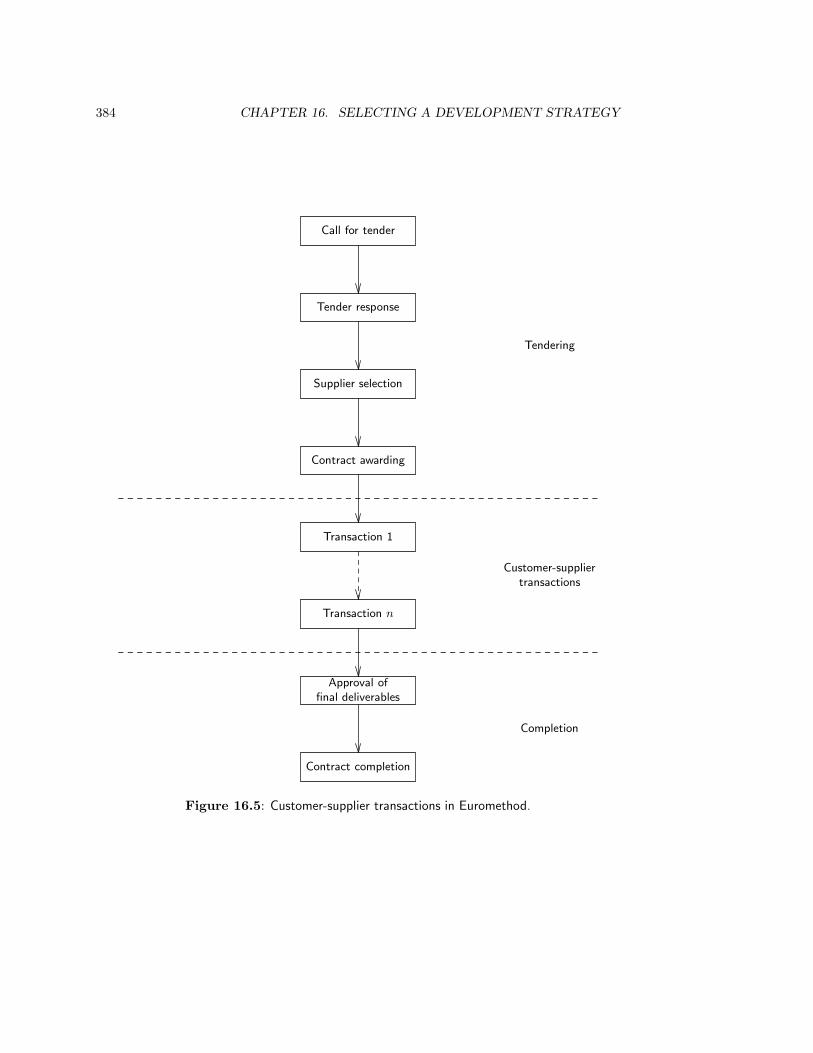
384 CHAPTER 16. SELECTING A DEVELOPMENT STRATEGY
Call for tender
Tender response
Tendering
Supplier selection
Contract awarding
Transaction 1
Customer-suppliertransactions
Transaction n
Approval offinal deliverables
Completion
Contract completion
Figure 16.5: Customer-supplier transactions in Euromethod.
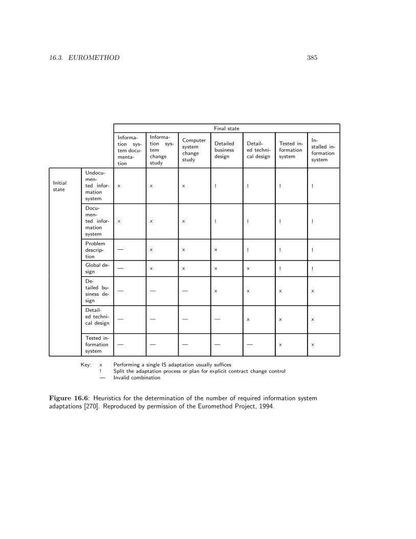
16.3. EUROMETHOD 385
Final state
Informa-
tion sys-
tem docu-
menta-
tion
Informa-
tion sys-
tem
change
study
Computer
system
change
study
Detailed
business
design
Detail-
ed techni-
cal design
Tested in-
formation
system
In-
stalled in-
formation
system
Initial
state
Undocu-
men-
ted infor-
mation
system
x x x ! ! ! !
Docu-
men-
ted infor-
mation
system
x x x ! ! ! !
Problem
descrip-
tion
— x x x ! ! !
Global de-
sign— x x x x ! !
De-
tailed bu-
siness de-
sign
— — — x x x x
Detail-
ed techni-
cal design— — — — x x x
Tested in-
formation
system
— — — — — x x
Key: x Performing a single IS adaptation usually suffices
! Split the adaptation process or plan for explicit contract change control
— Invalid combination
Figure 16.6: Heuristics for the determination of the number of required information systemadaptations [270]. Reproduced by permission of the Euromethod Project, 1994.

386 CHAPTER 16. SELECTING A DEVELOPMENT STRATEGY
16.3.2 Strategies
For each adaptation process, a situational analysis is performed to determine the strategy tobe followed during the adaptation. The definition of a strategy results in the definition of asequence of customer-supplier transactions that must be executed during the adaptation. Ineach transaction, deliverables are exchanged between supplier and customer and, possibly,the contract between supplier and customer is renegotiated.
Euromethod distinguishes four approaches for which a strategic option must be se-lected [269, pages 36–47]:
• The system description strategy options are to use an analytical mode of descrip-tion, in which the developers write documents that specify system behavior, or else touse the experimental mode of description, in which developers perform experimentsto learn about the system. Independently from this the developers have the option tofollow an expert-driven cooperation mode, in which they produce descriptions of thesystem based on interviews and observations of system users, or to follow a partici-patory mode, in which users or their representatives are included in the developmentprocess.
• The system construction options are one-shot, incremental and evolutionary con-struction. The concepts are the same as those introduced in chapter 15 but with aslightly different terminology:
– In one-shot construction, the system is constructed and tested as a whole.
– In incremental construction, requirements of the system are determined firstand the system is then constructed and tested incrementally.
– In evolutionary construction, the system is constructed and tested in suc-cessive versions. Between two versions, the requirements can be changed afterlearning from system testing.
• The system installation options are linear, incremental and evolutionary installa-tion.
– In one-shot installation, the entire system is installed at once. The systemmay be constructed using a one-shot, incremental, or evolutionary strategy.
– In incremental installation, the system is installed in portions. Requirementsto the system are fixed before the first installation. This approach can be com-bined with one-shot construction as well as with incremental construction, andit can be combined with evolutionary construction if before the first installation,we evolve the requirements to the point where we can fix them.
– In evolutionary installation, the system is installed in successive versions andthe requirements to the system can change after the first installation and betweensuccessive installations. This approach can be combined with evolutionary con-struction but not with one-shot or incremental construction.
• Project control. There are three groups of choices to be made:
– Development control. A choice can be made between frequent or infrequentcustomer-supplier transactions, between formal and informal control procedures,
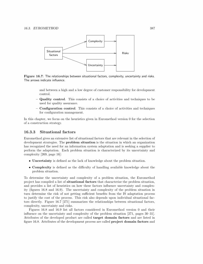
16.3. EUROMETHOD 387
Situationalfactors
Complexity
Uncertainty
Risks
Figure 16.7: The relationships between situational factors, complexity, uncertainty and risks.The arrows indicate influence.
and between a high and a low degree of customer responsibility for developmentcontrol.
– Quality control. This consists of a choice of activities and techniques to beused for quality assurance.
– Configuration control. This consists of a choice of activities and techniquesfor configuration management.
In this chapter, we focus on the heuristics given in Euromethod version 0 for the selectionof a construction strategy.
16.3.3 Situational factors
Euromethod gives an extensive list of situational factors that are relevant in the selection ofdevelopment strategies. The problem situation is the situation in which an organizationhas recognized the need for an information system adaptation and is seeking a supplier toperform the adaptation. Each problem situation is characterized by its uncertainty andcomplexity [269, page 16]:
• Uncertainty is defined as the lack of knowledge about the problem situation.
• Complexity is defined as the difficulty of handling available knowledge about theproblem situation.
To determine the uncertainty and complexity of a problem situation, the Euromethodproject has compiled a list of situational factors that characterize the problem situation,and provides a list of heuristics on how these factors influence uncertainty and complex-ity (figures 16.8 and 16.9). The uncertainty and complexity of the problem situation inturn determine the risk of not getting sufficient benefits from the IS adaptation processto justify the cost of the process. This risk also depends upon individual situational fac-tors directly. Figure 16.7 [271] summarizes the relationships between situational factors,complexity, uncertainty and risks.
Figures 16.8 and 16.9 list all factors considered in Euromethod version 0 and theirinfluence on the uncertainty and complexity of the problem situation [271, pages 30–31].Attributes of the developed product are called target domain factors and are listed infigure 16.8. Attributes of the development process are called project domain factors and
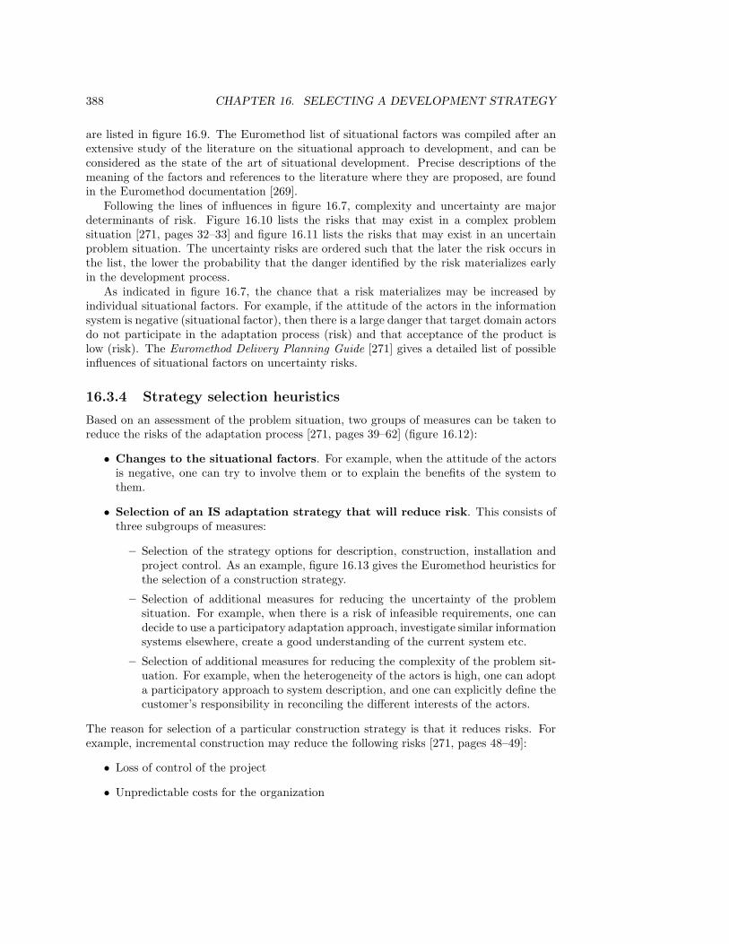
388 CHAPTER 16. SELECTING A DEVELOPMENT STRATEGY
are listed in figure 16.9. The Euromethod list of situational factors was compiled after anextensive study of the literature on the situational approach to development, and can beconsidered as the state of the art of situational development. Precise descriptions of themeaning of the factors and references to the literature where they are proposed, are foundin the Euromethod documentation [269].
Following the lines of influences in figure 16.7, complexity and uncertainty are majordeterminants of risk. Figure 16.10 lists the risks that may exist in a complex problemsituation [271, pages 32–33] and figure 16.11 lists the risks that may exist in an uncertainproblem situation. The uncertainty risks are ordered such that the later the risk occurs inthe list, the lower the probability that the danger identified by the risk materializes earlyin the development process.
As indicated in figure 16.7, the chance that a risk materializes may be increased byindividual situational factors. For example, if the attitude of the actors in the informationsystem is negative (situational factor), then there is a large danger that target domain actorsdo not participate in the adaptation process (risk) and that acceptance of the product islow (risk). The Euromethod Delivery Planning Guide [271] gives a detailed list of possibleinfluences of situational factors on uncertainty risks.
16.3.4 Strategy selection heuristics
Based on an assessment of the problem situation, two groups of measures can be taken toreduce the risks of the adaptation process [271, pages 39–62] (figure 16.12):
• Changes to the situational factors. For example, when the attitude of the actorsis negative, one can try to involve them or to explain the benefits of the system tothem.
• Selection of an IS adaptation strategy that will reduce risk. This consists ofthree subgroups of measures:
– Selection of the strategy options for description, construction, installation andproject control. As an example, figure 16.13 gives the Euromethod heuristics forthe selection of a construction strategy.
– Selection of additional measures for reducing the uncertainty of the problemsituation. For example, when there is a risk of infeasible requirements, one candecide to use a participatory adaptation approach, investigate similar informationsystems elsewhere, create a good understanding of the current system etc.
– Selection of additional measures for reducing the complexity of the problem sit-uation. For example, when the heterogeneity of the actors is high, one can adopta participatory approach to system description, and one can explicitly define thecustomer’s responsibility in reconciling the different interests of the actors.
The reason for selection of a particular construction strategy is that it reduces risks. Forexample, incremental construction may reduce the following risks [271, pages 48–49]:
• Loss of control of the project
• Unpredictable costs for the organization
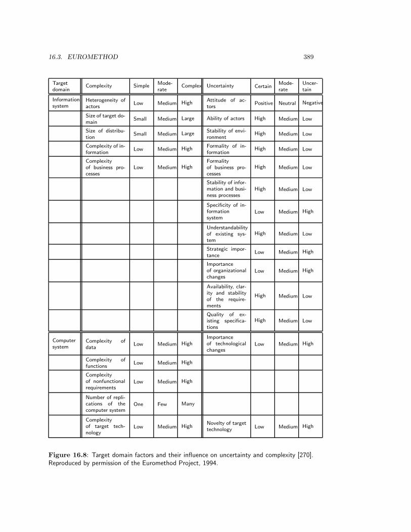
16.3. EUROMETHOD 389
Target
domainComplexity Simple
Mode-
rateComplex Uncertainty Certain
Mode-
rate
Uncer-
tain
Information
systemHeterogeneity of
actorsLow Medium High
Attitude of ac-
torsPositive Neutral Negative
Size of target do-
mainSmall Medium Large Ability of actors High Medium Low
Size of distribu-
tionSmall Medium Large
Stability of envi-
ronmentHigh Medium Low
Complexity of in-
formationLow Medium High
Formality of in-
formationHigh Medium Low
Complexity
of business pro-
cesses
Low Medium HighFormality
of business pro-
cesses
High Medium Low
Stability of infor-
mation and busi-
ness processes
High Medium Low
Specificity of in-
formation
systemLow Medium High
Understandability
of existing sys-
tem
High Medium Low
Strategic impor-
tanceLow Medium High
Importance
of organizational
changesLow Medium High
Availability, clar-
ity and stability
of the require-
ments
High Medium Low
Quality of ex-
isting specifica-
tions
High Medium Low
Computer
systemComplexity of
dataLow Medium High
Importance
of technological
changesLow Medium High
Complexity of
functionsLow Medium High
Complexity
of nonfunctional
requirementsLow Medium High
Number of repli-
cations of the
computer systemOne Few Many
Complexity
of target tech-
nologyLow Medium High
Novelty of target
technologyLow Medium High
Figure 16.8: Target domain factors and their influence on uncertainty and complexity [270].Reproduced by permission of the Euromethod Project, 1994.

390 CHAPTER 16. SELECTING A DEVELOPMENT STRATEGY
Project
domainComplexity Simple
Mode-
rateComplex Uncertainty Certain
Mode-
rate
Uncer-
tain
Project
taskSize of project Small Medium Large
Novelty of IS ap-
plicationLow Medium High
Complexity of
migrationLow Medium High
Adequacy of
schedules— Normal Tight
Adequacy of
budget— Normal Tight
Project
structure
Number of sub-
contractorsNone Few Many
Dependency on
subcontractorsNone Low High
Number of inter-
faces to other IS
adaptationsNone Few Many
Dependency on
other IS adapta-
tions
None Low High
Formality of
customer-
supplier context
High Medium Low
Project
actors
Number of
project actorsSmall Medium Large
Capability
of project actors High Medium Low
Project
technol-
ogy
Complexity
of development
technologyLow Medium High
Novelty of deve-
lopment technol-
ogyLow Medium High
Availability of
appropriate de-
velopment tech-
nology
High Medium Low
Figure 16.9: Project domain factors and their influence on uncertainty and complexity [270].Reproduced by permission of the Euromethod Project, 1994.
• Loss of control of the project
• The information system is not working
• The information system is not capable of dealing with the complexity of its targetdomain (i.e. with the complexity of its UoD or of its immediate environment).
Figure 16.10: Complexity risks identified by Euromethod [270]. Reproduced by permission ofthe Euromethod Project, 1994.

16.3. EUROMETHOD 391
• Uncertain or unfeasible requirements
• Uncertain interfaces to other systems
• Evolving requirements
• Unpredictable costs for the organization
• Unpredictable costs for the project
• Lack of target domain actor participation (e.g. lack of participation by users, domainspecialists or customer representatives)
• Technical shortfalls in externally performed tasks
• Delays in the delivery of products.
• Poor quality of products
• Increased cost of the project
• Integration problems
• Shortfalls in nonfunctional properties
• Straining computer science capabilities
• Developing the wrong system or an unfeasible system
• The information system adaptation is not accepted by the IS-actors (e.g. by users orthe customer)
• Business implications of project failure
Figure 16.11: Uncertainty risks identified by Euromethod [270]. Reproduced by permissionof the Euromethod Project, 1994.
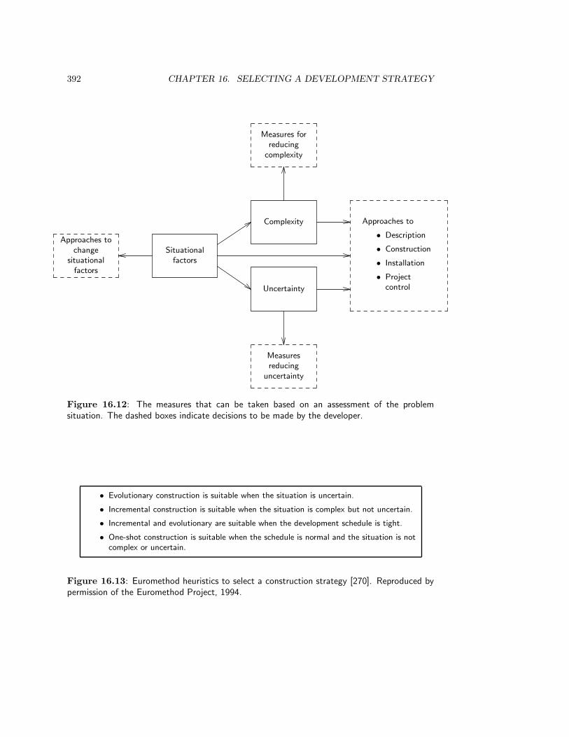
392 CHAPTER 16. SELECTING A DEVELOPMENT STRATEGY
Situationalfactors
Complexity
Uncertainty
Approaches to
• Description
• Construction
• Installation
• Projectcontrol
Approaches tochange
situationalfactors
Measures forreducing
complexity
Measuresreducing
uncertainty
Figure 16.12: The measures that can be taken based on an assessment of the problemsituation. The dashed boxes indicate decisions to be made by the developer.
• Evolutionary construction is suitable when the situation is uncertain.
• Incremental construction is suitable when the situation is complex but not uncertain.
• Incremental and evolutionary are suitable when the development schedule is tight.
• One-shot construction is suitable when the schedule is normal and the situation is notcomplex or uncertain.
Figure 16.13: Euromethod heuristics to select a construction strategy [270]. Reproduced bypermission of the Euromethod Project, 1994.

16.3. EUROMETHOD 393
• Unpredictable costs for the project
• Poor quality of products
• Increased cost of the project
• Integration problems
• Shortfalls in nonfunctional properties
Evolutionary construction may reduce the following risks:
• Uncertain or unfeasible requirements
• Uncertain interfaces to other systems
• Evolving requirements
• Unpredictable costs for the project
• Delays in the delivery of products
• Poor quality of products
• Increased cost of the project
• Integration problems
• Shortfalls in nonfunctional properties
• Straining computer science capabilities
• Developing the wrong system or an unfeasible system
Example. We take the same development situation as in the spiral method example, the develop-ment of a computerized administration for a library circulation desk, which currently has a manualadministration. The development must be performed according to a strict budget and schedule andwill be performed by a company specialized in library software systems. Looking at the Euromethodheuristics, we note the following.
The initial state is an undocumented information system and the final state is an installed informationsystem. According to figure 16.6, this should be split into several adaptation processes. However,because the problem is well-understood (some software vendors specialize in library administrationsystems) and the customer can be expected to be able to state his requirements, a single adaptationprocess is decided.
Looking at the target domain factors, we see that the information system complexity factors all
score on the simple side and that most information system uncertainty factors score on the certain side.
However, the strategic importance of the system is high and the quality of existing specifications is low,
which increases the uncertainty about the system. The complexity and uncertainty of the computer
system are low. Project domain factors all tend towards low complexity and low uncertainty, except the
adequacy of budget and schedules, which tends to high uncertainty. Due to the high level of experience
of the software companies doing the development, a one-shot construction strategy is decided.
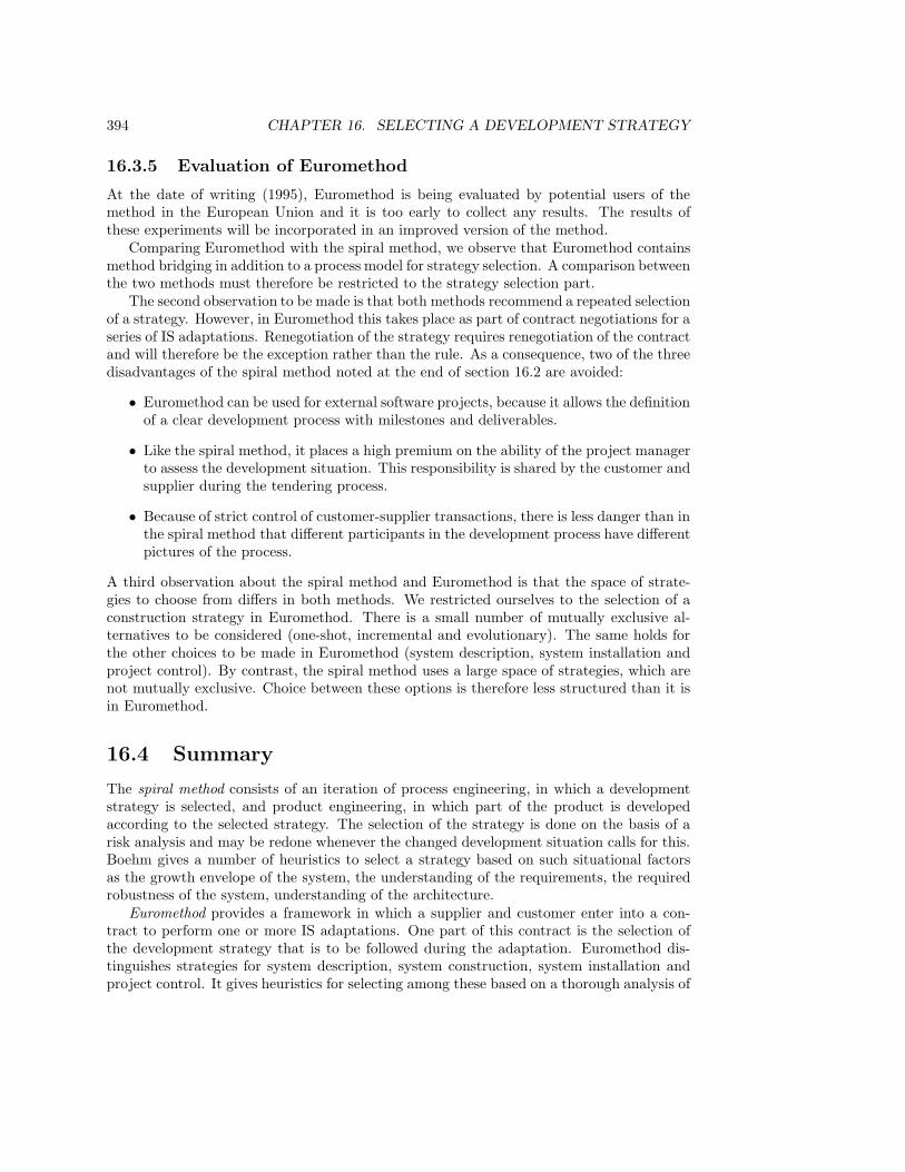
394 CHAPTER 16. SELECTING A DEVELOPMENT STRATEGY
16.3.5 Evaluation of Euromethod
At the date of writing (1995), Euromethod is being evaluated by potential users of themethod in the European Union and it is too early to collect any results. The results ofthese experiments will be incorporated in an improved version of the method.
Comparing Euromethod with the spiral method, we observe that Euromethod containsmethod bridging in addition to a process model for strategy selection. A comparison betweenthe two methods must therefore be restricted to the strategy selection part.
The second observation to be made is that both methods recommend a repeated selectionof a strategy. However, in Euromethod this takes place as part of contract negotiations for aseries of IS adaptations. Renegotiation of the strategy requires renegotiation of the contractand will therefore be the exception rather than the rule. As a consequence, two of the threedisadvantages of the spiral method noted at the end of section 16.2 are avoided:
• Euromethod can be used for external software projects, because it allows the definitionof a clear development process with milestones and deliverables.
• Like the spiral method, it places a high premium on the ability of the project managerto assess the development situation. This responsibility is shared by the customer andsupplier during the tendering process.
• Because of strict control of customer-supplier transactions, there is less danger than inthe spiral method that different participants in the development process have differentpictures of the process.
A third observation about the spiral method and Euromethod is that the space of strate-gies to choose from differs in both methods. We restricted ourselves to the selection of aconstruction strategy in Euromethod. There is a small number of mutually exclusive al-ternatives to be considered (one-shot, incremental and evolutionary). The same holds forthe other choices to be made in Euromethod (system description, system installation andproject control). By contrast, the spiral method uses a large space of strategies, which arenot mutually exclusive. Choice between these options is therefore less structured than it isin Euromethod.
16.4 Summary
The spiral method consists of an iteration of process engineering, in which a developmentstrategy is selected, and product engineering, in which part of the product is developedaccording to the selected strategy. The selection of the strategy is done on the basis of arisk analysis and may be redone whenever the changed development situation calls for this.Boehm gives a number of heuristics to select a strategy based on such situational factorsas the growth envelope of the system, the understanding of the requirements, the requiredrobustness of the system, understanding of the architecture.
Euromethod provides a framework in which a supplier and customer enter into a con-tract to perform one or more IS adaptations. One part of this contract is the selection ofthe development strategy that is to be followed during the adaptation. Euromethod dis-tinguishes strategies for system description, system construction, system installation andproject control. It gives heuristics for selecting among these based on a thorough analysis of
16.5. EXERCISES 395
situational factors. The situational factors are partitioned into target domain and projectdomain factors and include those identified by Boehm. Euromethod also gives heuristicsto change these factors or to reduce the uncertainty and complexity that arises from thesefactors.
16.5 Exercises
1. Map the logical structure of the spiral method (figure 16.2) to the structure of thespiral method (figure 16.1).
2. Explain the strategy selection heuristics given by Boehm (figures 16.3 and 16.4).
3. Explain the construction strategy selection heuristics of Euromethod (figure 16.13).
4. Use the heuristics given in figure 16.13 to construct a decision table that recommends aconstruction strategy for each possible combination of values for the situational factorsschedule, complexity and certainty. The possible values for each of these factors areschedule ∈ {normal, tight}, complexity ∈ {simple, moderate, complex} and uncertainty∈ {certain, moderate, uncertain}.
5. For each of the following situations, select a development strategy according to thespiral method heuristics and according to the Euromethod heuristics. In the case ofEuromethod, recommend the number of IS adaptations to be performed. Motivatethe choices you make and explain the differences between the selected strategies, ifany.
(a) The improvement of an elevator control system currently implemented in a sys-tem of electromagnetic switches, by a company that produces elevator systems.The system should be able to control several elevators such that they jointly giveoptimal service to the elevator users.
(b) The development of an EDI system that connects the different local police de-partments in The Netherlands. In the past, each department has, independentlyfrom other departments, automatized some of its administrative tasks. The de-sired EDI network should allow uniform exchange of information about incidents(e.g. traffic accidents, burglaries) and persons (e.g. violators, criminals). Flexi-bility should be built in to allow smooth transition to integration into a Europeannetwork, should such a network become mandatory in the future. The processto realize the national network shall take several years and there will be yearlyreviews, at which budgets and schedules will be reconsidered.
16.6 Bibliographical Remarks
Strategy selection methods. An early proposal for strategy selection is given by Mc-Farlan [223]. Heuristics for strategy selection geared to the development of information sys-tems are given by Shomenta et al. [310], Davis [81] and Naumann, Davis and McKeen [241].These have all been used to produce the list of situational factors in Euromethod.
396 CHAPTER 16. SELECTING A DEVELOPMENT STRATEGY
The spiral model. The spiral process was proposed by Boehm [39, 42]. Experience withthe spiral model is reported in Belz [28] and Wolff [370]. In two later papers, Boehm [35, 41]added the explicit process engineering task and gave a decision table for choosing appropri-ate strategies. This table is given in figures 16.3 and 16.4.
As presented here, the essence of the spiral method is not the fact that the process bywhich we converge on a finished product can be represented by a spiral, but that duringthis process, we can adapt our development strategy to the changes in perceived risks. Asstated in chapter 3, any problem-solving process can be represented by a spiral. Indeed,Hubka and Eder [150, page 35] represent the structure of the design process by a spiralprocess that converges on a finished product.
Euromethod The Euromethod documentation consists of ten short manuals, dividedinto four groups:
1. Euromethod Overview [274]
2. Euromethod Guides.
• Euromethod Customer Guide [270]
• Euromethod Supplier Guide [275]
• Euromethod Delivery Planning Guide [271]
• Euromethod Method Bridging Guide [273]
• Euromethod Case Study [266]
3. Euromethod concept manuals.
• Euromethod Concepts Manual 1: Transaction Model [267]
• Euromethod Concepts Manual 2: Deliverable Model [268]
• Euromethod Concepts Manual 3: Strategy Model [269]
4. Euromethod Dictionary [272]
The Euromethod Guides form the heart of the Euromethod documentation. The Customerand Supplier Guides are manuals to be used by the customer and supplier in the informationsystem development process. The Method Bridging Guide explains how a method suppliercan describe his method in the Euromethod terminology, so that customers can comparemethods used by different suppliers in a tendering process. The Delivery Planning Guideexplains the strategy selection process and shows how the sequence of customer-suppliertransactions can be planned. The Case Study contains two examples of Euromethod ap-plication. The Concepts Manuals, finally, contain more detailed information about specificissues, such as the structure of customer-supplier transactions, the structure of deliverables,and the description of situational factors.
Appendix A
Answers to Selected Exercises
Chapter 2: Systems
1. (a) The function of the grinder for its users is to grind coffee beans. (b) The environmentof the system consists of its users, the electrical power supply, and the surrounding air. Theinterface to the user consists of the following interactions: accept an on or off transactionfrom the switch, switch light on or off, accept a volume of coffee beans, produce a volume ofground coffee. The interface to the electrical power supply is to draw electrical energy fromthe power plug, and the interface to the surrounding air is to produce waste heat. (c) Thesystem is hybrid.
2. At the highest level, the interface consists of the transaction sell grocery. This is the way abranch organization would look at the store: the only relevant thing the branch organizationwants to know about the store is that it sells grocery. At the next lower level, we observeinteractions like sell bacon and sell cheese. This is the way the customer looks at the store:he or she wants to know which grocery can be bought at the store. At the next lower level,we can observe transactions like enter shop, walk to shelf, get packet of cheese, etc. This isthe way an operations researcher may look at the store, who is interested in finding out theoptimal placement of the shelves, of the goods on the shelves, etc.
6. The two diagrams represent different behaviors, because in diagram (a), the action c isnondeterministic: it may lead to one out of a set of two possible next states. From one ofthese states, action b can occur, and from the other d can occur. In diagram (b), the actionc is deterministic: it leads to exactly one state, from which a choice between b and d can bemade. Thus, the moment of choice is different in the diagrams.
Chapter 3: Product Development
1. (a) The client is the aircraft vendor. If the software is market-produced, the sponsor is thevendor of the software and the customer is the aircraft building company; otherwisethe sponsor and customer is the aircraft building company. The user is the pilot of theaircraft.
(b) The sponsor is the DBMS vendor. The client of the development process and customerof the DBMS is the buyer of the DBMS, the user is the person who must install andmaintain the DBMS.
397
398 APPENDIX A. ANSWERS TO SELECTED EXERCISES
(c) The client and customer is the buyer of the software. The sponsor is the softwarevendor and the user is the library employee at the circulation desk.
(d) The client, sponsor and customer is the government in the form of the ministry ofdefense. The users are the officials who query the database.
2. (a) (1) Informal reasoning by managers. (2) Pencil and paper sketches. (3) Informalreasoning, performed by the designer about the likely consequences of certain designoptions. (4) Building a prototype. (5) Performing a trial production.
(b) (1) Informal evaluation after discussion by managers. (2) Informal evaluation afterdiscussion by designers and managers. (3) Comparison with required properties bydesigners. (4) Performing a consumer experiment. (5) The evaluation criteria are notmentioned in the case study. Examples of criteria are repeatability, reliability andeconomic feasibility of the process.
3. Because business concerns are transformed into software requirements, this framework appliesto the level of computer-based systems. Elicitation is the fact-gathering part of needs analysis,specification consists of analyzing the gathered facts and of synthesizing it into a requirementsspecification, and validation consists of simulation, evaluation and choice.
6. The finite number of observations of the disturbances were used as evidence for a modelof Neptune and its orbit. This orbit contains infinitely many points. The step from theobservations to this model is the inductive jump.
7. The correspondence with rational problem solving is as follows: Problem analysis corre-sponds to suggestions and intellectualization. That is, the subject becomes aware that thereare other ways of doing things, that the current way need not be taken for granted, andmakes the transition from unreflective and unquestioning doing things the current way to adisengagement, distancing from the current way of doing things, which opens the possibilityof reflective thinking; and the subject then starts to analyze the current situation. Solu-tion generation: hypothesis. Estimation of effects: reasoning. Evaluation of effects:testing the hypothesis by action. It is not clear from the description in the exercise whetherthis action is an experiment or the real thing. Solution choice is not listed explicitly inDewey’s process. The process can be viewed as a prescription for reflective action in whichwe alternate between reflection upon the current situation and performing an action. Afterthe first action is performed, reflection upon the current situation can be viewed as part ofthe regulatory cycle (observe and evaluate the effects) as well as of a rational problem solvingprocess that prepares for the next action.
8. Scouting and entry are pre-development tasks that precede the engineering cycle. Diagnosis
corresponds to needs analysis. Planning corresponds to synthesis of product speci-fications and Simulation of specified products. Kolb and Frohman do not mentionevaluation of effects of simulations or choice of specification explicitly, but these canbe viewed as part if their action task. Their evaluation task is really part of the regulatorycycle. Termination is a post-development task that follows the engineering cycle as well asany applications of the regulatory cycle.
Chapter 4: Requirements Specifications
2. (a) In the first iteration, the documented objective was to preserve TANA market share.The alternatives considered were to search new markets for existing products, to developnew products for the same market, and to adjust the marketing mix. The likely effectsof these alternatives were simulated and evaluated with respect to the objective bymanagement. The discussion is likely to have been recorded in the form of minutes ofa management meeting.
399
(b) The alternatives considered are listed in figure 3.7. The simulations were their owndocumentation, because they are paper and pencil sketches. Their evaluations areprobably recorded as minutes taken at a meeting in which management evaluated thesketches against the marketing objectives.
Chapter 5: ISAC Change Analysis and Activity Study
2. Figure A.1 gives a solution. The activities are systems with local memory, which resemblethe objects of object-oriented modeling. The arrows indicate messages sent by one object toanother. This model is simpler than the one in figure 5.8, because it contains less interaction,and the interaction that it contains is essential for the functioning of the system. It hasthe disadvantage that data are distributed over different activities, whereas in fact they arelocated in one place (a paper or automated database). The diagram thus has less resemblancethan figure 5.8 to the way that work is currently done in the circulation system.
4. Alternative 2 of the library case study (section 5.2.8, the store room alternative), has thesame activity model as the current situation.
Chapter 6: Information Strategy Planning
4. See figure A.2 for an example. This is not the only solution; in fact, the tree may differ fordifferent travel agencies.
5. See figure A.3 for one possible solution. A segment is characterized by a point of departureand a point of arrival. A scheduled segment in addition has particular departure and arrivaldates and times, which are not represented in the diagram because they are attributes andnot entity types. It is not clear from the exercise whether the segments of one flight must beconsecutive in space and/or time. A reservation can profit from the price arrangements byreserving a number of segments such that a Saturday night falls in the time between departurefrom the starting point and departure from the destination. A complex reservation consists ofa reservation for several segments. Each complex reservation is a reservation for one person.A complex reservation has a price that depends upon the departure and arrival dates of someof its segments. The price is not shown, because it is an attribute of complex reservation.Return flights have not been modeled explicitly. They can be defined as a view on FLIGHT
instances, defined by the predicate that the sequence of segments of the flight starts and endsin the same airport.
6. Example subject areas and entity types that belong to those areas are:
• CUSTOMERS: PERSON
• FLIGHTS: AIRPORT , FLIGHT , SEGMENT , SCHEDULED SEGMENT
• SALES: COMPLEX RESERV ATION
The FLIGHTS subject area corresponds to the products subject area of figure 6.14. Notethat there is no reason to stick to the list of example subject areas of figure 6.14. Anypartitioning in subject areas that the client agrees with, suffices.
7. See figure A.4. The matrix covers only two of the business areas of the travel agency, Salesand part of the Acquisition business area.
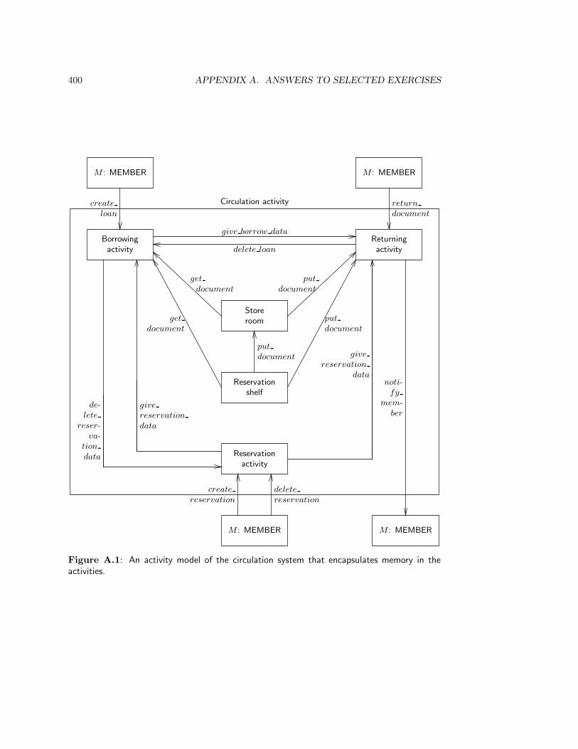
400 APPENDIX A. ANSWERS TO SELECTED EXERCISES
Borrowingactivity
Storeroom
Returningactivity
Reservationshelf
Reservationactivity
Circulation activity
M : MEMBER
create
loan
give borrow data
delete loan
get
document
get
document
put
document
put
document
put
document
give
reservation
data
de-lete
reser-va-
tion
data
give
reservation
data
M : MEMBER
return
document
M : MEMBER
noti-fy
mem-ber
M : MEMBER
create
reservation
delete
reservation
Figure A.1: An activity model of the circulation system that encapsulates memory in theactivities.
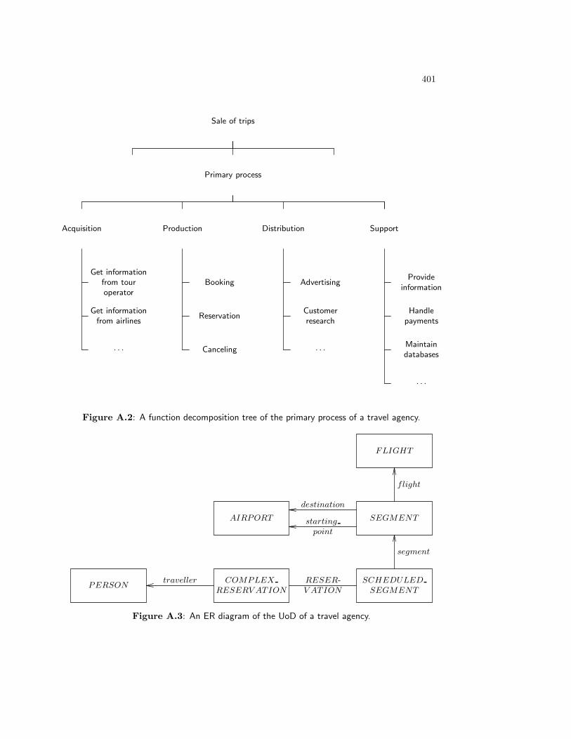
401
Sale of trips
Primary process
Acquisition Production Distribution Support
Get informationfrom touroperator
Get informationfrom airlines
· · ·
Booking
Reservation
Canceling
Advertising
Customerresearch
· · ·
Provideinformation
Handlepayments
Maintaindatabases
· · ·
Figure A.2: A function decomposition tree of the primary process of a travel agency.
SEGMENT
SCHEDULED
SEGMENT
COMPLEX
RESERV ATION
RESER-V ATION
PERSONtraveller
segment
FLIGHT
flight
AIRPORT
destination
starting
point
Figure A.3: An ER diagram of the UoD of a travel agency.
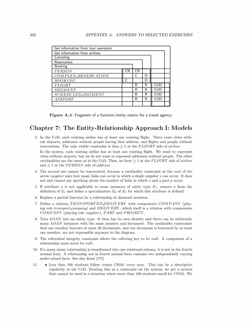
402 APPENDIX A. ANSWERS TO SELECTED EXERCISES
Get information from tour operators
Get information from airlinesCanceling
ReservationBooking
PERSON CR CR
COMPLEX RESERV ATION C D
BOOKING C D
FLIGHT R R CUD
SEGMENT R R CUD
SCHEDULED SEGMENT R R CUD
AIRPORT R R CUD· · · · · ·
Figure A.4: Fragment of a function/entity matrix for a travel agency.
Chapter 7: The Entity-Relationship Approach I: Models
2. In the UoD, each existing airline has at least one existing flight. There exist cities with-out airports, addresses without people having that address, and flights and people withoutreservations. The only visible constraint is thus ≥ 1 at the FLIGHT side of airline.
In the system, each existing airline has at least one existing flight. We want to representcities without airports, but we do not want to represent addresses without people. The othercardinalities are the same as in the UoD. Thus, we have ≥ 1 at the FLIGHT side of airline
and ≥ 1 at the PERSON side of address.
4. The second one cannot be represented, because a cardinality constraint at the root of thearrow supplier says how many links can occur in which a single supplier s can occur. It doesnot and cannot say anything about the number of links in which s and a part p occur.
5. If attribute a is not applicable to some instances of entity type E1, remove a from thedefinition of E1 and define a specialization E2 of E1 for which this attribute is defined.
6. Replace a partial function by a relationship in diamond notation.
7. Define a relation TRANSPORTED DELIV ERY with components COMPANY (play-ing role transport company) and DELIV ERY , which itself is a relation with componentsCOMPANY (playing role supplier), PART and PROJECT .
8. Turn LOAN into an entity type. It then has its own identity and there can be arbitrarilymany LOAN instances with the same member and document. The cardinality constraintsthat one member borrows at most 20 documents, and one document is borrowed by at mostone member, are not expressible anymore in the diagram.
9. The referential integrity constraint allows the referring key to be null. A component of arelationship must never be null.
10. If a many-many relationship is transformed into one relational schema, it is not in the fourthnormal form. A relationship not in fourth normal form contains two independently varyingmulti-valued facts. See also Kent [175].
11. • Less then 100 students follow course CS101 every year. This can be a descriptiveregularity in the UoD. Treating this as a constraint on the system, we get a systemthat cannot be used in a situation where more than 100 students enroll for CS101. We

403
should only turn this sentence into a system constraint if we can be absolutely surethat the UoD regularity expressed by the sentence will never be falsified.
• Course CS100 is a prerequisite for course CS101. This may or may not be an officialrule. If it is not an official rule, it is a descriptive sentence that expresses an observationmade of the UoD. If we were to turn this into a system constraint, we would turn thisobservation into a UoD regularity that will never be falsified; which is a risky decision.If the rule is a UoD constraint and we want to enforce this by means of the system,we should turn it into a system constraint. Exceptions cannot be recorded. If the rulechanges, we must then change the system specification.
• Students always follow CS100 before they follow CS101. This may be a consequenceof a rule or a consequence of a habit of the students; which habit may follow from thefact that CS100 really is a prerequisite of CS101, even if the rules don’t say so. Thesame considerations as above apply.
Chapter 8: The Entity-Relationship Approach II: Meth-ods
1. The first one can be represented by adding the cardinality ≥ 1 at the root of the arrowSALE → CLIENT . The other constraint says that the multivalued function CLIENT ×SHOP →→ PRODUCT defined by SALE assigns at most two products to any particular〈c, s〉 and this cannot be represented in the diagram.
4. • This is a car: Instance-type relationship.
• A Ford is a car: is a relationship.
• A Ford is a type of car: Instance-type relationship, since “Ford” is now treated as thename of an individual.
• A teacher is a member of staff: is a relationship.
5. Add relationships RECEIV E MARK FOR TEST and FINISH TEST that representthe events of obtaining a result. The relationships PRACTICAL REG and TEST REG
represent the events of registering for a practical and a test, respectively, and allocation of aresult attribute to these events is a type error.
7. The key of the relational schema corresponding to a relationship can now have componentsthat are themselves compound, and referential keys may now also be compound.
Chapter 9: Structured Analysis I: Models
3. (a) Material stores have only two operations: remove and add. Removal is a destructiveread and corresponds to the effect of a read and delete operation on a data store.Addition corresponds to a creation operation on a data store. Data stores have non-destructive reads and additionally have an update operation, which is absent frommaterial stores. Material flows move material items just like data flows move dataitems. However, if masses are manipulated (like water), then the flow is continuousand we need an additional notation to distinguish these from discrete flows. Materialmanipulations are physical processes that must be specified by means of notations fromphysics, chemistry, biology, etc. They can be discrete or continuous.
(b) There is no difference with material manipulation. The dashed line is therefore super-fluous and can be replaced by whatever notation is used for material flows.
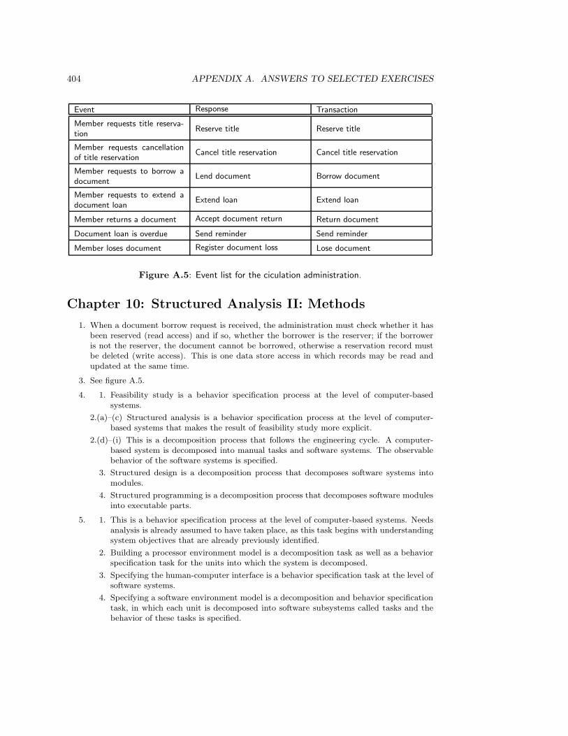
404 APPENDIX A. ANSWERS TO SELECTED EXERCISES
Event Response Transaction
Member requests title reserva-tion
Reserve title Reserve title
Member requests cancellationof title reservation
Cancel title reservation Cancel title reservation
Member requests to borrow adocument
Lend document Borrow document
Member requests to extend adocument loan
Extend loan Extend loan
Member returns a document Accept document return Return document
Document loan is overdue Send reminder Send reminder
Member loses document Register document loss Lose document
Figure A.5: Event list for the ciculation administration.
Chapter 10: Structured Analysis II: Methods
1. When a document borrow request is received, the administration must check whether it hasbeen reserved (read access) and if so, whether the borrower is the reserver; if the borroweris not the reserver, the document cannot be borrowed, otherwise a reservation record mustbe deleted (write access). This is one data store access in which records may be read andupdated at the same time.
3. See figure A.5.
4. 1. Feasibility study is a behavior specification process at the level of computer-basedsystems.
2.(a)–(c) Structured analysis is a behavior specification process at the level of computer-based systems that makes the result of feasibility study more explicit.
2.(d)–(i) This is a decomposition process that follows the engineering cycle. A computer-based system is decomposed into manual tasks and software systems. The observablebehavior of the software systems is specified.
3. Structured design is a decomposition process that decomposes software systems intomodules.
4. Structured programming is a decomposition process that decomposes software modulesinto executable parts.
5. 1. This is a behavior specification process at the level of computer-based systems. Needsanalysis is already assumed to have taken place, as this task begins with understandingsystem objectives that are already previously identified.
2. Building a processor environment model is a decomposition task as well as a behaviorspecification task for the units into which the system is decomposed.
3. Specifying the human-computer interface is a behavior specification task at the level ofsoftware systems.
4. Specifying a software environment model is a decomposition and behavior specificationtask, in which each unit is decomposed into software subsystems called tasks and thebehavior of these tasks is specified.

405
REGISTER
TEST
PRECONDITIONS
remove request
from D1
REALIZE
POSTCONDITIONS
get sv(SV1) get sv(SV2)PRECONDITIONS
SATISFIED
preconditions
not satisfied
send registration
to D2
Figure A.6: Outline of a PSD for the REGISTER function.
5. Structured design is a decomposition of tasks into units of code.
Modern structured development decomposes software systems into tasks, and tasks intomodules, where classical structured development decomposes software systems into softwaremodules immediately.
Chapter 11: Jackson System Development I: Models
1. Input: A registration request of student s for test t.Precondition: s and t exist and the register action can occur in the life of t.Postcondition: The registration request has been removed from D1 and a registration recordhas been sent to D3.
Precondition: s or t do not exist or the register action can occur in the life of t.Postcondition: The registration request has been removed from D1 and a refusal has beensent to D2.
Figure A.6 gives an outline of the REGISTER PSD.
2. The REPORT subtree of the LATE PSD is a short-running version of LATE. The con-nection cardinality must be changed so that the ≥ 0 cardinality is on the LATE side.
To turn ACCT HISTORY into a long-running function, make the short-running functionone iteration in a process that is triggered by the arrival of a historical query. The con-nection cardinality changes so that one ACCT HISTORY instance is connected to manyACCOUNT instances.
3. This requires addition of a JSD entity REGISTRATION . In ER terms, this is a relationshipbetween the ER entity type STUDENT and the ER entity type TEST . The register
action is the creation action for this relationship. The REGISTER function of figure 11.21is a function process that performs the input transactions in which this creation action isexecuted. The PSD of REGISTRATION is trivial and consists of a sequence register;

406 APPENDIX A. ANSWERS TO SELECTED EXERCISES
perform; mark. We should add the perform action to the TEST life cycle as well. TheREGISTRATION life cycle then shares all its actions with the TEST life cycle but enforcesan ordering per test–student pair.
4. What is required is that allocation must be a synchronous communication between ROOM
and ALLOCATE instances. Turn the data stream D2 into a controlled data stream thatlocks a ROOM instance, observes the state of the instance, and then updates the ROOM
instance.
Chapter 12: Jackson System Development II: Methods
1. This requires a periodic function process that scans all outstanding reservation processes andcancels those that are past their final date. The connection with the reservation processesmust be by controlled data stream, because the deletion is conditional upon the state of thedeleted processes.
2. The structure of D RESERV ATION is the same as that for T RESERV ATION . Thereare now two res borrow actions, t res borrow and d res borrow, and the normal borrow
action has an extended precondition that tests that none of these other cases is true.
3. The FINE life cycle now starts with a lose action and continues with an iteration over lose
and pay actions. A fine is only created upon the first document loss.
4. This is a historical query that is periodically triggered by a temporal event. It is therefore along-running function. Because it is a historical query, we cannot scan model processes ontheir current state using a state vector connection, but we must keep a log of the relevantaction occurrences in a data stream. In addition, the function process will take input fromthe clock, to be able to notice the end of a week. The system network and a possible processstructure for the periodic borrowing report function are shown in figure A.7. This processassumes that there is always at least one borrowing in a week. If this assumption cannotbe made, a provision for a null report must be added, similar to the null action of F1. TheLOAN process must be extended with the action add borrow to borrow stream immediatelyafter the borrow( and borrow res actions (figure 12.7).
Chapter 13: A Framework for Requirements EngineeringI: Models
1. (a) There is not enough information to put any other constraint in the model than n ≥ 0.
(b) A possible subject area PRODUCT OBJECTIV E is the tree whose root is GOAL.The rest is then part of the subject area PRODUCT ENV IRONMENT .
2. Figure A.8 gives a possible trace of a model containing one student s, one course c and onetest t. Each column shows a history of an object, with the earliest action occurrences atthe top. Synchronization by common actions is indicated by horizontal lines. Actions inthe history of different objects not connected by a horizontal line may occur in any order(compatible with the synchronization points). The student receives a mark twice, withoutdoing a test in between. This possibility remains when there are many students, many coursesand many tests.
4. (a) Figure A.9 shows part of a specification of a simulation of a data stream. The connectedprocesses are represented by external entities. The data store contains records labeledby a sequence number, that indicates the sequence in which they were put in. It
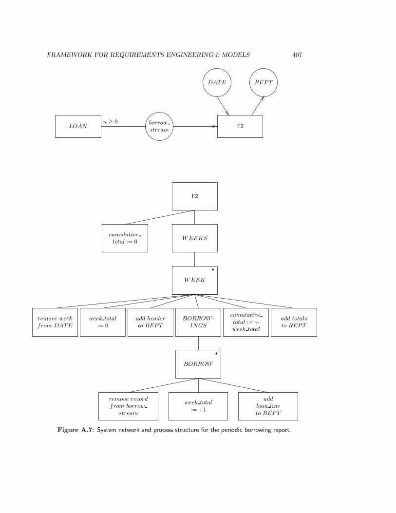
FRAMEWORK FOR REQUIREMENTS ENGINEERING I: MODELS 407
F2
cumulative
total := 0WEEKS
WEEK
*
remove week
from DATE
week total
:= 0add header
to REPT
BORROW -INGS
cumulative
total := +week total
add totals
to REPT
BORROW
*
remove record
from borrow
stream
week total
:= +1
add
loan line
to REPT
LOAN F2borrow
stream
n ≥ 0
REPTDATE
Figure A.7: System network and process structure for the periodic borrowing report.
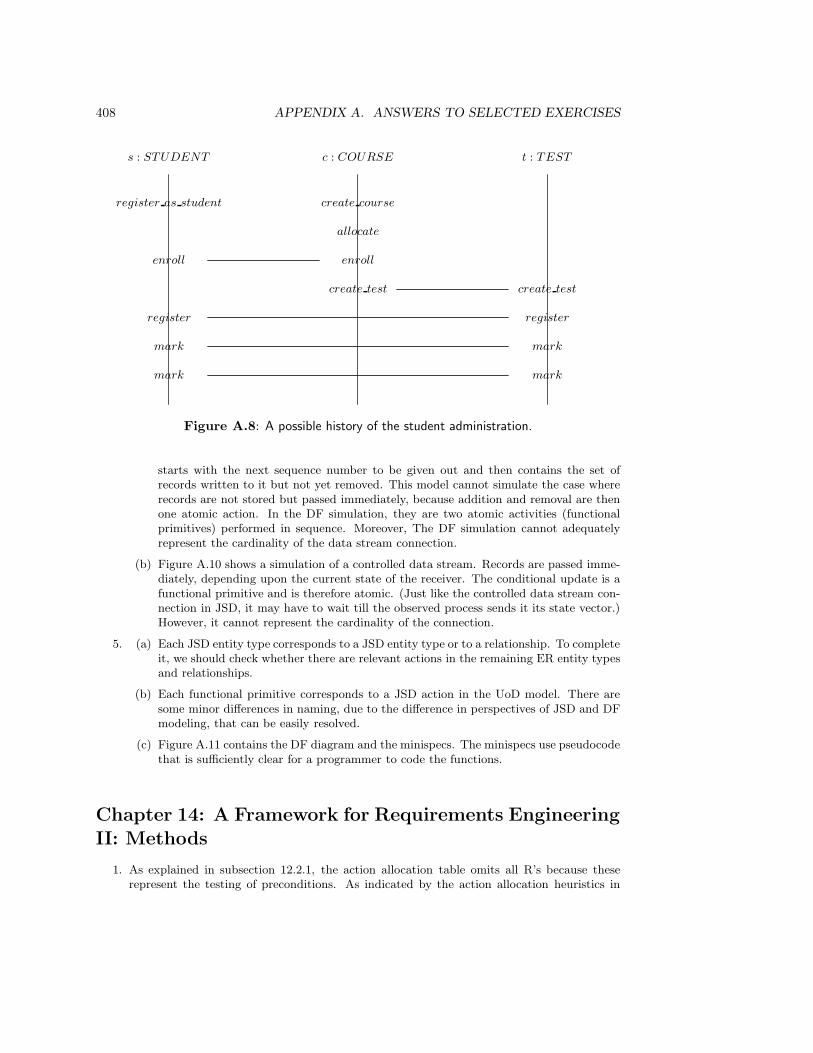
408 APPENDIX A. ANSWERS TO SELECTED EXERCISES
s : STUDENT c : COURSE t : TEST
register as student create course
allocate
enroll enroll
create test create test
register register
mark mark
mark mark
Figure A.8: A possible history of the student administration.
starts with the next sequence number to be given out and then contains the set ofrecords written to it but not yet removed. This model cannot simulate the case whererecords are not stored but passed immediately, because addition and removal are thenone atomic action. In the DF simulation, they are two atomic activities (functionalprimitives) performed in sequence. Moreover, The DF simulation cannot adequatelyrepresent the cardinality of the data stream connection.
(b) Figure A.10 shows a simulation of a controlled data stream. Records are passed imme-diately, depending upon the current state of the receiver. The conditional update is afunctional primitive and is therefore atomic. (Just like the controlled data stream con-nection in JSD, it may have to wait till the observed process sends it its state vector.)However, it cannot represent the cardinality of the connection.
5. (a) Each JSD entity type corresponds to a JSD entity type or to a relationship. To completeit, we should check whether there are relevant actions in the remaining ER entity typesand relationships.
(b) Each functional primitive corresponds to a JSD action in the UoD model. There aresome minor differences in naming, due to the difference in perspectives of JSD and DFmodeling, that can be easily resolved.
(c) Figure A.11 contains the DF diagram and the minispecs. The minispecs use pseudocodethat is sufficiently clear for a programmer to code the functions.
Chapter 14: A Framework for Requirements EngineeringII: Methods
1. As explained in subsection 12.2.1, the action allocation table omits all R’s because theserepresent the testing of preconditions. As indicated by the action allocation heuristics in
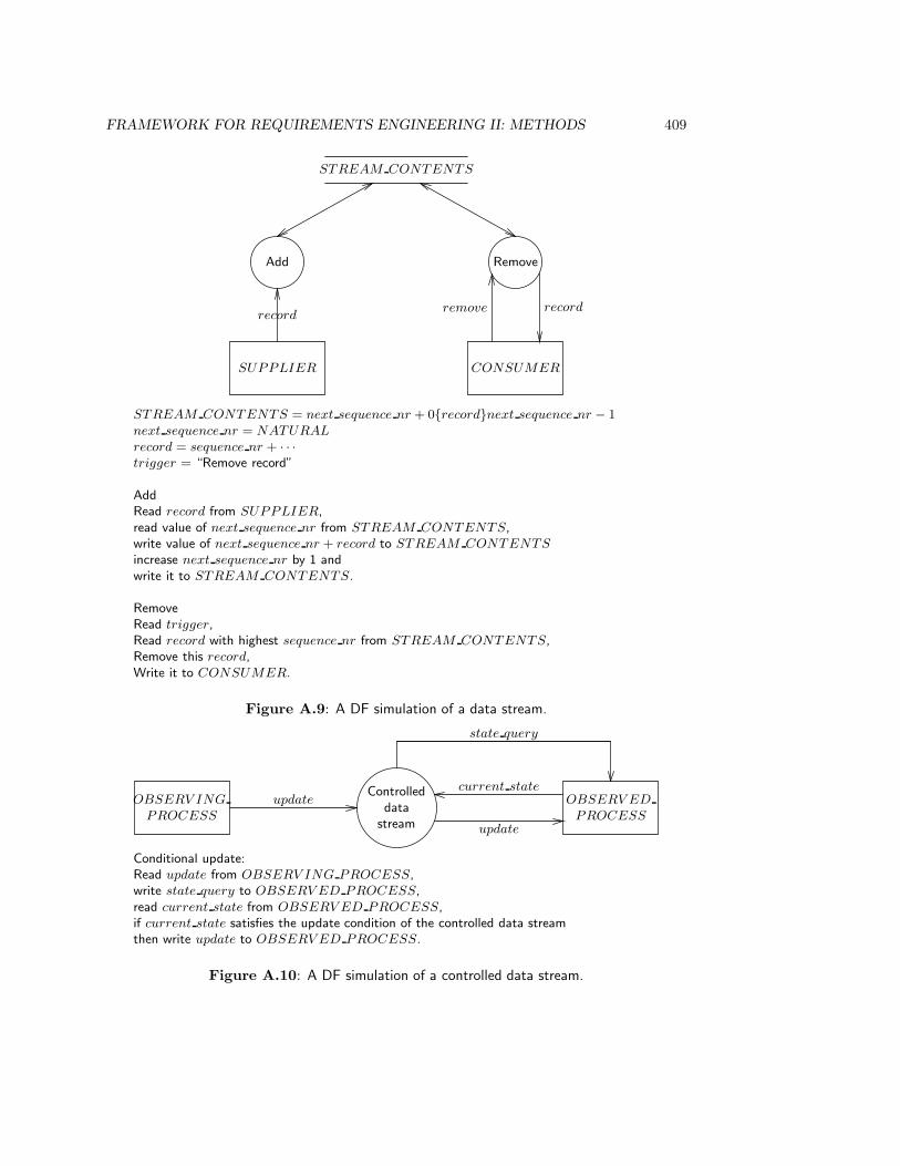
FRAMEWORK FOR REQUIREMENTS ENGINEERING II: METHODS 409
STREAM CONTENTS
Add
SUPPLIER
Remove
CONSUMER
recordrecordremove
STREAM CONTENTS = next sequence nr + 0{record}next sequence nr − 1next sequence nr = NATURAL
record = sequence nr + · · ·trigger = “Remove record”
AddRead record from SUPPLIER,read value of next sequence nr from STREAM CONTENTS,write value of next sequence nr + record to STREAM CONTENTS
increase next sequence nr by 1 andwrite it to STREAM CONTENTS.
RemoveRead trigger,Read record with highest sequence nr from STREAM CONTENTS,Remove this record,Write it to CONSUMER.
Figure A.9: A DF simulation of a data stream.
OBSERV ING
PROCESS
Controlleddata
stream
OBSERV ED
PROCESS
updatecurrent state
update
state query
Conditional update:Read update from OBSERV ING PROCESS,write state query to OBSERV ED PROCESS,read current state from OBSERV ED PROCESS,if current state satisfies the update condition of the controlled data streamthen write update to OBSERV ED PROCESS.
Figure A.10: A DF simulation of a controlled data stream.
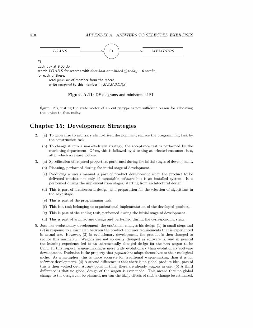
410 APPENDIX A. ANSWERS TO SELECTED EXERCISES
LOANS F1 MEMBERS
F1:Each day at 9:00 do:search LOANS for records with date last reminded ≤ today − 6 weeks,for each of these,
read pass nr of member from the record,write suspend to this member in MEMBERS.
Figure A.11: DF diagrams and minispecs of F1.
figure 12.3, testing the state vector of an entity type is not sufficient reason for allocatingthe action to that entity.
Chapter 15: Development Strategies
2. (a) To generalize to arbitrary client-driven development, replace the programming task bythe construction task.
(b) To change it into a market-driven strategy, the acceptance test is performed by themarketing department. Often, this is followed by β testing at selected customer sites,after which a release follows.
3. (a) Specification of required properties, performed during the initial stages of development.
(b) Planning, performed during the initial stage of development.
(c) Producing a user’s manual is part of product development when the product to bedelivered consists not only of executable software but is an installed system. It isperformed during the implementation stages, starting from architectural design.
(d) This is part of architectural design, as a preparation for the selection of algorithms inthe next stage.
(e) This is part of the programming task.
(f) This is a task belonging to organizational implementation of the developed product.
(g) This is part of the coding task, performed during the initial stage of development.
(h) This is part of architecture design and performed during the corresponding stage.
5. Just like evolutionary development, the craftsman changes his design (1) in small steps and(2) in response to a mismatch between the product and user requirements that is experiencedin actual use. However, (3) in evolutionary development, the product is then changed toreduce this mismatch. Wagons are not so easily changed as software is, and in generalthe learning experience led to an incrementally changed design for the next wagon to bebuilt. In this respect, wagon-making is more truly evolutionary than evolutionary softwaredevelopment. Evolution is the property that populations adapt themselves to their ecologicalniche. As a metaphor, this is more accurate for traditional wagon-making than it is forsoftware development. (4) A second difference is that there is no global product idea, part ofthis is then worked out. At any point in time, there are already wagons in use. (5) A thirddifference is that no global design of the wagon is ever made. This means that no globalchange to the design can be planned, nor can the likely effects of such a change be estimated.
FRAMEWORK FOR REQUIREMENTS ENGINEERING II: METHODS 411
Changes must be local and only incrementally different from designs that are known to workfrom experience.
The difference with experimental development is (6) that the customer requires a robustproduct. The livelihood of the customer depends in part on the quality of the product, sothe customer doesn’t want any surprises. This is another explanation for the incrementalnature of design changes.
6. (a) ETHICS only contains product development tasks.
(b) The entire ETHICS method deals with the social system level. The two questions thatit tries to answer are: 1. How can the efficiency and job satisfaction needs of theorganization unit be met? and 2. How do we decompose the organization unit intosocial and technical subsystems so that these needs are met?
(c) ETHICS contains an exact match with the engineering cycle: tasks 1 to 9 correspondto needs analysis. Tasks 10 and 11 correspond to synthesis, simulation and eval-uation. Task 12 corresponds to choice. This ends the correspondence with the engi-neering cycle. In terms of our development framework, task 13 is a decomposition taskthat brings us to a lower level of aggregation.
Task 14 implements the design and task 15 evaluates the implementation. Thus, tasks13, 14 and 15 correspond to the regulatory cycle.
7. (a) All tasks that say which documents must be written and whom to consult at whichpoint in time are process management tasks. In particular, the assemble report tasksare process management tasks.
(b) Social system level: feasibility study and requirements analysis. Software systemlevel: requirements specification. Decomposition of software system: investigatetechnical system options (410, 420). Software subsystem level: specify logical de-sign. Software subsystem decomposition: physical design.
(c) Feasibility study and requirements analysis are two iterations through the engineeringcycle at the social system level. After the preliminary cycle (feasibility study), require-ments analysis performs a thorough needs analysis (investigate current environment),generates solutions, simulates and evaluates these (cost/benefit analysis and impactanalysis in task 210) and chooses one.
Requirements specification does not match to the engineering cycle. It can be viewedas a conceptual modeling task, in which a vaguely specified solution is modeled moreexplicitly. This is a descriptive activity; the normative questions have been dealt within requirements analysis (task 2).
Task 4 (investigate technical system options) is a decomposition that follows the rationalproblem solving cycle.
Task 5 (specify logical design) is a conceptual modeling task at the level of softwaresubsystems.
Chapter 16: Selecting a Development Strategy
5. (a) Spiral method. The growth envelope is limited, understanding of the requirements ishigh and robustness of the system must be very high. Depending upon available prod-uct alternatives, transformational development or waterfall development are possibleoptions.
Euromethod. Although this is an embedded system and not an information system,it is nevertheless illuminating to apply the Euromethod heuristics. The initial state
412 APPENDIX A. ANSWERS TO SELECTED EXERCISES
is that there exist requirements for the current generation of control systems. Theseare well-understood and the project aims at reimplementing these systems using newtechnology. According to figure 16.6, this should be performed in several adaptations.Due to the high safety requirements and the strategic importance of of the system,risk must be reduced to a minimum. It is decided to perform two adaptations, onein which a global system design is produced and a second one in which this design isimplemented.
In both adaptations, the complexity of the manipulated information is low; however,the target domain factor more suitable to this domain is the complexity of the controlstructure of the system, and this is complex. Furthermore, the strategic importanceof the system is high, which increases the uncertainty about the system. Complexityand uncertainty are further increased because the complexity of the target technologyis high and the technology is novel. Uncertainty arises in the project domain as well,because the development technology is complex and relatively unknown: the company’sengineers have little experience with computer technology. All of this leads to theselection of an incremental construction strategy: Requirements are known but will beimplemented incrementally for each of the two adaptation processes. Note that thesecond adaptation process (from global design to implementation) can start as soon asthe first process delivered its first increment of the global design and that from thatpoint onwards, there will be two parallel adaptation processes until the global designis finished.
In this example, Euromethod leads to a more conservative advise than the spiralmethod. This is mainly due to the larger number of factors considered by Euromethod,which leads to a sharper focus on the project risks and thus to more risk-avoidance.
(b) Spiral method. The growth envelope is large and the understanding of requirements islow. Robustness of the system must be high and there is, at the higher levels of net-work technology, no technology of reusable components. (At the lower levels, standardnetwork software is available on the market.) Architecture understanding is low. Thespiral method heuristics lead to risk reduction followed by waterfall as one possiblestrategy, and the full spiral method as another. Due to the high robustness desired ofthe system, risk reduction followed by waterfall is chosen.
Euromethod The difference between initial and final state leads to a decision to performmore than one adaptation. One possible sequence would be the production of aninformation system change study first, the production of a global design next, theproduction of a tested system next, and finally the production of an installed system.For any of these adaptations, the information system complexity factors all score on thehigh side; the information system uncertainty factors all score on the uncertain side.Due to the many different systems in operation, the complexity of the computer systemis high. The uncertainty about the computer system is medium to low, for all computertechnology to be used in the project is commercially available. The complexity of theproject task is high and the uncertainty of the project is medium to high. The numberof interfaces is potentially high. Project uncertainty is also increased by the potentialdependency on subcontractors and on other IS adaptations. Given the complexity anduncertainty about the target domain as well as about the project, the project managerwould do well to keep the complexity and novelty of the development technology low. Inthe face of all of this uncertainty, the Euromethod heuristics recommend evolutionaryconstruction.
The difference with the spiral method recommendation can be explained by the factthat risk reduction, recommended by the spiral method, is always recommended byEuromethod (we did not treat risk reduction in chapter 16). Furthermore, the sequential

FRAMEWORK FOR REQUIREMENTS ENGINEERING II: METHODS 413
nature of the waterfall process is also present in the Euromethod advice to performseveral adaptations in sequence. The Euromethod advice can be viewed as a refinementof the spiral method advice by recommending evolutionary construction.

Appendix B
Cases
B.1 The Teaching Administration
A teaching administration maintains data about courses, practicals, tests, examinations andstudents. Each course and each practical is given regularly and there are one or more testsfor each course. An examination consists of a number of tests. The examination is done bydoing these tests. Examinations are done once every month and consist of a ceremony inwhich students receive proof of having passed the examination. When a student hands overproof of having done these tests with sufficient result, he or she has the right to participatein the ceremony.
To be able to do a test for a course, a student must register for the test. Each testhas two or more supervisors, who check that the test participants are registered for thetest. Students must register for a test at the teaching administration. One day before thetest is conducted, the teaching administration produces a list of test participants, and thisis given to the supervisors. When students come to a test unregistered, they are sent bythe test supervisor to the teaching administration to register. The student receives a lateregistration slip from the administration, which he or she can show to the supervisor asproof of registration.
There are members of staff, called counselors, whose task it is to monitor student progressand help students when there are problems with their progress. Every six months, the resultsof all students are aggregated in a report and discussed by student counselors. Studentswhose progress is too slow, are called to their counselor for advice. In addition, each studentreceives an advise about study continuation after his or her first year of study. Every year,each student receives a report about his or her results so far.
B.2 The University Library
The functions of the Free University Library are (1) to acquire documents containing infor-mation that is of use for scientific research and education, (2) to catalog these documents,(3) make them available, (4) preserve them, and (5) to act as custodian of the documentsit acquired. The collection is made available not only for the Free University but for anyscientific research or education at all. Other universities and colleges have the right to use
415
416 APPENDIX B. CASES
the library, and as a matter of fact do so. The only prerequisite for getting registered as alibrary user is showing a valid proof of identity, so private individuals can use the libraryas well. However, most users are students or staff at the Free University.
The library is divided into departments that more or less reflect the structure of theuniversity in departments. Thus, there is the Biology library for the faculty of Biology, theMathematics and Computer Science library for the Faculty of Mathematics and ComputerScience, etc. Department libraries are located close to the Faculty they serve. Departmentlibraries are grouped together into Scientific Area libraries. For example, there are α, β andγ areas. Libraries in one scientific area have a common administration.
A user is someone who has a reader’s pass. Any student or employee can acquire a pass,as well as citizens who are not otherwise related to the university. A group of employeescan also acquire a pass, called a “group pass”. There should be one person accountable forthe actions of this group, but any member of the group can borrow a book.
The library acquires a wide diversity of items, such as books, journals, series (e.g. theSpringer Lecture Notes in Computer Science), Proceedings, internal reports from their ownor from other universities, unpublished reports from research laboratories, Ph.D. theses,maps, microfiches, videotapes, old manuscripts, newspapers, microfilms, etc. Some of theseare acquired for students (often several copies), most of these are for research purposes.Books themselves can come into a great variety of forms, such as multivolume works, multi-edition works, and even works that appear as one volume in one edition and as severalvolumes in the next — after which only volume 1 goes through successive editions.
Most books can be lent to users, but some can only be read in special rooms. Similarly,old volumes of journals, when bound, can be borrowed, but loose issues cannot be borrowed.Borrowable items receive a unique code so that they can be traced to a borrower.
A user can borrow a book for three weeks. Researchers can in addition borrow it forthree months. At the end of the allowed lending period, a user should return the book orelse renew the borrowing. Renewal can only be done when there is no reservation for thebook. If a user does not return of book or does not renew the lending period, action is onlytaken after 1 extra week, by sending him or her (or them) a reminder. So a user is remindedof his obligation to return the book 4 weeks after it was borrowed. If it is not yet returnedor renewed, a second reminder is sent after 7 weeks. After the second reminder, the userhas still one week to respond. If one week after the second reminder there is no messagefrom the user, he or she must pay a fine of Dfl 70 and is not allowed to borrow any morebooks until the book is returned and the fine is paid.
Any user can reserve books that are currently borrowed by someone else. He or she willreceive a message when the book is available and the library will hold the book for ten daysso that this user can borrow the book. If the book is not fetched after ten days, the bookis returned to the shelf. There can be at most one reserver for a book.
If a user loses a book, he or she has to report this to the administration, who will issuean invoice for the price of the book. If a user loses a pass, the pass is registered as lost andthe library will issue a new pass at no cost. If the lost pass is found, the user has to returnit to the library. Journal issues can be lost as well. Since issues are not lent to users, thiscannot be attributed to any particular reader.
For some years now, the library experiences problems that cause increasing hindranceto library staff as well as users and that hinder the library in the realization of its primaryfunction, making scientific documents available to its users. An unknown number of booksand journal issues is lost or stolen, and often it is not known which of the two is the case.
B.2. THE UNIVERSITY LIBRARY 417
Sometimes, a book registered as present cannot be found on its shelf and there is no recordof it being borrowed to anyone. On the other hand, a book registered as borrowed or even asstolen may be found on a shelf. There are no reliable statistics of the use of documents andof their availability, such as the ratio between reservations and borrowings. Availability ofdocuments is further decreased because some users, especially University staff, lend booksfor months or even years without bothering to return them.
These problems have budgetary consequences, for lost or stolen documents must be re-placed and the costs of this are added to the normal costs of paying for journal subscriptionsand the acquisition of books. In the coming years, the library budget for the university isnot likely to increase, to put it mildly. In view of cuts in university funding by the govern-ment, the budget will probably decrease in the next few years. At the same time, scientificpublishers start new journals almost every month, and tend to double the subscription rateevery few years. Most subscriptions are in US dollars, and due to fluctuations in the dollarrate, this price increase may pass unnoticed in some years and hit extra hard in other years.
Some faculties chronically overspend their budget by simply refusing to terminate sub-scriptions. Especially faculties of “old” sciences such as Chemistry, Physics and Mathe-matics have some very expensive reference journals and in addition a wide assortment ofsubscriptions that cover some specialities within their science very well. However, those fac-ulties argue that they have a minimal subscription portfolio already, and that terminationof more subscriptions would endanger the quality of their scientific research, which is of ahigh level. All faculties, young and old, argue that they only have subscriptions to a fractionof the available journals, and that it would be irresponsible to terminate even one of them.For some of the older faculties, some of these subscriptions were started in the nineteenthcentury and the library and faculties all agree that it would be a shame to terminate sucha subscription. However, they disagree on whether this implies that these subscriptionstherefore should not be terminated, no matter what the budgetary consequences.
There are no competitors which aim at the same part of the market, and the libraryis a non-profit organization, so performance cannot be measured in terms of profit. Thelong-term objective of the library is to improve the level of service currently provided tothe user, and to look for possibilities to provide new services. As part of the realization ofthe first objective, organizational measures are taken that aim at making more efficient useof the financial means at the disposal of the library than is done now. These measures aredescribed below.
As part of the realization of the second objective, the possibilities for providing newservices are being studied. There is a national EDI network for university libraries andpublic libraries of which the library is not yet a part. Access to this network would allowthe users to find literature fast and request it from the appropriate library anywhere in TheNetherlands. Possibilities for extending this kind of service by connecting to a Europeannetwork are also considered. In addition, the library catalogue should be made available on-line to users, and there are plans to provide entry into the catalogue by terminals installedat the library itself, through a modem connection, and through the local area network ofthe university.
To eliminate some problems experienced by the library, and reduce others, the libraryis reorganized. To spend the library budget more efficiently, all double subscriptions tojournals should be terminated, so that for each journal, there is at most one subscriptionowned by the University. Similarly, books already present in the University library in onedepartment should not be bought by another, unless there is good reason to do so.

418 APPENDIX B. CASES
Journals cannot be borrowed anymore, neither in single issues nor in bound volumes. Alllibrary departments get photocopiers so that papers from journals can be copied withoutborrowing them.
To reduce theft, documents that can be borrowed are marked in an indelible way, andports with sensors are installed at the entry of each library.
An IS should be installed that supports library staff in the stricter enforcement of libraryrules. For example, the borrowing limit of three weeks will be strictly maintained, and tosupport this enforcement, a report should be produced each week on documents who areborrowed for longer than their allowed lending period, together with a standard letter thatis sent to the user. In addition, once every year, all users are to be sent a list of lost orstolen books, so that they become aware of the problem.
Appendix C
An outline of some developmentmethods
C.1 ETHICS
ETHICS (Effective Technical and Human Implementation of Computer-Based Systems) is asociotechnical system development method, developed by Enid Mumford of the ManchesterBusiness School in the late 1970s and early 1980s [237, 235]. A sociotechnical develop-ment method is a method to develop a system that consists of of a human subsystem anda technical subsystem. Sociotechnical development is oriented to developing both subsys-tems in an integrated way, so that the integrated system functions in an optimal way. Thisdevelopment strategy has its background in studies done in the 1950s on the relationshipbetween social structure and technology in organizations [347]. Emery and Trist [95] givea brief introduction to sociotechnical development. Bostrom and Heinen [47] give an intro-duction to sociotechnical ideas for system developers and apply these ideas to an analysis ofsuccess and failure factors of information system development. ETHICS is a sociotechnicaldevelopment method oriented towards information systems at the operational level of anorganization. Pava [256] shows how sociotechnical ideas can be applied to the developmentof strategic information systems.
ETHICS can best be viewed as a development method for organization units, withequal emphasis on the job satisfaction aspect, the workflow aspect and the informationaspect of the unit. Most of the method is spent in requirements determination, whichfollows a rational choice cycle. Work design and implementation involves designing andimplementing a (new or renovated) information system, but there is no specific advice ofETHICS about this.
ETHICS is a participative method that follows the consensus model. The efficiencyneeds and job satisfaction needs are collected and diagnosed by means of questionnairesgiven to all people who work in the organization unit. Decisions are made by involving allworkers in the unit, who should all support the decisions. The decision about the changeoption should be verified with the appropriate management authorities.
An outline of the ETHICS method is given in figure C.1.
419

420 APPENDIX C. AN OUTLINE OF SOME DEVELOPMENT METHODS
1. Determine the reasons for change.
2. Determine the boundaries of the organization unit to be developed.
3. Describe the organization unit as it currently is.
4. Define the key objectives of the unit.
5. Define the key tasks performed in the unit.
6. Determine the information needs of these tasks.
7. Collect the accidental problems with the current organization of work in the unit, i.e.problems that are due to the way the workflow in the unit is currently implemented.Diagnose these problems. The underlying problems are called efficiency needs.
8. Collect information on job satisfaction problems in the current organization of work.Diagnose these, and call the underlying problems job satisfaction needs.
9. Use the information needs, efficiency needs and job satisfaction needs to determine thechange objectives of the development process.
10. Generate and evaluate organizational change options.
11. Generate and evaluate technical change options.
12. Merge the technical and organizational options and choose one.
13. Make a detailed work design for the chosen option.
14. Implement the work design.
15. Evaluate the new situation.
Figure C.1: Outline of the ETHICS method.
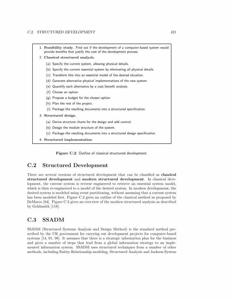
C.2. STRUCTURED DEVELOPMENT 421
1. Feasibility study. Find out if the development of a computer-based system wouldprovide benefits that justify the cost of the development process.
2. Classical structured analysis.
(a) Specify the current system, allowing physical details.
(b) Specify the current essential system by eliminating all physical details.
(c) Transform this into an essential model of the desired situation.
(d) Generate alternative physical implementations of the new system.
(e) Quantify each alternative by a cost/benefit analysis.
(f) Choose an option.
(g) Propose a budget for the chosen option.
(h) Plan the rest of the project.
(i) Package the resulting documents into a structured specification.
3. Structured design.
(a) Derive structure charts for the design and add control.
(b) Design the module structure of the system.
(c) Package the resulting documents into a structured design specification.
4. Structured implementation.
Figure C.2: Outline of classical structured development.
C.2 Structured Development
There are several versions of structured development that can be classified as classicalstructured development and modern structured development. In classical deve-lopment, the current system is reverse engineered to retrieve an essential system model,which is then re-engineered to a model of the desired system. In modern developmemt, thedesired system is modeled using event partitioning, without assuming that a current systemhas been modeled first. Figure C.2 gives an outline of the classical method as proposed byDeMarco [84]. Figure C.3 gives an overview of the modern structured analysis as describedby Goldsmith [118].
C.3 SSADM
SSADM (Structured Systems Analysis and Design Method) is the standard method pre-scribed by the UK government for carrying out development projects for computer-basedsystems [14, 91, 98]. It assumes that there is a strategic information plan for the businessand gives a number of steps that lead from a global information strategy to an imple-mented information system. SSADM uses structured techniques from a number of othermethods, including Entity-Relationship modeling, Structured Analysis and Jackson System
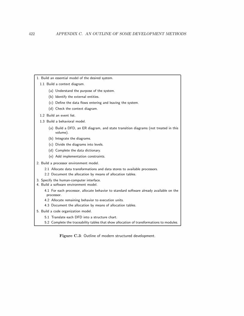
422 APPENDIX C. AN OUTLINE OF SOME DEVELOPMENT METHODS
1. Build an essential model of the desired system.
1.1 Build a context diagram.
(a) Understand the purpose of the system.
(b) Identify the external entities.
(c) Define the data flows entering and leaving the system.
(d) Check the context diagram.
1.2 Build an event list.
1.3 Build a behavioral model.
(a) Build a DFD, an ER diagram, and state transition diagrams (not treated in thisvolume).
(b) Integrate the diagrams.
(c) Divide the diagrams into levels.
(d) Complete the data dictionary.
(e) Add implementation constraints.
2. Build a processor environment model.
2.1 Allocate data transformations and data stores to available processors.
2.2 Document the allocation by means of allocation tables.
3. Specify the human-computer interface.4. Build a software environment model.
4.1 For each processor, allocate behavior to standard software already available on theprocessor.
4.2 Allocate remaining behavior to execution units.
4.3 Document the allocation by means of allocation tables.
5. Build a code organization model.
5.1 Translate each DFD into a structure chart.
5.2 Complete the traceability tables that show allocation of transformations to modules.
Figure C.3: Outline of modern structured development.

C.3. SSADM 423
Development. SSADM assumes that there is a project board which monitors the informa-tion strategy of the business and to which the project team executing the SSADM processreports. Every step in the feasibility study is verified with the project board.
SSADM consists of 5 tasks, called modules, each of which is divided into one or moretasks called stages, which themselves are devided into a sequence of steps. Figures C.4and C.5 give an outline of SSADM. The construction, test and operation tasks are not partof SSADM.

424 APPENDIX C. AN OUTLINE OF SOME DEVELOPMENT METHODS
Feasibility study
0. Feasibility
010 Prepare feasibility study. Define scope of the project, identify stakeholders andproblem areas, create a high level model of data and activities.
020 Define the problem. Identify the activities and information necessary for thebusiness unit to meet its objectives, identify those aspects of current operationswhere improvement is required, identify new features of the system, identifynonfunctional requirements.
030 Identify feasibility options. Draw up a list of minimum requirements, to be metby all options. make a list of up to six business system options and up to sixtechnical system options. Combine, trim down to about three, document theseand do a cost/benefit analysis and impact analysis of these. Identify preferredoption and assist project board and users in selection.
040 Assemble feasibility report.
Requirements analysis
1. Investigate current environment.
110 Establish analysis framework. Review output from feasibility study, identifytarget users, plan the project.
120 Investigate and define requirements. Investigate current system operation, in-cluding frequencies, volumes, etc. Identify intended users and identify opportu-nities for improving current system, as well as desired functions and data notcurrently provided.
130 Investigate current processing. Create a data flow diagram of current processing.Identify shortcomings of current processing with users and add to requirements.
140 Investigate current data. Create an entity model of current data. Identifyshortcomings of current data with users and add to requirements.
150 Derive logical view of current services. Make logical model of current processingand data.
160 Assemble investigation results.
2. Investigate business system options.
210 Define business system options. Make a list of requirements, define up to sixbusiness solutions, cut down to three with user, describe each of these and do acost/benefit analysis and an impact analysis.
220 Select business system option. Present to project board, record choice madeand complete description of this choice.
Figure C.4: Feasibility study and requirements analysis in SSADM.
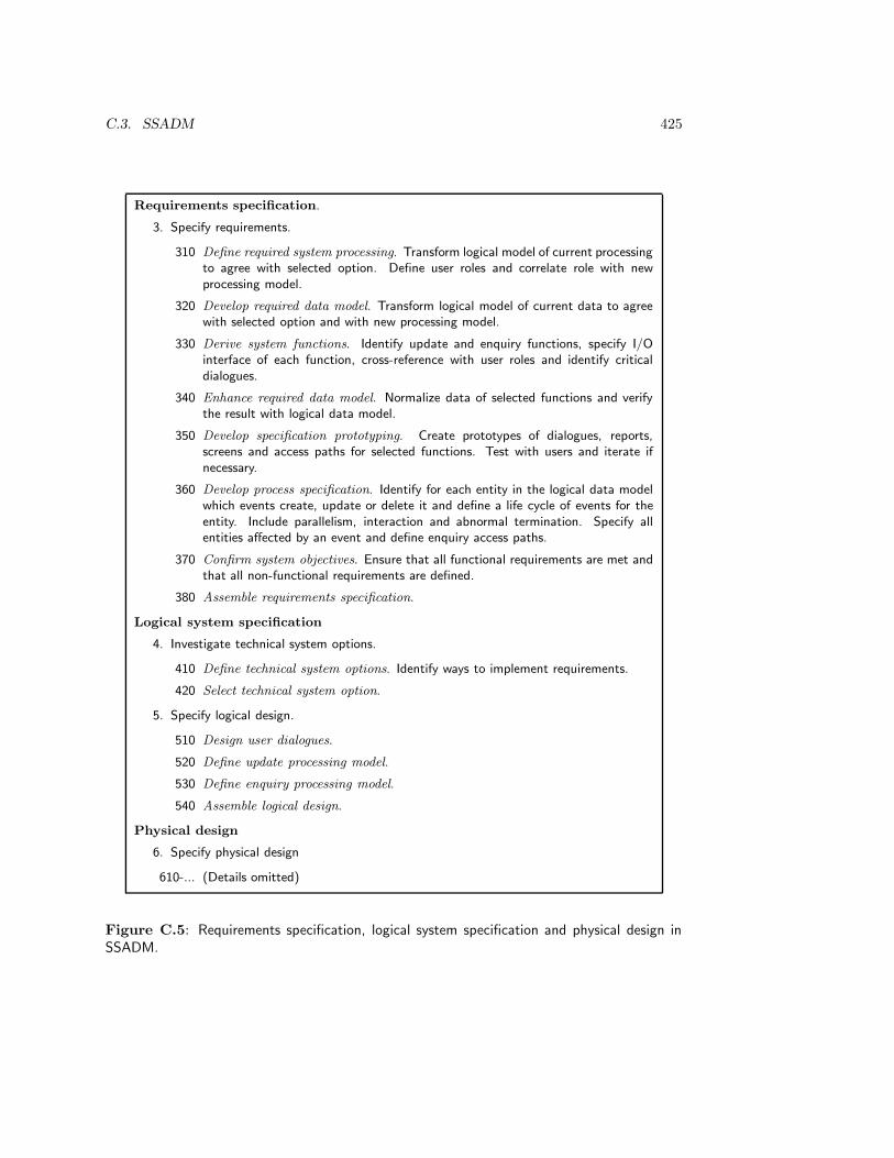
C.3. SSADM 425
Requirements specification.
3. Specify requirements.
310 Define required system processing. Transform logical model of current processingto agree with selected option. Define user roles and correlate role with newprocessing model.
320 Develop required data model. Transform logical model of current data to agreewith selected option and with new processing model.
330 Derive system functions. Identify update and enquiry functions, specify I/Ointerface of each function, cross-reference with user roles and identify criticaldialogues.
340 Enhance required data model. Normalize data of selected functions and verifythe result with logical data model.
350 Develop specification prototyping. Create prototypes of dialogues, reports,screens and access paths for selected functions. Test with users and iterate ifnecessary.
360 Develop process specification. Identify for each entity in the logical data modelwhich events create, update or delete it and define a life cycle of events for theentity. Include parallelism, interaction and abnormal termination. Specify allentities affected by an event and define enquiry access paths.
370 Confirm system objectives. Ensure that all functional requirements are met andthat all non-functional requirements are defined.
380 Assemble requirements specification.
Logical system specification
4. Investigate technical system options.
410 Define technical system options. Identify ways to implement requirements.
420 Select technical system option.
5. Specify logical design.
510 Design user dialogues.
520 Define update processing model.
530 Define enquiry processing model.
540 Assemble logical design.
Physical design
6. Specify physical design
610-... (Details omitted)
Figure C.5: Requirements specification, logical system specification and physical design inSSADM.


Bibliography
[1] R.J. Abbott. Program design by informal English descriptions. Communications of the ACM,26:882–894, 1983.
[2] ACM. ACM code of professional conduct. Communications of the ACM, 16:262–269, 1973.
[3] P.E. Agre. Book review of Lucy A. Suchman, Plans and Situated Actions: The Problem of
Human-Machine Communication. Artificial Intelligence, 43:369–384, 1990.
[4] W.W. Agresti. The conventional software life-cycle model: its evolution and assumptions.In W.W. Agresti, editor, New Paradigms for Software Development, pages 2–5. ComputerSociety Press, 1986.
[5] W.W. Agresti, editor. New Paradigms for Software Development. Computer Society Press,1986.
[6] B. Alabiso. Transformation of data flow analysis models to object oriented design. In N. Mey-rowitz, editor, Object-Oriented Programming Systems, Languages and Applications, Confer-
ence Proceedings, pages 335–353. ACM Press, 1988. SIGPLAN Notices, volume 23.
[7] M. Alavi. An assessment of the prototyping approach to information systems development.Communications of the ACM, 27:556–563, 1984.
[8] M. Alavi and J.C. Wetherbe. Mixing prototyping and data modeling for information systemdesign. IEEE Software, 11(5):86–91, May 1991.
[9] R.E. Anderson, D.G. Johnson, D. Gotterbarn, and J. Perrolle. Using the new ACM code ofethics in decision making. Communications of the ACM, 36(2):98–105, February 1993.
[10] S.J. Andriole. Fast, cheap requirements: prototype, or else! IEEE Software, 14(3):85–87,March 1994.
[11] L.B. Archer. Technological Innovation — A Methodology. Inforlink, on behalf of the SciencePolicy Foundation, 1971.
[12] L.B. Archer. Whatever became of design methodology? Design Studies, 1(1):17–18, July1971.
[13] L.B. Archer. Systematic method for designers. In N. Cross, editor, Developments in Design
Methodology, pages 57–82. Wiley, 1984. Originally published by The Design Council, 1965.
[14] C. Ashworth and M. Goodland. SSADM: A Practical Approach. McGraw-Hill, 1990.
[15] M. Asimov. Introduction to Design. Prentice-Hall, 1962.
[16] D.E. Avison and A.T. Wood-Harper. Multiview: An Exploration in Information Systems
Development. Blackwell, 1990.
[17] R.L. Baber. ”software engineering” vs. software engineering. Computer, 22(5):81, 1989.
[18] J.C.M. Baeten and W.P. Weijland. Process Algebra. Cambridge Tracts in Theoretical Com-puter Science 18. Cambridge University Press, 1990.
427
428 BIBLIOGRAPHY
[19] S.C. Bailin. An object-oriented requirements specification method. Communications of the
ACM, 32:608–623, 1989.
[20] J.P. Bansler and K. Bødker. A reappraisal of structured analysis: Design in an organizationalcontext. ACM Transactions on Information Systems, 11(2):165–193, April 1993.
[21] R. Barker. Case*Method: Entity Relationship Modelling. Addison-Wesley, 1990.
[22] R. Barker. Case*Method: Tasks and Deliverables. Addison-Wesley, 1990.
[23] R. Barker and C. Longman. Case*Method: Function and Process Modelling. Addison-Wesley,1992.
[24] V.R. Basili and A.J. Turner. Iterative enhancement: a practical technique for softwaredevelopment. IEEE Transactions on Software Engineering, SE-1(4):390–396, December 1975.
[25] C. Batini, S. Ceri, and S.B. Navathe. Conceptual Database Design: An Entity-Relationship
Approach. Benjamin/Cummings, 1992.
[26] C. Batini and M. Lenzerini. A methodology for data schema integration in the entity rela-tionship model. IEEE Transactions on Software Engineering, SE-10:650–664, 1984.
[27] C. Batini, M. Lenzerini, and S.B. Navathe. A comparative analysis of methodologies fordatabase schema integration. ACM Computing Surveys, 18(4):323–364, December 1986.
[28] F.C. Belz. Applying the spiral model: observations on developing system software in ADA.In Proceedings of the 4th Annual Conference on Ada Technology, pages 57–66, 1986.
[29] P.L. Berger and T. Luckmann. The Social Construction of Reality: A Treatise in the Sociology
of Knowledge. Anchor Books, 1984. First edition 1966.
[30] D.M. Berry. Academic legitimacy of the software engineering discipline. Technical report,Software Engineering Institute, Carnegie Mellon University, Pittsburgh, Pennsylvania 15213,November 1992. Available through anonymous ftp from ftp.sei.cmu.edu (128.237.2.179).
[31] G. Berry and I. Cosserat. The ESTEREL synchronous programming language and its math-ematical semantics. In S. Brookes and G. Winskel, editors, Seminar on Concurrency, pages389–448, 1985. Lecture Notes in Computer Science 197.
[32] L. von Bertalannfy. General Systems Theory. Penguin, 1968.
[33] A. Birchenough and J.R. Cameron. JSD and object-oriented design. In J. Cameron, ed-itor, JSP & JSD - The Jackson Approach to Software Development, pages 292–304. IEEEComputer Science Press, second edition, 1989.
[34] B.I. Blum. A taxonomy of software development methods. Communications of the ACM,37(11):82–94, November 1994.
[35] B. Boehm and F. Belz. Applying process programming to the spiral model. In Proceedings
of the 4th International Software Process Workshop, pages 46–56, 1988.
[36] B.W. Boehm. Software engineering. IEEE Transactions on Computers, C-25:1226–1241,1976.
[37] B.W. Boehm. Software Engineering Economics. Prentice-Hall, 1981.
[38] B.W. Boehm. Verifying and validating software requirements and design specifications. IEEE
Software, pages 75–88, January 1984.
[39] B.W. Boehm. A spiral model of development and enhancement. Software Engineering Notes,11(4):14–24, 1986. (Proceedings of International Workshop on Software Process and SoftwareEnvironments, March 1985).
[40] B.W. Boehm. Improving software productivity. Computer, pages 43–57, September 1987.
BIBLIOGRAPHY 429
[41] B.W. Boehm. Implementing risk management. In B. Boehm, editor, Software Risk Manage-
ment, pages 433–440. IEEE Computer Society Press, 1989.
[42] B.W. Boehm. A spiral model of software development and enhancement. Computer, pages61–72, may 1988.
[43] B.W. Boehm, T.E. Gray, and T. Seewalt. Prototyping versus specifying: A multiprojectexperiment. IEEE Transactions on Software Engineering, SE-10:290–302, 1984.
[44] G. Booch. Object-oriented development. IEEE Transactions on Software Engineering, SE-12:211–221, 1986.
[45] G. Booch. Object-Oriented Design with Applications, Second edition. Benjamin/Cummings,1994.
[46] A. Borgida, J. Mylopoulos, and H.K.T. Wong. Generalization/specialization as a basis forsoftware specification. In M.L. Brodie, J. Mylopoulos, and J.W. Schmidt, editors, On Con-
ceptual Modelling, pages 87–114. Springer, 1984.
[47] R.P. Bostrom and J.S. Heinen. MIS problems and failures: A sociotechnical perspective.Part I: The causes. MIS Quarterly, pages 17–32, September 1977.
[48] J.M. Bots, E. van Heck, V. van Swede, and J.L. Simons. Bestuurlijke Informatiekunde. CapGemini Publishing/Pandata B.V., 1990.
[49] K.E. Boulding. General systems theory — the skeleton of science. General Systems, 1:11–17,1956.
[50] J.W. Brackett. Software requirements: SEI Curriculum Module SEI-CM-19-1.2. Technicalreport, Software Engineering Institute, Carnegie Mellon University, Pittsburgh, Pennsylvania15213, January 1990. Available through anonymous ftp from ftp.sei.cmu.edu (128.237.2.179).
[51] M.L. Brodie, J. Mylopoulos, and J.W. Schmidt, editors. On Conceptual Modelling. Springer,1984.
[52] M.L. Brodie and E. Silva. Active and passive component modelling: ACM/PCM. In T.W.Olle, H.G. Sol, and A.A. Verrijn-Stuart, editors, Information Systems design Methodologies:
A Comparitive Review, pages 41–91. North-Holland, 1982.
[53] F. Brooks. No silver bullet: essence and accidents of software engineering. Computer,20(4):10–19, April 1987.
[54] P.G. Brown. QFD: echoing the voice of the customer. AT&T Technical Journal, pages 18–32,March/April 1991.
[55] T.A. Byrd, K.L. Cossick, and R.W. Zmud. A synthesis of research on requirements analysisand knowledge acquisition techniques. MIS Quarterly, pages 117–138, March 1992.
[56] J. Cameron, editor. JSP & JSD - The Jackson Approach to Software Development. IEEEComputer Science Press, second edition, 1989.
[57] J.R. Cameron. An overview of JSD. IEEE Transactions on Software Engineering, SE–12:222–240, 1986.
[58] T.T. Carey and R.E.A. Mason. Information system prototyping: techniques, tools, andmethodologies. In B. Boehm, editor, Software Risk Management, pages 349–359. IEEE Com-puter Society Press, 1989. Appeared in INFOR — The Canadian Journal of Operational
Research and Information Processing, 21(3), 1983, pages 177–191.
[59] E. Carmel, R.D. Whitaker, and J.F. George. PD and Joint Application Design: a transat-lantic comparison. Communications of the ACM, 36(6):40–48, June 1993.
[60] R. Carnap. Der logische Aufbau der Welt. Felix Meiner verlag, 1928.

430 BIBLIOGRAPHY
[61] J.L. Carswell and A.B. Navathe. SA–ER: a methodology that links structured analysisand entity–relationship modeling for database systems. In S. Spaccapietra, editor, Entity–
Relationship Approach, pages 381–396. North–Holland, 1987.
[62] P. Checkland and J. Scholes. Soft Systems Methodology in Action. Wiley, 1990.
[63] P.B. Checkland. Systems Thinking, Systems Practice. Wiley, 1981.
[64] P. Chen, editor. Proceedings of the 1st International Conference on the Entity-Relationship
Approach to Systems Analysis and Design. North-Holland, 1980.
[65] P.P.-S. Chen. The entity-relationship model – Toward a unified view of data. ACM Trans-
actions on Database Systems, 1:9–36, 1976.
[66] P.P.-S. Chen. English sentence structure and Entity-Relationship diagrams. Information
Sciences, 29:127–149, 1983.
[67] C.W. Churchman. The Systems Approach and Its Enemies. Basic Books, 1979.
[68] P. Coad and E. Yourdon. Object-Oriented Analysis. Yourdon Press/Prentice-Hall, 1990.
[69] E.F. Codd. A relational model of data for large shared data banks. Communications of the
ACM, 13:377–387, 1970.
[70] E.F. Codd. Extending the database relational model to capture more meaning. ACM Trans-
actions on Database Systems, 4:397–434, 1979.
[71] D. Coleman, P. Arnold, S. Bodoff, C. Dollin, H. Gilchrist, F. Hayes, and P. Jeremaes. Object-
Oriented Development: The FUSION Method. Prentice-Hall, 1994.
[72] Arthur Young & Company. The Arthur Young Practical Guide to Information Engineering.Wiley, 1987.
[73] P.A. Currit, M. Dyer, and H.D. Mills. Certifying the reliability of software. IEEE Transac-
tions on Software Engineering, SE-12(1):3–31, 1986.
[74] B. Curtis, H. Krasner, and N. Iscoe. A field study of the software design process for largesystems. Communications of the ACM, 31(11):1268–1287, November 1988.
[75] O.-J. Dahl, E.W. Dijkstra, and C.A.R. Hoare. Structured Programming. Academic Press,1972.
[76] A.M. Davis. A taxonomy for the early stages of the software development life cycle. The
Journal of Systems and Software, 8:297–311, 1988.
[77] A.M. Davis. Software Requirements: Objects, Functions, States. Prentice-Hall, 1993.
[78] A.M. Davis, E.H. Bersoff, and E.R. Comer. A strategy for comparing alternative softwaredevelopment life cycle models. IEEE Transactions on Software Engineering, 14:1453–1461,1988.
[79] A.M. Davis and P.A. Freeman. Guest editor’s introduction: Requirements engineering. IEEE
Transactions on Software Engineering, 17(3):210–211, March 1991.
[80] A.M. Davis and P. Hsia. Giving voice to requirements engineering. IEEE Software, 10(6):12–16, March 1994.
[81] G.B. Davis. Strategies for information requirements determination. IBM Systems Journal,21:4–30, 1982.
[82] G.B. Davis and M.H. Olson. Management Information Systems: Conceptual Foundations,
Structure, and Development. McGraw-Hill, 2nd edition, 1985.
[83] P.A. Dearnley and P.J. Mayhew. In favour of system prototypes and their integration intothe system development life cycle. The Computer Journal, 26:36–42, 1983.
BIBLIOGRAPHY 431
[84] T. DeMarco. Structured Analysis and System Specification. Yourdon Press/Prentice-Hall,1978.
[85] R. Descartes. Rules for the direction of the mind. In J. Cottingham, R. Stoothoff, andD. Murdoch, editors, The Philosophical Writings of Descartes, volume 1. Cambridge Univer-sity Press, 1985. Trans. D. Murdoch.
[86] J. Dewey. How We Think: a restatement of the relation of reflective thinking to the educative
process. D.C. Heath and Company, 1933.
[87] E.W. Dijkstra. Notes on structured programming. In Structured Programming, pages 1–82.Academic Press, 1972.
[88] J.R. Distaso. Software management — a survey of the practice in 1980s. Proceedings of the
IEEE, 68(9):1103–1119, September 1980.
[89] M. Dorfman. System and software requirements engineering. In R. Thayer and M. Dorfman,editors, System and Software Requirements Engineering, pages 4–16. IEEE Computer SciencePress, 1990.
[90] M. Dorfman and R.H. Thayer, editors. Standards, Guidelines, and Examples on System and
Software Requirements Engineering. Computer Science Press, 1990.
[91] E. Downs, P. Clare, and I. Coe. Structured Systems Analysis and Design Method: Application
and Context. Prentice-Hall, second edition, 1992.
[92] P. Drucker. The Practice of Management. William Heinemann, 1955.
[93] M. Dyer. The management of software engineeering part IV: software development practices.IBM Systems Journal, 19(4):451–465, 1980.
[94] R. Elmasri and S.B. Navathe. Fundamentals of Database Systems. Benjamin/Cummings,1989.
[95] F.E. Emery and E.L. Trist. Socio-technical systems. In C.W. Churchman and M. Verhulst,editors, Management Science, Models and Techniques Vol. 2, pages 83–97. Pergamon, 1960.
[96] M.D. Ermann, M.B. Williams, and C. Gutierrez, editors. Compuers, Ethics, and Society.Oxford University Press, 1990.
[97] G. Ernst and A. Newell. GPS: A Case Study in Generality and Problem Solving. AcademicPress, 1969.
[98] M. Eva. SSADM Version 4: A User’s guide. McGraw-Hill, 1992.
[99] M.E. Fagan. Design and code inspections to reduce errors in program development. IBM
Systems Journal, 15:182–211, 1976.
[100] M.E. Fagan. Advances in software inspections. IEEE Transactions on Software Engineering,SE-12:744–751, 1986.
[101] R.G. Fichman and C.F. Kemerer. Object-oriented and conventional analysis and designmethodologies: Comparison and critique. Computer, 25:22–39, October 1992.
[102] S. Fickas and A. Finkelstein, editors. International Symposium on Requirements Engineering.IEEE Computer Science Press, 1993.
[103] C. Finkelstein. An Introduction to Information Engineering. Addison-Wesley, 1989.
[104] G. Fitzgerald, N. Stokes, and J.R.G. Wood. Feature analysis of contemporary informationsystems methodologies. The Computer Journal, 28:223–230, 1985.
[105] M. Flavin. Fundamental Concepts of Information Modeling. Yourdon Press, 1981.
[106] T. Forester and P. Morrison. Computer Ethics: Cautionary Tales and Ethical Dilemmas in
Computing. 2nd edition. The MIT Press, 1994.
432 BIBLIOGRAPHY
[107] D.P. Freedman and G.M. Weinberg. Handbook of Walkthroughs, Inspections, and Technical
Reviews. Dorset House, 1990.
[108] C. Gane and T. Sarson. Structured Systems Analysis: Tools and Techniques. Prentice-Hall,1979.
[109] H. Garfinkel. Studies in Ethnomethodology. Prentice-Hall, 1967.
[110] O. Gatto. Autosate. Communications of the ACM, 7(7):425–432, July 1964.
[111] D.C. Gause and G.M. Weinberg. Exploring Requirements: Quality Before Design. DorsetHouse Publishing, 1989.
[112] D.C. Gause and G.M. Weinberg. Are Your Lights On? Dorset House, 1990.
[113] A. Giddens. Central Problems in Social Theory. MacMillan, 1979.
[114] T. Gilb. Evolutionary delivery versus the ”waterfall model”. ACM Sigsoft Software Engi-
neering Notes, 10(3):49–61, July 1985.
[115] T. Gilb. Principles of Software Engineering Management. Addison-Wesley, 1988.
[116] G.R. Gladden. Stop the life-cycle, I want to get off! Software Engineering Notes, 7(2):35–39,April 1982.
[117] J.A. Goguen. Social issues in requirements engineering. In S. Fickas and A. Finkelstein, edi-tors, International Symposium on Requirements Engineering, pages 194–195. IEEE ComputerScience Press, 1993.
[118] S. Goldsmith. Real-Time Systems Development. Prentice-Hall, 1993.
[119] H. Gomaa. A software design method for real-time systems. Communications of the ACM,27(9):938–949, September 1984.
[120] H. Gomaa. Software development of real-time systems. Communications of the ACM,29(7):657–668, July 1986.
[121] H. Gomaa. The impact of prototyping on software system engineering. In R. Thayer andM. Dorfman, editors, System and Software Requirements Engineering, pages 543–552. IEEEComputer Science Press, 1990.
[122] H. Gomaa. Software Design Methods for Concurrent and Real-Time Systems. Addison-Wesley, 1993.
[123] V.S. Gordon and J.M. Bieman. Rapid prototyping: lessons learned. IEEE Software, 12(1):85–94, January 1995.
[124] O. Gotel and A. Finkelstein. Contribution structures. In Second IEEE International Sympo-
sium on Requirements Engineering. IEEE Computer Society Press, 1995.
[125] F. de Graaf and J.M.A. Berkvens, editors. Hoofdstukken Informaticarecht. Samsom H.D.Tjeenk Willink, 1991.
[126] J. Gray. The transaction concept: virtues and limitations. In C. Zaniolo and C. Delobel,editors, Proceedings of the Seventh International Conference on Very Large Databases, pages144–154, Cannes, France, September 9–11 1981.
[127] J.J. van Griethuysen (ed.). Concepts and terminology for the conceptual schema and the in-formation base. Technical Report TC97/SC5/WG3, International Organization of Standards,1982.
[128] R. Guindon. Designing the design process: exploiting opportunistic thoughts. Human-
Computer Interaction, 5:304–344, 1990.
[129] O. Gutierrrez. Experimental techniques for information requirements analysis. Information
& Management, 16:31–43, 1989.

BIBLIOGRAPHY 433
[130] R.D. Hackathorn and J. Karimi. A framework for comparing information engineering meth-ods. MIS Quarterly, 12(1):203–220, June 1988.
[131] A.D. Hall. A Methodology for Systems Engineering. Van Nostrand, 1962.
[132] A.D. Hall. Three-dimensional morphology of systems engineering. IEEE Transactions on
System Science and Cybernetics, SSC-5(2):156–160, 1969.
[133] A.D. Hall and R.E. Hagen. Definition of system. In J.A. Litterer, editor, Organizations:
Volume 1, Structure and Behavior, pages 31–43. Wiley, second edition, 1969.
[134] P. Hall, J. Owlett, and S. Todd. Relations and entities. In G.M. Nijssen, editor, Modelling
in Database Management Systems, pages 201–220. North-Holland, 1976.
[135] M. Hammer and D. McLeod. Database description with SDM: A semantic database model.ACM Transactions on Database Systems, 6:351–386, 1981.
[136] M.Z. Hanani and P. Shoval. A combined methodology for information systems analysis anddesign based on ISAC and NIAM. Information Systems, 11(3):245–253, 1986.
[137] D. Harel. Statecharts: a visual formalism for complex systems. Science of Computer Pro-
gramming, 8:231–274, 1987.
[138] D. Harel. Biting the silver bullet. Computer, 25(1):8–20, Januray 1992.
[139] D. Harel, H. Lachover, A. Naamad, A. Pnueli, M. Politi, R. Sherman, A. Shtull-Trauring,and M. Trakhtenbrot. STATEMATE: a working environment for the development of complexreactive systems. IEEE Transactions on Software Engineering, 16:403–414, April 1990.
[140] D. Harel and A. Pnueli. On the development of reactive systems. In K. Apt, editor, Logics
and Models of Concurrent Systems, pages 477–498. Springer, 1985. NATO ASI Series.
[141] D. Hatley and I. Pirbhai. Strategies for Real-Time System Specification. Dorset House, 1987.
[142] J.R. Hauser and D. Clausing. The house of quality. Harvard Business review, 66(3):63–73,May–June 1988.
[143] M. Heidegger. Sein und Zeit. Max Niemeyer Verlag, 15th edition, 1979. First edition 1927.
[144] S.J. Heims. John von Neumann and Norbert Wiener: From Mathematics to the Technologies
of Life and death. MIT Press, 1980.
[145] B. Henderson-Sellers and L.L. Constantine. Object-oriented development and functionaldecomposition. Journal of Object-Oriented Programming, pages 11–16, January 1991.
[146] R. Hirschheim and H.K. Klein. Four paradigms of information systems development. Com-
munications of the ACM, 32(10):1199–1216, October 1989.
[147] N.R. Howes. On using the users’ manual as the requirements specification. In R.H. Thayer,editor, Software Engineering Project Management, pages 172–177. IEEE Computer SciencePress, 1988.
[148] N.R. Howes. On using the users’ manual as the requirements specification II. In R. Thayerand M. Dorfman, editors, System and Software Requirements Engineering, pages 164–169.IEEE Computer Science Press, 1990.
[149] P. Hsia, A. Davis, and D. Kung. Status report: requirements engineering. IEEE Software,10(6):75–79, November 1993.
[150] V. Hubka. Principles of Engineering Design. Butterworth, 1982. Translated and edited byW.E. Eder.
[151] M.E.C. Hull, A. Zarea-Aliabadi, and D.A. Guthrie. Object-oriented design, Jackson systemdevelopment (JSD) specifications and concurrency. Software Engineering Journal, pages 79–86, March 1989.

434 BIBLIOGRAPHY
[152] W.S. Humphrey. Managing the Software Process. Addison-Wesley, 1989.
[153] i Logix. The Languages of STATEMATE. Technical report, i-Logix Inc., 22 Third Avenue,Burlington, Mass. 01803, U.S.A., January 1991.
[154] IEEE. IEEE code of ethics. Technical report, The Institute of Electrical and ElectronicEngineers, Inc., 345 East 47th Street, New York, NY 10017-2394, U.S.A., 1979.
[155] D. Ince. Prototyping. In J.A. McDermid, editor, Software Engineer’s Reference Book, pages40/1–40/12. Butterworth/Heinemann, 1992.
[156] The Institute of Electrical and Electronic Engineers, Inc., 345 East 47th Street, New York,NY 10017, USA. Software Engineering Standards, 1987.
[157] M. Jackson. Principles of Program Design. Academic Press, 1975.
[158] M. Jackson. System Development. Prentice-Hall, 1983.
[159] M. Jackson. Some complexities in computer-based systems and their implications for systemdevelopment. In Proceedings of the 1990 IEEE International Conference on Computer Sys-
tems and Software Engineering — COMPEURO’90, pages 344–351, Tel-Aviv, Israel, 8–10May 1990. IEEE Computer Society Press.
[160] M. Jackson. Problems, methods and specialization. IEEE Software, 11(6):57–62, November1994.
[161] M. Jackson and P. Zave. Domain descriptions. In S. Fickas and A. Finkelstein, editors, In-
ternational Symposium on Requirements Engineering, pages 56–64. IEEE Computer SciencePress, 1993.
[162] M.A. Jackson. Constructive methods in program design. In P. Freeman and A.I. Wasserman,editors, IEEE Tutorial on Software Design Techniques, pages 514–532. IEEE Computer So-ciety Press, 1983. Reprinted with permission from Proceedings of the First Conference of the
European Cooperation in Informatics, vol. 44, 1976, pages 236–262.
[163] I. Jacobson, M. Christerson, P. Johnsson, and G. Overgaard. Object-Oriented Software En-
gineering: A Use Case Driven Approach. Prentice-Hall, 1992.
[164] P. Jalote. Functional refinement and nested objects for object–oriented design. IEEE Trans-
actions on Software Engineering, 15(3):264–270, March 1989.
[165] R.W. Jensen and C.C. Tonies. Software Engineering. Prentice-Hall, 1979.
[166] JMA. Information Engineering Methodology/Facility (IEM/IEF) Overview Seminar, 1990.Course notes.
[167] D.G. Johnson. Computer Ethics. Prentice-Hall, 1985.
[168] J.C. Jones. Design Methods: Seeds of Human Futures. Wiley, 1970.
[169] J.C. Jones. A method for systematic design. In N. Cross, editor, Developments in Design
Methodology, pages 9–31. Wiley, 1984. Originally published in J.C. Jones, D. Thornley (eds.),Conference on Design Methods, Pergamon, 1963.
[170] D. Katz and R.L. Kahn. The Social Psychology of Organizations. Wiley, 1978. Secondedition.
[171] P.G.W. Keen and M.S. Scott Morton. Decision Support Systems: An Organizational Per-
spective. Addison-Wesley, 1978.
[172] S.E. Keller, L.G. Kahn, and R.B. Panara. Specifying software quality requirements with met-rics. In R. Thayer and M. Dorfman, editors, System and Software Requirements Engineering,pages 145–163. IEEE Computer Science Press, 1990.
[173] J.G. Kemeny. A Philosopher Looks at Science. Van Nostrand, 1959.
BIBLIOGRAPHY 435
[174] K.E. Kendall and J.E. Kendall. Systems Analysis and Design. Prentice-Hall, 1992. Secondedition.
[175] W. Kent. A simple guide to five normal forms in relational database theory. Communications
of the ACM, 26(2):120–125, 1983.
[176] W. Kent. The breakdown of the information model in MDBs. Sigmod record, 20(4):10–15,December 1991.
[177] W. Kent. A rigorous model of object reference, identity, and existence. Journal of Object-
Oriented Programming, 4(3):28–36, June 1991.
[178] S.N. Khoshafian and G.P. Copeland. Object identity. In Object-Oriented Programming
Systems, Languages and Applications, pages 406–416, 1986. SIGPLAN Notices 22 (12).
[179] R. King and D. McLeod. A unified model and methodology for conceptual database design.In M.L. Brodie, J. Mylopoulos, and J.W. Schmidt, editors, On Conceptual Modelling, pages313–327. Springer, 1984.
[180] R. King and D. McLeod. Semantic data models. In S. Yao, editor, Principles of Database
Design, pages 115–150. Prentice-Hall, 1985.
[181] W. Kneale and M. Kneale. The Development of Logic. Clarendon Press, 1962.
[182] B.V. Koen. Toward a definition of the engineering method. Engineering Education, 75:150–155, December 1984.
[183] B.V. Koen. Definition of the engineering method. 1985.
[184] D.A. Kolb and A.L. Frohman. An organization development approach to consulting. Sloan
Management review, 12(1):51–65, Fall 1970.
[185] J.A. Kowal. Analyzing Systems. Prentice-Hall, 1988.
[186] T. Kuhn. The Structure of Scientific Revolutions. University of Chicago Press, second,enlarged edition edition, 1970.
[187] I. Lakatos. Falsification and the methodology of scientific research programmes. In I. Lakatosand A. Musgrave, editors, Criticism and the Growth of Knowledge, pages 91–196. CambridgeUniversity Press, 1970.
[188] F. Land and R. Hirschheim. Participative systems design: Rationale, tools and techniques.Journal of Applied Systems Analysis, 10:91–107, 1983.
[189] J.Z. Lavi, A. Agrawala, R. Buhr, K. Jackson, M. Jackson, and B. Lang. Computer basedsystems engineering workshop. In J.E. Tomayko, editor, Software Engineering Education,pages 149–163. Springer, 1990. Lecture Notes in Computer Science 536.
[190] H.W. Lawson. Philosophies for engineering computer–based systems. Computer, 23(12):52–63, December 1990.
[191] M.M. Lehman. Software engineering, the software process and their support. Software
Engineering Journal, 5(6):243–258, September 1991.
[192] S.W. Liddle, D.W. Embley, and A.N. Woodfield. Cardinality constraints in semantic datamodels. Data and Knowledge Engineering, 11:235–270, 1993.
[193] G.E. Lindblom. The science of ‘muddling through’. Public Administration Review, 19:79–88,1959.
[194] O.I. Lindland, G. Sindre, and A. Sølvberg. Understanding quality in conceptual modeling.IEEE Software, 11(2):42–49, March 1994.
[195] R.C. Linger. The management of software engineeering part III: Software design practices.IBM Systems Journal, 19(4):432–450, 1980.
436 BIBLIOGRAPHY
[196] R.C. Linger. Cleanroom process model. IEEE Software, 11:50–58, March 1994.
[197] A. Lopes and F. Costa. Rewriting for reuse. In Proceedings ERCIM Workshop, Nancy,
November 2-4, pages 43–55. INRIA, 1993.
[198] P. Loucopoulos and V. Karakostas. System Requirements Engineering. McGraw-Hill, 1995.
[199] M. Lubars, C. Potts, and C. Richter. A review of the state of the practice in requirementsmodeling. In S. Fickas and A. Finkelstein, editors, International Symposium on Requirements
Engineering, pages 2–14. IEEE Computer Science Press, 1993.
[200] M. Lundeberg. The ISAC approach to specification of information systems and its applicationto the organization of an IFIP working conference. In T.W. Olle, H.G. Sol, and A.A. Verrijn-Stuart, editors, Information Systems Design Methodologies: A Comparative Review, pages173–234. North-Holland, 1982.
[201] M. Lundeberg. An approach for involving the users in the specification of information systems.In P. Freeman and A.I. Wasserman, editors, IEEE Tutorial on Software Design Techniques,pages 133–155. IEEE Computer Society Press, 1983. Reprinted with permission from Formal
Models and Practical Tools for Information Systems Design, H.-J. Schneider (ed.), North-Holland 1979.
[202] M. Lundeberg, G. Goldkuhl, and A. Nilsson. A systematic approach to information systemsdevelopment - I. Introduction. Information Systems, 4:1–12, 1979.
[203] M. Lundeberg, G. Goldkuhl, and A. Nilsson. A systematic approach to information systemsdevelopment - II. Problem and data oriented methodology. Information Systems, 4:93–118,1979.
[204] M. Lundeberg, G. Goldkuhl, and A. Nilsson. Information Systems Development — A Sys-
tematic Approach. Prentice-Hall, 1981.
[205] Luqi and W. Royce. Status report: computer-aided prototyping. Computer, pages 77–81,November 1992.
[206] R.A. MacKenzie. The management process in 3–D. In R.H. Thayer, editor, Software En-
gineering Project Management, pages 11–14. IEEE Computer Science Press, 1988. Firstappeared in Harvard Business Review, November/December 1969.
[207] B.J. MacLennan. Values and objects in programming languages. Sigplan Notices, 17(12):70–79, December 1982.
[208] I. Mangham. The Politics of Organizational Change. Associated Business Press, 1979.
[209] Z. Manna and A. Pnueli. The Temporal Logic of Reactive and Concurrent System Specifica-
tion. Springer, 1992.
[210] D.A. Marca and C.L. Gowan. SADT: Structured Analysis and Design Technique. McGraw-Hill, 1988.
[211] J.G. March and R. Weissinger-Baylon, editors. Ambiguity and Command: Organizational
Perspectives on Military decision Making. Pitman, 1986.
[212] J. Martin. Strategic Data-Planning Methodologies. Prentice-Hall, 1982.
[213] J. Martin. Information Engineering. Prentice-Hall, 1989. Three volumes.
[214] J. Martin. Information Engineering, Book I: Introduction. Prentice-Hall, 1989.
[215] J. Martin. Information Engineering, Book II: Planning and analysis. Prentice-Hall, 1989.
[216] J. Martin. Information Engineering, Book III: Design and construction. Prentice-Hall, 1989.
[217] J. Martin and C. Finkelstein. Information Engineering. Savant Institute, 2 New Street,Carnforth, Lancashire, LA5 9BX, England, 1981. Two volumes.

BIBLIOGRAPHY 437
[218] J. Martin and J.J. Odell. Object-Oriented Analysis and Design. Prentice-Hall, 1992.
[219] P.C. Masiero and F.S.R. Germano. JSD as object oriented design method. Software Engi-
neering Notes, 13(3):22–23, July 1988.
[220] J.A. McCall, P.K. Richards, and G.F. Walters. Factors in software quality assurance. Tech-nical Report RADC-TR-77-369, Rome Air Development Center, 1977.
[221] D.D. McCracken and M.A. Jackson. A minority dissenting position. In W.W. Cotterman, J.D.Couger, B.L. Enger, and F. Harold, editors, Systems Analysis and Design — A Foundation
for the 1980’s, pages 551–553. Elsevier - North-Holland, 1981.
[222] J. McDermid and P. Rook. Software development process models. In J.A. McDermid, editor,Software Engineer’s Reference Book, pages 15/1–15/36. Butterworth/Heinemann, 1992.
[223] F.W. McFarlan. Portfolio approach to information systems. In B. Boehm, editor, Software
Risk Management, pages 17–25. IEEE Computer Society Press, 1989. Appeared in Harvard
Business review, January/February 1974.
[224] J.D. McGregor and D.M. Dyer. Inheritance and state machines. Software Engineering Notes,18(4):61–69, 1993.
[225] S.M. McMenamin and J.F. Palmer. Essential Systems Analysis. Yourdon Press/PrenticeHall, 1984.
[226] A.T. McNeille. Jackson system development (JSD). In T.W. Olle, H.G. Sol, and A.A.Verrijn-Stuart, editors, Information Systems Design Methodologies: Improving the Practice.North-Holland, 1986.
[227] S.J. Mellor and P.T. Ward. Structured Development for Real-Time Systems. Prentice-Hall/Yourdon Press, 1985. Volume 3: Implementation Modeling Techniques.
[228] Michael Jackson Limited. JSD Course Notes, 1986.
[229] G.A. Miller. The magical number seven, plus or minus two: Some limits on our capacity forprocessing information. The Psychological Review, 63:81–97, March 1956.
[230] J.C. Miller. Conceptual models for determining information requirements. In AFIPS Con-
ference proceedings, volume 25, pages 609–620, 1964. Spring Joint Conference.
[231] R. Milner. A Calculus of Communicating Systems. Springer, 1980. Lecture Notes in ComputerScience 92.
[232] R. Milner. Communication and Concurrency. Prentice-Hall, 1989.
[233] M.L. Minsky. Computation: Finite and Infinite Machines. Prentice-Hall, 1967.
[234] H. Mintzberg, D. Raisinghani, and A. Theoret. The structure of “unstructured” decisionprocesses. Administrative Science Quarterly, 21, June 1976.
[235] E. Mumford. Designing Human Systems for New Technology: The ETHICS Method. Manch-ester Business School, 1983.
[236] E. Mumford. Participation from Aristotle to today. In Th. Bemelmans, editor, Beyond
Productivity: Information Systems Development for Organizational Effectiveness, pages 95–105. North-Holland, 1984.
[237] E. Mumford and M. Weir. Computer Systems in Work Design – The ETHICS Method.Associated Business Press, 1979.
[238] G. Nadler. An investigation of design methodology. Management Science, 13(10):B–642–B–655, June 1967.
[239] E. Nagel. The Structure of Science. Routledge and Kegan Paul, 1961.

438 BIBLIOGRAPHY
[240] National Computing Center, Oxford road, Manchester, M1 7ED, U.K. The STARTS Guide:
A Guide to Methods and Software Tools for the Construction of Large Real-Time Systems,1987. Prepared by industry with the support of the DTI and NCC.
[241] J.D. Naumann, G.B. Davis, and J.D. McKeen. Determining information requirements: acontingency method for selection of a requirements assurance strategy. Journal of System
and Software Sciences, 1:273–281, 1980.
[242] S. Navathe, R. Elmasri, and J. Larson. Integrating user views in database design. Computer,pages 50–62, January 1986.
[243] G.M. Nijssen, editor. Modelling in Database Management Systems. North-Holland, 1976.
[244] G.M. Nijssen and T.A. Halpin. Conceptual Schema and Relational Database Design. Prentice-Hall, 1989.
[245] H. Obbink. Systems engineering environments of ATMOSPHERE. In A. Endres andH. Webers, editors, Software Development Environments and CASE Technology, pages 1–17. Springer, 1991. Lecture Notes in Computer Science 509.
[246] T.W. Olle, J. Hagelstein, I.G. Macdonald, C. Rolland, H.G. Sol, F.J.M. van Assche, andA.A. Verrijn-Stuart. Information Systems Methodologies: A Framework for Understanding.Addison-Wesley, 1988.
[247] T.W. Olle, H.G. Sol, and C.J. Tully, editors. Information Systems Design Methodologies: A
Feature Analysis. North-Holland, 1983.
[248] T.W. Olle, H.G. Sol, and A.A. Verrijn-Stuart, editors. Information System Design Method-
ologies: A Comparative Review. North-Holland, 1982.
[249] T.W. Olle, H.G. Sol, and A.A. Verrijn-Stuart, editors. Information Systems Design Method-
ologies: Improving the Practice. North-Holland, 1986.
[250] M.A. Ould. Quality control and assurance. In J.A. McDermid, editor, Software Engineer’s
Reference Book, pages 29/1–29/12. Butterworth/Heinemann, 1992.
[251] M. Page-Jones. The Practical Guide to Structured Systems Design. Prentice-Hall, 2nd edition,1988.
[252] M. Page-Jones. Comparing techniques by means of encapsulation and connascance. Com-
munications of the ACM, 35(9):147–151, September 1990.
[253] D.L. Parnas. On the criteria to be used in decomposing systems into modules. Communica-
tions of the ACM, 5:1053–1058, 1972.
[254] D.L. Parnas. Software aspects of strategic defense systems. Communications of the ACM,28(12):1326–1335, December 1985.
[255] D.L. Parnas and P.C. Clements. A rational design process: How and why to fake it. IEEE
Transactions on Software Engineering, SE-12:251–257, 1986.
[256] C. Pava. Managing New Office Technology: An Organizational Strategy. The Free Press,1983.
[257] L.J. Peters. Software Design: Methods and Techniques. Prentice-Hall, 1981.
[258] L.J. Peters and L.L. Tripp. A model of software engineering. In Third International Confer-
ence on Software Engineering, pages 63–70. IEEE Computer Science Press, 1978.
[259] K. Pohl. The three dimensions of requirements engineering: a framework and its applications.Information Systems, 19(3):243–258, 1994.
[260] M. Polanyi. Personal Knowledge. Chicago University Press, 1958.
[261] M. Polanyi. The Tacit Dimension. Routledge and Kegan Paul, 1966.

BIBLIOGRAPHY 439
[262] M. Pollner. Mundane Reason: Reality in Everyday and Sociological Discourse. CambridgeUniversity Press, 1987.
[263] G. Polya. How to Solve it. A New Aspect of Mathematical Method. Princeton UniversityPress, second edition, 1985. First edition 1945.
[264] K.R. Popper. The Logic of Scientific Discovery. Hutchinson, 1959.
[265] C. Potts and G. Bruns. Recording the reasons for design decisions. In 10th International
Conference on Software Engineering, pages 418–427, 1988.
[266] Euromethod project. Euromethod case study. Technical Report EM-2.5-CS, Euromethodproject, 1994.
[267] Euromethod project. Euromethod concepts manual 1: Transaction model. Technical ReportEM-3.1-TM, Euromethod project, 1994.
[268] Euromethod project. Euromethod concepts manual 2: Deliverable model. Technical ReportEM-3.2-DM, Euromethod project, 1994.
[269] Euromethod project. Euromethod concepts manual 3: Strategy model. Technical ReportEM-3.3-SM, Euromethod project, 1994.
[270] Euromethod project. Euromethod customer guide. Technical Report EM-2.1-CG, Eu-romethod project, 1994.
[271] Euromethod project. Euromethod delivery planning guide. Technical Report EM-2.3-DPG,Euromethod project, 1994.
[272] Euromethod project. Euromethod dictionary. Technical Report EM-4-ED, Euromethodproject, 1994.
[273] Euromethod project. Euromethod method bridging guide. Technical Report EM-2.4-MBG,Euromethod project, 1994.
[274] Euromethod project. Euromethod overview. Technical Report EM-1-EO, Euromethodproject, c/o Sema Group, 16, rue Barbes, 92126 Montrouge Cedex, France, 1994.
[275] Euromethod project. Euromethod supplier guide. Technical Report EM-2.2-SG, Euromethodproject, 1994.
[276] S. Pugh. Integrated Product Engineering. Addison-Wesley, 1991.
[277] H. Reichenbach. Experience and Prediction. University of Chicago press, 1938.
[278] H. Reichenbach. Elements of Symbolic Logic. The Free Press/Collier-MacMillan, 1947.
[279] H.W.J. Rittel and M.M. Webber. Planning problems are wicked problems. In N. Cross, editor,Developments in Design Methodology, pages 135–144. Wiley, 1984. Originally published aspart of “Dilemmas in a general theory of planning” in Policy Sciences, 4 (1973), 155–169.
[280] R. Rock-Evans. Analysis within the Systems Development Life Cycle, volume 1: Data Anal-ysis —The Deliverables. Pergamon Infotech, 1987.
[281] R. Rock-Evans. Analysis within the Systems Development Life Cycle, volume 2: Data Anal-ysis —The Methods. Pergamon Infotech, 1987.
[282] R. Rock-Evans. Analysis within the Systems Development Life Cycle, volume 3: ActivityAnalysis —The Deliverables. Pergamon Infotech, 1987.
[283] R. Rock-Evans. Analysis within the Systems Development Life Cycle, volume 4: ActivityAnalysis —The Methods. Pergamon Infotech, 1987.
[284] R. Rock-Evans. A Simple Introduction to Data and Activity Analysis. Computer WeeklyPublications, 1989.
440 BIBLIOGRAPHY
[285] J.F. Rockart. Chief executives define their own data needs. Harvard Business Review,57(2):81–93, April/May 1979.
[286] G.-C Roman, M.J. Stucki, W.E. Ball, and W.D. Gillett. A total system design framework.Computer, 17(5):15–26, May 1984.
[287] P. Rook. Controlling software projects. In R.H. Thayer, editor, Software Engineering Project
Management, pages 108–117. IEEE Computer Science Press, 1988. Appeared in the Software
Engineering Journal, January 1986.
[288] P. Rook. Project planning and control. In J.A. McDermid, editor, Software Engineer’s
Reference Book, pages 27/1–27/36. Butterworth/Heinemann, 1992.
[289] N.F.M. Roozenburg and J. Eekels. Productontwerpen, Struktuur en Methoden. Lemma B.V.,1991.
[290] D.T. Ross. Douglass Ross talks about structured analysis. Computer, 18(7):80–88, July 1085.
[291] D.T. Ross. Structured analysis (SA): A language for communicating ideas. IEEE Transac-
tions on Software Engineering, SE-3(1):16–34, January 1977.
[292] D.T. Ross. Applications and extensions of SADT. Computer, 18(4):25–34, April 1985.
[293] D.T. Ross and J.W. Brackett. An approach to structured analysis. Computer Decisions,8(9):40–44, September 1976.
[294] D.T. Ross and K.E. Schoman. Structured analysis for requirements definition. IEEE Trans-
actions on Software Engineering, SE-3(5):6–15, January 1977.
[295] W.W. Royce. Managing the development of large software systems. In R.H. Thayer, editor,Software Engineering Project Management, pages 118–127. IEEE Computer Science Press,1988. Appeared in Proceedings of IEEE WESCON 1970, IEEE, pp. 1–9.
[296] J. Rumbaugh, M. Blaha, W. Premerlani, F. Eddy, and W. Lorensen. Object-oriented modeling
and design. Prentice-Hall, 1991.
[297] H.D. Ruys. ISAC voor docenten. Moret Ernst & Young, 1990.
[298] G. Saake, P. Hartel, R. Jungclaus, R.J. Wieringa, and R.B. Feenstra. Inheritance conditionsfor object life cycle diagrams. In U.W. Lipeck and G. Vossen, editors, Formale Grundlagen
fur den Entwurf von Informationsystemen, pages 79–88. Institut fur Informatik, UniversitatHannover, Postfach 6009, D-30060, Hannover, May 1994. Informatik-Berichte Nr. 03/94.
[299] M. Saeki, H. Horai, and H. Enomoto. Software development process from natural languagespecification. In 11th International Conference on Software Engineering, pages 64–73. IEEEComputer Society press, May 15–18 1989.
[300] B. Sanden. Systems programming with JSP: example — a VDU controller. Communications
of the ACM, 28(10):1059–1067, October 1985. See also the exchange in the Communications
of the ACM, 29(2), February 1986, 89–90.
[301] B. Sanden. The case for eclectic design of real-time software. IEEE Transactions on Software
Engineering, 15(3), March 1989.
[302] B. Sanden. An entity-life modeling approach to the design of concurrent software. Commu-
nications of the ACM, 32(3):330–343, March 1989.
[303] B. Sanden. Software Systems Construction with Examples in ADA. Prentice-Hall, 1994.
[304] E. Seidewitz. General object-oriented software development: Background and experience.The Journal of Systems and Software, 9:95–108, 1989.
[305] E. Seidewitz and M. Stark. Toward a general object-oriented software development method-ology. ADA Letters, 7(4):54–67, july/august 1987.
BIBLIOGRAPHY 441
[306] R.W. Selby, V.R. Basili, and F.T. Baker. Cleanroom software development: an empiricalevaluation. IEEE Transactions on Software Engineering, SE-13(9):1027–1037, September1987.
[307] B. Selic, G. Gullekson, and P.T. Ward. Real-Time Object-Oriented Modeling. Wiley, 1994.
[308] S. Shlaer and S.J. Mellor. Object-Oriented Systems Analysis: Modeling the World in Data.Prentice-Hall, 1988.
[309] S. Shlaer and S.J. Mellor. Object Lifecycles: Modeling the World in States. Prentice-Hall,1992.
[310] J. Shomenta, G. Kamp, B. Hanson, and B. Simpson. The application approach worksheet:an evaluative tool for matching new development methods with appropriate applications.MIS Quarterly, 7(4):1–10, 1983.
[311] P. Shoval. An integrated methodology for functional analysis, process design and databasedesign. Information Systems, 16(1):49–64, 1991.
[312] K. Shumate. Structured analysis and object–oriented design are compatible. Ada Letters,11(4):78–90, May/June 1991.
[313] K. Shumate and M. Keller. Software Specification and Design: A Disciplined Approach for
Real-Time Systems. Wiley, 1992.
[314] H. Simon. The architecture of complexity. Proceedings of the Aristotelian Society, 106:467–482, 1962. Reprinted in H. Simon, The Sciences of the Artificial, Second edition, MIT Press,1961.
[315] H.A. Simon. A behavioral model of rational choice. Quarterly Journal of Economics, 69:99–118, 1955.
[316] H.A. Simon. The New Science of Management Decision. Harper and Row, 1960.
[317] H.A. Simon. On the concept of organizational goal. Administrative Science Quarterly, 9:1–22,1964.
[318] H.A. Simon. The Sciences of the Artificial. MIT Press, 1969.
[319] J.L. Simons and G.M.A. Verheijen. Informatiestrategie als Managementsopgave: Planning,
Ontwikkeling en Beheer van de Informatieverzorging op Basis van Information Engineering.Kluwer Bedrijfswetenschappen, 1991.
[320] J. M. Smith and D.C.P. Smith. Database abstractions: Aggregation and generalization. ACM
Transactions on Database Systems, 2:105–133, 1977.
[321] J.M. Smith and D.C.P. Smith. Database abstractions: Aggregation. Communications of the
ACM, 20:405–413, June 1977.
[322] K. Southwell. Managing software engineering teams. In J.A. McDermid, editor, Software
Engineer’s Reference Book, page Chapter 32. Butterworth/Heinemann, 1992.
[323] J.F. Sowa and J.A. Zachman. Extending and formalizing the framework for informationsystems architecture. IBM Systems Journal, 31(3):590–616, 1992.
[324] R.A. Sprague, K.J. Singh, and R.T. Wood. Concurrent engineering in product development.IEEE Design and Test of Computers, 8(1):6–13, March 1991.
[325] W. Stevens, G. Myers, and L. Constantine. Structured design. IBM Systems Journal, 13:115–139, 1974.
[326] D.A. Stokes. Requirements analysis. In J.A. McDermid, editor, Software Engineer’s Reference
Book, pages 16/1–16/21. Butterworth/Heinemann, 1992.
442 BIBLIOGRAPHY
[327] V.C. Storey. Relational database design based on the Entity-Relationship model. Data and
Knowledge Engineering, 7(1):47–83, June 1991.
[328] V.C. Storey and R.C. Goldstein. A methodology for creating user views in database designs.ACM Transactions on Database Systems, 13(3):305–338, September 1988.
[329] P.J. van Strien. Praktijk als Wetenschap. Methodologie van het Sociaal-Wetenschappelijk
Handelen. Van Gorcum, 1986.
[330] L. Suchman and E. Wynn. Procedures and problems in the office. Office: Technology and
People, 2:135–154, 1984.
[331] L.A. Suchman. Office procedures as practical action: Models of work and system design.ACM Transactions on Office Information Systems, 1:320–328, 1983.
[332] A. Sutcliffe. Jackson System Development. Prentice-Hall, 1988.
[333] A.G. Sutcliffe. Object-oriented systems development: survey of structured methods. Infor-
mation and Software technology, 33(6):433–442, August 1991.
[334] W. Swartout and R. Balzer. On the inevitable intertwining of specification and implementa-tion. Communications of the ACM, 25:438–440, 1982.
[335] V. van Swede and J.C. van Vliet. A flexible framework for contingent information systemmodelling. Information and Software Technology, 35(9):530–548, September 1993.
[336] W.M. Taggart, Jr. and M.O. Tharp. A survey of information requirements analysis tech-niques. ACM Computing Surveys, 9:273–290, 1977.
[337] A.S. Tanenbaum. Structured Computer Organization. Prentice-Hall, 3rd edition, 1990.
[338] T.J. Teory. Database Modeling and Design: The Entity-Relationship Approach. MorganKaufmann, 1990.
[339] T.J. Teory, D. Yang, and J.P. Fry. A logical design methodology for relational databasesusing the extended entity-relationship model. ACM Computing Surveys, 18:197–222, 1986.
[340] B. Thalheim. Fundamentals of cardinality constraints. In G. Pernul and A.M. Tjoa, ed-itors, Entity-Relationship Approach –ER’92, pages 7–23. Springer, 1992. Lecture Notes inComputer Science 645.
[341] R.H. Thayer, editor. Software Engineering Project Management. IEEE Computer SciencePress, 1988.
[342] R.H. Thayer. Software engineering project management: A top-down view. In R.H. Thayer,editor, Software Engineering Project Management, pages 15–53. IEEE Computer SciencePress, 1988.
[343] R.H. Thayer and M. Dorfman, editors. System and Software Requirements Engineering. IEEEComputer Science Press, 1990.
[344] R.H. Thayer and A.B. Pyster. Guest editorial: software engineering project management.IEEE Transactions on Software Engineering, SE-10(1):2–3, January 1984.
[345] B. Thome, editor. Systems Engineering: Principles and Practice of Computer-Based Systems
Engineering. Wiley, 1993.
[346] B. Thomee. Definition and scope of systems engineering. In B. Thome, editor, Systems
Engineering: Principles and Practice of Computer-Based Systems Engineering, pages 1–23.Wiley, 1993.
[347] E.L. Trist and K.W. Bamforth. Some social and psychological consequences of the Longwallmethod of coal-getting. Human Relations, 4:3–38, 1951.

BIBLIOGRAPHY 443
[348] C. Tully. System development activity. In B. Thome, editor, Systems Engineering: Principles
and Practice of Computer–Based Systems Engineering, pages 45–80. Wiley, 1993.
[349] J. in’t Veld. Analyse van Organisatieproblemen: Een Toepassing van Denken in Systemen en
Processen, vijfde druk. Stenfert Kroese, 1988.
[350] J. Vincent, A. Waters, and J. Sinclair. Software Quality Assurance. Volume 1: Practice and
Implementation. Prentice-Hall, 1988.
[351] W. Visser. More or less following a plan during design: opportunistic deviations in specifi-cation. International Journal of Man–Machine Studies, 33:247–278, 1990.
[352] P.T. Ward. The transformation schema: An extension of the data flow diagram to representcontrol and timing. IEEE Transactions on Software Engineering, SE-12:198–210, 1986.
[353] P.T. Ward. How to integrate object orientation with structured analysis and design. Com-
puter, pages 74–82, March 1989.
[354] P.T. Ward and S.J. Mellor. Structured Development for Real-Time Systems. Prentice-Hall/Yourdon Press, 1985. Volume 1: Introduction and Tools.
[355] P.T. Ward and S.J. Mellor. Structured Development for Real-Time Systems. Prentice-Hall/Yourdon Press, 1985. Volume 2: Essential Modeling Techniques.
[356] Webster’s Dictionary of English Usage, 1989.
[357] G.M. Weinberg. An Introduction to General Systems Thinking. Wiley, 1975.
[358] V. Weinberg. Structured Analysis. Yourdon Press, 1978.
[359] M. West. Quality function deployment. In Colloquium on Tools and Techniques for Main-
taining Traceability During Design, Savoy Place, London WC2R OBL, U.K., 2 December1991.
[360] S. White, M. Alford, J. Holtzman, S. Kuehl, B. McCay, D. Oliver, D. Owens, C. Tully,and A. Willey. Systems engineering of computer-based systems. Computer, 26(11):54–65,November 1993.
[361] N. Wiener. Cybernetics. MIT Press, 1965.
[362] R.J. Wieringa. Three roles of conceptual models in information system design and use. InE.D. Falkenberg P. Lindgreen, editor, Information System Concepts: An In-Depth Analysis,pages 31–51. North-Holland, 1989.
[363] R.J. Wieringa. Object-oriented analysis, structured analysis, and Jackson System Develop-ment. In F. van Assche, B. Moulin, and C. Rolland, editors, Object Oriented Approach in
Information Systems, pages 1–21. North-Holland, 1991.
[364] R.J. Wieringa. Combining static and dynamic modeling methods: a comparison of fourmethods. The Computer Journal, 38(1):17–30, 1995.
[365] R.J. Wieringa and W. de Jonge. Object identifiers, keys, and surrogates. Theory and Practice
of Object Systems, 1(2):101–114, 1995.
[366] R.J. Wieringa, J.-J. Ch. Meyer, and H. Weigand. Specifying dynamic and deontic integrityconstraints. Data and Knowledge Engineering, 4:157–189, 1989.
[367] R.D. Williams. Managing the development of reliable software. In Proceedings of the 1975
International Conference on Reliable Software, pages 3–8, April 1975.
[368] T. Winograd. What does it mean to understand a language? In D.A. Norman, editor,Perspectives on Cognitive Science, pages 231–263. Ablex, 1981.
[369] T. Winograd and F. Flores. Understanding Computers and Cognition: A New Foundation
for Design. Ablex, 1986.

444 BIBLIOGRAPHY
[370] J.G. Wolff. The management of the spiral model: ‘Project SP’ and the ‘new spiral model’.In B. Boehm, editor, Software Risk Management, pages 481–491. IEEE Computer SocietyPress, 1989. Appeared in Software Engineering Journal, May 1989.
[371] D.P. Wood and W.G. Wood. Comparative evaluations of specification methods for real-timesystems. Technical Report CMU/SEI-89-TR-36 ADA219187, Software Engineering Institute,Carnegie Mellon University Pittsburgh, PA 15213-3890, 1989.
[372] S. Wrycza. The ISAC-driven transition between requirements analysis and ER conceptualmodeling. Information Systems, 15(6):603–614, 1990.
[373] R.T. Yeh and P.A. Ng. Software requirements — a management perspective. In R. Thayerand M. Dorfman, editors, System and Software Requirements Engineering, pages 450–641.IEEE Computer Science Press, 1990.
[374] R.T. Yeh, P. Zave, A.P. Conn, and G.E. Cole. Software requirements: new directions and per-spectives. In C.R. Vick and C.V. Ramamoorthy, editors, Handbook of Software Engineering,pages 519–543. Van Nostrand Reinhold Company, 1984.
[375] E. Yourdon. Structured Walkthroughs. Prentice-Hall, 1985.
[376] E. Yourdon. Modern Structured Analysis. Prentice-Hall, 1989.
[377] E. Yourdon. Object-Oriented Systems Design: An Integrated Approach. Prentice-Hall, 1994.
[378] E. Yourdon and L.L. Constantine. Structured Design: Fundamentals of a Discipline of Com-
puter Program and Systems Design. Prentice-Hall, 1979.
[379] J.A. Zachman. A framework for information systems architecture. IBM Systems Journal,pages 276–292, 1987.
[380] P. Zave and D. Jackson. Practical specification techniques for control-oriented systems. InG.X. Ritter, editor, Information Processing 89, pages 83–88. North-Holland, 1989.
[381] P. Zave and M. Jackson. Conjunction as composition. ACM Transactions on Software
Engineering and Methodology, 2(4):379–411, October 1993.
[382] M.V. Zelkowitz. Resource utilization during software development. Journal of Systems and
Software, 8(4):331–336, 1988.
Index
A-schema (ISAC), 92Abstraction, 55Action (JSD), 253
null action, 254common, 258effect, 256precondition, 256
Action allocation checks (JSD), 293Action allocation table (JSD), 283Action checks (JSD), 293Activity model (ISAC), 91Aggregation hierarchy, 14Aggregation level, 15
and observability, 16and the what/how distinction, 16, 25and transaction atomicity, 18, 20, 133
Animation, 339of DF model simulations, 237
Architectureand modularity, 13in evolutionary development, 366in incremental development, 364information architecture (IE), 111, 117organizational infrastructure (IE), 111system architecture (IE), 111technical architecture (IE), 111understanding of, 382
Aspect system, 13, 47, 58, 122Associative entity (ER), 163Asynchronous communication
by data store (DF), 206by data stream (JSD), 262through channels (JSD), 261
Atomicityof actions (JSD), 254
common actions, 260of controlled data stream communi-
cation (JSD), 267
of transactions, 17, 254and aggregation level, 18, 20, 133and perfect technology, 217
Attributecodomain, 141domain, 141in ER, 138in JSD, 253value, 138
BAA, see Business Area Analysis (IE)Backward traceability, see Traceability, back-
wardBalanced DF diagram, 211
horizontal, 239vertical, 239
Baseline, 352Behavior, 19Behavior specification, 36, 39, 53, 56
by PSDs (JSD), 254by transition diagrams, 19
Behavioral property specification, 21Bijective function, 152Binary relationship method, 159, 191BSD, see Business System Design (IE)Business activity
management, 120, 348primary, 120
Business area (IE), 129Business Area Analysis (IE), 111Business function, 118, 219Business objective, 115Business process, 118, 219Business System Design (IE), 111
Cardinality constraint (ER), 125, 148, 157Cardinality regularity, 157CBS, see Computer-based system
445
446 INDEX
Charter for development, 351Cleanroom development, 364, 374Client, 34Client-oriented development, 34Code of conduct, 52, 66Codomain, 141Cohesion, 12Combinational data transformation (DF),
208Combinational system, 324Common action (JSD), 258Common action checks (JSD), 293Communication
asynchronous, 206by common actions (JSD), 258by controlled data stream (JSD), 267by data flow (DF), 206by data store (DF), 206by data stream (JSD), 262by state vector connection (JSD), 265synchronous, 206
Communication diagram, 260Communication system, 2Compensating transaction, 18Component existence assumption (ER), 146Computer-based system, 1Conceptual model
implicit, 168, 342of SuD, 27, 75of UoD, 27, 48
Concurrent engineering, 359, 372Connection trap (ER), 184Constraint, 73
dynamic, 75static, 75
cardinality (ER), 157component existence (ER), 146
Context diagram (DF), 208Context error (JSD), 290Continuous system, 16Control system, 2Controlled data stream (JSD), 267Correctness, 24Cost/benefit analysis, 102Coupling, 12Creation/deletion check (ER), 185, 239Critical success factor, 116
Cross-checking, 185Customer, 35
Data conservation (DF), 245Data dictionary (DF), 197
data flow documentation, 206data store documentation, 202external entity documentation, 198
Data flow (DF), 196, 206Data flow diagram (DF), 196Data store (DF), 196, 201
observability, 196, 201, 217Data stream connection (JSD), 262
fixed merge, 264rough merge, 264
Data transformation (DF), 196, 208combinational, 208effect, 217postcondition, 217precondition, 217primitive, 208reactive, 208representing a transaction, 217, 307
Data usage check, 240Decision support system, 2Decision table, 236Decision tree, 229Declarative goal specification, 95Decomposition
of a data transformation (DF), 197,208
of a function, 55of a system, 14, 54, 55
Decomposition specification, 36, 39, 56Delay between event and registration
in DFDs, 198in JSD, 269
Deliverable, 56, 352Derivable relationship check (ER), 183Design, 56Determinism check (DF), 239Development
client-oriented, 34market-oriented, 34norm-driven, 134organization, 35problem-driven, 134
INDEX 447
product development, 33Development strategy, see StrategyDF diagram
essential, 217functional, 214
DFD, see Data flow diagramDiagonalization (IE), 129Discrete system, 16Domain
as UoD, 26of a function, 141
Domain specialist, 88Dynamic constraint, 75
EDI, see Electronic Data Interchange sys-tem
Electronic Data Interchange system, 2Elementary sentence
in ER, 169in NIAM, 191
Elementary sentence check (ER), 182Embedded software, 15Embedded system, 2Emergence, 14, 31Empirical cycle, 49, 333
and negotiation, 340compared with engineering cycle, 52
End-user, 36Engagement in social world, 52, 345Engineering, 42
and executable specification, 66and negotiation, 341and simulation, 44and throw-away prototyping, 362engineering tasks, 347
Engineering cycle, 42, 333compared with empirical cycle, 52
Entity (DF), 197, 274type or instance, 305
Entity (ER), 138, 274alternative definitions of ER entity,
160associative, 163existence, 142identifier, 143
external, 144internal, 144
type, 140versus value, 177weak, 181
Entity (JSD), 252, 274life cycle, 254state vector, 256
Entity analysis of transactions (ER), 170Entity check (JSD), 293Entity model, see ER modelEntity structure (JSD), 254Entity type (ER), 122, 139
existence set, 142extension, 139
Entity-Relationship modelingin IE, 122
Entity-Relationship modeling (ER), 137Entity/link check (ER), 179Entity/value checks (ER), 177ER model, 140
functional, 187in IE, 122part of DF model, 197
ER modeling, see Entity-Relationship mod-eling
Essential model, 200DF model, 217function decomposition tree, 120, 220
Essential system modeling (DF), 223ETHICS, 419Euromethod, 383Evaluation method
animation, 237inspection, 237mockup, 339simulation, 237summary of methods, 339walkthrough, 236
Evaluation method (DF)data conservation check, 245data usage check, 240determinism check, 239horizontal balancing, 239simplicity check
minimal access, 237minimal interfaces, 237seven plus or minus two, 237
vertical balancing, 239
448 INDEX
Evaluation method (ER)creation/deletion check, 185, 239cross-checking, 185derivable relationship check, 183elementary sentence check, 182entity/link check, 179entity/value checks, 177minimal arity check, 184navigation check, 186population check, 182specialization check, 181
Evaluation method (JSD)action allocation checks, 293action checks, 293common action checks, 293entity check, 293life cycle certainty, 293
Event (DF), 198part of transaction, 217temporal, 199
Event partitioning (DF), 227Event recognizer (DF), 199, 269Evolution
evolutionary construction (Euromethod),386
evolutionary development, 45, 365,375
evolutionary installation (Euromethod),386
evolutionary prototyping (spiral method),380
product evolution, 41, 58, 345Executive information system, 2Existence
of ER entities, 142of systems, 11
Existence setin ER models, 142in JSD models, 253
Extensionof ER type, 139of JSD entity type, 253
External entity, see Entity (DF)External identifier, 144, 189
Fact-based modeling, 159Finding a DF model
essential system modeling, 223event partitioning, 227process analysis of transactions, 228
Finding a NIAM modeltelephone heuristic, 191
Finding an ER modelentity analysis of transactions, 170form analysis, 165natural language analysis, 167
of transactions, 169query analysis, 169record analysis, 165view integration, 165, 186
Fixed merge (JSD), 264Form analysis (ER), 165Forward traceability, see Traceability, for-
wardFunction (DF), see Data transformationFunction (JSD)
function process, 252input, 267interacting function, 271long-running, 262output, 270
embedded, 270imposed, 270
short-running, 262Function (many-one relationship)
bijective, 152injective, 152partial, 151surjective, 152total, 151
Function (mathematical), 141Function (service), 22
business function, 118decomposition, 55, 118, 132
vs. system decomposition, 55, 132product function, 23, 214, 219product idea, 23refinement, 54, 118
vs. system decomposition, 55, 132vs. correctness, 24
Function decomposition tree, 118as essential model, 120, 220construction heuristics, 120in business modeling, 118
INDEX 449
in product specification, 132, 218Function refinement tree, 118Function specification, 54, 73Function/entity matrix (IE), 128Function/subject area matrix (IE), 128Functional DF diagram, 214Functional ER model, 187Functional primitive (DF), 208Functional property, 21Functional system decomposition, 55
Generalization (ER), 155Goal
declarative specification, 95in IE, 115in ISAC, 95
Heuristic, 5Hybrid system, 16
Identification scheme, 143Identifier
in ER models, 143external, 144, 189internal, 144, 189
in JSD models, 253Identifier requirements, 143
monotonic designation, 143singular reference, 143unique naming, 143
Identityof ER entities, 143, 160of JSD actions, 254, 260of JSD entities, 253
IE, see Information engineeringImplementation, 39
correctness, 24vs. requirement, 16
Implementation hierarchy, 14Implicit conceptual model, 168, 342Incremental construction (Euromethod),
386Incremental delivery (spiral method), 380Incremental development, 364, 374Incremental installation (Euromethod), 386Induction, 49Information architecture (IE), 111, 117
Information engineering (IE), 109Information strategy plan (IE), 111Information Strategy Planning (IE), 111Information system, 1, 13, 15
adaptation (Euromethod), 383architecture (IE), 111as aspect system, 13, 47
Information Systems work and Analysisof Changes (ISAC), 83
Initial system model (JSD), 250Injective function, 152Input function (JSD), 267Inspection, 237, 339Instance, 139
of ER entity type, 122of ER relationship, 146of JSD entity type, 253
Integrated development, 372Intension, 140Interacting function, 271Interest group (ISAC), 86, 106Interface, 12Interleaving parallelism, 258Internal identifier, 144, 189is a (ER), 155ISAC, see Information Systems Work and
Analysis of ChangesISP, see Information Strategy Planning
Jackson Structured Programming (JSP),247
Jackson System Development (JSD), 247JSD, see Jackson System DevelopmentJSP, see Jackson Structured programming
Key, 144, 189
Life cycle (JSD), 254Life cycle indicator (JSD), 256Linear development strategy, 352Link (ER), 122, 145
type, 146Long-running function process (JSD), 262
Magic square, 54, 132Maintenance, 41Management, 120, 348Mandatory participation (ER), 161

450 INDEX
Many-many relationship (ER), 152Many-one relationship (ER)
injective, 152partial, 151surjective, 152total, 151
Market-oriented development, 34Marketing, 36Master-detail relationship (ER), 150Method, 5Methodology, 5Milestone, 352Minimal access (DF), 237Minimal arity check (ER), 184Minimal interfaces (DF), 237Minispec (DF), 197, 211Mission, 23, 113Mockup, 339Modularity, 12Modularity heuristics, 31Modularization
object-oriented, 322UoD-oriented, 323Von Neumann, 322
Monolithic development, 363Monotonic designation, 143
Natural language analysis (ER), 167of transactions, 169
Navigation check (ER), 186Navigation path (ER), 186Need, 22Needs analysis, 36, 39, 53Negative property, 73NIAM, see Nijssen’s Information Analysis
MethodNijssen’s Information Analysis Method, 159,
191, 338Nonbehavioral property specification, 21,
101Nonfunctional property, 21Norm, 157Norm-driven development, 134Notation, 5Null action (JSD), 254Null entity (ER), 139Null value, 139, 312
Object-oriented modularization, 322Objective, 23
business objective, 115in engineering, 42product objective, 36, 47, 71top level objective, 71
Objective specification, 53Observation, 10One-one relationship (ER)
partial, 152total, 152
One-shot construction (Euromethod), 386One-shot installation (Euromethod), 386Optional participation (ER), 161Organizational infrastructure (IE), 111Output function (JSD), 270
embedded, 270imposed, 270specification by pre– postconditions,
273, 320specification by PSD, 270
Parallelism (JSD), 257Partial function, 151Partial participation (ER), 161Participative development
consensus, 106consultative, 106in ETHICS, 419in IE, 134in ISAC, 83, 106, 107representative, 106
Perfect technology, 200, 217Phased development, 363Population check (ER), 182Population diagram (ER), 182Positive property, 73Postcondition
of data transformation (DF), 201, 217Precondition
of action (JSD), 256of data transformation (DF), 201of system function (DF), 217
Preference, 74Premature termination (JSD), 256Primitive data transformation (DF), 208Problem

INDEX 451
in IE, 116in ISAC, 86wicked, 66
Problem owner (ISAC), 86Problem situation (Euromethod), 387Problem-driven development, 134Problem/goal matrix (IE), 116Process, 219
business process, 118data transformation (DF), 196function process (JSD), 252life cycle (JSD), 254versus actions (JSD), 254
Process analysis of transactions (DF), 228Process structure diagram (JSD), 254Processor environment model (DF), 240Product, 23
constraint, 73idea, 23, 47, 54, 73, 218, 219innovation, 41objective, 71, 301
Product development, see DevelopmentProduct engineering, see EngineeringProduct evolution, see EvolutionProduct function, see Function (service),
see Function (service)Product specification, 36, 39, 54, 56Production specification, 36Property, 19, 20
desired, 74essential, 74functional, 21negative, 73nonfunctional, 21of ER entity, 139positive, 73preference, 74
Property specificationbehavioral, 21, 73nonbehavioral, 21, 101
Prototype, 362Prototyping, 339, 362, 374Proxy, 22, 73, 101PSD, see Process structure diagram
QFD, see Quality Function DeploymentQuality attribute, 20
Quality Function Deployment, 302Query analysis (ER), 169
Rational reconstruction, 86, 341, 368, 372of a development process, 48of a modeling process, 51
Reactive system, 324, 332data transformation (DF), 208, 324UoD object, 324
Real-time system, 2Record analysis (ER), 165Reengineering, 48, 242Reference model, 336Refinement, see Function (service), refine-
mentRegularity, 156
cardinality, 157Regulation process, 41Regulatory cycle, 41, 354Relational data model, 137Relationship (ER), 146
alternative graphical representations,161
injective many-one, 152is a, 155many-many, 152many-one, 151master-detail, 150partial many-one, 151partial one-one, 152surjective many-one, 152total many-one, 151total one-one, 152
Repository, 304Requirement, 58
vs. implementation, 16Requirements engineering, 56, 347Requirements prototyping, 339Requirements specification, 16, 56Requirements uncertainty, 41, 341, 345,
352, 375reduction, 362
Response (DF), 198part of transaction, 217
Response time, 199Reverse engineering, 48, 241Risk, 377
452 INDEX
Role (ER), 146Role modeling, 159Rollback, 17Rough merge (JSD), 264
SA, see Structured analysisSADT, see Structured Analysis and De-
sign TechniqueScenario, 169, 335Service, see Function (service)Seven plus or minus two (DF), 237Short-running function process (JSD), 262Simulation
in engineering, 44in the V-strategy, 358of DF models, 237throw-away prototyping, 362
Singular reference, 143Sink (DF), 197Sociotechnical development, 419Soft systems methodology, 30Software environment model (DF), 241Source (DF), 197Specialization (ER), 155Specialization check (ER), 181Specification
of a product, 36, 39, 56of behavior, 36, 39, 53, 56of decomposition, 36, 39, 56of objectives, 53of product objectives, 56, 71of production, 36of requirements, 56
Spiral development, 377Splashing waterfall strategy, 354Sponsor, 35Stakeholder, 35State, 16, 254State vector (JSD), 256
connection, 265separation, 294
Static constraint, 75Strategic product planning, 36Strategy
evolutionary construction (Euromethod),386
evolutionary development, 45, 365,375
evolutionary installation (Euromethod),386
evolutionary prototyping (spiral method),380
experimental development, 366incremental construction (Euromethod),
386incremental development, 364, 374incremental installation (Euromethod),
386linear development, 352monolithic development, 363phased development, 363planning, 351selection heuristics
Euromethod, 388spiral method, 380
spiral, 377throw-away prototyping, 362, 374waterfall, 352
Structure chart, 241Structured Analysis, 30, 223Structured Analysis and Design Technique,
222Structured design, 241Structured development, 421Structured programming, 30Subject area (IE), 122Subsystem, 13SuD, see System under DevelopmentSurjective function, 152Surrogate, 144, 160
in ER models, 144in JSD models, 252
Synchronicity assumption, 217, 222Synchronous communication
by common actions (JSD), 261by controlled data stream (JSD), 267by data flow (DF), 206by state vector connection (JSD), 265
Synchrony hypothesis, see Synchronicityassumption
System, 10aspect system, 13behavior, 19
INDEX 453
boundary, 12closed (in physics), 10combinational, 324continuous, 16decomposition, 55, 356discrete, 16existence, 11function, 22hybrid, 16integration, 55, 356interface, 12modular, 12observability, 9reactive, 324state, 16transaction, 17
System architecture, see architectureSystem decomposition, 54System idea, 12, 326System network (JSD), 252, 261System transformation (DF), 208System under Development, 75
Technical architecture (IE), 111Technique, 5Telephone heuristic (NIAM), 191Temporal event (DF), 199Terminator (DF), 197Text pointer (JSD), 256Throw-away prototyping, 362, 374Total function, 151Total participation (ER), 161Total product design, 372Traceability, 26, 77, 340
backward, 26, 368forward, 26
Traceability table (DF), 240Transaction, 17
atomicity, 17, 217, 254and aggregation level, 18, 20, 133
commitment, 17compensating transaction, 18in DF models, 217, 307rollback, 17
Transaction analysisentity analysis (ER), 170process analysis (DF), 228
Transaction decomposition table, 170, 220,229, 273, 283
Transaction processing system, 1Transaction specification, 54, 73Transformation decomposition tree (DF),
197, 208Type, 139
existence set, 142extension, 139generalization, 155instance, 139intension, 140specialization, 155
Uncertainty principle of data processing,see Requirements uncertainty
Uniquene naming, 143Universality of management, 348Universe of Discourse, 26
of a business, 122of CBS, 27
UoD, see Universe of DiscourseUoD model (JSD), 250UoD network (JSD), 261UoD-oriented modularization, 323Update anomaly, 183User, 22, 35
end-user, 36User need, 22, 54User participation
in IE, 134in ISAC, 83, 106
Utility, 24
V-strategy, 356Validity, 76Value, 138
versus entity (ER), 177View integration (ER), 165, 186Von Neumann modularization, 322
Walkthrough, 236, 339Waterfall strategy, 352Weak entity (ER), 181Wicked problem, 66
Related Documents