INTERNATIONAL ASSOCIATION OF CLASSIFICATION SOCIETIES Requirements concerning MOORING, ANCHORING AND TOWING

Welcome message from author
This document is posted to help you gain knowledge. Please leave a comment to let me know what you think about it! Share it to your friends and learn new things together.
Transcript
INTERNATIONAL ASSOCIATION OF CLASSIFICATION SOCIETIES
Requirements concerning
MOORING, ANCHORING ANDTOWING

Page 1 IACS Req. 2017
CONTENTS A1 Anchoring Equipment Corr.2 Mar 2017 A2 Shipboard fittings and supporting hull structures associated with towing and mooring on conventional ships Corr.2 Mar 2017 A3 Anchor Windlass Design and Testing June 2017
A1
Page 1 of 15 IACS Req. 1981/Rev.6 2016/Corr.2 2017
A1 (cont)
Anchoring Equipment A1.1 Design of the anchoring equipment A1.1.1 The anchoring equipment required herewith is intended for temporary mooring of a ship within a harbour or sheltered area when the ship is awaiting berth, tide, etc. IACS Recommendation No. 10 ‘Anchoring, Mooring and Towing Equipment’ may be referred to for recommendations concerning anchoring equipment for ships in deep and unsheltered water. A1.1.2 The equipment is therefore not designed to hold a ship off fully exposed coasts in rough weather or to stop a ship which is moving or drifting. In this condition the loads on the anchoring equipment increase to such a degree that its components may be damaged or lost owing to the high energy forces generated, particularly in large ships. A1.1.3 The anchoring equipment required herewith is designed to hold a ship in good holding ground in conditions such as to avoid dragging of the anchor. In poor holding ground the holding power of the anchors is significantly reduced. A1.1.4 The Equipment Number (EN) formulae for anchoring equipment as given in A1.2 and A1.3 are based on an assumed maximum current speed of 2.5 m/s, maximum wind speed of 25 m/s and a minimum scope of chain cable of 6, the scope being the ratio between length of chain paid out and water depth. For ships with an equipment length, as defined in Note 4 of A1.2, greater than 135 m, alternatively the required anchoring equipment can be considered applicable to a maximum current speed of 1.54 m/s, a maximum wind speed of 11 m/s and waves with maximum significant height of 2 m. A1.1.5 It is assumed that under normal circumstances a ship uses only one bow anchor and chain cable at a time. A1.1.6 Manufacture of anchors and anchor chain cables is to be in accordance with UR W29 and UR W18. Note: 1. Rev.5 of this UR is to be uniformly implemented by IACS Societies on anchors and
anchor chain cables the manufacturing of which is commenced on or after 1 January 2007.
2. Rev.6 of this UR is to be uniformly implemented by IACS Societies on ships contracted
for construction on or after 1 July 2018. 3. The “contracted for construction” date means the date on which the contract to build the
vessel is signed between the prospective owner and the shipbuilder. For further details regarding the date of “contract for construction”, refer to IACS Procedural Requirement (PR) No. 29.
A1 (1981) (Rev.1 1987) (Rev.2 1992) (Rev.3 1994) (Rev.4 Aug 1999) (Rev.5 Jun 2005) (Rev.6 Oct 2016) (Corr.1 Dec 2016) (Corr.2 Mar 2017)
A1
Page 2 of 15 IACS Req. 1981/Rev.6 2016/Corr.2 2017
A1 (cont)
A1.2 Equipment number and anchoring equipment table A1.2.1 The equipment of anchors and chain cables for ships of unrestricted service is to be as given in Table 1 and is to be based on an ‘Equipment Number’ (EN) calculated as follows:
100.23
2 AhBEN
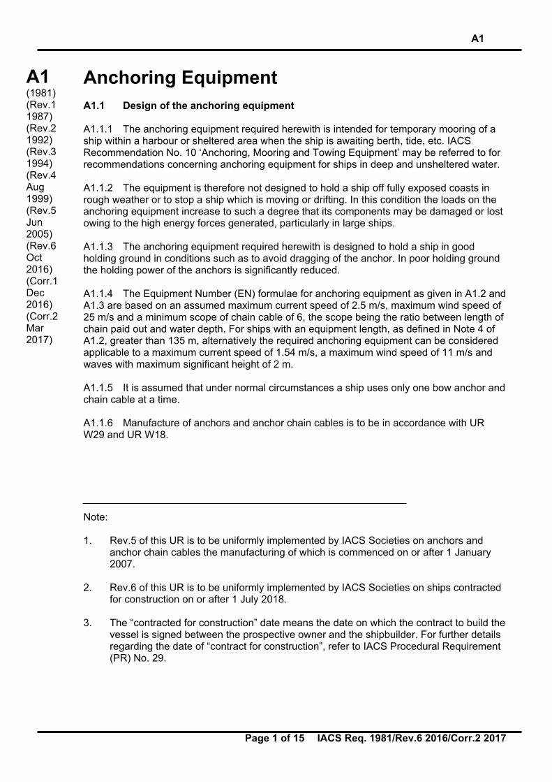
where: ∆ = moulded displacement, in t, to the Summer Load waterline, B = moulded breadth, in m, h = effective height, in m, from the Summer Load waterline to the top of the uppermost
house; for the lowest tier h is to be measured at centreline from the upper deck or from a notional deck line where there is local discontinuity in the upper deck, see figure below for an example.
= iha
a = distance, in m, from the Summer Load waterline amidships to the upper deck, hi = height, in m, on the centreline of each tier of houses having a breadth greater than B/4, A = side projected area, in m2, of the hull, superstructures and houses above the Summer
Load waterline which are within the equipment length of the ship and also have a breadth greater than B/4.
Summer Load waterline
a
h1
h2
h3
Notional deck line
Upper deck
A1
Page 3 of 15 IACS Req. 1981/Rev.6 2016/Corr.2 2017
A1 (cont)
Notes: 1. When calculating h, sheer and trim are to be ignored, i.e. h is the sum of freeboard
amidships plus the height (at centreline) of each tier of houses having a breadth greater than B/4.
2. If a house having a breadth greater than B/4 is above a house with a breadth of B/4 or
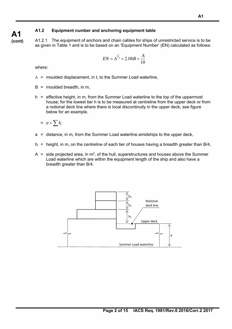
less, then the wide house is to be included but the narrow house ignored. 3. Screens or bulwarks 1.5 m or more in height are to be regarded as parts of houses
when determining h and A. The height of the hatch coamings and that of any deck cargo, such as containers, may be disregarded when determining h and A.
With regard to determining A, when a bulwark is more than 1.5 m high, the area shown below as A2 is to be included in A.
4. The equipment length of the ship is the length between perpendiculars but is not to be
less than 96% nor greater than 97% of the extreme length on the Summer Load waterline (measured from the forward end of the waterline).
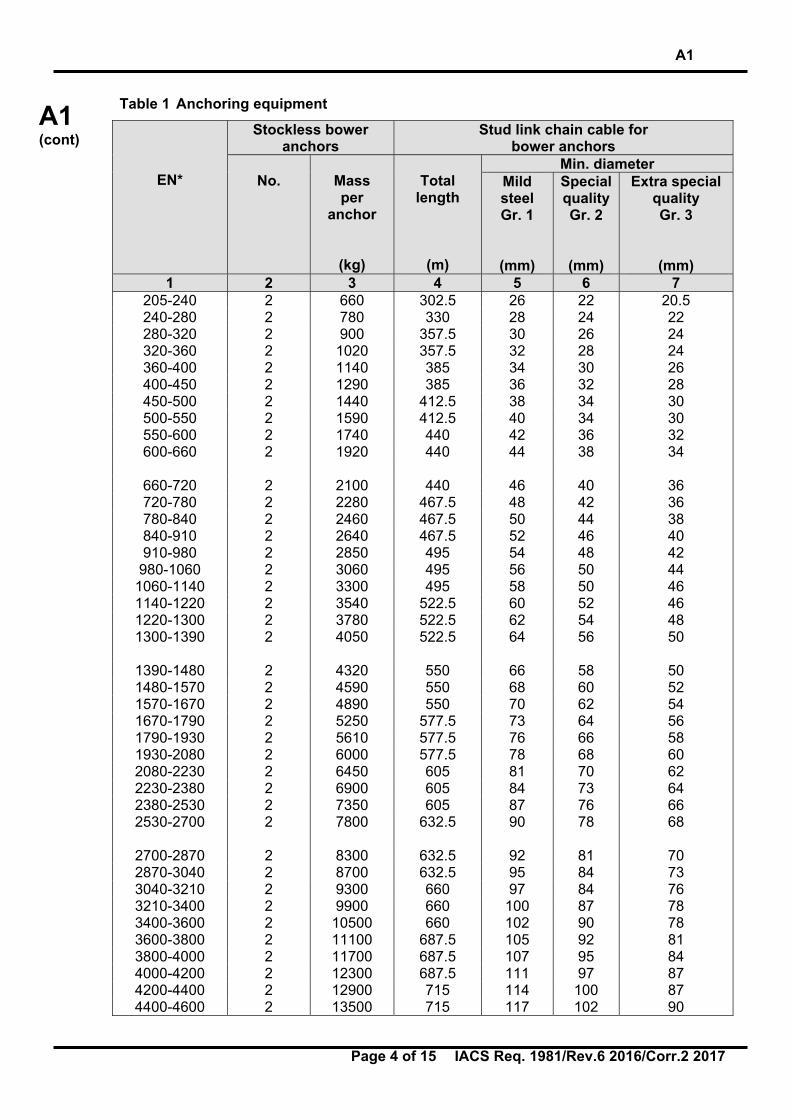
A1.2.2 The total length of chain given in Table 1 - col. 4 - is to be divided in approximately equal parts between the two bower anchors. A1.2.3 For ships of restricted service, the equipment is to be provided at the discretion of the Society.
A1
Page 4 of 15 IACS Req. 1981/Rev.6 2016/Corr.2 2017
A1 (cont)
Table 1 Anchoring equipment
EN*
Stockless bower anchors
Stud link chain cable for bower anchors
No.
Mass per
anchor
(kg)
Total
length
(m)
Min. diameter Mild steel Gr. 1
(mm)
Special quality Gr. 2
(mm)
Extra special quality Gr. 3
(mm) 1 2 3 4 5 6 7
205-240 2 660 302.5 26 22 20.5 240-280 2 780 330 28 24 22 280-320 2 900 357.5 30 26 24 320-360 2 1020 357.5 32 28 24 360-400 2 1140 385 34 30 26 400-450 2 1290 385 36 32 28 450-500 2 1440 412.5 38 34 30 500-550 2 1590 412.5 40 34 30 550-600 2 1740 440 42 36 32 600-660 2 1920 440 44 38 34
660-720 2 2100 440 46 40 36 720-780 2 2280 467.5 48 42 36 780-840 2 2460 467.5 50 44 38 840-910 2 2640 467.5 52 46 40 910-980 2 2850 495 54 48 42
980-1060 2 3060 495 56 50 44 1060-1140 2 3300 495 58 50 46 1140-1220 2 3540 522.5 60 52 46 1220-1300 2 3780 522.5 62 54 48 1300-1390 2 4050 522.5 64 56 50
1390-1480 2 4320 550 66 58 50 1480-1570 2 4590 550 68 60 52 1570-1670 2 4890 550 70 62 54 1670-1790 2 5250 577.5 73 64 56 1790-1930 2 5610 577.5 76 66 58 1930-2080 2 6000 577.5 78 68 60 2080-2230 2 6450 605 81 70 62 2230-2380 2 6900 605 84 73 64 2380-2530 2 7350 605 87 76 66 2530-2700 2 7800 632.5 90 78 68
2700-2870 2 8300 632.5 92 81 70 2870-3040 2 8700 632.5 95 84 73 3040-3210 2 9300 660 97 84 76 3210-3400 2 9900 660 100 87 78 3400-3600 2 10500 660 102 90 78 3600-3800 2 11100 687.5 105 92 81 3800-4000 2 11700 687.5 107 95 84 4000-4200 2 12300 687.5 111 97 87 4200-4400 2 12900 715 114 100 87 4400-4600 2 13500 715 117 102 90
A1
Page 5 of 15 IACS Req. 1981/Rev.6 2016/Corr.2 2017
A1 (cont)
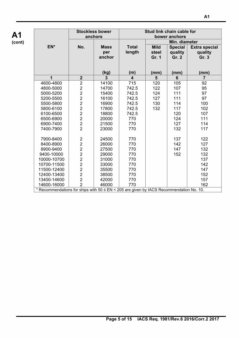
EN*
Stockless bower anchors
Stud link chain cable for bower anchors
No.
Mass per
anchor
(kg)
Total
length
(m)
Min. diameter Mild steel Gr. 1
(mm)
Special quality Gr. 2
(mm)
Extra special quality Gr. 3
(mm) 1 2 3 4 5 6 7
4600-4800 2 14100 715 120 105 92 4800-5000 2 14700 742.5 122 107 95 5000-5200 2 15400 742.5 124 111 97 5200-5500 2 16100 742.5 127 111 97 5500-5800 2 16900 742.5 130 114 100 5800-6100 2 17800 742.5 132 117 102 6100-6500 2 18800 742.5 120 107 6500-6900 2 20000 770 124 111 6900-7400 2 21500 770 127 114 7400-7900 2 23000 770 132 117
7900-8400 2 24500 770 137 122 8400-8900 2 26000 770 142 127 8900-9400 2 27500 770 147 132
9400-10000 2 29000 770 152 132 10000-10700 2 31000 770 137 10700-11500 2 33000 770 142 11500-12400 2 35500 770 147 12400-13400 2 38500 770 152 13400-14600 2 42000 770 157 14600-16000 2 46000 770 162
* Recommendations for ships with 50 ≤ EN < 205 are given by IACS Recommendation No. 10.
A1
Page 6 of 15 IACS Req. 1981/Rev.6 2016/Corr.2 2017
A1 (cont)
A1.3 Anchoring equipment for tugs and dredgers A1.3.1 Equipment for tugs For tugs of unrestricted service the equipment is to be provided in compliance with the present requirement. However, for determination of the Equipment Number, in the formula given in A1.2, the following may be substituted for the term 2.0 hB
)(0.2 iibhaB
where a, B and hi are defined in A1.2 and bi is the breadth, in m, of the widest superstructure or deckhouse of each tier having a breadth greater than B/4.
For tugs of restricted service the equipment is to be provided at the discretion of the Society. A1.3.2 Equipment for dredgers For dredgers of unrestricted service having normal ship shape of underwater part of the hull the anchoring equipment is to be provided in accordance with this Unified Requirement. When calculating the Equipment Number bucket ladders and gallows are not to be included. If however a dredger has unusual design of the underwater part of the hull, the Society is free to modify the requirements to anchoring equipment. For dredgers of limited service, the equipment is to be provided at the discretion of the Society.

A1
Page 7 of 15 IACS Req. 1981/Rev.6 2016/Corr.2 2017
A1 (cont)
A1.4 Anchors A1.4.1 Types of anchors A1.4.1.1 Ordinary stockless anchors (a) Ordinary anchors of ‘stockless’ type are to be generally adopted and they are to be of
appropriate design in compliance with the rules or practice of the Society. (b) The mass of the heads of stockless anchors including pins and fittings are not to be
less than 60% of the total mass of the anchor. (c) The mass, per anchor, of bower anchor given in Table 1 is required for anchors of equal
mass. The mass of individual anchors may vary to 7% of the Table mass provided that the total mass of anchors is not less than that required for anchors of equal mass.
A1.4.1.2 High Holding Power (HHP) anchors (a) A ‘high holding power’ anchor is an anchor with a holding power of at least twice that of
an ordinary stockless anchor of the same mass. A HHP anchor is to be suitable for ship’s use and is not to require prior adjustment or special placement on the sea bottom.
(b) When special type of anchors designated ‘high holding power anchor’ of proven
superior holding ability are used as bower anchors, the mass of each anchor may be 75% of the mass required for ordinary stockless bower anchors in the Table 1.
(c) For approval and/or acceptance as a HHP anchor satisfactory full scale tests according
to A1.4.2 are to be made confirming that the anchor has a holding power of at least twice that of an ordinary stockless anchor of the same mass.
A1.4.1.3 Super High Holding Power (SHHP) anchors (a) A ‘super high holding power’ anchor is an anchor with a holding power of at least four
times that of an ordinary stockless anchor of the same mass. A SHHP anchor is suitable for restricted service ships’ use and does not require prior adjustment or special placement on the sea bottom.
(b) The use of SHHP anchors is limited to restricted service ships as defined by the
Society.
The SHHP anchor mass is generally not to exceed 1500kg. (c) The requirement for design of SHHP anchors applies down to EN ≥ 205. For EN < 205
the design criteria for SHHP anchors apply to the anchor mass given in Recommendation No. 10 for ordinary stockless anchors, reduced as permitted in accordance with 1.1 (c) of Recommendation No. 10.
(d) When super high holding power anchors of the proven holding power are used as
bower anchors, the mass of each such anchor may be reduced to not less than 50% of the mass required for ordinary stockless anchors in Table 1.
(e) For approval and/or acceptance as a SHHP anchor satisfactory full scale tests
according to A1.4.2 are to be made confirming that the anchor has a holding power of
A1
Page 8 of 15 IACS Req. 1981/Rev.6 2016/Corr.2 2017
A1 (cont)
at least four times that of an ordinary stockless anchor or at least twice that of a previously approved HHP anchor of the same mass.
A1.4.2 Anchor holding power tests for HHP and SHHP anchors (a) Full scale tests are to be carried out at sea on various types of bottom, normally, soft
mud or silt, sand or gravel and hard clay or similar compounded material. The tests are to be applied to anchors of mass which are as far as possible representative of the full range of sizes proposed.
(b) For a definite group within the range, the two anchors selected for testing (ordinary
stockless anchor and HHP anchor, or ordinary stockless anchor and SHHP anchor, respectively) are to be of approximately the same mass and tested in association with the size of chain required for that anchor mass. Where an ordinary stockless anchor is not available, for testing of HHP anchors a previously approved HHP anchor may be used in its place. For testing of SHHP anchors, a previously approved HHP or SHHP anchor may be used in place of an ordinary stockless anchor. The length of the cable with each anchor is to be such that the pull on the shank remains horizontal. For this purpose a scope of 10 is considered normal but a scope of not less than 6 may be accepted. Scope is defined as the ratio of length of cable to depth of water.
(c) Three tests are to be taken for each anchor and each type of bottom. The stability of the
anchor and ease of breaking out are to be noted where possible. Tests are to be carried out from a tug but alternatively shore based tests may be accepted. The pull is to be measured by dynamometer. Measurements of pull, based on the RPM/bollard pull curve of the tug may be accepted as an alternative to a dynamometer.
(d) For approval and/or acceptance for a range of HHP anchor sizes, tests are to be carried
out for at least two anchor sizes. The mass of the maximum size approved is not to be more than 10 times the mass of the largest size tested.
(e) For approval and/or acceptance for a range of SHHP anchor sizes, at least three
anchor sizes are to be tested, indicative of the bottom, middle and top of the mass range.
(f) The holding power test load is not to exceed the proof load of the anchor. A1.4.3 Installation of the anchors on board The bower anchors are to be connected to their cables and positioned on board ready for use. A1.4.4 Proof testing of anchors A1.4.4.1 Testing of ordinary anchors (a) Anchors of all sizes are to be proof tested with the test loads stipulated in the Table 2. (b) The proof load is to be applied on the arm or on the palm at a spot which, measured
from the extremity of the bill, is one-third of the distance between it and the centre of the crown, see figure below. In the case of stockless anchors, both arms are to be tested at the same time, first on one side of the shank, then reversed and tested on the other.

A1
Page 9 of 15 IACS Req. 1981/Rev.6 2016/Corr.2 2017
A1 (cont)
(c) Before application of proof test load the anchors are to be examined to be sure that castings are reasonably free of surface imperfections of harmful nature. After proof load testing the anchors are to be examined for cracks and other defects. On completion of the proof load tests the anchors made in more than one piece are to be examined for free rotation of their heads over the complete angle. In every test the difference between the gauge lengths (as shown in figures) where one-tenth of the required load was applied first and where the load has been reduced to one-tenth of the required load from the full load may be permitted not to exceed 1%.
Stocked Anchor Stockless Anchor A1.4.4.2 Testing of HHP anchors The HHP anchor is to be proof tested with load required by Table 2 for an anchor mass equal to 1.33 times the actual mass of the HHP anchor. The proof loading procedure and examination procedure for HHP anchors are to comply with those for ordinary anchors, A1.4.4.1 (b) and (c). A1.4.4.3 Testing of SHHP anchors (a) The SHHP anchor is to be proof tested with the load required by Table 2 for an anchor
mass equal to twice the actual mass of the SHHP anchor. The proof loading procedure and examination procedure for SHHP anchors are to comply with those for ordinary anchors, A1.4.4.1 (b) and (c).
(b) After the proof load test, all SHHP anchors are to be surface inspected by the dye
penetrant method or by the magnetic particle method. All surfaces of cast steel anchors are to be surface inspected. All cast steel anchors are to be examined by UT in way of areas where feeder heads and risers have been removed and where weld repairs have been carried out. The surface inspections and UT inspections are to follow Recommendation No. 69 ‘Guidelines for NDE of Marine Steel Castings’. Welded steel anchors are to be inspected at the welds. At sections of high load or at suspect areas, the Society may impose volumetric non-destructive examination, e.g, ultrasonic inspection or radiographic inspection.
(c) At the discretion of the Society, additional tests of the anchor may be required. These
tests include the hammering test and the drop test, and are usually applied to cast steel anchors.

A1
Page 10 of 15 IACS Req. 1981/Rev.6 2016/Corr.2 2017
A1 (cont)
Table 2 Proof loads for anchors Mass of anchor
(kg)
Proof load
*
(kN)
Mass of anchor
(kg)
Proof load
*
(kN)
Mass of anchor
(kg)
Proof load
*
(kN)
Mass of anchor
(kg)
Proof load
*
(kN) 50 23.2 1250 239 5000 661 12500 1130 55 25.2 1300 247 5100 669 13000 1160 60 27.1 1350 255 5200 677 13500 1180 65 28.9 1400 262 5300 685 14000 1210
70 30.7 1450 270 5400 691 14500 1230 75 32.4 1500 278 5500 699 15000 1260 80 33.9 1600 292 5600 706 15500 1270 90 36.3 1700 307 5700 713 16000 1300
100 39.1 1800 321 5800 721 16500 1330 120 44.3 1900 335 5900 728 17000 1360 140 49.0 2000 349 6000 735 17500 1390 160 53.3 2100 362 6100 740 18000 1410
180 57.4 2200 376 6200 747 18500 1440 200 61.3 2300 388 6300 754 19000 1470 225 65.8 2400 401 6400 760 19500 1490 250 70.4 2500 414 6500 767 20000 1520
275 74.9 2600 427 6600 773 21000 1570 300 79.5 2700 438 6700 779 22000 1620 325 84.1 2800 450 6800 786 23000 1670 350 88.8 2900 462 6900 794 24000 1720
375 93.4 3000 474 7000 804 25000 1770 400 97.9 3100 484 7200 818 26000 1800 425 103 3200 495 7400 832 27000 1850 450 107 3300 506 7600 845 28000 1900
475 112 3400 517 7800 861 29000 1940 500 116 3500 528 8000 877 30000 1990 550 124 3600 537 8200 892 31000 2030 600 132 3700 547 8400 908 32000 2070
650 140 3800 557 8600 922 34000 2160 700 149 3900 567 8800 936 36000 2250 750 158 4000 577 9000 949 38000 2330 800 166 4100 586 9200 961 40000 2410
850 175 4200 595 9400 975 42000 2490 900 182 4300 604 9600 987 44000 2570 950 191 4400 613 9800 998 46000 2650
1000 199 4500 622 10000 1010 48000 2730
1050 208 4600 631 10500 1040 1100 216 4700 638 11000 1070 1150 224 4800 645 11500 1090 1200 231 4900 653 12000 1110
* Proof loads for intermediate mass are to be determined by linear interpolation.
A1
Page 11 of 15 IACS Req. 1981/Rev.6 2016/Corr.2 2017
A1 (cont)
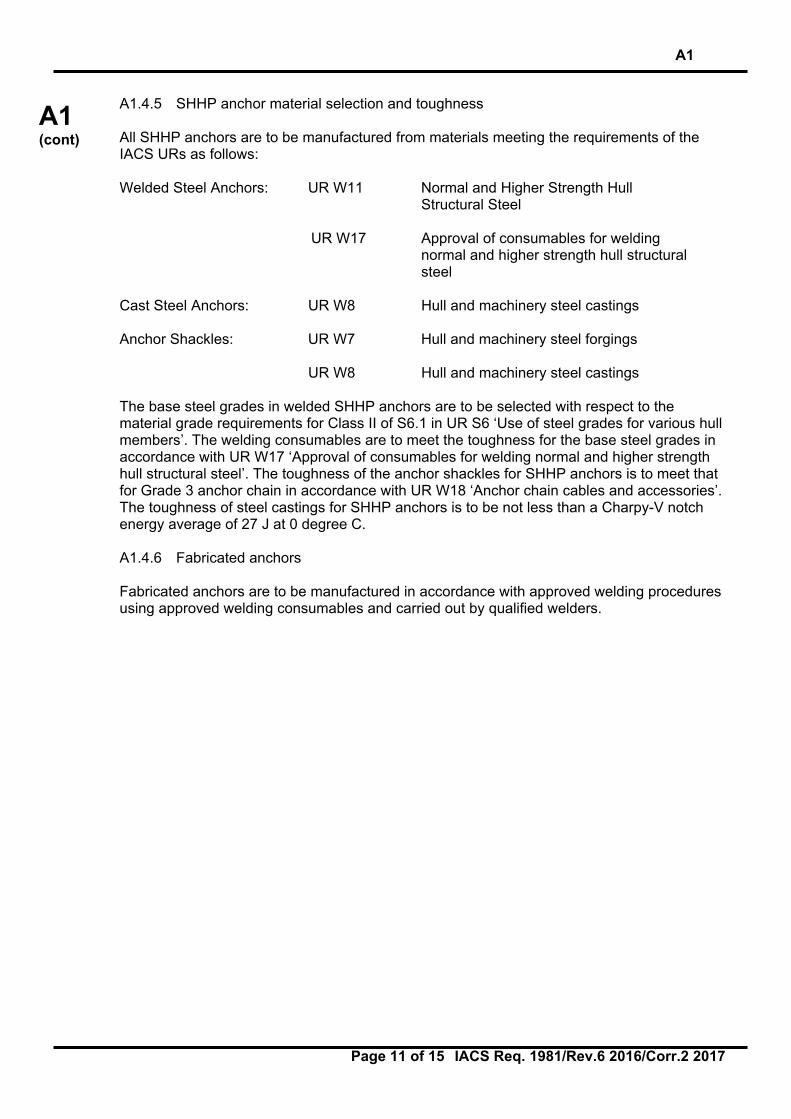
A1.4.5 SHHP anchor material selection and toughness All SHHP anchors are to be manufactured from materials meeting the requirements of the IACS URs as follows: Welded Steel Anchors: UR W11 Normal and Higher Strength Hull
Structural Steel
UR W17 Approval of consumables for welding normal and higher strength hull structural steel
Cast Steel Anchors: UR W8 Hull and machinery steel castings Anchor Shackles: UR W7 Hull and machinery steel forgings
UR W8 Hull and machinery steel castings
The base steel grades in welded SHHP anchors are to be selected with respect to the material grade requirements for Class II of S6.1 in UR S6 ‘Use of steel grades for various hull members’. The welding consumables are to meet the toughness for the base steel grades in accordance with UR W17 ‘Approval of consumables for welding normal and higher strength hull structural steel’. The toughness of the anchor shackles for SHHP anchors is to meet that for Grade 3 anchor chain in accordance with UR W18 ‘Anchor chain cables and accessories’. The toughness of steel castings for SHHP anchors is to be not less than a Charpy-V notch energy average of 27 J at 0 degree C. A1.4.6 Fabricated anchors Fabricated anchors are to be manufactured in accordance with approved welding procedures using approved welding consumables and carried out by qualified welders.
A1
Page 12 of 15 IACS Req. 1981/Rev.6 2016/Corr.2 2017
A1 (cont)
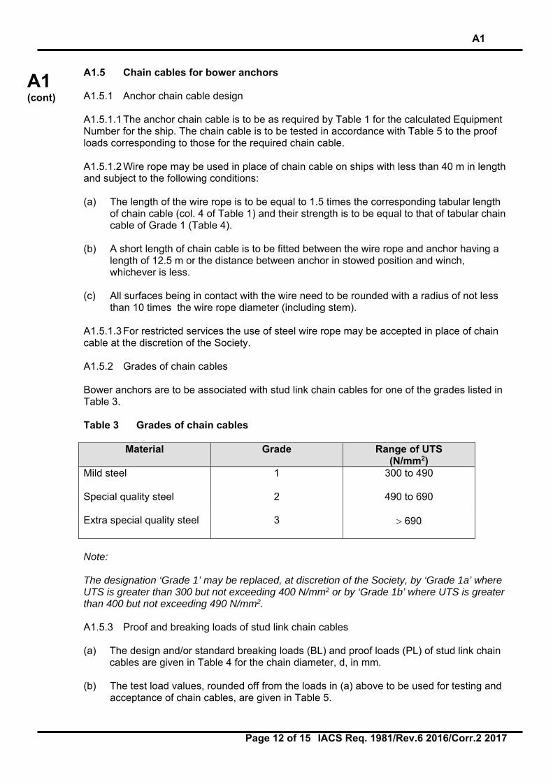
A1.5 Chain cables for bower anchors A1.5.1 Anchor chain cable design A1.5.1.1 The anchor chain cable is to be as required by Table 1 for the calculated Equipment Number for the ship. The chain cable is to be tested in accordance with Table 5 to the proof loads corresponding to those for the required chain cable. A1.5.1.2 Wire rope may be used in place of chain cable on ships with less than 40 m in length and subject to the following conditions: (a) The length of the wire rope is to be equal to 1.5 times the corresponding tabular length
of chain cable (col. 4 of Table 1) and their strength is to be equal to that of tabular chain cable of Grade 1 (Table 4).
(b) A short length of chain cable is to be fitted between the wire rope and anchor having a
length of 12.5 m or the distance between anchor in stowed position and winch, whichever is less.
(c) All surfaces being in contact with the wire need to be rounded with a radius of not less
than 10 times the wire rope diameter (including stem). A1.5.1.3 For restricted services the use of steel wire rope may be accepted in place of chain cable at the discretion of the Society. A1.5.2 Grades of chain cables Bower anchors are to be associated with stud link chain cables for one of the grades listed in Table 3. Table 3 Grades of chain cables
Material Grade Range of UTS (N/mm2)
Mild steel 1 300 to 490
Special quality steel 2 490 to 690
Extra special quality steel 3 690
Note: The designation ‘Grade 1’ may be replaced, at discretion of the Society, by ‘Grade 1a’ where UTS is greater than 300 but not exceeding 400 N/mm2 or by ‘Grade 1b’ where UTS is greater than 400 but not exceeding 490 N/mm2. A1.5.3 Proof and breaking loads of stud link chain cables (a) The design and/or standard breaking loads (BL) and proof loads (PL) of stud link chain
cables are given in Table 4 for the chain diameter, d, in mm. (b) The test load values, rounded off from the loads in (a) above to be used for testing and
acceptance of chain cables, are given in Table 5.
A1
Page 13 of 15 IACS Req. 1981/Rev.6 2016/Corr.2 2017
A1 (cont)
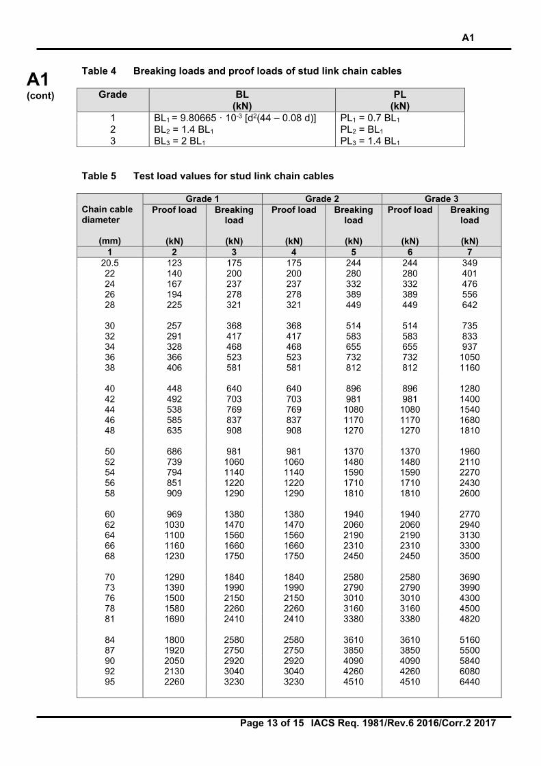
Table 4 Breaking loads and proof loads of stud link chain cables
Grade BL (kN)
PL (kN)
1 BL1 = 9.80665 · 10-3 [d2(44 – 0.08 d)] PL1 = 0.7 BL1 2 BL2 = 1.4 BL1 PL2 = BL1 3 BL3 = 2 BL1 PL3 = 1.4 BL1
Table 5 Test load values for stud link chain cables Chain cable diameter
(mm)
Grade 1 Grade 2 Grade 3 Proof load
(kN)
Breaking load
(kN)
Proof load
(kN)
Breaking load
(kN)
Proof load
(kN)
Breaking load
(kN)
1 2 3 4 5 6 7 20.5 123 175 175 244 244 349 22 140 200 200 280 280 401 24 167 237 237 332 332 476 26 194 278 278 389 389 556 28 225 321 321 449 449 642
30 257 368 368 514 514 735 32 291 417 417 583 583 833 34 328 468 468 655 655 937 36 366 523 523 732 732 1050 38 406 581 581 812 812 1160
40 448 640 640 896 896 1280 42 492 703 703 981 981 1400 44 538 769 769 1080 1080 1540 46 585 837 837 1170 1170 1680 48 635 908 908 1270 1270 1810
50 686 981 981 1370 1370 1960 52 739 1060 1060 1480 1480 2110 54 794 1140 1140 1590 1590 2270 56 851 1220 1220 1710 1710 2430 58 909 1290 1290 1810 1810 2600
60 969 1380 1380 1940 1940 2770 62 1030 1470 1470 2060 2060 2940 64 1100 1560 1560 2190 2190 3130 66 1160 1660 1660 2310 2310 3300 68 1230 1750 1750 2450 2450 3500
70 1290 1840 1840 2580 2580 3690 73 1390 1990 1990 2790 2790 3990 76 1500 2150 2150 3010 3010 4300 78 1580 2260 2260 3160 3160 4500 81 1690 2410 2410 3380 3380 4820
84 1800 2580 2580 3610 3610 5160 87 1920 2750 2750 3850 3850 5500 90 2050 2920 2920 4090 4090 5840 92 2130 3040 3040 4260 4260 6080 95 2260 3230 3230 4510 4510 6440

A1
Page 14 of 15 IACS Req. 1981/Rev.6 2016/Corr.2 2017
A1 (cont)
Chain cable diameter
(mm)
Grade 1 Grade 2 Grade 3 Proof load
(kN)
Breaking load
(kN)
Proof load
(kN)
Breaking load
(kN)
Proof load
(kN)
Breaking load
(kN)
1 2 3 4 5 6 7 97 2340 3340 3340 4680 4680 6690
100 2470 3530 3530 4940 4940 7060 102 2560 3660 3660 5120 5120 7320 105 2700 3850 3850 5390 5390 7700 107 2790 3980 3980 5570 5570 7960
111 2970 4250 4250 5940 5940 8480 114 3110 4440 4440 6230 6230 8890 117 3260 4650 4650 6510 6510 9300 120 3400 4850 4850 6810 6810 9720 122 3500 5000 5000 7000 7000 9990
124 3600 5140 5140 7200 7200 10280 127 3750 5350 5350 7490 7490 10710 130 3900 5570 5570 7800 7800 11140 132 4000 5720 5720 8000 8000 11420 137 4260 6080 6080 8510 8510 12160
142 4520 6450 6450 9030 9030 12910 147 4790 6840 6840 9560 9560 13660 152 5050 7220 7220 10100 10100 14430 157 5320 7600 7600 10640 10640 15200 162 5590 7990 7990 11170 11170 15970
A1.6 Permissible wear down of stud link chain cable for bower anchors When a length of chain cable is so worn that the mean diameter of a link, at its most worn part, is reduced by 12% or more from its required nominal diameter it is to be renewed. The mean diameter is half the value of the sum of the minimum diameter found in one cross-section of the link and of the diameter measured in a perpendicular direction in the same cross-section. A1.7 Hull supporting structure of anchor windlass and chain stopper The hull supporting structure of anchor windlass and chain stopper is to be sufficient to accommodate the operating and sea loads. A1.7.1 Operating loads The operating loads are to be taken not less than: • for chain stoppers, 80% of the chain cable breaking load • for windlasses, where no chain stopper is fitted or the chain stopper is attached to the
windlass, 80% of the chain cable breaking load • for windlasses, where chain stoppers are fitted but not attached to the windlass, 45% of
the chain cable breaking load

A1
Page 15 of 15 IACS Req. 1981/Rev.6 2016/Corr.2 2017
A1 (cont)
The operating loads are to be applied in the direction of the chain cable. A1.7.2 Sea loads The sea loads are to be taken according to UR S27. A1.7.3 Permissible stress The permissible stresses for hull supporting structures of windlass and chain stopper are to be taken as defined by the Society. However, the stresses, based on gross thickness, are not to be greater than the following permissible values: • Normal stress: 1.00 ReH • Shear stress: 0.60 ReH where ReH is the specified minimum yield stress of the material.
End of Document
A2
Page 1 of 11 IACS Req. 2004/Rev.4 2016/Corr.2 2017
A2 (cont)
Shipboard fittings and supporting hull structures associated with towing and mooring on conventional ships A2.0 Application and definitions Conventional ships are to be provided with arrangements, equipment and fittings of sufficient safe working load to enable the safe conduct of all towing and mooring operations associated with the normal operations of the ship. This Unified Requirement is to apply to design and construction of shipboard fittings and supporting structures used for the normal towing and mooring operations. Normal towing means towing operations necessary for manoeuvring in ports and sheltered waters associated with the normal operations of the ship. For ships, not subject to SOLAS Regulation II-1/3-4 Paragraph 1, but intended to be fitted with equipment for towing by another ship or a tug, e.g. such as to assist the ship in case of emergency as given in SOLAS Regulation II-1/3-4 Paragraph 2, the requirements designated as ‘other towing’ in this Unified Requirement are to be applied to design and construction of those shipboard fittings and supporting hull structures. This Unified Requirement is not applicable to design and construction of shipboard fittings and supporting hull structures used for special towing services defined as: • Escort towing: Towing service, in particular, for laden oil tankers or LNG carriers,
required in specific estuaries. Its main purpose is to control the ship in case of failures of the propulsion or steering system. It should be referred to local escort requirements and guidance given by, e.g., the Oil Companies International Marine Forum (OCIMF).
Note: 1) Corr.1 Feb 2004 is to be applied by all Member Societies and Associates to ships contracted for construction after 1 Jan 2005. 2) The “contracted for construction” date means the date on which the contract to build the vessel is signed between the prospective owner and the shipbuilder. For further details regarding the date of “contract for construction”, refer to IACS Procedural Requirement (PR) No. 29. 3) Revision 2 of this UR is to be applied by all IACS Members and Associates to ships contracted for construction from 1 January 2007. 4) Revision 3 of this UR is to be uniformly implemented by all IACS Members and Associates to ships contracted for construction from 1 January 2007. 5) Revision 4 of this UR is to be uniformly implemented by all IACS Societies to ships contracted for construction from 1 July 2018.
A2 (Jan 2004) (Corr.1 Feb 2004) Rev.1 July 2004) (Rev.2 Sept 2006) (Rev.3 July 2007) (Corr.1 Sept 2014) (Rev.4 Oct 2016) (Corr.1 Dec 2016) (Corr.2 Mar 2017)

A2
Page 2 of 11 IACS Req. 2004/Rev.4 2016/Corr.2 2017
A2 (cont)
• Canal transit towing: Towing service for ships transiting canals, e.g. the Panama Canal. It should be referred to local canal transit requirements.
• Emergency towing for tankers: Towing service to assist tankers in case of
emergency. For the emergency towing arrangements, ships subject to SOLAS regulation II-1/3-4 Paragraph 1 are to comply with that regulation and resolution MSC.35(63) as may be amended.
IACS Recommendation No. 10 “Anchoring, Mooring and Towing Equipment” may be referred to for recommendations concerning mooring and towing. The net minimum scantlings of the supporting hull structure are to comply with the requirements given in A2.1.5 and A2.2.5. The net thicknesses, tnet, are the member thicknesses necessary to obtain the above required minimum net scantlings. The required gross thicknesses are obtained by adding the corrosion addition, tc, given in A2.4, to tnet. Shipboard fittings are to comply with the requirements given in A2.1.4 and A2.2.4. For shipboard fittings not selected from an accepted industry standard the corrosion addition, tc, and the wear allowance, tw, given in A2.4 and A2.5, respectively, are to be considered. For the purpose of this Unified Requirement the following is defined: • Conventional ships means new displacement-type ships of 500 GT and above,
excluding high speed craft, special purpose ships, and offshore units of all types. As per MSC.266(84), ‘Special purpose ship’ means a mechanically self-propelled ship which by reason of its function carries on board more than 12 special personnel.
• Shipboard fittings mean those components limited to the following: Bollards and bitts,
fairleads, stand rollers, chocks used for normal mooring of the ship and the similar components used for normal or other towing of the ship. Other components such as capstans, winches, etc. are not covered by this Unified Requirement. Any weld or bolt or equivalent device connecting the shipboard fitting to the supporting structure is part of the shipboard fitting and if selected from an industry standard subject to that standard.
• Supporting hull structures means that part of the ship structure on/in which the
shipboard fitting is placed and which is directly submitted to the forces exerted on the shipboard fitting. The supporting hull structure of capstans, winches, etc. used for normal or other towing and mooring operations mentioned above is also subject to this Unified Requirement.
• Industry standard means international standards (ISO, etc.) or standards issued by
national association such as DIN or JMSA, etc. which are recognized in the country where the ship is built.

A2
Page 3 of 11 IACS Req. 2004/Rev.4 2016/Corr.2 2017
A2 (cont)
A2.1 Towing A2.1.1 Strength The strength of shipboard fittings used for normal towing operations at bow, sides and stern and their supporting hull structures are to comply with the requirements of this Unified Requirement. Where a ship is equipped with shipboard fittings intended to be used for other towing services, the strength of these fittings and their supporting hull structures are to comply with the requirements of this Unified Requirement. A2.1.2 Arrangement Shipboard fittings for towing are to be located on stiffeners and/or girders, which are part of the deck construction so as to facilitate efficient distribution of the towing load. Other arrangements may be accepted (for chocks in bulwarks, etc.) provided the strength is confirmed adequate for the intended service. A2.1.3 Load considerations The minimum design load applied to supporting hull structures for shipboard fittings is to be: (1) For normal towing operations, 1.25 times the intended maximum towing load (e.g. static
bollard pull) as indicated on the towing and mooring arrangements plan, (2) For other towing service, the minimum breaking strength of the tow line according to
IACS Recommendation No. 10 “Anchoring, Mooring and Towing Equipment” (see Notes),
(3) For fittings intended to be used for, both, normal and other towing operations, the
greater of the design loads according to (1) and (2). Notes: 1. Side projected area including that of deck cargoes as given by the loading manual is to
be taken into account for selection of towing lines and the loads applied to shipboard fittings and supporting hull structure.
2. The increase of the minimum breaking strength for synthetic ropes according to
Recommendation No. 10 needs not to be taken into account for the loads applied to shipboard fittings and supporting hull structure.
When a safe towing load TOW greater than that determined according to A2.1.6 is requested by the applicant, then the design load is to be increased in accordance with the appropriate TOW/design load relationship given by A2.1.3 and A2.1.6. The design load is to be applied to fittings in all directions that may occur by taking into account the arrangement shown on the towing and mooring arrangements plan. Where the towing line takes a turn at a fitting the total design load applied to the fitting is equal to the resultant of the design loads acting on the line, see figure below. However, in no case does the design load applied to the fitting need to be greater than twice the design load on the line.

A2
Page 4 of 11 IACS Req. 2004/Rev.4 2016/Corr.2 2017
A2 (cont)
A2.1.4 Shipboard fittings Shipboard fittings may be selected from an industry standard accepted by the Society and at least based on the following loads. (1) For normal towing operations, the intended maximum towing load (e.g. static bollard
pull) as indicated on the towing and mooring arrangements plan, (2) For other towing service, the minimum breaking strength of the tow line according to
IACS Recommendation No. 10 “Anchoring, Mooring and Towing Equipment” (see Notes in A2.1.3),
(3) For fittings intended to be used for, both, normal and other towing operations, the
greater of the loads according to (1) and (2). Towing bitts (double bollards) may be chosen for the towing line attached with eye splice if the industry standard distinguishes between different methods to attach the line, i.e. figure-of-eight or eye splice attachment. When the shipboard fitting is not selected from an accepted industry standard, the strength of the fitting and of its attachment to the ship is to be in accordance with A2.1.3 and A2.1.5. Towing bitts (double bollards) are required to resist the loads caused by the towing line attached with eye splice. For strength assessment beam theory or finite element analysis using net scantlings is to be applied, as appropriate. Corrosion additions are to be as defined in A2.4. A wear down allowance is to be included as defined in A2.5. At the discretion of the Society, load tests may be accepted as alternative to strength assessment by calculations. A2.1.5 Supporting hull structure The design load applied to supporting hull structure is to be in accordance with A2.1.3. The reinforced members beneath shipboard fittings are to be effectively arranged for any variation of direction (horizontally and vertically) of the towing forces acting upon the shipboard fittings, see figure below for a sample arrangement. Proper alignment of fitting and supporting hull structure is to be ensured.

A2
Page 5 of 11 IACS Req. 2004/Rev.4 2016/Corr.2 2017
A2 (cont)
The acting point of the towing force on shipboard fittings is to be taken at the attachment point of a towing line or at a change in its direction. For bollards and bitts the attachment point of the towing line is to be taken not less than 4/5 of the tube height above the base, see figure below.
Allowable stresses under the design load conditions as specified in A2.1.3 are as follows: (1) For strength assessment with beam theory or grillage analysis: Normal stress: 100% of the specified minimum yield point of the material; Shearing stress: 60% of the specified minimum yield point of the material. Normal stress is the sum of bending stress and axial stress with the corresponding
shearing stress acting perpendicular to the normal stress. No stress concentration factors being taken into account.
(2) For strength assessment with finite element analysis: Equivalent stress: 100% of the specified minimum yield point of the material. For strength calculations by means of finite elements, the geometry is to be idealized as realistically as possible. The ratio of element length to width is not to exceed 3. Girders are to be modelled using shell or plane stress elements. Symmetric girder flanges may be modelled by beam or truss elements. The element height of girder webs must not exceed one-third of the web height. In way of small openings in girder webs the web thickness is to be reduced to a mean thickness over the web height. Large openings are to be modelled. Stiffeners may be modelled by using shell, plane stress, or beam elements. Stresses are to be read from the centre of the individual element. For shell elements the stresses are to be evaluated at the mid plane of the element.
Fitting on deck (e.g. bollard, chock)
Main hull structure (e.g. web frames, deck stiffeners)
Reinforcing members beneath shipboard fittings
DESIGN LOAD ON LINE

A2
Page 6 of 11 IACS Req. 2004/Rev.4 2016/Corr.2 2017
A2 (cont)
A2.1.6 Safe Towing Load (TOW) 1) The safe towing load (TOW) is the load limit for towing purpose. 2) TOW used for normal towing operations is not to exceed 80% of the design load per
A2.1.3 (1). 3) TOW used for other towing operations is not to exceed 80% of the design load
according to A2.1.3 (2). 4) For fittings used for both normal and other towing operations, the greater of the safe
towing loads according to 2) and 3) is to be used. 5) For fittings intended to be used for, both, towing and mooring, A2.2 applies to mooring. 6) TOW, in t, of each shipboard fitting is to be marked (by weld bead or equivalent) on the
deck fittings used for towing. For fittings intended to be used for, both, towing and mooring, SWL, in t, according to A2.2.6 is to be marked in addition to TOW.
7) The above requirements on TOW apply for the use with no more than one line. If not
otherwise chosen, for towing bitts (double bollards) TOW is the load limit for a towing line attached with eye-splice.
8) The towing and mooring arrangements plan mentioned in A2.3 is to define the method
of use of towing lines.

A2
Page 7 of 11 IACS Req. 2004/Rev.4 2016/Corr.2 2017
A2 (cont)
A2.2 Mooring A2.2.1 Strength The strength of shipboard fittings used for mooring operations and of their supporting hull structures as well as the strength of supporting hull structures of winches and capstans is to comply with the requirements of this Unified Requirement. A2.2.2 Arrangement Shipboard fittings, winches and capstans for mooring are to be located on stiffeners and/or girders, which are part of the deck construction so as to facilitate efficient distribution of the mooring load. Other arrangements may be accepted (for chocks in bulwarks, etc.) provided the strength is confirmed adequate for the service. A2.2.3 Load considerations 1) The minimum design load applied to supporting hull structures for shipboard fittings is
to be 1.15 times the minimum breaking strength of the mooring line according to IACS Recommendation No. 10 “Anchoring, Mooring and Towing Equipment” (see Notes).
2) The minimum design load applied to supporting hull structures for winches is to be 1.25
times the intended maximum brake holding load, where the maximum brake holding load is to be assumed not less than 80% of the minimum breaking strength of the mooring line according to IACS Recommendation No. 10 “Anchoring, Mooring and Towing Equipment”, see Notes. For supporting hull structures of capstans, 1.25 times the maximum hauling-in force is to be taken as the minimum design load.
3) When a safe working load SWL greater than that determined according to A2.2.6 is
requested by the applicant, then the design load is to be increased in accordance with the appropriate SWL/design load relationship given by A2.2.3 and A2.2.6.
4) The design load is to be applied to fittings in all directions that may occur by taking into
account the arrangement shown on the towing and mooring arrangements plan. Where the mooring line takes a turn at a fitting the total design load applied to the fitting is equal to the resultant of the design loads acting on the line, refer to the figure in A2.1.3. However, in no case does the design load applied to the fitting need to be greater than twice the design load on the line.
Notes: 1. If not otherwise specified by Recommendation No. 10, side projected area including
that of deck cargoes as given by the loading manual is to be taken into account for selection of mooring lines and the loads applied to shipboard fittings and supporting hull structure.
2. The increase of the minimum breaking strength for synthetic ropes according to
Recommendation No. 10 needs not to be taken into account for the loads applied to shipboard fittings and supporting hull structure.
A2.2.4 Shipboard fittings
Shipboard fittings may be selected from an industry standard accepted by the Society and at least based on the minimum breaking strength of the mooring line according to IACS Recommendation No. 10 “Anchoring, Mooring and Towing Equipment” (see Notes in A2.2.3).

A2
Page 8 of 11 IACS Req. 2004/Rev.4 2016/Corr.2 2017
A2 (cont)
Mooring bitts (double bollards) are to be chosen for the mooring line attached in figure-of-eight fashion if the industry standard distinguishes between different methods to attach the line, i.e. figure-of-eight or eye splice attachment. When the shipboard fitting is not selected from an accepted industry standard, the strength of the fitting and of its attachment to the ship is to be in accordance with A2.2.3 and A2.2.5. Mooring bitts (double bollards) are required to resist the loads caused by the mooring line attached in figure-of-eight fashion, see Note. For strength assessment beam theory or finite element analysis using net scantlings is to be applied, as appropriate. Corrosion additions are to be as defined in A2.4. A wear down allowance is to be included as defined in A2.5. At the discretion of the classification Society, load tests may be accepted as alternative to strength assessment by calculations. Note: With the line attached to a mooring bitt in the usual way (figure-of-eight fashion), either of the two posts of the mooring bitt can be subjected to a force twice as large as that acting on the mooring line. Disregarding this effect, depending on the applied industry standard and fitting size, overload may occur. A2.2.5 Supporting hull structure The design load applied to supporting hull structure is to be in accordance with A2.2.3. The arrangement of reinforced members beneath shipboard fittings, winches and capstans is to consider any variation of direction (horizontally and vertically) of the mooring forces acting upon the shipboard fittings, see figure in A2.1.5 for a sample arrangement. Proper alignment of fitting and supporting hull structure is to be ensured. The acting point of the mooring force on shipboard fittings is to be taken at the attachment point of a mooring line or at a change in its direction. For bollards and bitts the attachment point of the mooring line is to be taken not less than 4/5 of the tube height above the base, see a) in figure below. However, if fins are fitted to the bollard tubes to keep the mooring line as low as possible, the attachment point of the mooring line may be taken at the location of the fins, see b) in figure below.
DESIGN LOAD ON LINE
a)
b)

A2
Page 9 of 11 IACS Req. 2004/Rev.4 2016/Corr.2 2017
A2 (cont)
Allowable stresses under the design load conditions as specified in A2.2.3 are as follows: (1) For strength assessment with beam theory or grillage analysis: Normal stress: 100% of the specified minimum yield point of the material; Shearing stress: 60% of the specified minimum yield point of the material. Normal stress is the sum of bending stress and axial stress with the corresponding
shearing stress acting perpendicular to the normal stress. No stress concentration factors being taken into account.
(2) For strength assessment with finite element analysis: Equivalent stress: 100% of the specified minimum yield point of the material. For strength calculations by means of finite elements, the geometry is to be idealized as realistically as possible. The ratio of element length to width is not to exceed 3. Girders are to be modelled using shell or plane stress elements. Symmetric girder flanges may be modelled by beam or truss elements. The element height of girder webs must not exceed one-third of the web height. In way of small openings in girder webs the web thickness is to be reduced to a mean thickness over the web height. Large openings are to be modelled. Stiffeners may be modelled by using shell, plane stress, or beam elements. Stresses are to be read from the centre of the individual element. For shell elements the stresses are to be evaluated at the mid plane of the element. A2.2.6 Safe Working Load (SWL) 1) The Safe Working Load (SWL) is the load limit for mooring purpose. 2) Unless a greater SWL is requested by the applicant according to A2.2.3 3), the SWL is
not to exceed the minimum breaking strength of the mooring line according to IACS Recommendation No. 10 “Anchoring, Mooring and Towing Equipment”, see Notes in A2.2.3.
3) The SWL, in t, of each shipboard fitting is to be marked (by weld bead or equivalent) on
the deck fittings used for mooring. For fittings intended to be used for, both, mooring and towing, TOW, in t, according to A2.1.6 is to be marked in addition to SWL.
4) The above requirements on SWL apply for the use with no more than one mooring line. 5) The towing and mooring arrangements plan mentioned in A2.3 is to define the method
of use of mooring lines.

A2
Page 10 of 11 IACS Req. 2004/Rev.4 2016/Corr.2 2017
A2 (cont)
A2.3 Towing and mooring arrangements plan 1) The SWL and TOW for the intended use for each shipboard fitting is to be noted in the
towing and mooring arrangements plan available on board for the guidance of the Master. It is to be noted that TOW is the load limit for towing purpose and SWL that for mooring purpose. If not otherwise chosen, for towing bitts it is to be noted that TOW is the load limit for a towing line attached with eye-splice.
2) Information provided on the plan is to include in respect of each shipboard fitting: 1. location on the ship; 2. fitting type; 3. SWL/TOW; 4. purpose (mooring/harbour towing/other towing); 5. manner of applying towing or mooring line load including limiting fleet angles. Item 3 with respect to items 4 and 5, is subject to approval by the Society. Furthermore, information provided on the plan is to include: 1. the arrangement of mooring lines showing number of lines (N); 2. the minimum breaking strength of each mooring line (MBL); 3. the acceptable environmental conditions as given in IACS Recommendation No.
10 “Anchoring, Mooring and Towing Equipment” for the recommended minimum breaking strength of mooring lines for ships with Equipment Number EN > 2000:
• 30 second mean wind speed from any direction (vW or vW* according to IACS
Recommendation No. 10). • Maximum current speed acting on bow or stern (±10°). 3) The information as given in 2) is to be incorporated into the pilot card in order to provide
the pilot proper information on harbour and other towing operations.
A2
Page 11 of 11 IACS Req. 2004/Rev.4 2016/Corr.2 2017
A2 (cont)
A2.4 Corrosion addition The corrosion addition, tc, is not to be less than the following values: 1) Ships covered by Common Structural Rules for Bulk Carriers and Oil Tankers: Total
corrosion addition to be as defined in these rules. 2) Other ships: • For the supporting hull structure, according to the Society’s Rules for the
surrounding structure (e.g. deck structures, bulwark structures).
• For pedestals and foundations on deck which are not part of a fitting according to an accepted industry standard, 2.0 mm.
• For shipboard fittings not selected from an accepted industry standard, 2.0 mm. A2.5 Wear allowance In addition to the corrosion addition given in A2.4 the wear allowance, tw, for shipboard fittings not selected from an accepted industry standard is not to be less than 1.0 mm, added to surfaces which are intended to regularly contact the line. A2.6 Survey after construction The condition of deck fittings, their pedestals or foundations, if any, and the hull structures in the vicinity of the fittings are to be examined in accordance with the Society’s Rules.
End of Document

A3
Page 1 of 6 IACS Req. 2017
A3 (cont)
Anchor Windlass Design and Testing 1. General 1.1 Application A windlass used for handling anchors, suitable for the size of chain cable and complying with the following criteria is to be fitted to the ship. 1.2 Standards of Compliance The design, construction and testing of windlasses are to conform to an acceptable standard or code of practice. To be considered acceptable, the standard or code of practice is to specify criteria for stresses, performance and testing. The following are examples of standards recognized: SNAME T & R Bulletin 3-15 - Guide to the Design and Testing of Anchor Windlasses for Merchant Ships ISO 7825 Deck machinery general requirements ISO 4568 Shipbuilding - Sea-going vessels - Windlasses and anchor capstans JIS F6714 Windlasses BS MA35 Specifications for Ship Deck Machinery Windlass 1.3 Plans and Particulars to be Submitted The following plans showing the design specifications, the standard of compliance, engineering analyses and details of construction, as applicable, are to be submitted for evaluation: • Windlass design specifications; anchor and chain cable particulars; anchorage depth;
performance criteria; standard of compliance. Note: 1. This UR is to be uniformly implemented by IACS Societies: i) when an application for certification of an anchor windlass is dated on or after 1 July 2018; or ii) installed in new ships for which the date of contract for construction is on or after
1 July 2018. 2. The “contracted for construction” date means the date on which the contract to build the
vessel is signed between the prospective owner and the shipbuilder. For further details regarding the date of “contract for construction”, refer to IACS Procedural Requirement (PR) No. 29.
3. Windlass foundation structure (incl. under deck supporting structures) is not addressed
in this UR. Holding down arrangements are to be per 4.2 of UR S27, as applicable.
A3 (June 2017)
A3
Page 2 of 6 IACS Req. 2017
A3 (cont)
• Windlass arrangement plan showing all of the components of the anchoring/mooring system such as the prime mover, shafting, cable lifter, anchors and chain cables; mooring winches, wires and fairleads, if they form part of the windlass machinery; brakes; controls; etc.
• Dimensions, materials, welding details, as applicable, of all torque-transmitting (shafts,
gears, clutches, couplings, coupling bolts, etc.) and all load bearing (shaft bearings, cable lifter, sheaves, drums, bed-frames, etc.) components of the windlass and of the winch, where applicable, including brakes, chain stopper (if fitted) and foundation.
• Hydraulic system, to include: i) piping diagram along with system design pressure, ii) safety valves arrangement and settings, iii) material specifications for pipes and equipment, iv) typical pipe joints, as applicable, and v) technical data and details for hydraulic motors. • Electric one line diagram along with cable specification and size; motor controller;
protective device rating or setting; as applicable. • Control, monitoring and instrumentation arrangements. • Engineering analyses for torque-transmitting and load-bearing components
demonstrating their compliance with recognized standards or codes of practice. Analyses for gears are to be in accordance with a recognized standard.
• Plans and data for windlass electric motors including associated gears rated 100 kW
and over. • Calculations demonstrating that the windlass prime mover is capable of attaining the
hoisting speed, the required continuous duty pull, and the overload capacity are to be submitted if the “load testing” including “overload” capacity of the entire windlass unit is not carried out at the shop (see 4ii).
• Operation and maintenance procedures for the anchor windlass are to be incorporated
in the vessel operations manual. 2. Materials and Fabrication 2.1 Materials Materials used in the construction of torque-transmitting and load-bearing parts of windlasses are to comply with Rules of the class society or of a national or international material standard. The proposed materials are to be indicated in the construction plans and are to be approved in connection with the design. All such materials are to be certified by the material manufacturers and are to be traceable to the manufacturers’ certificates.
A3
Page 3 of 6 IACS Req. 2017
A3 (cont)
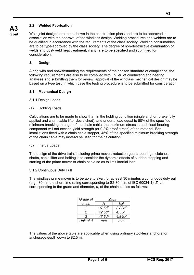
2.2 Welded Fabrication Weld joint designs are to be shown in the construction plans and are to be approved in association with the approval of the windlass design. Welding procedures and welders are to be qualified in accordance with the requirements of the class society. Welding consumables are to be type-approved by the class society. The degree of non-destructive examination of welds and post-weld heat treatment, if any, are to be specified and submitted for consideration. 3. Design Along with and notwithstanding the requirements of the chosen standard of compliance, the following requirements are also to be complied with. In lieu of conducting engineering analyses and submitting them for review, approval of the windlass mechanical design may be based on a type test, in which case the testing procedure is to be submitted for consideration. 3.1 Mechanical Design 3.1.1 Design Loads (a) Holding Loads Calculations are to be made to show that, in the holding condition (single anchor, brake fully applied and chain cable lifter declutched), and under a load equal to 80% of the specified minimum breaking strength of the chain cable, the maximum stress in each load bearing component will not exceed yield strength (or 0.2% proof stress) of the material. For installations fitted with a chain cable stopper, 45% of the specified minimum breaking strength of the chain cable may instead be used for the calculation. (b) Inertia Loads The design of the drive train, including prime mover, reduction gears, bearings, clutches, shafts, cable lifter and bolting is to consider the dynamic effects of sudden stopping and starting of the prime mover or chain cable so as to limit inertial load. 3.1.2 Continuous Duty Pull The windlass prime mover is to be able to exert for at least 30 minutes a continuous duty pull (e.g., 30-minute short time rating corresponding to S2-30 min. of IEC 60034-1), Zcont1, corresponding to the grade and diameter, d, of the chain cables as follows:
Grade of Zcont1
chain N kgf 1 37.5d2 3.82d2 2 42.5d2 4.33d2 3 47.5d2 4.84d2
Unit of d mm mm The values of the above table are applicable when using ordinary stockless anchors for anchorage depth down to 82.5 m.

A3
Page 4 of 6 IACS Req. 2017
A3 (cont)
For anchorage depth deeper than 82.5 m, a continuous duty pull Zcont2 is: Zcont2[N] = Zcont1[N] + (D – 82.5) x 0.27d2 or Zcont2[kgf] = Zcont1[kgf] + (D – 82.5) x 0.0275d2 where D is the anchor depth, in metres. The anchor masses are assumed to be the masses as given in UR A1 and Recommendation 10. Also, the value of Zcont is based on the hoisting of one anchor at a time, and that the effects of buoyancy and hawse pipe efficiency (assumed to be 70%) have been accounted for. In general, stresses in each torque-transmitting component are not to exceed 40% of yield strength (or 0.2% proof stress) of the material under these loading conditions. 3.1.3 Overload Capability The windlass prime mover is to be able to provide the necessary temporary overload capacity for breaking out the anchor. This temporary overload capacity or “short term pull” is to be at least 1.5 times the continuous duty pull applied for at least 2 minutes. The speed in this period may be lower than normal. 3.1.4 Hoisting Speed The mean speed of the chain cable during hoisting of the anchor and cable is to be at least 0.15 m/sec. For testing purposes, the speed is to be measured over two shots of chain cable and initially with at least three shots of chain (82.5 m or 45 fathoms in length) and the anchor submerged and hanging free. 3.1.5 Brake Capacity The capacity of the windlass brake is to be sufficient to stop the anchor and chain cable when paying out the chain cable. Where a chain cable stopper is not fitted, the brake is to produce a torque capable of withstanding a pull equal to 80% of the specified minimum breaking strength of the chain cable without any permanent deformation of strength members and without brake slip. Where a chain cable stopper is fitted, 45% of the breaking strength may instead be applied. 3.1.6 Chain Cable Stopper Chain cable stopper, if fitted, along with its attachments is to be designed to withstand, without any permanent deformation, 80% of the specified minimum breaking strength of the chain cable. 3.1.7 Support Structure For hull supporting structures of windlass and chain cable stoppers, refer to A1.7 of UR A1.

A3
Page 5 of 6 IACS Req. 2017
A3 (cont)
3.2 Hydraulic Systems Hydraulic systems where employed for driving windlasses are to comply with the provisions of the class society. 3.3 Electrical Systems 3.3.1 Electric Motors Electric motors are to meet the requirements of the class society and those rated 100 kW and over are to be certified. Motors exposed to weather are to have enclosures suitable for their location as provided for in the requirements of the class society. Where gears are fitted, they are to meet the requirements of the class society and those rated 100 kW and over are to be certified. 3.3.2 Electrical Circuits Motor branch circuits are to be protected in accordance with the provisions of the class society and cable sizing is to be in accordance with the requirements of the class society. Electrical cables installed in locations subjected to the sea are to be provided with effective mechanical protection. 3.4 Protection of Mechanical Components To protect mechanical parts including component housings, a suitable protection system is to be fitted to limit the speed and torque at the prime mover. Consideration is to be given to a means to contain debris consequent to a severe damage of the prime mover due to over-speed in the event of uncontrolled rendering of the cable, particularly when an axial piston type hydraulic motor forms the prime mover. 3.5 Couplings Windlasses are to be fitted with couplings which are capable of disengaging between the cable lifter and the drive shaft. Hydraulically or electrically operated couplings are to be capable of being disengaged manually. 4. Shop Inspection and Testing Windlasses are to be inspected during fabrication at the manufacturers’ facilities by a Surveyor for conformance with the approved plans. Acceptance tests, as specified in the specified standard of compliance, are to be witnessed by the Surveyor and include the following tests, as a minimum. i) No-load test. The windlass is to be run without load at nominal speed in each direction
for a total of 30 minutes. If the windlass is provided with a gear change, additional run in each direction for 5 minutes at each gear change is required.
ii) Load test. The windlass is to be tested to verify that the continuous duty pull, overload
capacity and hoisting speed as specified in 3.1 can be attained. Where the manufacturing works does not have adequate facilities, these tests, including
the adjustment of the overload protection, can be carried out on board ship. In these cases, functional testing in the manufacturer’s works is to be performed under no-load conditions.
A3
Page 6 of 6 IACS Req. 2017
A3 (cont)
iii) Brake capacity test. The holding power of the brake is to be verified either through testing or by calculation.
5. On-board Tests Each windlass is to be tested under working conditions after installation onboard to demonstrate satisfactory operation. Each unit is to be independently tested for braking, clutch functioning, lowering and hoisting of chain cable and anchor, proper riding of the chain over the cable lifter, proper transit of the chain through the hawse pipe and the chain pipe, and effecting proper stowage of the chain and the anchor. It is to be confirmed that anchors properly seat in the stored position and that chain stoppers function as designed if fitted. The mean hoisting speed, as specified in 3.1.4, is to be measured and verified. The braking capacity is to be tested by intermittently paying out and holding the chain cable by means of the application of the brake. Where the available water depth is insufficient, the proposed test method will be specially considered. 6. Marking Windlass shall be permanently marked with the following information: (a) Nominal size of chain (e.g. 100/3/45 means chain dia./grade/breaking load) (b) Maximum anchorage depth, in metres.
End of Document
Related Documents


