Eleventh USA/Europe Air Traffic Management Research and Development Seminar (ATM2015) Required Surveillance Performance for reduced minimal-pair arrival separations Alan R. Groskreutz Senior Researcher CRIDA A.I.E. Madrid, Spain [email protected] Pablo Muñoz Dominguez Aeronautical Engineering School Technical University of Madrid Madrid, Spain [email protected] Abstract— This paper will investigate and propose preliminary Required Surveillance Performance (RSP) requirements associated to a longitudinal arrival separation of 2.0 NM. Just as new regulations regarding navigation are using Required Navigation Performance (RNP) to disassociate the regulation from a particular type of technology and substitute general performance requirements for any current or future navigation technology, an effort in needed to assign RSP requirements to separation minima. RSP requirements have already been set in Europe for 5NM and 3NM horizontal separations in en-route flight. Currently referred to as the minimal-pair radar separation, non wake turbulence longitudinal arrival separations are set by ICAO at 3 NM (or 2.5 NM if conditions permit). Part of the effort in the SESAR 6.8.1 project is to propose a new, non wake turbulence longitudinal arrival separation of 2.0 NM enabled through Required Surveillance Performance (RSP). The proposed preliminary requirements for a 2NM minimal-pair arrival separation were achieved through the use of the separation model developed within the RESET project. This model uses the current separation minima and their influencing factors to create a separation assurance budget software tool, identifying the various budget components and influencing factors that contribute to the establishment of separation minima. Although several approaches are possible, this formalization takes into account the uncertainties in the position, velocity, and aircraft intent as well as all the factors needed for perception, comprehension and projection of the status of aircraft. This formalization provides the homogeneous means for the technological and procedural assessments in term of contribution to separation minima. In order to ensure the required TLS, a safety assessment needs to be done to analyze the other factors in order to present a complete safety case. However, the preliminary results of this study show that a RSP associated with ADS-B seems to be sufficient for a 2NM minimal-pair arrival separation with current TLS. Keywords-Surveillance; safety; separations; airport; performance I. INTRODUCTION Increasing Europe’s airport capacity is one of the high-level goals of the European SESAR project, which is hoped to also reduce delays both on the ground and in the air. Reducing arrival separation values has long been recognized as one of the key pieces to this capacity puzzle. The way to understand how SM work and how changes could affect them was developed in [1] and [2]. The evolution of separation minima has seemingly been a function of what worked operationally and what was seemed to be acceptably safe from the viewpoint of the approving authorities, but has always referenced the use of a specific technology. We say seemingly, because the basis for the development of the overwhelming majority of separation minima and their influencing factors is not very well documented [8]. However, in order to create separation minima that can adapt to the changing technological and operational environments of the future, their bases not only need to be made explicit, but need to be disengaged from a specific technological implementation. Just as new regulations regarding navigation are using Required Navigation Performance (RNP) to disassociate the regulation from a particular type of technology and substitute general performance requirements for any current or future navigation technology, an effort in needed to assign Required Surveillance Performance (RSP) requirements to separation minima. RSP requirements have already been set in Europe for 5NM and 3NM horizontal separations in en-route flight [3], [4]. Currently referred to as the minimal-pair radar separation, non wake turbulence longitudinal arrival separations are set by ICAO at 3 NM (or 2.5 NM if conditions permit)[6]. Part of the effort in the SESAR 6.8.1 project is to propose a new, non wake turbulence longitudinal arrival separation of 2.0 NM enabled through Required Surveillance Performance (RSP). This paper will investigate and propose preliminary Required Surveillance Performance (RSP) requirements associated to this longitudinal arrival separation of 2.0 NM. II. METHODOLOGY A. Current Separation Minima Standards Currently, most recognized standards can be seen and widely studied in [5], [6] and [1]. As it is the smallest longitudinal arrival separation, a summary of the requirements

Welcome message from author
This document is posted to help you gain knowledge. Please leave a comment to let me know what you think about it! Share it to your friends and learn new things together.
Transcript
Eleventh USA/Europe Air Traffic Management Research and Development Seminar (ATM2015)
Required Surveillance Performance for reduced minimal-pair arrival separations
Alan R. Groskreutz Senior Researcher
CRIDA A.I.E. Madrid, Spain
Pablo Muñoz Dominguez Aeronautical Engineering School Technical University of Madrid
Madrid, Spain [email protected]
Abstract— This paper will investigate and propose preliminary Required Surveillance Performance (RSP) requirements associated to a longitudinal arrival separation of 2.0 NM. Just as new regulations regarding navigation are using Required Navigation Performance (RNP) to disassociate the regulation from a particular type of technology and substitute general performance requirements for any current or future navigation technology, an effort in needed to assign RSP requirements to separation minima. RSP requirements have already been set in Europe for 5NM and 3NM horizontal separations in en-route flight. Currently referred to as the minimal-pair radar separation, non wake turbulence longitudinal arrival separations are set by ICAO at 3 NM (or 2.5 NM if conditions permit). Part of the effort in the SESAR 6.8.1 project is to propose a new, non wake turbulence longitudinal arrival separation of 2.0 NM enabled through Required Surveillance Performance (RSP).
The proposed preliminary requirements for a 2NM minimal-pair arrival separation were achieved through the use of the separation model developed within the RESET project. This model uses the current separation minima and their influencing factors to create a separation assurance budget software tool, identifying the various budget components and influencing factors that contribute to the establishment of separation minima. Although several approaches are possible, this formalization takes into account the uncertainties in the position, velocity, and aircraft intent as well as all the factors needed for perception, comprehension and projection of the status of aircraft. This formalization provides the homogeneous means for the technological and procedural assessments in term of contribution to separation minima.
In order to ensure the required TLS, a safety assessment needs to be done to analyze the other factors in order to present a complete safety case. However, the preliminary results of this study show that a RSP associated with ADS-B seems to be sufficient for a 2NM minimal-pair arrival separation with current TLS.
Keywords-Surveillance; safety; separations; airport; performance
I. INTRODUCTION Increasing Europe’s airport capacity is one of the high-level
goals of the European SESAR project, which is hoped to also
reduce delays both on the ground and in the air. Reducing arrival separation values has long been recognized as one of the key pieces to this capacity puzzle. The way to understand how SM work and how changes could affect them was developed in [1] and [2]. The evolution of separation minima has seemingly been a function of what worked operationally and what was seemed to be acceptably safe from the viewpoint of the approving authorities, but has always referenced the use of a specific technology. We say seemingly, because the basis for the development of the overwhelming majority of separation minima and their influencing factors is not very well documented [8].
However, in order to create separation minima that can adapt to the changing technological and operational environments of the future, their bases not only need to be made explicit, but need to be disengaged from a specific technological implementation. Just as new regulations regarding navigation are using Required Navigation Performance (RNP) to disassociate the regulation from a particular type of technology and substitute general performance requirements for any current or future navigation technology, an effort in needed to assign Required Surveillance Performance (RSP) requirements to separation minima.
RSP requirements have already been set in Europe for 5NM and 3NM horizontal separations in en-route flight [3], [4]. Currently referred to as the minimal-pair radar separation, non wake turbulence longitudinal arrival separations are set by ICAO at 3 NM (or 2.5 NM if conditions permit)[6]. Part of the effort in the SESAR 6.8.1 project is to propose a new, non wake turbulence longitudinal arrival separation of 2.0 NM enabled through Required Surveillance Performance (RSP).
This paper will investigate and propose preliminary Required Surveillance Performance (RSP) requirements associated to this longitudinal arrival separation of 2.0 NM.
II. METHODOLOGY
A. Current Separation Minima Standards Currently, most recognized standards can be seen and
widely studied in [5], [6] and [1]. As it is the smallest longitudinal arrival separation, a summary of the requirements
to support the 2.5 NM separation based on radar is included below.
As stated in [6], the 2.5 NM separation minima may be applied between succeeding aircraft which are established on the same final approach track within 10 NM of the runway end, provided:
• The average runway occupancy time of landing aircraft is proven, by means such as data collection and statistical analysis and methods based on a theoretical model, not to exceed 50 seconds (a calculation of runway occupancy times at Frankfurt Airport can be found in [1], annex 3);
• Braking action is reported as good and runway occupancy are not adversely affected by runway contaminants such as slush, snow or ice;
• A radar system with appropriate azimuth and range resolution and an update periodof 5 seconds or less is used in combination with suitable radar displays;
• The aerodrome controller is able to observe, visually or by means of surface movement radar (SMR) or a surface movement guidance and control system (SMCGS), the runway-in-use and associated exit and entry taxiways;
• Distance-based wake turbulence separation minima, or as may be prescribed by the appropriate ATS authority (e.g. for specific aircraft types, such as B757) , do not apply;
• Aircraft approach speeds are closely monitored by the controller and when necessary adjusted to ensure the separation is not reduced below the minimum;
• Aircraft operators and pilots have been made fully aware of the need to exit the runway in an expeditious manner whenever the reduced separation minimum on final approach is applied; and
• Procedures concerning the application of the reduced minimum are published in AIPs.
It can be seen that there are several parameters that depend on the surveillance sensor type used, especially for primary surveillance radar and secondary surveillance radar, which together make up the typical system used to enable radar coverage on final approach. In fact, as seen in (EUROCONTROL, 1998), duplicated SSR coverage and single PSR is the mandatory minimum system to apply 3 NM separation minima. ADS-B is included in the provisions to apply the 2.5 NM separation minima in ICAO documents, but the associated accuracy, integrity, availability, continuity of service and probability of detection requirements are not listed or referenced in the regulation.
It therefore can be understood that a unification of surveillance requirements, regardless of the type of sensor used, would be advantageous for the rapid approval and implementation of future surveillance systems. It would provide one of the cornerstones to deploy non-traditional systems, such as Multilateration or ADS-B, and promoting
their use while clarifying and simplifying traditional radar-based system performance requirements. These new requirements depend only on the types of separation service being supported (see (Thompson & Flavin, Surveillance Accuracy Requirements in Support of Separation Services, 2006)), i.e. 3/5 NM separation.
B. Setting RSP requirements for 2NM longitudinal approach separations Consequently, international standardization is increasingly
based on Required Total System Performance (RTSP) specifications that are independent of the particular technologies of implementation. The term Required Surveillance Performance (RSP) is the subset of RTSP that is concerned with surveillance requirements. Once a type of air traffic service is specified, it is possible to derive the RSP without reference to the particular technologies used to achieve the requirements.
Validation of this concept in specific cases was achieved by both EUROCONTROL and the FAA as shown in [3], [4], [11] and [12]. The results for both the 5 NM and 3 NM horizontal separation surveillance performance requirements are shown in TABLE VII. (at the end of the document). There are specific values depending on whether the requirements are for mandatory performance (MP) or recommended performance (RP).
While the specification in [3] and [4] are for horizontal separations in the en-route environment, the 2NM separation being proposed is longitudinal and in the approach phase. A separate means to propose and validate RSP specifications for this specific proposed separation was therefore developed.
Taking the RSP table (TABLE I. ) as reference, we can make a linear extrapolation using the 5 and 3 NM requirements in order to set a first approach. Specifications related with this analysis and its results are shown in TABLE I.
TABLE I. RSP EXTRAPOLATION TO 2 NM
2NM MP 2NM RP Units & applicability
Horizontal position. pressure altitude and aircraft identity
3.5 3 Applicable update interval, less than or equal (seconds)
Horizontal position
97 97 Probability of update, greater than or equal (% per flight)
99 Greater than or equal (% global)
Horizontal position
200 140 RMS error, less than or equal (m) global
220 152.5 RMS error, less than or equal (m) per flight
500 Less than or equal to (ft/NM) for climbing/descending flights
Track velocity 4 RMS error, less than or equal to (m/s) for straight line
Track velocity 8 RMS error, less than or equal to (m/s) for turn
Track velocity angle 10 RMS error, less than or equal to
(°) for straight line Track velocity angle 25 RMS error, less than or equal to
(°) for turn
2NM MP 2NM RP Units & applicability
False target reports 2.9E-05
Density of uncorrelated false target reports, number of false target reports per area per update intervals
System 2.5E-05 Continuity (probability of critical failure), less than or equal to (number per hour of operation)
This is understandably rough and requires a means to check the values to determine how representative they are.
C. The RESET Separation Assurance Budget Model The RESET Model, developed in the late 2000s within the
RESET project, has been validated as a prototyping model for testing specifications for new separations. The RESET Model is not a collision risk model, but a simplified theoretical model based on the studies developed by Reynolds and Hansman[14], the Rockman model[15], and the Ennis and Zhao aircraft protected zones[16]. This model can be used for determining the impact on Separation Minima of new operational concepts or enablers, like those proposed by SESAR.
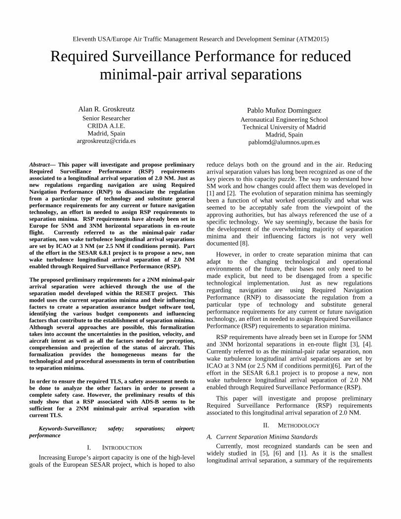
The RESET model represents an artificial region around a given aircraft that no other aircraft should penetrate in order to define the minimum separation requirements. This artificial region contains several envelopes, or budgets, whose composition has been analyzed in terms of representative factors, their influence, and the effective ways to reduce the sizes of these budgets. The following components build up to the separation minimum as drawn in Figure 1:
Forbidden Zone
Collision Cross Section
Surveillance Uncertainty
Aircraft Surveillance and Navigation Performance
Ground/Satellite Systems Surveillance
Intervention Buffer
Detection, Reaction, Communication Time
Aircraft Performance
Human Performance (ATCo and Pilot)
Environment
Communication Capability
ATC Rules and Situation Complexity
Wake Turbulence Zone
The model is based on a reference trajectory for each of the aircraft, flying in collision headings. The X and Y axis represent East-North axis, with meters as the longitudinal unit. To compute the separation needed to assure a safe flight, the fact that the aircraft does not follow the theoretical trajectory, because the pilot does not know the actual position and the aircraft does not respond perfectly to the pilot commands has to be taken into account.
Figure 1: Common Separation Minimum breakdown structure (RESET)
Extended information on the structure of the model can be found on the RESET website (http://www.reset.aena.es) and particularly in [13]. The detailed separation component breakdown, including associated influential factors, can be found in [17]. However, a brief description of the surveillance layer has been included here to have a clear picture of the model’s basis in the area that will be explored.
The surveillance uncertainty corresponds to the uncertainty related to the positioning of the aircraft as seen by the ATCo and includes:
• The exact positioning of the aircraft at each positioning report.
• The additional uncertainty due to missing information between 2 discrete positioning reports.
• The possibility of system failure in the reporting of the aircraft positioning (missing reports). This component is also linked to the communication factors, especially in case of procedural control, which is also a back-up process in case of a radar failure.
• The display accuracy on the controller screen.
The RSP concept, defined as "the set of system performance parameters that are required for a surveillance system to support a surveillance application", is also covered by this layer. This includes the following set of system performance parameters: accuracy, availability, integrity, latency and refresh rate. Factors related to the ground equipment and procedures and also on-board should be taken into account within this buffer; thus, this buffer will be presented in two parts: Aircraft Surveillance and Navigation Performance, and Ground Surveillance.
The following A/C Surveillance and Navigation Performance factors were selected as the most representative for this buffer:
• Sensor accuracy
• Basic update rate
• Effects of more accurate navigation
• Required Navigation Performance (RNP)
• Typical and non-typical performance
• Time-keeping accuracy
Sensor accuracy is understood as the accuracy of the entire system, from the measurement of the raw data to the information display. Three specific accuracy sub-models were required:
Model of Trajectory Deviations. In several cases, the conversion from the Cartesian position error to same track and cross track error is useful. The expressions used were:
𝑎 = (𝑥 − 𝑥𝑛) · 𝑠𝑠𝑠Ψ n + (𝑦 − 𝑦𝑛) · 𝑐𝑐𝑠Ψ n; (1) c=(𝑥 − 𝑥𝑛) · 𝑐𝑐𝑠Ψ n + (𝑦 − 𝑦𝑛) · 𝑠𝑠𝑠Ψ n (2)
Where a and c are the same track and cross track errors and n is the nominal magnitude. X and y are the aircraft position in the East/North direction and Ψ is the heading angle.
Model of RNP. It is defined as a parameter describing lateral deviations from assigned or selected track as well as along track position fixing accuracy on the basis of an appropriate containment level. The RNP type defines the total system error (TSE) allowed in the horizontal dimension when operating within a defined airspace or on a designed route. The Total System Error (TSE) for the longitudinal dimension is the combination of the navigation system error, RNAV error computation, and display error; while for the lateral dimension the TSE includes all the above errors plus the flight technical error (FTE). That means that the RNP value is the size in nautical miles of the space around the estimated position of the aircraft where the aircraft really is, with a defined percentage of probability.
Height model. The model defined in a document referenced by (AENA, 2008) analyses the data collected in the European Vertical Data Collection and gives a probability distribution for the height keeping errors, and the parameter values that fit to the observed data.
As it can be seen, aircraft surveillance and navigation performance are important for procedural control and en-route separation but not a factor for final approach longitudinal separations.
The following Ground Surveillance (including Satellite Systems) factors were selected as the most representatives for this buffer:
• Accuracy of measured position after processing
• Update rate
• Display accuracy (error)
• ADS sensor accuracy
• ADS basic update rate
• Accuracy
• Integrity
• Automation-induced errors
• False positives
• Missed events
The primary function of a surveillance system is to provide an accurate estimate of the position and identity of aircraft. A surveillance system may be characterized in terms of the following parameters:
• Coverage volume
• Accuracy
• Integrity
• Update rate
• Reliability
• Availability
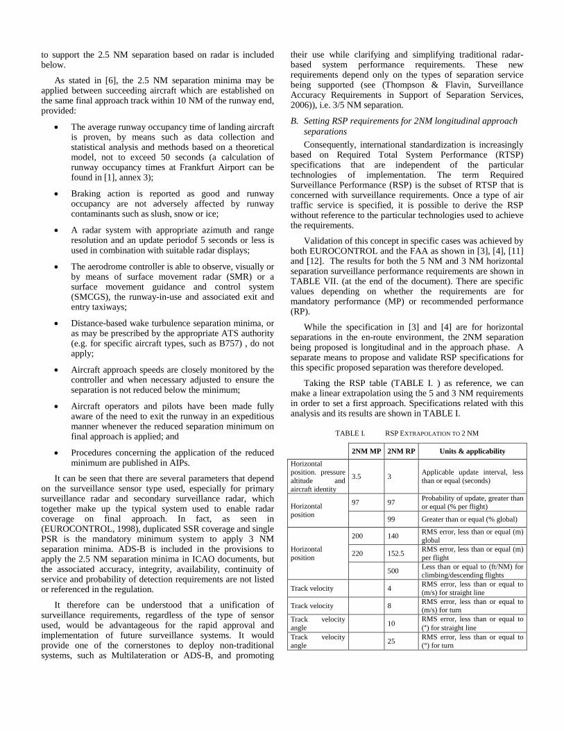
The separation minima that should be maintained between the aircraft is a combination of all of these contributions. The way each of the factors affects the separation minima is complex, as they form a two loop control system (as shown in the figure below). While the pilot tries to control the aircraft using the measures from the on-board sensors, the ATCo controls the aircraft (via the pilot) using the measures from the surveillance sensors. That means that the pilot control errors and the on-board sensor errors can be corrected with the ATCo commands, while the pilot can be unable of follow the ATCo commands if the on-board information error or the control error are high.
Figure 2: System block description
As a first approximation, the following factors are added:
• The distance derived from the Pilot and ATCo intervention time.
• The distance needed to perform successful collision avoidance.
• The RNP or the ATCo sensor error, depending on who is responsible for the control.
The addition of these factors defines the distance needed by the system to perform the full process of avoiding a conflict.
The model is implemented as a MATLAB tool which contains different modules that correspond to the different budget envelopes .
Pilot(Pilot
Intervention)
Aircraft(Forbidden Zone)
On board sensor
ATCo(ATCo
Intervention)
Ground Surveillance
(Ground Surveillance)
Pilot coefficient
•Time default•Sample time•Angle search•Number of velocity intervals•Wind velocities
•Sensor type•Sensor position•Surveillance coefficient
RNP flagRNP coefficientRNP percentile
Number of additional time
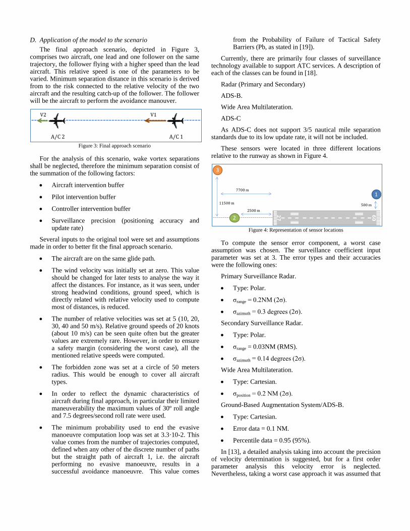
D. Application of the model to the scenario The final approach scenario, depicted in Figure 3,
comprises two aircraft, one lead and one follower on the same trajectory, the follower flying with a higher speed than the lead aircraft. This relative speed is one of the parameters to be varied. Minimum separation distance in this scenario is derived from to the risk connected to the relative velocity of the two aircraft and the resulting catch-up of the follower. The follower will be the aircraft to perform the avoidance manouver.
Figure 3: Final approach scenario
For the analysis of this scenario, wake vortex separations
shall be neglected, therefore the minimum separation consist of the summation of the following factors:
• Aircraft intervention buffer
• Pilot intervention buffer
• Controller intervention buffer
• Surveillance precision (positioning accuracy and update rate)
Several inputs to the original tool were set and assumptions made in order to better fit the final approach scenario.
• The aircraft are on the same glide path.
• The wind velocity was initially set at zero. This value should be changed for later tests to analyse the way it affect the distances. For instance, as it was seen, under strong headwind conditions, ground speed, which is directly related with relative velocity used to compute most of distances, is reduced.
• The number of relative velocities was set at 5 (10, 20, 30, 40 and 50 m/s). Relative ground speeds of 20 knots (about 10 m/s) can be seen quite often but the greater values are extremely rare. However, in order to ensure a safety margin (considering the worst case), all the mentioned relative speeds were computed.
• The forbidden zone was set at a circle of 50 meters radius. This would be enough to cover all aircraft types.
• In order to reflect the dynamic characteristics of aircraft during final approach, in particular their limited maneuverability the maximum values of 30º roll angle and 7.5 degrees/second roll rate were used.
• The minimum probability used to end the evasive manoeuvre computation loop was set at 3.3·10-2. This value comes from the number of trajectories computed, defined when any other of the discrete number of paths but the straight path of aircraft 1, i.e. the aircraft performing no evasive manoeuvre, results in a successful avoidance manoeuvre. This value comes
from the Probability of Failure of Tactical Safety Barriers (Pb, as stated in [19]).
Currently, there are primarily four classes of surveillance technology available to support ATC services. A description of each of the classes can be found in [18].
Radar (Primary and Secondary)
ADS-B.
Wide Area Multilateration.
ADS-C
As ADS-C does not support 3/5 nautical mile separation standards due to its low update rate, it will not be included.
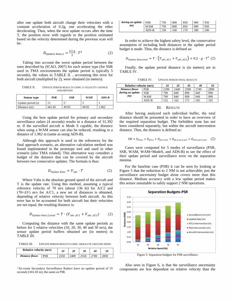
These sensors were located in three different locations relative to the runway as shown in Figure 4.
Figure 4: Representation of sensor locations
To compute the sensor error component, a worst case
assumption was chosen. The surveillance coefficient input parameter was set at 3. The error types and their accuracies were the following ones:
Primary Surveillance Radar.
• Type: Polar.
• σrange = 0.2NM (2σ).
• σazimuth = 0.3 degrees (2σ).
Secondary Surveillance Radar.
• Type: Polar.
• σrange = 0.03NM (RMS).
• σazimuth = 0.14 degrees (2σ).
Wide Area Multilateration.
• Type: Cartesian.
• σposition = 0.2 NM (2σ).
Ground-Based Augmentation System/ADS-B.
• Type: Cartesian.
• Error data = 0.1 NM.
• Percentile data = 0.95 (95%).
In [13], a detailed analysis taking into account the precision of velocity determination is suggested, but for a first order parameter analysis this velocity error is neglected. Nevertheless, taking a worst case approach it was assumed that
A/C 2 A/C 1
V2 V1
1
2
3
500 m2500 m
11500 m
7700 m
after one update both aircraft change their velocities with a constant acceleration of 0.2g, one accelerating the other decelerating. Thus, when the next update occurs after the time T, the position error with regards to the position estimated based on the velocity determined during the previous scan will be:
𝐷𝑈𝑈𝑈𝑈𝑈𝑈 𝑅𝑈𝑈𝑈,1 = 0.2·𝑔2
· 𝑇2 (2)
Taking into account the worst update period between the ones described by (ICAO, 2007) for each sensor type (for SSR used in TMA environments the update period is typically 5 seconds), the values in TABLE II. , accounting this error for both aircraft (multiplied by 2), were obtained (in meters):
TABLE II. UPDATE PERIOD RESULTS USING A VELOCITY CHANGE ASSUMPTION
Sensor type PSR SSR WAM ADS-B
Update period (s) 15 51 5 1 Distance (m) 441.45 49.05 49.05 1.962
Using the best update period for primary and secondary surveillance radars (4 seconds) results in a distance of 31.392 m. If the surveilled aircraft is Mode S capable, the distance when using a WAM sensor can also be reduced, resulting in a distance of 1.962 m (same as using ADS-B).
Although this approach is used in the references for the final approach scenario, an alternative calculation method was found implemented in the prototype tool and used in other scenario (also TMA related). This alternative way considers a budget of the distance that can be covered by the aircraft between two consecutive updates. The formula is thus:
𝐷𝑈𝑈𝑈𝑎𝑈𝑈 𝑅𝑎𝑈𝑈 = 𝑉𝑎𝑎𝑠 · 𝑇 (2)
Where Vabs is the absolute ground speed of the aircraft and T is the update rate. Using this method, assuming a typical reference velocity of 70 m/s (about 136 kt) for A/C2 and (70+ΔV) m/s for A/C1, a new set of distances is obtained, depending of relative velocity between both aircraft. As this error has to be accounted for both aircraft but their velocities are not equal, the resulting distance is:
𝐷𝑈𝑈𝑈𝑎𝑈𝑈 𝑅𝑎𝑈𝑈,2,𝑈𝑐𝑈𝑎𝑡 = 𝑇 · (𝑉𝑎𝑎𝑠 ,𝐴𝐴1 + 𝑉𝑎𝑎𝑠 ,𝐴𝐴2) (2)
Computing the distance with the same update periods as before for 5 relative velocities (10, 20, 30, 40 and 50 m/s), the sensor update period buffers obtained are (in meters) in TABLE III.
TABLE III. UPDATE PERIOD RESULTS USING ABSOLUTE GROUND SPEED
Relative velocity (m/s) 10 20 30 40 50
Distance flown PSR 2250 2400 2550 2700 2850
1 En-route Secondary Surveillance Radars have an update period of 15 seconds (441.45 m), the same as PSR.
during an update (m)
SSR 750 800 850 900 950 WAM 750 800 850 900 950 ADS-B 150 160 170 180 190
In order to achieve the highest safety level, the conservative assumption of including both distances in the update period budget is made. Thus, the distance is defined as:
𝐷𝑈𝑈𝑈𝑎𝑈𝑈 𝑅𝑎𝑈𝑈,𝑈𝑐𝑈𝑎𝑡 = 𝑇 · �𝑉𝑎𝑎𝑠 ,𝐴𝐴1 + 𝑉𝑎𝑎𝑠 ,𝐴𝐴2� + 0.2 · 𝑔 · 𝑇2 (2)
Finally, the update period distance is (in meters) are in TABLE IV.
TABLE IV. UPDATE PERIOD FINAL RESULTS
Relative velocity (m/s) 10 20 30 40 50 Distance flown
during an update (m)
PSR 2299 2449 2599 2749 2899 SSR 799 849 899 949 999 WAM 799 849 899 949 999 ADS-B 152 162 172 182 192
III. RESULTS After having analyzed each individual buffer, the total
distance should be presented in order to have an overview of the required separation budget. The forbidden zone has not been considered separately, but within the aircraft intervention distance. Thus, the distance is defined as:
𝑆𝑆 = 𝐷𝑃𝑃𝑃𝑃𝑈 + 𝐷𝐴𝐴𝐴𝑃 + 𝐷𝐴𝑃𝐴𝐴𝐴𝑈𝐴𝑈 + 𝐷𝑆𝑆,2 𝑈𝑃𝐴𝐴𝐴𝑈𝐴𝑈 + 𝐷𝑈𝑅,2 𝑈𝑃𝐴𝐴𝐴𝑈𝐴𝑈 (2)
Cases were computed for 5 modes of surveillance (PSR, SSR, WAM, WAM+ModeS, and ADS-B) to see the effect of their update period and surveillance error on the separation minima.
For the baseline case (PSR) it can be seen by looking at Figure 5 that the reduction to 2 NM is not achievable; just the surveillance uncertainty budget alone covers more than this distance. Medium accuracy with a low update period makes this sensor unsuitable to safely support 2 NM operations.
Figure 5: Separation budgets for PSR surveillance
Also seen in Figure 6, is that the surveillance uncertainty components are less dependent on relative velocity than the
0,00
0,50
1,00
1,50
2,00
2,50
3,00
3,50
4,00
4,50
19 39 58 78 97
Dist
ance
(NM
)
Relative Speed (kt)
Separation Budgets-PSR
Surveillance error (m)
Update Rate (m)
ATCo Intervention (m)
Pilot Intervention (m)
Aircraft Intervention (m)
other components, i.e. make up a larger fraction of the total separation minimum for lower closure rates (as shown in the next figure). It can also be seen that the pilot and controller intervention buffers are decreasing quickly for decreasing closure rate, whereas the aircraft intervention buffer shows a slower decline.
Figure 6: Separation budgets for SSR surveillance
In the SSR case shown in Figure 6, results show that a
reduction from 2.5 NM to 2 NM may be possible assuming some requirements, listed in the conclusions, are taken into account.
Looking at the makeup of the separation minima components in Figure 7, it can be seen that for high relative velocities, the largest fraction are the intervention buffers. However, for the more likely lower relative velocity scenarios, the largest fraction is the surveillance uncertainty (Surveillance error plus Update Rate). This gives evidence that reducing the surveillance uncertainty is a good way to maintain safety while reducing separation minima.
Figure 7: Relative SM components (Baseline case)
The Multilateration results in Figure 8 show a good update period but a bad nominal surveillance error. They are better than the PSR results, but worse than the baseline case.
Figure 8: Separation budgets for WAM surveillance
The update period can be improved when used by Mode S
aircraft (update period of typically 1 second). This can be seen in Figure 9 where the reduced update period improve the results, making the reduced SM feasible when the relative velocity is up to almost 30 m/s (about 58 knots). However, accuracy should be improved in order to make the multilateration a highly suitable sensor to support the reduced SM.
Figure 9: Separation budgets for WAM+ModeS surveillance
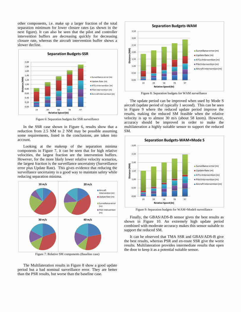
Finally, the GBAS/ADS-B sensor gives the best results as
shown in Figure 10. An extremely high update period combined with moderate accuracy makes this sensor suitable to support the reduced SM.
It can be observed that TMA SSR and GBAS/ADS-B give the best results, whereas PSR and en-route SSR give the worst results. Multilateration provides intermediate results that open the door to keep it as a potential suitable sensor.
0,00
0,20
0,40
0,60
0,80
1,00
1,20
1,40
1,60
1,80
2,00
19 39 58 78 97
Dist
ance
(NM
)
Relative Speed (kt)
Separation Budgets-SSR
Surveillance error (m)
Update Rate (m)
ATCo Intervention (m)
Pilot Intervention (m)
Aircraft Intervention (m)
10 m/s 20 m/s
Aircraft Intervention (m)
Update Rate (m)
Surveillance error (m)
Pilot Intervention (m)
30 m/s 40 m/s
0,00
0,50
1,00
1,50
2,00
2,50
3,00
3,50
19 39 58 78 97
Dist
ance
(NM
)
Relative Speed (kt)
Separation Budgets-WAM
Surveillance error (m)
Update Rate (m)
ATCo Intervention (m)
Pilot Intervention (m)
Aircraft Intervention (m)
0,00
0,50
1,00
1,50
2,00
2,50
3,00
19 39 58 78 97
Dist
ance
(NM
)
Relative Speed (kt)
Separation Budgets-WAM+Mode S
Surveillance error (m)
Update Rate (m)
ATCo Intervention (m)
Pilot Intervention (m)
Aircraft Intervention (m)
Figure 10: Separation budgets for ADS-B surveillance
The ADS-B and TMA SSR sensors provide the best
position accuracies, whereas the ADS-B and the improved (Mode S) Multilateration systems provide the best update period (1 second). WAM accuracy needs to be enhanced but it seems that ADS-B accuracy is good enough (95% less than 0.1 NM).
Setting a first surveillance error at 567 m (ADS-B), the distance available to be covered by the update period is shown in the table below. Solving the following formula (taking the same assumptions than in the previous chapter), the maximum update period can be obtained and are shown in TABLE V.
𝐷𝑈𝑈𝑈𝑎𝑈𝑈 𝑅𝑎𝑈𝑈 = 𝑇 · (𝑉𝑎𝑎𝑠 ,𝐴𝐴1 + 𝑉𝑎𝑎𝑠 ,𝐴𝐴2) + 0.2 · 𝑔 · 𝑇2 = 𝑇 · (140 + ∆𝑉) +0.2 · 𝑔 · 𝑇2 (6)
Figure 11: Sensor type SM comparison
TABLE V. MAXIMUM UPDATE PERIOD USING ADS-B ACCURACY
Relative speed (m/s) 10 20 30 40 50
Maximum Update period (m) 2690 2263 1826 1389 952
Maximum Update period (s) 14,99 12,29 9,66 7,16 4,78
It can be observed that an update period of 5 seconds should be enough in this case.
If the surveillance error is set at 2222 m (PSR and WAM), using the same equation and assumptions, the results areas shown in TABLE VI.
TABLE VI. MAXIMUM UPDATE PERIOD USING PSR ACCURACY
Relative speed (m/s) 10 20 30 40 50 Maximum Update Period (m) 1034,6 607,6 170,6 NP NP Maximum Update Period (s) 6,37 3,64 0,99 NP NP
It is not possible to obtain the maximum update period for relative velocities of 40 and 50 m/s because the whole surveillance uncertainty distance is covered by the surveillance error. However, an update period of 1 second may be considered if a condition is imposed: the relative velocity of each aircraft pair performing their final approach must not be greater than 30 m/s (about 58 kt).
Using the baseline case surveillance error (333.36 m), the maximum update periodresults in values of the same order as the first case (ADS-B accuracy) values (≈5 s).
IV. CONCLUSIONS The applicable update interval of 3.5 (MP) and 3 (RP)
seconds obtained from the extrapolation are quite similar to the RESET model outcome, and are between the interval defined (1-5 seconds depending on the surveillance sensor type used).
The horizontal position RMS error. obtained from the extrapolation is about 200 m for mandatory performance and about 140 for recommended performance. An RMS error of 0.1 NM is about 185 m, which is below the mandatory performance value and is the typical accuracy of most of the surveillance systems used in the computation (2σ errors were used where possible). It seems to be a reasonable value when combined with a high update rate.
The extrapolated RMS error is less than or equal to 4 m/s. During the SM computations, an acceleration of 0.2·g was considered between two consecutive updates as a worst case assumption due to the ignorance of velocity error. It results in a velocity increase of 0.2·g·T (where T is the update rate). On the one hand, the maximum update periodof 5 seconds makes the velocity grow up by g m/s (9.81 m/s). On the other hand, the minimum update periodof 1 second makes it grow up by 1.962 m/s. The intermediate value of 3 seconds results in 5.886 m.
It is assumed that ADS-B will eventually become the preferred surveillance technology worldwide, although this will take time. Changes to ICAO documents are about to be published recognising ADS-B use to support 5 nautical mile separation standards whereas proposals to allow 3 nautical mile separation standards using ADS-B are in process. Results from this analysis indicate that RSP values associated with ADS-B are in line with a safe application of a 2NM arrival minimal-pair separation.
0,00
0,20
0,40
0,60
0,80
1,00
1,20
1,40
1,60
1,80
19 39 58 78 97
Dist
ance
(NM
)
Relative Speed (kt)
Separation Budgets-ADS-B
Surveillance error (m)
Update Rate (m)
ATCo Intervention (m)
Pilot Intervention (m)
Aircraft Intervention (m)
0,5
1
1,5
2
2,5
3
3,5
4
10 20 30 40 50
SM (N
M)
Relative velocity (m/s)
Sensor type SM comparison
SSR baselineEn-route SSRPSRWAMWAM + Mode SGBAS/ADS-B
However, ADS-B has a short term critical issue: it requires ADS-B avionics including GPS or similar in participating aircraft. Whilst many airliner manufacturers produce aircraft with ADS-B avionics a large legacy fleet remains to be unequipped. The situation is different in different regions of the world and in different aviation segments. Additional information of ADS-B equipage can be found in [18].The benefits of ADS-B makes it the desired surveillance system to achieve a safe reduced SM in the future. In the long term, once aircraft are equipped, ADS-B may also allow air-air surveillance benefits, such as collision alert systems, which could reduce the ATCo intervention buffer and perhaps the workload for controllers.
Multilateration could also be used, but its accuracy should be improved by carefully setting the number and geometry of ground stations. Mode S equipage and some kind of relative velocity alert are required (the limit was set at 30 m/s – 58 kt). It seems to be a reasonable surveillance system in some locations, when existing infrastructure is available.
As the RESET separation minima model is not a CRM per se, safety statements are not for use in a final safety analysis, just recommendations and approximations. What it has shown is that it is a useful tool to determine further courses of action, especially when selecting amongst various technologies to be further investigated.
REFERENCES [1] EUROCONTROL, “Guidelines for the Application of the ECAC Radar
Separation Minima,” 1998.
[2] ICAO, “Document 9689: Manual on Airspace Planning Methodology for the determination of Separation Minima,” First Edition-1998.
[3] EUROCONTROL, “EUROCONTROL Specification for ATM Surveillance System Performance (Volume 1),” 2012.
[4] EUROCONTROL, “EUROCONTROL Specification for ATM Surveillance System Performance (Volume 2 Appendices),” 2012.
[5] D. Mosquera-Benitez, A. R. Groskreutz and L. Fucke, “Separation Minima Model: How Changes in Contributing Factors Could Affect Current Standards,” 2009.
[6] ICAO, “Document 4444 PANS-ATM,” 2007.
[7] S. D. Thompson, “Terminal Area Separation Standards: Historical Development, Current Standards and Processes for Change,” 1997.
[8] D. Mosquera Benitez, “RESET Separation Minima List WP3. Separation Foundations, Budget and Contributing Factors,” 2008.
[9] ICAO, “A Unified Framework for Collision Risk Modelling in Support of the Manual on Airspace Planning Methodology for the Determination of Separation Minima (Doc 9689),” 2009.
[10] S. D. Thompson and J. M. Flavin, “Surveillance Accuracy Requirements in Support of Separation Services,” 2006.
[11] S. D. Thompson, J. W. Andrews, G. S. Harris and K. A. Sinclair, “Required Surveillance Performance Accuracy to Support 3-Mile and 5-Mile Separation in the National Airspace System,” 2006.
[12] J. W. Andrews and S. D. Thompson, “Validation of Required Surveillance Performance (RSP) Accuracy,” 2007.
[13] AENA, “RESET D3.2 Separation Assurance Budget Model,” 2008.
[14] Reynolds T.G., Hansman R.J., Analysis of Aircraft Separation Minima Using a Surveillance State Vector Approach, MIT, 2001
[15] Rockman, M. J., A Review of the Current Radar Separation Minima and
Some Thoughts on Reducing Them, MITRE Working Note # 94W000099, July 29, 1994
[16] L. E. Ennis and Y. J. Zhao, “A formal approach to the analysis of aircraft protected zone,” 2004
[17] D. Mosquera Benitez and L. Fucke, “RESET D3.1 Separation Budget Components,” 2008.
[18] ICAO, “Guidance Material on Comparison of Surveillance Technologies (GMST),” 2007.
[19] E. J. García González, “Development of a 3-Dimensional Mathematical CRM based on Recorded Trajectories to Estimate the Safety Level in High Density En-Route Airspaces,” 2013.
AUTHORS BIOGRAPHY Alan R. Groskreutz received a Bachelor of Science degree in Aeronautical Engineering from Purdue University, West Lafayette, IN, USA in 1990, majoring in air transportation. In 2001 he received a Master of Business Administration from the University of Houston, Houston Texas, USA. Growing tired of the midwest winters, he moved to Houston, Texas, USA where he worked for 12 years at the Johnson Space Center as an astronaut instructor and NASA flight controller. Seeking even warmer climates, he moved to Madrid, Spain where he is currently working at CRIDA (Centro de Referencia de Investigacion y Desarrollo de ATM) as the leader of the safety group and project manager for SESAR project 6.2 along with other SESAR activities. Pablo Muñoz Dominguez received a degree in Aeronautical Engineering (which is equivalent to a Master of Science level) from the Polytechnic University of Madrid, Spain in 2014, majoring in airports. He worked for thirteen months at CRIDA (Centro de Referencia de Investigacion y Desarrollo de ATM) as trainee researcher, while developing his Master Thesis..
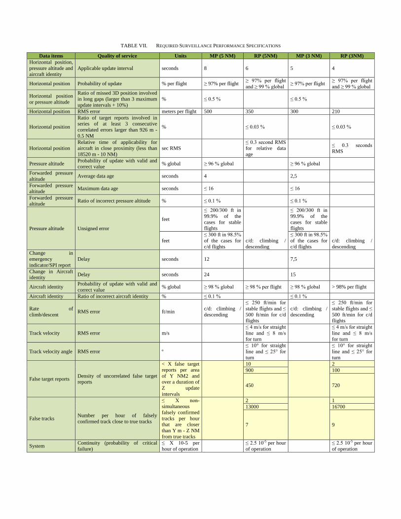
TABLE VII. REQUIRED SURVEILLANCE PERFORMANCE SPECIFICATIONS
Data items Quality of service Units MP (5 NM) RP (5NM) MP (3 NM) RP (3NM) Horizontal position, pressure altitude and aircraft identity
Applicable update interval seconds 8 6 5 4
Horizontal position Probability of update % per flight ≥ 97% per flight ≥ 97% per flight and ≥ 99 % global ≥ 97% per flight ≥ 97% per flight
and ≥ 99 % global
Horizontal position or pressure altitude
Ratio of missed 3D position involved in long gaps (larger than 3 maximum update intervals + 10%)
% ≤ 0.5 % ≤ 0.5 %
Horizontal position RMS error meters per flight 500 350 300 210
Horizontal position
Ratio of target reports involved in series of at least 3 consecutive correlated errors larger than 926 m - 0.5 NM
% ≤ 0.03 % ≤ 0.03 %
Horizontal position Relative time of applicability for aircraft in close proximity (less than 18520 m - 10 NM)
sec RMS ≤ 0.3 second RMS for relative data age
≤ 0.3 seconds RMS
Pressure altitude Probability of update with valid and correct value % global ≥ 96 % global ≥ 96 % global
Forwarded pressure altitude Average data age seconds 4 2,5
Forwarded pressure altitude Maximum data age seconds ≤ 16 ≤ 16
Forwarded pressure altitude Ratio of incorrect pressure altitude % ≤ 0.1 % ≤ 0.1 %
Pressure altitude Unsigned error
feet
≤ 200/300 ft in 99.9% of the cases for stable flights
c/d: climbing / descending
≤ 200/300 ft in 99.9% of the cases for stable flights
c/d: climbing / descending
feet ≤ 300 ft in 98.5% of the cases for c/d flights
≤ 300 ft in 98.5% of the cases for c/d flights
Change in emergency indicator/SPI report
Delay seconds 12 7,5
Change in Aircraft identity Delay seconds 24 15
Aircraft identity Probability of update with valid and correct value % global ≥ 98 % global ≥ 98 % per flight ≥ 98 % global > 98% per flight
Aircraft identity Ratio of incorrect aircraft identity % ≤ 0.1 % ≤ 0.1 %
Rate of climb/descent RMS error ft/min c/d: climbing /
descending
≤ 250 ft/min for stable flights and ≤ 500 ft/min for c/d flights
c/d: climbing / descending
≤ 250 ft/min for stable flights and ≤ 500 ft/min for c/d flights
Track velocity RMS error m/s ≤ 4 m/s for straight line and ≤ 8 m/s for turn
≤ 4 m/s for straight line and ≤ 8 m/s for turn
Track velocity angle RMS error º ≤ 10° for straight line and ≤ 25° for turn
≤ 10° for straight line and ≤ 25° for turn
False target reports Density of uncorrelated false target reports
< X false target reports per area of Y NM2 and over a duration of Z update intervals
10
2 900 100
450 720
False tracks Number per hour of falsely confirmed track close to true tracks
≤ X non-simultaneous falsely confirmed tracks per hour that are closer than Y m - Z NM from true tracks
2
1 13000 16700
7 9
System Continuity (probability of critical failure)
≤ X 10-5 per hour of operation ≤ 2.5 10-5 per hour
of operation ≤ 2.5 10-5 per hour of operation
Related Documents

![The Phoneme - Phoneme vs. Allophone - Minimal pair ... vs... · Classification system for categorizing the ... [p ] - 3 allophones of ... phonetic environments in which a sound](https://static.cupdf.com/doc/110x72/5aadacdd7f8b9a8d678e81f4/the-phoneme-phoneme-vs-allophone-minimal-pair-vsclassification-system.jpg)