1 KENYA ELECTRICITY GENERATING COMPANY LIMITED KGN-GT-012-2017 Tender for Re-location of One GE Frame 6 Gas Turbine Plant from Embakasi in Nairobi to Muhoroni near Kisumu. Scope :( Dismantling, Transportation, Supply of Goods, Civil Works, Assembly and Commissioning) (OPEN INTERNATIONAL TENDER) Kenya Electricity Generating Company Limited 10 th Floor, KenGen Pension Plaza 2, P.O. Box 47936-00100 NAIROBI, KENYA . Website: www.kengen.co.ke July, 2017

Welcome message from author
This document is posted to help you gain knowledge. Please leave a comment to let me know what you think about it! Share it to your friends and learn new things together.
Transcript

1
KENYA ELECTRICITY GENERATING COMPANY LIMITED
KGN-GT-012-2017
Tender for Re-location of One GE Frame 6 Gas Turbine
Plant from Embakasi in Nairobi to Muhoroni near
Kisumu.
Scope :( Dismantling, Transportation, Supply of Goods, Civil
Works, Assembly and Commissioning) (OPEN INTERNATIONAL TENDER)
Kenya Electricity Generating
Company Limited
10th Floor, KenGen Pension
Plaza 2,
P.O. Box 47936-00100 NAIROBI, KENYA .
Website: www.kengen.co.ke
July, 2017

2
TABLE OF CONTENTS
SECTION I: INVITATION FOR TENDERS (IFT)............................................................... 3
SECTION II: INTRODUCTION ............................................................................................... 5
A. INSTRUCTION TO TENDERERS ........................................................................... 5
B. TENDERING DOCUMENTS .................................................................................... 8
C. PREPARATION OF TENDERS .............................................................................. 10
D. SUBMISSION OF TENDERS .................................................................................. 16
E. OPENING AND EVALUATION OF TENDERS ................................................... 18
F. AWARD OF CONTRACT ........................................................................................ 24
SECTION III:TENDER DATA SHEET (TDS) ....................................................................... 28
SECTION IV:CONDITIONS OF CONTRACT ..................................................................... 39
SECTION V:DRAWINGS…………….…………………………………………………...55
SECTIONVI: SCHEDULE OF REQUIREMENTS AND TECHNICAL
SPECIFICATIONS .................................................................................................... 56
SECTION VII TENDER FORM ............................................................................................. 92
SECTION VIII TENDER SECURITY FORM ....................................................................... 94
SECTION IX CONTRACT FORM .......................................................................................... 97
SECTION X PERFORMANCE SECURITY FORM .......................................................... 976
SECTION XI MANDATORY CONFIDENTIAL BUSINESS QUESTIONNAIRE…977
SECTION XII QUALIFICATION INFORMATION …………………………………102
SECTION XIII TENDER QUESTIONNAIRE………………………………………...106

3
SECTION I: INVITATION FOR TENDERS (IFT)
The Company invites sealed tenders from eligible candidates for Re-location of One GE
Frame 6 Gas Turbine Plant from Embakasi in Nairobi to Muhoroni near Kisumu
(approximately 310 km).
The scope of work will involve Dismantling, Transportation, Supply of Goods, Civil Works,
Assembly and Commissioning of the plant whose specifications are detailed in the tender
documents.
Interested eligible candidates may obtain further information from, and inspect the Tender
Documents at the office of:
Supply Chain Director
Tel: (254)(020)3666000 Email: [email protected]
Cc: [email protected]; [email protected];
A complete set of Tender Documents may be obtained by interested tenderers upon payment
of a non-refundable fee of KShs.1, 000.00 (One Thousand Kenyan Shillings) and can also
be viewed and downloaded from the Company’s website http://www.kengen.co.ke. who
download the document are not required to pay any charges but are advised to immediately
submit their details to [email protected] to facilitate subsequent additional information
if any.
Tenderers are also advised to be keen on the information under the appendix to
Instructions to Tenderers and the Conditions of the Contract. Tenders must be accompanied by a security of KShs.2,000,000.00 (Two Million Kenyan
Shillings) or equivalent in USD as specified in the tender documents, and must be
submitted in a plain sealed envelope marked Tender for Re-location of One GE Frame 6
Gas Turbine Plant from Embakasi in Nairobi to Muhoroni near Kisumu
(approximately 310 km) and delivered to:
Company Secretary &Legal Affairs Director
Kenya Electricity Generating Company Limited
10th Floor, KenGen Pension Plaza 2,
P OBox 47936-00100
NAIROBI, KENYA.
Or be deposited in the tender box situated in the Supply Chain Office on the Ground Floor,
Stima Plaza, on or before: 3rd August 2017at 10.00a.m.
Site Visit: There shall be Mandatory Site Visit at KenGen’s Embakasi GT as per details below:-
Location: Embakasi GT- Nairobi near KPLC Substation
Day: Tuesday
Date: 18th July 2017

4
Time: 10.00 a.m.
Followed by another one at Muhoroni as follows:-
Location: Muhoroni- Approximately 60 Km from Kisumu
Day: Wednesday
Date: 20th July 2017
Time: 10.00 a.m.
Refer to Section II Clause 6 for details.
Tenders will be opened on 3rd August 2017 at 10.00am. In the presence of the Bidders’
representatives who choose to attend at Pension Plaza ground floor.
KenGen adheres to high standards of integrity in its business operations. Report any
unethical behavior immediately to any of the provided anonymous hotline service.
Call Toll Free: 0800722626
Free-Fax: 00800 007788
Email: [email protected]
Website: www.tip-offs.com
SUPPLY CHAIN DIRECTOR

5
SECTION II: INTRODUCTION A. INSTRUCTION TO TENDERERS
1 Scope of Tender 1.1 The Procuring Entity indicated in the Tender Data
Sheet (TDS) invites Tenders for the construction of
works as specified in the Tender Data Sheet.
1.2 The successful Tenderer will be expected to complete
the works by the completion date he/she has indicated.
1.3 The objectives of the works are listed in the Technical
Specifications.
2 Eligible
Tenderers
2.1 A Tenderer may be a natural person, private or public
company, government-owned institution, subject to
sub-Clause 3.4 or any combination of them with a
formal intent to enter into an agreement or under an
existing agreement in the form of a joint venture,
consortium, or association. In the case of a joint
venture, consortium, or association, all parties shall be
jointly and severally liable.
2.2 The Invitation for Tenders is open to all Contractors as
defined in the Public Procurement and Disposal Act,
2015 and the Public Procurement and Disposal
Regulations, 2006 except as provided hereinafter.
2.3 National Tenderers shall satisfy all relevant licensing
and/or registration with the appropriate statutory
bodies in Kenya, such as the Ministry of Public Works,
National Construction Authority or the Energy
Regulatory Commission.
2.4 A Tenderer shall not have a conflict of interest. All
Tenderers found to have a conflict of interest shall be
disqualified. A Tenderer may be considered to have a
conflict of interest with one or more parties in this
Tendering process, if they:
a) Are associated or have been associated in the past
directly or indirectly with employees or agents of
the Procuring Entity or a member of a board or
committee of the Procuring Entity;
b) Are associated or have been associated in the past,
directly or indirectly with a firm or any of its
affiliates which have been engaged by the
Procuring Entity to provide consulting services for
the preparation of the design, specifications and
other documents to be used for the procurement of
the works under this Invitation for Tenders;
c) Have controlling shareholders in common; or
d) Receive or have received any direct or indirect

6
subsidy from any of them; or
e) Have the same legal representative for purposes of
this Tender; or
f) Have a relationship with each other, directly or
through common third parties, that puts them in a
position to have access to information about or
influence on the Tender of another Tenderer, or
influence the decisions of the Procuring Entity
regarding this Tendering process; or
g) Submit more than one Tender in this Tendering
process. However, this does not limit the
participation of subcontractors in more than one
Tender, or as Tenderer and subcontractor
simultaneously.
2.5 A Tenderer will be considered to have a conflict of
interest if they participated as a consultant in the
preparation of the design or technical specification of
the project and related services that are the subject of
the Tender.
2.6 Tenderers shall not be under a declaration of
ineligibility for corrupt and fraudulent practices issued
by the Government of Kenya in accordance with TDS
and General Conditions of Contract (GCC).
2.7 Government owned enterprises in Kenya may
participate only if they are legally and financially
autonomous, if they operate under commercial law, are
registered by the relevant registration board or
authorities and if they are not a dependent agency of
the Government.
2.8 Tenderers shall provide such evidence of their
continued eligibility satisfactory to the Procuring
Entity, as the Procuring Entity shall reasonably
request.
3 One Tender per
Tenderer
3.1 A firm shall submit only one Tender, in the same
Tendering process, either individually as a Tenderer or
as a partner in a joint venture pursuant to ITT Clause 5.
3.2 No firm can be a subcontractor while submitting a
Tender individually or as a partner of a joint venture in
the same Tendering process.
3.3 A firm, if acting in the capacity of subcontractor in any
Tender, may participate in more than one Tender but
only in that capacity.
3.4 A Tenderer who submits or participates in more than
one Tender (other than as a subcontractor or in cases of
alternatives that have been permitted or requested) will
cause all the Tenders in which the Tenderer has

7
participated to be disqualified.
4 Alternative
Tenders by
Tenderers
4.1 Tenderers shall submit offers that comply with the
requirements of the Tendering documents, including
the basic Tenderer’s technical design as indicated in
the specifications and Drawings and Bill of Quantities.
Alternatives will not be considered, unless specifically
allowed for in the Tender Data Sheet. If so allowed,
sub-Clause 4.2 and 4.3 shall govern.
4.2 When alternative times for completion are explicitly
invited, a statement to that effect will be included in
the Tender Data Sheet as will the method of
evaluating different times for completion.
4.3 If so allowed in the Tender Data Sheet, Tenderers
wishing to offer technical alternatives to the
requirements of the Tendering documents must also
submit a Tender that complies with the requirements of
the Tendering documents, including the basic technical
design as indicated in the specifications. In addition to
submitting the basic Tender, the Tenderer shall provide
all information necessary for a complete evaluation of
the alternative by the Procuring Entity, including
technical specifications, breakdown of prices, and
other relevant details. Only the technical alternatives,
if any, of the lowest evaluated Tenderer conforming to
the basic technical requirements shall be considered by
the Procuring Entity.
5 Cost of Tendering 5.1 The Tenderer shall bear all costs associated with the
preparation and submission of its Tender, and the
Procuring Entity shall in no case be responsible or
liable for those costs, regardless of the conduct or
outcome of the Tendering process.
6 Site Visit and Pre
- Tender Meeting
6.1 The Tenderer, at the Tenderer’s own responsibility and
risk, is advised to visit and examine the Site of Works
and its surroundings and obtain all information that
may be necessary for preparing the Tender and
entering into a contract for construction of the Works.
The costs of visiting the Site shall be at the Tenderer’s
own expense.
6.2 The Procuring Entity may conduct a site visit and a
pre-Tender meeting. The purpose of the pre-Tender
meeting will be to clarify issues and to answer
questions on any matter that may be raised at that
stage.
6.3 The Tenderer’s designated representative is invited to

8
attend a site visit and pre-Tender meeting which, if
convened, will take place at the venue and time
stipulated in the Tender Data Sheet.
6.4 The Tenderer is requested as far as possible, to submit
any questions in writing or by electronic means to
reach the procuring Entity before the pre-Tender
meeting. It may not be practicable at the meeting to
answer all questions, but questions and responses will
be transmitted in accordance with sub-Clause 6.5.
6.5 Minutes of the pre-Tender meeting, including the text
of the questions raised and the responses given
together with any responses prepared after the pre-
Tender meeting will be transmitted within the time
stated in the Tender Data Sheet to all purchasers of
the Tendering documents. Any modification of the
Tendering documents listed in sub-Clause 8.1 that may
become necessary as a result of the pre-Tender
meeting shall be made by the Procuring Entity
exclusively through the issue of an Addendum
pursuant to ITT sub Clause 10.2 and not through the
minutes of the pre-Tender meeting.
6.6 Non-attendance during the site visit or pre-Tender
meeting will not be a cause for disqualification of a
Tenderer unless specified to the contrary in the Tender
Data Sheet.
B. TENDERING DOCUMENTS
7 Content of
Tendering
Documents
7.1 The works required, Tendering procedures, and
contract terms are prescribed in the Tendering
Documents. In addition to the Section I Invitation for
Tenders, Tendering documents which should be read
in conjunction with any addenda issued in accordance
with ITT sub Clause 9.2 include:
Section II Instructions to Tenderers
Section III Tender Data Sheet
Section IV Conditions of Contract
Section V Drawings
Section VI Schedule of Requirements and
Technical Specifications
Section VII Tender Form
Section VIII Tender Security Form
Section IX Contract Form
Section X Performance Security Form
Section XI Confidential Business Questionnaire
Section XII Qualification Information
Section XIII Tender Questionnaire

9
7.2 The number of copies to be completed and returned
with the Tender is specified in the Tender Data Sheet.
7.3 The Invitation for Tenders (Section I) issued by the
Procuring Entity is not part of the Tendering
Documents and is included for reference purposes
only. In case of discrepancies between the Invitation
for Tenders and the Tendering Documents listed in
sub-Clause 7.1 above, the said Tendering Documents
will take precedence.
7.4 The Procuring Entity is not responsible for the
completeness of the Tendering Documents and their
addenda, if they were not obtained directly from the
authorized staff of the Procuring Entity.
7.5 The Tenderer is expected to examine all instructions,
forms, terms and specifications in the Tendering
documents. Failure to furnish all information required
by the Tendering Documents or to submit a Tender
substantially responsive to the Tendering documents in
every respect will be at the Tenderer’s risk and may
result in the rejection of its Tender.
8 Clarification of
Tendering
Documents
8.1 A prospective Tenderer requiring any clarification of
the Tendering documents may notify the Procuring
Entity in writing, e-mail or facsimile at the Procuring
Entity's address indicated in the Tender Data Sheet.
8.2 The Procuring Entity will within the period stated in
the Tender Data Sheet respond in writing to any
request for clarification provided that such request is
received no later than the period indicated in the
Tender Data Sheet prior to the deadline for the
submission of Tenders prescribed in sub-Clause 21.1.
8.3 Copies of the procuring entity's response will be
forwarded to all Purchasers of the Tendering
documents, including a description of the inquiry, but
without identifying its source.
8.4 Should the Procuring Entity deem it necessary to
amend the Tendering documents as a result of a
clarification, it shall do so following the procedure
under ITT Clause 9.
9 Amendments of
the Tendering
Documents
9.1 Before the deadline for submission of Tenders, the
Procuring Entity may, for any reason, whether at its
own initiative or in response to a clarification
requested by a prospective Tenderer, modify the
Tendering documents by issuing addenda.
9.2 Any addendum issued shall be part of the Tender

10
documents pursuant to sub-Clause 7.1 and shall be
communicated in writing, by e-mail or facsimile to all
who have obtained the Tendering documents directly
from the Procuring Entity.
9.3 In order to allow prospective Tenderers reasonable
time in which to take an addendum into account in
preparing their Tenders, the Procuring Entity at its
discretion shall extend, as necessary, the deadline for
submission of Tenders, in accordance with sub-Clause
21.2
C. PREPARATION OF TENDERS
10 Language of
Tender
10.1 The Tender, and all correspondence and documents
related to the Tender exchanged by the Tenderer and
the Procuring Entity shall be written in the Tender
language stipulated in the Tender Data Sheet.
Supporting documents and printed literature furnished
by the Tenderer may be in another language provided
they are accompanied by an accurate translation of the
relevant passages in the above stated language, in
which case, for purposes of interpretation of the
Tender, the translation shall prevail.
11 Documents
Constituting the
Tender
11.1 The Tender submitted by the Tenderer shall consist of
the following components:
a) The Form of Tender (in the format indicated in
Section IX) completed in accordance with ITT
Clause 14, 15 and 16;
b) Information requested by Instructions to
Tenderers ITT sub-Clause 12.2; 12.3 and 12.4;
c) Tender Security or Tender Securing Declaration
in accordance with Instructions to Tenderers ITT
Clause 18;
d) Priced Bill of Quantities;
e) Qualification Information Form and Documents;
f) Alternative offers where invited in accordance
with Instructions to Tenderers ITT Clause 4;
g) Written confirmation authorizing the signatory of
the Tender to commit the Tenderer in accordance
with Instructions to Tenderers ITT sub Clause
18.2; and
h) And any information or other materials required
to be completed and submitted by Tenderers, as
specified in the Tender Data Sheet.
12 Documents 12.1 Pursuant to ITT Clause 12, the Tenderer shall furnish,

11
Establishing
Eligibility and
Qualifications of
the Tenderer
as part of its Tender, documents establishing the
Tenderer’s eligibility to Tender and its qualifications
to perform the contract if its Tender is accepted.
12.2 In the event that pre-qualification of potential
Tenderers has been undertaken, only Tenders from
pre-qualified Tenderers will be considered for award
of contract. These qualified Tenderers should submit
their Tenders with any information updating the
original pre-qualification applications or, alternatively,
confirm in their Tenders that the originally submitted
pre-qualification information remains essentially
correct as of the date of Tender submission. The
update or confirmation should be provided in Section
IX.
12.3 If the Procuring Entity has not undertaken pre-
qualification of potential Tenderers, to qualify for
award of the contract, Tenderers shall meet the
minimum qualifying criteria specified in the Tender
Data Sheet:
12.4 Tenders submitted by a joint venture of two or more
firms as partners shall comply with the following
requirements, unless otherwise stated in the Tender
Data Sheet:
a) The Tender shall include all the information
listed in the Tender Data Sheet pursuant to
sub-Clause 12.3 above for each joint venture
partner;
b) The Tender shall be signed so as to be legally
binding on all partners;
c) One of the partners will be nominated as being
in charge, and this authorization shall be
evidenced by submitting a power of attorney
signed by legally authorized signatories of all
the partners;
d) The partner in charge shall be authorized to
incur liabilities and receive instructions for and
on behalf of any and all partners of a joint
venture and the entire execution of the Contract,
including payment, shall be done exclusively
with the partner in charge;
e) All partners of the joint venture shall be liable
jointly and severally for the execution of the
contract in accordance with the contract terms
and a statement to this effect shall be included
in the authorization mentioned under (c) above
as well as in the Tender and in the Agreement

12
(in case of a successful Tender); and
f) A copy of the joint venture agreement entered
into by all partner shall be submitted with the
Tender. Alternatively, a Letter of Intent to
execute a joint venture agreement in the event of
a successful Tender shall be signed by all
partners and submitted with the Tender, together
with a copy of the proposed Agreement.
g) The Tender Security and Tender Securing
Declaration as stated in accordance with ITT
Clause 18, and in case of a successful Tender,
the Agreement, shall be signed so as to be
legally binding on all partners.
13 Lots Package 13.1 When Tendering for more than one contract under the
lots arrangements, the Tenderer must provide evidence
that it meets or exceeds the sum of all the individual
requirements for the lots being tendered in regard to:
a) Average annual turnover;
b) Particular experience including key production
rates;
c) Financial means, etc.;
d) Personnel capabilities; and
e) Equipment capabilities.
13.2 In case the Tenderer fail to fully meet any of these
criteria, it may be qualified only for those lots for
which the Tenderer meets the above requirement.
14 Form of Tender 14.1 The Tenderer shall fill the Form of Tender furnished
in the Tendering Documents. The Form of Tender
must be completed without any alterations to its
format and no substitute shall be accepted.
15 Tender Prices 15.1 The Contract shall be for the whole Works, as
described in sub-Clause 1.1, based on the priced Bill
of Quantities submitted by the Tenderer.
15.2 The Tenderer shall fill in rates and prices for all items
of the Works described in the Bill of Quantities. Items
for which no rate or price is entered by the Tenderer
will not be paid for by the Procuring Entity when
executed and shall be deemed covered by the other
rates and prices in the Bill of quantities.
15.3 All duties, taxes and other levies payable by the
Contractor under the Contract, or for any other cause,
as of the date 15 days prior to the deadline for
submission of Tenders, shall be included in the rates,
prices and total Tender price submitted by the

13
Tenderer.
15.4 The rates and prices quoted by the Tenderer shall be
subject to adjustment during the performance of the
Contract if provided for in the Tender Data Sheet and
the provisions of the Conditions of Contract. The
Tenderer shall submit with the Tender all the
information required under the Contract Data Sheet.
16 Tender
Currencies
16.1 The unit rates and prices shall be quoted by the
Tenderer in the currency as specified in the Tender
Data Sheet.
16.2 Tenderers shall indicate details of their expected
foreign currency requirements in the Tender, if any.
The rates of exchange to be used by the Tenderers in
arriving at the local currency equivalent shall be the
selling rates for similar transactions established by the
authority specified in the Tender Data Sheet
prevailing on the date 28 days prior to the latest
deadline for submission of Tenders. These exchange
rates shall apply for all payments so that no exchange
risk will be borne by the Tenderer. In any case,
payments will be computed using the rates quoted in
the Tender.
16.3 Tenderers may be required by the Procuring Entity to
clarify their foreign currency requirements and to
substantiate that the amounts included in the rates and
prices and in the Contract Data Sheet are reasonable
and responsive to sub-Clause 16.1.
17 Tender Validity
Period
17.1 Tenders shall remain valid for the period specified in
the Tender Data Sheet after the Tender submission
deadline prescribed by the Procuring Entity, pursuant
to ITT Clause 21. A Tender valid for a shorter period
shall be rejected by the Procuring Entity as non-
responsive.
17.2 In exceptional circumstances, prior to expiry of the
original Tender validity period, the Procuring Entity
may request that the Tenderers extend the period of
validity for a specified additional period. The request
and the Tenderers' responses shall be made in writing
or by cable. A Tenderer may refuse the request
without forfeiting its Tender Security or causing to be
executed its Tender Securing declaration. A Tenderer
agreeing to the request will not be required or
permitted to otherwise modify the Tender, but will be
required to extend the validity of its Tender Security
or Tender Securing declaration for the period of the

14
extension, and in compliance with ITT Clause 18 in all
respects.
17.3 In the case of fixed price contracts, if the award is
delayed by a period exceeding sixty (60) days beyond
the expiry of the initial Tender validity period, the
contract price will be increased by a factor specified in
the request for extension. The Tender evaluation shall
be based on the Tender price without taking into
consideration on the above correction.
18 Tender Security
and Tender
Securing
Declaration
18.1 Pursuant to ITT Clause 11, where required in the
Tender Data Sheet, the Tenderer shall furnish as part
of its Tender, a Tender Security in original form and in
the amount and currency specified in the Tender Data
Sheet.
A Tender Securing Declaration as specified in the
Tender Data Sheet in the format provided in section
X shall be provided as a mandatory requirement.
18.2 The Tender Security or Tender Securing Declaration is
required to protect the Procuring Entity against the
risk of Tenderer’s conduct which would warrant the
security’s forfeiture, pursuant to ITT sub-Clause 18.9.
18.3 The Tender Security shall be denominated in the
currency of the Tender and shall be in one of the
following forms:
a) Cash;
b) A Bank Guarantee;
c) An Insurance Bond issued by an insurance firm
approved by the PPOA located in Kenya;
d) An irrevocable letter of credit issued by a reputable
bank.
18.4 The Tender Security shall be in accordance with the
Form of the Tender Security included in Section X or
another form approved by the Procuring Entity prior to
the Tender submission.
18.5 The Tender Security shall be payable promptly upon
written demand by the Procuring Entity in case any of
the conditions listed in sub-Clause 18.8 are invoked.
18.6 Any Tender not accompanied by a Tender Security in
accordance with sub-Clauses 18.1 or 18.3 shall be
rejected by the Procuring Entity as non-responsive,
pursuant to ITT Clause 27.
18.7 The Procuring Entity shall immediately release any
Tender Security if:
a) The procuring proceedings are terminated;

15
b) The Procuring Entity determines that none of the
submitted Tenders is responsive;
c) A contract for the procurement is entered into.
18.8 The Tender Security shall be forfeited and the Tender
Securing Declaration executed if the Tenderer:
a) Withdraws its Tender after the deadline for
submitting Tenders but before the expiry of the
period during which Tenders must remain valid;
b) Rejects a correction of an arithmetic error pursuant
to sub-Clause 28.2;
c) Refuse to enter into a written contract in
accordance with ITT Clause 39;
d) Fails to furnish the Performance Security in
accordance with ITT Clause 40.
18.9 The Tender Security and Tender Securing Declaration
of a joint venture must be in the name of the joint
venture submitting the Tender.
18.10 A Tenderer shall be suspended from being eligible for
Tendering in any contract with the Procuring Entity
for the period of time indicated in the Tender Securing
Declaration:
a) If the Tenderer withdraws its Tender, except as
provided in ITT sub-Clauses 17.2 and 28.2; or
b) In the case of a successful Tenderer, if the Tenderer
fails within the specified time limit to:
(i) Sign the contract; or
(ii) Furnish the required Performance Security.
19 Tender Format
and Signing of
Tender
19.1 The Tenderer shall prepare one original of the
documents comprising the Tender as described in ITT
Clause 11 of these Instructions to Tenderers, with the
Form of Tender, and clearly marked “ORIGINAL”.
In addition, the Tenderer shall submit copies of the
Tender, in the number specified in the Tender Data
Sheet, and clearly marked as “COPIES”. In the event
of discrepancy between them, the original shall
prevail.
19.2 The original and all copies of the Tenders shall be
typed or written in indelible ink and shall be signed by
a person or persons duly authorized to sign on behalf
of the Tenderer. This authorization shall consist of a
written confirmation as specified in the Tender Data
Sheet and shall be attached to the Tender. The name
and position held by each person signing the
authorization must be typed or printed below the

16
signature. All pages of the Tender, except for un-
amended printed literature, shall be initialled by the
person or persons signing the Tender.
19.3 Any interlineations, erasures, or overwriting shall be
valid only if they are initialled by the person or
persons signing the Tender.
19.4 The Tenderer shall furnish information as described in
the Form of Tender on commissions or gratuities, if
any, paid or to be paid to agents relating to this Tender
and to contract execution if the Tenderer is awarded
the contract
D. SUBMISSION OF TENDERS
20 Sealing and
Marking of
Tenders
20.1 The Tenderer shall seal the original and each copy of
the Tender in separate envelopes, duly marking the
envelopes as “ORIGINAL” and “COPY”. The
envelopes shall then be sealed in an outer envelope
securely sealed in such a manner that opening and
resealing cannot be achieved undetected.
20.2 The inner and outer envelopes shall:
a) Be addressed to the Procuring Entity at the address
given in the Tender Data Sheet; and
b) Bear the Project name indicated in the Tender
Data Sheet, the Invitation for Tenders (IFT) title
and number indicated in the Tender Data Sheet,
and a statement: “DO NOT OPEN BEFORE,” to
be completed with the time and the date specified in
the Tender Data Sheet, pursuant to ITT sub-
Clause 21.1.
20.3 In addition to the identification required in sub-Clause
20.2, the inner envelopes shall also indicate the name
and address of the Tenderer to enable the Tender be
returned unopened in case it is declared late, pursuant
to sub-Clause 21.1 and for matching purpose under
ITT Clause 22
20.4 If the outer envelope is not sealed and marked as
required by ITT sub clause 20.2, the Procuring Entity
shall assume no responsibility for misplacement or
premature opening of the Tender.
21 Deadline for
Submission of
Tenders
21.1 Tenders shall be received by the Procuring Entity at
the address specified under ITT sub-Clause 20.2 no
later than the date and time specified in the Tender
Data Sheet. 21.2 The Procuring Entity may, in exceptional
circumstances and at its discretion, extend the deadline

17
for the submission of Tenders by amending the
Tendering documents in accordance with ITT Clause
8, in which case all rights and obligations of the
Procuring Entity and Tenderers previously subject to
the deadline will thereafter be subject to the new
deadline.
21.3 The extension of the deadline for submission of
Tenders shall not be made later than the period
specified in the Tender Data Sheet before the expiry
of the original deadline.
22 Late Tenders 22.1 The Procuring Entity shall not consider for evaluation
any Tender that arrives after the deadline for
submission of Tenders, in accordance with ITT Clause
21.
22.2 Any Tender received by the Procuring Entity after the
deadline for submission of Tenders shall be declared
late, rejected and returned unopened to the Tenderer
23 Modification,
Substitution and
Withdrawal of
Tenders
23.1 A Tenderer may modify or substitute or withdraw its
Tender after it has been submitted, provided that
written notice of the modification, including
substitution or withdrawal of the Tender, is received
by the Procuring Entity prior to the deadline
prescribed for submission of Tenders prescribed under
ITT sub-Clause 21.1.
23.2 The Tenderer’s modification or substitution or
withdrawal notice shall be prepared, sealed, marked,
and dispatched in accordance with the provisions of
ITT Clauses 19 and 20 with the outer and inner
envelopes additionally marked “MODIFICATION”
or SUBSTITUTION or “WITHDRAWAL” as
appropriate. The notice may also be sent by electronic
mail and facsimile, but followed by a signed
confirmation copy, postmarked not later than the
deadline for submission of Tenders.
23.3 No Tender may be withdrawn, replaced or modified in
the interval between the deadline for submission of
Tenders and the expiration of the period of Tender
validity specified by the Tenderer on the Tender Form.
Withdrawal of a Tender during this interval shall result
in the Tenderer’s forfeiture of its Tender Security or
execution of Tender Securing Declaration, pursuant to
the ITT sub-Clause 18.9.
23.4 Withdrawal of a Tender between the deadline for
submission of Tenders and the expiration of the period
of Tender validity specified in the Tender Data Sheet

18
or as extended pursuant to sub-Clause 21.2 shall result
in the forfeiture of the Tender Security and execution
of Tender Securing Declaration pursuant to ITT sub-
Clause 18.9.
23.5 Tenderers may only offer discounts to, or otherwise
modify the prices of their Tenders by submitting
Tender modifications in accordance with this Clause,
or included in the original Tender submission.
E. OPENING AND EVALUATION OF TENDERS
24 Opening of
Tenders
24.1 The Procuring Entity will open all Tenders including
modifications, substitution or withdraw notices made
pursuant to ITT Clause 23, in public, in the presence of
Tenderers or their representatives who choose to attend
and other parties with legitimate interest and Tender
proceedings, at the place on the date and at time specified
in the Tender Data Sheet. The Tenderers’
representatives who are present shall sign a register as
proof of their attendance.
24.2 Envelopes marked “WITHDRAWAL” shall be opened
and read out first. Tenders for which an acceptable notice
of withdrawal has been submitted pursuant to ITT Clause
23 shall not be opened but returned to the Tenderer. If the
withdrawal envelope does not contain a copy of the
“Power of Attorney” confirming the signature as a person
duly authorized to sign on behalf of the Tenderer, the
corresponding Tender will be opened. Subsequently, all
envelopes marked "MODIFICATION" shall be opened
and the submissions therein read out in appropriate detail.
Thereafter all envelopes marked or "SUBSTITUTION"
opened and the submissions therein read out in
appropriate detail.
24.3 All other envelopes shall be opened one at a time. The
Tenderers' names, the Tender prices, the total amount of
each Tender and of any alternative Tender (if alternatives
have been requested or permitted), any discounts, the
presence or absence of Tender security, and such other
details as the appropriate tender opening committee may
consider appropriate, will be announced by the Secretary
of the Tender Opening Committee at the opening.
24.4 Tenders or modifications that are not opened and not read
out at Tender opening shall not be considered further for
evaluation, irrespective of the circumstances. In
particular, any discount offered by a Tenderer which is

19
not read out at Tender opening shall not be considered
further.
24.5 Tenderers are advised to send in a representative with the
knowledge of the content of the Tender who shall verify
the information read out from the submitted documents.
Failure to send a representative or to point out any un-
read information by the sent Tenderer’s representative
shall indemnify the Procuring Entity against any claim or
failure to read out the correct information contained in
the Tenderer’s Tender.
24.6 No Tender will be rejected at Tender opening except for
late Tenders which will be returned unopened to the
Tenderer, pursuant to ITT Clause 22.
24.7 The Secretary of the appropriate tender opening
committee shall prepare minutes of the Tender opening.
The record of the Tender opening shall include, as a
minimum: the name of the Tenderers and whether or not
there is a withdrawal, substitution or modification, the
Tender price per Lot if applicable, including any
discounts and alternative offers and the presence or
absence of a Tender Security or Tender Securing
Declaration.
24.8 The Tenderers’ representatives who are present shall be
requested to sign the record. The omission of a
Tenderer’s signature on the record shall not invalidate the
contents and affect the record.
24.9 A copy of the minutes of the Tender opening shall be
furnished to individual Tenderers upon request.
25 Confidentiality 25.1 Information relating to the examination, clarification,
evaluation, and comparison of Tenders and
recommendations for the award of a Contract shall not be
disclosed to Tenderers or any other persons not officially
concerned with such process until the award to the
successful Tenderer has been announced.
25.2 Any effort by a Tenderer to influence the Procuring
Entity’s processing of Tenders or award decisions may
result in the rejection of his Tender.
25.3 Notwithstanding sub-Clause 25.2, from the time of
Tender opening to the time of Contract award, if any
Tenderer wishes to contact the Procuring Entity on any
matter related to the Tendering process, it should do so in
writing.
26 Clarification of
Tenders
26.1 To assist in the examination, evaluation, comparison of
Tenders and post-qualification of the Tenderer, the
Procuring Entity may, at its discretion, ask a Tenderer for

20
clarification of its Tender including breakdown of prices.
Any clarification submitted by a Tenderer that is not in
response to a request by the Procuring Entity shall not be
considered.
26.2 The request for clarification and the response shall be in
writing. No change in the prices or substance of the
Tender shall be sought, offered, or permitted except to
confirm the correction of arithmetic errors discovered by
the Procuring Entity in the evaluation of Tenders in
accordance with ITT Clause 27.
26.3 From the time of Tender opening to the time of Contract
award if any Tenderer wishes to contact the Procuring
Entity on any matter related to the Tender it should do so
in writing.
27 Preliminary
Examination of
Tenders
27.1 Prior to the detailed evaluation of Tenders, the Procuring
Entity will determine whether:
a) The Tender has been submitted in the required format;
b) Any Tender Security submitted is in the required
form, amount and validity period;
c) The Tender has been signed by the person lawfully
authorized to do so;
d) The required number of copies of the Tender have
been submitted;
e) The Tender is valid for the period required;
f) All required documents and information have been
submitted; and
g) Any required samples have been submitted.
27.2 The Procuring Entity will confirm that the documents and
information specified under ITT Clause 11 and ITT
Clause 12 have been provided in the Tender. If any of
these documents or information is missing, or is not
provided in accordance with the Instructions to
Tenderers, the Tender shall be rejected. The evaluation
shall be carried out in three phases comprising
compliance to preliminary or general requirements,
compliance to technical specifications and financial
evaluation. Tenderers deemed to be non-compliant to
preliminary or general requirements shall be disqualified
henceforth and their bid not subjected to the second
phase of evaluation of compliance to Technical
Specifications. Similarly, tenderers whose bids shall be
deemed to be non-compliant to Technical Specifications
shall be disqualified at that stage and their bids not
subjected to the final phase of financial evaluation. Bids
established to be compliant to both Preliminary or

21
General Requirements shall be subjected to financial
evaluation and tender awarded to the lowest evaluated
bidder. Apart from the requirements captured in Section
27.0, some of the Preliminary or General Requirements
are captured in Sections IX (A-I) and Section X.
27.3 The Procuring Entity may waive any minor informality,
nonconformity, or irregularity in a Tender which does not
constitute a material deviation, provided such waiver
does not prejudice or affect the relative ranking of any
Tenderer.
27.4 A substantially responsive Tender is one which conforms
to all the terms, conditions, and specifications of the
Tendering documents, without material deviation or
reservation. A material deviation or reservation is one
that:
a) Affects in any substantial way the scope, quality, or
execution of the Works;
b) Limits in any substantial way, inconsistent with the
Tendering documents, the Procuring Entity's rights or
the Tenderer’s obligations under the Contract; or
c) If rectified, would affect unfairly the competitive
position of other Tenderers presenting substantially
responsive Tenders.
27.5 If a Tender is not substantially responsive, it will be
rejected by the Procuring Entity, and may not
subsequently be made responsive by correction or
withdrawal of the non-conforming deviation or
reservation.
28 Correction of
Errors
28.1 Tenders determined to be substantially responsive will be
checked by the Procuring Entity for any arithmetic errors.
Errors will be corrected by the Procuring Entity as
follows:
a) If there is a discrepancy between unit prices and the
total price that is obtained by multiplying the unit
price and quantity, the unit price shall prevail, and the
total price shall be corrected, unless in the opinion of
the Procuring Entity there is an obvious misplacement
of the decimal point in the unit price, in which the
total price as quoted shall govern and the unit price
shall be corrected;
b) If there is an error in a total corresponding to the
addition or subtraction of subtotals, the subtotals shall
prevail and the total shall be corrected; and
c) Where there is a discrepancy between the amounts in

22
figures and in words, the amount in words will govern.
28.2 The amount stated in the Tender will be adjusted by the
Procuring Entity in accordance with the above procedure
for the correction of errors and, with, the concurrence of
the Tenderer, shall be considered as binding upon the
Tenderer. If the Tenderer does not accept the corrected
amount, its Tender will then be rejected, and the Tender
Security may be forfeited and the Tender Securing
Declaration may be executed in accordance with sub-
Clause 18.9.
29 Conversion to
Single Currency
29.1 To facilitate the evaluation and comparison, the
Procuring Entity will convert all Tender prices expressed
in the amounts in various currencies in which the Tender
prices are payable to Kenya Shillings at the selling
exchange rate established for similar transactions by the
Central Bank of Kenya ruling on the date specified in the
Tender Data Sheet.
30 Comparison of
Tenders
30.1 The Procuring Entity shall evaluate and compare only the
Tenders determined to be substantially responsive in
accordance with ITT Clause 27.
30.2 In evaluating the Tenders, the Procuring Entity will
determine for each Tender the evaluated Tender price by
adjusting the Tender price as follows:
Making any correction for errors pursuant to ITT Clause
28;
Excluding provisional sums and the provision, if any for
contingencies in the Bill of Quantities, but including Day
work , where priced competitively ; and
Making appropriate adjustments to reflect discounts or
other price modifications offered in accordance with sub-
Clause 23.5.
30.3 The Procuring Entity may waive any minor informality
or non-conformity, which does not constitute a material
deviation, provided such waiver does not prejudice or
affect the relative standing of any Tenderer. Variations,
deviations, and alternative offers and other factors, which
are in excess of the requirements of the Tendering
documents or otherwise result in unsolicited benefits for
the Procuring Entity will not be taken into account in
Tender evaluation.
31 National
Preference
31.1 In the evaluation of Tenders the Procuring Entity shall
apply exclusive preference to citizens of Kenya where:

23
a) The funding is 100% from the Government of Kenya
or a Kenyan body;
b) The amounts are below the prescribed threshold in the
Tender Data Sheet 31.2 To qualify for the preference the candidate shall provide
evidence of eligibility by:
a) Proving Kenyan citizenship by production of a
Kenyan Identity Card; or
b) Providing proof of being a “citizen contractor” in
terms of section 3(1) of the Act, i.e. being a natural
person or an incorporated company wholly owned and
controlled by persons who are citizens of Kenya.
c) Foreign successful bidder must incorporate a mix of
local expertise either through subcontracting, or
technical expertise.
31.3 The Minister of Finance may prescribe additional
preference and/or reservation schemes, for example for
procurements above these thresholds. If such additional
preference schemes apply, details will be given in the
Tender Data Sheet.
32 Determination of
the Lowest
Evaluated Tender
32.1 The Tender with the lowest evaluated price from among
those which are eligible, compliant and substantially
responsive shall be the lowest evaluated Tender.
33 Post-Qualification
of Tenderer
33.1 If specified in the Tender Data Sheet, post-qualification
shall be undertaken.
33.2 The Procuring Entity will determine to its satisfaction
whether the Tenderer that is selected as having submitted
the lowest evaluated responsive Tender is qualified to
perform the contract satisfactorily, in accordance with the
criteria listed in sub-Clause 12.3.
33.3 The determination will take into account the Tenderer’s
financial, technical, and production capabilities. It will be
based upon an examination of the documentary evidence
of the Tenderer’s qualifications submitted by the
Tenderer, pursuant to sub-Clause 12.3, as well as such
other information as the Procuring Entity deems
necessary and appropriate. Factors not included in these
Tendering documents shall not be used in the evaluation
of the Tenderer’s qualifications.
33.4 An affirmative determination will be a prerequisite for
award of the contract to the Tenderer. A negative
determination will result in rejection of the Tenderer’s
Tender, in which event the Procuring Entity will proceed
to the next lowest evaluated Tender to make a similar

24
determination of that Tenderer’s capabilities to perform
satisfactorily.
F. AWARD OF CONTRACT
34 Criteria of Award 34.1 Subject to ITT Clause 34 and 35, the Procuring Entity
will award the Contract to the Tenderer whose Tender
has been determined to be substantially responsive to
the Tendering documents and who has offered the
lowest Evaluated Tender Price, provided that such
Tenderer has been determined to be:
a) Eligible in accordance with the provisions of ITT
Clause 2;
b) Is determined to be qualified to perform the
Contract satisfactorily;
c) Successful negotiations have been concluded.
34.2 If, pursuant to sub-Clause 13.1, this Contract is being
awarded on a “lot and package” basis, the lowest
evaluated Tender price will be determined when
evaluating this Contract in conjunction with other
Contracts to be awarded concurrently, taking into
account any discounts offered by the Tenderer for
award of more than one Contract.
35 Clarifications 35.1 Clarifications may be undertaken with the lowest
evaluated Tenderer relating to the following areas:
a) A minor alteration to the technical details of the
statement of requirements;
b) Reduction of quantities for budgetary reasons,
where the reduction is in excess of any provided for
in the Tendering documents;
c) A minor amendment to the Contract Data Sheet;
d) Finalizing payment arrangements;
e) Mobilization arrangements;
f) Agreeing final delivery or work schedule to
accommodate any changes required by the
Procuring Entity;
g) The methodology or staffing; or
h) Clarifying details that were not apparent or could
not be finalized at the time of Tendering
35.2 Clarifications shall not change the substance of the
tender.
36 Procuring
Entity’s Right to
36.1 Notwithstanding ITT Clause 34, the Procuring Entity
reserves the right to accept or reject any Tender, and to

25
Accept any
Tender and to
Reject any or all
Tenders
cancel the Tendering process and reject all Tenders, at
any time prior to the award of Contract, without
thereby incurring any liability to the affected Tenderer
or Tenderers.
36.2 Notice of the rejection of all Tenders shall be given
promptly within 14 days to all Contractors that have
submitted Tenders.
36.3 The Procuring Entity shall upon request communicate
to any Tenderer the grounds for its rejection of its
Tenders, but is not required to justify those grounds.
37 Procuring
Entity’s Right to
Vary Quantities
at the Time of
Award
37.1 The Procuring Entity reserves the right at the time of
contract award to increase or decrease the quantity of
goods or related services originally specified in these
Tendering documents (schedule of requirements)
provided this does not exceed by the percentage
indicated in the Tender Data Sheet, without any
change in unit price or other terms and conditions of
the Tender and Tendering documents.
38 Notification of
Award
38.1 The Tenderer whose Tender has been accepted will be
notified of the award by the Procuring Entity prior to
expiration of the Tender validity period by e-mail or
facsimile confirmed by registered letter. This letter
(hereinafter and in the Conditions of Contract called
the "Letter of Acceptance") will state the sum that the
Procuring Entity will pay the Contractor in
consideration of the provision and maintenance of the
Work(s) as prescribed by the Contract (hereinafter and
in the Contract called the “Contract Price”).
38.2 The notification of award will constitute the formation
of the Contract, subject to the Tenderer furnishing the
Performance Security in accordance with ITT Clause
39 and signing the Contract in accordance with sub-
Clause 38.2
38.3 At the same time as the person submitting the
successful Tender is notified, the Procuring Entity will
notify each unsuccessful Tenderer, the name of the
successful Tenderer and the Contract amount and will
discharge the Tender Security and Tender Securing
Declaration of the Tenderer pursuant to ITT sub Clause
18.7.
38.4 If, after notification of award, a Tenderer wishes to
ascertain the grounds on which it’s Tender or
application for pre-qualification was unsuccessful, it
should address its request to the secretary of the Tender
Committee that authorized the award of contract. The

26
secretary of the Tender Committee shall, within
fourteen days after a request, provide written reasons
as to why the Tender, proposal or application to be pre-
qualified was unsuccessful. However, failure to take
this opportunity to clarify the grounds for rejection
does not affect the Tenderer’s right to seek immediate
review by the Public Procurement Administrative
Review Board under Clause 45.
39 Signing of
Contract
39.1 Promptly, and in no case later than 14 days, after
notification, Procuring Entity shall send the successful
Tenderer the Agreement and Contract Data Sheet,
incorporating all agreements between the parties
obtained as a result of Contract negotiations.
39.2 Within the period specified in the notification or
Tender Data Sheet but not earlier than fourteen (14)
days since notification of award of contract, the
successful Tenderer shall sign and date the contract
and return it to the Procuring Entity.
40 Performance
Security
40.1 Within fifteen (15) days but after 7days after receipt of
the Letter of Acceptance, the successful Tenderer shall
deliver to the Procuring Entity a Performance Security
in the amount and in the form stipulated in the Tender
Data Sheet and the Contract Data Sheet, denominated
in the type and proportions of currencies in the Letter
of Acceptance and in accordance with the Conditions
of Contract.
40.2 If the Performance Security is provided by the
successful Tenderer in the form of a Bank Guarantee or
Insurance Bond, it shall be issued either:
a) At the Tenderer’s option, by a bank or insurance
firm located in Kenya, or a foreign bank or
insurance firm through a correspondent bank or
insurance firm located in Kenya;
b) With the consent of the Procuring entity, directly by
a foreign bank acceptable to the Procuring entity.
40.3 Failure of the successful Tenderer to comply with the
requirement of sub-Clause 40.1 shall constitute
sufficient grounds for the annulment of the award and
forfeiture of the Tender Security, in which event the
Procuring Entity may make the award to the next
lowest evaluated Tenderer or call for new Tenders.
41 Advance Payment 41.1 The Procuring Entity will provide an Advance
Payment as stipulated in the Conditions of Contract,

27
subject to a maximum amount, as stated in the Tender
Data Sheet.
41.2 The Advance Payment request shall be accompanied
by an Advance Payment Security (Guarantee) in the
form provided in Section X. For the purpose of
receiving the Advance Payment, the Tenderer shall
make an estimate of, and include in its Tender, the
expenses that will be incurred in order to commence
work. These expenses will relate to the purchase of
equipment, machinery, materials, and on the
engagement of labour during the first month beginning
with the date of the Procuring Entity’s “Notice to
Commence” as specified in the Contract Data Sheet.

28
SECTION III: TENDER DATA SHEET (TDS)
Instructions to Tenderers Clause Reference
TDS
Ref.
No
ITT
Clause
No
Amendments of, and Supplements to, Clauses in the Instruction to
Tenderers
A. INTRODUCTION
1 1.1 The “Procuring Entity” also called Employer is:-
KENYA ELECTRICITY GENERATING COMPANY LIMITED
10th Floor, KenGen Pension Plaza 2,
P OBox 47936-00100 NAIROBI, KENYA.
Tel: +254 2 3666000
Email: [email protected];
Cc: [email protected]; [email protected]
1.1 The Tender is:
Re-location of One GE Frame 6 Gas Turbine Plant from Embakasi
in Nairobi to Muhoroni near Kisumu ( approximately 310 km).
1.2
The duration of implementation from commencement date of the works
to the date of issue of the Taking Over Certificate shall be up to a
maximum of 180 (one hundred and eighty) calendar working days,
excluding Sundays and Public Holidays, calculated from receipt of the
“Notice to Commence”
1.3 The main objective of the project is the Re-location of One GE Frame
6 Gas Turbine Plant from Embakasi in Nairobi to Muhoroni near
Kisumu (approximately 310 km).
2 2.6 Corruption and ethical standards
The Government requires that Procuring Entities (including beneficiaries
of Government funded projects) as well as
Tenderers/Suppliers/Contractors under Government financed contracts,
observe the highest standard of ethics during the procurement and
execution of such contracts. It is the responsibility of the Procuring
Entity to ensure that Tenderers, suppliers, and contractors and their
subcontractors observe the highest standard of ethics during the
procurement and execution of such contracts. In pursuance of this policy:
For the purpose of this provision, the following definitions are provided:
(i). “Corruption” has the meaning assigned to it in the Anti Corruption
and Economic Crime Act 2003 and includes the offering, giving,
receiving or soliciting of anything of value to influence the action

29
TDS
Ref.
No
ITT
Clause
No
Amendments of, and Supplements to, Clauses in the Instruction to
Tenderers
of a public official in the procurement or disposal process or in
contract execution;
(ii). “Fraudulent Practice” includes a misrepresentation of fact in
order to influence a procurement or disposal process or the
execution of a contract to the detriment of the Procuring Entity and
includes collusive practices amongst Tenderers prior to or after
Tender submission designed to establish Tender prices at artificial
non-competitive levels and deprive the Procuring Entity of the
benefits of free and open competition;
(iii). “Collusive Practice” means an arrangement between two or more
suppliers, contractors and subcontractors designed to achieve an
improper purpose, including to influence improperly the actions of
the Procuring Entity prior to or after Tender submission , designed
to establish Tender prices at artificial non-competitive levels and to
deprive the Procuring Entity of the benefit of free and open
competition;
(iv). “Coercive Practice” means impairing or harming, or threatening to
impair or harm, directly or indirectly a supplier, contractor or
subcontractor or the property of any of them to influence
improperly the actions of a Procuring Entity;
(v). “Obstructive Practice” means deliberately destroying, falsifying,
altering or concealing of evidence material to the investigation or
making false statements to investigators in order to materially
impede an investigation into allegations of a corrupt, fraudulent,
coercive or collusive practice; and /or threatening, harassing or
intimidating any party to prevent it from disclosing its knowledge
of matters relevant to the investigation or from pursuing the
investigation.
A Procuring Entity has the right to require that Tenderers, suppliers, and
contractors and their subcontractors permit persons duly appointed by
KACC/PPOA/KNAO to inspect their accounts and records and other
documents relating to the Tender submission and contract performance;
The Procuring Entity will reject a proposal for award if it determines that
the Tenderer recommended for award has engaged in corrupt, fraudulent
practices or others stated under Clause 44.1.a in competing for the
contract;
In pursuit of the policy defined in sub-Clause 44.1,the Procuring Entity
will cancel the portion of the funds allocated to a contract for goods,
works, or services if it at any time determines that corrupt or fraudulent
practices were engaged in by representatives of the Procuring Entity or
Approving Authority or of a beneficiary of the funds during the
procurement or the execution of that contract;

30
TDS
Ref.
No
ITT
Clause
No
Amendments of, and Supplements to, Clauses in the Instruction to
Tenderers
In the event that the Procuring Entity or Approving Authority does not
take timely and appropriate action satisfactory to the Government of
Kenya to remedy the situation, then the Director-General may order an
investigation of procurement proceedings for the purpose of determining
whether there has been a breach of the Public Procurement and Disposal
Act, 2015.
3 4.1 Alternative offers are not allowed.
4 4.2 Alternative times for completion are allowed subject to Clause 27.2
above and project delivery period of 180 days
5 6.3 The Tenderer’s designated representative is invited to a site visit which is
MANDATORY and shall take place as follows:-
SITE VISIT
Mandatory Site Visit shall take place at KenGen’s Embakasi GT.
Place: Embakasi GT- Nairobi
Day: Tuesday
Date: 18th July 2017
Time: 10.00 a.m.
And
Place: Muhoroni- Near Kisumu
Day: Thursday
Date: 20th July 2017
Time: 10.00 a.m.
6 6.5 The clarifications of the site visit meeting will be made available within
5 (five) working days from the date of the site visit.
7 6.6 Non-attendance at the site visit will result in disqualification. Bidders
are strongly advised to visit site and obtain for themselves information
adequate for them to prepare a responsive bid. Site visits will be
conducted only on specified dates.
There will be no pre-bid meetings.
B. TENDERING DOCUMENTS
8 7.2 The number of copies to be completed and returned with the tender is 2
(two).
9 8.1 CLARIFICATIONS
Further information and/or clarification may also be obtained from the
Employer’s representative at the following address: -
Supply Chain Director
Kenya Electricity Generating Company Limited

31
TDS
Ref.
No
ITT
Clause
No
Amendments of, and Supplements to, Clauses in the Instruction to
Tenderers
Ground Floor, Stima Plaza, Phase III; Kolobot Road, Parklands
P O Box 47936 - 00100
NAIROBI, KENYA
Email; [email protected];
10 8.2 Bidders may seek any clarifications Seven (7) Calendar days before the
tender closing date.
Clarification request must be sent to [email protected] and copied to
All issued additional information will be uploaded on KenGen website
and bidders are advised to be checking the website from time to time
before tender submission.
11 8.3 Potential bidders are advised to regularly check KenGen website for any
uploaded information on this tender. Any issued Addenda/Clarification
shall be uploaded by Procuring entity on the website.
C. PREPARATION OF TENDERS
12 10.1 Language of Tender and all correspondence shall be English.
13 11.1 A) List of Mandatory documents to be submitted with the tender:
(i) Duly signed Tender Form
(ii) Valid Tender security of KShs. 2,000,000 (Kenya Shillings Two
Million) or USD 20,000
(iii)Manufacturers’ Authorizations for Turbine control system and
generator excitation control system
(iv) Technical Brochures for Turbine control system and generator
excitation control system
(v) Site Visit Certificate
(vi) Notarised Power of Attorney (in the case of Joint Ventures)
(vii) Audited Financial Statements for the year 2016 and 2015.
(viii) Evidence of equipment capable of lifting and transporting
weights in the tune of 100 tons.
(ix) Evidence and reference of one utility where dismantling,
packaging, transportation, installation and commissioning of a
Gas turbine plant successfully.
(x) Valid Certificate of Registration or Incorporation
(xi) Valid Tax Compliance Certificate for Local Contractors/Sub-
Contractors.
(xii) Valid Local Authority Trade License for Local
Contractors/ Subcontractors
(xiii) Power of Attorney (in the case of joint Ventures)
(xiv) Deed of assignment for Joint venture
(xv) Price Schedules duly completed

32
TDS
Ref.
No
ITT
Clause
No
Amendments of, and Supplements to, Clauses in the Instruction to
Tenderers
(xvi) Work program in MS-Project Program
(xvii) Mandatory confidential business questionnaire.
(xviii) Sequential pagination /serialization of all pages in the
tender document.
B) List of documents to be submitted on Notification of award:
(i) National Construction Authority NCA1 or NCA 2 for civil or
building works Sub-contractors.
(ii) Electrical wiring Class A for Key Electrical Personnel for
new systems.
C) The Tenderer shall provide layouts drawings,
detailed drawings, detailed description of offer, brochures, datasheets as
reference documents that shall clearly show the equipment offered for
Re-location of One GE Frame 6 Gas Turbine Plant from Embakasi
in Nairobi to Muhoroni near Kisumu ( approximately 310 km).
14 12.3
See ITT Clause 11.1 above
15 12.4 a. All requirements in Clause 11.1 shall be submitted by ALL
partners in the Joint Venture.
b. Copy of Joint Venture Agreement, or copy of Letter of Intent to
execute a Joint Venture Agreement
c. Tender Form must be signed to be legally binding
16 16.1 The currency in which the prices shall be quoted shall be: Kenyan
Shillings or in any freely convertible currency. However, the
maximum number of currencies shall be limited to 2 (two).
17 16.2 The authority for establishing the rates of exchange shall be the Central
Bank of Kenya. The applicable date for exchange rates for tendering and
evaluation purposes is the mean exchange rate at the tender closing
date.
18 17.1 The tender shall remain valid and open for acceptance for a period of 120
(one hundred and twenty) calendar days from the specified date of
tender opening or from the extended date of tender opening (in
accordance with clause 21) whichever is the later.
19 18.1 The Tenderer shall furnish as part of his tender, a Tender Security in the
amount of KShs. 2,000,000.00 (Kenyan Shilling Two Million) or USD
20,000 valid for at least 30 (thirty) days beyond tender validity period.
Foreign bidders who choose to use bank guarantees must do so through
corresponding local banks. Tender Securing Declaration shall not be

33
TDS
Ref.
No
ITT
Clause
No
Amendments of, and Supplements to, Clauses in the Instruction to
Tenderers
accepted in place of Tender Security.
20 19.1 In addition to the original of the Tender, the Tenderer shall submit 2
(two) copies of the Tender.
21 19.2 Written confirmation of authorization shall be Power of Attorney.
D. SUBMISSION OF TENDERS
22 20 Tenders shall be addressed to :
The Company Secretary & Legal Affairs Director Kenya Electricity Generating Company Limited
10th Floor, Pension Plaza Phase 2
Kolobot Road, Parklands
P.O. Box 47936-00100
Nairobi, Kenya
23 20.2 The name and identification of the project is: Re-location of One GE
Frame 6 Gas Turbine Plant from Embakasi in Nairobi to Muhoroni
near Kisumu ( approximately 310 km).
The tender number is: KGN-GT-012-2017
Date and Time for submission is:
Date: 3rd August 2017
Time: 10.00 a.m.
24 21.1 The deadline for Tender Opening is:
Day: Thursday
Date: 3rd August 2017
Time: 10.00 a.m.
25 21.3 The extension of the deadline for submission of Tenders shall be made
not later than 5 (five) working days before the expiry of the tender
deadline.
26 23.4 The tender shall remain valid and open for acceptance for a period of 120
(one hundred and twenty) calendar days from the specified date of
tender opening or from the extended date of tender opening (in
accordance with clause 21 here above) whichever is the later.
E. OPENING AND EVALUATION OF TENDERS
27 24.1 The Tender opening shall take place at:
Company: Kenya Electricity Generating Company Limited
Street address: Kolobot Road off Limuru Road
Building/Plot No: Stima Plaza Phase 2
Floor/Room No: Ground Floor
City/Town: Nairobi
Country: Kenya

34
TDS
Ref.
No
ITT
Clause
No
Amendments of, and Supplements to, Clauses in the Instruction to
Tenderers
The amount read out on the Tender form shall be assumed to be
inclusive of all offered discounts and all duties, fees and applicable
taxes.
Evaluation criteria
PRELIMINARY EVALUATION REQUIREMENTS
Refer to clause 11.1 above.
Only Tenderers who meet all the preliminary requirements shall
be subjected to technical evaluation.
TECHNICAL EVALUATION ITEM TENDER REQUIREMENT Max
Score
Actual Score
A.
Experience of the firm in successful installation and commissioning Gas Turbine/Generators power plants. (i). 1 project ……..20 points
20
Points
B. Qualification (Relevant training and experience of key management staff)
40
Points 2.1
Qualification and Training of 1 Project Manager
(i) Above degree...5 Points (ii) Degree only….4 Points (iii) Diploma……...1 Point
5 Points
2.2 Years of relevant experience of 1 Project Manager
(i) Over 10 years...5 Points (ii) 7 to 10 years…4 Points (iii) Less than 7 years...1 Point
5 Points
2.3 Qualification and Training of 1 Mechanical Supervisor
(i) Above degree...4 Points (ii) Degree only….3 Points (iii) Diploma……...1 Point
4 Points

35
TDS
Ref.
No
ITT
Clause
No
Amendments of, and Supplements to, Clauses in the Instruction to
Tenderers
2.4 Years of relevant experience of 1 Mechanical Supervisor
(i) Over 5 years...4 Points (ii) 3 to 5 years…3 Points (iii) Less than 3 years...1 Point
4 Points
2.5
Qualification and Training of 1 Electrical and Protection Supervisor
(i) Above degree...4 Points (ii) Degree only….3 Points (iii) Diploma……...1 Point
4 Points
2.6
Years of relevant experience of 1 Electrical and Protection Supervisor
(i) Over 5 years...4 Points (ii) 3 to 5 years…3 Points (iii) Less than 3 years...1 Point
4 Points
2.7
Years of relevant experience of 1 Instrumentation and Control Supervisor
(i) Over 5 years...4 Points (ii) 3 to 5 years…3 Points (iii) Less than 3 years...1 Point
4 Points
2.8
Qualification and Training of 1 Civil Supervisor
(i) Above degree...4 Points (ii) Degree only….3 Points (iii) Diploma……...1 Point
4 Points
2.9
Years of relevant experience of 1 Civil Supervisor
(i) Over 5 years...3 Points (ii) 3 to 5 years…2 Points (iii) Less than 3 years...1Point
3 Points

36
TDS
Ref.
No
ITT
Clause
No
Amendments of, and Supplements to, Clauses in the Instruction to
Tenderers
3.2
Years of relevant experience of 1 Transport Supervisor
(i) Over 5 years...3 Points (ii) 3 to 5 years…2 Points (iii) Less than 3 years...1 Point
3 Points

37
TDS
Ref.
No
ITT
Clause
No
Amendments of, and Supplements to, Clauses in the Instruction to
Tenderers
C
SUPPLY OF EQUIPMENT, WORK METHODOLOGY AND PROCEDURE
(i) Commissioning Procedure…20 Points
(ii) Management Team Organizational Chart... 5 Points
(iii) Detailed Project Work Plan...5 Points
(iv) Compliance to Technical specifications for new equipment and systems: Governor:…5 points
a) Start-up; b) acceleration; c) no-load d) speed control; droop
speed control; e) isochronous speed
control; f) load control g) temperature control
Generator excitation Control system: ……(5 points)
a) Automatic voltage control (AVR)
b) Field current regulator (FCR)
c) Reactive power control(RPC)
d) Power factor control(PFC)
40
Points
Total Technical Score 100%
Only tenders that meet the minimum technical score of 80% will
have their financial bids evaluated.
38
TDS
Ref.
No
ITT
Clause
No
Amendments of, and Supplements to, Clauses in the Instruction to
Tenderers
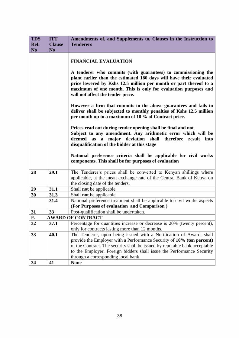
FINANCIAL EVALUATION
A tenderer who commits (with guarantees) to commissioning the
plant earlier than the estimated 180 days will have their evaluated
price lowered by Kshs 12.5 million per month or part thereof to a
maximum of one month. This is only for evaluation purposes and
will not affect the tender price.
However a firm that commits to the above guarantees and fails to
deliver shall be subjected to monthly penalties of Kshs 12.5 million
per month up to a maximum of 10 % of Contract price.
Prices read out during tender opening shall be final and not
Subject to any amendment. Any arithmetic error which will be
deemed as a major deviation shall therefore result into
disqualification of the bidder at this stage
National preference criteria shall be applicable for civil works
components. This shall be for purposes of evaluation
28 29.1 The Tenderer’s prices shall be converted to Kenyan shillings where
applicable, at the mean exchange rate of the Central Bank of Kenya on
the closing date of the tenders.
29 31.1 Shall not be applicable
30 31.3 Shall not be applicable
31.4 National preference treatment shall be applicable to civil works aspects
(For Purposes of evaluation and Comparison )
31 33 Post-qualification shall be undertaken.
F. AWARD OF CONTRACT
32 37.1 Percentage for quantities increase or decrease is 20% (twenty percent),
only for contracts lasting more than 12 months.
33 40.1 The Tenderer, upon being issued with a Notification of Award, shall
provide the Employer with a Performance Security of 10% (ten percent)
of the Contract. The security shall be issued by reputable bank acceptable
to the Employer. Foreign bidders shall issue the Performance Security
through a corresponding local bank.
34 41 None

39
SECTION IV: CONDITIONS OF CONTRACT
1. Definitions
1.1 In this Contract, except where context otherwise requires, the following terms shall
be interpreted as indicated;
a. “Bills of Quantities” means the priced and completed Bill of Quantities
forming part of the tender [where applicable].
b.
c. “General Condition of Contract (GCC)” means Condition of Contract and
Special Condition of Contract
d. “Schedule of Rates” means the priced Schedule of Rates forming part
of the tender [where applicable].
e. “Completion Date” means the date of completion of the Works as certified
by the Employer’s Representative.
f. “Contract” means the agreement entered into by the Employer and the
Contractor as recorded in the Agreement Form and signed by the parties.
g. “Contractor” refers to the person or corporate body whose tender to
carry out the Works has been accepted by the Employer.
h. “Contractor’s Tender” i s the completed tendering document submitted
by the Contractor to the Employer.
i. “Contract Price” is the price stated in the Notification of Award.
j. “Days” are calendar days; “Months” are calendar months.
k. “Defect” is any part of the Works not completed in accordance with the
Contract.
l. “Defects Liability Certificate” is the certificate issued by Employer’s
Representative upon correction of defects by the Contractor.
m. “Defects Liability Period” is the period named in the Appendix to
Conditions of Contract and calculated from the Completion Date.
n. “Project delivery period” is estimated to be 180 days from the Start Date.

40
o. “Drawings” include calculations and other information provided or
approved by the Employer’s Representative for the execution of the
Contract.
p. “Employer/ Procuring Entity” is Kenya Electricity Generating Company
Limited of Stima Plaza, Kolobot Road, Parklands, P. O. Box 47936 Nairobi
(00100). Kenya.
q. “Employer’s Representative” is the person appointed by the Employer
and notified to the Contractor for the purpose of supervision of the Works.
r. “Equipment” is the Contractor’s machinery and vehicles brought
temporarily to the Site for the execution of the Works.
s. “Services” means “Re-location of One GE Frame 6 Gas Turbine Plant
from Embakasi in Nairobi to Muhoroni near Kisumu ( approximately
310 km)’
t. “Site” means the place or places where the permanent Works are to be
carried out including workshops where the same is being prepared.
u. “Materials” are all supplies, including consumables, used by the
Contractor for incorporation in the Works.
v. “Specification” means the Specification of the Works included in the
Contract.
w. “Start Date” is the date when the Contractor shall commence execution of
the Works upon the Notice to Commence.
x. “Subcontractor” is a person or corporate body who has a Contract with the
Contractor to carry out a part of the Work in the Contract, which includes
Work on the Site.
y. “Temporary works” are works designed, constructed, installed, and
removed by the Contractor which are needed for construction or installation
of the Works.
z. “A Variation” is an instruction given by the Employer’s Representative
which varies the Works.
aa. “The Works” are what the Contract requires the Contractor to construct,
install, and turnover to the Employer.
2. Contract Documents

41
2.1 The following documents shall constitute the Contract documents and shall be
interpreted in the following order of priority;
a. Contract Agreement,
b. Notification of Award
c. Letter of Acceptance
d. Conditions of Contract
e. Technical Specifications
f. Drawings,
g. Bills of Quantities or Schedule of Rates (whichever is applicable)
h. Contractor’s Tender
i. Applicable Addenda and Clarifications
3. Employer’s Representative’s Decisions
3.1 Except where otherwise specifically stated, the Employer’s Representative will
decide contractual matters between the Employer and the Contractor in the role
representing the Employer.
4. Works, Language and Law of Contract
4.1 The Contractor shall construct and install the Works in accordance with the
Contract documents. The Works may commence on the Start Date and shall be
carried out in accordance with the Program submitted by the Contractor, as updated
with the approval of the Employer’s Representative, and complete them by the
Intended Completion Date.
4.2 The ruling language of the Contract shall be English language and the law governing
the Contract shall be the law of the Republic of Kenya.
5. Safety, Temporary works and Discoveries
5.1 The Contractor shall be responsible for design of temporary works and shall obtain
approval of third parties to the design of the temporary works where required.
5.2 The Contractor shall be responsible for the safety of all activities on the Site.
5.3 Anything of historical or other interest or significant value unexpectedly discovered
on the Site shall be the property of the Employer. The Contractor shall notify the
Employer’s Representative of such discoveries and carry out the Employer’s
Representative’s instructions for dealing with them.
6. Work Program and Sub-contracting

42
6.1 Within 7 (seven) days after Site possession date, the Contractor shall submit to the
Employer’s Representative for approval a program showing the general methods,
arrangements, order and timing for all the activities in the Works.
6.2 The Contractor may sub-contract the Works (but only to a maximum of 25%
(twenty-five percent) of the Contract Price) with the approval of the Employer’s
Representative. However, he shall not assign the Contract without the approval of
the Employer in writing. Sub-contracting shall not alter the Contractor’s
obligations.
6.3 The main contractor shall be responsible for all the activities of their Sub-
contractors.
7. The site
7.1 The Employer shall give possession of all parts of the Site to the Contractor.
7.2 The Contractor shall allow the Employer’s Representative and any other person
authorised by the Employer’s Representative, access to the Site and to any place
where work in connection with the Contract is being carried out or is intended to be
carried out.
8 Instructions
8.1 The Contractor shall carry out all instructions of the Employer’s Representative
which are in accordance with the Contract.
9 Extension of Completion Date
9.1 The Employer’s Representative shall extend the Completion Date if an occurrence
arises which makes it impossible for completion to be achieved by the Intended
Completion Date. The Employer’s Representative shall decide whether and by how
much to extend the Completion Date.
9.2 For the purposes of this clause, the following occurrences shall be valid for
consideration;
Delay by:-
(a) Force majeure; or
(b) Reason of any exceptionally adverse weather conditions; or
(c) reason of civil commotion, strike or lockout affecting any of the trades employed
upon the Works or any of the trades engaged in the preparation, manufacture or
transportation of any of the goods or materials required for the Works, or

43
(d) Reason of the Employer’s Representative’s instructions issued under these
Conditions; or
(e) reason of the contractor not having received in due time necessary instructions,
drawings, details or levels from the Employer’s Representative for which he
specifically applied in writing on a date which, having regard to the date for
Completion stated in the appendix to these Conditions or to any extension of time
then fixed under this clause, was neither unreasonably distant from nor
unreasonably close to the date on which it was necessary for him to receive the
same; or
(f) delay on the part of artists, tradesmen or others engaged by the Employer in
executing work not forming part of this Contract; or
(g) reason of delay by statutory or other services providers or similar bodies engaged
directly by the Employer; or
(h) reason of opening up for inspection of any Work covered up or of the testing or
any of the Work, materials or goods in accordance with these conditions unless the
inspection or test showed that the Work, materials or goods were not in accordance
with this Contract; or
(i) reason of delay in appointing a replacement Employer’s Representative; or
(j) reason of delay caused by the late supply of goods or materials or in executing
Work for which the Employer or his agents are contractually obliged to supply or
to execute as the case may be; or
(k) delay in receiving possession of or access to the Site.
10 Management Meetings
10.1 A Contract management meeting shall be held regularly and attended by the
Employer’s Representative and the Contractor. Its business shall be to review the
plans for the remaining Work. The Employer’s Representative shall record the
business of management meetings and provide copies of the record to those attending
the meeting and the Employer. The responsibility of the parties for actions to be
taken shall be decided by the Employer’s Representative either at the management
meeting or after the management meeting and stated in writing to all who attend the
meeting.
10.2 Communication between parties shall be effective only when in writing.
11 Defects
11.1 T h e Employer’s Representative shall inspect the Contractor’s work and notify
the Contractor of any defects that are found. Such inspection shall not affect the

44
Contractor’s responsibilities. The Employer’s Representative may instruct the
Contractor to search for a defect and to uncover and test any Work that the
Employer’s Representative considers may have a defect. Should the defect be found,
the cost of uncovering and making good shall be borne by the Contractor. However
if there is no defect found, the cost of uncovering and making good shall be treated as
a variation and added to the Contract Price.
11.2 The Employer’s Representative shall give notice to the Contractor of any defects
before the end of the Defects Liability Period, which begins at Completion. Warranty
period for new equipment and Control systems shall be minimum of twelve (12).
11.3 Every time notice of a defect is given, the Contractor shall correct the notified defect
within the length of time specified by the Employer’s Representative’s notice. If the
Contractor has not corrected a defect within the time specified in the Employer’s
Representative’s notice, the Employer’s Representative will assess the cost of having
the defect corrected by other parties and such cost shall be treated as a variation and
be deducted from the Contract Price.
12 Bills of Quantities/Schedule of Rates
12.1 T h e Bills of Quantities/Schedule of Rates shall contain items for the construction,
installation, testing and commissioning of the Work to be done by the Contractor.
The Contractor will be paid for the quantity of the Work done at the rates in the
Bills of Quantities/Schedule of Rates for each item. Items against which no rate is
entered by the Tenderer will not be paid for when executed and shall be deemed
covered by the rates for other items in the Bills of Quantities/Schedule of Rates.
12.2 Where Bills of Quantities do not form part of the Contract, the Contract Price shall
be a lump sum (which shall be deemed to have been based on the rates in the
Schedule of Rates forming part of the tender) and shall be subject to re-measurement
after each stage.
13 Variations
13.1 The Contractor shall provide the Employer’s Representative with a quotation for
carrying out the variations when requested to do so. The Employer’s
Representative shall assess the quotation and shall obtain the necessary authority
from the Employer before the variation is ordered.
13.2 If the Work in the variation corresponds with an item description in the Bill of
Quantities/Schedule of Rates, the rate in the Bill of Quantities/Schedule of Rates
shall be used to calculate the value of the variation. If the nature of the Work in the
variation does not correspond with items in the Bill of Quantities/Schedule of Rates,
the quotation by the Contractor shall be in the form of new rates for the relevant
items of Work.

45
13.3 If the Contractor’s quotation is unreasonable, the Employer’s Representative may
order the variation and make a change to the Contract Price, which shall be based on
the Employer’s Representative’s own forecast of the effects of the variation on the
Contractor’s costs.
14 Payment Certificates and Final Account
14.1 The Contractor shall be paid after each of the following stages of work listed here
below (subject to re-measurement by the Employer’s Representative of the work
done in each stage before payment is made). In case of lump-sum Contracts, the
valuation for each stage shall be based on the quantities so obtained in the re-
measurement and the rates in the Schedule of Rates.
14.2 Upon deciding that Works included in a particular stage are complete, the Contractor
shall submit To the Employer’s Representative his application for payment. The
Employer’s Representative shall check, adjust if necessary and certify the amount to
be paid to the Contractor within 21 (twenty-one) days of receipt of the
Contractor’s application .The Employer shall pay the Contractor the amounts so
certified within 30 ( t h i r t y ) days of the date of issue of each Interim
Certificate.
14.3 The Contractor shall supply the Employer’s Representative with a detailed final
account of the total amount that the Contractor considers payable under the Contract
before the end of the Defects Liability Period. The Employer’s Representative shall
issue a Defect Liability Certificate and certify any final payment that is due to the
Contractor within 30 (thirty) days of receiving the Contractor’s account if it is
correct and complete. If it is not, the Employer’s Representative shall issue within
21 (twenty-one) days a schedule that states the scope of the corrections or additions
that are necessary. If the final account is still unsatisfactory after it has been
resubmitted, the Employer’s Representative shall decide on the amount payable to
the Contractor and issue a Final Payment Certificate. The Employer shall pay the
Contractor the amount so certified within 60 (sixty) days of the issue of the Final
Payment Certificate.
14.4 If the period laid down for payment to the Contractor upon each of the Employer’s
Representative’s Certificate by the Employer has been exceeded, the Contractor
shall be entitled to claim simple interest calculated pro-rata on the basis of the
number of days delayed at the Central Bank of Kenya’s average base lending rate
prevailing on the first day the payment becomes overdue. The Contractor will be
required to notify the Employer within 15 (fifteen) days of receipt of delayed
payments of his intentions to claim interest.
14.5 Payment Terms and Documents
The payment terms will be as follows:

46
MILESTONE
PERCENTAGE
Payment
supporting
documents
1) Completion of formation and pouring
of the Gas turbine foundation.
15%
TBA
2) On dismantling, packing of the plant at
Embakasi, transportation and delivery
of the plant at Muhoroni
15%
TBA
3) Upon Installation and Commissioning. 35% TBA
4) Upon Completion of all Civil works. 20% TBA
5) On Completion of reliability run 5% TBA
6) Upon Submission of as-built drawings,
operating and maintenance manuals of
new systems and commissioning test
reports for all systems
5%
TBA
7) Expiry of twelve (12) months of
Turbine control equipment, Generator
excitation system, automatic voltage
regulator
5%
TBA
a) The payments shall be made thirty (30) days after receipt of certified invoice,
payment certificates, Engineers completion certificate where applicable, Service Entry
sheet and authorization letters confirming that the invoice material, engineering works
has been delivered and/or service has been rendered in accordance with the contract.
b) The payments shall be made through telegraphic transfers (TT’s) to the bank accounts
indicated on the certified invoices forwarded for payment.
c) The currency of the invoice shall be a currency easily convertible.
d) Upon request from the supplier the payment can be made through a letter of credit.
15. Insurance
15.1 The Contractor shall provide, in the joint names of the Employer and the Contractor,
insurance cover from the Commencement Date to the end of the Defects Liability
Period. The minimum insurance covers shall be Contractor’s All Risks and the
minimum amount of third party insurance shall be Kenya Shillings Ten Million
(KShs.10,000,000/-) per occurrence with the number of occurrence unlimited.
The cover shall include the following events which are due to the Contractor’s risks:
(a) Loss of or damage to the Works, Plant, and Materials;

47
(b) Loss of or damage to Equipment;
(c) Loss of or damage to property (except the Works, Plant, Materials, and Equipment)
in connection with the Contract; and
(d) Personal injury or death.
15.3 Policies and certificates for insurance shall be delivered by the Contractor to the
Employer’s Representative for the Employer’s Representative approval before the
Commencement Date. All such insurance shall provide for compensation to be
payable in the types and proportions of currencies required to rectify the loss or
damage incurred.
15.4 If the Contractor does not provide any of the policies and certificates required, the
Employer may effect the insurance which the Contractor should have provided and
recover the premiums the Employer has paid from payments otherwise due to the
Contractor or, if no payment is due, the payment of the premiums shall be a debt due.
15.5 Alterations to the terms of insurance shall not be made without the approval of the
Project Manager.
15.6 The Contractor shall ensure that they are at all times in compliance with statutory
requirements and provisions pertaining to the requisite applicable insurance policies.
16. Liquidated Damages
If the Contractor fails to deliver the goods and/or services within the period(s)
specified in the Contract, the Employer shall, without prejudice to its other remedies,
deduct from the Contract Price liquidated damages sum equivalent to 1% of the price
of the undelivered part of the contract per day up to a maximum deduction of 10%.
After this, the parties may consider termination of the Contract. In addition any delay
in commencement of reliability run will attract a penalty of 1% of the contract price
per day.
17. Completion and Taking Over
17.1 Upon deciding that the Work is complete the Contractor shall request the
Employer’s Representative to issue a Certificate of Completion of the Works.
The Employer shall take over the Site and the Works within seven (7) days of
the Employer’s Representative issuing a Certificate of Completion.
18. Termination

48
18.1 T h e Employer or the Contractor may terminate the Contract if the other party
causes a fundamental breach of the Contract. These fundamental breaches of
Contract shall include, but shall not be limited to, the following;
(a) the Contractor stops Work for 30 (thirty) days continuously without reasonable
cause or authority from the Employer’s Representative;
(b) the Contractor is declared bankrupt or goes into liquidation other than for a
reconstruction or amalgamation;
(c) a payment certified by the Employer’s Representative is not paid by the Employer to
the Contractor within 30 (thirty) days after the expiry of the payment periods
stated in sub clauses 14.2 and 14.3 herein above.
(c) the Employer’s Representative gives notice that failure to correct a particular defect is
a fundamental breach of Contract and the Contractor fails to correct it within a
reasonable period of time.
18.2 If the Contract is terminated, the Contractor shall stop Work immediately, and leave
the Site as soon as reasonably possible. The Employer’s Representative shall
immediately thereafter arrange for a meeting for the purpose of taking record of the
Works executed and materials, goods, equipment and temporary buildings on Site.
19. Payment upon Termination
19.1 T h e Employer may employ and pay other persons to carry out and complete the
Works and to rectify any defects and may enter upon the Works and use all materials
on Site, plant, equipment and temporary works.
19.2 The Contractor shall, during the execution or after the completion of the Works
under this clause, remove from the Site as and when required within such
reasonable time as the Employer’s Representative may in writing specify any
temporary buildings, plant, machinery, appliances, goods or materials belonging to
him, and in default thereof , the Employer may (without being responsible for any
loss or damage) remove and sell any such property of the Contractor, holding the
proceeds less all costs incurred to the credit of the Contractor.
19.3 Until after completion of the Works under this clause, the Employer shall not be
bound by any other provision of this Contract to make any payment to the
Contractor, but upon such completion as aforesaid and the verification within a
reasonable time of the accounts therefore the Employer’s Representative shall certify
the amount of expenses properly incurred by the Employer and, if such amount added
to the money paid to the Contractor before such determination exceeds the total
amount which would have been payable on due completion in accordance with this
Contract, the difference shall be a debt payable to the Employer by the Contractor;
and if the said amount added to the said money be less than the said total amount,
the difference shall be a debt payable by the Employer to the Contractor.

49
20. Corrupt Gifts and Payments of Commission
20.1 T h e Contractor shall not;
(a) Offer or give or agree to give to any person in the service of the Employer any gifts
or consideration of any kind as an inducement or reward for doing or forbearing to
do or for having done or forborne to do any act in relation to the obtaining or
execution of this or any other contract with the Employer or for showing or
forbearing to show favour or disfavour to any person in relation to this or any other
contract with the Employer.
(b) Any breach of this Condition by the Contractor or by anyone employed by him or
acting on his behalf (whether with or without the knowledge of the Contractor) shall
be an offence under the Laws of Kenya.
21. Settlement of Disputes
21.1 The Employer and the Contractor shall make every effort to resolve amicably by
direct informal negotiation any disagreement or dispute arising between them under
or in connection with the Contract.
21.2 Any dispute between the Parties as to matters arising pursuant to this Contract or its
interpretation that cannot be settled amicably within thirty (30) days after receipt by
one Party of the other Party’s request for such amicable settlement shall be referred
for settlement by a single arbitrator. The Arbitrator shall be agreed upon by the
Parties within thirty days (30) days of the notification of a dispute by either party to the
other and in default of agreement as to the single arbitrator the same shall be
appointed by the Chairman for the time being of the Chartered Institute of the
Arbitrators of Kenya (Kenya Chapter). Every award made under this Clause shall be
expressed to be made under the Arbitration Act 1995 or other Act or Acts for the time
being in force in Kenya in relation to arbitration.
21.3 The seat of the arbitration shall be in Nairobi and language thereof English
22 Taxes
22.1.1 “Taxes” means all present and future taxes, levies, duties, charges, assessments,
deductions or withholdings whatsoever, including any interest thereon, and any
penalties and fines with respect thereto, wherever imposed, levied, collected, or
withheld pursuant to any regulation having the force of law and "Taxation" shall be
construed accordingly.
Local Taxation
22.1.2 Nothing in the Contract shall relieve the Contractor and/or his Sub-Contractors from
their responsibility to pay any taxes, statutory contributions and levies that may be
levied on them in Kenya in respect of the Contract. The Contract Price shall include
all applicable taxes and shall not be adjusted for any of these taxes.

50
22.1.3 The Contractor shall be deemed to be familiar with the tax laws in the Employer's
Country and satisfied themselves with the requirements for all taxes, statutory
contributions and duties to which they may be subjected during the term of the
Contract.
22.1.4 In instances where discussions are held between the Employer and the Contractor
regarding tax matters, this shall not be deemed to constitute competent advice and
hence does not absolve the Contractor of their responsibility in relation to due
diligence on the tax issue as per 22 .1 .3 above.
Tax Deduction
22.1.5 If the Employer is required to make a tax deduction by Law, then the deduction
shall be made from payments due to the Contractor and paid directly to the Kenya
Revenue Authority. The Employer shall upon remitting the tax to Kenya Revenue
Authority furnish the Contractor with the relevant tax deduction certificates.
22.1.6 Where the Contractor is paid directly by the Financiers and the Employer is not
able to deduct tax, then the Contractor will be required to pay the tax deduction to
Kenya Revenue Authority in the name of the Employer and furnish the Employer
with an original receipt thereof as evidence of such payment. In absence of the said
evidence, the Employer will not process any subsequent payments to the Contractor.
Tax Indemnity
22.1.7 The Contractor shall indemnify and hold the Employer harmless from and against
any and all liabilities, which the Employer may incur for any reason of failure by
the Contractor to comply with any tax laws arising from the execution of the
Contract whether during the term of the Contract or after its expiry.
22.1.8 The Contractor warrants to pay the Employer (within 14 (fourteen) days of demand
by the Employer), an amount equal to the loss, liability or cost which the Employer
determines has been (directly or indirectly) suffered by the Employer for or on
account of the Contractor’s Tax liability arising from the Contract.
22.1.9 Where the amount in 22.1.8 above remains unpaid after the end of the 14 (fourteen)
days moratorium, the Employer shall be entitled to compensation for financing
charges.
Change in the Applicable Law
If, after the date of this Contract, there is any change in the Applicable Law
with respect to taxes, statutory deductions or minimum labour conditions which
increase the cost incurred by the Consultant in performing the Services, then the

51
Service fee payable to the Consultant under this Contract shall be adjusted
accordingly.
23. Governing Law
The contract shall be governed by Laws of Kenya.
24. Force Majeure
24.1 Neither party shall be held liable for failing to perform its obligations under the
contract if the failure has been caused exclusively by a force majeure. For the
purposes of this Contract “Force Majeure” means an unforeseeable event beyond the
control of either party and not involving either party’s fault or negligence.
24.2 If a Force Majeure situation arises, the affected party shall promptly notify the other
party in writing of such condition and the cause thereof. The affected party shall
continue to perform its obligations under the Contract as far as is reasonably
practical.
24.3 An occurrence of a Force Majeure shall not relieve a party of liability arising out of a
breach or non-performance of an obligation which occurred prior to the Force
Majeure.
25 Miscellaneous Provisions
25.1 The rights and remedies provided hereunder are not exclusive of any other remedy
which is otherwise available at law.
25.2 Nothing in this agreement shall be construed to imply a partnership, agency or any
other relationship between the parties save to the extent provided herein.
25.3 Termination of this Agreement for any cause shall not release either party from any
liability which at the time of termination has already accrued to the other Party or
which thereafter may accrue in respect of any act or omission prior to such
termination.
25.4 Each party acknowledges that in agreeing to enter into this agreement it has not
relied on any express or implied representation, warranty, collateral contract or other
assurance (except those set out in this agreement and the documents referred to in it)
made by or on behalf of any other party before the signature of this Agreement.
25.5 Where the approval, agreement or consent of any Party is required under any
provision of this Agreement to any particular matter, such approval, Agreement or
consent may be given subject to such terms and conditions as that Party may require
and any breach of such terms and conditions shall ipso facto be deemed to be a
breach of this Agreement.
25.6 Notwithstanding anything to the contrary contained herein, this Agreement shall
endure for the benefit of and be binding on the successors-in-title and permitted

52
assigns of the parties. Accordingly, the rights and obligations of each Party arising
out of or pursuant to this Agreement or its termination or cancellation shall devolve
upon and bind its legal representatives, successors-in-title and permitted assigns.
25.7 To the extent that any court of competent jurisdiction should determine that any
term or provision of this Agreement is void, the said term or provision is to be
interpreted and amended so as to be valid and the parties undertake to negotiate
in good faith to cure any such void. The remainder of the agreement shall
remain valid notwithstanding
25.8 No waiver of any right under this agreement shall be effective unless contained in
writing signed by the waiving Party. No waiver of any right arising from any breach
or non-performance shall be deemed to waive any future such right or any other right
arising under this agreement. The failure of either Party at any time or for any period
of time to enforce any term of this agreement shall not be construed to waive such
term or the right of either Party to enforce each and every such term.
26 Authorized Representatives
26.1 Any action required or permitted to be taken, and any document required or
permitted to be executed, under this Contract by the Employer or the Contractor
shall be taken or executed by the officials specified below unless otherwise agreed
between the Parties in writing;
Employer ’s Authorized representative is:
The Managing Director & Chief Executive Officer or his designated representative as
may be communicated from time to time.
Contractor ’s Authorized representative is:
…………………………………………………..
26.2 In case the Contractor consists of a joint venture of more than one entity, the
Members shall specify in writing and before execution of this Agreement, the entity
authorized to act on their behalf in exercising the entire Contractor’s rights and
obligations towards the Employer under this Contract, including without limitation
the receiving of instructions and payments from the Employer.
27 Notices
27.1 Any notice required to be given by a party under this agreement shall be
considered effectively made when delivered to a party’s address stated herein or
by way of registered mail or through the party’s email address of
correspondence ordinarily used to exchange information by the Parties. The
parties’ addresses for purposes of this agreement are:
For the Employer:

53
The Company Secretary & Legal Affairs Director
Company Secretary &Legal Affairs Director
Kenya Electricity Generating Company Limited
10th Floor, KenGen Pension Plaza 2,
P O Box 47936-00100 NAIROBI, KENYA TEL: (254) (020) 3666706
For the Contractor:
……………………….
27.2 This agreement, the schedule and the documents referred to in it contain the entire
agreement of the parties relating to the transactions contemplated herein and
supersede any previous agreement between the parties, oral or otherwise. No
addition to, variation, modification or amendment to this Agreement shall be
effective unless in writing and duly signed by or on behalf of the parties.
28 Warranties and Covenants
The Contractor warrants and covenants with the Employer that:
28.1 The Contractor has all necessary power and authority to carry on its business as
presently conducted and to enter into and perform its obligations under this Agreement.
28.2 The execution, delivery and performance of this Agreement by Contractor has been
duly authorized by all requisite company action and the performance of its obligation
hereunder will not offend or conflict with any law or contractual commitments
28.3 There is no action, suit or proceeding, at law or in equity, or official investigation by
or before any governmental authority, arbitral tribunal or any other body pending or, to
the knowledge of Contractor threatened, against or affecting Contractor or any of its
properties, rights or assets, which could reasonably be expected to result in a material
adverse effect on Contractor’s ability to perform its obligations under this Agreement
or on the validity or enforceability of this Agreement.
28.4 The Contractor and the Contractor’s agents and representatives have visited,
inspected and are familiar with the Site, its physical condition, roads, access rights,
utilities, topographical conditions and air quality conditions, and have performed all
reasonable investigations necessary to determine that the Site is suitable for the
construction and installation of the plant, and are familiar with the local and other
conditions which may be material to the Contractor’s performance of its obligations
under this Agreement (including, but not limited to transportation, seasons and
climates, access, the handling and storage of materials and availability and quality of
labor and materials).
28.5 The Contractor owns or will obtain the legal right to use all patents, rights to patents,
trademarks, copyrights and licenses necessary for the performance by the Contractor of

54
this Agreement and the transactions contemplated hereby, without any material conflict
with the rights of others.
28.6 Contractor has obtained or will procure statutory and other governmental permits and
licenses necessary for the successful performance of its obligations hereunder, and will
abide by the conditions of such licenses or permits.
28.7 The Contractor (including where applicable, through its relationships with
Subcontractors and its Affiliates) possesses the know-how and wherewithal to perform
its obligations under the Contract.

55
SECTION V- DRAWINGS
SEE DRAWINGS AS ATTACHMENT AS MARKED:-
MUHORONI GAS TURBINE NO. 2 FINAL DRAWINGS

56
SECTION VI: SCHEDULE OF REQUIREMENTS AND TECHNICAL
SPECIFICATIONS
TECHNICAL SPECIFICATIONS
1. SCOPE
This specification is for the Dismantling, Transportation, Supply of Goods, Civil
Works, Assembly and Commissioning from Embakasi in Nairobi to Muhoroni near
Kisumu.
Embakasi Gas Turbine Power Plant is located near Kenya Power Embakasi Sub-station,
Industrial area in Nairobi. Muhoroni Site is located in Kericho county about 310 KM from
Nairobi along Nairobi – Kisumu highway. The road is tarmacked all through. To access
Embakasi Site, one has to branch off at Libra House on Momabasa-Nairobi highway,
opposite Sameer (formerly Firestone) and drive past KPA Inland Container Depot up to
Kenya Power Embakasi Substation.
KenGen will hand over the Gas turbine at Embakasi in a working condition. The turbine shall
be tested in the presence of the contractor to confirm the running parameters and conditions
of the machine before handover to the Contractor.
Due care is expected when transporting the Gas Turbine Plants to ensure that no damage to
the equipment is experienced. It is expected that the all civil works at Muhoroni site where
the Gas Turbine Plants will be relocated will have been completed by the time of relocation.
The Contractor Shall provide all the necessary equipment and lifting gear required for
dismantling, transportation and assembly of the Gas turbine, generator and all associated
auxiliary plant.
Details of the works/tasks, dimensions and weights of the various plant components will be
confirmed during the mandatory site visit on the date and time indicated in the tender.
Critical Activities
a. Mobilization time upon award of contract
b. Dismantling time of Gas Turbine plant and auxiliary equipment at Embakasi

57
c. Transportation time of Gas Turbines Plant and auxiliary equipment from
Embakasi to Muhoroni.
d. Assembling time of the Gas turbine plant and auxiliary equipment at
Muhoroni
e. Commissioning of the plant
(The period of executing each of the above tasks, in days, shall be stated and
shall be used as an evaluating criteria.)
COMPONENTS OF THE GAS TURBINE PLANT
ITEM DESCRIPTION APPROXIMATE WEIGHT
1 Generator and load gear 80 tonnes
2 Turbine, exhaust plenum,
Accessory gear box
92 tonnes
3 Chimney and Exhaust transition
duct
11.31 tonnes
4 Air intake filter house 10 tonnes
5 Inlet transition duct 4.6 tonnes
6 Inlet duct 3 tonnes
7 Inlet elbow 4 .1 tonnes
8 Cooling Water module and
associated pipe work
Site visit
9 Fuel forwarding skid & associated
pipework
Site visit
10 Cooling water pump (Synchronous
condenser mode) and associated
pipework
Site visit
11 Main Compressor water washing
system and associated pipework
Site Visit
12 Auxilliary transformer & 11KV
Line Side Cubicle
Site visit
The Contractor shall undertake the following works under their responsibility:-
a) Civil Works
Survey and soil testing, earth works, drainage system, construction of all Gas Turbine,
Generator and auxilliary equipment foundations including Air Inlet Filter Housing (AIFH),
auxiliary transformer, Main Compressor water washing system, Construction of Draw pits,
construction of station earth mat, cable trenches and provision of trench covers, Construction
of foundation for fuel day-service tank and other items as detailed in the bills of quantity.
Where quantities are provided in the bills, these are provisional and will be re-measured.
b) Packing for Transport

58
Special attention must be given especially to sensitive equipment e.g. control panels and
generator to ensure protection against weather and dust during storage, transport and even
when awaiting installation.
c) Transportation
The contractor will organize transport of all components to Muhoroni and pay all statutory
charges especially permit by Kenya National Highways Authority (KeNHA). KenGen will
facilitate by providing letters introducing the Contractor to the relevant authorities. Any
breakages while under handling of the contractor will be to the contractors risk and the
contractor will be required to provide proof of insurance of about Kshs. 100 Million.
The transporter shall adhere to axle load limits as specified by KeNHA throughout the route
from Embakasi, Nairobi to Muhoroni. The Modular Low Loader will be preferred for the
heavy equipment (Generator and Turbine).
d) Dismantling
Dismantling – Disconnection and removal of Piping systems, Off-base cable disconnection,
HV disconnection up to Unit Step-up Transformer, Circuit Breaker disconnection,
Disconnection of Gearbox from turbine, Support of the gearbox and turbine high speed shafts
shaft, removal and disassembly of Exhaust System, Transition duct and Silencers, Removal
of Inlet Ducting, transition duct, Filters and Disassembly of Air Inlet Filter House,
Disconnection and Removal of Control System, Unbolting of units from base, Dismantling of
Cooling modules and Fuel Forwarding Skids, Cooling water pump for synchronous
condenser mode, control panel, Generator protection Panel, and AC & DC motor Control
Centre. 110V standby batteries and charging system.
Embakasi site to be left in a safe and environmentally acceptable condition.
e) Installation and Erection
Installation and Erection – Mounting of Gas turbine Generator to base, Coupling of Turbine
to Load Package, re-assembly of Air inlet Filter House, Erection, Installation of Air inlet
Ducting System, Re-assembly and Installation of Exhaust System, Transition duct, Silencers
and Stack, Lagging and cladding of the exhaust, Installation of off-base equipment (cooling
modules, Compressor waterwashing system, synchronous mode cooling water pump, fuel
forwarding skid), Control Room, Installation of Generator Circuit Breaker/11 kV switchgear,
installation of instruments for energy billing, metering and 11 kV system protection,
Installation of LV and Control interconnection off-base cables, Fuel and Drains Tie-ins. 110V
standby batteries and charging system.
f) Pre-Commissioning, Commissioning and Reliability Testing
Pre-commissioning and Commissioning – Mechanical Alignment checks, Integrity checks of
Mechanical Tie-ins and off-base connections, Dry loop checks, Instrumentation and
Electrical checks, Power up checks, Control system checks, Hot loop checks, Control
Systems Site Acceptance Tests, ratchet checks, running checks, Full Speed No Load (FSNL)
checks, Synchronization checks and load test.
Reliability tests shall be carried out for a period of 30 days.

59
g) Supply of Goods
1. Supply of Foundation Hardware for the turbine, generator, gearbox and all auxiliary
equipment. Contractor to provide quantities and specifications for the Gas turbine
gearbox and Generator foundation hardware.
2. Supply Two (2) Containers: 20 feett for 11kV switchgear, and 40 feet for control
room. Kengen will provide an additional One (1) 40 feet Container for the Control
room . The Containers should be adequately air conditioned, windows and doors to
be provided as per the general arrangement drawing provided. The containers shall
be complete with 1.5m high steel support structures to be mounted on concrete
plinths.
3. Supply and construction of a functioning station earth mat and its interconnection
cable to KPLC Muhoroni switchyard.
4. All Packing, Loading, Transport and Offloading Materials, Consumables, LV
Cables, Control cables and HV interconnection cables .
5. New Electrical Control Systems
(New Control Systems to be Supplied, Installed and Commissioned)
a) Turbine Control System
Supply, Installation and Commissioning of the new Turbine Control System to
replace the existing old Mark V Turbine Control System – to fully interface to
existing controls and field devices and commission the Turbine Control System at
Muhoroni site. This system shall include a minimum of all control and monitoring
functionalities within the existing Mark V system. Apart from Load Control, the
Turbine Control Governor shall be capable of operation in both Speed Droop and
Speed Isochronous Control with the synchronizing circuit breaker closed. All Turbine
Governor Modes including Isochronous Control shall be tested and commissioned.
Testing of the droop mode shall include confirmation of the droop setting through
testing. The Isochronous Mode shall facilitate operation of the Unit in isolation from
the grid. Isolated mode shall be possible with the 33/132kV power transformer off the
grid. Necessary logic shall be interfaced to the turbine control system to communicate
loss of grid and enable isolated operation. Parameters for this mode shall be duly
tuned to allow stable isolated operation. A dead band of approximately +-0.2Hz shall
be set around the load control mode to allow automatic changeover to droop mode
whenever these limits are violated to enable Unit participation in system frequency
stabilization. All the modes shall track the prevailing actual values to allow bump-less
transfers. The desired Governor Speed Droop setting of 5% shall be tested and
confirmed during commissioning. The actual parameters for the various control

60
modes such as dead-band and droop suitable for both the Unit and grid stability will
be discussed and agreed during site commission.
b) Generator Excitation System
Supply, Installation and Commissioning of the new Generator Excitation Control
System to replace the existing old Excitation System – to interface to existing controls
and field devices and fully commission the Generator Excitation System at Muhoroni
site. The excitation system shall be equipped with a minimum of Automatic Voltage
Regulator (AVR), Field Current Regulator (FCR), Reactive Power Control Regulator
(RPCR) and Power factor Control Regulator (PFCR). Each mode shall be able to
track the actual prevailing controlled parameter to facilitate bump-less transfer. It
shall be possible for the excitation system to changeover automatically to AVR with
desired droop upon reception of the isolated grid signal. The suitable droop setting
when on isolated mode shall be agreed and tested during commissioning. However,
the recommended droop setting of 5% under normal operating conditions shall be
tested and confirmed during the commissioning of the Unit. The actual parameters for
the various control modes such as dead-band and droop suitable for both the Unit and
grid stability will be discussed and agreed during site commission.
c) Generator/Turbine Fire Protection System
Supply, Installation and Commissioning of the new Generator/Turbine Fire Protection
System to replace the existing old Unit Fire System – to interface to existing controls
and field devices and to fully commission the Generator/Turbine Fire Protection
System at Muhoroni site.
All new control systems and the associated designs shall be subject to review and
approval by the employer prior to implementation
d) New Electrical Systems and Equipment
(Electrical Systems and Equipment to be Supplied, Installed and Commissioned)
1) Remote Control Capability
Remote control capability of the plant shall be provided. The remote control
room/office is located approximately 300metres away from the plant and, as such, this
shall necessitate provision of a link fiber optic cable of adequate length. The local
control terminal shall be fully duplicated at the remote office/room so as to avail both
remote control and monitoring capability. The system shall be such that all local
control, supervisory and monitory functions are fully realizable and duplicated
remotely at the designated remote control room/office. A soft or hardware selector
switch shall be provided at the local control room to facilitate choice of control from
either the local control terminal or remote control terminal.
2) Remote Emergency Protection & Alarm Facilities

61
Remote emergency protection facilities shall be provided to enable manual tripping of
the plant in the event of emergencies. These facilities, provided in the form of
normally-closed emergency push-button and hooter, shall be distinct from the remote
control terminal and be hard-wired to the turbine control system. These facilities shall
be installed at the remote control room/office. These signals shall not be routed
through the fiber optic cable but rather channeled through a control cable of
200metres with a minimum of eight cores. Four cores shall be used with the
remaining cores being treated as spares.
3) Security Lighting System
Security lighting system shall be provided along the perimeter of the GT2 Plant site in
particular and also along the entire perimeter of the site comprising GT2, GT1 and the
fuel storage area including the administrative block for the fuel contractor. Security
lights shall equally be installed within the site to ensure all strategic installations are
amply lit at night. The security lights along the fence shall be installed at intervals of
approximately 30meters. A minimum of ten security lighting points shall be provided.
The security lights along the perimeter fence shall be controlled by two independent
MCBs with a third MCB controlling the security lights strategically installed within
site and close to the strategic installations. The security lighting points along the
perimeter fence shall be installed as to alternate between the independent circuits
along the fence. The design and the wattage of the security lighting system shall be
subject to review and approval by the employer prior to installation.
4) Interconnecting 415V Power Supply Cables
Interconnecting 1000V power cables shall be supplied and installed to provide the
link between the motor control center 415V auxiliary boards of the two GT Units. The
cables shall be supplied complete with the necessary termination lugs and terminated
to the standby 415V Circuit Breakers of the two GT Plants. A total of seven single-
core aluminium conductors complete with mechanical protection with a cross-section
of 120mm2 shall be provided. Two conductors per phase and one neutral conductor
shall be installed to enable auxiliary GT1 supply to act as standby for GT2 and vice
versa. The automatic and manual control modes to facilitate choice between the main
incomer supply drawn from the Unit’s auxiliary power transformer and standby
auxiliary supply from the other Unit shall be commissioned as part of the
commissioning of the auxiliary supply system for the Unit (MCC commissioning).
All the new Electrical systems and the associated designs shall be subject to review
and approval by the employer prior to implementation
e) 11kV Instrument Transformers and Control Cabling
One set (3NO.) of 11kV, 2500/1A, 2-core current transformer of the following classes
shall be installed on the system-side or line-side of the 2500A synchronizing circuit
breaker):
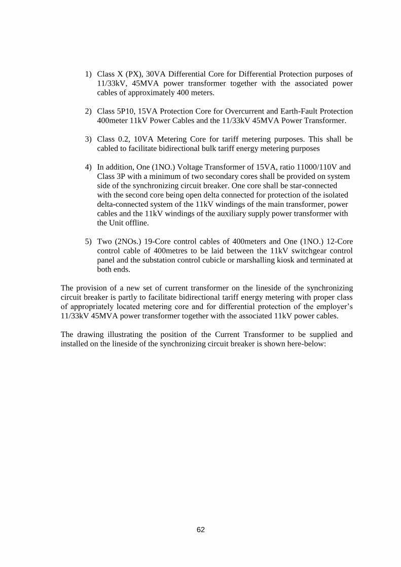
62
1) Class X (PX), 30VA Differential Core for Differential Protection purposes of
11/33kV, 45MVA power transformer together with the associated power
cables of approximately 400 meters.
2) Class 5P10, 15VA Protection Core for Overcurrent and Earth-Fault Protection
400meter 11kV Power Cables and the 11/33kV 45MVA Power Transformer.
3) Class 0.2, 10VA Metering Core for tariff metering purposes. This shall be
cabled to facilitate bidirectional bulk tariff energy metering purposes
4) In addition, One (1NO.) Voltage Transformer of 15VA, ratio 11000/110V and
Class 3P with a minimum of two secondary cores shall be provided on system
side of the synchronizing circuit breaker. One core shall be star-connected
with the second core being open delta connected for protection of the isolated
delta-connected system of the 11kV windings of the main transformer, power
cables and the 11kV windings of the auxiliary supply power transformer with
the Unit offline.
5) Two (2NOs.) 19-Core control cables of 400meters and One (1NO.) 12-Core
control cable of 400metres to be laid between the 11kV switchgear control
panel and the substation control cubicle or marshalling kiosk and terminated at
both ends.
The provision of a new set of current transformer on the lineside of the synchronizing
circuit breaker is partly to facilitate bidirectional tariff energy metering with proper class
of appropriately located metering core and for differential protection of the employer’s
11/33kV 45MVA power transformer together with the associated 11kV power cables.
The drawing illustrating the position of the Current Transformer to be supplied and
installed on the lineside of the synchronizing circuit breaker is shown here-below:

63
Fig 1: Single Line Drawing Illustrating Position of New Tariff Metering and
Protection Current Transformer
All the current signals from the Current Transformers shall be wired and cabled using
a minimum of 2.5mm2 wiring to the terminal blocks with integral CT isolation links
within the 11kV control panel. All the wiring shall be individually labeled and
ferruled and the terminal blocks equally labeled for ease of identification. The
terminal blocks shall be adequately sized as to be able to accommodate 2.5mm2
copper wiring.
f) Terminal Blocks, Internal Panel Wiring, Labelling & Ferruling
All power and control cables shall be properly lugged/terminated, marked and
labelled at both ends for ease of identification. The control cores shall be individually
ferruled at both ends, lugged prior to termination. All internal panel control wiring for
shall be carried out using a minimum of 2.5mm2 copper wiring. All terminal blocks
for control wiring shall be so sized as to accommodate 2.5mm2 copper wiring
adequately and firmly. Terminal blocks for CT signals shall be equipped with
isolation links for maintenance and testing purposes. All terminal blocks shall be
appropriately numbered and labelled for ease of reference and to aid documentation.
All devices, both old and new, shall be properly labelled and referenced in drawings.
Device list capturing device name and the relevant page of usage within the drawings
shall be prepared and included in the working and final as-built drawings
g) Shorting-Out and Bypassing of the 11kV, 1250A Circuit Breaker

64
The power evacuation arrangement in Embakasi Station is such that the Unit is
connected to two 11/66kV power transformers with each transformer rated at
23MVA. This arrangement necessitated two feeder 11kV, 1250A circuit breakers in
addition to the main 11kV, 2500A synchronizing circuit breaker. Two breakers were
necessary for protection purposes and for both operational convenience and
reliability. Tripping or maintenance of one power transformer would necessitate
operation of the Unit at half load.
However, in Muhoroni, the two circuit breakers will not be required since the Unit
will be connected to one dedicated 11/33kV, 45MVA power transformer. One of the
1250A circuit breakers has already been shorted. The shorting and bypassing of the
second 1250A circuit breaker will be carried out under this tender/contract. Currently,
the 1250A circuit breaker is connected to the 11kV bus-bars using two coppers with
cross-section area of 12mm by 100mm per copper bar. The shorting coppers bars shall
be sized as to be able to support and carry 2500A continuously without overheating.
The contractor will be required to demonstrate through calculation or acceptable
alternative means, the adequacy of the current rating (2500A) of the copper bars to be
used to bypass the circuit breaker
h) Inter-trip of the 11kV Synchronizing Circuit Breaker In Response to 33kV
Breaker Tripping/Opening
A normally-open auxiliary contact providing the status signal of the dedicated 33kV
circuit breaker shall be wired and cabled from the substation control cubicle to the
11kV circuit breaker controls and turbine controls so that the tripping or opening of
the this breaker shall automatically initiate the tripping of the 11kV synchronizing
circuit breaker and emergency shutdown of the Unit. This signal shall replace the
existing 66kV inter-trip signal
i) Pre-Commissioning & Commissioning Test Templates, Protocols/Procedures
and Installation/Commissioning Team
Commissioning protocol together with the procedures for pre-commissioning and
commissioning of all systems shall be provided one month prior to commencement of
pre-commissioning of the Unit. The protocols and procedures shall be subject to
review and approval by the employer prior to usage. The commissioning procedures
shall be expanded to include the mandatory tests required by the off-taker, KPLC.
During the review, the employer shall discuss with the contractor and make necessary
changes prior to adoption of the final pre-commissioning and commissioning
Protocols, Procedures and Test Templates.
No pre-commissioning and commissioning works shall proceed prior to provision and
discussion of these protocols and procedures. This requirement shall be applicable to
both the existing systems and new systems being provided under this tender/contract.

65
All the new systems and equipment comprising the turbine control system, excitation
control system, fire control system, remote control capability system, remote
emergency protection facilities, and security lighting system among others shall be
fully interfaced to existing systems and commissioned using the agreed procedures.
The old systems comprising generator protection systems, generator circuit breakers,
energy tariff metering systems, MCC auxiliary supply system and the associated
auxiliaries, DC supply systems, synchronizing and synchro-check systems, electrical
control panel system, Panel and local remote HMI system, mechanical plant systems
and all other pertinent plant systems integral to its operation shall be equally
interfaced and commissioned following the prior agreed procedures
All major control and protection systems comprising Turbine Control System,
Excitation System, Generator Protection System and other new control, monitoring
and protection shall be installed by experienced technicians and foremen with proven
competence. Curriculum Vitae of key installation and commissioning technicians and
engineers respectively shall be captured in the tender for review and approval by the
employer and their rates duly provided. The competence of the installation and
commissioning team shall form part of the evaluation criteria. Each key systems
including the switchgear shall be subjected to normal routine tests and other necessary
tests to be agreed with the employer prior to commencement of commissioning.
j) Documentation (Draft &Final As-built Drawings, Test Reports, Maintenance &
Operating Manuals)
All designs shall be subject to review and approval prior to adoption. Draft drawings
shall be provided for pre-commissioning and commissioning purposes. All the
changes and modifications captured during commissioning shall be marked and
reflected in the draft drawings which shall be used for running the plant prior to
submission of the as-built drawings in a period of two months after completion of
commissioning. The changes and modifications shall be captured in the drawings and
submitted for review and approval by the employer prior to submission of the final as-
built drawings.
Pre-commissioning and Commissioning Test Templates shall also be provided one
month prior to kick-off of the pre-commissioning tests. Commissioning Test Reports
and Results shall be provided two months after completion of the testing including the
reliability testing of the plant. Final payment shall be subject to submission of all
documentation including final commissioning test reports.
Four hardcopies and two soft copies of the operating and maintenance manuals for
each of the new control systems and equipment shall be provided. These copies shall
be provided in a period of two months after commissioning
k) Services
1. Engineering consisting of the following:-

66
a. Preparation and issue of all drawings (except for the ones supplied by the
client) and documentation associated for the entire scope of supply.
b. Implementation of all modifications,
c. Project logistics during the entire project.
2. Coordination of all the activities ensuring timely and safe execution of the relocation
project.
3. Commissioning each part of the installed generation system
4. Preparation and issue of “as-built” drawing of the commissioned plant.
5. All that is required to successfully relocate and commission the plant.
6. Integration to existing systems and Commissioning of all the new systems comprising
the new Turbine Control and Excitation Control Systems, Fire Protection System,
Remote Control System, CCTV System, Remote Emergency Protection System,
415V Automatic and manuals controls between the main and standby supplies and
Security Lighting System among others.
l) Exclusions (Employers Responsibility)
1. KenGen to provide site space for the Gas Turbine at Muhoroni.
2. Skilled Labour to assist in all Electrical/Mechanical Works
3. Access to plant and equipment.
m) Project Requirements (Contractor’s Responsibility)
1. Contractor to provide 415V supply board to be used for connecting to Kenya Power
supply point at Muhoroni site. Contractor to pay for the electricity connection.
2. Water and electricity for use in the works to be supplied by the Contractor.

67
Civil Works Specifications
1 Concrete Works
1.1 General
Concrete shall be a homogeneous mixture of course aggregate, water and ordinary
Portland cement. All concrete included in the works shall comply with the
requirements of BS 8110 or BSEN 206 except where modified by this specification.
All materials storage, equipment and workmanship for concrete shall be in accordance
with good engineering practice and shall be subject to the approval of the Engineer.
In respect to the aggregates cement and mix design concrete mix designs shall be in
accordance with the Concrete Society Technical Report TR 30 ‘Alkali Silica Reaction
- Minimizing the risk to concrete’ published by the Concrete Society, Riverside
House, 4 Meadows Business Park, Station Approach, Blackwater, Camberley, Surrey,
GU17 9AB, UK.
1.2 Materials for Concrete
1.2.1 Cement
Unless otherwise directed by the Engineer, cement used in the works shall be Portland
Cement complying with the requirements of BS 12 Portland Cement (Ordinary and
Rapid Hardening or BS 1370 (Low Heat Portland Cement) and shall be manufactured
by an approved process. In the event of written authority being issued by the
Engineer to use any other type of cement it shall comply with the relevant British
Standard. No blending or mixing of cements will be allowed.
In addition the cement shall have an alkali content expressed as Na2O equivalent of
not more than 0.6% by weight.
1.2.2 Aggregates
Aggregates used for mixing concrete shall comply with requirements of BS 882 and
each size of aggregate shall be separately stored on the Site. The aggregates used
shall be free from either strained or amorphous quartz minerals and these shall not be
taken from locally occurring gneiss. The source of aggregates used shall be approved
by the Engineer.
1.2.3 Water
The water used in making and curing concrete shall be from a source approved by the
Engineer and at the time of use shall be free from polluting matter in any quantity which:
(a) Affects the initial set time of the cement by more than 30 minutes
(b) Prevents the achievement of the specified test cube strengths at 28 days for the
appropriate class of concrete

68
(c) Produces discoloration or efflorescence on the surface of the hardened concrete.
The water shall be free from hydrocarbons and from suspended organic matter. Inorganic
matter in solution shall not exceed 2000 parts per million by weight and in suspension
shall not exceed 50 parts per million by weight, and the total alkali/bicarbonate content of
water shall be less than 100 parts per million by weight.
The Contractor shall submit samples of the water that he proposes to use to the Engineer
for his approval before placing any concrete in the Works.
The Contractor shall submit for the approval of the Engineer regular samples of the water
taken from the points of delivery into the other ingredients in a pattern and at a frequency
approved by the Engineer.
1.2.4 Additives
Concrete shall be made from cement aggregates and water as specified. No other
ingredient shall be added without the Engineer’s approval.
If the use of retarding or workability agents is approved by the Engineer this use shall
be subject to the following conditions:
(a) No reduction in the testing plan mean strength compared with the additive-
free concrete of the same class.
(b) Dosage and admixture to be strictly in accordance with the manufacturer’s
instructions
(c) Dosage to be by a dispenser approved by the Engineer.
2 Reinforcement
Reinforcement shall be hot rolled steel bars to BS 4449 or steel fabric to BS 4483.
All reinforcement to be incorporated in the works shall be subject to the approval of
the Engineer. For each type and size of reinforcement to be incorporated in the
Works the Contractor shall provide to the Engineer manufacturers certificates which
shall state that the reinforcement complies with the relevant British Standard.
Reinforcement shall be kept clean and free from damage, oil or grease, loose mill
scale and loose rust. Steel reinforcement shall be stored clear of the ground and
supported to prevent distortion.
3 Concrete Mix Design and Testing Procedure
3.1 Concrete for Remedial Works
Unless shown otherwise on the Drawings or instructed by the Engineer concrete for
remedial works shall have a characteristic strength of at least 20 N/mm2

69
3.2 Concrete for New Works.
Mix constituents and proportions shall be selected to produce concrete to meet the
performance specified herein.
The mix shall be designed to have at least the minimum cement content and to satisfy
strength requirements as the intended workability as shown below. Details of the mix
design shall be submitted to the Engineer for approval.
The mix for each class of concrete shall be designed to satisfy the testing
requirements of this specification.
The quantity of water used shall not exceed that required to produce a concrete with
sufficient workability to be placed and compacted where required.
Class Characteristic
Cube
Strength at
28 days
Maximum
Aggregate
Size
Minimum
Cement
Content
Maximum
Cement
Content
Maximum
Free
Water/Cement
Ratio
(mm) (mm) (kg/m3) (kg/m3)
30/20 30 20 290 500 0.50
25/20 25 20 290 500 0.50
20/20 20 20 290 500 0.50
3.3 Trial Mixes
Trial mixes shall be made using the production batching facilities to determine the
acceptability of the proposed mix proportions. Care shall be taken to simulate the
climatic conditions expected during full scale production.
Three separate batches shall be made and tested for each class of concrete required.
Six cubes shall be made from each batch and tested. Each batch shall be visually
examined and the workability measured by both the slump and compacting factor
tests. The results of these tests shall be approved by the Engineer.
In order to show that the designed mix is likely to satisfy the relevant strength
requirement the Contractor shall test nine cubes, three from each batch to show:
(a) That the average 28 day strength would exceed the specified characteristic
strength by 10 N/mm2.
(b) The average strength determined from any batch shall exceed the specified
characteristic strength by 3 N/mm2.
(c) The strength determined from any test result shall not be less than the
characteristic strength minus 3 N/mm2.
Trial mixes shall be repeated whenever the quality of the cement or aggregates, or the mix
proportions are materially altered.

70
3.4 Approval for Placing Concrete
Concrete shall not be placed in any part of the Works until the Engineer’s approval
has been given. The Contractor shall give a minimum of 24 hours’ notice in writing
of his intention to place concrete in any section of the Works to enable the Engineer to
inspect the section.
4 Formwork and Surface Finishes
4.1 General
Formwork shall include all temporary or permanent forms required for forming the
concrete, together with all temporary works required for its support.
All formwork shall be constructed to ensure that there shall be no loss of grout from
the concrete. After formwork striking the concrete shall be in the position, shape,
dimensions and surface finish shown on the Drawings.
Where internal metal ties are permitted they or there removable parts shall be
extracted without damage to the concrete and the remaining holes filled with dry pack
mortar within 24 hours of stripping the formwork. No permanently embedded metal
parts shall have less than the specified cover to the finished concrete surface.
If the patching is not complete within 24 hours it shall be treated as a repair.
Temporary formwork openings for cleaning and inspection before concreting shall be
provided at the base of the column and wall shuttering and where necessary.
Shuttering for walls or other thin sections of considerable height shall have openings
for the placing and compacting of concrete.
Top shuttering shall be provided to concrete faces where the slope is steeper than 15o
from the horizontal.
All external and internal angles shall be formed to a chamfer measuring 25 x 25 mm
unless otherwise shown on the Drawings. Where it is intended to re-use formwork
the form faces shall be thoroughly cleaned before the next use.
4.2 Surface Finishes – Remedial Works
The surface finish for remedial works shall be at least as good as the surface finish on
the original concrete and shall be to the approval of the Engineer.
4.3 Surface Finishes – New Works
4.3.1 Formed Surfaces

71
Forms to provide this finish shall be equivalent to plywood panels of uniform
thickness and appearance that are free from defects likely to detract from the general
appearance of the finished surface. Joints between boards and panels shall be
horizontal and vertical unless otherwise directed by the Engineer. The finished is to be
left as struck except where fins shall be removed.
4.3.2 Unformed Surfaces
The surface shall be floated with a wood float to a smooth finish free from screed
marks. The floating shall be executed so as not to bring excess laitance of fine
material to the surface.
4.3.3 Surface Tolerances
The permissible tolerances in surface shall not exceed those given in the following
table:
Type of Finish Abrupt
Irregularities
Gradual
Irregularities and
location
Formed 3 mm ± 5 mm
Unformed Nil ± 5 mm
5 Reinforcement
5.1 Bending of Reinforcement
Steel reinforcement shall be cut from straight bars free from damage and cold bent to
the dimensions given in the bar schedules. Cutting, bending and marking shall be in
accordance with BS 4466.
Hot rolled high yield bars shall not be straightened or bent again once they have been
bent, unless approved otherwise by the Engineer.
5.2 Fixing of Reinforcement
Steel reinforcement shall be accurately fixed in the positions shown on the Drawings
and shall remain rigidly in position during the placing of concrete. Supports, spacers
and ties shall be subject to the approval of the Engineer. Spacers shall be made of the
same quality concrete as that in which they are embedded or of an approved plastic
material.

72
6.0 Grouting Material
Grouting material for sole plates shall be from approved manufacturer and
the application shall be strictly to the manufacturer’s specification.
7.0 Access Road works
Specifications for materials, workmanship and equipment shall conform to
Ministry of Roads standard specifications.

73
8.0 Turbine generator holding down bolt and other ironmongery to be cast into the
foundation
The tolerance to all foundation built-in items to be defined as below
All holding down bolts, jacking post assemblies, and positioning posts are to be accurately
positioned and rigidly held in place, during concreting operation, to achieve the following
levels of accuracy.
Holding down bolts:- ±3mm vertical and horizontal.
Positioning posts:- ±1.5mm vertical and ±3mm horizontal.
Turbine/Generator Jacking post assemblies:- ±3mm vertical and horizontal
Level sub-sole plates in two directions at 90o to each other to accuracy of +0.05mm. Hold
rigidly in position until grouting is complete. Pads levelled to within 0.02% over 300mm.
Provide fabrication and fix template and supporting structure for the accurate positioning of
the ironmongery and the holding down bolts and the like. The use of a positioning template is
not a mandatory requirement but is strongly recommended.
The sliding faces of the positioning block for the generator must be parallel to the turbo-
generator unit. The centre line of the positioning block is to coincide with the longitudinal
centre line of the turbo-generator unit. Parallelism of the block is to be within ±0.127mm
linearly of all to be within ±3mm.
All cable conduits are to be about 150mm plastic pipe. Care should be taken when pouring
concrete to avoid crushing or distorting conduits.

74
PRICE SCHEDULES
SCHEDULE 1: GT RELOCATION
SCHEDULE 2: SUPPLY OF GOODS
SCHEDULE 3: SERVICES
SCHEDULE 4: CIVIL WORKS

75
PRICE SCHEDULE 1 : RELOCATION OF GAS TURBINE 2
ITE
M
NO.
DESCRIPTION
UNI
T
QT
Y
RA
TE
(US
$)
AMOU
NT
(US$)
1.0 Dismantling, Installation and Commissioning
1.1 Dismantling – Disconnection and removal of piping
systems, Off-base cable disconnection, HV
disconnection up to Unit Step-up Transformer,
Disconnection of Generator/Gearbox to the turbine,
Support of the turbine and gearbox high speed shafts,
Removal and disassembly of Exhaust Chimney,
exhaust plenum, Transition duct and Silencers,
Removal of lagging and cladding of the exhaust
chimney, Removal of Inlet Ducting, transition piece
and Filters and Disassembly of Air Inlet Filter House,
Disconnection and Removal of Control System,
Removal of HV clamps at sub-station, Unbolting of
units from base, Dismantling of Cooling water
modules, Fuel Forwarding skids, Disassemble of the
Cooling water nodule for Synchronous mode,
Dismantling of Compressor water washing system and
associated pipework. Housekeeping.
1.2 Packaging and relocation of transformer
1.3 Packing, Loading, Transport and Offloading
1.4 Installation and Erection – Mounting of GTG to base,
Coupling of Turbine to Load Package, Refurbishment
and re-assembly of Air Inlet Filter House, Erection,
Installation of Air Inlet Ducting system, Re-assembly
and Installation of Exhaust system, Exhaust plenum.
Transition piece , Silencers and Stack, Lagging and
cladding of the exhaust chimney, Installation of off-
base equipment (cooling water modules, fuel
forwarding skid, synchronous mode cooling water
system, Compressor water washing system),
Installation of Control Room, Installation of Generator
Circuit Breaker, Installation of HV interconnecting
cables from Gen terminals to Circuit Breaker,
Installation of LV and Control interconnection off-base
cables, Fuel and Drains Tie-ins.
1.5 Pre-commissioning and Commissioning – Mechanical
Alignment checks, Integrity checks of Mechanical Tie-
ins and off-base connections, Dry loop checks,
Instrumentation and Electric checks, Power up checks,
Control systems checks, Hot loop checks, Control
Systems Site Acceptance Tests, ratchet checks, running
checks, FSNL checks, Synchronization checks and
load test.
1.6 Materials, Consumables for the works .This will

76
include but not limited to gaskets, bolts and nuts
(missing or damaged in the process of disassembly)
and jointing compounds.
1.7
Foundation Hardware for the Gas turbine –Generator:
ITEM
NO.
DESCRIPTION DIMENSIONS (mm) Qty
1 Foundation Stud
(holding down bolts)
Diameter 38.1x1007 34
2 ANCHOR PLATE 200x200x20 34
3 BEARING PLATE 100x100x6 126
4 SUB SOLE PLATE 230x230x25 12
5 SUB SOLE PLATE 500x420x25 4
6 SUB SOLE PLATE 500x240x25 4
7 SUB SOLE PLATE 1800x240x25 3
8 SUB SOLE
PLATE/ASSLY
1
9 SUB SOLE
PLATE/ASSLY
1
10 SUB SOLE PLATE 533x508x38 1
11 UNIVERSAL
COLUMN
152x152x762 2
12 LEVELLING BOLT ½-13UNCx5.LONG 126
13 WASHER Dia 100x25 34
14 HEX. NUT 1.50-8UN 34
15 STAY FOR
JACKING BOLT
1800x50x10 8
16 JACKING BOLT
ASSLY
8
17 BASE PLATE 432x200x20 8
18 UNIVERSAL
COLUMN
152x152x742 8
19 HX.HD.CAP SCREW 3/4x-10uncx2.0long 32
20 PLAIN WASHER ¾ bolt size 32
21 SPRING LOCK
WASHER
¾ bolt size 32
22 ANCHOR PLATE 165x127x20 4
23 LOCKING STRIP No-dwg. 8
24 ANCHOR ASSLY 1
25 TOP ANCHOR
PLATE
508x508x30 1
26 TOP ANCHOR PIN DIA101.5x127 1
27 TOP ANCHOR
LOCK PLATE
135x50x15 1
28 SHIM 152.4x152.4x6.35 68
29 SHIM 152.4x152.4x3.42 102
30 SHIM 152.4x152.4x1.5 136
31 SHIM 152.4x152.4x0.75 136
32 SHIM 152.4x152.4x0.25 136
33 SHIM 152.4x152.4x25.4 34
34 SHIM 152.4x152.4x12.7 34
35 LOCKING ANGLE 45x45x8 34

77
36 GUIBE BLOCK
ASSLY
1
37 GUIBE KEY 132x126x81 2
38 HX HD CAP SCREW ¾-10UNCx2.5LONG 8
39 PLAIN WASHER ¾ bolt size 8
40 ALIGNMENT KEY 178x127x25 4
NOTE: IT IS THE RESPONSIBILITY OF THE
TENDERER TO CONFIRM QUANTITIES AND
DIMENSIONS OF THE HARDWARE.
Total relocation carried to summary
PRICE SCHEDULE 2: SUPPPLY OF GOODS
ITEM
NO.
DESCRIPTION
UNIT QTY RATE
(US$)
AMOUNT
(US$)
2.0 Lightning protection system for the
new plant and associated switchgear
together with all the necessary
accessories
LOT
2.1 GT2 Site Station Earthing Mat (20m
Long by 20m Wide by 2m Deep)
and associated accessories
LOT
2.2 Ten (10NOs.) 415V, 400W Security
Lights
NO.
2.3 Ten Steel pipe Posts and necessary
accessories for supporting Security
Lights
NO.
2.4 Power Cabling Materials and all
necessary accessories for security
lighting system wiring from the
control room panel to the lighting
points ( Minimum Conductor Cross-
Sectional Area of 6mm2 (LOT)
LOT
2.5 Provide 10 Feet Battery Container
and Install and Commission
batteries
LOT
2.6 Supply One (1 NO.) 40-FT
container for Control room.
NO
2.7 Supply five (5) air Conditioners for
Control room and switch gear room.
NO.

78
(Four (4) for Control room and One
(1) for switch gear room.
2.8 One (1NO.) 11kV, 2500/1A (3-
Core) Lineside Current Transformer
complete with the necessary copper
bars and other accessories to
facilitate the installation
LOT
2.9 One (1NO.) 11kV/110V, 15VA
Class 3P (2-Core) Voltage
Transformer
NO.
2.10 One (1NO.) Turbine Control
System/Panel; One (1NO.)
Excitation Control System/Panel;
One (1NO.) Unit Fire Protection
System/Panel
NO.
2.11 Seven (7Nos.) 120mm2 1000V
Single-Core Aluminium Power
Cables (400m) equipped with
integral armoured mechanical
protection & Fourteen Cable Lugs
for termination at both ends
LOT
2.12 Twenty-Four (24NOs.) Cable
Termination Kits for the 11kV
630mm2 power cables to be
installed between the 11kV
switchgear and the 11/33kV,
45MVA Power Transformer at the
substation
NO.
2.13 Twenty-Four (24NOs.) Cable
Termination Kits for the 11kV
500mm2 power cables to be
installed between the Generator and
the 11kV switchgear
NO.
2.14 Terminal blocks, Lugs, Cable Ties,
Internal Panel Wiring, Cable
Trunks, Labels & Ferrules and other
necessary accessories arising from
all additional new
systems/equipment (LOT)
LOT
2.15 One (1NO.) Twelve-Core 2.5mm2
Copper Control Cable 20meters
long for wiring additional signals
from 11kV control panel to control
room
NO.
2.16 Copper bars to facilitate shorting-
out of One (1NO.) of 1250A circuit
breaker with adequate cross-
sectional area to carry 2500A
continuously. Minimum Cross-
Sectional Area of Copper 24mm by
LOT

79
200mm (LOT)
2.17 Lagging and Cladding material for
the exhaust Chimney
LOT
Total Supplies carried to
summary
PRICE SCHEDULE 3: SERVICES
ITEM
NO.
DESCRIPTION
UNIT QTY RATE
(Currency
of tender)
AMOUNT
(Currency
of tender))
3.0 Insurance SUM
3.1
Engineering and Project
Management
Including:
Preparation issue of all drawings and
documentation associated with the
entire scope of supply. Engineering
support to site personnel for the
implementation of all modifications
and logistical and project support
during the entire project.
Four (4NOs.) Hardcopies & Two
Softcopies (2NOs.) of Operating
and maintenance manuals; and as
built drawings for:
(i) New Turbine control system
(ii) New generator excitation
system
(iii)New automatic voltage
regulator
(iv) New firefighting system
As-built Documentation for the
systems being relocated complete
with changes and cross-references
(Two Hardcopies and One Softcopy)
SUM
3.2 Installation and Commissioning of
the new Turbine Control System,
new Excitation Control System, new
Unit Fire Protection System and
integration to the associated existing
SUM

80
systems
3.3 Installation and Commissioning of
the new Security Lighting System
SUM
3.4 Installation and terminating the
Seven 1000V power cables between
the 415V MCC auxiliary boards of
the two GT Units located
approximately 200meters apart
SUM
3.5 Installation and terminating all the
11kV power cables within the plant
between the 11kV switchgear and
the power transformer at the
substation
SUM
3.6 Installation and termination of two
(2NOs.) 19-core 2.5mm2 control
cable running approximately
400metres between the 11kV
switchgear control panels and the
substation control cubicle or
marshalling kiosk
SUM
3.7 Installation and termination of one
(1NO.) 12-core 2.5mm2 control
cable running approximately
400metres between the 11kV
switchgear control panels and the
substation control cubicle or
marshalling kiosk
SUM
3.8 Laying the three control cables and
terminating all the cores at the 11kV
switchgear control panel and the at
the substation control cubicle
SUM
3.9 Installation of One (1NO.) 11kV,
2500A (2-Core) Current
Transformer on the system side of
the 2500A synchronizing circuit
breaker and integrating to the
existing protection and monitoring
systems with the spare cores
terminated to the terminal blocks
within the control panel
SUM
3.10 Install 30m fuel pipe from the T-off
at the fuel transfer pumps to the day
service tank
SUM
3.11 Containerized Control Room:
(i) Two 40 ft containers (One
supplied by Kengen other by
Contractor) to be joined to
form a Control room for the
Motor Control Centre,
Turbine control System

81
panel, Generator Control
panel and other all other
systems currently housed in
the Control room. (Design to
be approved before
modification)
3.12 Containerized Switch gear room:
i) Modify the 20FT container
provided by KenGen to
accommodate 11kV switchgear and
associated accessories. (Design to be
approved before the modification)
Note: Container to be supported at
adequate height and clearance to
facilitate installation and termination
of 11kV power cables from
Generator and to the Transformer at
the substation
3.13 Install lagging and cladding of the
exhaust chimney
SUM
3.14 Install Employer provided ‘Jaw
clutch’ for engaging and disengaging
of the Start diesel engine to the
turbine.
Total Services carried to summary
PRICE SCHEDULE 4: CIVIL WORKS
ITEM DESCRIPTION UNIT
QTY RATE AMOUNT
1.0 General Items
1.1 Mobilization and
demobilization
Sum
1.2 Establish area assigned for
Contractor’s camp, including
perimeter security fence, all
associated earthworks and
temporary access road.
Construct and maintain housing
for the Contractor’s staff,
including labour lines and
associated furnishings, water,
electricity and sewerage systems
complete and remove at the
Sum

82
completion of the Contract.
1.3 Allow for preparation of
foundations layout drawings,
setting out of foundation
hardware to the permanent
structures.
Sum
1.4 Allow for site clearance and
stripping of loose ballast.
M3 338
1.5 Allow for disposal of excavated
material at a dump site to be
identified by the contractor and
approved by the Engineer
M3 2851
1.6
Keep all the excavated areas
free from water and protection
against collapse .Allow for
Compliance with all Kenyan
Environmental regulations and
specified environmental
protection measures
Sum
2.0 Excavations including loading
carting away surplus material
to approved spoil location
2.10 Access road area in soft soil
to level
M3 1000
2.11 Fencing post foundations in
soft soil.
M3 50
2.12 GT foundation in soft soil to
level
M3 120
2.13 GT Auxillary equipment
foundation in soft soil to level
M3 20
2.14 Day service Tank foundation in
soft soil to level
M3 50
2.16 Oil pit and interceptor in soft
soil
M3 15
2.17 Buildings in soft soil M3 90
2.18 Control/switch gear container
foundations in soft soil to level
M3 15
2.19 Cable ducts trenches in soft soil
to level
M3 20
2.20 Drainage channels in soft soil to
level
M3
2.21 Transformer base in soft soil to
level
M3 36
2.22 Transformer blast walls
foundation in soft soil to level
M3 18
2.23 Earth matt excavation in soft
soil
M3 50
2.24 Excavation-Transformer M3 360
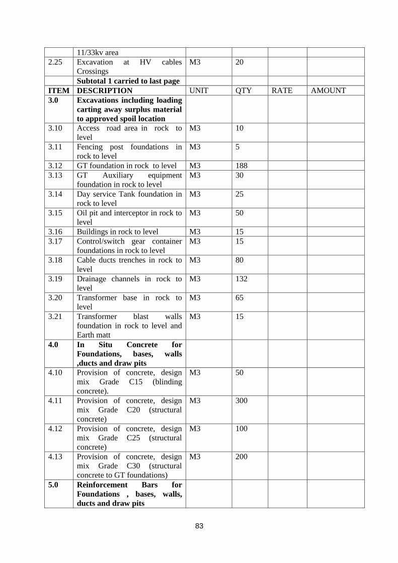
83
11/33kv area
2.25 Excavation at HV cables
Crossings
M3 20
Subtotal 1 carried to last page
ITEM DESCRIPTION UNIT QTY RATE AMOUNT
3.0 Excavations including loading
carting away surplus material
to approved spoil location
3.10 Access road area in rock to
level
M3 10
3.11 Fencing post foundations in
rock to level
M3 5
3.12 GT foundation in rock to level M3 188
3.13 GT Auxiliary equipment
foundation in rock to level
M3 30
3.14 Day service Tank foundation in
rock to level
M3 25
3.15 Oil pit and interceptor in rock to
level
M3 50
3.16 Buildings in rock to level M3 15
3.17 Control/switch gear container
foundations in rock to level
M3 15
3.18 Cable ducts trenches in rock to
level
M3 80
3.19 Drainage channels in rock to
level
M3 132
3.20 Transformer base in rock to
level
M3 65
3.21 Transformer blast walls
foundation in rock to level and
Earth matt
M3 15
4.0 In Situ Concrete for
Foundations, bases, walls
,ducts and draw pits
4.10 Provision of concrete, design
mix Grade C15 (blinding
concrete).
M3 50
4.11 Provision of concrete, design
mix Grade C20 (structural
concrete)
M3 300
4.12 Provision of concrete, design
mix Grade C25 (structural
concrete)
M3 100
4.13 Provision of concrete, design
mix Grade C30 (structural
concrete to GT foundations)
M3 200
5.0 Reinforcement Bars for
Foundations , bases, walls,
ducts and draw pits

84
5.10 BRC A142 mesh Kg 1000
5.10 Reinforcement; Deformed high
yield steel bars to BS4449;
Nominal size 8mm.
kg 3700
5.11 Reinforcement; Deformed high
yield steel bars to BS4449;
Nominal size 10mm.
kg 5820
5.12 Reinforcement; Deformed high
yield steel bars to BS4449;
Nominal size 12mm.
kg 9347
5.13 Reinforcement; Deformed high
yield steel bars to BS4449;
Nominal size 16mm.
kg 8613
5.14 Reinforcement; Deformed high
yield steel bars to BS4449;
Nominal size 20mm
kg 2230
5.15 Reinforcement; Deformed high
yield steel bars to BS4449;
Nominal size 25mm
kg 6500
Sub total 2 carried to last page
ITEM DESCRIPTION UNIT QTY RATE AMOUNT
6.0 Formwork for foundations,
bases, walls , ducts and draw
pits
6.10 Formwork; F1 finish; plane
vertical.
M2 750
6.11 Formwork;F1 finish; horizontal M2 300
6.12 Formwork; to edges and corners
(chamfers)
Sum
7.0 Form pockets for , and grout
in, imbedded parts holding
down bolts, plates (to be
supplied by others):
7.10 Holding down bolts Sum
7.11 Imbedded plates Sum
7.12 Allow for grouting Sum
8.0 Buried ducts in foundations
8.10 Supply and install 150mm dia.
Class E UPVC pipes
M 500
9.0 Service Tank
Bundwalling/Fuel interceptor
9.10 20mm Walling to service tank
bundwall
M2 70
9.11 2 layers of flat bars at every
course
Kg 25
9.11 Rendering internal and external M2 140
9.12 100mm diameter GI pipework
connection to interceptor
M 12

85
9.13 Allow for bends , valves and
fittings for the above
Sum
9.14 Allow for inspection,
connection manholes from
bundwall to interceptor.
No. 5
9.15 Manhole covers to interceptor No. 5
9.16 Drain pipe 150mm diameter GI
complete with valve
Sum
10.0 Transformer Foundations
/Fuel interceptor
10.10 125mmHDPE drain pipes to
detail
M 10
10.11 100mmHDPE drain pipes to
detail
M 12
10.12 200mmHDPE drain pipes to
detail
M 18
10.13 200mm HDPE connection to
interceptor tank complete with
fittings
M 12
10.14 Jacking plates to detail Sum
10.15 Transformer gratings to detail Sum
10.16 Gratings support to detail Sum
10.17 Gravel and crushed stone on
grating to detail
Sum
11.0 Chain-link fencing
11.10 Supply and place vibrated
reinforced cranked concrete
fencing posts size 125mm by
125mm by 2400mm to be
1800mm above the ground at a
spacing of 3m.
No. 150
11.11 Supply and install single
straight struts at all corners and
double straight struts at a
spacing of 50m. Size 125mm X
125mm X 2,000mm.
No. 20
Subtotal 3 carried to last page
ITEM DESCRIPTION UNIT
QTY RAT
E
AMOUNT
11.12 Supply and fix straining wire
gauge 8 in three lines (Top,
centre and bottom)
M 2190
11,13 Supply and fix chain link fence
gauge 10, 1800mm high firmly
secured with binding wire to the
straining wire and anchored on
the ground by 300mmx300mm
concrete (C20) along the entire
M2 1330

86
length
11.14 Removal of existing chain link
and straining wire , replacement
covered under item 11.12-11.13
Sum
11.14 Steel gates to fencing ( double
leaf 6m wide supported on RC
columns with pedestrian gate)
No.
1
12.0 Access Road
12.10 Supply and compaction of
crushed stone materials for sub
base
M3 740
12.11 Supply and compaction of
granular materials for base and
wearing course.
M3 370
12.12 Allow for side drains to falls
towards the drain.
Sum
12.13 Crossing culvert 900mm
diameter complete with
installation and Construction
wing walls
M 15
13 Drainage works ( Peripheral
drains)
13.10 Supply materials and stone
pitch the bottom and sides open
drain to falls of size
1000x1000x500mm
M 400
13.11 Supply and install invert blocks
(IB) drains. M 100
13.12 200mm dia upvc drain pipes M 50
13.13 Supply materials and stone
pitch the slopping sides of the
excavated areas.
M2 200
14.0 Transformer Blast wall
14.10 Precast light weight concrete
panels to detail No. 33
14.11 152x152x37 UC welded to base
plate to detail No. 4
14.12 350x350x35 base plate to detail No. 4
14.13 20mm dia HD bolts complete
with nuts washers,75x75 MS
end plates sleeved in 50dia
HDPE to detail
No. 24
15.0 Gravel/crushed stone levelling
15.10 Level and compact areas around
the plant as directed to receive
crushed gravel stones.
M2 1000
15.11 Supply crushed grave stones
(50-70mm) and spread at the
areas directed to average depth
M2 1000
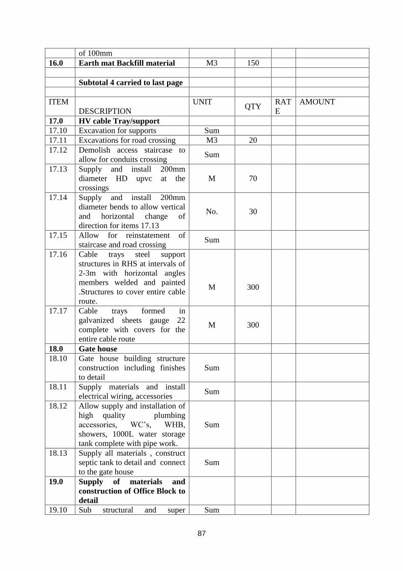
87
of 100mm
16.0 Earth mat Backfill material M3 150
Subtotal 4 carried to last page
ITEM
DESCRIPTION
UNIT
QTY
RAT
E
AMOUNT
17.0 HV cable Tray/support
17.10 Excavation for supports Sum
17.11 Excavations for road crossing M3 20
17.12 Demolish access staircase to
allow for conduits crossing Sum
17.13 Supply and install 200mm
diameter HD upvc at the
crossings
M 70
17.14 Supply and install 200mm
diameter bends to allow vertical
and horizontal change of
direction for items 17.13
No. 30
17.15 Allow for reinstatement of
staircase and road crossing Sum
17.16 Cable trays steel support
structures in RHS at intervals of
2-3m with horizontal angles
members welded and painted
.Structures to cover entire cable
route.
M
300
17.17 Cable trays formed in
galvanized sheets gauge 22
complete with covers for the
entire cable route
M 300
18.0 Gate house
18.10 Gate house building structure
construction including finishes
to detail
Sum
18.11 Supply materials and install
electrical wiring, accessories Sum
18.12 Allow supply and installation of
high quality plumbing
accessories, WC’s, WHB,
showers, 1000L water storage
tank complete with pipe work.
Sum
18.13 Supply all materials , construct
septic tank to detail and connect
to the gate house
Sum
19.0 Supply of materials and
construction of Office Block to
detail
19.10 Sub structural and super Sum

88
structural works
19.11 Roofing structure using timber,
G28 pre coated sheets Sum
19.12 Finishes, painting/decorations,
floor/wall tilling, ceiling, high
quality WC’s WHB’s urinals
showers, iron monger and
joinery works.
Sum
19.13 Aluminum framed windows,
steel external doors, Sum
19.14 Plumbing works complete with
internal water supply network Sum
19.15 Supply of materials ( pipe PPR
type, fittings ) and lay a line
from the existing bore hole
tanks to office block
M 200
19.16 Supply materials and install all
the electrical fittings and
accessories.
Sum
Subtotal 5 carried to last page
ITEM
DESCRIPTION
UNIT
QTY
RAT
E
AMOUNT
19.17 Connection to power supply
point provided by client Sum
19.18 Supply materials and connect
waste water to existing septic
tank, cost to include pipework,
excavations, manholes
Sum
19.19 External paving Sum
20.0 Supply of materials and
construction of store to detail
20.10 Sub structural and super
structural works Sum
20.11 Roofing structure using , G28
pre coated sheets Sum
20.12 Walls cladding Sum
20.13 Ventilations Sum
20.14 Steel doors to detail Sum
20.15 Finishes to detail Sum
20.16 External paving Sum
21 Access to Embakasi site
21.10 Allow for preparation of access
road to site . Sum
21.11 Allow for demolition of section
of boundary wall for access to
site
Sum
21.12 Allow for reinstatement of the Sum

89
boundary wall .
Subtotal 6
Subtotal 5
Subtotal 4
Subtotal 3
Subtotal 2
Subtotal 1
Total civils carried to
Summary
ITEM SUMMARY OF PRICES Price
(State currency OF
Tender)
1 Relocation
2 Services
3 Supply of Goods
4 Civil Works
Grand Total

90
SCHEDULE OF RATES FOR
CONSTRUCTION OF PLATFORMS
FOR GAS TURBINE (INCLUSIVE OF
VAT)
LABOUR
ITEM TRADE UNIT (KSHS)
1 Manager Hour
2 Senior Supervisor Hour
3 Foreman Hour
4 Masons/Carpenter/Steel Fixer Hour
5 Small Plant Operators Hour
6 Heavy Plant operators Hour
7 Jackhammer operators -27 Kilos and over Hour
8 Drivers Hour
9 Labourer Hour
EQUIPMENT
ITEM DESCRIPTION
1 Excavators Hour
2 Small hand Propelled Roller/Plate
Compactor
Hour
3 Vibratory Roller Hour
4 JCB Hour
5 Shovel Hour
6 Tipper Truck Hour
7 Compressor Hour
8 Truck Mixer Hour
9 Concrete Vibrator (Poker Type) Hour
10 Pick Up Hour
11 Water Tanker Hour
12 Lorry 7 Ton Hour
Note: Rates should include 16% VAT

91
SCHEDULE OF RATES FOR CONSTRUCTION OF PLATFORMS FOR GAS
TURBINE (INCLUSIVE OF VAT)
LABOUR
ITEM TRADE UNIT (state currency)
1 Manager Hour
2 Senior Supervisor Hour
3 Foreman Hour
4 Masons/Carpenter/Steel Fixer Hour
5 Small Plant Operators Hour
6 Heavy Plant operators Hour
7 Jackhammer operators -27 kilos and over Hour
8 Drivers Hour
9 Labourer Hour
EQUIPMENT
ITEM DESCRIPTION
1 Excavators Hour
2 Small hand Propelled Roller/Plate Compactor Hour
3 Vibratory Roller Hour
4 JCB Hour
5 Shovel Hour
6 Tipper Truck Hour
7 Compressor Hour
8 Truck Mixer Hour
9 Concrete Vibrator (Poker Type) Hour
10 Pick Up Hour
11 Water Tanker Hour
12 Lorry 7 Ton Hour
Note: Rates should include 16% VAT

92
SECTION VII
TENDER FORM
Date: _______________________
To: Company Secretary &Legal Affairs Director
Kenya Electricity Generating Company Limited
10th Floor, KenGen Pension Plaza 2,
P. O. Box 47936-00100
NAIROBI, KENYA.
Gentlemen and/or Ladies:
1. Having examined the tender documents including Addenda no.s……….…………
the receipt of which is hereby duly acknowledged, we, the undersigned, offer to supply Services of
Relocation of two GE Frame 6 Gas Turbine Plants Embakasi to Muhoroni site in conformity with
the said tender documents for the sum
Of………………………………………………………………………………………….
[Total tender amount in words and figures]
or such other sums as may be ascertained in accordance with the Schedule of Prices attached herewith
and made part of this Tender.
2. We undertake, if our Tender is accepted, to deliver the goods in accordance with the delivery
schedule specified in the Schedule of Requirements.
3. If our Tender is accepted, we will obtain the guarantee of a bank in a sum equivalent to 10% percent
of the Contract Price for the due performance of the Contract, in the form prescribed by Kenya
Electricity Generating Company Limited.
4. We agree to abide by this Tender for a period of 120 days from the date fixed for tender opening of
the Instructions to Contractors, and it shall remain binding upon us and may be accepted at any time
before the expiration of that period.
5. Until a formal Contract is prepared and executed, this Tender, together with your written acceptance
thereof and your notification of award shall constitute a binding Contract between us.
6. We understand that you are not bound to accept the lowest or any tender you may receive.
7. We hereby declare that we have not been debarred from any procurement process and
Shall not engage in any fraudulent or corrupt act with regard to this purchase.
Dated this ________________ day of ________________ 2017.

93
[Signature] [In the capacity of]
Duly authorized to sign tender for and on behalf of
SECTION VIII
TENDER SECURITY FORM
(To be on Bank’s Letterhead)
Whereas………………………………………. [Name of the contractors]
(hereinafter called “the contractors”) has submitted its tender dated ………………..[date of submission
of tender] for the Services of Relocation of two GE Frame 6 Gas Turbine Plants from Embakasi
to Muhoroni site(hereinafter called “the Tender”)………….………………………………………
KNOW ALL PEOPLE by these presents that WE…….……………………………………… Of…………………………………………………….. Having our registered office at ……………………… (Hereinafter called “the Bank”), are bound
unto Kenya Electricity Generating Company (KenGen. hereinafter called “the Procuring entity”) in the sum of ……………………………………………………
For which payment well and truly to be made to the said Procuring entity, the Bank binds itself, its
successors, and assigns by these presents. Sealed with the Common Seal of the said Bank this _____
day of _________2017.
THE CONDITIONS of this obligation are:
1. If the contractors withdraws its Tender during the period of tender validity specified by the
contractors on the Tender Form; or
2. If the contractors, having been notified of the acceptance of its Tender by the Procuring entity
during the period of tender validity:
(a) Fails or refuses to execute the Contract Form, if required; or
(b) Fails or refuses to furnish the performance security, in accordance with the Instructions to
Contractors;
We undertake to pay to the Procuring entity up to the above amount upon receipt of its first written
demand, without the Procuring entity having to substantiate its demand, provided that in its demand the
Procuring entity will note that the amount claimed by it is due to it, owing to the occurrence of one or
both of the two conditions, specifying the occurred condition or conditions.
This guarantee will remain in force up to and including thirty (30) days after the period of tender
validity, and any demand in respect thereof should reach the Bank not later than the above date.

94
[Signature of the bank]
SECTION IX
CONTRACT FORM
THIS AGREEMENT made the _____ day of __________ 2017 between Kenya Electricity
Generating Company Limited of Kenya (hereinafter called “the Procuring entity”) of the one part
and………………………… of…………. [City and country of contractors] (Hereinafter called “the
contractors”) of the other part:
WHEREAS the Procuring entity invited tenders for certain goods, viz the Services of Relocation of
two GE Frame 6 Gas Turbine Plants from Embakasi to Muhoroni site And has accepted a tender by the contractors for the supply of those goods in the sum
of………………………………………………… [Contract price in words and figures] (Hereinafter
called “the Contract Price”).
NOW THIS AGREEMENT WITNESSETH AS FOLLOWS:
1. In this Agreement words and expressions shall have the same meanings as are respectively
assigned to them in the Conditions of Contract referred to.
1. The following documents shall be deemed to form and be read and construed as part of this
Agreement, viz.:
(A) THE TENDER FORM AND THE PRICE SCHEDULE SUBMITTED BY THE
CONTRACTORS;
(B) THE SCHEDULE OF REQUIREMENTS;
(C) THE TECHNICAL SPECIFICATIONS;
(D) THE CONDITIONS OF CONTRACT;
(E) THE SPECIAL CONDITIONS OF CONTRACT IF ANY; AND
(F) THE PROCURING ENTITY’S NOTIFICATION OF AWARD.
3. In consideration of the payments to be made by the Procuring entity to the contractors as
hereinafter mentioned, the contractors hereby covenants with the Procuring entity to provide the
goods and to remedy defects therein in conformity in all respects with the provisions of the
Contract
4. The Procuring entity hereby covenants to pay the contractors in consideration of the provision
of the goods and the remedying of defects therein, the Contract Price or such other sum as may
become payable under the provisions of the contract at the times and in the manner prescribed
by the contract.

95
IN WITNESS whereof the parties hereto have caused this Agreement to be executed in accordance with
their respective laws the day and year first above written.
Signed, sealed, delivered by the ________ (for the Procuring entity)
Signed, sealed, delivered by the (for the contractors)
In the presence of______________

96

97
SECTION X
PERFORMANCE SECURITY FORM
To: Company Secretary &Legal Affairs Director
Kenya Electricity Generating Company Limited
10th Floor, KenGen Pension Plaza 2,
P.O. Box 47936-00100
NAIROBI, KENYA
WHEREAS ………………………………….….. [Name of contractors]
(Hereinafter called “the contractors”) has undertaken, in pursuance of Contract
No.____________ [reference number of the contract] dated ____________ 2017 to supply
The Services of Relocation of two GE Frame 6 Gas Turbine Plants from Kipevu to Embakasi site (Hereinafter called “the Contract”).
AND WHEREAS it has been stipulated by you in the said Contract that the contractors shall furnish
you with a bank guarantee by a reputable bank for the sum specified therein as security for compliance
with the Contractors’s performance obligations in accordance with the Contract.
AND WHEREAS we have agreed to give the contractors a guarantee:
THEREFORE WE hereby affirm that we are Guarantors and responsible to you, on behalf of the
contractors, up to a total of……………………………………………………………
[amount of the guarantee in words and figures], and we undertake to pay you, upon your first written
demand declaring the contractors to be in default under the Contract and without cavil or argument, any
sum or sums within the limits of……………………………………
[Amount of guarantee] as aforesaid, without your needing to prove or to show grounds or reasons for
your demand or the sum specified therein.
This guarantee is valid until the _____ day of __________2017.
Signature and seal of the Guarantors
[Name of bank or financial institution]
[Address]

98
[Date]
N/B This performance security should be in the letterhead of the guaranteeing Bank

99
SECTION XI
MANDATORY CONFIDENTIAL BUSINESS QUESTIONNAIRE
(Must be filled by all applicants or renderers’ who choose to participate in this tender)
Name of Applicant (S)
……………………………………………………………………………………………………………
………….
You are requested to give the particulars in Part 1 and either Part 2 (a), 2 (b) or 2 (c), whichever applies
to your type of business. Part 2 (d) to part 2(i) must be filled.
You are advised that giving wrong or false information on this Form will lead to automatic
disqualification / termination of your business proposal at your cost.
Part 1 – General
Business Name:
Certificate of Incorporation / Registration No.
……………………………………………………………….
Location of business premises: Country
…………………………………..……….…………….
Physical address …………………………….Town
………………………………….……………………….
Building………………………………
Floor…………………………………………………………….
Plot No. …………………………………………….Street / Road
……..………………….……………………
Postal Address …………………………………Postal / Country
Code…………………………………….
Telephone No’s ……………………………………………… Fax No’s.
……………………….………………
E-mail address
…………………………………………………………………………………………………………
Website ………………………………………………………………………………………
Contact Person (Full Names) …………………………… Direct / Mobile No’s. ………………..…
Title ……………………………………… Power of Attorney (Yes / No) If Yes, attach written
document.
Nature of Business (Indicate whether manufacturer, distributor, etc) ………………..……….………..
(Applicable to Local suppliers only)
Local Authority Trading License No. …………………… Expiry Date
……………………………………..
Value Added Tax
No.…………………………………………….……………………………………………….
Value of the largest single assignment you have undertaken to date (US$/KShs) …………
Was this successfully undertaken? Yes / No. …………………………. (If yes, attach reference)
Name (s) of your banker (s)
………………………………………………………………………..……………..

100
Branches …………………………………………………………. Tel No’s.
……….………………………….
Part 2 (a) – Sole Proprietor
Full names
……..………………………………………..………………………………..……………………….
Nationality ……………………………………………….. Country of Origin
…………....…………………..
*Citizenship details
……………………………………………………………………..……..………………….
Company Profile ………………………. (Attach brochures or annual reports in case of public
companies)
Part 2 (b) – Partnerships
Give details of partners as follows:
Full Names Nationality Citizenship Details Shares
1. …………………………. ………………… ………………………….
……..…….
2. ………………………… ………………… ………………………….
………..…..
3.………………………… ………………… …………………………..
………….…
4………………………… ………………… ………………………….
……….……
Company Profile ……………………….(Attach brochures)
Part 2 (c) – Registered Company
Private or public …………………………………………….
Company Profile ……………………….(Attach brochures or annual reports in case of public
companies)
State the nominal and issued capital of the Company
Nominal KShs ……………………..………………………….
Issued KShs ………………………..………………………….
List of top ten (10) shareholders and distribution of shareholding in the company.
Give details of all directors as follows:-
Full Names Nationality Citizenship Details Shares
1.…………………………. ……………… …………………… ……….…….
2………………………… ………………… …………………. ……..…..…..
3………………………… ………………… ………………… ……..…..…..
4………………………… ………………… ………………… ………....…..
Part 2 (d) – Debarment

101
I/We declare that I/We have not been debarred from any procurement process and shall not engage in
any fraudulent or corrupt acts with regard to this or any other tender by KenGen and any other public or
private institutions.
Full Names
……………………………………………………………………………………………………………
…..
Signature
………………………………………………………………………………………………………….
Dated this …………………………………….……………day of
…………………………………………2017.
In the capacity of
………………………………………………………………………………………………………
Duly authorized to sign Tender for and on behalf of …………………………………………………
Part 2 (e) – Criminal Offence
I/We, (Name (s) of Director (s)):-
a) ……………………………………………………………………….………..………………
………
b) …………………………………………………………………………..….……….…………
……
c) …………………………………………………………………………………………………
……
d) …………………………………………………………………………………………………
…
have not been convicted of any criminal offence relating to professional conduct or the making of false
statements or misrepresentations as to its qualifications to enter into a procurement contract within a
period of three (3) years preceding the commencement of procurement proceedings.
Signed
…………………………………………………………………………………………………………….
…………
For and on behalf of M/s
…………………………………………………………………………………………..
In the capacity of
…………………………………………………………………………………………………
Dated this ……………………………………………day of
…………………………………………….2017.
Suppliers’ / Company’s Official Rubber Stamp ………………………………………………………….
Part 2 (f) – Conflict of Interest
I/We, the undersigned state that I / We have no conflict of interest in relation to this procurement:
a) …………………………………………………………………………………………………
…
b) …………………………………………………………………………………………………
……
c) …………………………………………………………………………………………………
……

102
d) …………………………………………………………………………………………………
…………
For and on behalf of M/s
…………………………………………………………………………………..
In the capacity of
……………………………………………………………………………………………….
Dated this ……………………………………………day of
…………………………………………….2017.
Suppliers’ / Company’s Official Rubber Stamp ………………………………………………………….
Part 2 (g) – Interest in the Firm:
Is there any person / persons in KenGen or any other public institution who has interest in the Firm?
Yes / No? ……………………….. (Delete as necessary) Institution ………………………….
……………………………………. ……………………………… ………………………
(Title) (Signature) (Date)
Part 2(h) – Experience
Please list here below similar projects accomplished or companies / clients you have supplied with
similar items or equipments in the last two (2) years.
Company Name Country Contract/ Order No. Value
1.…………………………. ………………… ………………………. ……..…….
2. ………………………… ………………… …………………………. ………..…..
3.………………………… ………………… …………………………. ………..…..
Contact person (Full Names) ……………………………. E-mail address………………………….
Cell phone no …………………………. (Note: The person should be at the level of director)
*Attach proof of citizenship
* Attach certified copies of the following documents:
a) Previous orders from companies supplied before
b) Certificate of Incorporation / Registration
c) Tax Compliance Certificate (for local suppliers)
d) VAT Certificate (for local suppliers)
e) Audited Financial Statements / Accounts for the last two (2) years
f) Valid Local Authority / Trade License (for local suppliers)
g) The Power of Attorney for a joint venture
*The above documents should be submitted if they are applicable to bidder.
Part 2(i) – Declaration
I / We, the undersigned state and declare that the above information is correct and that I / We give
Kenya Electricity Generating Company Limited authority to seek any other references concerning my /

103
our company from whatever sources deemed relevant, e.g. Office of the Registrar of Companies,
Bankers, etc.
Full names
…………………………………………………………………………………………………………..
Signature…………………………………………………………………………………………………
….………
For and on behalf of M/s
…………………………………………………………………………………………..
In the capacity of
…………………………………………………………………………………………………
Dated this ……………………………………………day of
…………………………………………….2017.
Suppliers’ / Company’s Official Rubber Stamp ………………

104
SECTION XII
QUALIFICATION INFORMATION
FORMAT FOR CURRICULUM VITAE (CV) KEY STAFF TO BE
COMPLETED FOR FIVE (5) KEY STAFF
Part A: Employee Personal Details
Name of Firm:
Department
Year of
employment
No. of
Years
with
Firm
Employee Name: Profession: Current Position: Reports to (Position): Tasks assigned:
Part B: Educational Background Date School / Institution or College Course studied Qualification / Certificate
Obtained
Part C: Professional Affiliations
Part D: Relevant Trainings attended Date Description Certificate Obtained
Part E: Work Experience / Employment Record
Date Organization Position Major Achievements

Detailed Tasks Assigned:……………….………………………………………...
Key Qualifications:
(Give an outline of staff member’s experience and training most pertinent to tasks
on assignment. Describe degree of responsibility held by staff member on relevant
previous assignments and give dates and locations.)
Education:
(Summarize University/College and other specialized education of staff member,
giving names of schools, dates attended and degrees/diplomas obtained)
Employment record:
(Starting with present position, list in reverse order every employment held. List
all positions held by staff since graduation, giving dates, names of employing
organization, title of position held and location of assignments. For experience in the
last ten years, also give types of activities performed and Employer references, where
appropriate).
Languages:
(Indicate proficiency in speaking, reading and writing of each language: excellent, good,
fair or poor).
Certification / Declaration.
I, the undersigned, certify that to the best of my knowledge and belief, these bio data
correctly describe me, my qualifications and experience.
Signed…………………………………………………………………
…… (Signature of staff member of authorized official from firm)
Date………………………………………………………………………

Fig 1: Single Line Drawing Illustrating Position of New Tariff Metering and Protection
Current Transformer

SECTION XIII-TENDER QUESTIONNAIRE
Please fill in block letters.
1. Full names of Tenderer
………………………………………………………………………………………
2. Full address of Tenderer to which tender correspondence is to be sent (unless an agent
has been appointed below)
………………………………………………………………………………………
3. Telephone number (s) of Tenderer
………………………………………………………………………………………
4. E-mail and Fax address of Tenderer
………………………………………………………………………………………
5. Name of Tenderer’s representative to be contacted on matters of the tender during the
tender period
………………………………………………………………………………………
6. Details of Tenderer’s nominated agent (if any) to receive tender notices. This is essential
if the Tenderer does not have his registered address in Kenya (name, address, telephone,
e-mail)
………………………………………………………………………………………
………………………………………………………………………………………
_________________
Signature of Tenderer
Make copy and deliver to: ___________________________ (Name of Employer
Related Documents