REPUBLIC OF KENYA COUNTY GOVERNMENT OF KIAMBU DIRECTORATE OF PUBLIC WORKS PROPOSED FUNERAL HOME AT GATUNDU LEVEL V HOSPITAL TENDER No.KCG/CHS/007/2017/2018 TENDER DOCUMENT FOR SUPPLY, DELIVERY, INSTALLATION, TESTING AND COMMISSIONING OF MECHANICAL WORKS ISSUED BY PREPARED BY DIRECTOR, PUBLIC WORKS COUNTY QUANTITY SURVEYOR KIAMBU COUNTY KIAMBU COUNTY P.O.BOX 189-00900 P.O. BOX 189-00900 KIAMBU KIAMBU COUNTY MECHANICAL ENGINEER KIAMBU COUNTY P.O. BOX 189-00900 KIAMBU APRIL 2018

Welcome message from author
This document is posted to help you gain knowledge. Please leave a comment to let me know what you think about it! Share it to your friends and learn new things together.
Transcript

REPUBLIC OF KENYA
COUNTY GOVERNMENT OF KIAMBU
DIRECTORATE OF PUBLIC WORKS
PROPOSED FUNERAL HOME AT GATUNDU LEVEL V HOSPITAL
TENDER No.KCG/CHS/007/2017/2018
TENDER DOCUMENT
FOR
SUPPLY, DELIVERY, INSTALLATION, TESTING AND
COMMISSIONING OF MECHANICAL WORKS
ISSUED BY PREPARED BY
DIRECTOR, PUBLIC WORKS COUNTY QUANTITY SURVEYOR
KIAMBU COUNTY KIAMBU COUNTY
P.O.BOX 189-00900 P.O. BOX 189-00900
KIAMBU KIAMBU
COUNTY MECHANICAL ENGINEER
KIAMBU COUNTY
P.O. BOX 189-00900
KIAMBU
APRIL 2018

TABLE OF CONTENTS CONTENTS PAGE
CONTENTS PAGE……………………………………………………….. (i)
DEFINITIONS……………………………………………………………. (ii)
SPECIAL NOTES……………………………………………………….... (iii)
FORM OF TENDER………………………………………………………. [iv-v]
FORM OF BID SECURITY………………………………………………... [vi-vii}
SECTION A: INSTRUCTIONS TO TENDERERS……………………….. A-1 to A-23
SECTION B: CONDITIONS OF CONTRACT (MAIN WORKS) B-1 to B-11
SUB-CONTRACT AGREEMENT FORM- KABCEC……………………… 1 - 22
SECTION C: SUB CONTRACTS PRELIMINARIES AND GENERAL
CONDITIONS……………………………………….…… C-1 to C-21
SECTION D: GENERAL MECHANICAL SPECIFICATION…………….. D-1 to D-4
SECTION E: PARTICULAR SPECIFICATIONS FOR MECHANICAL
VENTILATION AND AIR CONDITIONING………….… E-1 to E-13
SECTION F: PARTICULAR SPECIFICATIONS FOR MORTUARY
COLD ROOMS …………………………………………..… F-1 to F-5
SECTION G: BILLS OF QUANTITIES AND SCHEDULE OF
UNITS RATES ………………………………………….. G-1 to G-25
SECTION I: TECHNICAL SCHEDULE OF ITEMS TO BE
SUPPLIED ……………………………………………….. H-1 to H-2
SECTION I: STANDARD FORMS…………………………………………. I-1 to I-13
(i)

DEFINITIONS
The following terms and expressions used in the contract document shall have the following meanings:
The Employer Kiambu County Government
Represented by:
County Secretary,
P.O. Box 2344-00900,
KIAMBU
Architect Kiambu County Architect
P.O. Box 189-00900,
KIAMBU
Engineer (Mechanical) Kiambu County Mechanical Engineer
P.O. Box 189-00900,
KIAMBU
Engineer (Electrical) Kiambu County Electrical Engineer
P.O. Box 189-00900,
KIAMBU
Quantity Surveyor Kiambu County Quantity Surveyor
P.O. Box 189-00900,
KIAMBU
Structural Engineer Kiambu County Structural Engineer
P.O. Box 189-00900,
KIAMBU
Site Location The site is located at Gatundu Town, in Kiambu County.
(ii)

SPECIAL NOTES
1. These notes shall form part of the Instructions to Tenderers and Conditions of Contract.
2. The Tenderer is required to check the number of pages in this document and should he find any
missing, or in duplicate, or indistinct he should inform the Kiambu County Mechanical Engineer.
3. Should the Tenderer be in any doubt about the precise meaning of any item or figure, for any reason
whatsoever, he must inform the Kiambu County Mechanical Engineer, in order that the correct
meaning may be decided before the date of submission of tender.
4. No liability will be admitted nor claim allowed, in respect of errors in the tender due to mistakes in the
specification, which should have been rectified in the manner, described above.
5. All tenderers must make a declaration that they have not and will not make any payment to any person
which can be perceived as an inducement to enable them to win this tender.
6. Any Tenderer whose firm uses the titles “Engineer” and “Engineers” must produce evidence of
registration of at least one of the directors by the Engineers Board of Kenya to avoid disqualification.
(iii)

FORM OF TENDER
To: County Secretary,
Kiambu County Government,
P.O. Box 2344-00900,
Kiambu.
Dear Sir,
SUPPLY, DELIVERY, INSTALLATION AND COMMISSIONING OF MECHANICAL
WORKS AT PROPOSED FUNERAL HOME AT GATUNDU LEVEL V HOSPITAL
1. In accordance with the Instructions to Tenderers, Conditions of Contract, Specifications and
Bills of Quantities for the execution of the above named Works, we, the undersigned offer to
construct, install and complete such Works and remedy any defects therein for the sum of:
Kshs………………………………………………………………………[Amount in figures]
Kenya Shillings…………………………………………………………………………………
…………………………………………………………………………………………………
……………………………………………………………………………[Amount in words]
2. We undertake, if our tender is accepted, to commence the Works as
soon as is reasonably possible after the receipt of the Employer’s Representative’s notice to
commence, and to complete the whole of the Works comprised in the Contract within the
time stated in the Appendix to Conditions of Contract.
3. We agree to abide by this tender for a period of …………………(insert date) and shall
remain binding upon us and may be accepted at any time before that date.
4. Unless and until a formal Agreement is prepared and executed this tender together with your
written acceptance thereof, shall constitute a binding Contract between us.
(iv)

We understand that you are not bound to accept the lowest or any tender you may receive.
Dated this …………………………………..…….. day of …………………20…………..
Signature ………………….in the capacity of ………………………………………….
Duly authorized to sign tenders for and on behalf of:
…………………………………………………………………….…..[Name of Tenderer]
of…………………………………………………………………….[Address of Tenderer]
PIN No. ………………………………………………………………………..
VAT CERTIFICATE No. ……………………………………………………
Witness: Name …………………………………………………….….
Address ………………………………………………………
Signature …………………………………………………..…
(v)

FORM OF TENDER SECURITY FROM BANK
To: County Secretary,
Kiambu County Government,
P.O. Box 2344-00900,
Kiambu.
WHEREAS …………………………………(hereinafter called “the Tenderer”) has submitted his tender dated
……………………. For the Supply, Delivery, Installation, Testing and Commissioning of Mechanical
Works at Proposed Funeral Home at Gatundu Level V Hospital
KNOW ALL PEOPLE by these presents that WE ……………………………………………………….…....
Having our registered office at ………………………………………..……………………………….……….
(hereinafter called “the Bank’), are bound unto ……………………..…………………………………………
(hereinafter called “the Employer”) in the sum of Kshs…………………….……………………….…………
for which payment well and truly to be made to the said Employer, the Bank binds itself, its successors and
assigns by these presents sealed with the Common Seal of the said Bank this ………………………Day of
………………………….20 ………
THE CONDITIONS of this obligation are:
1. If after tender opening the Tenderer withdraws his tender during the period of tender validity
specified in the instructions to Tenderers
Or
2. If the Tenderer, having been notified of the acceptance of his tender by the Employer during the
period of tender validity:
(a) fails or refuses to execute the form of Agreement in accordance with the Instructions to
Tenderers, if required; or
(b) fails or refuses to furnish the Performance Security, in accordance with the Instructions to
Tenderers;
We undertake to pay to the Employer up to the above amount upon receipt of his first written
demand, without the Employer having to substantiate his demand, provided that in his demand the
Employer will note that the amount claimed by his is due to him, owing to the occurrence of one
or both of the two conditions, specifying the occurred condition or conditions.
This guarantee will remain in force up to and including One Hundred and Fifty (150) days after
the day of tender opening, and any demand in respect thereof should reach the Bank not later than
the said date.
………………………………….. ………………………………
(date) (signature of the Bank)
………………………………… ……………………………..
(witness) (seal)
(vi)

FORM OF TENDER SECURITY
(INSURANCE)
To: County Secretary,
Kiambu County Government,
P.O. Box 2344-00900,
Kiambu.
WHEREAS …………………………………(hereinafter called “the Tenderer”) has submitted his tender dated
……………………. For the Supply, Delivery, Installation, Testing and Commissioning of Mechanical
Works at Proposed Funeral Home at Gatundu Level V Hospital
KNOW ALL PEOPLE by these presents that WE...........................................................of……...(Name of
Insurance Company)
having our registered office at ...........................................................................
(hereinafter called “ the Guarantor”), are bound unto .......................................................
(hereinafter called “the Procuring Entity” in the sum of Kshs..........................................
for which payment well and truly to be made to the said Procuring Entity , the Guarantor bind itself, its
successors and assigns by these presents sealed with the Common Seal of the said Guarantor this
...........................Day of ...............20.............
THE CONDITIONS of this obligation are:
1. If after tender opening the tenderer withdraws his tender during the period of
tender validity specified in the instructions to tenderers
Or
2. If the tenderer, having been notified of the acceptance of this tender by the Employer during the
period of tender validity:
a) fails or refuses to execute the form of Agreement in accordance with the
Instructions to Tenderers, if required; or
b) fails or refuses to furnish the Performance Security, in accordance with the
Instructions to Tenderers;
We undertake to pay to the Employer up to the above amount upon receipt of his first written demand, without
the Employer having to substantiate his demand, provided that in his demand the Employer will note that the
amount claimed by him is due to him, owing to the occurrence of one or both of the two conditions, specifying
the occurred condition or conditions.
This guarantee will remain in force for a period of 150 days from the date of tender opening, and any demand
in respect thereof should reach the Guarantor not later than the said date.
_______________________________ ______________________________
[date] [signature of the Guarantor]
______________________________ ___________________________
[witness] [seal]
(vii)

SECTION A
INSTRUCTION TO TENDERERS

i
INSTRUCTION TO TENDERERS
CONTENTS
CLAUSE DESCRIPTION PAGE
1. Definitions .................................................................................................................... A-3
2. Eligibility and Qualification Requirements.................................................................. A-3
3. Cost of Tendering ......................................................................................................... A-4
4. Site Visit ....................................................................................................................... A-4
5. Tender Documents ....................................................................................................... A-5
6. Clarification of Tender Documents .............................................................................. A-6
7. Amendment of Tender Documents .............................................................................. A-6
8. Language of Tender ..................................................................................................... A-6
9. Documents Comprising the Tender ............................................................................. A-7
10. Tender Prices ................................................................................................................ A-7
11. Currencies of Tender and Payment .............................................................................. A-8
12. Tender Validity ............................................................................................................ A-8
13. Tender Surety ............................................................................................................... A-8
14. No Alternative Offers ................................................................................................... A-9
15. Pre-Tender Meeting.................................................................................................... A-10
16. Format and Signing of Tenders .................................................................................. A-10
17. Sealing and Marking of Tenders ................................................................................ A-11
18. Deadline for Submission of Tenders .......................................................................... A-11
19. Modification and Withdrawal of Tenders .................................................................. A-11
20. Tender Opening .......................................................................................................... A-12
21. Process to be Confidential .......................................................................................... A-13
22. Clarification of Tenders ............................................................................................. A-13
23. Determination of Responsiveness .............................................................................. A-13
24. Correction of Errors ................................................................................................... A-14
25. Conversion to Single Currency .................................................................................. A-14
26. Evaluation and Comparison of Tenders ..................................................................... A-14
27. Award ......................................................................................................................... A-15
ii
28. Notification of Award ................................................................................................ A-15
29. Performance Guarantee .............................................................................................. A-16
30. Advance Payment ....................................................................................................... A-16

3
INSTRUCTION TO TENDERERS
Note: The Tenderer must comply with the following conditions and instructions and failure to do so is liable
to result in rejection of the tender.
GENERAL
Definitions
(a) “Tenderer” means any person or persons partnership firm or company submitting a sum or
sums in the Bills of Quantities in accordance with the Instructions to Tenderers, Conditions of
Contract Parts I and II, Specifications, Drawings and Bills of Quantities for the work
contemplated, acting directly or through a legally appointed representative.
(b) “Approved Tenderer” means the Tenderer who is approved by the Employer.
(c) Any noun or adjective derived from the word “tender” shall be read and construed to mean
the corresponding form of the noun or adjective “bid”. Any conjugation of the verb “tender”
shall be read and construed to mean the corresponding form of the verb “bid.”
(d) “Employer” means a Central Government Ministry, County Government, State Corporation
or any other Public Institution.
Eligibility and Qualification Requirements
2.1 This invitation to tender is open to all tenderers who have been pre-qualified.
2.2 To be eligible for award of Contract, the Tenderer shall provide evidence satisfactory to the
Employer of their eligibility under Sub clause 2.1 above and of their capability and adequacy of
resources to effectively carry out the subject Contract. To this end, the Tenderer shall be
required to update the following information already submitted during pre-qualification: -
(a) Details of experience and past performance of the Tenderer on the works of a similar
nature within the past five years and details of current work on hand and other
contractual commitments.
(b) The qualifications and experience of key personnel proposed for administration and
execution of the contract, both on and off site.
(c) Major items of construction plant and equipment proposed for use in carrying out the
Contract. Only reliable plant in good working order and suitable for the work
required of it shall be shown on this schedule. The Tenderer will also indicate on
this schedule when each item will be available on the Works. Included also should be
a schedule of plant, equipment and material to be imported for the purpose of the
Contract, giving details of make, type, origin and CIF value as appropriate.

4
(d) Details of subcontractors to whom it is proposed to sublet any portion of the Contract
and for whom authority will be requested for such subletting in accordance with
clause 4 of the Conditions of Contract.
(e) A draft Program of Works in the form of a bar chart and Schedule of Payment which
shall form part of the Contract if the tender is accepted. Any change in the Program
or Schedule shall be subjected to the approval of the Engineer.
(f) Details of any current litigation or arbitration proceedings in which the Tenderer is
involved as one of the parties.
2.2.1 Joint Ventures
Tenders submitted by a joint venture of two or more firms as partners shall comply
with the following requirements:-
(a) The tender, and in case of a successful tender, the Form of Agreement, shall be
signed so as to be legally binding on all partners.
(b) One of the partners shall be nominated as being in charge; and this authorization
shall be evidenced by submitting a power of attorney signed by legally authorized
signatories of all the partners.
(c) The partner in charge shall be authorized to incur liabilities and receive instructions
for and on behalf of any and all partners of the joint venture and the entire execution
of the Contract including payment shall be done exclusively with the partner in
charge.
(d) All partners of the joint venture shall be liable jointly and severally for the execution
of the Contract in accordance with the Contract terms, and a relevant statement to
this effect shall be included in the authorization mentioned under (b) above as well as
in the Form of Tender and the Form of Agreement (in case of a successful tender).
(e) A copy of the agreement entered into by the joint venture partners shall be submitted
with the tender.
Cost of Tendering
The tenderer shall bear all costs associated with the preparation and submission of his tender and the
Employer will in no case be responsible or liable for those costs, regardless of the conduct or outcome
of the tendering process.
Site Visit
3.1 The tenderer is advised to visit and examine the Site and its surroundings and obtain for himself
on his own responsibility, all information that may be necessary for preparing the tender and
entering into a contract. The costs of visiting the Site shall be the tenderer’s own responsibility.

5
3.2 The tenderer and any of his personnel or agents will be granted permission by the Employer to
enter upon premises and lands for the purpose of such inspection, but only upon the express
condition that the tenderer, his personnel or agents, will release and indemnify the Employer
from and against all liability in respect of, and will be responsible for personal injury (whether
fatal or otherwise), loss of or damage to property and any other loss, damage, costs and
expenses however caused, which but for the exercise of such permission, would not have arisen.
3.3 The Employer shall organize a site visit at a date to be notified. A representative of the
Employer will be available to meet the intending tenderers at the Site.
Tenderers must provide their own transport. The representative will not be available at any
other time for site inspection visits.
Each tenderer shall complete the Certificate of Tenderer’s Visit to the Site, whether he in fact
visits the Site at the time of the organized site visit or by himself at some other time.
TENDER DOCUMENTS
Tender Documents
5.1 The Tender documents comprise the documents listed herebelow and should be read together
with any Addenda issued in accordance with Clause 7 of these instructions to tenderers.
a. Form of Invitation for Tenders
b. Instructions to Tenderers
c. Form of Tender
d. Appendix to Form of Tender
e. Form of Tender Surety
f. Statement of Foreign Currency Requirements
g. Form of Performance Security
h. Form of Agreement
i. Form of Advance payment Bank Guarantee
j. Schedules of Supplementary Information
k. General Conditions of Contract – Part I
l. Conditions of Particular Application – Part II
m. Specifications
n. Bills of Quantities
o. Drawings
5.2 The tenderer is expected to examine carefully all instructions, conditions, forms, terms,
specifications and drawings in the tender documents. Failure to comply with the requirements
for tender submission will be at the tenderer’s own risk. Pursuant to clause 22 of Instructions to
Tenderers, tenders which are not substantially responsive to the requirements of the tender
documents will be rejected.

6
5.3 All recipients of the documents for the proposed Contract for the purpose of submitting a tender
(whether they submit a tender or not) shall treat the details of the documents as “private and
confidential”.
Clarification of Tender Documents
6.1 A prospective tenderer requiring any clarification of the tender documents may notify the
Employer in writing or by telex, cable or facsimile at the Employer’s mailing address indicated
in the Invitation to Tender. The Employer will respond in writing to any request for
clarification which he receives earlier than 28 days prior to the deadline for the submission of
tenders. Written copies of the Employer’s response (including the query but without identifying
the source of the inquiry) will be sent to all prospective tenderers who have purchased the
tender documents.
Amendment of Tender Documents
7.1 At any time prior to the deadline for submission of tenders the Employer may, for any reason,
whether at his own initiative or in response to a clarification requested by a prospective
tenderer, modify the tender documents by issuing Addenda.
7.2 Any Addendum will be notified in writing or by cable, telex or facsimile to all prospective
tenderers who have purchased the tender documents and will be binding upon them.
7.3 If during the period of tendering, any circular letters (tender notices) shall be issued to tenderers
by, or on behalf of, the Employer setting forth the interpretation to be paced on a part of the
tender documents or to make any change in them, such circular letters will form part of the
tender documents and it will be assumed that the Tenderer has taken account of them in
preparing his tender. The Tenderer must promptly acknowledge any circular letters h may
receive.
7.4 In order to allow prospective tenderers reasonable time in which to take the Addendum into
account in preparing their tenders, the Employer may, at his discretion, extend the deadline for
the submission of tenders.
PREPARATION OF TENDERS
Language of Tender
8.1 The tender and all correspondence and documents relating to the tender exchanged between
the Tenderer and the Employer shall be written in the English language. Supporting
documents and printed literature furnished by the Tenderer with the tender may be in another
language provided they are accompanied by an appropriate translation of pertinent passages
in the above stated language. For the purpose of interpretation of the tender, the English
language shall prevail.

7
Documents Comprising the Tender
9.1 The tender to be prepared by the Tenderer shall comprise: the Form of Tender and
Appendix thereto, a Tender Surety, the Priced Bills of Quantities and Schedules, the
information on eligibility and qualification, and any other materials required to be completed
and submitted in accordance with the Instructions to Tenderers embodied in these tender
documents. The Forms, Bills of Quantities and Schedules provided in the tender documents
shall be used without exception (subject to extensions of the schedules in the same format and
to the provisions of clause 13.2 regarding the alternative forms of Tender Surety].
Tender Prices
10.1 All the insertions made by the Tenderer shall be made in INK and the Tenderer shall
clearly form the figures. The relevant space in the Form of Tender and Bills of Quantities
shall be completed accordingly without interlineations or erasures except those necessary to
correct errors made by the Tenderer in which case the erasures and interlineations shall be
initialed by the person or persons signing the tender.
10.2 A price or rate shall be inserted by the Tenderer for every item in the Bills of Quantities
whether the quantities are stated or not items against which no rate or price is entered by the
Tenderer will not be paid for by the Employer when executed and shall be deemed covered by
the rates for other items and prices in the Bills of Quantities.
The prices and unit rates in the Bills of Quantities are to be the full [all-inclusive] value of the
work described under the items, including all costs and expenses which may be necessary and
all general risks, liabilities and obligations set forth or implied in the documents on which the
tender is based. All duties and taxes and other levies payable by the Contractor under the
Contract or for any other cause as of the date 28 days prior to the deadline for the submission of
tenders, shall be included in the rates and prices and the total tender prices submitted by the
Tenderer.
Each price or unit rate inserted in the Bills of Quantities should be a realistic estimate for
completing the activity or activities described under that particular item and the Tenderer is
advised against inserting a price or rate against any item contrary to this instruction.
Every rate entered in the Bills of Quantities, whether or not such rate be associated with a
quantity, shall form part of the Contract. The Employer shall have the right to call for any
item of work contained in the Bills of Quantities, and such items of work to be paid for at the
rate entered by the Tenderer and it is the intention of the Employer to take full advantage of
unbalanced low rates.
10.3 Unless otherwise specified the Tenderer must enter the amounts representing 10% of the sub-
total of the summary of the Bills of Quantities for Contingencies and Variation of Prices
[V.O.P.] payments in the summary sheet and add them to the sub-total to arrive at the tender
amount.

8
10.4 The Tenderer shall furnish with his tender written confirmation from his suppliers or
manufacturers of unit rates for the supply of items listed in the Conditions of Contract clause 47
where appropriate.
10.5 The rates and prices quoted by the tenderers are subject to adjustment during the performance
of the Contract only in accordance with the provisions of the Conditions of Contract. The
Tenderer shall complete the schedule of basic rates and shall submit with his tender such other
supporting information as required under clause 47 of the Conditions of Contract Part II.
Currencies of Tender and Payment
11.1 Tenders shall be priced in Kenya Shillings and the tender sum shall be in Kenya Shillings.
11.2 Tenderers are required to indicate in the Statement of Foreign Currency Requirements, which
forms part of the tender, the foreign currency required by them. Such currency should
generally be the currency of the country of the tenderer’s main office. However, if a
substantial portion of the tenderer’s expenditure under the Contract is expected to be in
countries other than his country of origin, then he may state a corresponding portion of the
contract price in the currency of those other countries. However, the foreign currency
element is to be limited to two (2) different currencies and a maximum of 30% (thirty
percent) of the Contract Price.
11.3 The rate of rates of exchange used for pricing the tender shall be selling rate or rates of the
Central Bank ruling on the date thirty (30) days before the final date for the submission of
tenders.
11.4 Tenderers must enclose with their tenders, a brief justification of the foreign currency
requirements stated in their tenders.
Tender Validity
12.1 The tender shall remain valid and open for acceptance for a period of one hundred and twenty
(120) days from the specified date of tender opening or from the extended date of tender
opening (in accordance with clause 7.4 here above) whichever is the later.
12.2 In exceptional circumstances prior to expiry of the original tender validity period, the
Employer may request the tenderer for a specified extension of the period of validity. The
request and the responses thereto shall be made in writing or by cable, telex or facsimile. A
tenderer may refuse the request without forfeiting his Tender Surety. A tenderer agreeing to the
request will not be required nor permitted to modify his tender, but will be required to extend
the validity of his Tender Surety correspondingly.
Tender Surety
13.1 The tenderer shall furnish as part of his tender, a Tender Surety in the amount stated in the
Appendix to Instructions to Tenderers.

9
13.2 The unconditional Tender Surety shall be in Kenya Shillings and be in form of a certified
cheque, a bank draft, an irrevocable letter of credit or a guarantee from a reputable Bank
approved by the Employer located in the Republic of Kenya.
The format of the Surety shall be in accordance with the sample form of Tender Surety included
in these tender documents; other formats may be permitted subject to the prior approval of the
Employer. The Tender Surety shall be valid for twenty eight (28) days beyond the tender
validity period.
13.3 Any tender not accompanied by an acceptable Tender Surety will be rejected by the Employer
as non-responsive.
13.4 The Tender Sureties of unsuccessful tenderers will be returned as promptly as possible but not
later than twenty-eight (28) days after concluding the Contract execution and after a
Performance Security has been furnished by the successful tenderer. The Tender Surety of the
successful tenderer will be returned upon the tenderer executing the Contract and furnishing the
required Performance Security.
13.5 The Tender Surety may be forfeited:
(a) if a tenderer withdraws his tender during the period of tender validity: or
(b) in the case of a successful tenderer, if he fails
(i) to sign the Agreement, or
(ii) to furnish the necessary Performance Security
(c) if a tenderer does not accept the correction of his tender price pursuant to clause 23.
No Alternative Offers
14.1 The tenderer shall submit an offer which complies fully with the requirements of the tender
documents.
Only one tender may be submitted by each tenderer either by himself or as partner in a joint
venture.
14.2 The tenderer shall not attach any conditions of his own to his tender. The tender price must be
based on the tender documents. The tenderer is not required to present alternative construction
options and he shall use without exception, the Bills of Quantities as provided, with the
amendments as notified in tender notices, if any, for the calculation of his tender price.
Any tenderer who fails to comply with this clause will be disqualified.

10
Pre-Tender Meeting
15.1 The tenderer’s designated representative is invited to attend a pre-
tender meeting, which if convened, will take place at the venue and time stated in the
Invitation to Tender. The purpose of the meeting will be to clarify issues and to answer
questions on any matter that may be raised at that stage.
15.2 The tenderer is requested as far as possible to submit any questions in writing or by cable, to
reach the Employer not later than seven days before the meeting. It may not be practicable at
the meeting to answer questions received late, but questions and responses will be transmitted
in accordance with the following:
(a) Minutes of the meeting, including the text of the questions raised and the responses
given together with any responses prepared after the meeting, will be transmitted
without delay to all purchasers of the tender documents. Any modification of the
tender documents listed in -–Clause 9 which may become necessary as a result of the
pre-tender meeting shall be made by the Employer exclusively through the issue of a
tender notice pursuant to Clause 7 and not through the minutes of the pre-tender
meeting.
(b) Non-attendance at the pre-tender meeting will not be cause for disqualification of a
bidder.
Format and Signing of Tenders
16.1 The tenderer shall prepare his tender as outlined in clause 9 above and mark appropriately one
set “ORIGINAL” and the other “COPY”.
16.2 The copy of the tender and Bills of Quantities shall be typed or written in indelible ink and
shall be signed by a person or persons duly authorized to sign on behalf of the tenderer. Proof of
authorization shall be furnished in the form of the written power of attorney which shall
accompany the tender. All pages of the tender where amendments have been made shall be
initialed by the person or persons signing the tender.
16.3 The complete tender shall be without alterations, interlineations or erasures, except as
necessary to correct errors made by the tenderer, in which case such corrections shall be
initialed by the person of persons signing the tender.

11
SUBMISSION OF TENDERS
Sealing and Marking of Tenders
16.4 The tenderer shall seal the original and copy of the tender in separated envelopes, duly
marking the envelopes as “ORIGINAL” and “COPY”. The envelopes shall then be sealed in an
outer envelope.
17.2 The inner and outer envelopes shall be addressed to the Employer at the address stated in the
Appendix to Instructions to Tenderers and bear the name and identification of the Contract
stated in the said Appendix with a warning not to open before the date and time for opening
of tenders stated in the said Appendix.
17.3 The inner envelopes shall each indicated the name and address of the Tenderer to enable the
tender to be returned unopened in case it is declared “late”, while the outer envelope shall
bear no mark indicating the identity of the Tenderer.
17.4 If the outer envelope is not sealed and marked as instructed above, the Employer will assume
no responsibility for the misplacement or premature opening of the tender. A tender opened
prematurely for this cause will be rejected by the Employer and returned to the Tenderer.
Deadline for Submission of Tenders
18.1 Tenders must be received by the Employer at the address specified in clause 17.2 and on the
date and time specified in the Letter of Invitation, subject to the provisions of clause 7.4, 18.2
and 18.3.
Tenders delivered by hand must be placed in the “tender box” provided in the office of the
Employer.
Proof of posting will not be accepted as proof of delivery and any tender delivered after the
above stipulated time, from whatever cause arising will not be considered.
18.2 The Employer may, at his discretion, extend the deadline for the submission of tenders
through the issue of an Addendum in accordance with clause 7, in which case all rights and
obligations of the Employer and the tenderers previously subject to the original deadline shall
thereafter be subject to the new deadline as extended.
18.3 Any tender received by the Employer after the prescribed deadline for submission of tender
will be returned unopened to the Tenderer.
Modification and Withdrawal of Tenders
19.1 The tenderers may modify or withdraw his tender after tender submission, provided that
written notice of the modification or withdrawal is received by the Employer prior to
prescribed deadline for submission of tenders.

12
19.2 The tenderers modification or withdrawal notice shall be prepared, sealed, marked and
dispatched in accordance with the provisions for
the submission of tenders, with the inner and outer envelopes additionally marked
“MODIFICATION” or “WITHDRAWAL” as appropriate.
19.3 No tender may be modified subsequent to the deadline for submission of tenders.
19.4 No tender may be withdrawn in the interval between the deadline for submission of tenders
and the period of tender validity specified on the tender form. Withdrawal of a tender during
this interval will result in the forfeiture of the Tender Surety.
19.5 Subsequent to the expiration of the period of tender validity prescribed by the Employer, and
the tenderer having not been notified by the Employer of the award of the Contract or the
tenderer does not intend to conform with the request of the Employer to extend the prior of
tender validity, the tenderer may withdraw his tender without risk of forfeiture of the Tender
Surety.
TENDER OPENING AND EVALUATION
Tender Opening
20.1 The Employer will open the tenders in the presence of the tenderers’ representatives who
choose to attend at the time and location indicated in the Letter of Invitation to Tender. The
tenderers’ representatives who are present shall sign a register evidencing their attendance.
20.2 Tenders for which an acceptable notice of withdrawal has been submitted, pursuant to clause
19, will not be opened. The Employer
will examine the tenders to determine whether they are complete, whether the requisite
Tender Sureties have been furnished, whether the documents have been properly signed and
whether the tenders are generally in order.
20.3 At the tender opening, the Employer will announce the tenderer’s names, total tender price,
tender price modifications and tender withdrawals, if any, the presence of the requisite Tender
Surety and such other details as the Employer, at his discretion, may consider appropriate.
No tender shall be rejected at the tender opening except for late tenders.
20.4 The Employer shall prepare minutes of the tender opening including the information
disclosed to those present.
20.5 Tenders not opened and read out a tender opening shall not be considered further for
evaluation, irrespective of the circumstances.

13
Process to be Confidential
21.1 After the public opening of tenders, information relating to the examination, clarification,
evaluation and comparisons of tenders and recommendations concerning the award of
Contract shall not be disclosed to tenderers or other persons not officially concerned with
such process until the award of Contract is announced.
21.2 Any effort by a tenderer to influence the Employer in the process of examination, evaluation
and comparison of tenders and decisions concerning award of Contract may result in the
rejection of the tenderer’s tender.
Clarification of Tenders
22.1 To assist in the examination, evaluation and comparison of tenders, the Employer may ask
tenderers individually for clarification of their tenders, including breakdown of unit prices.
The request for clarification and the response shall be in writing or by cable, facsimile or
telex, but no change in the price or substance of the tender shall be sought, offered or
permitted except as required to confirm the correction of arithmetical errors discovered by the
employer during the evaluation of the tenders in accordance with clause 24.
22.2 No Tenderer shall contact the Employer on any matter relating to his tender from the time of
the tender opening to the time the Contract is awarded. If the tenderer wishes to bring
additional information to the notice of the Employer, he shall do so in writing.
Determination of Responsiveness
23.1 Prior to the detailed evaluation of tenders, the Employer will determine whether each tender
is substantially responsive to the requirements of the tender documents.
23.2 For the purpose of this clause, a substantially responsive tender is one which conforms to all
the terms, conditions and specifications of the tender documents without material deviation or
reservation and has a valid bank guarantee. A material deviation or reservation is one which
affects in any substantial way the scope, quality, completion timing or administration of the
Works to be undertaken by the tenderer under the Contract, or which limits in any substantial
way, inconsistent with the tender documents, the Employer’s rights or the tenderers
obligations under the Contract and the rectification of which would affect unfairly the
competitive position of other tenderers who have presented substantially responsive tenders.
23.3 Each price or unit rate inserted in the Bills of Quantities shall be a realistic estimate of the
cost of completing the works described under the particular item including allowance for
overheads, profits and the like. Should a tender be seriously unbalanced in relation to the
Employer’s estimate of the works to be performed under any item or groups of items, the
tender shall be deemed not responsive.
23.4 A tender determined to be not substantially responsive will be rejected by the Employer and
may not subsequently be made responsive by the tenderer by correction of the non-
conforming deviation or reservation.

14
Correction of Errors
Tenders determined to be substantially responsive shall be
checked by the Employer for any arithmetic errors in the
computations and summations. Errors will be corrected by the
Employer as follows:
(a) Where there is a discrepancy between the amount in figures and the amount in
words, the amount in words will govern.
(b) Where there is a discrepancy between the unit rate and the line item total resulting
from multiplying the unit rate by the quantity, the unit rate as quoted will prevail,
unless in the opinion of the Employer, there is an obvious typographical error, in
which case adjustment will be made to the entry containing that error.
(c) The amount stated in the tender will be adjusted in accordance with the above
procedure for the correction of errors and, with concurrence of the Tenderer, shall be
considered as binding upon the Tenderer. If the Tenderer does not accept the
corrected amount, the tender may be rejected and the Tender Security may be
forfeited in accordance with clause 13.
Conversion to Single Currency
25.1 For compensation of tenders, the tender price shall first be broken down into the respective
amounts payable in various currencies by using the selling rate or rates of the Central Bank of
Kenya ruling on the date twenty eight (28) days before the final date for the submission of
tenders.
25.2 The Employer will convert the amounts in various currencies in which the tender is payable
(excluding provisional sums but including Day works where priced competitively) to Kenya
Shillings at the selling rates stated in clause 25.1.
Evaluation and Comparison of Tenders
26.1 The Employer will evaluate only tenders determined to be substantially responsive to the
requirements of the tender documents in accordance with clause 23.
26.2 In evaluating tenders, the Employer will determine for each tender the evaluated tender price
by adjusting the tender price as follows:
(a) Making any correction for errors pursuant to clause 24.
(b) Excluding Provisional Sums and provision, if any, for Contingencies in the Bills of
Quantities, but including Day works where priced competitively.

15
26.3 The Employer reserves the right to accept any variation, deviation or alternative offer.
Variations, deviations, alternative offers and other factors which are in excess of the
requirements of the tender documents or otherwise result in the accrual of unsolicited benefits
to the Employer, shall not be taken into account in tender evaluation.
26.4 Price adjustment provisions in the Conditions of Contract applied over the period of
execution of the Contract shall not be taken into account in tender evaluation.
26.5 If the lowest evaluated tender is seriously unbalanced or front loaded in relation to the
Employer’s estimate of the items of work to be performed under the Contract, the Employer
may require the Tenderer to produce detailed price analyses for any or all items of the Bills of
Quantities, to demonstrate the relationship between those prices, proposed construction
methods and schedules. After evaluation of the price analyses, the Employer may require that
the amount of the Performance Security set forth in clause 29 be increased at the expense of
the successful Tenderer to a level sufficient to protect the Employer against financial loss in
the event of subsequent default of the successful Tenderer under the Contract.
26.6 Firms incorporated in Kenya where indigenous Kenyans own 51% or more of the share
capital shall be allowed a 10% preferential bias provided that they do not sub-contract work
valued at more than 50% of the Contract Price excluding Provisional Sums to a non-
indigenous sub-contractor.
AWARD OF CONTRACT
Award
27.1 Subject to clause 27.2, the Employer will award the Contract to the Tenderer whose tender is
determined to be substantially responsive to the tender documents and who has offered the
lowest evaluated tender price subject to possessing the capability and resources to effectively
carry out the Contract Works.
27.2 The Employer reserves the right to accept or reject any tender, and to annual the tendering
process and reject all tenders, at any time prior to award of Contract, without thereby
incurring any liability to the affected tenderers or any obligation to inform the affected
tenderers of the grounds for the Employer’s action.
Notification of Award
28.1 Prior to the expiration of the period of tender validity prescribed by the Employer, the
Employer will notify the successful Tenderer by cable, telefax or telex and confirmed in
writing by registered letter that his tender has been accepted. This letter (hereinafter and in
all Contract documents called “Letter of Acceptance”) shall name the sum(hereinafter and in
all Contract documents called “the Contract Price”) which the Employer will pay to the
Contractor in consideration of the execution and completion of the Works as prescribed by
the Contract.

16
28.2 Notification of award will constitute the formation of the Contract.
28.3 Upon the furnishing of a Performance Security by the successful Tenderer, the unsuccessful
tenderers will promptly be notified that their tenders have been unsuccessful.
28.4 Within twenty eight [28] days of receipt of the form of Contract Agreement from the
Employer, the successful Tenderer shall sign the form and return it to the Employer together
with the required Performance Security.
Performance Guarantee
29.1 Within twenty eight [28] days of receipt of the notification of award from the Employer, the
successful Tenderer shall furnish the Employer with a
Performance Security in an amount stated in the Appendix to Instructions to Tenderers.
29.2 The Performance Security to be provided by the successful Tenderer shall be an
unconditional Bank Guarantee issued at the Tenderer’s option by an established and a
reputable Bank approved by the Employer and located in the Republic of Kenya and shall be
divided into two
elements namely, a performance security payable in foreign currencies (based upon the
exchange rates determined in accordance with clause 35.4 of the Conditions of Contract) and
a performance security payable in Kenya Shillings. The value of the two securities shall be in
the same proportions of foreign and local currencies as requested in the form of foreign
currency requirements.
29.3 Failure of the successful Tenderer to lodge the required Performance Security shall constitute
a breach of Contract and sufficient grounds for the annulment of the award and forfeiture of
the Tender Security and any other remedy under the Contract the Employer may award the
Contract to the next ranked Tenderer.
Advance Payment
An advance payment, if approved by the Employer, shall be made under the Contract, if requested by
the Contractor, in accordance with clause 33.1 of the Conditions of Contract. The Advance Payment
Guarantee shall be denominated in the proportion and currencies named in the form of foreign
currency requirements. For each currency, a separate guarantee shall be issued. The guarantee shall
be issued by a bank located in the Republic of Kenya, or a foreign bank through a correspondent bank
located in the Republic of Kenya, in either case subject to the approval of the Employer.

17
APPENDIX TO INSTRUCTIONS TO TENDERERS
1.CLAUSE 2.1
Change to read, “This invitation to tender is open to all tenderers in the category specified.”
2.ADD TO CLAUSE 3.1
The Site is located in Gatundu Town, Kiambu County.
3. OMIT
Clauses 4.3, 5.1 (a), (d), (f),(h), (i), (j),10.3,10.4,11.2, 11.3,11.4,15,25,26.6,
4. ADD TO CLAUSE 13.1
Amount of Tender Security is Kshs. 300,000.00 (Validity Period – 150 days)
5. ADD TO CLAUSE 13.2
Tender security to be valid for 30 day beyond Tender Validity period of 120 days
6. CLAUSE 17.1
Only original tender document to be submitted
7. CLAUSE 17.2
The name and Address of the Employer’s representative for the purposes of submission of tenders is
County Secretary, Kiambu County Government. P.O. Box 2344-00900, Kiambu
8. CLAUSE 20
The tender opening date and time is as stated in the tender advertisement.
9. ADD TO CLAUSE 29.1
Amount of performance security will be Five per cent (5%) bank guarantee of the subcontract price.
10. ADD TO CLAUSE 29.2
Performance security shall not be divided in two elements and shall be payable in Kenya Shillings
Only.

18
10. ADD TO CLAUSE 24
(i) In the event of a discrepancy between the tender amount as stated in the form of tender and
the corrected tender figure in the main summary of the bills of quantities the amount as stated
in the form of tender shall prevail.
(ii) The correction factor shall be computed by expressing the difference between the amount and
the corrected tender sum as a percentage of the corrected sub-contact works. (i.e. corrected
tender sum less PC and provisional sums)
(iii) The error correction factor shall be applied to all sub-contract works
(as a rebate or addition as the case may be) for the purposes of valuations for interim
certificates and valuation of variations.
11. ADD TO CLAUSE 29.2
Performance security shall not be divided in two elements and shall be payable in Kenya Shillings
Only.
12. ADD TO CLAUSE 24
(iv) In the event of a discrepancy between the tender amount as stated in the form of tender and
the corrected tender figure in the main summary of the bills of quantities the amount as stated
in the form of tender shall prevail.
(v) The correction factor shall be computed by expressing the difference between the amount and
the corrected tender sum as a percentage of the corrected sub-contact works. (i.e. corrected
tender sum less PC and provisional sums)
(vi) The error correction factor shall be applied to all sub-contract works
(as a rebate or addition as the case may be) for the purposes of valuations for interim
certificates and valuation of variations.
13. ADD TO CLAUSE 30
Advance payment shall be 25% of the value of the imported items only and the contractor shall issue
guarantee bond from a reputable bank

19
14. ADD TO CLAUSE 26
TENDER EVALUATION CRITERIA
After tender opening, the tenders will be evaluated in 4 stages, namely:
1. Determination of Responsiveness
2. Detailed Technical Examination
3. Financial Evaluation.
4. Combination of Technical, Tender Sums Comparison and Financial Score
STAGE 1- DETERMINATION OF RESPONSIVENESS
A) PRELIMINARY EXAMINATION
This stage of evaluation shall involve examination of the pre-qualification conditions as set out in the
Tender Advertisement Notice or Letter of Invitation to Tender and any other conditions stated in the
bid document.
These conditions may include the following:
i) Category of Registration with National Construction Authority (NCA 5).
ii) Class of Licenses with the relevant statutory bodies e.g. Energy Regulatory Commission,
Local Authorities, Water Management Boards etc. where applicable
iii) Provision of Bid Security
iv) Dully Filled, Stamped and Signed Form of Tender
v) Certificate of Registration/Incorporation
vi) Signed and Stamped Statement of Compliance
vii) Filled, Signed and Stamped Confidential Business Questionnaire Form
viii) Valid Tax Compliance Certificate
ix) Completeness of Tender Document
x) Any other conditions included in the advertisement notice/Invitation letter.
Note:
The bid security shall be in accordance with clauses 13 and 23.2 of Instruction to Tenderers which
states as follows:
Clause 13.1 of Instruction to Tenderers,”the tenderers shall furnish as part of his
tenders a tender surety in the amount stated in the tender document in the Appendix
to Instructions to Tenderers”.
Clause 13.2 of Instruction to Tenderers, “the unconditional Tender surety shall be in
Kenya shillings and be in form of a certified cheque, bank draft, an irrevocable letter
of credit or a guarantee from a reputable Bank/ Insurance approved by PPRA located
in the Republic of Kenya. The format of the surety shall be in accordance with the
sample form included in the tender documents and the tender surety shall be valid for
150 days from the date of tender opening”.

20
Clause 23.2 of Instruction to Tenderers: “For the purposes of this clause, a
substantially responsive tender is one which conforms to all terms and condition and
specifications of the tender document without material deviation or reservation and
has a valid Bank/Insurance guarantee”.
The employer may seek further clarification/confirmation if necessary to confirm
authenticity/compliance of any condition of the tender.
The tenderers who do not satisfy any of the above requirements shall be considered Non-
Responsive and their tenders will not be evaluated further.
B) COMPLETENESS OF TENDER DOCUMENT
The tender document shall be examined based on clause 2.2 of the Instruction to Tenderers which
states as follows:
In accordance with clause 2.2 of Instruction to Tenderers, the tenderers will be required to provide
evidence for eligibility of the award of the tender by satisfying the employer of their eligibility under
sub clause 2.1 of Instruction to Tenderers and adequacy of resources to effectively carry out the
subject contract. The tenderers shall be required to fill the Standards Forms provided for the purposes
of providing the required information. The tenderers may also attach the required information if they
so desire.
The award of points for the STANDARD FORMS considered in this section shall be as shown below
The award of points for the STANDARD FORMS considered in this section shall be as shown below
PARAMETER MAXIMUM POINTS
(i) Tender Questionnaire -------------------------------------------------- 5
(ii) Key personnel ----------------------------------------------------------- 20
(iii) Contract Completed in the last Five (5) years ----------------------- 15
(iv) Schedules of on-going projects ---------------------------------------- 8
(v) Schedules of contractors equipment ---------------------------------- 20
(vi) Audited Financial Report for the last 3 years ---------------------- 10
(vii) Evidence of Financial Resources ------------------------------------ 15
(viii) Name, Address and Telephone of Banks (Contractor to provide) 5
(ix) Litigation History ------------------------------------------------------- 2
TOTAL 100

21
The detailed scoring plan shall be as shown in table 1 below: -
TABLE 1: Assessment for Eligibility
Item Description Point
Scored
Max. Point
i. Tender Questionnaire Form
Completely filled ---------------------------------- 4
Partially filled ------------------------------------- 2
Not filled ------------------------------------------ 0
4
ii Key Personnel (Attach evidence)
20
Director of the firm
Holder of degree or diploma in relevant Engineering field -----------
------------------- 6
Holder of certificate in relevant Engineering field ---------------------
------------------------------- 4
Holder of trade test certificate in relevant Engineering field ---------
------------------------2
No relevant certificate ------------------------ 0
6
At least 1No. degree/diploma of key personnel in relevant Engineering
field
With over 10 years relevant experience --- 6
With over 5 years relevant experience------ 4
With under 5 years relevant experience --- 2
6
At least 1No certificate holder of key personnel in relevant
Engineering field
With over 10 years relevant experience----- 4
With over 5 years relevant experience ------ 3
With under 5 years relevant experience -----1
4
At least 2No artisan (trade test certificate in relevant Engineering
field)
Artisan with over 10 years relevant experience ----------------------
------------------------------- 2
Artisan with under 10 years relevant experience ---------------------
------------------ 1
Non skilled worker with over 10 years relevant experience ----------
----------------------------- 1
4
iii Contract completed in the last five (5) years (Max of 5 No. Projects)-
Provide Evidence
Project of similar nature, complexity and magnitude ----------------
------------------------ 3
Project of similar nature but of lower value than the one in
consideration ---------------- 2
No completed project of similar nature ------0
15

22
iv On-going projects (Max of 4 No. Projects) – Provide Evidence
Project of similar nature, complexity and magnitude ---------------
------------------------ 2
Project of similar nature but of lower value than the one in
consideration –-----------------1
No ongoing project of similar nature - ---------0
8
v Schedule of contractors equipment and transport (proof or evidence
of ownership/Lease)
Means of transport (Vehicle) ----------------- 10
No means of transport -------------------------- 0
10
18
For each specific equipment required in the installation of the work being
tendered for.
(Maximum No. of equipment to be considered – 4No. -----------------------
------------------------------------ 2
8
vi
Financial report
10
Audited financial report (last three (3) years)
Average Annual Turn-over greater or equal to 5 times the cost of the
project --------------------------------- 10
Average Annual Turn-over greater or equal to 3 times the cost of the
project ---------------------------------- 6
Average Annual Turn-over greater or equal to the cost of the project
--------------------------------------------- 4
Average Annual Turn-over below the cost of the project ---------------
-------------------------------------- 2
vii Evidence of Financial Resources (cash in hand, lines of credit, over
draft facility etc)
Has financial resources equal to or above the cost of the project -----
-----------------------------10
Has financial resources below the cost of the project -------------------
----------------------------5
Has not indicated sources of financial resources -----------------------
--------------------------------- 0
10
viii Name, Address and Telephone of Banks (Contractor to provide)
Provided --------------------------------------- 5
Not provided ---------------------------------- 0
5
ix Litigation History
10
TOTAL 100
Any bidder who scores 70 points and above shall be considered for further evaluation

23
A) Compliance with technical specifications
In this section, the bid will be analyzed to determine compliance with General and Particular technical
specifications for the works as indicated in the tender document. The tenderer shall fill in the Technical
Schedule as specified in the tender document for Equipment and Items indicating the Country of Origin,
Model/Make/Manufacturer of the Item/Equipment they propose to supply.
The tenderer shall also submit relevant technical brochures/catalogues with the tender document, highlighting
the catalogue Numbers of the proposed items. Such brochures/catalogues should indicate comprehensive
relevant data of the proposed equipment/items which should include but not limited to the following:
a) Standards of manufacture;
b) Performance ratings/characteristics;
c) Material of manufacture;
d) Electrical power ratings; and
e) Any other necessary requirements (Specify).
Following the above analyses, where the proposed equipment is found not to conform to the stipulated
specifications, the tender will be deemed Non–Responsive and will not be evaluated further.
B) Assessment of deviations
Pursuant to section 64 of the act, a tender is deemed responsive if it conforms to all the mandatory
requirements and it does not contain major deviations. Section 23.2 of the instruction to tenderers, defines
major deviations as
a) One that affects in a substantial way the scope, quality, completion timing, administration of works to
be undertaken by the tenderer under the contract, inconsistent with the tender document; or
b) Which limits in any substantial way the rights of the employer or the tenderers obligations; or
c) Whose rectification would affect unfairly the competitive position of other tenderers presenting
substantially responsive tenders.
Where the deviations are minor in the view of the tender committee, with the concurrence of the procuring
entity representative, the evaluation committee shall quantify such deviations pursuant to section 64 (3) of the
act which requires that a minor deviation shall:
a) Be quantified to the extent possible; and
b) Be taken into account in the evaluation and comparison of tenders.
Where the deviation in the view of the tender committee with the concurrence of the procuring entity
representative is major, the tender shall be deemed non-responsive and will not be evaluated further

24
TABLE 2: Assessment of Deviations
Item Does the Deviation Substantively Affect the following: YES NO
1
Scope of the Works or Services to be delivered
2 Quality of the Works or Services to be delivered
3 Completion Timing
4 Administration of the Works
5 Consistency with the tender document
6 Rights of the Employer in a negative manner
7 Limit the Tenderer’s Obligation
8 Affect unfairly the competitive position of other tenderers
COMMENT
Any bidder who OBTAINS A YES in the above table shall be considered NON-RESPONSIVE and shall
not be evaluated further.
STAGE 3 – FINANCIAL EVALUATION
Upon completion of the technical evaluation a detailed financial evaluation shall follow. The financial
evaluation shall proceed in the manner described in the Public Procurement and Disposal Act (2005) of the
laws of Kenya (Section 66) and the Public Procurement and Disposal Regulations, 2006 specifically section 50
(1), (2), and (3).
The evaluation shall be in three stages
a) Determination of the Arithmetic Errors;
b) Comparison of Rates; and
c) Comparisons of the Tender Sums.
A) Determination of the Arithmetic Errors
Arithmetic Errors will be corrected by the Procuring Entity as follows:
i) If there is a discrepancy between unit prices and the total price that is obtained by multiplying the
unit price and quantity, the unit price shall prevail, and the total price shall be corrected, unless in
the opinion of the Procuring Entity there is an obvious misplacement of the decimal point in the
unit price, in which the total price as quoted shall govern and the unit price shall be corrected;

25
ii) If there is an error in a total corresponding to the addition or subtraction of subtotals, the subtotals
shall prevail and the total shall be corrected;
iii) Where there is a discrepancy between the amounts in figures and in words, the amount in words
will govern; and
iv) The committee shall promptly write to the tenderer and if the tenderer rejects the correction, the
tender shall be rejected and the tender security shall be forfeited. If the tenderer accepts the
correction, the error shall be considered in adjusting the tender rates.
B) Comparison of Rates-
The evaluation committee will compare rates from the different bidders and the Engineer’s estimate and
note all inconsistencies of the rates. Items that are underpriced or overpriced may indicate potential for
non-delivery and front loading respectively. The committee shall promptly write to the tenderer asking for
detailed breakdown of costs for any of the quoted items, relationship between those prices, proposed
construction/installation methods and schedules.
The evaluation committee shall evaluate the responses and make an appropriate recommendation to the
procuring entity’s tender committee giving necessary evidence. Such recommendations may include but
not limited to:
a) Recommend no adverse action to the tenderer after a convincing response;
b) Employer requiring that the amount of the performance bond be raised at the expense of the
successful tenderer to a level sufficient to protect the employer against potential financial
losses;
c) Recommend non-award based on the response provided and the available demonstrable
evidence that the scope, quality, completion timing, administration of works to be undertaken
by the tenderer, would adversely be affected or the rights of the employer or the tenderers
obligations would be limited in a substantial way.
C) Comparison of the Tender Sums
The lowest bidder is obtained by comparing all the tender sums and the official cost estimates and their
deviations.
STAGE 4 - RECOMMENDATION FOR AWARD
The successful bidder shall be the tenderer with the lowest evaluated tender price.

26
SECTION B
CONDITIONS OF CONTRACT (MAIN WORKS)

i
SECTION B
CONDITIONS OF CONTRACT (MAIN WORKS)
CLAUSE DESCRIPTION PAGE
1. Definitions ........................................................................................................................................ B-2
2. Contract Documents ......................................................................................................................... B-3
3. Employer’s Representative’s Decisions ........................................................................................... B-3
4. Works, Language and Law of Contract............................................................................................ B-4
5. Safety, Temporary works and Discoveries....................................................................................... B-4
6. Work Programme and Sub-contracting ............................................................................................ B-4
7 The site ............................................................................................................................................. B-4
8 Instructions ....................................................................................................................................... B-4
9 Extension of Completion Date ......................................................................................................... B-5
10 Management Meetings ..................................................................................................................... B-6
11 Defects ............................................................................................................................................. B-6
12 Bills of Quantities/Schedule of Rates ............................................................................................... B-6
13 Variations ......................................................................................................................................... B-7
14 Payment Certificates and Final Account .......................................................................................... B-7
15 Insurance .......................................................................................................................................... B-8
16 Liquidated Damages......................................................................................................................... B-8
17 Completion and Taking Over ........................................................................................................... B-8
18 Termination ...................................................................................................................................... B-8
19 Payment Upon Termination ............................................................................................................. B-9
20. Corrupt Gifts and Payments of Commission .................................................................................... B-9
21. Settlement of Disputes.................................................................................................................... B-10

2
SECTION B
CONDITIONS OF CONTRACT (MAIN WORKS)
1. Definitions
1.1 In this Contract, except where context otherwise requires, the following terms shall be
interpreted as indicated;
“Bills of Quantities” means the priced and completed Bill of Quantities forming part of the
tender [where applicable].
“Schedule of Rates” means the priced Schedule of Rates forming part of the tender [where
applicable].
“The Completion Date” means the date of completion of the Works as certified by the
Employer’s Representative.
“The Contract” means the agreement entered into by the Employer and the Contractor as
recorded in the Agreement Form and signed by the parties.
“The Contractor” refers to the person or corporate body whose tender to carry out the
Works has been accepted by the Employer.
“The Contractor’s Tender” is the completed tendering document submitted by the
Contractor to the Employer.
“The Contract Price” is the price stated in the Letter of Acceptance.
“Days” are calendar days; “Months” are calendar months.
“A Defect” is any part of the Works not completed in accordance with the Contract.
“The Defects Liability Certificate” is the certificate issued by Employer’s Representative
upon correction of defects by the Contractor.
“The Defects Liability Period” is the period named in the Appendix to Conditions of
Contract and calculated from the Completion Date.
“Drawings” include calculations and other information provided or approved by the
Employer’s Representative for the execution of the Contract.
“Employer” includes Central or Local Government administration, Universities, Public
Institutions and Corporations and is the party who employs the Contractor to carry out the
Works.

3
“Equipment” is the Contractor’s machinery and vehicles brought temporarily to the Site for
the execution of the Works.
“Site” means the place or places where the permanent Works are to be carried out including
workshops where the same is being prepared.
“Materials” are all supplies, including consumables, used by the Contractor for
incorporation in the Works.
“Employer’s Representative” is the person appointed by the Employer and notified to the
Contractor for the purpose of supervision of the Works.
“Specification” means the Specification of the Works included in the Contract.
“Start Date” is the date when the Contractor shall commence execution of the Works.
“A Sub-contractor” is a person or corporate body who has a Contract with the Contractor to
carry out a part of the Work in the Contract, which includes Work on the Site.
“Temporary works” are works designed, constructed, installed, and removed by the
Contractor which are needed for construction or installation of the Works.
“A Variation” is an instruction given by the Employer’s Representative which varies the
Works.
“The Works” are what the Contract requires the Contractor to construct, install, and
turnover to the Employer.
2. Contract Documents
2.1 The following documents shall constitute the Contract documents and shall be interpreted in
the following order of priority;
(1) Agreement,
(2) Letter of Acceptance,
(3) Contractor’s Tender,
(4) Conditions of Contract,
(5) Specifications,
(6) Drawings,
(7) Bills of Quantities or Schedule of Rates [whichever is applicable)
3. Employer’s Representative’s Decisions
3.1 Except where otherwise specifically stated, the Employer’s Representative will decide
contractual matters between the Employer and the Contractor in the role representing the
Employer.
4
4. Works, Language and Law of Contract
4.1 The Contractor shall construct and install the Works in accordance with the Contract
documents. The Works may commence on the Start Date and shall be carried out in
accordance with the Programme submitted by the Contractor, as updated with the approval of
the Employer’s Representative, and complete them by the Intended Completion Date.
4.2 The ruling language of the Contract shall be English language and the law governing the
Contract shall be the law of the Republic of Kenya.
5. Safety, Temporary works and Discoveries
5.1 The Contractor shall be responsible for design of temporary works and shall obtain approval
of third parties to the design of the temporary works where required.
5.2 The Contractor shall be responsible for the safety of all activities on the Site.
5.3 Anything of historical or other interest or significant value unexpectedly discovered on the
Site shall be the property of the Employer. The Contractor shall notify the Employer’s
Representative of such discoveries and carry out the Employer’s Representative’s instructions
for dealing with them.
6. Work Programme and Sub-contracting
6.1 Within seven days after Site possession date, the Contractor shall submit to the Employer’s
Representative for approval a programme showing the general methods, arrangements, order and
timing for all the activities in the Works.
6.2 The Contractor may sub-contract the Works (but only to a maximum of 25 percent of the Contract
Price) with the approval of the Employer’s Representative. However, he shall not assign the Contract
without the approval of the Employer in writing. Sub-contracting shall not alter the Contractor’s
obligations.
7 The site
7.1 The Employer shall give possession of all parts of the Site to the Contractor.
7.2 The Contractor shall allow the Employer’s Representative and any other person authorized by
the Employer’s Representative, access to the Site and to any place where work in connection
with the Contract is being carried out or is intended to be carried out.
8 Instructions
The Contractor shall carry out all instructions of the Employer’s Representative which are in
accordance with the Contract.

5
9 Extension of Completion Date
The Employer’s Representative shall extend the Completion Date if an occurrence arises
which makes it impossible for completion to be achieved by the Intended Completion Date.
The Employer’s Representative shall decide whether and by how much to extend the
Completion Date.
For the purposes of this Clause, the following occurrences shall be valid for consideration;
Delay by:-
(a) force majeure, or
(b) reason of any exceptionally adverse weather conditions, or
(c) reason of civil commotion, strike or lockout affecting any of the trades employed
upon the Works or any of the trades engaged in the preparation, manufacture or
transportation of any of the goods or materials required for the Works, or
(d) reason of the Employer’s Representative’s instructions issued under these
Conditions, or
(e) reason of the contractor not having received in due time necessary instructions,
drawings, details or levels from the Employer’s Representative for which he
specifically applied in writing on a date which having regard to the date for
Completion stated in the appendix to these Conditions or to any extension of time
then fixed under this Clause was neither unreasonably distant from nor unreasonably
close to the date on which it was necessary for him to receive the same, or
(f) delay on the part of artists, tradesmen or others engaged by the Employer in
executing work not forming part of this Contract, or
(g) reason of delay by statutory or other services providers or similar bodies engaged
directly by the Employer, or
(h) reason of opening up for inspection of any Work covered up or of the testing or any
of the Work, materials or goods in accordance with these conditions unless the
inspection or test showed that the Work, materials or goods were not in accordance
with this Contract, or
(i) reason of delay in appointing a replacement Employer’s Representative, or
(j) reason of delay caused by the late supply of goods or materials or in executing Work
for which the Employer or his agents are contractually obliged to supply or to
execute as the case may be, or
(k) delay in receiving possession of or access to the Site.

6
10 Management Meetings
A Contract management meeting shall be held regularly and attended by the Employer’s
Representative and the Contractor. Its business shall be to review the plans for the remaining
Work. The Employer’s
Representative shall record the business of management meetings and provide copies of the
record to those attending the meeting and the Employer. The responsibility of the parties for
actions to be taken shall be decided by the Employer’s Representative either at the
management meeting or after the management meeting and stated in writing to all who attend
the meeting.
Communication between parties shall be effective only when in writing.
11 Defects
The Employer’s Representative shall inspect the Contractor’s work and notify the Contractor
of any defects that are found. Such inspection shall not affect the Contractor’s
responsibilities. The Employer’s Representative may instruct the Contractor to search for a
defect and to uncover and test any Work that the Employer’s Representative considers may
have a defect. Should the defect be found, the cost of uncovering and making good shall be
borne by the Contractor. However, if there is no defect found, the cost of uncovering and
making good shall be treated as a variation and added to the Contract Price.
The Employer’s Representative shall give notice to the Contractor of any defects before the
end of the Defects Liability Period, which begins at Completion, and is defined in the
Appendix to Conditions of Contract.
Every time notice of a defect is given, the Contractor shall correct the notified defect within
the length of time specified by the Employer’s Representative’s notice. If the Contractor has
not corrected a defect within the time specified in the Employer’s Representative’s notice, the
Employer’s Representative will assess the cost of having the defect corrected by other parties
and such cost shall be treated as a variation and be deducted from the Contract Price.
12 Bills of Quantities/Schedule of Rates
The Bills of Quantities/Schedule of Rates shall contain items for the construction, installation,
testing and commissioning of the Work to be done by the Contractor. The Contractor will be
paid for the quantity of the Work done at the rates in the Bills of Quantities/Schedule of Rates
for each item. Items against which no rate is entered by the Tenderer will not be paid for
when executed and shall be deemed covered by the rates for other items in the Bills of
Quantities/Schedule of Rates.
Where Bills of Quantities do not form part of the Contract, the Contract Price shall be a lump
sum (which shall be deemed to have been based on the rates in the Schedule of Rates forming
part of the tender) and shall be subject to re-measurement after each stage.

7
13 Variations
The Contractor shall provide the Employer’s Representative with a quotation for carrying out
the variations when requested to do so. The Employer’s Representative shall assess the
quotation and shall obtain the necessary authority from the Employer before the variation is
ordered.
If the Work in the variation corresponds with an item description in the Bill of
Quantities/Schedule of Rates, the rate in the Bill of Quantities/Schedule of Rates shall be used
to calculate the value of the variation. If the nature of the Work in the variation does not
correspond with items in the Bill of Quantities/Schedule of Rates, the quotation by the
Contractor shall be in the form of new rates for the relevant items of Work.
If the Contractor’s quotation is unreasonable, the Employer’s Representative may order the
variation and make a change to the Contract Price, which shall be based on the Employer’s
Representative’s own forecast of the effects of the variation on the Contractor’s costs.
14.1 Payment Certificates and Final Account
14.1 The Contractor shall be paid after each of the following stages of Work listed herebelow
(subject to re-measurement by the Employer’s
Representative of the Work done in each stage before payment is made). In case of lump-
sum Contracts, the valuation for each stage shall be based on the quantities so obtained in the
re-measurement and the rates in the Schedule of Rates.
(i) Advance payment NIL (percent of Contract Price,
[after Contract execution] to be inserted by the Employer).
(ii) First stage (define stage) AS PER PROGRESS
(iii) Second stage (define stage) AS PER PROGRESS
(iv) Third stage (define stage) AS PER PROGRESS
(v) After defects liability period.
14.2 Upon deciding that Works included in a particular stage are complete, the Contractor shall submit to the
Employer’s Representative his application for payment. The Employer’s Representative shall check,
adjust if necessary and certify the amount to be paid to the Contractor within 21 days of receipt of the
Contractor’s application. The Employer shall pay the Contractor the amounts so certified within 30 days
of the date of issue of each Interim Certificate.
14.3 The Contractor shall supply the Employer’s Representative with a detailed final account of the total
amount that the Contractor considers payable under the Contract before the end of the Defects Liability
Period. The Employer’s Representative shall issue a Defect Liability Certificate and certify any final
payment that is due to the Contractor within 30 days of receiving the Contractor’s account if it is correct

8
and complete. If it is not, the Employer’s Representative shall issue within 21 days a schedule that states
the scope of the corrections or additions that are necessary. If the final account is still unsatisfactory after
it has been resubmitted, the Employer’s Representative shall decide on the amount payable to the
Contractor and issue a Final Payment Certificate. The Employer shall pay the Contractor the amount so
certified within 60 days of the issue of the Final Payment Certificate.
14.4 If the period laid down for payment to the Contractor upon each of the Employer’s
Representative’s Certificate by the Employer has been exceeded, the Contractor shall be
entitled to claim simple interest calculated pro-rata on the basis of the number of days delayed
at the Central Bank of Kenya’s average base lending rate prevailing on the first day the
payment becomes overdue. The Contractor will be required to notify the Employer within 15
days of receipt of delayed payments of his intentions to claim interest.
15 Insurance
15.1 The Contractor shall be responsible for and shall take out appropriate cover against, among
other risks, personal injury; loss of or damage to
the Works, materials and plant; and loss of or damage to property.
16 Liquidated Damages
16.1 The Contractor shall pay liquidated damages to the Employer at the rate 0.001 per cent of the Contract
price per day for each day that the actual Completion Date is later than the Intended Completion Date
except in the case of any of the occurrences listed under Clause 9.2. The Employer may deduct
liquidated damages from payments due to the Contractor. Payment of liquidated damages shall not
affect the Contractor’s liabilities.
17 Completion and Taking Over
17.1 Upon deciding that the Work is complete the Contractor shall request the Employer’s Representative
to issue a Certificate of Completion of the Works, upon deciding that the Work is completed.
The Employer shall take over the Site and the Works within seven days of the Employer’s
Representative issuing a Certificate of Completion.
18 Termination
18.1 The Employer or the Contractor may terminate the Contract if the other party causes a fundamental
breach of the Contract. These fundamental breaches of Contract shall include, but shall not be limited
to, the following;
(a) the Contractor stops Work for 30 days continuously without reasonable cause or
authority from the Employer’s Representative;

9
(b) the Contractor is declared bankrupt or goes into liquidation other than for a
reconstruction or amalgamation;
(c) a payment certified by the Employer’s Representative is not paid by the Employer to
the Contractor within 30 days after the expiry of the payment periods stated in Sub-
Clauses 14.2 and 14.3 hereabove.
(d) the Employer’s Representative gives notice that failure to correct a particular defect
is a fundamental breach of Contract and the Contractor fails to correct it within a
reasonable period of time.
18.2 If the Contract is terminated, the Contractor shall stop Work immediately, and leave the Site as soon as
reasonably possible. The Employer’s Representative shall immediately thereafter arrange for a meeting
for the purpose of taking record of the Works executed and materials, goods, equipment and temporary
buildings on Site.
19 Payment Upon Termination
19.1 The Employer may employ and pay other persons to carry out and complete the Works and to rectify any
defects and may enter upon the Works and use all materials on Site, plant, equipment and temporary
works.
19.2 The Contractor shall, during the execution or after the completion of the Works under this Clause, remove
from the Site as and when required within such reasonable time as the Employer’s Representative may in
writing specify, any temporary buildings, plant, machinery, appliances, goods or materials belonging to
him, and in default thereof , the Employer may (without being responsible for any loss or damage)
remove and sell any such property of the Contractor, holding the proceeds less all costs incurred to the
credit of the Contractor.
19.3 Until after completion of the Works under this Clause, the Employer shall not be bound by any other
provision of this Contract to make any payment to the Contractor, but upon such completion as aforesaid
and the verification within a reasonable time of the accounts therefor the Employer’s Representative shall
certify the amount of expenses properly incurred by the Employer and, if such amount added to the
money paid to the Contractor before such determination exceeds the total amount which would have been
payable on due completion in accordance with this Contract, the difference shall be a debt payable to the
Employer by the Contractor; and if the said amount added to the said money be less than the said total
amount, the difference shall be a debt payable by the Employer to the Contractor.
20. Corrupt Gifts and Payments of Commission
20.1 The Contractor shall not:
(a) Offer or give or agree to give to any person in the service of the Employer any gifts
or consideration of any kind as an inducement or reward for doing or forbearing to
do or for having done or forborne to do any act in relation to the obtaining or
execution of this or any other contract with the Employer or for showing or

10
forbearing to show favour or disfavour to any person in relation to this or any other
contract with the Employer.
(b) Any breach of this Condition by the Contractor or by anyone employed by him or
acting on his behalf (whether with or without the knowledge of the Contractor) shall
be an offence under the Laws of Kenya.
21. Settlement of Disputes
21.1 Any dispute arising out of the Contract which cannot be amicably settled between the parties
shall be referred by either party to the arbitration and final decision of a person to be agreed
between the parties. Failing agreement to concur in the appointment of an Arbitrator, the
Arbitrator shall be appointed by the chairman of the Chartered Institute of Arbitrators, Kenya
branch, on the request of the applying party.

11
APPENDIX TO CONDITIONS OF CONTRACT
THE EMPLOYER IS
Name: Kiambu County Government
Represented By:
County Secretary,
P.O. Box 2344-00900,
NAIROBI.
The name (and identification number) of the Contract is Proposed Funeral Home at Gatundu Level V
Hospital.
The Works consist of Supply, Delivery, Installation, Testing and Commissioning of Mechanical Works.
The Start Date shall be as agreed with the Project Manager
The Intended contract period for the whole of the Works shall be as per the subcontract agreement
(KABCEC).
CLAUSE 2
The following documents also form part of the Contract:
Agreement - Agreement as per sub contract agreement (KABCEC) signed between the main
contractor and the subcontractor.
Letter of acceptance - letter addressed to the main contractor by the project manager instructing the
main contractor to enter into the sub contract agreement with the nominated sub-contractor.
Contractors tender – the completed tendering document submitted by the sub-contractor to the
employer
Conditions of contract – refers to the conditions of contract in the main works and conditions of sub
contract as described in the sub contract agreement (KABCEC).
Specifications – Specifications of sub contract works as described in the document.
Drawings – drawings as described in this document.
Bills of quantities /schedule of unit rates – as described in this document.
The Site Possession Date shall be as per the subcontract agreement (KABCEC).
Amount of Tender Security is KSH. 300,000 (Kenya Shillings Three Hundred Thousand Only)

12
CLAUSE 2
The Site is located at Gatundu Town, in Kiambu County.
CLAUSES 1 & 11
The Defects Liability Period is 6 Months
CLAUSE 32.1 (MAIN CONTRACTOR’S CONDITIONS)
Period of final measurement : 3 months from practical completion
CLAUSE 16
Liquidated and Ascertained damages: At the rate of Kshs. 10,000.00 per week
or part thereof
Prime cost sums for which the : Nil
Contractor desires to tender
CLAUSE 14.1
Period of interim certificate : Monthly
CLAUSE 14.2
Period of honouring certificate : 30 days
CLAUSE 26.1 (MAIN CONTRACTOR’S CONDITIONS)
Percentage of certified value retained: 10%
CLAUSE 32.1 (MAIN CONTRACTOR’S CONDITIONS)
Limit of certified value retained : 5%
NOTE:- Clauses 26.1 and 32.1 mentioned above are in the main contractor’s document.

13

14
PART II
SUB-CONTRACT AGREEMENT (KABCEC)
i
CLAUSE DESCRIPTION PAGE
1 AGREEMENT .................................................................................................................................. 1
2 GENERAL OBLIGATIONS OF THE CONTRACTOR ................................................................. 4
3 GENERAL OBLIGATIONS OF THE SUB-CONTRACTOR ........................................................ 4
4.0 SUB-CONTRACT DOCUMENTS ................................................................................................. 4
5.0 GENERAL LIABILITY OF THE SUB-CONTRACTOR............................................................... 5
6.0 INSURANCE AGAINST INJURY TO PERSONS AND PROPERTY .......................................... 5
7.0 PERFORMANCE BOND ................................................................................................................ 6
8.0 POSSESSION OF SITE AND COMMENCEMENT OF WORKS ................................................ 6
9.0 ARCHITECT’S INSTRUCTIONS .................................................................................................. 7
10.0 VARIATIONS ................................................................................................................................. 7
11.0 LIABILITY FOR OWN EQUIPMENT ........................................................................................... 7
12.0 PROVISION OF FACILITIES BY THE CONTRACTOR ............................................................. 7
13.0 LIABILITY FOR OWN WORK ..................................................................................................... 8
14.0 CO-OPERATION IN USE OF FACILITIES .................................................................................. 8
15.0 ASSIGNMENT AND SUBLETTING ............................................................................................. 9
16.0 WORK PRIOR TO APPOINTMENT OF CONTRACTOR ........................................................... 9
17.0 SUB-CONTRACTOR DESIGN ...................................................................................................... 9
18.0 SPECIFICATION OF GOODS, MATERIALS AND WORKMANSHIP ...................................... 9
19.0 COMPLIANCE WITH STATUTORY AND OTHER REGULATIONS ..................................... 10
20.0 ROYALTIES AND PATENT RIGHTS ........................................................................................ 10
21.0 ANTIQUITIES AND OTHER OBJECTS OF VALUE ................................................................ 10
22.0 SUSPENSION OF WORKS .......................................................................................................... 10
23.0 PAYMENTS .................................................................................................................................. 10
24.0 PRACTICAL COMPLETION AND DEFECTS LIABILITY ...................................................... 12
25.0 EXTENSION OF TIME ................................................................................................................ 12
26.0 LOSS AND EXPENSE CAUSED BY DISTURBANCE OF REGULAR PROGRESS .............. 13
27.0 DAMAGES FOR DELAY IN COMPLETION ....................................................... 13
28.0 FLUCTATIONS ............................................................................................... 14
27.0 DAMAGES FOR DELAY IN COMPLETION ....................................................... 14
28.0 FLUCTATIONS ............................................................................................... 14
29.0 TERMINATION OF MAIN CONTRACT.............................................................. 15
30.0 TRMINATION OF SUB-CONTRACT. ................................................................ 15
31.0 SETTLEMENT OF DISPUTES ......................................................................... 16
APPENDIX TO KABCEC .................................................................................................... 20

1
ORIGINAL COUNTERPART
Embossed stamp embossed stamp
1 AGREEMENT
1.1 This agreement is made on ……………………………………………………….
between……………………………………………………………………………
of (or whose registered office is situated at) ……………………………………….
……………………………………………………………………………
(hereinafter called “the Contractor”) of the one part …………………………..
and ………………………………………………………………………………….
of (or whole registered office is situated at)………………………………………..
…………………………………………………………………………...
(hereinafter called “the Sub-Contractor”) of the other part:
1.2 SUPPLEMENTAL to an agreement(hereinafter referred to as the “the main contract”)
made on ………………………………………………………………….
Between …………………………………………………………………
……………………………………………………………………………….
(hereinafter called “the Employer”) of the one part and the Contractor of the other part based on
the Agreement and Conditions of Contract for Building Works, published by the Joint Building
Council, Kenya ……..……………….. Edition.
1.3 WHEREAS the contractor is desirous of sub-letting to the Sub-Contractor
……………………………………………………………………………..
…………………………………………………………………………….
………………………………………………………………………………
hereinafter called “the sub-contractor works” at…………………………...
on Land Reference No……………………………...being part of the main
contract works.
2
1.4 And whereas the Su-Contractor has supplied the Contractor with a priced
copy of the bills of quantities (hereinafter referred to as “the sub-contractor bills”), where
applicable, which together with the drawings
numbered……………………………………………………………………
…………………………………………………………………………….......
(hereinafter referred to as “the sub-contract drawings), the specifications and the conditions of
sub-contract have been signed by or on behalf of the parties thereto.
And whereas the Sub-Contractor has had reasonable opportunity of inspecting the main
contract or a copy thereof except the detailed prices of the Contractor included in the bills of
quantities or schedule of rates.
1.5 And whereas the Architect, with the approval of the Employer, has nominated the Sub-
Contractor to carry out the works described at clause 1.3 herein:
NOW IT IS HEREBY AGREED AS FOLLOWS:
1.6 For the consideration herein stated, the Sub-Contractor shall upon and subject to the conditions
annexed hereto carry out and complete the sub-contract works shown upon the sub-contract
drawings and described by or referred to in the sub-contract bills, specifications and in the said
conditions.
1.7 The Contractor shall pay the Sub-Contractor the sum of the Kshs (in
words)………………………………………………………………………
……………………………………………………………………………
……………………………………Kshs……………..……………………)
(hereinafter referred to as “the sub-contractor price”) or such sum as shall become payable
hereinafter at the times and in manner specified in the said conditions.
1.8 The term ‘Architect’, ‘Quantity Surveyor’ and ‘Engineer’, where applicable, shall refer to the
persons appointed by the Employer to
1.9 administer the sub-contract in accordance with the main contract agreement. Where applicable,
reference to the Architect shall be deemed to include reference to the Engineer.
1.10 In the event of the need to appoint a replacement Architect, Quantity Surveyor, Engineer or
other specialist (whether named in this agreement or not) the Employer shall make such
appointment as soon as practicable after the need for such appointment arises and shall
communicate the appointment to the Sub-Contractor through the Contract.

3
1.11 Where the sub-contract does not incorporate bills of quantities, the term “sub-contract bills” and
“bills of quantities” wherever appearing shall be deemed deleted and replaced with the term
“schedule of rates” as applicable.
1.12 The terms defined in clause 1.0 of the main contract shall have the same meaning in this sub-
contract as that assigned to them therein.
1.13 AS WITNESS the hands of the said parties;
Signed by the said
…………………………………………………………..(Contractor)
In the presence of
Name …………………………………………………………..
Address ………………………………………………………..
Signed by the said
…………………………………………….(Sub-Contractor)
In the presence of
Name …………………………………………………………
Address ………………………………………………………

4
CONDITIONS OF SUB-CONTRACT
2 GENERAL OBLIGATIONS OF THE CONTRACTOR
The Contractor shall:
2.1 Timorously obtain from the Architect on behalf of the Sub-Contractor all drawings, necessary
details, instructions and other information required by the Sub-Contractor for the proper carrying
out of the sub-contract works.
2.2 Provide all such facilities and attend upon the Sub-Contractor as required and as provided in the
specifications, bills of quantities and these conditions to the extent compatible with the
provisions of the main contract
2.3 Observe, perform and comply with all the provisions of the main contract and of this sub-contract
on the part of the Contractor to be observed, performed and complied with to ensure satisfactory
completion of the sub-contract works.
3 GENERAL OBLIGATIONS OF THE SUB-CONTRACTOR
3.1 The Sub-Contractor shall be deemed to have notice of all the provisions of the main contract except the
detailed prices of the Contractor included in the bills of quantities or in the schedule of rates.
3.2 The Sub-Contractor shall carry out and complete the sub-contract works in accordance with this sub-
contract and in all respects to the reasonable satisfaction of the Contractor and of the Architect and in
conformity with all reasonable directions and requirements of the Contractor regulating the due carrying
out of the contract works.
3.3 The Sub-Contractor shall observe, perform and comply with all the provisions of the main contact on the
part of the Sub-Contractor to be observed, performed and complied with so far as they relate and apply
to the sub-contract works or any portion thereof and are not inconsistent with the expressions of this
sub-contract as if all the same were set out herein.
3.4 Without prejudice to the generality of the foregoing requirements, the Sub-Contractor shall especially
observe perform and comply with the provisions of clauses 9.0, 18.0, 19.0 22.0, 30.0, 31.0, 34.0 and
36.0 of the main contract as they apply to the sub-contract works
4.0 SUB-CONTRACT DOCUMENTS
4.1 The sub-contract documents for use in the carrying out of the sub-contract works shall be: -
4.1.1 The agreement and these conditions
4.1.2 The sub-contract drawings as listed in the agreement
4.1.3 The sub-contract bill of quantities or schedule of rates as applicable
4.1.4 The specifications as separately supplied or as contained in the sub-contract bills.

5
4.2 Upon the execution of the sub-contract, the Contractor shall register the agreement with the relevant
statutory authority and pay all fees, charges, taxes, duties and all costs arising there from.
The manner of supplying contract documents, their custody, display on site and their interpretation in
the event of discrepancies shall be as provided in the main contract in respect of the main contract
documents with the necessary amendments made to refer to the sub-contract.
5.0 GENERAL LIABILITY OF THE SUB-CONTRACTOR
5.1 The Sub-Contractor shall be liable for and shall indemnify the Contractor against and from:
5.1.1 Any breach, non-observance or non-performance by the Sub-Contractor, his servants or agents
of any of the said provisions of the main contract and of this sub-contract.
5.1.2 Any act or omission of the Sub-Contractor, his servants or agents which involve the Contractor
in any liability to the Employer under the main contract
5.1.3 Any claim, damage, loss or expense due to or resulting from any negligence or breach of duty
on the part of the Sub-Contractor, his servants or agents.
5.1.4 Any loss or damage resulting from any claim under any statute or common law by an employee
of the Sub-Contractor in respect of personal injury or death arising out of or in the course of his
employment.
5.2 Provided that nothing contained in this sub-contract shall impose any liability on the Sub-Contractor in
respect of any negligence or breach of duty on the part of the Employer, the Contractor, other sub-
contractors or their respective servants or agents nor create any privity of contract between the Sub-
Contractor and the Employer or any other sub-contractor.
6.0 INSURANCE AGAINST INJURY TO PERSONS AND PROPERTY
6.1 Without prejudice to his liability to indemnify the Contractor under clause 5.0 above, the Sub-
Contractor shall maintain:-
6.1.1 Such insurances as are necessary to cover the liability of the Sub-Contractor in respect of injury
or damage to property including damage to the works arising out of or in the course of or by
reason of the carrying out of the sub-contract works except for liability against the
contingencies specified at clause 6.3 herein.
6.1.2 The insurances required under sub clause 6.1.1 and 6.1.2 above shall be placed with insurers
approved by the Contractor and the Architect.
6.2 Notwithstanding the provisions of clause 23.0 of these conditions, the Contractor shall not be obliged to
make payments to the Sub-Contractor before the said policies have been provided.
6.3 Where clause 13.0 of the main contract applies, the sub-contract works, including materials and goods
of the sub-Contractor delivered to the works, shall as regards loss or damage by the contingencies stated
at clause 13.0 therein, namely, fire, earthquake, fire following earthquake, lightning, explosion, storm,
tempest, flood, bursting or overflowing of water tanks, apparatus or pipes, aircraft and other aerial
devices or articles dropped there from, riot and civil commotion, be at the sole risk of the contractor.
The Contractor shall cover his liability for the works by procuring insurances as required in the said
clause.

6
6.4 Where clause 14.0 or 15.0 or the main contract applies, the sub-contract works, including materials and
goods of the Sub-Contractor delivered to the works shall, as regards loss or damage by the contingencies
stated therein be at the sole risk of the Employer. The Employer shall cover his liability for the works
by procuring insurances as required in the said clause.
6.5 The Sub-Contractor shall observe and comply with the conditions contained in the policy or policies
of insurance of the Contractor or of the Employer, as the case may be, as regards loss or damage which may
be caused by the stated contingencies. For this purpose, the Contractor or the Employer as the case may be, shall
avail the said policies to the Sub-Contractor for his perusal.
6.6 If any loss or damage affecting the sub-contract works or any part thereof or any unfixed goods or
materials is occasioned by any one or more of the said contingencies, then,
6.6.1 The occurrence of such loss or damage shall be disregarded in computing any amounts payable
to the Sub-Contractor under the sub-contract, and
6.6.2 The Sub-Contractor shall, with due diligence, restore the work damaged, replace or repair any
unfixed materials or goods which have been destroyed or damaged, remove and dispose of any debris
and proceed with the carrying out and completion of the sub-contract works.
6.6.3 The restoration of work damaged the replacement and repair of unfixed materials and goods
and the removal of debris shall be deemed to be a variation required by the Architect. Such work shall
be paid for in accordance with clause 30.0 of the main contract.
7.0 PERFORMANCE BOND
Before commencing the works, the Sub-Contractor shall provide one surety who must be an established bank or
insurance company to the approval of the Contractor and who will be bound to the Contractor in the sum
equivalent to ten per cent (10%) of the sub-contract price for the due performance of the sub-contract until the
certified date of practical completion. Notwithstanding the provisions of clause 23.0 of these conditions, no
payments shall made to the Sub-Contractor before the said bond is provided.
8.0 POSSESSION OF SITE AND COMMENCEMENT OF WORKS
8.1 Within the period stated in the appendix to these conditions, the Contractor shall give possession of the
site works to the Sub-Contractor and such access as may be necessary to enable the Sub-Contractor to
commence and proceed with the sub-contract works in accordance with the sub-contract.
8.2 On or before the date for commencement of works stated in the appendix to these conditions, the
Sub-Contractor shall commence the carrying out of the sub-contract works and shall proceed regularly
and diligently with the same in accordance with the sub-contract programme, the main contract
programme and or with the progress of the main contract works and complete on or before the date
stated in the appendix to these conditions as the date for practical completion or within any extended
time granted under clause 25.0 of these conditions.

7
9.0 ARCHITECT’S INSTRUCTIONS
9.1 The Sub-Contractor shall forthwith comply with all the instructions issued to him by the
Architect, either directly or through the Contractor, in regard to any matter in respect of which the
Architect is expressly empowered by the main contract conditions to issue instructions.
9.2 The manner of complying with or querying the validity of an Architect’s instruction shall be as
provided in clause 22.0 of the main contract. The Sub-Contractor shall not be obliged to carry our
instructions not issued in the manner provided therein.
10.0 VARIATIONS
10.1 The term “variation” shall have the meaning assigned to it at clause 30.0 of the main contract.
10.2 The valuation of variations shall be made by the Quantity Surveyor in accordance with sub-
clause 30.6 of the main contract.
10.3 Effect shall be given to the measurement and valuation of variations in interim certificates and
by the adjustment of the sub-contract price.
11.0 LIABILITY FOR OWN EQUIPMENT
The construction equipment and other property belonging to or provided by the Sub-Contractor and
brought onto the site for carrying out the works shall be at the sole risk of the Sub-Contractor. Any loss
or damage to the same or caused by the same shall, except for any loss or damage due to any negligence,
omission or default of the Contractor, be at the sole risk of the Sub-Contractor who shall indemnify the
Contractor against loss, damage or claims in respect thereof. Insurance against any such loss, damage or
claims shall be the sole responsibility of the Sub-Contractor.
12.0 PROVISION OF FACILITIES BY THE CONTRACTOR
12.1 Where provided in the main contract, the Contractor shall supply at his own cost all necessary water,
lighting, electric power, telephones and security required for the sub-contract works. Where not so
provided, the Sub-Contractor shall provide the said services at his own cost.
12.2 Except as otherwise provided in the main contract, the Sub-Contractor shall construct at his own
expense all necessary workshops, stores, offices, workers’ accommodation and other temporary
buildings required for the carrying out of the works at such places on site as the Contractor shall
identify. The Contractor undertakes to give the sub-Contractor the required space and all reasonable
facilities for such construction. Upon practical completion of the works, the Sub-contractor shall
remove the said facilities and reinstate disturbed surface to the satisfaction of the Contractor.
12.3 The Contractor shall provide, without charge, general attendance to the Sub-Contractor to facilitate the
carrying out of the works which attendance shall include facilities for access to and movement within
the site and sections or parts of the building or buildings where the sub-contract works are being carried
out, the use of temporary roads, paths and access ways, sanitary and welfare facilities.
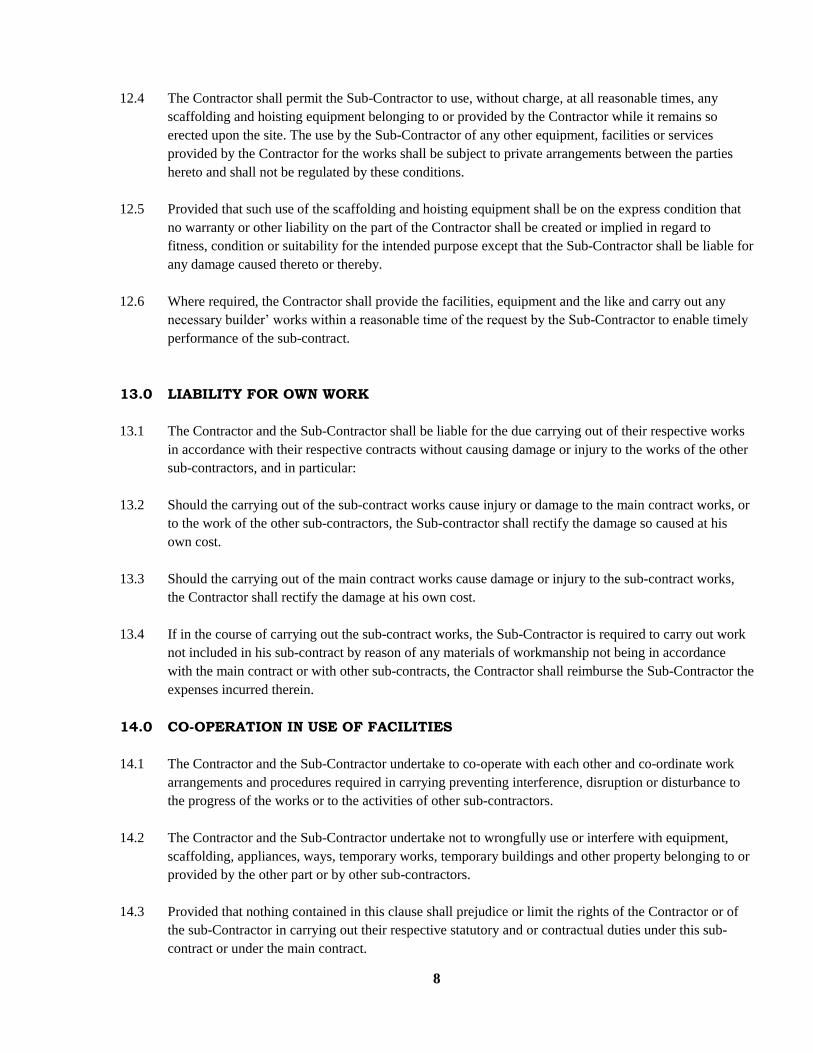
8
12.4 The Contractor shall permit the Sub-Contractor to use, without charge, at all reasonable times, any
scaffolding and hoisting equipment belonging to or provided by the Contractor while it remains so
erected upon the site. The use by the Sub-Contractor of any other equipment, facilities or services
provided by the Contractor for the works shall be subject to private arrangements between the parties
hereto and shall not be regulated by these conditions.
12.5 Provided that such use of the scaffolding and hoisting equipment shall be on the express condition that
no warranty or other liability on the part of the Contractor shall be created or implied in regard to
fitness, condition or suitability for the intended purpose except that the Sub-Contractor shall be liable for
any damage caused thereto or thereby.
12.6 Where required, the Contractor shall provide the facilities, equipment and the like and carry out any
necessary builder’ works within a reasonable time of the request by the Sub-Contractor to enable timely
performance of the sub-contract.
13.0 LIABILITY FOR OWN WORK
13.1 The Contractor and the Sub-Contractor shall be liable for the due carrying out of their respective works
in accordance with their respective contracts without causing damage or injury to the works of the other
sub-contractors, and in particular:
13.2 Should the carrying out of the sub-contract works cause injury or damage to the main contract works, or
to the work of the other sub-contractors, the Sub-contractor shall rectify the damage so caused at his
own cost.
13.3 Should the carrying out of the main contract works cause damage or injury to the sub-contract works,
the Contractor shall rectify the damage at his own cost.
13.4 If in the course of carrying out the sub-contract works, the Sub-Contractor is required to carry out work
not included in his sub-contract by reason of any materials of workmanship not being in accordance
with the main contract or with other sub-contracts, the Contractor shall reimburse the Sub-Contractor the
expenses incurred therein.
14.0 CO-OPERATION IN USE OF FACILITIES
14.1 The Contractor and the Sub-Contractor undertake to co-operate with each other and co-ordinate work
arrangements and procedures required in carrying preventing interference, disruption or disturbance to
the progress of the works or to the activities of other sub-contractors.
14.2 The Contractor and the Sub-Contractor undertake not to wrongfully use or interfere with equipment,
scaffolding, appliances, ways, temporary works, temporary buildings and other property belonging to or
provided by the other part or by other sub-contractors.
14.3 Provided that nothing contained in this clause shall prejudice or limit the rights of the Contractor or of
the sub-Contractor in carrying out their respective statutory and or contractual duties under this sub-
contract or under the main contract.

9
15.0 ASSIGNMENT AND SUBLETTING
15.1 Neither the Contractor nor the Sub-Contractor shall, without the written consent of the other and the
Employer, assign this sub-contract.
15.2 The Sub-Contractor shall not sub-let the whole of the works without the written consent of the
Contractor and the Architect.
15.3 Provided that any assignment and any sub-contracts as well as this sub-contract shall terminate
immediately upon (for whatever reason) of the main contract.
16.0 WORK PRIOR TO APPOINTMENT OF CONTRACTOR
16.1 Where the Sub-Contractor is appointed before the Contractor is appointed, any work done by the Sub-
Contractor prior to the said appointment shall be treated as a
Separate contract between the Employer and the Sub-Contractor and shall be valued by the Quantity
Surveyor and paid for directly by the Employer without the involvement of the Contractor.
16.2 Where the Sub-Contractor is appointed before the Contractor is appointed, the Sub-Contractor shall be
permitted, when the identity of the Contractor is known and within 30 days thereof, to raise objections
(on reasonable grounds) against entering into a sub-contract with the Contractor
16.3 Where work which is outside the sub-contract is ordered directly by Employer or the Architect, that
work shall be treated as a separate contract between the Sub-Contractor and the Employer and shall be
valued and paid for directly to the Sub-Contractor in accordance with sub-clause 16.1 herein without the
involvement of the Contractor. The cost of equipment, facilities and the like provided by the Contractor
to the Sub-contractor and any builder’s work carried out by the Contractor with regard to such work
shall be paid directly by the Sub-Contractor to the Contractor.
17.0 SUB-CONTRACTOR DESIGN
Where the sub-contract includes a design component by the Sub-Contractor, the design shall be to the approval
of the Architect and the Employer. Notwithstanding and approvals, the Sub-Contractor shall be liable directly to
the Employer for any consequences of failure of the design to comply with the requirements of the Employer or
to be fit or suitable for the purposes for which the sub-contract works or the relevant part thereof were intended.
18.0 SPECIFICATION OF GOODS, MATERIALS AND WORKMANSHIP
18.1 All materials, goods and workmanship shall, so far as procurable, be of the respective kinds and
standards described in the sub-contract bills, specifications and drawings.
18.2 The provisions of clause 23.0 of the main contract regulating the procurement, specification and quality
assurance of materials, processes and workmanship and the requirements of clause 24.0 therein dealing with the
provision of samples and the carrying out of specified tests shall apply to the sub-contract in the same manner as
they apply to the main contract.

10
19.0 COMPLIANCE WITH STATUTORY AND OTHER REGULATIONS
The Sub-Contract shall comply with all statutory and other regulations of competent authorities regulating the
carrying out of the works in accordance with the provisions of clause 17.0 of the main contract, as applicable.
20.0 ROYALTIES AND PATENT RIGHTS
20.1 All royalties or other sums payable in respect of the supply and use of any patented articles, processes or
inventions in carrying out the works as described by or referred to in the sub-contract bills,
specifications or drawings shall be deemed to have been included in the sub-contract price.
20.2 The provision of clause 25.0 of the main contract dealing with the same shall apply to the sub-contract
in the same manner as they apply to the main contract.
21.0 ANTIQUITIES AND OTHER OBJECTS OF VALUE
All fossils, antiquities and other objects of interest or value which may be found on the site or in excavating the
same during the progress of the sub-contract shall be dealt with in accordance with the provisions of clause 44.0
of the main contract.
22.0 SUSPENSION OF WORKS
22.1 An instruction by the Architect to postpone or suspend the works under clause 28.0 of the main contract
shall have the same effect on the sub-contract works as it has on the main contract works.
22.2 If the suspension arises due to default by the contractor and the sub-contract works are adversely
effected by the suspension, the sub-contractor shall be entitled to reimbursement by the contractor of all
expenses arising there from.
22.3 If the suspension arises due to default by the sub-contractor, the sub-contractor shall be liable to the
contractor for all expenses arising there from.
22.4 A notice by the contractor to suspend the works under clause 29.0 of the main contract shall have the
same effect on the sub-contract works as it has on the main contract works.
22.5 Should the sub-contract works be adversely affected by suspension under clause 29.0 of he main
contract, the sub-contractor shall be entitled to the remedies provided for at clauses 25.0 and 26.0 of this
sub-contract.
23.0 PAYMENTS
23.1 Procedures for originating and processing applications for payments and payment certificates as regards
the sub-contract works shall be the same as those prescribed for the Contractor in the main contract at
clause 34.0.All references therein to the contractor shall be deemed to include references to the Sub-
contractor.

11
23.2 Before submitting an application for payment to the Quantity Surveyor in accordance with clause 34.1
of the main contract, the Contractor shall give the Sub-Contractor a notice of not less than 7 days to
submit the details of the amounts which the Sub-Contractor considers himself entitled to for the relevant
period. Such details, when received, shall be annexed to the said Contractor’s application.
23.3 Where it is necessary to measure the sub-contract works for purpose of interim valuation or for the
preparation of the final account, the Quantity Surveyor shall give the Sub-Contractor a reasonable
opportunity to be present at the time of the measurements and to take notes and measurements as he may
require.
23.4 Neither the Quantity Surveyor nor the Architect shall be bound to issue a valuation or a payment
certificate in respect of the sub-contract works, as the case may be, whose value is less than the amount
stated in the appendix to these conditions as the minimum amount of a payment certificate before
the issue of the certificate of practical completion of the main contract or of the sub-contract, as
applicable.
23.5 Provided that where the minimum amount of a certificate inserted in the appendix to these conditions
has been achieved but the corresponding minimum inserted in the appendix to the main contract in
respect of the Contractor’s work has not been achieved, or the Contractor has not applied for payment
within the stated period, the Architect may with the consent of the Contractor, issue a payment
certificate directly to the Sub-Contractor for payment by the Employer.
23.6 Within 7 days of receipt by the Contractor of payment by the Employer, the Contractor shall notify and
pay to the Sub-Contractor the total value certified therein in respect of the sub-contract works less the
portion of the retention money attributable to the sub-contract works and less amounts previously paid to
the Sub-Contractor.
23.7 Where certificates are not paid by the Employer within the prescribed period, the Sub-Contractor shall
be entitled to be paid by the Contractor, upon receipt of payment from the Employer, the interest
certified for the delay in accordance with sub-clause 34.6 of the main contract in respect of the portion
of the sub-contract works included in the certificate.
23.8 Where the Contractor has received payment from the Employer but has not released the appropriate
amount to the Sub-Contractor within the stated period, the Contractor shall pay to the Sub-Contractor in
addition to the amount not paid, simple interest on the unpaid amount for the period it remains unpaid at
the commercial bank lending rate in force during the period of default.
23.9 If, upon application by the Sub-Contractor and Architect agree, or if the Contractor fails to make
payment to the Sub-Contractor in accordance with sub-clause 23.6 herein and continues such default for
14 days thereafter, the Architect may issue a payment certificate directly to the Sub-Contractor for
payment by the Employer, where applicable, and deduct the amount from subsequent payment to the
Contractor.
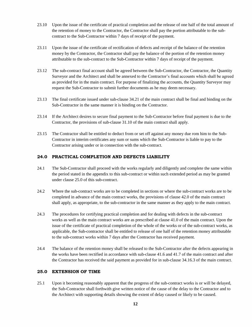
12
23.10 Upon the issue of the certificate of practical completion and the release of one half of the total amount of
the retention of money to the Contractor, the Contractor shall pay the portion attributable to the sub-
contract to the Sub-Contractor within 7 days of receipt of the payment.
23.11 Upon the issue of the certificate of rectification of defects and receipt of the balance of the retention
money by the Contractor, the Contractor shall pay the balance of the portion of the retention money
attributable to the sub-contract to the Sub-Contractor within 7 days of receipt of the payment.
23.12 The sub-contract final account shall be agreed between the Sub-Contractor, the Contractor, the Quantity
Surveyor and the Architect and shall be annexed to the Contractor’s final accounts which shall be agreed
as provided for in the main contract. For purpose of finalizing the accounts, the Quantity Surveyor may
request the Sub-Contractor to submit further documents as he may deem necessary.
23.13 The final certificate issued under sub-clause 34.21 of the main contract shall be final and binding on the
Sub-Contractor in the same manner it is binding on the Contractor.
23.14 If the Architect desires to secure final payment to the Sub-Contractor before final payment is due to the
Contractor, the provisions of sub-clause 31.10 of the main contract shall apply.
23.15 The Contractor shall be entitled to deduct from or set off against any money due rom him to the Sub-
Contractor in interim certificates any sum or sums which the Sub-Contractor is liable to pay to the
Contractor arising under or in connection with the sub-contract.
24.0 PRACTICAL COMPLETION AND DEFECTS LIABILITY
24.1 The Sub-Contractor shall proceed with the works regularly and diligently and complete the same within
the period stated in the appendix to this sub-contract or within such extended period as may be granted
under clause 25.0 of this sub-contract.
24.2 Where the sub-contract works are to be completed in sections or where the sub-contract works are to be
completed in advance of the main contract works, the provisions of clause 42.0 of the main contract
shall apply, as appropriate, to the sub-contractor in the same manner as they apply to the main contract.
24.3 The procedures for certifying practical completion and for dealing with defects in the sub-contract
works as well as the main contract works are as prescribed at clause 41.0 of the main contract. Upon the
issue of the certificate of practical completion of the whole of the works or of the sub-contract works, as
applicable, the Sub-contractor shall be entitled to release of one half of the retention money attributable
to the sub-contract works within 7 days after the Contractor has received payment.
24.4 The balance of the retention money shall be released to the Sub-Contractor after the defects appearing in
the works have been rectified in accordance with sub-clause 41.6 and 41.7 of the main contract and after
the Contractor has received the said payment as provided for in sub-clause 34.16.3 of the main contract.
25.0 EXTENSION OF TIME
25.1 Upon it becoming reasonably apparent that the progress of the sub-contract works is or will be delayed,
the Sub-Contractor shall forthwith give written notice of the cause of the delay to the Contractor and to
the Architect with supporting details showing the extent of delay caused or likely to be caused.

13
Thereafter, the Architect shall evaluate the information supplied by the Sub-Contractor and if in his
opinion the completion of the works is likely to be or has been delayed beyond the date for practical
completion stated in the appendix to these conditions or beyond any extended time previously fixed
under this clause, by any of the reasons entitling the Contractor to extension of time under sub-clause
36.1 of the main contract, then the Architect shall, so soon as he is able estimate the length of the delay
beyond the date or time aforesaid, recommend to the Contractor a fair and reasonable extension of time
to be granted for the completion of the sub-contract works.
25.2 Thereupon, the Contractor shall grant in writing to the Sub-Contractor the recommended time. Provided
that the Contractor shall not grant any extension of time to the Sub-Contractor without the written
recommendation of the Architect. And provided that the Sub-Contractor shall constantly use his best
endeavors to prevent delay and shall do all that may be reasonably required to proceed with the works.
25.3 The procedures for dealing with requests for extension of time and the observance of time limits
prescribed at clause 36.0 of the main contract shall apply to the sub-contract in the same manner as they
apply to the main contract.
26.0 LOSS AND EXPENSE CAUSED BY DISTURBANCE OF REGULAR PROGRESS
26.1 If upon written application being made by the Sub-Contractor to the Contractor and to the Architect, the
Architect is of the opinion that the Sub-Contractor has been involved in direct loss and or expense, for
which he would not be reimbursed by a payment made under any other provision in this sub-contract, by
reasons of the regular progress of the sub-contract works or any part thereof having been materially
affected by any of the reasons which would entitle the Contractor to reimbursement under clause 37.0 of
the main contract, the Quantity Surveyor shall assess the amount of such loss and or expense.
26.2 Any amount so assessed shall be added to the sub-contract price and if an interim certificate is issued
after the date of assessment, any such amount shall be added to the amount which would otherwise be
stated as due in such certificate as regards the Sub-Contractor’s entitlement.
26.3 The procedures for dealing with loss and or expense claims prescribed at clause 37.0 of the main
contract shall apply to the sub-contract in the same manner as they apply to the main contract, as
appropriate.
27.0 DAMAGES FOR DELAY IN COMPLETION
27.1 If the Sub-Contractor fails to complete the sub-contract works by the date for practical completion stated
in the appendix to these conditions or within any extended time fixed under clause 25.0 herein, and the
Architect certifies in writing that in his opinion the same ought reasonably so to have been completed,
then the Sub-Contractor shall pay or allow to the Contractor a sum calculated at the rate stated in the
said appendix as liquidated damages for the period during which the works shall so remain or have
remained incomplete.
27.2 The Contractor may deduct such sum from any money due or to become due to the Sub-Contractor
under the sub-contract or recover the same from the Sub-Contractor as a debt. Provided that the
Contractor shall not be entitled to recover any liquidated damages from the Sub-Contractor without first
obtaining the Architect’s certificate of delay prescribed herein.
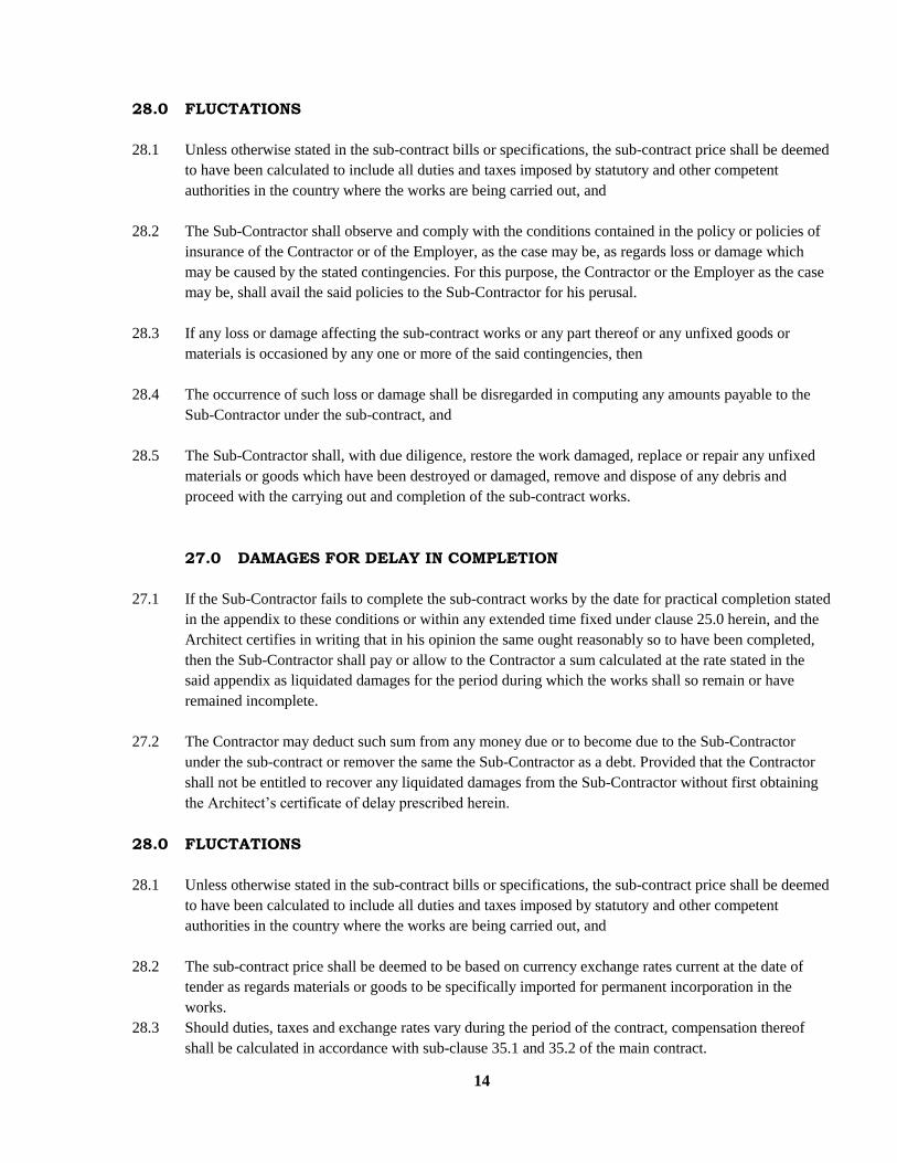
14
28.0 FLUCTATIONS
28.1 Unless otherwise stated in the sub-contract bills or specifications, the sub-contract price shall be deemed
to have been calculated to include all duties and taxes imposed by statutory and other competent
authorities in the country where the works are being carried out, and
28.2 The Sub-Contractor shall observe and comply with the conditions contained in the policy or policies of
insurance of the Contractor or of the Employer, as the case may be, as regards loss or damage which
may be caused by the stated contingencies. For this purpose, the Contractor or the Employer as the case
may be, shall avail the said policies to the Sub-Contractor for his perusal.
28.3 If any loss or damage affecting the sub-contract works or any part thereof or any unfixed goods or
materials is occasioned by any one or more of the said contingencies, then
28.4 The occurrence of such loss or damage shall be disregarded in computing any amounts payable to the
Sub-Contractor under the sub-contract, and
28.5 The Sub-Contractor shall, with due diligence, restore the work damaged, replace or repair any unfixed
materials or goods which have been destroyed or damaged, remove and dispose of any debris and
proceed with the carrying out and completion of the sub-contract works.
27.0 DAMAGES FOR DELAY IN COMPLETION
27.1 If the Sub-Contractor fails to complete the sub-contract works by the date for practical completion stated
in the appendix to these conditions or within any extended time fixed under clause 25.0 herein, and the
Architect certifies in writing that in his opinion the same ought reasonably so to have been completed,
then the Sub-Contractor shall pay or allow to the Contractor a sum calculated at the rate stated in the
said appendix as liquidated damages for the period during which the works shall so remain or have
remained incomplete.
27.2 The Contractor may deduct such sum from any money due or to become due to the Sub-Contractor
under the sub-contract or remover the same the Sub-Contractor as a debt. Provided that the Contractor
shall not be entitled to recover any liquidated damages from the Sub-Contractor without first obtaining
the Architect’s certificate of delay prescribed herein.
28.0 FLUCTATIONS
28.1 Unless otherwise stated in the sub-contract bills or specifications, the sub-contract price shall be deemed
to have been calculated to include all duties and taxes imposed by statutory and other competent
authorities in the country where the works are being carried out, and
28.2 The sub-contract price shall be deemed to be based on currency exchange rates current at the date of
tender as regards materials or goods to be specifically imported for permanent incorporation in the
works.
28.3 Should duties, taxes and exchange rates vary during the period of the contract, compensation thereof
shall be calculated in accordance with sub-clause 35.1 and 35.2 of the main contract.

15
28.4 Compensation for change in prices of goods and materials incorporated in the works and in the rates of
wages provided for at sub-clause 35.3,35.4 and 35.5 of the main contract shall not apply to the sub-
contract unless specifically provided for in the bill of quantities or specifications.
29.0 TERMINATION OF MAIN CONTRACT
29.1 If, for any reason, the contractor’s employment is terminated either under clause 38.0, 39.0 or 40.0 of
the main contract, this sub-contract shall thereupon also terminate.
29.2 Upon termination, the sub-contractor shall ceases all work and vacate the site. He shall not remove any
equipment or any materials brought onto the site for the carrying out of the works without the written
approval of the contractor and the Architect
29.3 Where the termination of the main contract occurs without the default of the sub-contractor, the sub-
contractor shall be paid by the contractor for work done in the like manner as the Contractor is paid at
clause 39.5 of the main contract.
29.4 Where the termination of main contract arises from the default by the sub-contractor, the adjustment of
the sub-contract accounts shall be performed in the like manner as is provided at sub-clause 38.8 of the
main contract regarding the main contract accounts.
30.0 TRMINATION OF SUB-CONTRACT.
30.1 Without prejudice to any other rights and remedies which the contractor may possess, if the sub-
contractor shall make default in any one or more of the respects which would entitle the employer to
terminate the main contract under clause 38.0 therein, the contractor shall give the sub- contractor
a notice, with a copy to the Architect and to the employer by registered post of recorded delivery
specifying the default. Should the sub-contractor continue the default for 14 days after receipt of such
notice or at any time thereafter repeat such default and should the Architect certify that the sub-
contractor is in default, the contractor may terminate the Sub-contract forthwith after the expiry of the
notice provided that the notice is not given unreasonably or vexatiously. The termination letter shall be
copied to the Architect and to the Employer.
30.2 Where the sub-contract is terminated due to the default of the sub-contractor as in sub-clause 30.1
herein, the adjustment of sub-contract accounts shall be performed in the like manner as is provided at
sub-clause 38.8 of the main contract regarding the main contract accounts.
30.3 Without prejudice to any other rights and remedies which the Sub-Contractor may possess, if the
Contractor shall make default in one or more of the respects which, if committed by the Employer,
would entitle the contractor to terminate the main contract under clause 39.0 therein, the Sub-Contractor
shall give the Contractor a notice, with a copy to the Architect and to the Employer, by registered post or
recorded delivery specifying the default. Should the contractor continue the default for 14 days after
receipt of such notice or at any time thereafter repeat such default, and should the Architect certify that
the contractor is in default, the Sub-Contractor may terminate the sub-contract forthwith after expiry of
the notice, provided that the notice is not given unreasonably or vexatiously. The termination letter shall
be copied to the Architect and to the Employer.

16
30.4 If the Sub-Contract is terminated due to the default of the Contractor as in sub- clause 30.3 herein, the
Contractor shall pay the sub-contractor for work done in the like manner as the Contractor would be
paid at sub-clause 39.5 of the main contract where the termination is done by the Contractor.
30.5 Where the sub-contract is terminated due to the default of the Contractor, all expenses arising from the
termination shall be done wholly by the Contractor and the termination shall not create any liability on
the Employer.
30.6 Where the sub-contract is terminated due to the default of the Sub-Contractor, the sub-contractor shall
be liable to the contractor for all expenses arising there from.
31.0 SETTLEMENT OF DISPUTES
31.1 In case any dispute or difference shall arise between the Contractor and Sub-Contractor, either during
the progress or after the completion or abandonment of the sub-contract works, such dispute shall be
notified in writing by either party to the other with a request to submit it to arbitration and to concur in
the appointment of an Arbitrator within 30 days of the notice.
31.2 The dispute shall be referred to the arbitration and final decision of a person to be agreed by the parties.
Failing agreement to concur in the appointment of an Arbitrator, the Arbitrator shall be appointment by
the Chairman or Vice Chairman of the Architectural Association of Kenya or the Chairman or Vice
Chairman of The Chartered Institute of Arbitrators, Kenya Branch, at the request of the applying party.
31.3 The arbitration may be on the construction of this sub-contract or on any matter or thing of whatsoever
nature arising there under or in connection therewith including the rights and liabilities of the parties
during the currency of the sub-contract and subsequent to the termination of the sub-contract.
31.4 Where the sub-contractor is aggrieved by the manner in which the Architect has exercised or failed to
exercise his powers stipulated in the main contract, or in the sub-contact or by any action or inaction of
the Employer, and in particular, if he is aggrieved by:
31.4.1 The failure or refusal of the Architect to recommend to the contractor an extension of sub-contract time,
or
31.4.2 The extend of the recommended time, or
31.4.3 The amount certified to the sub-contractor either in an interim in a Final certificate,or
31.4.4 The issue of an instruction which the sub-contractor contends is not authorised by the
main contract or the sub-contract, or
31.4.5. Any other matter left to the discretion of the Architect in the main contract or in the
sub-contract, then.
31.5 Subject to the Sub-Contractor giving the Contractor such indemnity and security as the Contractor may
reasonably require, the Contractor shall allow the Sub-Contractor to use the contractor’s name and, if
necessary, shall join the Sub-Contractor in arbitration proceeding against the employer to decide the
matters in dispute or in difference.

17
31.6 Provided that no arbitration proceedings shall be commenced on any dispute or difference where notice
of a dispute or difference where notice of a dispute or difference has not been given by the applying
party within 90 days of the occurrence or discovery of the matter or issue giving rise to the dispute or
difference.
31.7 Notwithstanding the issue of a notice as stated above, the arbitration of such a dispute or difference shall
not commence unless an attempt has in the first instance been made by the parties to settle such dispute
or difference amicably with or without the assistance of third parties.
31.8 In any event, no arbitration shall commence earlier than 90 days after the service of the notice of a
dispute or difference, except as provided for at sub-clause 31.9 herein.
31.9 Notwithstanding anything stated herein, the following matters may be referred to arbitration before the
practical completion of the works or abandonment of the works or termination of the sub-contract
without having to comply with sub clause 31.8 herein.
31.9.1 Whether or not the issue of an instruction by the Architect is authorized by the main contract or these
conditions, and
31.9.2 Whether or not a payment certificate has been improperly withheld or is not in accordance with the main
contract or these conditions or though issued, it has not been honoured.
31.10 All other matters in dispute shall only be referred to arbitration after the practical completion or alleged
practical completion of the works or abandonment of the works or termination or alleged termination of
the sub-contract, unless the Architect the contractor and the sub-contractor agree otherwise in writing.
31.11 The Arbitrator shall, without prejudice to the generality of his powers, have power to direct such
measurements, computations, tests, or valuations as may in his opinion be desirable in order to
determine the rights of the parties and assess and award any sums which ought to have been the subject
or included in any payment certificate.
31.12 The Arbitrator shall, without prejudice to the generality of his powers, have power to open up, review
and revise any certificate, opinion, decision, requirement or notice and to determine all matters in
dispute which shall be submitted to him in the same manner as if no such certificate, opinion decision,
requirement or notice had been given.
31.13 Provided that any decision of the Architect which is final and binding on the Contractor under the main
contract shall be final and binding between the Contractor and the Sub-Contractor.
31.14 The award of such Arbitrator shall be final and binding upon the parties.

18
SUB CONTRACTOR’S PERFORMANCE BOND
BY THIS AGREEMENT we ................................................................................(SURETY)
of ..........................................................................................................................................
are bound to .............................................................................................(CONTRACTOR)
in the sum of Kenya shillings ..............................................................................................
.......................................................................................(Kshs.............................................)
to be paid by us to the said ......................................................................(CONTRACTOR)
WHEREAS by an agreement in writing dated .....................................................................
.........................................................................................................(SUB-CONTRACTOR)
entered into a sub-contract with ...............................................................(CONTRACTOR)
to carry out and complete the works therein stated in the manner and by the time therein
specified all in accordance with he provisions of the said sub-contract, namely: (description of works)
..............................................................................................................................................
NOW the condition of the above written bond is such that if the said Sub-Contractor, his
Executors, administrator, successors or assigns shall duly perform his obligations under the Sub-Contract, if on
default by the Sub-Contractor the surety shall satisfy and discharge the damages sustained by the Contractor
thereby up to the amount of the above written bond, then this obligation shall be void, otherwise it shall remain
in full force and effect. Upon default, and without prejudice to his other rights under the Sub-Contract, the
contractor shall be entitled to demand forfeiture of the bond and we undertake to honour the demand in the
amount stated above.
PROVIDED always and it is hereby agreed and declared that no alteration in the terms of the said Sub-Contract
or in the extend or nature of the works to be carried out and no extension of time by the Contractor under the
sub-contract shall in any way release the surety from any liability under the above written bond.
IN WITNESS whereof we have set out hand this .............. day of ......................................
.......................................... ....................................................................
Surety Witness
Authrorised of Power of Attoney No ...............
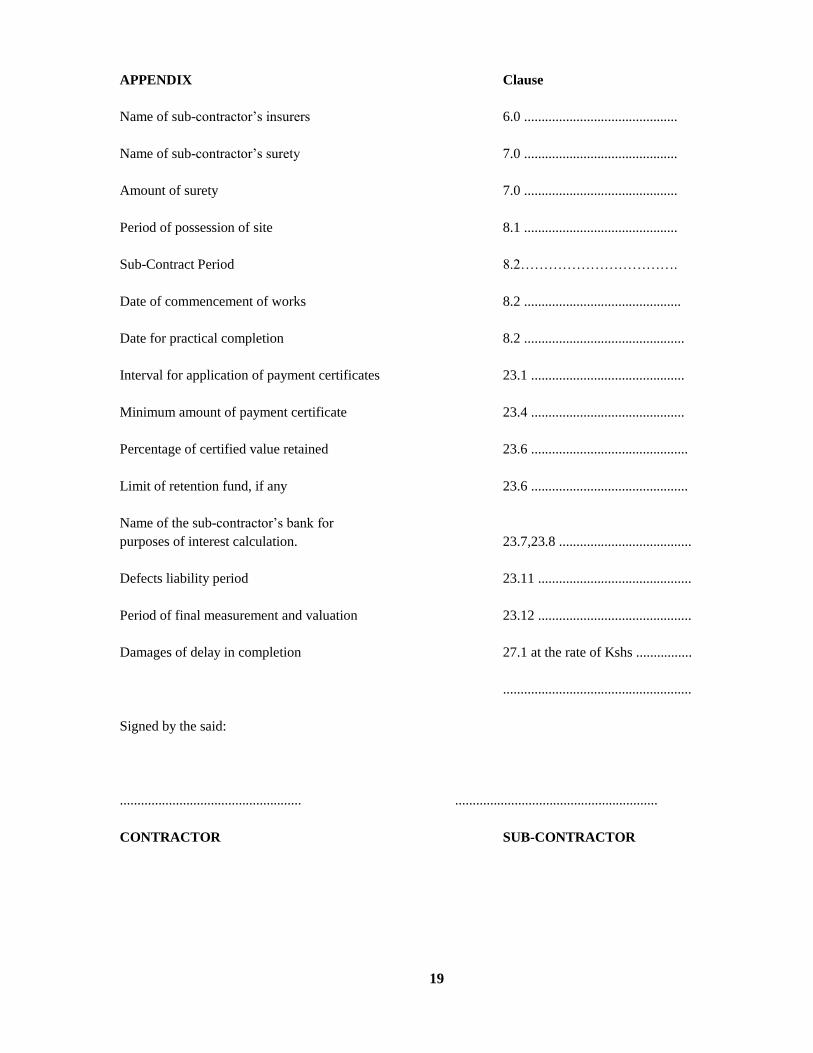
19
APPENDIX Clause
Name of sub-contractor’s insurers 6.0 ............................................
Name of sub-contractor’s surety 7.0 ............................................
Amount of surety 7.0 ............................................
Period of possession of site 8.1 ............................................
Sub-Contract Period 8.2…………………………….
Date of commencement of works 8.2 .............................................
Date for practical completion 8.2 ..............................................
Interval for application of payment certificates 23.1 ............................................
Minimum amount of payment certificate 23.4 ............................................
Percentage of certified value retained 23.6 .............................................
Limit of retention fund, if any 23.6 .............................................
Name of the sub-contractor’s bank for
purposes of interest calculation. 23.7,23.8 ......................................
Defects liability period 23.11 ............................................
Period of final measurement and valuation 23.12 ............................................
Damages of delay in completion 27.1 at the rate of Kshs ................
......................................................
Signed by the said:
.................................................... ..........................................................
CONTRACTOR SUB-CONTRACTOR

20
APPENDIX TO KABCEC
(1) Amend clause 17
Replace ‘ Architect’ with “ Engineer”
(2) Amend clause 7
The surety must be from an Established/Reputable Bank, and is 5%
(3) Amend clause 28
Shall apply as per main contract

21
SECTION C
SUB-CONTRACT PRELIMINARIES
AND
GENERAL CONDITIONS

i
SECTION C
GENERAL MECHANICAL SPECIFICATION
CLAUSE DESCRIPTION PAGE
1.01 Examination of Tender Documents .............................................................................. 3
1.02 Discrepancies ................................................................................................................ 3
1.03 Conditions of Contract Agreement ................................................................................. 3
1.04 Payment ........................................................................................................................ 4
1.05 Definition of Terms ...................................................................................................... 4
1.06 Site Location ................................................................................................................. 5
1.07 Duration of Sub-Contract ............................................................................................. 5
1.08 Scope of Contract Works .............................................................................................. 5
1.09 Extent of the Sub-contractor’s Duties .......................................................................... 5
1.10 Execution of the Works ................................................................................................ 6
1.14 Prime Cost and Provisional Sums ................................................................................ 7
1.15 Bond.............................................................................................................................. 7
1.16 Government Legislation and Regulations .................................................................... 7
1.17 Import Duty and Value Added Tax .............................................................................. 8
1.18 Insurance Company Fees .............................................................................................. 8
1.19 Provision of Services by the Main Contractor.............................................................. 8
1.20 Suppliers ....................................................................................................................... 8
1.21 Samples and Materials Generally ................................................................................. 9
1.22 Administrative Procedure and Contractual Responsibility .......................................... 9
1.23 Bills of Quantities ......................................................................................................... 9
1.24 Contractor’s Office in Kenya ....................................................................................... 9
1.25 Builder’s Work ........................................................................................................... 10
1.26 Structural Provision for the Works ............................................................................. 10
1.27 Position of Services, Plant, Equipment, Fittings and Apparatus ................................ 10
1.28 Checking of Work ...................................................................................................... 11
1.29 Setting to Work and Regulating System ..................................................................... 11
1.30 Identification of Plant Components ............................................................................ 11
1.31 Contract Drawings ...................................................................................................... 11
1.32 Working Drawings ..................................................................................................... 12
1.33 Record Drawings (As Installed) and Instructions ....................................................... 13
1.34 Maintenance Manual .................................................................................................. 14
1.35 Hand-over ................................................................................................................... 15

ii
1.36 Painting ....................................................................................................................... 16
1.37 Spares.......................................................................................................................... 16
1.38 Testing and Inspection – Manufactured Plant ............................................................ 16
1.39 Testing and Inspection -Installation ........................................................................... 16
1.40 Labour Camps............................................................................................................. 16
1.41 Storage of Materials .................................................................................................... 17
1.42 Initial Maintenance ..................................................................................................... 17
1.43 Maintenance and Servicing After Completion of the Initial Maintenance ................. 17
1.44 Trade Names ............................................................................................................... 18
1.45 Water and Electricity for the Works ........................................................................... 18
1.46 Protection .................................................................................................................... 18
1.47 Defects After Completion ........................................................................................... 18
1.48 Damages for Delay ..................................................................................................... 18
1.49 Clear Away on Completion ........................................................................................ 18
1.50 Final Account ............................................................................................................. 18
1.51 Fair Wages .................................................................................................................. 19
1.52 Supervision ................................................................................................................. 19
1.53 Test Certificates .......................................................................................................... 19
1.54 Labour ......................................................................................................................... 19
1.55 Discount to the Main Contractor ................................................................................ 19
1.56 Guarantee .................................................................................................................... 20
1.57 Direct Contracts ......................................................................................................... 20
1.58 Attendance Upon the Tradesmen etc .......................................................................... 20
1.59 Trade Unions .............................................................................................................. 20
1.63 Temporary Works ....................................................................................................... 21
1.65 Mobilization and Demobilization ............................................................................... 21
1.66 Extended Preliminaries ............................................................................................... 22
1.67 Supervision by Engineer and Site Meetings ............................................................... 22
1.68 Amendment to Scope of Contract Works ................................................................... 22
1.69 Contractor Obligation and Employers Obligation ...................................................... 23
1.70 APPENDIX TO SUB-CONTRACT PRELIMINARIES AND GENERAL
CONDITIONS .......................................................................................................................... 23

3
SECTION C
SUB-CONTRACT PRELIMINARIES AND GENERAL CONDITIONS
1.01 Examination of Tender Documents
The tenderer is required to check the number of pages of this document and should he find any missing or
indistinct, he must inform the Engineer at once and have the same rectified.
All tenderers shall be deemed to have carefully examined the following:
Work detailed in the Specification and in the Contract Drawings.
The Republic of Kenya Document “General Conditions of Contract for Electrical and Mechanical Works”.
Other documents to which reference is made.
He shall also be deemed to have included for any expenditure which may be incurred in conforming with the
above items (a), (b), (c) and observe this expense as being attached to the contract placed for the whole or any
part of the work.
The tenderer shall ensure that all ambiguities, doubts or obscure points of detail, are clarified with the Engineer
before submission of his tender, as no claims for alleged deficiencies in the information given shall be
considered after this date.
1.02 Discrepancies
The Contractor shall include all work either shown on the Contract Drawings or detailed in the specification.
No claim or extra cost shall be considered for works which has been shown on the drawings or in the
specification alone.
Should the drawing and the specification appear to conflict, the Sub-contractor shall query the points at the
time of tendering and satisfy himself that he has included for the work intended, as no claim for extra payment
on this account shall be considered after the contract is awarded.
1.03 Conditions of Contract Agreement
The Contractor shall be required to enter into a Sub-contract with the Main Contractor.
The Conditions of the Contract between the Main Contractor and any Sub-contractor as hereinafter defined
shall be the latest edition of the Agreement and Schedule of Conditions of Kenya Association of Building and
Civil Engineering Contractors as particularly modified and amended hereinafter.
For the purpose of this contract the Agreement and Schedule of Conditions and any such modifications and
amendments shall read and construed together. In any event of discrepancy, the modifications and
amendments shall prevail.

4
1.04 Payment
Payment will be made through certificates to the Main Contractor, All payments will be less retention as
specified in the Main Contract. No payment will become due until materials are delivered to site.
1.05 Definition of Terms
Throughout these contract documents units of measurements, terms and expressions are abbreviated and
wherever used hereinafter and in all other documents they shall be interpreted as follows:
i) Employer: The term “Employer” shall mean Kiambu County Government.
ii) Architect: The term “Architect” shall mean The Kiambu County Architect,
iii) Quantity Surveyor: The term “Quantity Surveyor” shall mean The Kiambu County Quantity
Surveyor
iv) Civil/Structural Engineers: The term “Civil/Structural Engineers” shall mean The Kiambu
County Structural Engineer
v) Engineer: The term “Engineer” shall mean Kiambu County Mechanical Engineer
vi) Main Contractor: The term “Main Contractor” shall mean the firm or company appointed to carry
out the Building Works and shall include his or their heir, executors, assigns, administrators, successors, and
duly appointed representatives.
Sub-contractor: The term “Sub-contractor” shall mean the persons
or person, firm or Company whose tender for this work has been accepted, and who has entered into a contract
agreement with the Contractor for the execution of the Sub-contract Works, and shall include his or their heirs,
executors, administrators, assigns, successors and duly appointed representatives.
viii) Sub-contract Works: The term “Sub-contract Works” shall mean all or any portion of the work,
materials and articles, whether the same are being manufactured or prepared, which are to be used in the
execution of this Sub-contract and whether the same may be on site or not.
Contract Drawings: The term “Contract Drawings” shall mean those drawings required or referred to
herein and forming part of the Bills of Quantities.
Working Drawings: The term “Working Drawings” shall mean those drawings required to be prepared by
the Sub-contractor as hereinafter described.
xi) Record Drawings: The term “Record Drawings” shall mean those drawings required to be prepared
by the Sub-contractor showing “as installed” and other records for the Sub-contract Works.
5
xii) Abbreviations:
CM shall mean Cubic Metre
SM shall mean Square Metre
LM shall mean Linear Metre
LS shall mean Lump Sum
mm shall mean Millimeters
No. Shall mean Number
Kg. shall mean Kilogramme
KEBS or KS shall mean Kenya Bureau of Standards
BS shall mean. Current standard British Standard Specification published
by the British Standard Institution, 2 Park Street, London W1, England
“Ditto” shall mean the whole of the preceding description in which it occurs. Where it occurs in description
of succeeding item it shall mean the same as in the first description of the series in which it occurs except as
qualified in the description concerned. Where it occurs in brackets it shall mean the whole of the preceding
description which is contained within the appropriate brackets.
1.06 Site Location
The site of the Contract Works is situated at Gatundu Town, Kiambu County.
The tenderer is recommended to visit the site and shall be deemed to have satisfied himself with regard to
access, possible conditions, the risk of injury or damage to property on/or adjacent to the site, and the
conditions under which the sub-contract Works shall have to be carried out and no claims for extras will be
considered on account of lack of knowledge in this respect.
1.07 Duration of Sub-Contract
The Contractor shall be required to phase his work in accordance with the Main contractor’s programme (or its
revision).
1.08 Scope of Contract Works
The contractor shall supply, deliver, unload, hoist, fix, test, commission and hand-over in satisfactory working
order the complete installations specified hereinafter and/or as shown on the Contract Drawings attached
hereto, including the provision of labour, transport and plant for unloading material and storage, and handling
into position and fixing, also the supply of ladders, scaffolding the other mechanical devices to plant,
installation, painting, testing, setting to work, the removal from site from time to time of all superfluous
material and rubbish caused by the works.
The contractor shall supply all accessories, whether of items or equipment supplied by the Sub-Contractor but
to be fixed and commissioned under this contract.
1.09 Extent of the Sub-contractor’s Duties
At the commencement of the works, the contractor shall investigate and report to the Engineer if all materials
and equipment to be used in the work and not specified as supplied by the others are available locally. If these
materials and equipment are not available locally, the contractor shall at this stage place orders for the

6
materials in question and copy the orders to the Engineer. Failure to do so shall in no way relieve the
contractor from supplying the specified materials and equipment in time.
Materials supplied by others for installation and/or connection by the Contractor shall be carefully examined in
the presence of the supplier before installation and connection. Any defects noted shall immediately be
reported to the Engineer.
The contractor shall be responsible for verifying all dimensions relative to his work by actual measurements
taken on site.
The Contractor shall mark accurately on one set of drawings and Indicate all alterations and/or modifications
carried out to the designed System during the construction period. This information must be made available on
site for inspection by the Engineer.
1.10 Execution of the Works
The works shall be carried out strictly in accordance with:
a) All relevant Kenya Bureau of Standards Specifications.
b) All relevant British Standard Specifications and Codes of Practice (hereinafter referred to B.S. and
C.P. respectively).
c) General specifications of materials and works Section D of this document
d) The Contract Drawings.
e) The Bye-laws of the Local Authority.
f) The Architect’s and/or Engineer’s Instructions.
The Contract Drawings and Specifications are to be read and construed together.
1.11 Validity of Tender
The tender shall remain valid for acceptance within 120 days from the final date of submission of the tender,
and this has to be confirmed by signing the Tender Bond. The tenderer shall be exempted from this Bond if
the tender was previously withdrawn in writing to the Employer before the official opening.
1.12 Firm – Price Contract
Unless specifically stated in the documents or the invitation to tender, this is a firm-price Contract and the
contractor must allow in his tender for the increase in the cost of labour and/or materials during the duration of
the contract. No claims will be allowed for increased costs arising from the fluctuations in duties and/or day to
day currency fluctuations. The Sub-contractor will be deemed to have allowed in his tender for any increase in
the cost of materials, which may arise as a result of currency fluctuation during the contract period.

7
1.13 Variation
No alteration to the Contract Works shall be carried out until receipt by the Contractor of written instructions
from the Project Manager.
Any variation from the contract price in respect of any extra work, alteration or omission requested or
sanctioned by the Engineer shall be agreed and confirmed in writing at the same time such variations are
decided and shall not affect the validity of the Contract. Schedule of Unit Rates shall be used to assess the
value of such variations. No allowance shall be made for loss of profit on omitted works.
Where the Architect requires additional work to be performed, the Sub-contractor, if he considers it necessary,
will give notice within seven (7) days to the Main Contractor of the length of time he (the Sub-contractor)
requires over and above that allotted for completion of the Contract.
If the Sub-contractor fails to give such notice he will be deemed responsible for the claims arising from the
delay occasioned by reason of such extension of time.
1.14 Prime Cost and Provisional Sums
A specialist Sub-contractor may be nominated by the Project Manager to supply and/or install any equipment
covered by the Prime Cost or Provisional Sums contained within the Contract documents.
The work covered by Prime Cost and Provisional Sums may or may not be carried out at the discretion of the
Project Manager.
The whole or any part of these sums utilised by the Contractor shall be deducted from the value of the Contract
price when calculating the final account.
1.15 Bond
The tenderer must submit with his tender the name of one Surety who must be an established Bank only who
will be willing to be bound to the Government for an amount equal to 7½ % of the Contract amount as Clause
28 of the Conditions of Contract.
1.16 Government Legislation and Regulations
The Contractor’s attention is called to the provision of the Factory Act 1972 and subsequent amendments and
revisions, and allowance must be made in his tender for compliance therewith, in so far as they are applicable.
The Contractor must also make himself acquainted with current legislation and any Government regulations
regarding the movement, housing, security and control of labour, labour camps, passes for transport, etc.
The Contractor shall allow for providing holidays and transport for work people, and for complying with
Legislation, Regulations and Union Agreements.

8
1.17 Import Duty and Value Added Tax
The Sub-contractor will be required to pay full Import Duty and Value Added Tax on all items of equipment,
fittings and plant, whether imported or locally manufactured. The tenderer shall make full allowance in his
tender for all such taxes.
1.18 Insurance Company Fees
Attention is drawn to the tenderers to allow for all necessary fees, where known, that may be payable in respect
of any fees imposed by Insurance Companies or statutory authorities for testing or inspection.
No allowance shall be made to the contractor with respect to fees should these have been omitted by the
tenderer due to his negligence in this respect.
1.19 Provision of Services by the Main Contractor
In accordance with Clause 1.08 of this Specification the Contractor shall make the following facilities
available to the Sub-contractor:
a) Attendance on the Sub-Contractor and the carrying out of all work affecting the structure of the
building which may be necessary, including all chasing, cutting away and making good brickwork,
etc., except that all plugging for fixing, fittings, machinery, fan ducting, etc., and all drilling and
tapping of steel work shall be the responsibility of the Sub-contractor. Any purpose made fixing
brackets shall not constitute Builder’s Work and shall be provided and installed by the Sub-contractor
unless stated hereinafter otherwise.
b) The provision of temporary water, lighting and power: the Contractor pay for all these services
utilized.
c) Fixing of anchorage and pipe supports in the shuttering, shall be supplied by the Contractor who shall
also supply the Project Manager with fully dimensioned drawings detailing the exact locations.
d) i)Provision of scaffolding, cranes, etc. It shall be the Contractor’s responsibility to liaise with the
Project Manager to ensure that there is maximum co-operation with other nominated Sub-contractors
in the use of scaffolding, cranes, etc.
ii) Any specialist scaffolding, cranes, etc. by the Contractor for his own exclusive use shall be paid for
by the Sub-contractor.
1.20 Suppliers
The Contractor shall submit names of any supplier for the materials to be incorporated, to the Engineer for
approval. The information regarding the names of the suppliers may be submitted at different times, as may be
convenient, but no sources of supply will be changed without prior approval.
Each supplier must be willing to admit the Engineer or his representative to his premises during working hours
for the purpose of examining or obtaining samples of the materials in question

9
1.21 Samples and Materials Generally
The Contractor shall, when required, provide for approval at no extra cost, samples of all materials to be
incorporated in the works. Such samples, when approved, shall be retained by the Engineer and shall form the
standard for all such materials incorporated.
1.22 Administrative Procedure and Contractual Responsibility
Wherever within the Specification it is mentioned or implied that the Contractor shall deal direct with the
Employer or Engineer, it shall mean “through the Project Manager who is responsible to the Employer for the
whole of the works including the Sub-contract Works.
1.23 Bills of Quantities
The Bills of Quantities have been prepared in accordance with the standard method of measurement of
Building Works for East Africa, first Edition, Metric, 1970. All the Quantities are based on the Contract
Drawings and are provisional and they shall not be held to gauge or to limit the amount or description of the
work to be executed by the Contractor but the value thereof shall be deducted from the Contract Sum and the
value of the work ordered by the Engineer and executed thereunder shall be measured and valued by the
Engineer in accordance with the conditions of the Contract.
All work liable to adjustment under this Contract shall be left uncovered for a reasonable time to allow
measurements needed for such adjustment to be taken by the Quantity Surveyor or Engineer. Immediately the
work is ready for measuring the Contractor shall give notice to the Quantity Surveyor or Engineer to carry out
measurements before covering up. If the Contractor shall make default in these respects he shall, if the
Engineer so directs, uncover the work to enable the necessary measurements to be taken and afterwards
reinstate at his own expense.
1.24 Contractor’s Office in Kenya
The Contractor shall maintain (after first establishing if necessary) in Kenya an office staffed with competent
Engineer Manager and such supporting technical and clerical staff as necessary to control and coordinate the
execution and completion of the Contract Works.
The Engineer Manager and his staff shall be empowered by the Contractor to represent him at meetings and in
discussions with the Project Manager, the Engineer and other parties who may be concerned and any liaison
with the Contractor’s Head Office on matters relating to the design, execution and completion of the Contract
Works shall be effected through his office in Kenya.
It shall be the Contractor’s responsibility to procure work permits, entry permits, licences, registration, etc., in
respect of all expatriate staff.
The Contractor shall prepare a substantial proportion of his Working Drawings at his office in Kenya. No
reasons for delays in the preparation or submission for approval or otherwise of such drawings or proposals
will be accepted on the grounds that the Sub-contractor’s Head Office is remote from his office in Nairobi or
the site of the Contract Works or otherwise.

10
1.25 Builder’s Work
All chasing, cutting away and making good will be done by the Contractor. The Contractor shall mark out in
advance and shall be responsible for accuracy of the size and position of all holes and chases required.
The Contractor shall drill and plug holes in floors, walls, ceiling and roof for securing services and equipment
requiring screw or bolt fixings.
Any purpose made fixing brackets shall be provided and installed by the Contractor.
1.26 Structural Provision for the Works
Preliminary major structural provision has been made for the Contract Works based on outline information
ascertained during the preparation of the Specification.
The preliminary major structural provision made will be deemed as adequate unless the Contractor stated
otherwise when submitting his tender.
Any major structural provision or alteration to major structural provisions required by the Contractor shall be
shown on Working Drawings to be submitted to the Engineer within 30 days of being appointed.
No requests for alterations to preliminary major structural provisions will be approved except where they are
considered unavoidable by the Engineer. In no case will they be approved if building work is so far advanced
as to cause additional costs or delays in the works.
1.27 Position of Services, Plant, Equipment, Fittings and Apparatus
The Contract Drawings give a general indication of the intended layout. The position of the equipment and
apparatus, and also the exact routes of the ducts, main and distribution pipework shall be confirmed before
installation is commenced. The exact siting of appliances, pipework, etc., may vary from that indicated.
The routes of services and positions of apparatus shall be determined by the approved dimensions detailed in
the Working Drawings or on site by the Engineer in consultation with the Contractor.
Services through the ducts shall be arranged to allow maximum access along the ducts and the services shall be
readily accessible for maintenance. Any work, which has to be re-done due to negligence in this respect shall
be the Sub-contractor’s responsibility.
The Sub-contractor shall be deemed to have allowed in his Contract Sum for locating terminal points of
services (e.g. lighting, switches, socket outlets, lighting points, control switches, thermostats and other
initiating devices, taps, stop cocks) in positions plus or minus 1.2m horizontally and vertically from the
locations shown on Contract Drawings. Within these limits no variations in the Contract Sum will be made
unless the work has already been executed in accordance with previously approved Working Drawings and
with the approval of the Engineer.

11
1.28 Checking of Work
The Contractor shall satisfy himself to the correctness of the connections he makes to all items of equipment
supplied under the Contract agreement and equipment supplied under other contracts before it is put into
operation. Details of operation, working pressures, temperatures, voltages, phases, power rating, etc., shall be
confirmed to others and confirmation received before the system is first operated.
1.29 Setting to Work and Regulating System
The Contractor shall carry out such tests of the Contract Works as required by British Standard Specifications,
or equal and approved codes as specified hereinafter and as customary.
No testing or commissioning shall be undertaken except in the presence of and to the satisfaction of the
Engineer unless otherwise stated by him (Contractor’s own preliminary and proving tests excepted).
It will be deemed that the Contractor has included in the Contract Sum for the costs of all fuel, power, water
and the like, for testing and commissioning as required as part of the Contract Works. He shall submit for
approval to the Engineer a suitable programme for testing and commissioning. The Engineer and Employer
shall be given ample warning in writing, as to the date on which testing and commissioning will take place.
The Contractor shall commission the Contract Works and provide attendance during the commissioning of all
services, plant and apparatus connected under the Contract Agreement or other Sub-contract Agreements,
related to the project.
Each system shall be properly balanced, graded and regulated to ensure that correct distribution is achieved
and where existing installations are affected, the Contractor shall also regulate these systems to ensure that
their performance is maintained.
The proving of any system of plant or equipment as to compliance with the Specification shall not be approved
by the Engineer, except at his discretion, until tests have been carried out under operating conditions pertaining
to the most onerous conditions specified except where the time taken to obtain such conditions is unreasonable
or exceeds 12 months after practical completion of the Contract Works.
1.30 Identification of Plant Components
The Contractor shall supply and fix identification labels to all plant, starters, switches and items of control
equipment including valves, with white traffolyte or equal labels engraved in red lettering denoting its name,
function and section controlled. The labels shall be mounted on equipment and in the most convenient
positions. Care shall be taken to ensure the labels can be read without difficulty. This requirement shall apply
also to major components of items of control equipment.
Details of the lettering of the labels and the method of mounting or supporting shall be forwarded to the
Engineer for approval prior to manufacture.
1.31 Contract Drawings
The Contract Drawings when read in conjunction with the text of the Specification, have been completed in
such detail as was considered necessary to enable competitive tenders to be obtained for the execution and
completion of the Contract works.

12
The Contract Drawings are not intended to be Working Drawings and shall not be used unless exceptionally
they are released for this purpose.
1.32 Working Drawings
The Contractor shall prepare such Working Drawings as may be necessary. The Working Drawings shall be
complete in such detail not only that the Contract Works can be executed on site but also that the Engineer can
approve the Contractor’s proposals, detailed designs and intentions in the execution of the Contract Works.
If the Contractor requires any further instructions, details, Contract Drawings or information drawings to
enable him to prepare his Working Drawings or proposals, the Contractor shall accept at his own cost, the risk
that any work, commenced or which he intends to commence at site may be rejected.
The Engineer, in giving his approval to the Working Drawings, will presume that any necessary action has
been, or shall be taken by the Contractor to ensure that the installations shown on the Working Drawings have
been cleared with the Project Manager and any other Sub-contractors whose installations and works might be
affected.
If the Contractor submits his Working Drawings to the Engineer without first liaising and obtaining clearance
for his installations from the Project Manager and other Sub-contractors whose installations and works might
be affected, then he shall be liable to pay for any alterations or modification to his own, or other Sub-
contractor’s installations and works, which are incurred, notwithstanding any technical or other approval
received from the Engineer.
Working Drawings to be prepared by the Contractor shall include but not be restricted to the following:
Any drawings required by the Engineer to enable structural provisions
to be made including Builder’s Working Drawings or Schedules and those for the detailing of holes, fixings,
foundations, cables and paperwork ducting below or above ground or in or outside or below buildings.
General Arrangement Drawings of all plant, control boards, fittings and apparatus or any part thereof and of
installation layout arrangement of such plant and apparatus.
Schematic Layout Drawings of services and of control equipment.
Layout Drawings of all embedded and non-embedded paperwork, ducts and electrical conduits.
Complete circuit drawings of the equipment, together with associated circuit description.
Such other drawings as are called for in the text of the Specification or Schedules or as the Engineer may
reasonably require.
Three copies of all Working Drawings shall be submitted to the Engineer for approval. One copy of the
Working Drawings submitted to the Engineer for approval shall be returned to the Contractor indicating
approval or amendment therein.

13
Six copies of the approved Working Drawings shall be given to the Project Manager by the Sub-contractor for
information and distribution to other Sub-contractors carrying out work associated with or in close proximity
to or which might be affected by the Sub-contract Works.
Approved Working Drawings shall not be departed from except as may be approved or directed by the
Engineer.
Approval by the Engineer of Working Drawings shall neither relieve the Contractor of any of his obligations
under the Sub-contract nor relieve him from correcting any errors found subsequently in the Approved
Working Drawings or other Working Drawings and in the Sub-contract Works on site or elsewhere associated
therewith.
The Contractor shall ensure that the Working Drawings are submitted to the Engineer for approval at a time
not unreasonably close to the date when such approval is required. Late submission of his Working Drawings
will not relieve the Contractor of his obligation to complete the Contract Works within the agreed Contract
Period and in a manner that would receive the approval of the Engineer.
1.33 Record Drawings (As Installed) and Instructions
During the execution of the Contract Works the Contractor shall, in a manner approved by the Engineer record
on Working or other Drawings at site all information necessary for preparing Record Drawings of the installed
Contract Works. Marked-up Working or other Drawings and other documents shall be made available to the
Engineer as he may require for inspection and checking.
Record Drawings, may, subject to the approval of the Engineer, include approved Working Drawings adjusted
as necessary and certified by the Contractor as a correct record of the installation of the Contract Works.
They shall include but not restricted to the following drawings or information:
Working Drawings amended as necessary but titled “Record Drawings” and certified as a true record of the
“As Installed” Sub-contract Works. Subject to the approval of the Engineer such Working Drawings as may
be inappropriate may be omitted.
Fully dimensioned drawings of all plant and apparatus.
General arrangement drawings of equipment, other areas containing plant forming part of the Contract Works
and the like, indicating the accurate size and location of the plant and apparatus suitability cross-referenced to
the drawings mentioned in (b) above and hereinafter.
Routes, types, sizes and arrangement of all pipework and ductwork including dates of installation of
underground pipework.
Relay adjustment charts and manuals.
Routes, types, sizes and arrangement of all electric cables, conduits, ducts and wiring including the dates of
installation of buried works.
System schematic and trunking diagrams showing all salient information relating to control and
instrumentation.

14
Grading Charts.
Valve schedules and locations suitability cross-referenced.
Wiring and piping diagrams of plant and apparatus.
Schematic diagrams of individual plant, apparatus and switch and control boards. These diagrams to include
those peculiar to individual plant or apparatus and also those applicable to system operation as a whole.
Operating Instruction
Schematic and wiring diagrams shall not be manufacturer’s multipurpose general issue drawings. They shall be
prepared specially for the Contract Works and shall contain no spurious or irrelevant information.
Marked-up drawings of the installation of the Contract Works shall be kept to date and completed by the date
of practical or section completion. Two copies of the Record Drawings of Contract Works and two sets of the
relay adjustment and grading charts and schematic diagrams on stiff backing shall be provided not later than
one month later.
The Contractor shall supply for fixing in sub-stations, switch-rooms, boiler houses, plant rooms, pump houses,
the office of the Maintenance Engineer and other places, suitable valve and instructions charts, schematic
diagrams of instrumentation and of the electrical reticulation as may be requested by the Engineer providing
that the charts, diagrams, etc., relate to installations forming part of the Contract Works. All such charts and
diagrams shall be of suitable plastic material on a stiff backing and must be approved by the Engineer before
final printing.
Notwithstanding the Contractor’s obligations referred to above, if the Contractor fails to produce to the
Engineer’s approval, either:-
The Marked-up Drawings during the execution of the Contract Works or
The Record Drawings, etc., within one month of the Section or Practical Completion
The Engineer shall have these drawings produced by others. The cost of obtaining the necessary information
and preparing such drawings, etc., will be recovered from the Contractor.
1.34 Maintenance Manual
Upon Practical Completion of the Contract Works, the Contractor shall furnish the Engineer four copies of a
Maintenance Manual relating to the installation forming part of all of the Contract Works.
The manual shall be loose-leaf type, International A4 size with stiff covers and cloth bound. It may be in
several volumes and shall be sub-divided into sections, each section covering one Engineering service system.
It shall have a ready means of reference and a detailed index.
There shall be a separate volume dealing with Air Conditioning and Mechanical Ventilation installation where
such installations are included in the Contract Works.

15
The manual shall contain full operating and maintenance instructions for each item of equipment, plant and
apparatus set out in a form dealing systematically with each system. It shall include as may be applicable to the
Contract Works the following and any other items listed in the text of the Specifications:
System Description.
Plant
Valve Operation
Switch Operation
Procedure of Fault Finding
Emergency Procedures
Lubrication Requirements
Maintenance and Servicing Periods and Procedures
Colour Coding Legend for all Services
Schematic and Writing Diagrams of Plant and Apparatus
Record Drawings, true to scale, folded to International A4 size
Lists of Primary and Secondary Spares.
The manual is to be specially prepared for the Contract Works and manufacturer’s standard descriptive
literature and plant operating instruction cards will not be accepted for inclusion unless exceptionally approved
by the Engineer. The Contractor shall, however, affix such cards, if suitable, adjacent to plant and apparatus.
One spare set of all such cards shall be furnished to the Engineer.
1.35 Hand-over
The Contract Works shall be considered complete and the Maintenance and Defects Liability Period shall
commence only when the Contract Works and supporting services have been tested, commissioned and
operated to the satisfaction of the Engineer and officially approved and accepted by the Employer.
The procedure to be followed will be as follows:
On the completion of the Contract Works to the satisfaction of the Engineer and the Employer, the Contractor
shall request the Engineer, at site to arrange for handing over.
The Engineer shall arrange a Hand-over Meeting or a series thereof, at site.

16
The Contractor shall arrange with the Engineer and Employer for a complete demonstration of each and every
service to be carried out and for instruction to be given to the relevant operation staff and other representatives
of the Employer.
In the presence of the Employer and the Engineer, Hand-over will take place, subject to Agreement of the
Hand-over Certificates and associated check lists.
1.36 Painting
It will be deemed that the Contractor allowed for all protective and finish painting in the Contract Sum for the
Contract Works, including colour coding of service pipework to the approval of the Engineer. Any special
requirements are described in the text of the Specifications.
1.37 Spares
The Contractor shall supply and deliver such spares suitably protected and boxed to the Engineer’s approval as
are called for in the Specifications or in the Price Schedules.
1.38 Testing and Inspection – Manufactured Plant
The Engineer reserves the right to inspect and test or witness of all manufactured plant equipment and
materials.
The right of the Engineer relating to the inspection, examination and testing of plant during manufacture shall
be applicable to Insurance companies and inspection authorities so nominated by the Engineer.
The Contractor shall give two week’s notice to the Engineer of his intention to carry out any inspection or tests
and the Engineer or his representative shall be entitled to witness such tests and inspections.
Six copies of all test certificates and performance curves shall be submitted as soon as possible after the
completion of such tests, to the Engineer for his approval.
Plant or equipment which is shipped before the relevant test certificate has been approved by the Engineer
shall be shipped at the Contractor’s own risk and should the test certificate not be approved new tests may be
ordered by the Engineer at the Contractor’s expense.
The foregoing provisions relate to tests at manufacturer’s works and as appropriate to those carried out at site.
1.39 Testing and Inspection -Installation
Allow for testing each section of the Contract Works installation as described hereinafter to the satisfaction of
the Engineer.
1.40 Labour Camps
The Contractor shall provide the necessary temporary workshop and mess-room in position to be approved by
the Architect.
17
The work people employed by the Contractor shall occupy or be about only that part of the site necessary for
the performance of the work and the Contractor shall instruct his employees accordingly.
If practicable, W.C. accommodation shall be allocated for the sole use of the Contractor’s workmen and the
Sub-contractor will be required to keep the same clean and disinfected, to make good any damage thereto and
leave in good condition.
1.41 Storage of Materials
The Contractor shall provide storerooms and workshop where required. He shall also provide space for storage
to nominated sub-contractors who shall be responsible for these lock-up shades or stores provided.
Nominated Sub-contractors are to be made liable for the cost of any storage accommodation provided specially
for their use. No materials shall be stored or stacked on suspended slabs without the prior approval of the
Project manager.
1.42 Initial Maintenance
The Contractor shall make routine maintenance once a month during the liability for the Defects Period and
shall carry out all necessary adjustments and repairs, cleaning and oiling of moving parts. A monthly report of
the inspection and any works done upon the installation shall be supplied to the Engineer.
The Contractor shall also provide a 24 -hour break-down service to attend to faults on or malfunctioning of the
installation between the routine visits of inspection.
The Contractor shall allow in the contract Sum of the initial maintenance, inspection and break-down service
and shall provide for all tools, instruments, plant and scaffolding and the transportation thereof, as required for
the correct and full execution of these obligations and the provision, use or installation of all materials as oils,
greases, sandpaper, etc., or parts which are periodically renewed such as brake linings etc., or parts which are
faulty for any reason whatsoever excepting always Acts of God such as storm, tempest, flood, earthquake and
civil revolt, acts of war and vandalism.
1.43 Maintenance and Servicing After Completion of the Initial Maintenance
The Contractor shall, if required, enter into a maintenance and service agreement with the employer for the
installation for a period of up to five years from the day following the last day of the liability for Defects
Period which offers the same facilities as specified in Clause 1.41 (Initial Maintenance).
The terms of any such agreement shall not be less beneficial to the employer than the terms of Agreements for
either similar installation.
The Contractor shall submit with his tender for the works, where called upon a firm quotation for the
maintenance and service of the installation as specified herein, which shall be based upon the present day costs
and may be varied only to take into account increases in material and labour unit rate costs between the time of
tendering and the signing of the formal maintenance and service agreement and which shall remain valid and

18
open for acceptance by the Employer to and including the last day of the fifth complete calendar month
following the end of the liability for Defects Period.
1.44 Trade Names
Where trade names of manufacturer’s catalogue numbers are mentioned in the Specification or the Bills of
Quantities, the reference is intended as a guide to the type of article or quality of material required. Alternate
brands of equal and approved quality will be acceptable.
1.45 Water and Electricity for the Works
These will be made available by the Contractor who shall be liable for the cost of any water or electric current
used and for any installation provided especially for his own use.
1.46 Protection
The Contractor shall adequately cover up and protect his own work to prevent injury and also to cover up and
protect from damage all parts of the building or premises where work is performed by him under the Contract.
1.47 Defects After Completion
The defects liability period will be 6 months from the date of practical completion of the Works in the Contract
and certified by the Engineer.
1.48 Damages for Delay
Liquidated and Ascertained damages as stated in the Contract Agreement will be claimed against the Contract
for any unauthorized delay in completion. The Contractor shall be held liable for the whole or a portion of
these damages should he cause delay in completion.
1.49 Clear Away on Completion
The Contractor shall, upon completion of the works, at his own expense, remove and clear away all plant,
equipment, rubbish and unused materials, and shall leave the whole of the works in a clean and tidy state, to
the satisfaction of the Engineer. On completion, the whole of the works shall be delivered up clean, complete
and perfect in every respect to the satisfaction of the Engineer.
1.50 Final Account
On completion of the works the Contractor shall agree with the Engineer the value of any variations
outstanding and as soon as possible thereafter submit to the Engineer his final statement of account showing
the total sum claimed sub-divided as follows:
Statement A - detailing the tender amounts less the Prime Cost and Provisional Sums, included therein.
Statement B - detailing all the variation orders issued on the contract.

19
Statement C - Summarizing statement A and B giving the net grand total due to the Contractor for the
execution of the Contract.
1.51 Fair Wages
The Contractor shall in respect of all persons employed anywhere by him in the execution of the contract, in
every factory, workshop or place occupied or used by him for execution of the Contract, observe and fulfil the
following conditions:
The Contractor shall pay rates of the wages and observe hours and conditions of labour not less favourable
than those established for the trade or industry in the district where work is carried out.
In the absence of any rates of wages, hours or conditions of labour so established the Contractor shall pay rates
and observe hours and conditions of labour are not less favourable than the general level of wages, hours and
conditions observed by other employers whose general circumstances in the trade or industry in which the
Contractor is engaged are similar.
1.52 Supervision
During the progress of the works, the Contractor shall provide and keep constantly available for consultation
on site an experienced English - speaking Supervisor and shall provide reasonable office facilities, attendance,
etc., for the Supervisor.
In addition, during the whole of the time the works are under construction, the Contractor shall maintain on
site one experienced foreman or charge-hand and an adequate number of fitters, etc., for the work covered by
the Specification. The number of this staff shall not be reduced without the prior written approval of the
Project manager or Engineer.
Any instructions given to the Supervisor on site shall be deemed to have been given to the sub-contractor.
One copy of this Specification and one copy of each of the Contract Drawings (latest issue) must be retained
on site at all times, and available for reference by the Engineer or sub-contractor.
1.53 Test Certificates
The Contractor shall provide the Engineer with three copies of all test reports or certificates that are or may be
required by this Specification.
1.54 Labour
The Contractor shall provide skilled and unskilled labour as may be necessary for completion of the contract.
1.55 Discount to the Main Contractor
No discount to any Sub-Contractor will be included in the tender for this installation.

20
1.56 Guarantee
The whole of the work will be guaranteed for a period of six months from the date of the Engineer’s
certification of completion and under such guarantee the Sub-contractor shall remedy at his expense all defects
in materials and apparatus due to faulty design, construction or workmanship which may develop in that
period.
1.57 Direct Contracts
Notwithstanding the foregoing conditions, the Government reserves the right to place a “Direct Contract” for
any goods or services required in the works which are covered by a P.C Sum in the Bills of Quantities and to
pay for the same direct. In any such instance, profit relative to the P.C Sum in the priced Bills of Quantities
will be adjusted as deserved for P.C Sum allowed.
1.58 Attendance Upon the Tradesmen etc
The Contractor shall allow for the attendance of trade upon trade and shall afford any tradesmen or other
persons employed for the execution of any work not included in this contract every facility for carrying out
their work and also for the use of ordinary scaffolding. The contractor however, shall not be required to erect
any special scaffolding for them.
1.59 Trade Unions
The contractor shall recognize the freedom of his work people to be members of trade unions.
Local and other Authorities notices and fees
The contractor shall comply with and give all notices required by any Regulations, Act or by Law of any Local
Authority or of any Public Service, Company or Authority who have any jurisdiction with regard to the works
or with those systems the same are or will be connected and he shall pay and indemnify the Government
against any fees or charges legally demandable under any regulation or by-law in respect of the works;
provided that the said fees and charges if not expressly included in the contract sum or stated by way of
provisional sum shall be added to the contract sum.
The contractor before making any variation from the contract drawings or specification necessitated by such
compliance shall give the Project Manager written notice specifying and giving the reason for such variation
and applying for instructions in reference thereto.
If the contractor within seven days of having applied for the same does not receive such instructions, he shall
proceed with the works in conforming to the provision regulation or by-law in question and any variation
thereby necessitated shall be deemed to be a variation in accordance to the conditions of contract.
21
Assignment or subletting
The contractor shall not without the written consent of the Project Manager assign this contract or sublet any
portion of the works, provided that such consent shall not be unreasonably withheld to the prejudice of the
contractor.
Partial Completion
If the Government shall take over any part or parts works, apparatus, equipment etc. then within seven days
from the date on which the Government shall have taken possession of the relevant part, the Project Manager
shall issue a Certificate stating his estimate of the approximate total value of the works which shall be the total
value of that part and practical completion of the relevant part shall be deemed to have occurred, and the
Defects Liability Period in respect of the relevant part be deemed to have commenced on the date Government
shall have taken possession thereof.
The contractor shall make good any defects or other faults in the relevant part that had been deemed complete.
The contractor shall reduce the value of insurance by the full value of the relevant part
The contractor shall be paid for the part of works taken possession by the Government
1.63 Temporary Works
Where temporal works shall be deemed necessary, such as Temporary lighting, the contractor shall take
precaution to prevent damage to such works.
The contractor shall include for the cost of and make necessary arrangements with the Project Manager for
such temporary works. For temporary lighting, electricity shall be metered and paid for by the contract
Patent Rights
The contractor shall fully indemnify the Government of Kenya; against any action, claim or proceeding
relating to infringement of any patent or design rights, and pay any royalties which may be payable in respect
of any article or any part thereof, which shall have been supplied by the contractor to the Project Manager. In
like manner the Government of Kenya shall fully indemnify the contractor against any such action, claim or
proceedings for infringement under the works, the design thereof of which shall have been supplied by the
Project Manager to the contractor, but this indemnify shall apply to the works only, and any permission or
request to manufacture to the order of the Project Manager shall not relieve the contractor from liability should
he manufacture for supply to other buyers.
1.65 Mobilization and Demobilization
The contractor shall mobilize labour plant and equipment to site according to his programme and schedule of
work. He shall ensure optimum presence and utilization of labour, plant and equipment. He should not pay
and maintain unnecessary labour force or maintain and service idle plant and equipment. Where necessary he

22
shall demobilize and mobilize the labour, plant and equipment, as he deems fit to ensure optimum progress of
the works and this shall be considered to be a continuous process as works progress. He shall make provision
for this item in his tender. No claim will be entertained where the contractor has not made any provision for
mobilization and demobilization of labour, plant and equipment in the preliminary bills of quantities or
elsewhere in this tender.
1.66 Extended Preliminaries
Where it shall be necessary to extend the contract period by the Project manager the contractor shall still
ensure availability on site, optimum labour, materials, plant and equipment. The contractor shall make
provision for extended preliminaries, should the contract period be extended and this shall be in a form of a
percentage of the total Contractor works. Where called upon in the Appendix to these Preliminaries the
Contractor shall insert his percentage per month for extended preliminaries that shall form basis for
compensation.
Lack of inserting the percentage shall mean that the sub-contractor has provided for this requirement elsewhere
in the Bills of Quantities.
1.67 Supervision by Engineer and Site Meetings
A competent Project Engineer appointed by the Engineer as his representative shall supervise the Contract
works. The Project Engineer shall be responsible for issuing all the site instructions in any variations to the
works and these shall be delivered through the Contractor with the authority of the Project Manager. Any
instructions given verbal shall be confirmed in writing.
The project engineer and (or) the Engineer shall attend management meetings arranged by the Project Manager
and for which the Contractor or his representative shall also attend. For the purpose of supervising the project,
provisional sums are provided to cover for transport and allowances. The Contractor shall in his tender allow
for the provision of management meetings and site inspections, as instructed by the Engineer, and also profit
and attendance on these funds. The funds shall be expended according to Project Manager’s instructions to the
contractor.
1.68 Amendment to Scope of Contract Works
No amendment to scope of sub-contract works is expected and in case of amendment or modification to scope
of work, these shall be communicated to all tenderers in sufficient time before the deadline of the tender
submission. However, during the contract period and as the works progress the Project Manager may vary the
works as per conditions of contract by issuing site instructions.
No claims shall be entertained on account of variation to scope of works either to increase the works (pre-
financing) or reduction of works (loss of profit-see clause 1.70)

23
1.69 Contractor Obligation and Employers Obligation
The sub-contractor will finance all activities as part of his obligation to this contract. The employer shall pay
interim payment for materials and work completed on site as his obligation in this contract, as the works
progresses. No claims will be entertained for pre-financing of the project by the sub-contractor, or for loss of
profit (expectation loss) in case of premature termination, reduction or increase of works as the sub-contractor
shall be deemed to have taken adequate measures in programming his works and expenditure and taken
necessary financial precaution while executing the works. No interest shall be payable to the Contractor,
except as relates to late payment as in the conditions of contract clause 23.3. The contractor shall where called
upon, insert his price to compensate for any of the occurrence stated here (premature termination, reduction or
increase of works), as a percentage of the contract sum in the Appendix to this section.
1.70 APPENDIX TO SUB-CONTRACT PRELIMINARIES AND GENERAL CONDITIONS
1 ADD TO CLAUSE 1.40
There are no labour camps.
2 ADD TO CLAUSE 1.17
Prices quoted shall include 16% VAT. In accordance with Government policy, the 16% VAT and 3%
Withholding Tax shall be deducted from all payments made to the sub-contractor, and the same shall
subsequently be forwarded to the Kenya Revenue Authority (KRA).
3. ADD TO CLAUSE 1.66
The amount or percentage that may be inserted in the bills of quantities for this item should not exceed the
anticipated Liquidated damages amount for the same period.

24
SECTION D
GENERAL MECHANICAL SPECIFICATIONS

i
SECTION D
GENERAL MECHANICAL SPECIFICATION
CLAUSE DESCRIPTION PAGE
2.01 General ......................................................................................................................................... D-2
2.02 Quality of Materials ..................................................................................................................... D-2
2.03 Regulations and Standards ........................................................................................................... D-2
2.04 Electrical Requirements ............................................................................................................... D-3
2.05 Transport and Storage .................................................................................................................. D-3
2.06 Site Supervision ........................................................................................................................... D-3
2.07 Installation.................................................................................................................................... D-3
2.08 Testing.......................................................................................................................................... D-4
2.09 Colour Coding .............................................................................................................................. D-5
2.10 Welding ........................................................................................................................................ D-5

2
SECTION D
GENERAL MECHANICAL SPECIFICATION
2.01 General
This section specifies the general requirement for plant, equipment and materials forming part of the
Sub-contract Works and shall apply except where specifically stated elsewhere in the Specification or
on the Contract Drawings.
2.02 Quality of Materials
All plant, equipment and materials supplied as part of the Sub-contract Works shall be
new and of first class commercial quality, shall be free from defects and imperfections
and where indicated shall be of grades and classifications designated herein.
All products or materials not manufactured by the Sub-contractor shall be products of reputable
manufacturers and so far as the provisions of the Specification is concerned
shall be as if they had been manufactured by the Sub-contractor.
Materials and apparatus required for the complete installation as called for by the Specification and
Contract Drawings shall be supplied by the Sub-contractor unless mention is made otherwise.
Materials and apparatus supplied by others for installation and connection by the Sub-contractor shall
be carefully examined on receipt. Should any defects be noted, the
Sub-contractor shall immediately notify the Engineer.
Defective equipment or that damaged in the course of installation or tests shall be
replaced as required to the approval of the Engineer.
2.03 Regulations and Standards
The Sub-contract Works shall comply with the current editions of the following:
a) The Kenya Government Regulations.
b) The United Kingdom Institution of Electrical Engineers (IEE) Regulations for the Electrical
Equipment of Buildings.
c) The United Kingdom Chartered Institute of Building Services Engineers (CIBSE) Guides.
d) British Standard and Codes of Practice as published by the British Standards Institution (BSI)
e) The County Government By-laws.
f) The Electricity Supply Authority By-laws.
g) County Government By-laws.
h) The Kenya Building Code Regulations.
i) The Kenya Bureau of Standards

3
2.04 Electrical Requirements
Plant and equipment supplied under this Sub-contract shall be complete with all
necessary motor starters, control boards, and other control apparatus. Where control panels
incorporating several starters are supplied they shall be complete with a main isolator.
The supply power up to and including local isolators shall be provided and installed by
the Electrical Sub-contractor. All other wiring and connections to equipment shall form
part of this Sub-contract and be the responsibility of the Sub-contractor.
The Sub-contractor shall supply three copies of all schematic, cabling and wiring
diagrams for the Engineer’s approval.
The starting current of all electric motors and equipment shall not exceed the maximum permissible
starting currents described in the Kenya Power and Lighting Company
(KPLC) By-laws.
All electrical plant and equipment supplied by the Sub-contractor shall be rated for the supply voltage
and frequency obtained in Kenya, that is 415 Volts, 50Hz, 3-Phase or 240Volts, 50Hz, 1-phase.
Any equipment that is not rated for the above voltages and frequencies shall be rejected
by the Engineer.
2.05 Transport and Storage
All plant and equipment shall, during transportation be suitably packed, crated and protected to
minimize the possibility of damage and to prevent corrosion or other deterioration.
On arrival at site all plant and equipment shall be examined and any damage to parts
and protective priming coats made good before storage or installation.
Adequate measures shall be taken by the Sub-contractor to ensure that plant and equipment do not
suffer any deterioration during storage.
Prior to installation all piping and equipment shall be thoroughly cleaned.
If, in the opinion of the Engineer any equipment has deteriorated or been damaged to such an extent
that it is not suitable for installation, the Sub-contractor shall replace this equipment at his own cost.
2.06 Site Supervision
The Sub-contractor shall ensure that there is an English-speaking supervisor on the site at all times
during normal working hours.
2.07 Installation
Installation of all special plant and equipment shall be carried out by the Sub-contractor under
adequate supervision from skilled staff provided by the plant and equipment manufacturer or his
appointed agent in accordance with the best standards of modern practice and to the relevant
regulations and standards described under Clause 2.03 of this Section.

4
2.08 Testing 2.08.1 General
The Sub-contractor’s attention is drawn to Part ‘C’ Clause 1.38 of the “Preliminaries and General
Conditions”.
2.08.2 Material Tests
All material for plant and equipment to be installed under this Sub-contract shall be tested, unless
otherwise directed, in accordance with the relevant B.S Specification concerned.
For materials where no B.S. Specification exists, tests are to be made in accordance with the best
modern commercial methods to the approval of the Engineer, having regard to the particular type of
the materials concerned.
The Sub-contractor shall prepare specimens and performance tests and analyses to demonstrate
conformance of the various materials with the applicable standards.
If stock material, which has not been specially manufactured for the plant and equipment specified is
used, then the Sub-contractor shall submit satisfactory evidence to the Engineer that such materials
conform to the requirements stated herein in which case tests of material may be partially or
completely waived.
Certified mill test reports of plates, piping and other materials shall be deemed acceptable.
2.08.3 Manufactured Plant and Equipment – Work Tests
The rights of the Engineer relating to the inspection, examination and testing of plant and equipment
during manufacture shall be applicable to the Insurance Companies or Inspection Authorities so
nominated by the Engineer.
The Sub-contractor shall give two week’s notice to the Engineer of the manufacturer’s intention to
carry out such tests and inspections.
The Engineer or his representative shall be entitled to witness such tests and inspections. The cost of
such tests and inspections shall be borne by the Sub-contractor.
Six copies of all test and inspection certificates and performance graphs shall be submitted to the
Engineer for his approval as soon as possible after the completion of such tests and inspections.
Plant and equipment which is shipped before the relevant test certificate has been approved by the
Engineer shall be shipped at the Sub-contractor’s own risk and should the test and inspection
certificates not be approved; new tests may be ordered by the Engineer at the Sub-contractor’s
expense.
2.08.4 Pressure Testing
All pipework installations shall be pressure tested in accordance with the requirements of the various
sections of this Specification. The installations may be tested in sections to suit the progress of the
works but all tests must be carried out before the work is buried or concealed behind building finishes.
All tests must be witnessed by the Engineer or his representative and the Sub-contractor shall give 48
hours notice to the Engineer of his intention to carry out such tests.

5
Any pipework that is buried or concealed before witnessed pressure tests have been carried out shall
be exposed at the expense of the Sub-contractor and the specified tests shall then be applied.
The Sub-contractor shall prepare test certificates for signature by the Engineer and shall keep a
progressive and up-to-date record of the section of the work that has been tested.
2.09 Colour Coding
Unless stated otherwise in the Particular Specification all pipework shall be colour coded in
accordance with the latest edition of B.S 1710 and to the approval of the Engineer or Architect.
2.10 Welding
2.10.1 Preparation
Joints to be made by welding shall be accurately cut to size with edges sheared, flame cut or machined
to suit the required type of joint. The prepared surface shall be free from all visible defects such as
lamination, surface imperfection due to shearing or flame cutting operation, etc., and shall be free
from rust scale, grease and other foreign matter.
2.10.2 Method
All welding shall be carried out by the electric arc processing using covered electrodes in accordance
with B.S. 639.
Gas welding may be employed in certain circumstances provided that prior approval is obtained from
the Engineer.
2.10.3 Welding Code and Construction
All welded joints shall be carried out in accordance with the following Specifications:
a) Pipe Welding
All pipe welds shall be carried out in accordance with the requirements of B.S.806.
b) General Welding
All welding of mild steel components other than pipework shall comply with the
general requirements of B.S. 1856.
2.10.4 Welders Qualifications
Any welder employed on this Sub-contractor shall have passed the trade tests as laid down by
the Government of Kenya.
The Engineer may require to see the appropriate to see the appropriate certificate obtained by
any welder and should it be proved that the welder does not have the necessary qualifications
the Engineer may instruct the Sub- contractor to replace him by a qualified welder.

6
SECTION E:
PARTICULAR SPECIFICATIONS FOR MECHANICAL
VENTILATION AND AIR CONDITIONING

7
GENERAL SPECIFICATION FOR MECHANICAL VENTILATION INSTALLATIONS
1.0 SCOPE OF WORK
The scope of the works comprises Installation, Testing, and Commissioning of Mechanical
Ventilation and Air Conditioning systems in accordance with Specifications and drawings.
All the necessary elements and details for complete system are to be included.
Excluded from the specifications are the following: -
All concrete works
All block work
Electrical wiring, isolators and switch boards, except internal wiring for control
system from a local isolator.
2.0 SYSTEM COMPONENTS
Dimensions and capacities of ducts and fans are calculated and based on a specific requirements of air,
and on an assumed resistance through grilles, silencers etc. However, the installer shall be responsible
for the correct functioning of the system. Subsequently it is therefore his duty to size the systems’
components with consideration to his offered equipment.
3.0 DRAWINGS
The Engineer’s drawings show the main layout and principles for the Ventilation and Air
Conditioning Systems. If need for further detailing is required in order to carry out the work, working
drawings and details shall be produced for approval by the Engineer before the work is executed.
In preparation of the working drawings care should be taken to coordinate the Ventilation and Air
Conditioning works with other services involved and avoid any interference with these.
4.0 MATERIALS AND WORKMANSHIP GENERALLY
In the specification, equipment is generally described according to capacities and a given standard in
order to aid in identification of the particular equipment to satisfy specifications. The equipment
selected shall be of reputable manufacture with adequate Back-up service.
If the Engineer finds it necessary, samples of the materials will be submitted for approval before
placing an order. The Engineer shall reject any materials which he finds to be of unsatisfactory
quality.
Works shall be carried out by competent workmen under experienced supervision.
The Engineer shall have the authority to have any substandard work or equipment redone and/ or
equipment replaced.

8
5.0 DUCTWORK GENERALLY
5.1 Ductwork
All seams, joints and connections to plant shall be so made as to reduce air leakage to a minimum.
Internal roughness and obstructions to airflow will not be accepted. Sharp edges or corners on the
outside of ductwork, flanges, supports, etc will not be accepted. Any part of galvanized ductwork
where the galvanizing is damaged during manufacture or erection shall be painted with two coats of
aluminum, zinc or other corrosion – resisting paint to the approval of the Engineer.
Where ducts pass through roofs (and external walls where applicable) these shall be fitted with angle
flanges and weather cravats to ensure a weather-proof fitting to the building structure.
Connections to equipment shall be made with angle flanged joints. Ductwork which may have to be
moved to enable plant to be removed shall incorporate angle flanged joints. For long duct runs, angle
flanged joints shall be included at intervals to facilitate any subsequent alternations.
Bends and offsets shall have a minimum throat radius equal to the width of the duct. Where short
radius elbows are indicated or agreed by the Engineer as necessary due to site limitations the
dimensions and internal vane (s) shall be in accordance with HVCA publication DW/121.
Ductwork shall be constructed by galvanized, cold rolled, close annealed patent flattened sheets.
Tests holes shall be provided in branch ducts from grilles and there shall be three or four tests holes on
side of duct according to duct depth at each test position. At branch positions there shall be one test
hole. Air tight swivel type metal covers shall be fitted over the test holes in such a manner that they
shall be readily removed as required.
5.2 Rectangular ductwork
Construction of ductwork shall be as per the following guidelines:
Up to 300mm longer side – 22 S.W.G.
over 300mm and up to 460mm longer size – 20 S.W.G.
over 460mm and up to 900mm longer side 18 S.W.G (stiffening to be 25mm x 25mm x 3mm.
M.S angle at slip joints at 180mm spacing)
Over 900mm and up to 1370mm. longer side 16 S.W.G. (stiffening to be 30mm x 30mm x
3mm M.S angle at 900mm spacing).
Over 1370mm longer side – 14 S.W.G. (Stiffening to be 40mm x 40mm x 5mm M.S angle at
900mm. spacing).

9
Ductwork constructed from 22 and 20 S.W.G sheet shall have folded locked seams and ductwork
constructed from 18, 16 and 14 S.W.G. sheets shall have riveted seam with 8 S.W.G rivets at 2” pitch.
Joints for ductwork having a side greater in width than 610mm shall be flanged by means of 30mm x
30mm x 3mm mild steel angles.
Mild steel used as flanges or stiffeners shall be riveted to the ductwork, with 8 S.W.G rivets at 2”
pitch. The joint faces of flanges shall be drilled for 10mm bolts at 75mm pitch.
Air tight access doors shall be provided on the ductwork wherever indicated on the drawings. The
access doors, of sufficiently heavy construction to avoid distortion, complete with handles, shall be
secured by brass wing nuts screwed into studs provided, on galvanized mild steel stiffening frames
riveted, or bolted to the ductwork. The access doors shall be provided with felt or rubber gaskets to
ensure that when closed they are perfectly tight.
The ductwork shall be installed with all joints air tight and adequately stiffened and braced shall have
the largest radius possible with a minimum throat radius of one diameter if possible. Square or miter
elbows will only be allowed where shown on the drawings. Turning vanes shall be fitted in square or
miter elbows.
Transformer pieces except where situated on fan suction shall be constructed so that the angle on any
side does not exceed 15° to the axis of the duct where possible.
Branch ducts shall enter main ducts expansion sections where possible. Where branch ducts occur, at
taper or transformation pieces, the length of such pieces in the main duct shall be symmetrical about
the axis of the branch.
6. BRACKETS AND SUPPORTS
Supports and brackets for ductworks shall be made adjustable for height, spaced to ensure support and
where practicable shall be fitted at each joint of the ductwork. Vertical ductwork shall be supported at
each floor level, horizontal ducts at intervals not exceeding 2280mm and adjacent to fans, canvas
joints and other equipment. All members of supports in contact with metal ductwork shall be
galvanized after fabrication.
Socketed joints shall have a minimum overlap of 50mm in the direction of flow. The joint shall be
made with an approved type jointing compound with bolts or rivets at centres not exceeding 50mm.
Wherever access cannot be made for riveting or bolting self-tapping screw of the shortest length
which will give a satisfactory joint shall be used in lieu of the rivets or bolts, on size or diameters up
to 530mm. All slip joints on circular ductwork are to have a spigot carefully swaged damper leaves
shall be multi leaf type. The quadrants shall be of robust construction and securely fixed to the
ductwork. The leaves shall be linked with a connecting rod and the ends of the spindle shall be housed
in bearings. Dampers are to indicate the full and closed positions and are to be marked and then locked
after air Volume has been set.

10
7.0 JOINTS
7.1 Flexible Joints
Flexible joints shall be provided on fan inlet and outlet connections and elsewhere on the ductwork
where indicated. They shall be over the full cross-sectional area of the mating fan inlet or outlet
section. The ends of the duct and fan connections shall be in line.
Flexible joints shall consist of, or be protected by, material having a fire penetrating time of at least
fifteen minutes when tested in accordance with BS 476 Part 1 Section 3. The material shall be of the
glass fibre cloth type, canvas or other approved material. The width of joints from metal edge to metal
edge shall not be less than 80mm and more than 250mm.
All flexible joints other than fan inlet connections shall be between flanged ends. The flexible material
flange shall be backed by an angle or flat iron flange and the flexible joint flat iron bar used with fan
inlets shall not be less than 5mm thick.
7.2 Flexible Connections.
Where flexible connections are indicated or required between rigid ductwork and particular
components or items of equipment, the internal diameter of the flexible duct shall be equal to the
external diameter of the rigid ductwork and of the spigot type. The use of flexible duct between rigid
sections of sheet metal ductwork to change direction or plane will not be permitted except where
indicated or expressly authorized by the Engineer.
The flexible duct shall have a liner a cover of tough tea-resistant fabric equal in durability and
flexibility to glass fibre shall be impregnated and coated with plastics. It shall be reinforced with a
bonded galvanized spring steel wire helix or glass fibre cord or equal and shall be bonded to cover to
ensure regular convolutions.
Alternatively, the flexible duct shall consist of flexible corrugated metal tubing of stainless steel,
aluminium, tinplated steel or aluminium coated steel. The metal may be lined on the inside or the
outside or both with plastics materials.
The joints to rigid spigots shall be sealed with a brush coat of pipe jointing paste or mastic compound.
Ducts up to 150mm diameter shall be secured with a worm drive type hose clip complying with BS
3628. Ducts over 150mm diameter shall be secured with band clip.
The frictional resistance to air flow per unit length of the flexible duct shall not exceed 50% more
than the frictional resistance per unit length of galvanized steel ducts of equivalent diameter. The
radius ratio R/D for bends shall not be less than 2, where R is the centre line radius and D is the
diameter of the flexible duct.
Flexible ducts shall be suitable for an operating temperature range of 18ºC to 120ºC and shall comply
with BS 476 Part 1, Section 2, Clause 7 (Clause 1; surface of very low flame spread).
11
8.0 FINISH PAINTING
Upon completion of the installation and after all tests have been carried out to the satisfactory of the
Engineer, the plant, equipment, supports, etc. shall be examined and all priming coats damaged during
erection made good.
Any plant or equipment, ductwork, etc., which is to be insulated, shall have had the priming paint
protection made good before the application of the insulation. After the above procedures have been
carried out to the satisfaction of the Engineer, the various surface shall be given the necessary
preparation as recommended by the paint and insulation manufacturers and finish painted in colours to
be agreed between the Sub-Contractor and Engineer, at a later date.
For the purposed of the Specification, however, it shall be deemed that the sub-contractor’s tender
price was based on the identification requirements for the various services detailed in Code of Practice
DW/161 Identification of Ductwork as published by the H.V.A.
9.0 AIR INTAKES AND OUTLETS
Unless otherwise indicated fixed louvers on external walls will be fitted at air intake and outlet
positions. A galvanized steel wire mesh screen of 20mm diamond mesh and at 2mm diameter wire
and complete with a frame of galvanized steel rod with securing lugs or of flat iron shall also be fitted
on the inner side of the louvers.
10.0 FANS
10.1 General
Fans shall capable of giving the specified performance when tested in accordance with BS 848.
Although estimated values of the resistance to airflow of items of equipment may be indicated, this
does not relieve the Contractor to the responsibility for providing fans capable of delivering the
required air volume flow through the system.
The make and design of fans shall be approved by the Engineer and evidence supporting noise levels
and fan efficiencies shall be provided. Where fans are supplied with noise attenuations, full details of
the attenuations shall be given.
Belt driven fans shall be fitted with pulleys suitable for V-belts; pulleys of the taper lock type may be
used for drivers up to 30kW output. Alternatively, and in any case above 30kW output, pulleys shall
be secured to the fan and the motor shafts by keys fitted into machined keyways. Pulleys shall be
keyed to the fan shaft in the overhung position. Keys shall be easily accessible so that they can be
withdrawn or tightened and they shall be accurately fitted so that the gib head does not protrude
beyond the end of the shaft.
Machined bolts, nuts and washers only shall be used for the assembly of fans; all bearing surfaces for
the heads of bolts or washers shall be counter faced. Holding down bolts for fans and meters shall be
square section under the head or be fitted with snugs to prevent them tuning in the fan base plate when
the nuts are tightened.
12
Any fan which is too large or too heavy for safe manhandling shall be provided with eyebolts or other
lifting facilities to enable mechanical lifting equipment to be used.
10.2 Axial Flow Fans
Axial flow fans shall be of either the single stage type or the multi-stage contra-rotating type with each
impeller mounted on an independent motor. Casings shall be rigidly constructed of mild steel stiffened
and braced to obviate drumming and vibration. Cast iron of fabricated steel feet shall be provided
where necessary for bolting to the base or supports. Inlet and outlet ducts shall terminate in flanged
rings for easy removal. The length of the fan (s) and motors(s) shall also terminate in flanges in order
that the complete section may be removed without disturbing adjacent ductwork. Electrical
connections to the motor(s) shall be through an external terminal box secured to the casing. Impellers
shall be of steel or aluminium, the blades shall be secured to the hub or the blades and the hub shall be
formed in one piece. The hub shall be keyed to a substantial mild steel shaft and the whole statically
balanced. Blades shall be of aerofoil section. Shafts shall be carried in two bearings which may be ball
roller or sleeve type. Lubricators shall be extended to the outside of the casing.
Where axial flow fans are driven by a motor external to the casing the requirements for pulleys and for
V-belt drives and guards shall be met. Unless otherwise indicated a guard is not required for any part
of a drive which is within the fan casing. An access door of adequate size shall be provided.
Where axial flow fans of the bifurcated type are indicated the motors shall be out of the air stream.
Motors may be placed between the two halves of the casing in the external air or may be placed within
the fan casing provided that effective ventilation is given to the motor. Where hot gases or vapours are
beings handled the motor and the bearings shall be suitable for operation at the temperature they may
experience.
11.0 DAMPERS
11.1 General
Sufficient dampers shall be provided to regulate and balance the system. Dampers on grills or
diffusers shall be used for fine or secondary control. All dampers shall be sufficiently rigid to prevent
fluttering. Unless otherwise indicated, the air leakage past dampers in the fully-closed position shall
not exceed 5% of maximum design air flow in the duct. All duct dampers except fire dampers and
self-closing flaps shall be fitted with locking devices and position indicators. Dampers shall be
generally in accordance with the appropriate HVCA Specification.
Each Primary control damper shall be fitted with a non-corrodible label stating the
actual air flow in M3/S and the cross-sectional area. Alternatively, these figures shall be painted in a
visible position on the adjoining ductwork or insulation. The position of a damper as set after final
regulation and balancing be indelibly marked on the damper quadrant

13
11.2 Butterfly dampers
Butterfly dampers shall each consist of two plates edge seamed, and of the same thickness of material
as that from which the associated duct is made, and rigidly fixed to each side of a mild steel operating
spindle, the ends of which shall be turned and housed in non-ferrous bearings.
11.3 Bifurcating dampers
Bifurcating dampers shall be of 2mm thick sheet for sizes up to 450mm square. For larger sizes, the
thickness shall be as indicated. Damper plates shall be rigidly fixed to square section mild steel
spindles the ends of which shall be turned and housed in non-ferrous bearings.
11.4 Multi-leaf dampers
Multi – leaf dampers shall consist of two plates of material of the same thickness as the associated
duct and rigidly fixed to each side of an operating spindle, the ends of which shall be housed in brass,
nylon, oil impregnated sintered metal, PTFE impregnated or ball bearings. The ends of the spindles
shall be linked such that one movement of the operating handled shall move each leaf an equal
amount. An inspection door shall be provided adjacent to each multi-leaf damper.
On low velocity systems only, multi-leaf damper blades may be of a single plate, at least 1.6mm thick
and suitably stiffened, and the blade linkages may be within the duct. Those dampers shall have
bearings and inspection doors as specified above.
11.5 Damper Quadrants and Operating Handles
Quadrants and Operating handles shall be of die-cast aluminium with the words” OPEN” and “SHUT”
cast on the Quadrants. Quadrants shall be securely fixed to the damper spindles and shall be close-
fitting in the quadrants hubs to prevent any damper movement when the damper levers are locked.
11.6 Self-closing dampers
Self-closing dampers shall be designed so as to present the minimum of resistance to airflow under
running conditions, to take up a firm, non-fluctuating position under running conditions and to give a
tight shut-off when closed. They shall incorporate rubber stops to prevent rattling and to give a tight
shut-off when closed. They shall incorporate rubber stops to prevent rattling.
11.7 Sliding Dampers
Sliding dampers shall be provided only where indicated. They shall be of 2mm. thick sheet steel for
size up to 450mm square. For larger sizes the thickness shall be as indicated. They shall run in guides
lined with felt.
11.8 Iris type dampers.
Iris type dampers may be used in ducting up to 600mm, dia. Or 450mm square. The control shall be
on the outside of the damper. The design shall be such that the leaves of the damper can be easily
moved for adjustment.

14
12.0 GRILLES
12.1 Supply & Return Registers
Supply registers shall be manufactured from high grade, extruded Aluminium sections with lacquered
finish and fixing shall be 32mm with beveled edges.
The registers shall have a front set of blades parallel to the long dimension, of rear set of blades
parallel to the short dimension, the blades being at 17mm centres and individually adjustable with
opposed blade dampers.
12.2 Extract grilles
Extract grilles shall be similar to the Supply Registers described above with the exception that they
have only one set of blades parallel to the long dimension.
12.3 Fresh Air Grilles
These shall be manufactured from sheet steel with steel fixing flanges and shall be galvanized after
manufacture. An insect screen shall be fixed downstream.
12.4 Diffusers
These shall be manufactured from high grade extruded sections with lacquered finish, beveled flanges
and removable core. Fixing shall be by self-tapping screws through the duct into neck of the diffuser.
12.5 Louvres
Discharge and Fresh air Intake louvres shall be manufactured from mild steel and be galvanized after
manufacture. A screen shall be fixed to the back of the louvres
13.0 ATTENUATORS
13.1 General
Purpose made attenuators and sound absorbing material shall be designed to air flow, have adequate
strength and cohesion to resist erosion by air flow and do not produce dust. They shall be free of
odour and proof against rot, damp and vermin and shall comply with the requirements as to fire and
smoke hazards. Adhesives shall be compatible with the sound absorbent material and should
preferably be non-flammable.
Where sound absorbent material and /or special attenuators are indicated they shall either reduce the
sound level in the space, due to the equipment, to the specified value or shall give the specified sound
level attenuation over the specified range of frequencies. Purpose made attenuators shall be tested in
accordance with HVRA Laboratory Report No. 55 (Code for the measurement of the performance of

15
unit silencers). The insertion loss and generated noise level for each octave band and the pressure loss
of the silencer shall be stated.
Attenuators shall be suitable for internal air pressure of 100N/m2, air stream temperatures of up to
40oc and free from air stream erosion for velocities up to 25m/s. The mineral wool lining shall be rot,
vermin and fire-proof. Attenuator casing shall be pre-galvanized sheet steel with galvanized pre-
drilled flanges.
13.2 Rectangular Attenuators
These shall be rectangular in section with splitters forming air passages in parallel. The mineral wool
lining shall be resin bonded.
13.3 Circular Attenuators
Circular section attenuators will have a central pod. The mineral wool lining shall be retained by
expanded steel. The end flanges shall be match drilled to suit the fan which they are fixed to.
13.4 Acoustic lining
Where indicated on the contract drawings, the ductwork shall be acoustically lined. The lining shall
consist of resin bonded mineral wool 25mm, thick fixed to the ductwork by a suitable adhesive.

16
14.0 INSTRUMENTS
14.1 General
The instruments, gauges etc, detailed in this section shall be provided in addition to those
associated with specific items of plate and detailed elsewhere, they shall be mounted in
accessible positions and shall be easily read.
14.2 System Static Pressure Gauge
A system static pressure gauge shall be provided for the system. It shall consist of a small inclined
manometer gauge similar to a filter gauge. The edge of the gauge shall be connected to the system and
the other end shall be left open to the plant room but where fluctuation of the static pressure in the
plant room may occur the gauge shall be connected across the main fan. Such fluctuations may be
caused by wind pressure affecting large open air intakes to the plant room.
15.0 VIBRATION, NOISE AND SOUND INSULATION
15.1 Anti-Vibration Mountings
Fans, compressors, motors and any other vibration-inducing equipment shall be isolated from the
building structure by anti-vibration mountings which shall be compressed machinery cork, spring or
rubber dampers or rubber/metal bearers as indicated.
15.2 Noise
The noise produced by the installation in the spaces served, in any adjacent buildings and in the open
air surrounding plant rooms shall be kept as low as possible. This shall be specially considered in the
selection of fan motors, grilles and the internal finish and arrangements of extraction ducting.
Noise level information for fans based on octave analysis data, shall be stated. The reference level and
the testing technique shall be stated.
The sound level in the spaces served, due to the equipment shall comply with the recommended
design criteria given in the IHVE Guide (Table 13.1 of 1965 Edition). The maximum sound pressure
level due to ventilation system must not exceed value mentioned below measured by a reference value
of 2 x 10 x 10-5 N/m2 transferred to a logarithmic scale, and measured at any point 1.5 meters above
the floor and 1.0 meters from the walls.
The maximum sound pressure level measured at any point 3 metres from the extract point must not
exceed 55dB.
The maximum sound pressure level measured at any point 3 metres from fans must not exceed 60dB.

17
16.0 THERMAL INSULATION
16.1 General Description
All heated, cooled, and recirculated air ductwork shall be insulated.
Insulation shall be of 25mm thick expanded polystyrene sheet, or spray applied polyurethane foam to
a uniform thickness of 25mm. Polystyrene shall be fixed so that the edges butt closely without gap and
the insulation shall overlap at corners by the thickness of the insulation. The sheet shall be fixed by
means of a suitable adhesive and plastic impingement pines attached to the ductwork.
16.2 Ductwork in Plant Room
The insulation described above in Clause 5.1 above shall be finished by the application of a 15mm
thick layer of hard setting finish. Insulation shall bevelled thick to angle of 45o at all connecting
flanges, access hatches and all other places where operation or maintenance is likely to cause the
breaking of the insulation.
The insulation shall then be given a vapour sealing by the application of two coats of anti-
condensation paint.
16.3 Ductwork External to plant Rooms
The insulation described in Clause 5.1 above shall finish by the application of two coats of bitumastic.
17.0 ELECTRICAL EQUIPMENT AND WIRING
17.1 Scopes
The responsibility for electrical equipment and wiring shall be as defined as below-:
An on-off starter shall be provided and placed in the appropriate position for connection of the fans
required for the installation and within a time agreed with the Engineer fully detailed wiring diagrams
for all connections to them shall be availed.
The Installer shall be responsible for the accuracy of all wiring diagrams provided by him and for the
correct internal wiring of all pre-wired equipment supplied. The Installer shall reimburse the full cost
of abortive or remedial work arising from any error in these aspects.
17.2 General
Unless otherwise indicated all electrical equipment and installation shall be suitable for use in ambient
temperatures up to 40oC and relative humidities up to 90%. For tropical climates, electrical equipment
shall be suitable for use in the temperature and humidity as indicated; it shall be proof against
atmospheric corrosion, including that of saline air where relevant, and materials shall not be
susceptible to mould growth or attack by termite and similar hazards.

18
17.3 Electrical Motors
Electrical motors shall comply with BS 170 2048 or with BS 2613 and BS 3979 as appropriate. All
motors shall have Class E insulation (BS2757) and can be continuously rated.
They shall be screen protected (BS2817) unless otherwise indicated. Under all normal conditions
without being overloaded. All motors larger than 0.75kw output shall be three phase, for motors above
15kw output the type of motor and method of starting shall be such as to limit the starting and run-up
currents to three times the rated full load current unless otherwise indicated. No motor shall run faster
than 25 rev/s unless otherwise indicated.
18.0 INSPECTION, COMMISSION AND TESTING
18.1 General
Unless otherwise indicated tests shall be carried out in accordance with the appropriate BS or CP. Test
certificates for works tests, site tests and tests required by BS shall be submitted in duplicate to the
Engineer.
18.2 Testing
Where an individual inspection or tests take place at outside the site of the works representatives of
the Engineer will be required to be present.
Unless otherwise indicated the contract shall include the cost of all tests, necessary instruments, plant
supervision and labour both at work and on site. The accuracy of the instruments shall be
demonstrated where so directed by the Engineer.
The site test shall be of at least six hours duration. Any defects or workmanship, materials and
performance maladjustments or other irregularities which become apparent during the tests shall be
rectified by the supplier at his expense and the tests shall be repeated at his expense to the satisfaction
of the Engineer.
The Supplier/Installer’s representative present at the site tests shall be fully conversant with the
operation of the thermostatic controls and shall be expected to explain the operation and safety
controls forming part of the installation to the employer’s representatives.
18.2.1 Site Tests
The Installer shall supply all instruments and equipment necessary to carry out site tests and shall arrange with
other parties for the testing of associated equipment which may affect the performance of the plants installed
under these works.
18.2.2 Site Tests-Fans
All fans shall be charged with suitable lubricant and shall be tested upon completion of the auxiliary system
erection to ascertain that the performance of each fan complies with the requirements of the specification.

19
18.2.3 Completion of Works – Balancing and Commissioning
Following the site tests and prior to handover, Mechanical Ventilation or Air-Conditioning systems shall be
balanced by means of grills, dampers and other special controls installed so to give the required air flow rates
and where applicable the required temperatures, pressures and humidity conditions in all areas served by the
said systems.
The complete system shall be balanced and commissioned as a whole. Sectional balancing and commissioning
on any part of the system where this excludes final complete system balancing and commissioning shall not be
accepted.
Test volumes within ducts shall be within +5% of the design volumes, and volumes at grills and diffusers shall
be within +10% of the design volumes.
When the system has been balanced to the satisfaction of the project manager, it shall be run under complete
automatic control for 72 hours continuous operation to ascertain any faults in operation before acceptance and
handover. Any faults discovered during this time shall be corrected and another test or tests of 72 hours
duration shall be carried out to ensure satisfactory operation, all at the expense of the Supplier/Installer.
During this phase, particular attention shall be paid to:
The maintenance of cleanliness of all plant and extraction systems during construction and
ensuring that extraction systems are cleaned through as part of commissioning.
The protection of plant, particularly sensitive or fragile items, from the activities of other
trades during construction and from dirt and mal operation during commissioning.
The protection of electrical of electrical equipment from damp during construction and
commissioning.
19.0 CONTROL SYSTEM
Particular attention shall be paid to the following features:
Satisfactory operation of any automatic or manually operated sequence to be used in the event
of fire.
Safety in the event of failure and of sudden resumption of electricity supply.
Satisfactory operation of safety interlocks designed for the protection of personnel, such as
those associated with the high voltage electrically operated plant.
The following items shall be checked and/or tested and recorded on the site Test Certificate: -
Set devised value of all control devices
Satisfactory operation of equipment protection devices.
Satisfactory operation of all sequencing operations and alternate working selections and
automatic or manual change-over of duplicate plant.

20
20.0 NOISE AND SOUND CONTROL
Sound level reading shall be taken with a simple sound level meter using the ‘A’ scale weighting
network. The spaces in which readings shall be taken shall be as agreed with the Engineer but will in
general be the following: -
Plant rooms
Occupied rooms adjacent to plant rooms
Outside plant rooms facing air intakes and exhaust to assess possible nuisance to
adjacent accommodation. If the adjacent accommodation is private residential building.
tests may be required at night.
In the space served by the first grille or diffuser after a fan outlet.
In any space where, by the addition of special silencing material or techniques of by
classification of use, a low level of noise is clearly required.
Alternatively, sound level reading shall be taken using a sound analyzer to give an octave band
analysis of the ground spectrum and to pinpoint the frequency values of peak sound levels. The spaces
in which readings shall be taken shall be as agreed with the Engineer but will in general be as detailed
in paragraph above.
21.0 OPERATING AND MAINTAINANCE INSTRUCTION
The Supplier/Installer shall demonstrate and explain the plant and the method of starting, running and
stopping to such staff as the Engineer shall nominate.
He shall provide three sets of operating and maintenance instructions which shall be enclosed in
durable covers. The operating and maintenance instructions shall include; -
A brief outline of the operation of the plant.
Instructions on how to start and stop the plant, noting any safety and / or sequencing
arrangements.
Details of required maintenance with suggested frequency of action
Details of all lubricating oils and greases required and filter replacement
Details of each item of plant including the name and address of the manufacturer, type and
model, serial number, duty and rating.
The operating and maintenance instructions shall be handed to the Engineer not later than at the end of
the commissioning period.
22.0 SPARE PARTS
The Installer shall submit a priced list of any extra materials which he recommends should be
purchased for the Ventilating and Air Conditioning Plants and all associated equipment and control
gear and extras not supplied as standard. He shall be required to give a guarantee that he will hold
sufficient running stock of spare parts for the maintenance of the equipment.

21
SECTION F
PARTICULAR SPECIFICATION
FOR
MORTUARY COLD ROOM

PARTICULAR SPECIFICATIONS FOR MORTUARY COLD ROOMS
A. SCOPE OF SUB-CONTRACT WORKS
The works to be carried out comprises of the supply, delivery, installation, setting to work, testing and
commissioning of all materials and equipment called for in this specification and/or shown in the contract
drawings.
The sub-contractor shall include for all appurtenances and appliances not particularly called for in this
specification or on the contract drawings but which are necessary for the completion and satisfactory
functioning of the system.
No claim for extra payment shall be accepted from the contractors for non-compliance with the above
requirements.
If in the opinion of the tenderer there exists difference between the specification and the contract drawings, the
tenderer shall clarify the difference with the engineer before tendering.
The Works to be installed under the contract shall comply with the requirements for contract works under
“GENERAL MECHANICAL SPECIFICATION”.
B. CLIMATIC CONDITIONS
The following climatic conditions apply at the sites of the works and all materials and equipment used shall be
suitable for these conditions: -
CLIMATIC CONDITIONS
GATUNDU CONDITIONS
Maximum Design Temperature
Minimum Temperature
Relative Humidity
Altitude
Longitude
Latitude
300C
100C
42% - 94%
1788m ASL
360 53’ E
010 3’ S
C. Design Conditions
(a) Mortuary cold room temperatures - 2 ± 10C
(b) Evaporator Temperatures - -7 ±20C
(c) Cool down three bodies in 6 hours
D. Installation Installation of the mortuary body cold stores shall compromise of the following:
2No. cold chambers (3No.compartments) with twelve (12No.) bodies each.
1No. cold chamber (3No.compartments) with Sixteen (16No.) bodies each.

Each compartment shall have 1No. single hinged coldroom doors 4No. body racks with 4 No. Tiers and 4 No.
stretchers
E. Condensing Units
The condensing unit shall be of such capacity to cope with evaporator cooling load while using R-134A
refrigerant as the cooling media or other approved ozone friendly refrigerant under the specified conditions.
The condensing units shall be air-cooled, hermetic with automatic capacity control for evaporator demand.
They shall be provided with suitable vibration mountings and initial oil charge in the compressor. The units
shall be complete with compressor, electric motor, air-cooled condenser of non-ferrous construction, liquid
receiver, all mounted on a common base. The units shall be as BITZER or other approved equivalent and shall
be mounted as directed on site/compressor room.
It shall be the responsibility of the contractor to provide all the necessary anti-vibration mountings and
mounting bolts.
If prefabricated refrigerated mortuary cabinets are used, then they shall be front loading mortuary cold cabinet
with four tiers and four hatches. The cabinet to have one door per four vertical tiers and with labelling hatch in
each tier. The chamber to be fabricated from stainless steel both internally and externally with a minimum of
100mm thick polyurethane insulation. It shall operate between 2 to 6 degrees centigrade inside the cold
chambers. The package to be complete with digital controls panel, digital electronic thermostat, fan assisted
evaporator, air cooled hermatic condensor unit, internal weather proof lights, insulated door, door locking
system, stainless steel in-built racks, stainless steel stretchers, stainless steel body trays in each tier and to use
R134A or any other non-ozone depleting refrigerant. The cabinet to have complete refrigeration components
such as thermostats, thermometer, sight glass with colour coding, thermostatic expansion valve, solenoid
valve, filter drier, low and high pressure cut-off switch. The condensor shall be placed on top of the cabinet.
The unit to be as LEEC modular cabinets or equal and approved which meets the current European Standards
of Refrigeration.
F. Cooling Units Each coil unit shall consist of a cooling coil, air circulating fan and fan-guard, defrost electric heater element,
and a thermostatic expansion valve. A timer unit shall be mounted in the control panel to both the de-frosting
intervals and defrosting periods, both of which shall be variable.
The cooling coil unit shall adequate cooling capacity under the specified conditions, and shall be of the dry
expansion type, and preferably of similar make as that of the condensing units.
The coil shall be manufactured from seamless copper tubing with aluminium fins mechanically bonded to the
tubes.
A defrost heater element shall be fitted alongside the cooling coil. Electric defrosting shall occur daily by a
time switch. The panel shall be interlocked such, that on energizing the heater, the compressor, condenser and
evaporator fan shall be de-energized and only re-energized when the heater is switched off by a evaporator
mounted thermostat. A manual overriding switch shall by-pass the timer switch.
The air-circulating fan shall be manufactured from rigid aluminium sheet and finished in white casing. A drip
tray with 25mm diameter connections shall be incorporated in the base of the casing.
G. Refrigeration Plant. Pipework shall be approved copper tubing and fitting and shall be properly fixed in conformity with ‘TRANE
REFRIGERATION MANUAL’. Good workmanship shall be required to ensure that all the connections are
completely airtight. The suction line shall be insulated with at least 25mm thickness of Armaflex or other
approved material, which shall not have insulating properties inferior to those of cork.

H. Refrigeration System Components The system shall be provided with the following components all similar to or equal to those manufactured by
DANFOSS
Filter drier with silica gel charge
15mm diameter hard copper tubing for suction line
10mm ditto for liquid line
Sight glass with moisture indicator
Solenoid valve
HP/LP cut out
Suction & delivery gauges
Room thermostat
100mm diameter surface mounted digital thermometer in degree Celsius
Liquid receiver / blow out plug.
I. Control Panel and Controls Each refrigeration system shall incorporate complete controls to ensure continuous system services. Such
controls shall include protection against any possible motor overload and over-heat.
Each system shall be provided for with a purpose made control panel shall be fabricated from mild steel sheet
of minimum SWG18 with a hinged door and then powder coated after manufacture. It shall be provided with
an integral lock. It shall be complete with;
Isolator
Contactors
Controlling thermostat with temp range from -100C to +300C
80mm dial thermometer with temp range from -100C to +300C
Motor starters & current overload relays
MCBs
Phase failure relay with over and under voltage protection
Timer switch for defrost control
Push buttons for start and stop
Audible and visual high temperature alarm with manual reset
The panel shall also have green light running indicators, red “door open” light and equipment circuit trip lights.
The running control shall be by an on/off thermostat energizing and de-energising respectively a solenoid
valve on rise or fall in temperature in the cold room. The system shall then pump down and cut out the
compression on low pressure. The compressor shall not start on a rise in suction pressure unless there is
temperature change.
Electric defrosting shall occur daily by a time switch. The panel shall be interlocked such, that on energizing
the heater, the compressor, condenser and evaporator fan shall be de-energized and only re-energized when the
heater is switched off by a evaporator mounted thermostat. A manual overriding switch shall by-pass the timer
switch.
J. Electrical installation
The electrical sub-contractor shall be responsible for providing power to the control panel and for providing a
fused local Isolator and connecting power to it. The cold room sub-contractor shall be responsible for the final
connections to the above equipment, all control wiring and for all wiring within the control panel.
K. Internal electrical fittings
The sub-contractor shall supply and install a bulkhead vapor sealed 60W incandescent light fittings in the cold
room and a suitable door operated switch. Upon opening the door, the door switch shall put “on” the light and
at the same time put “off” the air circulating fan.

L. Ductwork Ductwork shall be constructed from 20SWG galvanized mild steel sheet, manufactured to BS 2989. The
construction shall conform to the specification for sheet metal ductwork DW/121 for low pressure, low
velocity systems.
The duct shall be stiffened as necessary with 25mm x 25mm x3mm thick mild steel angle sections and
supported adequately at intervals not exceeding 1500mm.
Ductwork shall be insulated externally with 25mm thick polystyrene/polyurethane insulation or other approved
equivalent and shall be finished with 2 coats of bitumastic paint and cladded with a galvanised mild steel
22SWG sheet.
M. Grilles
Supply air and extract grilles shall be similar or equal to non-vision grilles type “z” as manufacture by Myson
Group Ltd. They shall be manufactured from high-grade extruded aluminium bars with alum silver grey finish
and 32mm beveled edges fixing flanges.
N. Insulation and final wall finishes The insulating material shall be polyurethane (or equal and approved) with a conductivity of approximately
0.035 W/M0C and a density of approx. 25Kg/m3 for the walls and ceiling and 40Kgs/m3 for the floor. It shall
be applied in two layers each 50 mm thick with the second layer breaking joints with the first layer.
Care must be taken to avoid breaking the vapor seal when fixing the insulation. Two more coats of vapour seal
shall then be applied after application of insulation
The insulation shall be fixed by means of bitumen adhesive and wooden fixing pegs. Hard wood battens shall
be provided at regular intervals between insulation to facilitate fixing of chicken wire mesh all over the
insulation. The wall shall then be finished with 1mm aluminium sheet.
O. Insulated door
Each cold room shall be provided with a door and which shall open clear outwards as shown in the contract
drawings. The door shall be double rebated insulated 100mm door with reinforced internal structure and each
door shall have “wipe clean" identity plate or drop in label holder.
Each door shall be of the double rebate type, constructed from well seasoned timber and polyurethane foam
injected into the void between the outer timbers. The internal and external finishes shall be matched with
corresponding walls of the cold rooms.
Door fasteners shall include spring and roller bolt type mechanism. The locking devices shall provide for the
doors to be opened from both outside and inside the cold stores.
Each door shall be complete with enough gaskets to ensure an air-tight seal. The doorjambs and silts shall be
metal clad for protection and door fittings shall be chrome plated and to be complete with light sensor to
switch off internal lighting when the door is closed whilst switching on the compressor and vice versa.
P. Purging and charging the system
After completion of erection, the sub-contractor shall purge the system to get off air, moisture etc. and in order
to purge effectively, the system shall be evacuated by drawing of vacuum with a vacuum pump and then
feeding in a charge of refrigerant which shall then be evacuated again and so on. The compressor of the system shall be set at 20C – 60OC.

R. Mortuary Racks The rack shall be made from 38mm diameter stainless steel tubing with 25mm diameter pin welded to the
shaft.
The shaft to be made from 38mm diameter stainless steel and to have 15mm radius groove all round to
accommodate the stretcher and to be complete with ball bearings.
S. Stretchers
The metal stretchers of overall dimensions 2070x660mm each made from 1.6mm grade 304 stainless steel
sheet, bent, formed, stiffened and welded to 25mm diameter stainless steel tube welded on the lower side of the
stretcher and along the lengths of the stretcher.
T. Hydraulic Stacking Trolley
The trolley shall be hand operated hydraulic, scissor action, mortuary trolley robustly constructed from 40mm
heavy duty, square section and welded steel tube. It shall be simple to use and built to withstand continual and
heavy use. It shall have full width, free running PVC coated rollers and easy clean surfaces. It shall have the
following;
Finished in metallic powder coated paint, easy clean surfaces
Full width, free running PVC coated rollers, easy clean surfaces
4No, 152mm braked castors, protective front bumpers
Reliable hydraulic system with dual action hydraulic hand pump and ram
End handled with tray retaining mechanism
Rated to 180kg weight
Minimum lift height of 390mm to 1780mm
Dimensions: 655mm (W) x 2070mm (L) x 1070 (H) handle
Compatible with refrigeration cabinets and racks
U. Testing and commissioning
Before insulation of the suction pipe the refrigeration system shall be tested for pressure and leaks using the
combined pressure and leaks testing method. The refrigeration system shall be charged with R131a refrigerant
and entire system raised to test pressure using nitrogen or other inert gas. The test pressure shall be twice the
working pressure for the system.
Leaks shall be checked using soap bubble followed by using of electronic leak detector. After system is
proved leak proof, it shall be maintained under test pressure for 24 hours. If at the end of this time the gauge
pressure has fallen, the complete system shall be re-tested. After the successful completion of the test, the
system shall be evacuated using vacuum for 24 hours. If there is loss of vacuum the system shall be
dehydrated again and left under vacuum for a further 24 hrs until the system is effectively dehydrated.
After this the system shall be charged with the correct type and quantity of the refrigerant. The system shall
then be set to work and adjusted to ensure that it operates correctly and design conditions are archived. It shall
be left to operate for 72 Hrs and room temperatures recorded for this period using an automatic room
temperature sensor/recorder.
The compressor shall be provided with identification plates stating the type of refrigerant used and the quantity
required for the system.

SECTION G
BILLS OF QUANTITIES AND SCHEDULE OF UNIT
RATES

i
BILLS OF QUANTITIES AND SCHEDULE OF UNIT RATES
CONTENTS
CLAUSE No. PAGE
1. GENERAL NOTES TO TENDERERS…………………………… G-1
2. SPECIAL NOTES………………………………………………………. G-2
3. STATEMENT OF COMPLIANCE……………………………….. G-3
4. BILLS OF QUANTITIES ……………………………………………. G-4 to G-24
5. SUMMARY PAGE……………………………………………………. G-25

2
BILLS OF QUANTITIES
A) PRICING OF PRELIMINARIES ITEMS.
Prices will be inserted against item of preliminaries in the sub-contractor’s Bills of Quantities and
specification. These Bills are designated as Bill 1 in this Section. Where the sub-contractor fails to insert his
price in any item he shall be deemed to have made adequate provision for this on various items in the Bills of
Quantities. The preliminaries form part of this contract and together with other Bills of Quantities covers for
the costs involved in complying with all the requirements for the proper execution of the whole of the works in
the contract.
The Bills of Quantities are divided generally into three sections:-
Preliminaries – Bill 1
Sub-contractors preliminaries are as per those described in section C – sub-contractor preliminaries and
conditions of contractor. The sub-contractor shall study the conditions and make provision to cover their cost
in this Bill. The number of preliminary items to be priced by the Tenderer have been limited to tangible items
such as site office, temporary works and others. However the Tenderer is free to include and price any other
items he deems necessary taking into consideration conditions he is likely to encounter on site.
Installation Items – Other Bills
The brief description of the items in these Bills of Quantities should in no way modify or supersede the
detailed descriptions in the contract Drawings, conditions of contract and specifications.
The unit of measurements and observations are as per those described in clause 3.05 of the section C.
(c) Summary
The summary contains tabulation of the separate parts of the Bills of Quantities carried forward with
provisional sum, contingencies and any prime cost sums included. The sub-contract shall insert his totals and
enter his grand total tender sum in the space provided below the summary.
This grand total tender sum shall be entered in the Form of Tender provided elsewhere in this document
SPECIAL NOTES

3
1. The Bills of Quantities form part of the contract documents and are to be read in conjunction with the
contract drawings and general specifications of materials and works.
2. The prices quoted shall be deemed to include for all obligations under the sub-contract including but
not limited to supply of materials, labour, delivery to site, storage on site, installation, testing,
commissioning and all taxes (including 16% VAT).
In accordance with Government policy, 3% Withholding Tax shall be deducted from all payments
made to the Tenderer, and the same shall be forwarded to the Kenya Revenue Authority (KRA).
3 All prices omitted from any item, section or part of the Bills of Quantities shall be deemed to have
been included to another item, section or part thereof.
4. The brief description of the items given in the Bills of Quantities are for the purpose of establishing a
standard to which the sub-contractor shall adhere. Otherwise alternative brands of equal and
approved quality will be accepted.
Should the sub-contractor install any material not specified here in before receiving written approval
from the Project Manager, the sub-contractor shall remove the material in question and, at his own
cost, install the proper material.
5. The grand total of prices in the price summary page must be carried forward to the Form of Tender
for the tender to be deemed valid.
6. Tenderers must enclose, together with their submitted tenders, detailed Manufacturer’s Brochures
detailing Technical Literature and specifications on all the Equipment they intend to offer.
1. Statement of Compliance
a) I confirm compliance of all clauses of the General Conditions, General Specifications and
Particular Specifications in this tender.

4
b) I confirm I have not made and will not make any payment to any person, which can be
perceived as an inducement to win this tender.
Signed: ……………………..…………………………..…….for and on behalf of the Tenderer
Date: ………………….……………………………………..
Official Rubber Stamp: ……………………………………………………………

5
SCHEDULE 1 – SUB-CONTRACT
PRELIMINARIES
ITEM
DESCRIPTION
QTY
UNIT
RATE
KSHS
CTS
1
2
3
4
5
6
7
8
9
10
11
12
13
14
15
Discrepancies clause 1.02
Conditions of sub-contract Agreement clause 1.03
Payments clause1.04
Site location clause 1.06
Scope of Contract Works clause 1.08
Extent of the Contractor’s Duties clause 1.09
Firm price contract clause 1.12
Variation clause 1.13
Prime cost and provisional sum clause 1.14 (insert
profit and attendance which is a percentage of
expended PC or provisional sum.)
Bond clause 1.15
Government Legislation and Regulations clause 1.16
Import Duty and Value Added Tax clause 1.17(Note
this clause applies for materials supplied only. VAT
will also be paid by the sub-contractor as allowed in
the summary page)
Insurance company Fees clause 1.18
Provision of services by the Main contractor clause
1.19
Samples and Materials Generally clause 1.21
SUB-TOTAL CARRIED TO PAGE G -6

6
ITEM
DESCRIPTION
QTY
UNIT
RATE
KSHS
CTS 16
17
18
19
20
21
22
23
24
25
26
27
28
29
30
Supplies clause 1.20
Bills of Quantities clause 1.23
Contractor’s Office in Kenya clause 1.24
Builder’s Work clause 1.25
Setting to work and Regulating system clause 1.29
Identification of plant components clause 1.30
Working Drawings clause 1.32
Record Drawings (As Installed) and Instructions clause
1.33
Maintenance Manual clause 1.34
Hand over clause 1.35
Painting clause 1.36
Testing and Inspection – manufactured plant clause
1.38
Testing and Inspection – Installation clause 1.39
Storage of Materials clause 1.41
Initial Maintenance clause 1.42
SUB-TOTAL CARRIED TO PAGE G -6

7
ITEM
DESCRIPTION
QTY
UNIT
RATE
KSHS
CTS 31
32
33
34
35
36
37
38
39
40
41
42
43
Attendance Upon Tradesmen, etc. (Insert percentage
only) clause 1.58
Local and other Authorities notices and fees clause
1.60
Temporary Works clause 1.63
Patent Rights clause 1.64
Mobilization and Demobilization Clause 1.65
Extended Preliminaries Clause 1.66(see appendix page
C – 24)
Supervision by Engineer and Site Meetings Clause 1.67
Allow for profit and Attendance for the above
Amendment to Scope of Sub-contract Works
Clause 1.68
Contractor Obligation and Employers
Obligation clause 1.69(see appendix page C -24)
Provisional sum for resident Mechanical Engineer’s
allowance (Contractor to pay this money directly to
Resident Engineer)
Provisional sum for Resident Engineer’s Stationery
Any other preliminaries;
120,000
00
Subtotal above
Subtotal brought forward from page………. G-4
Subtotal brought forward from page………. G-5
TOTAL FOR SCHEDULE NO. 1- PRELIMINARIES
CARRIED FORWARD TO PRICE SUMMARY PAGE G-25

8
Item Description Qty Unit Rate
(Kshs) Cost (Kshs)
SPLIT AIR CONDITIONING SYSTEM
The air conditioning system shall be split type.
The indoor unit shall be ceiling cassette type air-cooling unit. The air conditioning unit shall be supplied complete with room thermometer, drain pump, room thermostat controls and wireless remote control device. It shall charged with R410A refrigerant or any other non ozone depleting refrigerant. The unit shall be such that if the power supply goes off, it will start automatically after power is restored with three minute delay. The outdoor unit shall have matching capacity with the indoor unit. The unit shall be Carrier” Model or equal and approved. The indoor unit shall have the following capacity:
A 7.1KW (24,000 Btu/hr) 2 No.
B 5.3KW (18,000 Btu/hr) 1 No.
Refrigeration Pipework
C Refrigeration liquid line pipework including 25mm Amaflex insulation. 60 LM
D Refrigeration gas line pipework including 25mm Amaflex insulation. 60 LM
Drain
E 25mm PVC condensate drainage pipework, class D, including bends, clips, joints and tees in the running lengths of the pipe. 36 LM
Surge Protector
F Power surge protector as Solatek to suite or equal and approved. 3 No.
Electrical Works
G Allow for associated electrical works from the local isolator provided by others within one meter to the air conditioning units and wiring from indoor unit to outdoor unit.
1 Item
Mounting bracket
H Mounting bracket for the outdoor unit complete with a cage and provided with purpose-made protective steel iron angle frame and all other anchoring accessories including rawl bolts and anti-vibration rubber mountings to engineer’s approval. 3 Item
Wall Mounted Wired Remote Controller
I Fully wired wall mounted remote controller panel complete with digital display, wiring and conduit works including but not limited to interconnecting cable between the outdoor and indoor units.
3 No.
Trunking
J 75x50mm approved PVC trunking for concealing the refrigerant pipework. 24 LM
Refrigerant
K Allow R410A extra refrigerant for charging all the VRF air conditioning systems. 1 Item
L Allow for installing air filters in the air conditioning systems. 1 Item
M Cleaning and Flushing the Installation Allow for cleaning and flushing the whole installation with appropriate medium before charging the system with refrigerant. 1 Item
N Testing and Commissioning Allow for testing and commissioning of the air conditioning installations to the satisfaction of the Engineer. 1 Item
Total Cost for Air Conditioning Works Carried to Forward to Mechanical Works Summary Page G-25

9
Item Description Qty
Unit Rate (Kshs) Cost (Kshs)
Prefabricated Mortuary Coldroom Cabinet
A complete prefabricated front loading mortuary cold cabinet with four tiers and four hatches. The cabinet to have one door per four vertical tiers and with labelling hatch in each tier. The chamber to be fabricated from stainless steel both internally and externally with a minimum of 100mm thick polyurethane insulation. It shall operate between 2 to 6 degrees centigrade inside the cold chambers. The package to be complete with digital controls panel, digital electronic thermostat, fan assisted evaporator, air cooled hermatic condensor unit, internal weather proof lights, insulated door, door locking system, stainless steel in-built racks, stainless steel stretchers, stainless steel body trays in each tier and to use R404A or any other non-ozone depleting refrigerant. The cabinet to have complete refrigeration components such as thermostats, thermometer, sight glass with colour coding, thermostatic expansion valve, solenoid valve, filter drier, low and high pressure cut-off switch. The condensor shall be placed on top of the cabinet. The unit to be as LEEC modular cabinets or equal and approved which meets the current European Standards of Refrigeration. The following are the capacity/sizes of each cold cabinet in terms of chamber and body capacity;
A 3-chamber mortuary refrigerated cabinet for 12 bodies on four tiers/ levels with all the above items and three doors. 2 Item
B 4-chamber mortuary refrigerated cabinet for 16 bodies on four tiers/ levels with all the above items and five doors. 1 Item
C 1-chamber mortuary freezer cabinet for 4 bodies on four tiers/ levels with all the above items and two doors. The freezer cabinet shall operate between -18 to -30 degrees centigrade.
1 Item
The following Refrigeration Controls. (All refrigeration controls shall be as Zanotti or equal and approved).
D Room thermostat to cut compressor in and out, depending on the room temperature.
3 No.
E Digital thermometer with a range of -40°C to 50°C 3 No.
F Thermostatic expansion valve 3 No.
G Solenoid valve 3 No.
H Filter drier 3 No.
I Low and high cut-out switch 3 No.
J Low pressure gauge 3 No.
K High pressure gauge 3 No.
L Sight glass 3 No.
Total Carried Forward to Collection Page

10
Item
Description Qty
Unit Rate (Kshs) Cost (Kshs)
Refrigerant
A Refrigerant liquid pipework of hard copper tubing insulated externally with 25mm thick insulation which shall be approved before installation by the project engineer.
120 LM
B Refrigerant gas pipework of hard copper tubing insulated externally with 25mm thick insulation which shall be approved before installation by the project engineer.
120 LM
C Allow for appropriated gas and liquid line refrigerant pipe valves in each refrigeration line 1 Item
Wall Mounted Wired Remote Controller
D Fully wired wall mounted remote controller panel complete with digital display, wiring and conduit works including but not limited to interconnecting cable between the outdoor and indoor units.
3 No.
Trolley
E Metallic powder coated paint hydraulic stacking trolley as LEEC Model MF or approved equivalent. 2 No.
F Metallic powder coated paint hydraulic viewing trolley as LEEC Model VT or approved equivalent. 2 No.
Tray
G Grade 304 stainless steel body storage pressed ribbed tray of size 660x 2070 x 80mm as LEEC Model or approved equivalent. To be fully compatible with refrigerated and body handling systems 40 No.
Surge Protector
H Power surge protector as Solatek or equal and approved suitable for the cold cabinets for both the evaprators and condensers. 6 No.
Perforated Cable/Pipe Tray
I Perforated cable/pipe tray of size 450x150mm complete with supports and covering 36 Lm
Sweep Fan
J Ceiling mounted sweep fan of sweep diameter 900mm and a drop of 250mm running at approximately 265 r.p.m and delivering about 2750 litres/sec. It shall be complete with anti vibration devices. It shall be suitable for operation on 240V, 50Hz and shall be class 1 earthed. It shall have a manual speed controller with five speed settings complete with associated electrical wiring. The fan and controller shall be as Xpelair NWA 36 or approved equivalent.
2 No.
Light Fitting
K 65W vapour proof light fittings 6 No.
Associated Electrical
L Allow for associated electrical works including but not limited to individual cold cabinet machine isolators and cables to interconnect the evaporator and outdoor unit. 1 Item
Total Carried Forward to Collection Page

11
Item
Description Qty
Unit Rate (Kshs) Cost (Kshs)
Cleaning and Flushing the Installation
A Allow for cleaning and flushing the whole installation with appropriate medium before charging the system with refrigerant. 1 Item
As-built Drawings Maintenance and Operation Manuals
B Allow for as-built drawing, maintenance and operation manuals in both soft and hard copies. Three copies of the as-built drawing shall be submitted in A1 paper in a scale of 1:50 and soft copy in 16GB flash disk.
1 Item
Training
C Allow for training of the maintenance team of the client on all the operation and maintenance of the refrigeration installations 1 Item
Testing and Commissioning
D Allow for setting to work, testing and commissioning of the refrigeration installation to the satisfaction of the Project Engineer 1 Item
Factory Inspection
E Allow Kshs. 2,500,000.00 for factory inspection for Project Manager’s representatives and one client department representatives to the country of the manufacture of the mortuary cold cabinets including travelling, food, accommodation and communication expenses.
1 Item 2,500,000 2,500,000.00
Total for Carried Forward to Collection Page

12
COLLECTION PAGE FOR MORTUARY COLD CABINETS INSTALLATION
Item Description Amount (Kshs)
1 Total carried forward from page G-8 …………………………
2 Total carried forward from page G-9 …………………………
3 Total carried forward from page G-10 …………………………
Total Cost for Mortuary Coldrooms Carried to Forward to Mechanical Works Summary Page G-25

13
Item Description
Qty
Unit Rate
(Kshs) Cost (Kshs)
MECHANICAL VENTILATION
Ductwork
A SWG 20 Galvanized mild steel ductwork complete with bends, transformation pieces, branch takeoffs, flanges and stiffeners all as per the approved working drawings. The ducts shall be used in first floor. 60 SM
Extract Fan
B Silenced extract box fan unit of duty 0.5m3/s against 100pa External static pressure consisting of a low speed forward curved centrifugal fan housed in galvanised and painted steel casing.The unit shall be suitable for indoor installation and provided with V.C.D, cowl, and access doors. It shall be as S&P or approved equivalent with approved anti-vibration mountings.
2 No.
C Ditto but of duty 0.35m3/s against 100pa external static pressure 1 No.
D Wall mounted extract fan capable of atleast 670m3/hr and having sound pressure
level of not more than 50dba at 3 meters. It shall be complete with front cover,on/off switch,long length ladder strips exterior productive grille, wall kit, panel fixing clips, internal lourve grille and back drought shutter. The fan will be flush mounted into the wall. It shall be as Xpelair GX9 or approved equivalent.
2 No.
Control Panel
E Splash proof controlled panel manufactured from 1.2mm thick sheet with stove enamel finish and clear perplex front cover. The panel shall incorporate isolator contactor phase failure relay, motor starter overload relay and overheat safety control and fuses.
6 No.
Associated Electrical
F
Allow for associated electrical works including but not limited to wiring from local isolators provided by others within one meter to all fans and control system. Allow for labelling all the circuits and equipment.
1 Item
Damper
G Volume control damper of 300x300mm ductwork 2 No.
H Volume control damper of 300x200mm ductwork 4 No.
I Fire damper of 300x300mm ductwork 4 No.
Extract Grilles
J 325 x 225mm register as manufactured by Trox Technik or approved equivalent. 9 No.
K Volume control damper for the above grilles as manufactured by Trox Technik or approved equivalent. 9 No.
Flexible Duct
L 150mm diameter flexible duct manufactured from aluminium foil complete with connectors, stiffeners, supports, etc all as per the approved working drawings.
60 Lm
Total Carried Forward to Collection Page

14
Item Description Qty Unit Rate
(Kshs) Amount (Kshs)
External Louvre
A All weather air extract louver complete with volume control dampers of size 400 x 400mm. To be as Trox Technik or approved equivalent. 3 No.
Door Grilles
B Door lourve grille to be mounted on the door. The grille to be made of corrosion resistant material and minimm dimensions to be 400x400mm.The grille should be capable of discharging atleast 5m3/hr. It shall be as Trox Technik or approved equivalent.
8 No.
Sluice Room Extract Fan
C Wall mounted extract fan capable of at least 670m3/hr and having sound pressure level less than 50dba at 3 meters. It shall be complete with front cover, on/off switch, long length ladder strips exterior productive grille, wall kit, panel fixing clips, internal lourve grille, dark room cowls and back drought shutter. The fan will be flush mounted into the wall. It shall be as Xpelair GX9 or approved equivalent.
1 No
Roof Munted Air Extract Fan
D Purlin mounted centrifugal fan capable of extracting 1.5m3/s of air against 120Pa static pressure. The fan shall be installed complete with roof cowl, plenum box and adaptor, base support with acoustic upstand, duct flange, soaker sheet, sealing frame, inlet and bird guards and isolators in accordance with the manufacturer’s printed instructions. To be as S &P’ Model or equal and approved.
1 No
Split Silencer
E Fan silencer constructed from rolled pre-galvanized sheet steel with spun rings incorporating tapped insets for fixing. Absorbent material shall be acoustic grade minimal fibre with an erosion resistant facing the silencer to be suitable for 381mm diameter. The installed in the supply duct and fan to be as "Woods" type B or equal and approved.
3 No
Surge Protector
F Power surge protector as Solatek or equal and approved suitable for the cold cabinets for both the evaprators and condensers. 5 No.
As-built Drawings Maintenance and Operation Manuals
G Allow for as-built drawing, maintenance and operation manuals in both soft and hard copies. Three copies of the as-built drawing shall be submitted in A1 paper in a scale of 1:50
1 Item
System Balancing
H The systems shall be balanced such that the spaces shall be balanced as per the designed flowrates indicated in the drawings. It will be the onus of the tenderer to make sure that the flows are adjusted to meet these requirements.
1 Item
Duct Painting
I Allow for painting (2 No coats) of the ductwork with suitable matt paint to match the walls where the duct is exposed. 60 SM
Training
J Allow for training of the maintenance team of the client on all mechanical ventilation installations 1 Item
Testing and Commissioning
K Allow for setting to work, testing and commissioning of the Mechanical ventilation installation to the satisfaction of the Project Engineer 1 Item
Total Carried Forward to Collection Page

15
COLLECTION PAGE FOR MECHANICAL VENTILATION INSTALLATION
Item Description Amount (Kshs)
1 Total carried forward from page G-12 …………………………
2 Total carried forward from page G-13 …………………………
Total Cost for Mechanical Ventilation Works Carried to Forward to Mechanical Works Summary Page G-25

16
Item Description Qty Unit Rate (Kshs)
Cost (Kshs)
SANITARY APPLIANCES
Supplyand install the following sanitary appliances complete with all the accessories including all connections to the services, waste, jointing to water supply overflows, supports and all plugging and screwing to walls and floors.
(i) All sanitary fittings shall be in approved colour.
(ii) The Model and Ref No. indicated is only a guide to the type and quality of fittings.
(iii) Equivalent and Approved models may be acceptable.
Water Closet (WC) Suite with Concealed Cistern
A Close-coupled WC suite ('S' or 'P'-trap) in approved colour complete with horizontal outlet to BS 3402 with 7.5 litre valveless low level ceramic cistern and fittings including siphon, 15mm diameter side inlet ball valve, 20mm diameter side overflow, plastic flush bend, dual flush system, inlet connection, chrome-plated lever and heavy plastic seat and cover with chrome plated top fixed hinges. The water closet suite to be as Ideal Standard or equal and approved.
2 No.
Wash hand basin (WHB)
B Pedestal wash hand basin with one tap hole, 32mm diameter chrome plated waste with plug and chain, pedestal, basin tap Vado model or approved equivalent and plastic bottle trap (32mm 'P' trap) with 75mm seal. To be as Ideal Standard washbasin or equal and approved.
2 No.
Robe Hook
C Chrome plated robe hook mounted by concealed screws to doors. To be as Ideal Standard robe hook or equal and approved. 2 No.
Toilet Roll Holder
D Chrome plated wall mounted toilet roll holder of size 165 x 165mm in approved colour as Ideal Standard Model or equal and approved. 2 No.
Toilet Brush and Holder
E Chrome plated wall mounted toilet brush holder and brush of approved colour as Ideal Standard or approved equivalent. 2 No.
Mirror
F 6mm thick polished plate glass silver backed mirror with bevelled edges, size 610 x610mm, Plugged and screwed to wall with 4No. chrome plated dome capped screws. The mirror shall rest against a layer of 5mm thick foam. 2 No.
Flexible Tubings
G 15mm diameter x 300mm long flexible crome plated connectors complete with integral chrome plated angle valve as Pex or equal and approved. 4 No
Urinal Bowl
H Ceramic urinal bowl complete with concealed flush valve as below indicated. It shall be complete with plastic drain grating and plastic bottle trap (32mm 'P' trap) with 75mm seal and firmly fixed on the wall with chrome plated screws. The fittings shall be as Ideal Standard or equal and approved. 1 No
Total carried to collection page
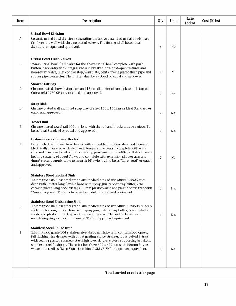
17
Item Description Qty Unit Rate
(Kshs) Cost (Kshs)
Urinal Bowl Division
A Ceramic urinal bowl divisions separating the above described urinal bowls fixed firmly on the wall with chrome plated screws. The fittings shall be as Ideal Standard or equal and approved. 2 No
Urinal Bowl Flush Valves
B 25mm urinal bowl flush valve for the above urinal bowl complete with push button, back entry with integral vacuum breaker, non-hold-open features and non-return valve, inlet control stop, wall plate, bent chrome plated flush pipe and rubber pipe connector. The fittings shall be as Docol or equal and approved.
1 No
Shower Fittings
C Chrome plated shower stop cork and 15mm diameter chrome plated bib tap as Cobra ref.107EC CP taps or equal and approved. 2 No
Soap Dish
D Chrome plated wall mounted soap tray of size: 150 x 150mm as Ideal Standard or equal and approved. 2 No.
Towel Rail
E Chrome plated towel rail 600mm long with the rail and brackets as one piece. To be as Ideal Standard or equal and approved. 2 No.
Instanteneous Shower Heater
F Instant electric shower head heater with embedded rod type sheathed element. Electrically insulated with electronic temperature control complete with wide rose and overflow to withstand a working pressure of upto 400kpa. It shall have a heating capacity of about 7.5kw and complete with extension shower arm and 4mm2 electric supply cable to neon lit DP switch, all to be as "Lorenzetti" or equal and approved
2 No
Stainless Steel medical Sink
G 1.6mm thick stainless steel grade 304 medical sink of size 600x4000x250mm deep with 3meter long flexible hose with spray gun, rubber tray buffer, 2No. chrome plated long neck bib taps, 50mm plastic waste and plastic bottle trap with 75mm deep seal. The sink to be as Leec sink or approved equivalent.
2 No.
Stainless Steel Embalming Sink
H 1.6mm thick stainless steel grade 304 medical sink of size 500x330x450mm deep with 3meter long flexible hose with spray gun, rubber tray buffer, 50mm plastic waste and plastic bottle trap with 75mm deep seal. The sink to be as Leec embalming single sink station model SSFD or approved equivalent.
1 No.
Stainless Steel Sluice Unit
I 1.6mm thick, grade 304 stainless steel disposal sluice with conical slop hopper, full flushing rim, drainer with outlet grating, sluice strainer, loose bolted P-trap with sealing gasket, stainless steel high level cistern, cistern supporting brackets, stainless steel flushpipe. The unit t be of size 600 x 600mm with 100mm P type waste outlet. All as "Leec Sluice Unit Model SLP/F-SK" or approved equivalent. 1 No.
Total carried to collection page

18
Item Description Qty Unit Rate (Kshs)
Cost (Kshs)
Stainless Steel Combined Disposal Hopper
A Stainless steel combined slop hopper, sink and worktop assembly with drainer comprising of hopper at left hand side with outlet grating, loose bolted S-trap with sealing gasket, vitreous china high level 7.5litre cistern, with valveless fittings and reversible chain pull, cistern supporting brackets, stainless steel flushpipe with spreader and clip and 2No.15mm lever handle taps. Complete with sink of size 500 x 400mm, 300mm diameter hopper and waste pipe to hopper. The fitting to be chrome plated 15mm lever action chrome plated extended bib taps. To be as "Twyfords Combined Disposal Hopper" or approved equivalent.
1 No.
AUTOPSY TABLE
B Autopsy table manufactured from Grade 304 Stainless steel of size 2100x750x1050mm high with the following characteristics:
.Downwards exhaust
.Electric adjustable height
.Solid stainless steel autopsy worktop
.Rectangular pedestal support
.Removable service access panel
.spray gun with 3m long flexible pipe
.Hot and cold water mixer
It shall be supported on floor mounted adjustable pedestal column. The fixture to be supplied complete with 50mm diameter waste fittings, supply fitting and flexible hose. To be as Leec Autopsy table model PMP-FT or approved equivalent. 1 No.
Paper/Towel Dispenser
C Paper/ towel dispenser for dispensing interfolded paper tissue suitable for hospital use. The dispenser shall include a casing having a narrow dispensing slot in the bottom surface. The dispenser should have a proper mechanism to prevent excessive quantities of tissue. The paper towel dispenser shall be in approved colour.
2 No.
Soap Dispenser
D Wall mounted soap dispenser with a capacity of about one litre having a press action soap release mechanism complete with fixing screws. Allow for initial soap supply. To be as Mediclinics or approved equivalent. 2 No.
Hand Drier
E Automatic "hands in" dual flow hand drier in white colour, operating on double infra-red automatic sensing system on both covers with heating element safety cut-out complete with a 30 seconds safety timer, plastic rawl plugs and fixing screws. The hand drier to have a heating capacity of 1.5kw and performance flow rate of 165m3/hr and air velocity of upto 410km/hr and to be of size 665x320x228mm deep It shall have a noise level below 72 dBA at 2m. It shall be as Mediclinics model M14A or approved equivalent.
2 No.
Total carried to collection page

19
Item Description Qty Unit Rate (Kshs)
Cost (Kshs)
INTERNAL PLUMBING WORKS
Supply, deliver and install PPR PN20 pipes, tubing and fittings as described and shown on the drawings. Rates must allow for all Metal/plastic threaded adaptors where required for the connection of sanitary fixtures, valves, sockets, sliding and fixed joints, support raceways, isolating sheaths, elastic materials, expansion arms and bends, crossovers, couplings, clippings, connectors, joints etc. as required in the running lengths of pipework and also where necessary, for pipe fixing clips, holder bats plugged and screwed for the proper and satisfactory functioning of the system. The pipes will be pressure tested before the plastering of wall commences and as per the manufacturers recommended testing pressures.
PPR PN20 PIPEWORK
A 20mm internal diameter pipework 36 Lm
B 25mm internal diameter pipework 72 Lm
C 32mm internal diameter pipework 96 Lm
D 40mm internal diameter pipework 36 Lm
Bends
E 20mm diameter bend 30 No.
F 25mm diameter bend 18 No.
G 32mm diameter bend 12 No.
H 40mm diameter bend 8 No.
Tees
I 20mm equal tee 2 No.
J 25mm equal tee 16 No.
K 32mm equal tee 12 No.
L 40mm equal tee 6 No.
Reducers
M 25 x 20mm diameter reducer 12 No.
N 32 x 20mm diameter reducer 3 No.
O 32 x 25mm diameter reducer 7 No.
P 40 x 32mm diameter reducer 3 No.
Q 40 x 25mm diameter reducer 1 No.
Total carried to collection page

20
Item Description Qty Unit Rate (Kshs)
Cost (Kshs)
Male/Female Adapters (Brass threaded)
A 20mm brass threaded adapter 14 No.
B 25mm brass threaded adapter 2 No.
C 32mm brass threaded adapter 2 No.
D 40mm brass threaded adapter 2 No.
Valves
E 32mm gate valve 4 No.
F 40mm gate valve 6 No.
G 40mm non-return valve 5 No.
Unions
H 32mm diameter pipe unions 8 No.
I 40mm diameter pipe unions 12 No.
Fresh Water Stand Pipe
J 15mm diameter bib tap suitable for connecting hose pipe complete with threaded adaptors. The tap to be complete with 5meter long 20mm diameter pipe, bends etc. The chrome plated bib tap to be as Cobra ref.107EC taps or equal and approved.
1 No
Excavations
K Excavate trench in hard soil 600mm wide and depth not exceeding 1000mm deep and average 750mm deep, prepare bed with red soil/marram of particle size not more than 20 mm to a depth of 750mm. Bed shall be approved by Engineer before laying of pipes. Fill with same material as above and compact in layers of 75 mm. Cart away surplus soil.
36 Lm
Pipe Sleeves
L 100mm diameter heavy duty PVC pipe sleeves for crossing over pathways and driveways. The sleeves will be encased in 150mm concrete sorround. 12 Lm
Water Supply Pipe
M 50mm galvanized steel pipes with fittings 72 Lm
Hand Spray
N 15mm diameter chrome plated hand spray complete with connections. 6 No.
O 15mm diameter chrome plated long neck bib taps 6 No.
Water Storage Tank
P Supply, deliver and install cylindrical plastic tank of capacity 920 litres and dimensions 1300x860mm high. The tank to be assembled complete with cover and having screwed connections for inlet, outlet, overflow, 32mm medium pressure ball valve, drain pipes and any other necessary item for its proper functioning. The tank shall be mounted on the roof slab and shall be as ROTO Model or approved equivalent.
2 No.
Total carried to collection page

21
Item Description Qty Unit Rate (Kshs)
Cost (Kshs)
Water Storage Tank
A Supply, deliver and install cylindrical plastic tank of capacity 5000 litres and dimensions 1840x1930mm high. The tank to be assembled complete with cover and having screwed connections for inlet, outlet, overflow, 32mm medium pressure ball valve, drain pipes and any other necessary item for its proper functioning. The tank shall be as ROTO Model or approved equivalent. 1 No.
Water Booster Pumpset
B Set of automatic electrically driven twin booster pumpset. The pumpset shall be complete with control panel and shall compose of one duty and the other one standby with automatic changeover, capable of delivering 3.5m3 per hour against a head of 35 meters. The pumpset shall be complete with 1No. 64 litres pressure vessels and all accessories required for proper and satisfactory operation. It includes pressure switches, time delay switch, a switch to protect against dry run, timer, gate valves, non-return valves, flow switch and 50mm diameter strainer. The pump to be as Grundfos CM5-6 model or approved equivalent. Pump to be installed on galvanised mild steel frame with approved paint.
1 Set
Control and Control Panel
C Control panel for above pumps with contactors, over voltage and under voltage protection relays, MCBs, phase failure protection, timer, 12 meters long float switch control cable to the tanks, start/stop push buttons and indicator lights. All these shall be housed in a lockable cabinet (with integral isolator) made from SWG 18 mild steel sheet that is oven powder coated. There shall also be an adjustable time delay switch to ensure pumping cycles are controlled to not more than 6 per hour. It should include a change-over switch to enable the pumps to work alternately.
1 Item
Associated Electrical Works
D Allow for electrical works wiring and fitting to all pumps, control panel and float switches, from isolator provided by others with 3 metres distance.
1 Item
Water Connection
E Allow for water connection to the existing water line by excavating, teeing off from the existing water line and making good after connection.
1 Item
Water Sterilization
F Allow for water water sterilization after connection by chlorination 1 Item
Testing and Commissioning
G Allow for setting to work, testing and commissioning of the plumbing installation to the satisfaction of the Project Engineer 1 Item
Total carried to Collection Page

22
Item Description Qty Unit
Rate (Kshs)
Cost (Kshs)
FOUL WATER INTERNAL DRAINAGE
Supply, deliver and install the following UPVC, MUPVC, soil and waste systems respectively to B.S 5255 with fittings fixed to Manufactures Printed instructions and manufactured by reputable manufacturers. Tenderers must allow in their pipework prices for all the couplings, clippings, connectors, joints etc. as required in the running lengths of pipework and also where necessary, for pipe fixing clips, holder bats plugged and screwed for the proper and satisfactory functioning of the system.
MuPVC and uPVC Waste and Soil pipework
A 100mm diameter heavy gauge golden brown UPVC pipe 72 Lm
B 100mm diameter heavy gauge grey mUPVC pipe 24 Lm
C 50mm diameter waste pipe 48 Lm
D 40mm diameter waste pipe 36 Lm
E 32mm diameter waste pipe for AC drainage 42 Lm
Bends
F 100mm diameter long radius bend 4 No.
G 100mm diameter short radius bend 4 No.
H 100mm diameter bend with access 2 No.
I 100mm diameter sweep bend 3 No.
J 50mm diameter sweep bend 18 No.
K 40mm diameter sweep bend 24 No.
Tees
L 100mm diameter sweep tee 2 No.
M 50mm diameter sweep tee 8 No.
N 40mm diameter sweep tee 12 No.
O 32mm diameter sweep tee 14 No.
Reducers
P 100 x 50mm diameter reducer 1 No.
Q 50 x 40mm diameter reducer 6 No.
R 40 x 32mm diameter reducer 8 No.
Access Caps
S 100mm diameter access cap 4 No.
T 50mm diameter acces cap 6 No.
U 40mm diameter access cap 7 No.
Total carried to collection page

23
Item Description Qty Unit Rate (Kshs)
Cost (Kshs)
Boss Connectors
A 100 x 50mm diameter boss connector 4 No.
B 100 x 40mm diameter boss connector 4 No.
Single Branches
C 100mm diameter single branch 1 No.
WC Connectors
D 100mm diameter WC connector 4 No.
Traps
E 100 x 50mm diameter floor trap and plastic grating 7 No.
F 100 x 100mm diameter floor trap and stainless steel grating 7 No.
G Allow for a standard 300 x 300 x 450mm masonry gully trap complete with concrete cover.
6 No.
Weathering Slates and Vent Cowls
H 100mm diameter weathering slate and apron. 2 No.
I 100mm diameter vent cowl 2 No.
Excavations
J Excavate trench in hard soil/murram 600mm wide and depth not exceeding 1000mm deep and average 750mm deep, prepare bed with red soil/marram of particle size not more than 20 mm to a depth of 750mm. Bed shall be approved by Engineer before laying of pipes. Fill with same material as above and compact in layers of 75 mm. Cart away surplus soil.
72 Lm
MuPVC Rainwater Pipework
K 100mm diameter heavy gauge grey mUPVC pipe 112 Lm
L 100mm diameter bend 24 No.
M 100 x 50mm diameter boss connector 8 No.
N 100 x 50mm diameter floor trap and grating 12 No.
O 100mm diameter plastic fulbora 7 No.
Pipe Sleeves
P 100mm diameter heavy duty PVC pipe sleeves for crossing over columns and beams. 6 Lm
Inspection Chambers
Q Construct Inspection chamber size 600x450mm and averaging 950mm deep constructed in 100mm thick concrete bass (1:3:6), approved 150mm block sides rendered all around in cement and sand(1:4). It shall have an approved heavy duty plastic cover and frame as manufactured by EA Foundry Works. Include all necessary excavations, disposal and form work. To be as manhole type 'A'
9 No.
R Ditto but type B 3 No.
Total carried to collection page

24
Item Description Qty Unit Rate (Kshs)
Amount (Kshs)
Drainage/Sewer Connection
P Allw for drainage connection to the existing sewer line or the septic tank. 1 Item
Drainage Connectin Pipes
K 150mm diameter heavy gauge golden brown UPVC pipe 72 Lm
Portable Fire Extinguishers
Supply, deliver, install, test and commission the following LPCB approved portable fire extinguishers and conforming to BS EN 3 / BS 1449.They shall be as manufactured by Naffco or approved equivalent.
Carbon Dioxide Gas Fire Extinguisher
A 5kg carbon dioxide gas portable fire extinguisher complete with pressure gauge, initial charge and mounting brackets. 2 No
Dry Chemical Powder Fire Extinguisher
B 9kg dry chemical podwer portable fire extinguisher complete with pressure gauge, initial charge and mounting brackets. 2 No
Manual Alarm Bell
C 9" (225mm) manual operated alarm bell (Gong) 2 No
Fire Notices
D Allow for fire signage for the hose reel system, fire exits and fire instructions as as described in the particular specifications and to the Project Engineer's approval. 2 No
Total Carried Forward to Summary Page

25
COLLECTION PAGE FOR INTERNAL PLUMBING AND DRAINAGE WORKS
Item Description Amount (Kshs)
1 Total carried forward from page G-15 …………………………
2 Total carried forward from page G-16 …………………………
3 Total carried forward from page G-17 …………………………
4 Total carried forward from page G-18 …………………………
5 Total carried forward from page G-19 …………………………
6 Total carried forward from page G-20 …………………………
7 Total carried forward from page G-21 …………………………
8 Total carried forward from page G-22 …………………………
9 Total carried forward from page G-23 …………………………
Total Cost for Sanitary, Plumbing, Fire Fighting and Drainage Works Carried to Forward to Mechanical Works Summary Page G-25

26
PROPOSED FUNERAL HOME AT GATUNDU LEVEL V HOSPITAL
SUMMARY PAGE FOR MECHANICAL WORKS
Item Description Total Cost (Kshs)
1 Total for Preliminaries and General Items frm Page G-6 …….
2 Total Carried Forward from Collection Page G-7 for Air Conditioning Works …….
3 Total Carried Forward from Collection Page G-11 for Mortuary Coldrooms
…….
4 Total Carried Forward from Collection Page G-14 for Mechanical Ventilation …….
5 Total Carried Forward from Collection Page G-24 for Sanitary Fittings Plumbing, Fire Fighting and Drainage Works
…….
6 Contingency Sum
……. 1,000,000.00
Total for Mechanical Works Carried to Form of Tender
Amount in words…………………………………………………………………………………….....................................
……………………………………………………………………………………………..……………………………………....
Tenderer's Name and Stamp ………………………………………..………………….……………………………………………………………..…………………………………………………………………………………..………………………………………………………………..
Address ……………………………………………………………………………………...……………...……..……………………...………………………………………………………...……………………………………………………………………………….
Period To Execute The Works …….……………………………….……....………………………………………………….
Tenderer’s V.A.T No ….………………………………………………….……………………………………………………...
Tenderer’s P.I.N No ….…………………………………………………………………………………...……………………..
Tenderer's Signature …………………………………………...….… Date………………….………………………...………
Witness Signature ……………………………………………….…... Date………………….………………………..………

27
SECTION H:
TECHNICAL SCHEDULE OF ITEMS TO BE SUPPLIED

28
CONTENTS
CLAUSE No. PAGE
1. GENERAL NOTES TO THE TENDERER………………………. (i)
2. TECHNICAL SCHEDULE…………………………………………. H-1
3. TECHNICAL DATA …………………………………………. H-2
(i)

29
TECHNICAL SCHEDULE
1. General Notes to the Tenderer
1.1 The tenderer shall submit technical schedules for all materials and equipment upon which he
has based his tender sum.
1.2 The tenderer shall also submit separate comprehensive descriptive and performance details
for all plant apparatus and fittings described in the technical schedules. Manufacturer’s
literature shall be accepted. Failure to comply with this may have his tender disqualified.
1.3 Completion of the technical schedule shall not relieve the Contractor from complying with
the requirements of the specifications except as may be approved by the Engineer.
H-1

30
TECHNICAL SCHEDULE
The tenderer must complete in full the technical schedule. Apart from the information required in the technical
schedule, the tenderer MUST SUBMIT comprehensive manufacturer’s technical brochures and performance
details for all items listed in this schedule (fill forms attached).
ITEM DESCRIPTION MANUFACTURER COUNTRY
OF ORIGIN
REMARKS
(Catalogue
No. etc.)
A
B
C
D
E
F
G
H
I
J
Refrigerated Body Storage Cabinets
Mortuary Trolley
Post Mortem Table
Air Conditioners
Fans
Water Closets
Wash Hand Basins
Pumps
Sluice Unit
Water Tanks
Catalogue must be attached for all the Items in the schedule of material above
H-2

31
SECTION I:
STANDARD FORMS
NOTE:
ALL FORMS IN THIS SECTION MUST BE FILLED AS THEY SHALL BE PART
OF THE EVALUATION CRITERIA

32
CONTENTS OF SECTION I
TITLE PAGE
1. Performance Bank Guarantee................................................................ I/1
2. Tender Questionnaire............................................................................. I/2
3. Confidential Business Questionnaire...................................................... I3–I/4
4. Key Personnel........................................................................................ I/5
5. Schedule of Contracts completed in the last eight (8) years................... I/6
6. Schedule of on-going projects................................................................. I/7
7. Schedule of major items of contractor’s equipment. …………………. I/8
8. Financial reports for the last five (5) years ………………………………… I/9
9. Evidence of Financial Resources. …………………………………………. I/10
10. Name, Address and Telephone, Telex and Facsimile of Banks. ………. I/11
11. Draft Program of Works ………………………………………… I/12
12. Details of Litigation or Arbitrations. ……………………………………… I/13
NOTE:
1.0 Tenderers must duly fill these Standard Forms as a mandatory requirement.
2.0 Any tender returned with unfilled Standard Forms shall be considered non -
responsive and shall automatically be disqualified.

33
PERFORMANCE BANK GUARANTEE
To: County Secretary
P.O. Box 2344-00900,
KIAMBU
Dear Sir,
WHEREAS. ………………………………………(Hereinafter called “the Contractor”) has undertaken, in
pursuance of Contract No. ………………………… Dated ……………… to execute
………………………………………………… (hereinafter called “the Works”);
AND WHEREAS it has been stipulated by you in the said Contract that the Contractor shall furnish you with a
Bank Guarantee by a recognized bank for the sum specified therein as security for compliance with his
obligations in accordance with the Contract;
AND WHEREAS we have agreed to give the Contractor such a Bank Guarantee:
NOW THEREFORE we hereby affirm that we are the Guarantor and responsible to you, on behalf of the
Contractor, up to a total of:
Kshs. …………………………………. (Amount of Guarantee in figures)
Kenya Shillings. ……………………………………………………………………………………
………………………………………………………………(Amount of Guarantee in words),
and we undertake to pay you, upon your first written demand and without cavil or argument, any sum or sums
within the limits of Kenya Shillings ……………………..
………………………………………………………………. (Amount of Guarantee in words) as aforesaid
without your needing to prove or to show grounds or reasons for your demand for the sum specified therein.
We hereby waive the necessity of your demanding the said debt from the Contractor before presenting us with
the demand.
We further agree that no change, addition or other modification of the terms of the Contract or of the Works to
be performed there under or of any of the Contract documents which may be made between you and the
Contractor shall in any way release us from any liability under this Guarantee, and we hereby waive notice of
any change, addition, or modification.
This guarantee shall be valid until the date of issue of the Certificate of Completion.
SIGNATURE AND SEAL OF THE GUARANTOR …………………………………….………
Name of Bank …………………………………………………………………………….
Address …………………………………….………………………………….……….…
Date ……………………………………….………………………………………………
I/1

34
TENDER QUESTIONNAIRE
Please fill in block letters.
1. Full names of Tenderer:
………………………………………………………………………………………
2. Full address of Tenderer to which tender correspondence is to be sent (unless an agent has been
appointed below):
………………………………………………………………………………………
3. Telephone number (s) of Tenderer:
………………………………………………………………………………………
4. Telex/Fax Address of Tenderer:
………………………………………………………………………………………
5. Name of Tenderer’s representative to be contacted on matters of the tender during the tender period:
………………………………………………………………………………………
6. Details of Tenderer’s nominated agent (if any) to receive tender notices. This is essential if the
Tenderer does not have his registered address in Kenya (name, address, telephone, telex):
………………………………………………………………………………………
………………………………………………………………………………………
_______________________
Signature of Tenderer
I/2

35
CONFIDENTIAL BUSINESS QUESTIONNAIRE
You are requested to give the particulars indicated in Part 1 and either Part 2 (a), 2 (b) or 2(c) and (2d)
whichever applies to your type of business.
You are advised that it is a serious offence to give false information on this Form.
Part 1 – General
Business Name ………………………………………………………………………
Location of business premises: Country/Town…………………………………….
Plot No……………………………………… Street/Road …………………………
Postal Address……………………………… Tel No………………………………..
Nature of Business …………………………………………………………………..
Current Trade Licence No…………………… Expiring date…………………
Maximum value of business, which you can handle at any time:
Kenya Shillings………………………………………………………………………
Name of your bankers………………………………………………………………
Branch…………………………………………………………………………………
Part 2 (a) – Sole Proprietor
Your name in full…………………………………… Age…………………………
Nationality………………………………… Country of Origin…………………

36
Citizenship details …………………………………………………………………
Part 2 (b) – Partnership
Give details of partners as follows:
Name in full Nationality Citizenship Details
Shares
1. ………………… ………………. ……………………….. ……..
2. ………………… ………………. ……………………….. ………
3. ………………… ………………… ………………………… ………
4. ………………… ………………… ………………………… ………
I/3

37
Part 2(c) – Registered Company
Private or Public ……………………………………………………………………………
State the nominal and issued capita of the company:
Nominal KShs. …………………..
Issued KShs. …………………..
Give details of all directors as follows:
Name in full Nationality Citizenship Details* Shares
1. ……………….. …………… ……………………….. ………..
2. ……………….. …………… ……………………….. ………..
3. ……………….. …………… ……………………….. ………..
4. ……………….. …………… ……………………….. ………..
Part 2(d) Interest in the Firm:
Is there any person/persons in the employment of the Government of Kenya WHO has interest in this firm?
Yes/No ……. (Delete as necessary)
I certify that the above information is correct.
…………………........ ……………………....... …………………......
Title Signature Date
* Attach proof of citizenship must be provided
I/4

38
KEY PERSONNEL
Qualifications and experience of key personnel proposed for administration and execution of the
Contract.
POSITION NAME YEARS OF
EXPERIENCE
(GENERAL)
YEARS OF
EXPERIENCE IN
PROPOSED
POSITION
1.
2.
3.
4.
5.
6.
7.
8.
9.
10.
I certify that the above information is correct.
…………………….…....... …………………...... …....... ……………....
Title Signature Date
I/5

39
CONTRACTS COMPLETED IN THE LAST FIVE (5) YEARS
Work performed on works of a similar nature, complexity and volume over the last 5 years.
PROJECT NAME NAME OF CLIENT TYPE OF WORK
AND YEAR OF
COMPLETION
VALUE OF
CONTRACT
(Kshs.)
I certify that the above works were successfully carried out and completed by ourselves.
…………………………. ……………………………….. ……………………….
Title Signature Date
I/6

40
SCHEDULE OF ON-GOING PROJECTS Details of on-going or committed projects, including expected completion date.
PROJECT
NAME
NAME OF
CLIENT
CONTRACT
SUM
%
COMPLETE
COMPLETION
DATE
I certify that the above works are currently being carried out by ourselves.
……………………… …………….………………… ……………………….
Title Signature Date
I/7

41
SCHEDULE OF MAJOR ITEMS OF CONTRACTOR’S EQUIPMENT PROPOSED FOR
CARRYING OUT THE WORKS
ITEM OF
EQUIPMENT
DESCRIPTION, MAKE AND
AGE (Years)
CONDITION (New,
good, poor) and
number available
OWNED, LEASED
(From whom?), or to
be purchased (From
whom?)
I/8
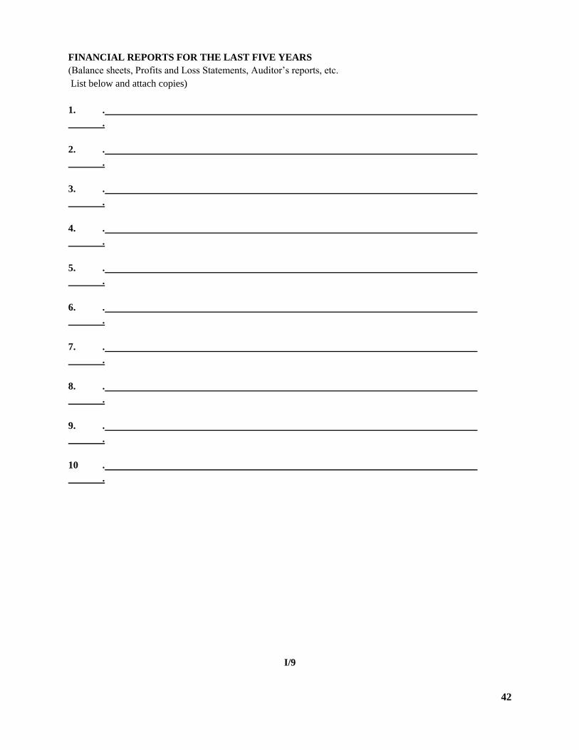
42
FINANCIAL REPORTS FOR THE LAST FIVE YEARS
(Balance sheets, Profits and Loss Statements, Auditor’s reports, etc.
List below and attach copies)
1. .
.
2. .
.
3. .
.
4. .
.
5. .
.
6. .
.
7. .
.
8. .
.
9. .
.
10 .
.
I/9

43
EVIDENCE OF FINANCIAL RESOURCES TO MEET QUALIFICATION REQUIREMENTS
(Cash in Hand, Lines of credit, e.t.c. List below and attach copies of supportive documents.)
1. . .
2. .
.
3. .
.
4. .
.
5. .
.
6. .
.
7. .
.
8. .
.
9. .
.
10 .
.
I/10

44
NAME, ADDRESS AND TELEPHONE, TELEX AND FACSIMILE OF BANKS
(This should be for banks that may provide reference if contacted by the employer)
NAME ADDRESS TELEPHONE TELEX FACSIMILE
I/11

45
DRAFT PROGRAM OF WORKS IN THE FORM OF A BAR CHART
I/12
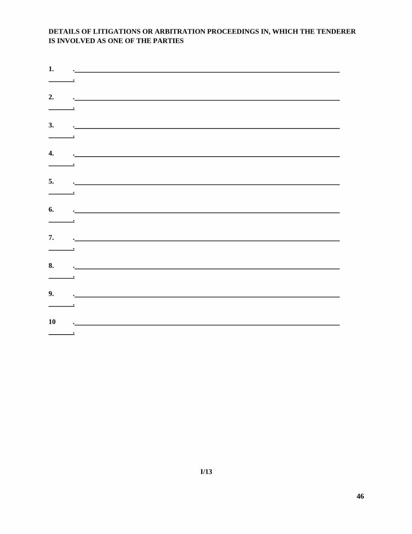
46
DETAILS OF LITIGATIONS OR ARBITRATION PROCEEDINGS IN, WHICH THE TENDERER
IS INVOLVED AS ONE OF THE PARTIES
1. .
.
2. .
.
3. .
.
4. .
.
5. .
.
6. .
.
7. .
.
8. .
.
9. .
.
10 .
.
I/13
Related Documents