Synchronous condensers in mining projects Improving power system stability and short-circuit power Reprint from Mining Engineering, January 2015, Vol. 67, No. 1 Remote project locations and the need for long transmission lines to provide electrical power for mining operations, often result in poor network power quality and low short-circuit capacity of a mine. A solution to cope with this issue, is the installation of synchronous condensers together with power factor correction and harmonic filter systems, designed to fit the individual mine requirements.

Welcome message from author
This document is posted to help you gain knowledge. Please leave a comment to let me know what you think about it! Share it to your friends and learn new things together.
Transcript

Synchronous condensers in mining projects Improving power system stability and short-circuit power
Reprint from Mining Engineering, January 2015, Vol. 67, No. 1
Remote project locations and the need for long transmission lines to provide electrical power for mining operations, often result in poor network power quality and low short-circuit capacity of a mine. A solution to cope with this issue, is the installation of synchronous condensers together with power factor correction and harmonic filter systems, designed to fit the individual mine requirements.


Reprint from Mining Engineering, January 2015, Vol. 67, No. 1 | Synchronous condensers in mining projects 3
38 January 2015 Mınıng engıneerıng www.miningengineeringmagazine.com
Technical Papers
IntroductionTo ensure the efficient utilization of
electrical power for mining operations, power factor correction and harmonic filter systems have become unavoidable electrical subsystems due to their two major advantages:
• Improvement of the plant power factor by limiting the amount of reactive power supplied by the utility, thereby eliminating the payment of penalties to the utility and any associated costs. As a result, significant cost savings can be achieved.
• Effective filtering of harmonics being produced within the plant and imported from the supplying high-voltage network. In this way, PFC & HFSs protect expensive and critical plant equipment and other consumers of electrical energy supplied by the same grid.
Plant operation becomes critical when a weak network has to supply a big plant where significant harmonic generating loads are installed. In such cases synchronous condensers could be a promising solution.
Importance of maintaining plant voltage
The most critical events associated with voltage level are a short circuit in the plant (causing a voltage collapse), and a sudden trip of big plant loads (causing a voltage rise).
The only supportive action in the case of a short circuit is a rapid disconnection of the plant area where the short circuit occurred. However, until a successful disconnection is managed, the voltage stays fully
depressed and there is no help or remedy in this regard. In contrast to this, a sudden voltage rise due to the trip of a big load within or outside the plant can be reduced by a synchronous condenser. A properly designed synchronous condenser with the support of optimized control logic for the synchronous condenser and PFC & HFS can prevent further load trips due to overvoltage.
A mining plant typically has a significant amount of electrical equipment with varying functions reacting differently in overvoltage situations. However, there are process-critical loads that should be kept in operation to ensure the whole production operation is not interrupted. An important example of such a critical load process is the SAG and ball mills in the grinding area. SAG and ball mills driven by cycloconverters have two overvoltage protection levels that have to be generally observed as part of the protection concept. For overvoltages between 112% and 115% of the nominal voltage, a cycloconverter will be tripped after 250 milliseconds and for overvoltages above 115%, the trip will be instantaneous.
Impact of usingsynchronous condensers for power system stability and improvement of short-circuit
power in mining projectsby M. Nambiar and Z. Konstantinovic
M. Nambiar and Z. Konstantinovic are engineering manager and senior engineer, respectively, at ABB Switzerland, Zurich, Switzerland. Paper number TP-13-060. Original manuscript submitted November 2013. Revised manuscript accepted for publication August 2014. Discussion of this peer-reviewed and approved paper is invited and must be submitted to SME Publications by April 30, 2015.
abstract ■ Due to the remote locations of mining projects and the need for long transmission lines to provide electrical power, mining sites often operate with poor network power quality and low short-circuit capacity. To cope with this situation, more and more mining operators are considering the installation of appropriately designed synchronous condensers together with power factor correction and harmonic filter systems (PFC & HFS). The installation of such power quality equipment is viewed as a technological advancement in the mining application. an adequate level of short-circuit power is essential and has to be ensured for the safe and reliable operation of especially large cycloconverter-driven gearless mill drive systems (GMDs) used for grinding. This paper explores the impact, technical advantage and reasoning for the selection of this advanced hybrid technology to cope with the power system challenges of future mining projects. It also delves into the potential problems and how to address them.
Mining Engineering, 2015, Vol. 67, no. 1, pp. 38-44. Official publication of the Society for Mining, Metallurgy & Exploration Inc.
4 Synchronous condensers in mining projects | Reprint from Mining Engineering, January 2015, Vol. 67, No. 1
www.miningengineeringmagazine.com Mınıng engıneerıng january 2015 39
Technical Papers
The primary goal is to not let voltage rise above 115% at any time. It is obvious that the bus voltage level prior to the trip of a large load will influence the voltage level after the trip. The voltage rise itself is dictated by the tripping load and the strength of the supplying network. The absolute value of bus voltage after the load trip will be:
voltage after trip = voltage before trip + voltage rise due to load disconnection
It is noticed that weak networks and big loads, both typical of mining plants, will often result in voltages far above 115% after a load trip. This would lead to the tripping of all other mills driven by cycloconverters, and most probably the further cascade tripping of other electrical equipment throughout the plant.
Advantages of using synchronous condensers
A synchronous condenser is essentially a common synchronous motor that runs idle without any connected load at the drive end (ABB, 2013). Like a generator, it can be over-excited or under-excited by varying its field current. By varying the excitation, the magnitude of the internal voltage source will change. Using a synchronous condenser has a number of advantages:
• By changing the excitation of the synchronous condenser, stepless export and import of reactive power are possible (capacitive and inductive power).
• By varying the amount and direction (import/export) of reactive power, a synchronous condenser provides a stepless and effective control of bus voltage that is much faster and finer than with a classical on load tap changer (OLTC) or the switching of a PFC & HFS. In contrast to various static equipment for voltage stabilization (equipment without moving parts), a synchronous condenser can provide substantial support with its considerable short overload capability (150% or even more of its rated current) and for longer with its fully rated capacity (export of reactive power), even under serious low-voltage conditions. Equipment such as static var compensators (SVCs) or PFC & HFSs lose a lot of their capability to deliver reactive power (power is proportional to the square of line voltage) just under the critical condition of low voltage, when the maximum possible support is desperately needed by the network system (Teshmont, 2005; Teleke et al., 2008).
• A synchronous condenser supports the supply network during transient voltage excursions by reacting within milliseconds with countermeasures to the voltage changes: by delivering capacitive power as voltage drops, or delivering inductive power as voltage rise.
• In contrast to some other equipment, a synchronous condenser does not cause any transients or notching on the grid (Becker, 1992) during operation.
• A synchronous condenser does not produce any notable harmonics (Kubota et al., 1972) and can partly absorb harmonics without amplifying any of them.
• In contrast to capacitors and passive harmonic filters, a synchronous condenser does not cause any additional parallel resonance with the supplying network.
• A synchronous condenser decreases effective network impedance, which moves all existing parallel resonances toward higher frequencies. This unique feature is often the triggering point influencing the decision to install synchronous condensers, as there is mostly no other economical means to move the lower frequency parallel resonance away from line frequency. Parallel resonance, which is close to line frequency, may cause serious problems for the stability of the electrical supply, for loads driven by rotating machines and for turbine generators (shaft, blades) (Moharana, 2012). This risk is elevated in plants where in addition to common harmonics the so-called inter-harmonics are present as well (for example, where cycloconverters are used to run the SAG and ball mills).
Some concerns regarding the use of synchronous condensers
In spite of their many advantageous features not all mining plants have synchronous condensers – why? As is often the case, the main reason is cost. Aside from capital investment in the synchronous condenser itself, there are maintenance costs and costs related to thermal losses. Maintenance is basically the same as for other large motors in the plant. Synchronous-condenser losses are generally about 1-3% of the rated power (Peterson, 1993; Power System
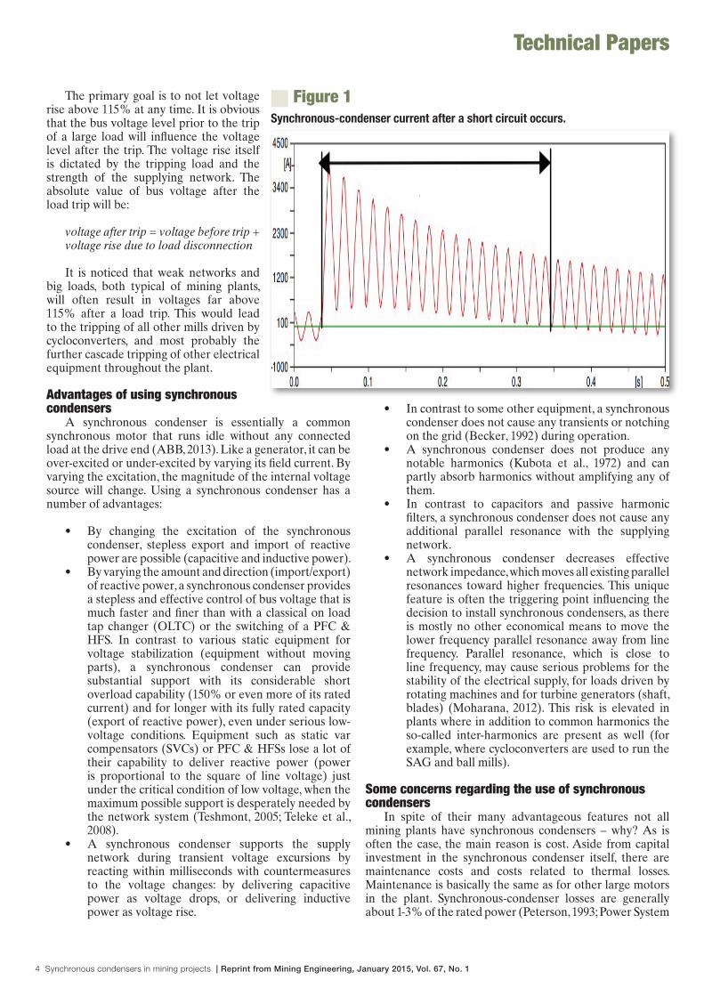
Synchronous-condenser current after a short circuit occurs.
Figure 1

Reprint from Mining Engineering, January 2015, Vol. 67, No. 1 | Synchronous condensers in mining projects 5
40 January 2015 Mınıng engıneerıng www.miningengineeringmagazine.com
Technical Papers
Operation, 2012). Being mostly operated at no load, realistic losses can be estimated at 1.3-1.5% of rated synchronous-condenser power.
• The increased short-circuit power due to the installation of a synchronous condenser may require additional measures to ensure that the bus system and the associated switchgears are rated to withstand the increased short-circuit current.
• A short circuit near the synchronous condenser could lead to the possible missing out of current-zero-crossing right after the short circuit has occurred. The circuit breaker can only break a fault current when the alternating current crosses the zero-value. A synchronous-condenser fault current is composed of a DC offset and an AC symmetrical component; if the DC component is sufficiently large, there will be a long delay before the current crosses the zero value, which could therefore lead to a long delay before the circuit breaker can break the fault current (see Fig. 1).
The time constant of this decay of fault current is determined by the X/R ratio at the fault location. In the case of high X/R ratio, this decay can be extremely large up to hundreds of milliseconds, which could impose a significant problem for synchronous-condenser circuit breakers and for the equipment where the short circuit occurred (Gallagher et al., 2010). The worst-case scenario is when a two-phase fault develops into a three-phase fault while synchronous condensers are operating in an under-excited condition (when the plant load condition is capacitive) and there is negligible resistance in the fault path.
Optimizing the utility of synchronous condensersOnce the decision has been made to install one or
more synchronous condensers in a plant, the synchronous condenser should be fully integrated into the overall electrical system, including its advanced control system, in order to maximize its utilization and minimize its disadvantages and/or risks.
Besides increased system short-circuit power, which may be the main criterion for the selection of synchronous condensers, the following opportunities should be taken into consideration as well:
• Optimization of PFC & HFS design to realize significant cost savings: By carefully analyzing different plant and network operating and critical scenarios, it may be sufficient to have a smaller and/or simpler PFC & HFS through the smart usage of a synchronous condenser.
• Transient support of plant voltage: This can be ensured by choosing appropriate parameters for the rated power, overload characteristics, impedances and time constants of the synchronous condenser, as well as for the rated power and short-circuit impedance of the intermediate transformer (if any is needed) for the synchronous condenser.
• Smooth voltage control for special situations and procedures like mill starting: This can be realized by
the proper operational coordination of big loads, the PFC & HFS and the synchronous condenser.
• Reduction of switching actions of PFC & HFS: This can be achieved by smart control and coordination between the control systems of the PFC & HFS and the synchronous condenser.
Maintaining plant voltage within limits and avoiding load trips
With a synchronous condenser in operation, a voltage rise due to a load trip will no longer be a sudden one-step occurrence. Instead it will be gradual, reaching the final value after several seconds. The magnitude of the final value will be lower than what it would be without a synchronous condenser in operation. This is typical of synchronous condensers as a voltage source with variable inner impedance (Teshmont, 2005). It occurs when no external control of the synchronous condenser has been applied. With control of the synchronous-condenser excitation voltage, the behavior will be modified to actively fulfill the goals defined for the control system. However, the time constant of the synchronous-condenser system is relatively long (from slightly less than one second to a few seconds) compared with the time constant of an SVC or Statcom system. Therefore the synchronous-condenser excitation control will not be very effective immediately after the load trip and only the typical behavior without active control as described above will determine the initial voltage rise at the connected bus.
With the synchronous condenser in operation, the final bus voltage after the load trip is mainly influenced by the following factors/parameters:
• Short-circuit power of the supplying network: lower short circuit power leads to higher voltage rise.
• Characteristics of the synchronous condenser, like rated power and subtransient impedance: higher rated power and/or lower impedance leads to lower voltage rise.
• Characteristics of the intermediate transformer for the synchronous condenser, like rated power and short-circuit impedance: higher transformer power and/or lower impedance leads to lower voltage rise.
• Amount of capacitive power for the PFC & HFS connected to the network during the event of a load trip: higher capacitive power connected leads to higher voltage rise.
• Rating of the load that is being disconnected from the network: higher-capacity load trip leads to higher voltage rise.
• Bus voltage prior to load trip: lower bus voltage before leads to lower voltage after the trip.
• Internal voltage of the synchronous condenser: lower internal voltage leads to lower voltage after the trip.
From the above, it is evident that not only the physical characteristics of hardware (supply network, load, synchronous condenser, intermediate transformer, PFC & HFS) determine whether the tripping of one load will lead to subsequent trips of further loads due to voltage rise, but also

6 Synchronous condensers in mining projects | Reprint from Mining Engineering, January 2015, Vol. 67, No. 1
www.miningengineeringmagazine.com Mınıng engıneerıng january 2015 41
Technical Papers
the control system logic. The control system logic determines how much capacitive power is to be connected in the plant, and what bus voltage and internal synchronous-condenser voltage should be maintained during critical operations.
Example of synchronous condensers applied in a large mineral-processing plant with weak supply network
This example is based on an actual synchronous-condenser installation for power system improvements in a mining project in South America. The plant is located at the end of a long 220-kV/60-Hz overhead transmission line with minimum short-circuit power of only 220 MVA, feeding a 120-MW approximately full load. Two main transformers, each 75/100/125-MVA with 9% impedance, supply loads on two main 23kV busbars. One SAG (18 MW) and two ball mills (2x15 MW) are driven by cycloconverters. In order to achieve the target power factor at 220 kV approximately 70 MVAr capacitive power is required. This capacitive power has been split into two identical PFC & HFSs connected to each of the two main 23-kV busbars. Each 35-MVAr PFC & HFS is designed as a group of seven harmonic filter units, tuned for different harmonic orders (2nd, 3rd, 4th, 5th, 7th, 11th and 13th). These seven harmonic filter units are switchable in four steps/groups:
• Group A with total 11.6 MVAr capacitive power: 2nd and 3rd filter, each with 5.8 MVAr
• Group B with total 8.6 MVAr capacitive power: 4th filter with 2.8 MVAr and 5th filter with 5.8 MVAr
• Group C with total 8.8 MVAr capacitive power: 7th
filter with 3.0 MVAr and 11th filter with 5.8 MVAr• Group D with total 5.8 MVAr capacitive power:
only 13th filter with 5.8 MVAr
The plant is designed to operate even with only one of the two transformers feeding the complete load having the tiebreaker between two main busbars closed.
The simplified single-line diagram in Fig. 2 shows the equipment together with the two synchronous condensers that were introduced at a later stage after a detailed system analysis was done using the NEPLAN power system engineering tool. The major problem identified was the combination of a weak supply network and the large amount of capacitive power needed to keep the power factor of the plant at its targeted value of 0.95 lagging or higher. Due to these two physical determinants, the existence of one strong parallel resonance with frequency close to the line frequency (as low as 71 Hz) was noticed during the power simulation calculations. Together with strong inter-harmonics from cycloconverters, which may hit this parallel resonance, it could result in the excitation of mechanical oscillations in rotating machines and driven equipment (Camay, 1983). If one of the rotating machines with a driven load has a natural resonant frequency at or near to 11 Hz (71 – 60 = 11) it can lead to problems and even mechanical damages. Moreover, if the affected rotating machine is one of the generators within the supply network it can even lead to damage of the shaft or turbine blades, thus resulting in instability of the power network. The critical frequency range for electromechanical oscillations in big rotating machines mostly range from 14 to 35 Hz (Elfayoumy and Moran, 2003; Tsai et al., 2006),
Single-line diagram of the mining project in South America with two synchronous condensers and PFC & HFS installed.
Figure 2

Reprint from Mining Engineering, January 2015, Vol. 67, No. 1 | Synchronous condensers in mining projects 7
42 January 2015 Mınıng engıneerıng www.miningengineeringmagazine.com
Technical Papers
but frequencies lower than 14 Hz or higher than 35 Hz have also been reported. The frequency range of mechanical oscillations of 14-35 Hz translates into a 74-95 Hz range for the critical electrical parallel resonance of the 60-Hz supply system (64-85 Hz in the case of 50-Hz supply systems).
The mine operators are made aware in cases where the parallel resonance with lowest frequency slips below 95 Hz (85 in 50-Hz networks). In more serious cases of parallel resonance with lowest frequency below 90(80) Hz it is recommended to introduce synchronous condensers.
Network impedance and parallel resonance. The following sections describe the results of a simulation study conducted to verify the influence of synchronous condensers on the power system network. The study was conducted using the NEPLAN power system engineering software tool. Figure 3 presents impedance versus frequency, seen from the 23-kV main busbars tied together (red line). The black line represents the same network impedance but without harmonic filters and without any capacitances within or outside the plant. In this case synchronous condensers are not energized.
The following observations can be made from Fig. 3: The maximums and minimums visible in the red line are mostly a result of the interplay of harmonic filters in the plant and the impedance of the supply network. Some of them, however, come from the high-voltage network itself. All but the one maximum close to the line frequency of 60 Hz are below the black line, meaning that for these frequencies no amplification of harmonics produced by plant loads will occur. However, for frequencies where the red line is
above the black line, harmonics and inter-harmonics will be amplified. The amplification ratio is given approximately by the ratio of impedance-amplitudes (red and black lines) at the given frequency.
At the frequency of the highest peak (71 Hz) the amplification ratio is above 10. Physically this means that, for each 1 ampere current being produced by any of nonlinear loads at 71 Hz, more than 10 amperes will flow into the network. This leads to:
• High distortions of 23-kV voltage where some loads driven by rotating machines may start to oscillate.
• High current flowing towards the supply network where mechanical resonances in generators may be excited.
At 60 Hz, we see that the impedance with harmonic filters (red line) is about three times higher than without them (black line). Physically this means that, with harmonic filters in operation, the voltage sensitivity of the network to sudden load changes is about three times higher than without any harmonic filters.
Parallel resonances caused by the interplay of harmonic filters and network impedance can usually be “flattened down” by the appropriate damping of filter units (addition of damping resistors), thereby minimizing the risk of amplification. However, this is not practically feasible in the case of parallel resonances appearing at frequencies very close to line frequency. Hence, filter damping is not a cure for such low-frequency parallel resonances. There are other possible measures to overcome this, but they involve higher initial capital cost:
• Strengthen the supply network at the medium-voltage level: by adding generator units, preferably close to or even in the plant itself; by having additional high-voltage overhead line(s) in parallel with the existing one(s); by selecting high-voltage/medium-voltage transformers with higher rated power and/or lower short-circuit impedance. (These measures often turn out to be either extremely expensive or not sufficiently effective or not feasible to be implemented at remote mining locations.)
• Introduce one or more synchronous condensers and connect them to the main MV busbars in the plant. (This solution is very effective and more feasible.)
Figure 4 shows the impedance chart for the same plant and conditions under discussion, but operating with two synchronous condensers each having 15-MVA rated power.Comparing Figs. 3 and 4, the most important observation is that the frequency of the lowest parallel resonance has increased from 71 to 95 Hz. The amplitude of the corresponding impedance peak is reduced by 30% (from 41 to 28.5 ohm) and the possible voltage distortions caused by cycloconverter inter-harmonics will also be reduced by 30%. The mechanical excitation frequency (95 – 60 = 35 Hz) is now considerably higher. It thus reduces the risk of mechanical resonance in rotating machines like large motors or generators.
Network impedance vs. frequency, seen from plant medium-voltage busbar with no synchronous condenser in operation.
Figure 3

8 Synchronous condensers in mining projects | Reprint from Mining Engineering, January 2015, Vol. 67, No. 1
www.miningengineeringmagazine.com Mınıng engıneerıng january 2015 43
Technical Papers
Another important point is the change in impedance value at 60 Hz (comparing the red and green lines at 60 Hz). It is lowered from 9.5 ohm in Fig. 3 to 2.2 ohm in Fig. 4. This means that the voltage sensitivity to sudden load changes is reduced by four times. This is considered a great improvement for normal operation of the plant.
Practical example of how the synchronous condensers’ control system helps to keep voltage within limits even in the most critical situation such as a sudden trip at a SAG mill during ramp-up. One of the most critical situations associated with voltage variation in a mineral-processing plant is a SAG mill ramp-up involving up to 150% of its rated power. Although the ramp-up will cause a considerable drop of the bus voltage, the mill acceleration process is gradual and takes several tens of seconds, which allows for voltage support either by synchronous condensers or by switching-in a PFC & HFS or both. The OLTC of the main transformer is usually too slow in its reactions and, therefore, will not contribute to voltage stabilization during the SAG mill ramp-up.
Adding more PFC & HFS, as shown earlier, will virtually lower the available short-circuit power at the medium-voltage bus, with a consequence that bus voltage sensitivity will increase. It means a mill trip with an energized PFC & HFS will cause a bigger voltage rise than if no PFC & HFS is in operation. On the other hand, running a mill or mills without a PFC & HFS would cause very high harmonic distortions of the bus voltage, probably ending in disturbing or even destroying some electrical equipment in the plant. Therefore, the strategy for a PFC & HFS during the start-up of mills is to energize as much as necessary, but as little as possible.
The synchronous condensers should not attempt to maintain bus voltage close to their nominal values, as the internal synchronous-condenser voltage would be higher than the bus voltage. In the case of a sudden mill trip this will only worsen the consequent rise of the bus voltage. Therefore, during mill acceleration the controller of the synchronous condensers shall gradually lower bus voltage to a level that would still not cause any undervoltage trip of other electrical equipment. This means the synchronous condensers have to maintain the bus voltage at about 92% of the nominal bus voltage. The following are arguments to maintain bus voltage at the lower limits during mill starting:
• Keeping the bus voltage low would provide more “usable/safe space” for upward voltage correction if the mill trips.
• When the synchronous condensers force the bus voltage to stay low by drawing reactive power, the internal voltage of the synchronous condensers remains low as well. Low internal voltage will be very helpful in the case of a mill trip to counteract the rise in bus voltage during the trip.
• At lower bus voltage the cycloconverters consume less reactive power, and in the case of a sudden mill trip it will result in a lesser rise of the bus voltage.
The ultimate task for synchronous condensers after the mill trip is to prevent the bus voltage from rising beyond
115% during the first 250 milliseconds. This time is mostly sufficient to allow the control system to disconnect some of the PFC & HFS to significantly pull back the rising bus voltage. An intelligent control system would calculate and disconnect the required number of PFC & HFS units to achieve a stable operation of all plant loads.
It is also important to realize that during the initial 250 milliseconds after the mill trip, the synchronous condensers’ output cannot be effectively controlled by changing their excitation as the time constant involved in this process is too high. Only their internal voltage source and their rising inner impedance (subtransient impedance during first few tens of milliseconds and the transient impedance thereafter) will contribute to the reduction of voltage rise.
Figure 5 provides the results of voltage-rise simulations during a mill trip with and without synchronous condensers in operation under the following plant operating conditions:
• Short circuit at 220 kV is minimal (220 MVA)• Only one main transformer supplies both main 23-
kV busbars• Before the SAG mill starts to ramp up, two ball
mills are already in operation, and both synchronous condensers and one full PFC & HFS of 35 MVAr are in operation as well.
• The control system regulates the synchronous condensers to keep bus voltage at 92% of nominal voltage. The controller of PFC & HFS is able to calculate the number of filter units to be disconnected in the case of a mill trip in order to minimize consequent excursions of the bus voltage.
Network impedance vs. frequency, seen from plant medium-voltage busbar with two 15-MVA synchronous condensers in operation.
Figure 4

Reprint from Mining Engineering, January 2015, Vol. 67, No. 1 | Synchronous condensers in mining projects 9
44 January 2015 Mınıng engıneerıng www.miningengineeringmagazine.com
Technical Papers
The simulation results shown in Fig. 5 are based on a mill trip after 15 seconds during mill ramp-up operation. The bus voltage is increased and stays high for 50 milliseconds, until the filter groups B, C and D (determined by the PFC & HFS controller) have tripped leading to a voltage drop. The response curves are significantly different if synchronous condensers are in operation (red line) or not (blue line).
Impact of synchronous-condenser operation on voltage excursions during a load trip. From Fig. 5, it can be seen that the synchronous condensers have a major influence on voltage variation. The impact is explained in detail as follows:
• Without synchronous condensers in operation, the voltage rise would be far above the level of 1.15 pu, which would lead to the tripping of all mills and consequently all plant loads. With synchronous condensers in operation, the voltage stays comfortably under 1.1 pu, which is an acceptable limit for bus overvoltage and plant operation.
• The initial voltage peak after the SAG mill has tripped is only about 0.14 pu with synchronous condensers (0.92 pu to a), compared with approximately 0.35 pu for the peak without synchronous condensers (0.92 pu to A), which is two and a half times higher. Similarly, the drop in voltage after the tripping of three filter groups is much smaller with synchronous condensers in operation (a' to b) than without synchronous condensers (A to B).
• The red line sections a-a' and b-b' are the result of synchronous condensers acting with their subtransient reactance X". The subtransient reactance goes after approximately 50 milliseconds into transient reactance X', which is higher than X". In Fig. 5 its influence is visible from b' until a few seconds beyond when the reactance finally goes into
steady state (higher value).• The calculation in Fig. 5 is made with synchronous
condensers acting only with their inherent nature as voltage sources, without any active regulation through change in excitation. This clearly shows how efficient synchronous condensers are in reducing rapid voltage changes, even without any active excitation control. If excitation control is applied, it would be effective only after approximately 15.5 sec.
ConclusionIn mining plants operating on weak networks and
where the parallel resonance of the PFC & HFS with lowest frequency comes too close to line frequency, a synchronous condenser is mostly the ideal solution. Once adopted as a solution for the parallel resonance problem, the synchronous condenser will continue to deliver collateral support and help for a number of power system challenges that are typical for mining plants. However, every mining plant should consider an in-depth professional power system analysis to evaluate potential problems and determine the right power quality solution. ■
ReferencesABB, “Synchronous Condensers for Voltage Support in AC Systems,”
2013, ABB Product Notes.Becker, K.D., May 1992, “Correcting mill power factor with a
synchronous condenser,” Tappi Journal, p. 92. Canay, I.M., December 1983, Subsynchrone Schwingungen und
Resonanzen in elektrischen Maschienen unter Berücksichtigung des Netzes und der mechanischen Welle, Bulletin SEV / VSE 74, Tabelle16.4-2, BBC Aktiengeselschaft Brown Boveri & Co, Baden, Switzerland, p. 1175.
Elfayoumy, M., and Moran, C.G., 2003, “A comprehensive approach for sub-synchronous resonance screening analysis using frequency scanning technique,” IEEE Power Tech Conference, Bologna, Italy, June 2003, pp. 1-5.
Gallagher, J., McDonagh, N., and Phang, W., 2010, “The effect of delayed zero crossings following a short circuit on system stability,” GCC Power Conference, Qatar, 2010, pp. 1-6.
Kubota, T., Takahashi, M., and Otsuka, K., 1972, “Reducing voltage flicker of steel melting arc furnace by synchronous condenser,” Fuji Electric Review, Vol. 18, No.3.
Moharana, A.K., 2012, “Subsynchronous Resonance in Wind Farms,” Ph.D. Thesis, Graduate Program in Engineering Science, Department of Electrical and Computer Engineering, The University of Western Ontario, Canada.
Peterson, T., December 1993, “Reactive Power Compensation,” ABB Information Nr 500-028 E, ABB Power Systems, Sweden.
Power System Operation, Reactive Power Management – A Resource Handbook, December 2012, Power System Operation Corporation Ltd, India, NLDC/POSOCO, Chapter 9.13.
Teleke, S., Abdulahovic, T., Thiringer, T., and Svensson, J., July 2008, “Dynamic performance comparison of synchronous condenser and SVC,” IEEE Transactions on Power Delivery, Vol. 23, No. 3.
Teshmont Consultants, “Vermont Electric Power Company, Granite Reactive Power Device,” January 2005, prepared by Teshmont Consultants LP, Report No. 554-04-20000-1.
Tsai, J.I., Zhan, T.S., and Wu, R.C., 2006, “A random subsynchronous resonance in a turbine generator set,” IASTED International Conference, Energy and Power System, Chiang Mai, Thailand, March 2006, pp. 144-147.
Voltage excursions caused by SAG-mill and PFC-system trip.
Figure 5


© C
opyr
ight
201
5 A
BB
. All
right
s re
serv
ed. 3
BH
S81
4141
ZA
B E
01 (0
3.15
250
Köp
fli &
Par
tner
)
Contact us
ABB’s Mining business is represented in the following countries: Australia, Brazil, Canada, Chile, China, Germany, Peru, South Africa, Sweden and Switzerland.
For contact details, please visit our website:
www.abb.com/mining
Global Competence and Execution Center for grinding solutions
ABB Switzerland Ltd.Segelhofstrasse 9P5405 Baden 5 DättwilSwitzerland Phone: +41 58 586 84 44E-mail: [email protected]
Related Documents