REPRESENTING DESIGN PATTERNS AS SUPER COMPONENTS IN COMPONENT ORIENTED SOFTWARE ENGINEERING A THESIS SUBMITTED TO THE GRADUATE SCHOOL OF NATURAL AND APPLIED SCIENCES OF THE MIDDLE EAST TECHNICAL UNIVERSITY BY OKAN AVKAROULLARI IN PARTIAL FULFILLMENT OF THE REQUIREMENTS FOR THE DEGREE OF MASTER OF SCIENCE IN THE DEPARTMENT OF COMPUTER ENGINEERING JANUARY 2004

Welcome message from author
This document is posted to help you gain knowledge. Please leave a comment to let me know what you think about it! Share it to your friends and learn new things together.
Transcript

REPRESENTING DESIGN PATTERNS AS SUPER COMPONENTS IN
COMPONENT ORIENTED SOFTWARE ENGINEERING
A THESIS SUBMITTED TO THE GRADUATE SCHOOL OF NATURAL AND APPLIED SCIENCES
OF THE MIDDLE EAST TECHNICAL UNIVERSITY
BY
OKAN AVKARO�ULLARI
IN PARTIAL FULFILLMENT OF THE REQUIREMENTS FOR THE DEGREE OF MASTER OF SCIENCE
IN THE DEPARTMENT OF COMPUTER ENGINEERING
JANUARY 2004

Approval of the Graduate School of Natural and Applied Sciences. Prof. Dr. Canan Özgen Director I certified that this thesis satisfies all the requirements as a thesis for the degree of Master of Science. Prof. Dr. Ay�e Kiper Head of Department This is to certify that we have read this thesis and that in our opinion it is fully adequate, in scope and quality, as a thesis for the degree of Master of Science. Assoc. Prof. Dr. Ali Hikmet Do�ru Supervisor Examining Committee Members Assoc. Prof. Dr. Volkan Atalay Assoc. Prof. Dr. Ahmet Co�ar Dr. Meltem Turhan Yöndem M.S. O�uz Mut Assist Prof. Dr. Ali Hikmet Do�ru

iii
ABSTRACT
REPRESENTING DESIGN PATTERNS AS SUPER COMPONENTS IN
COMPONENT ORIENTED SOFTWARE ENGINEERING
Avkaro�ulları, Okan
M. S., Department of Computer Engineering
Supervisor: Dr. Ali Hikmet Do�ru
January 2004, 46 pages
It is widely believed and empirically shown that component reuse improves
both the quality and productivity of software development. This brings the necessity
of a graphical editor to model the projects by using components. A graphical editor
was implemented for the development of Component Oriented software development.
The editor facilitates modeling efforts through application of the graphical modeling
language COSEML. Both design patterns and software components have come to play
important roles in software development. The correlation between software
components and design patterns is apparent. In the design phase of the projects design
patterns are used widely both in component and object oriented projects. Design
patterns can be used as super components in component-based development . Software
reuse, software components, design patterns, use of design patterns in component-
based development, and component architectures are studied in details to address the
need for the approach. COSE modeling activity starts with the decomposition of the
target system into building blocks in a top-down order. Next, interfaces between these
blocks are defined. If required design patterns can be added to model as super
components.
Keywords: Component Design Patterns, Design Patterns, Component Oriented
Software Modeling Language, Component Based Development

iv
ÖZ
TASARIM KALIPLARININ B�LE�EN TABANLI YAZILIM
MÜHEND�SL���NDE B�LE��K B�LE�EN OLARAK TEMS�L ED�LMES�
Avkaro�ulları, Okan
Yüksek Lisans, Bilgisayar Mühendisli�i Bölümü
Tez Danı�manı: Dr. Ali Hikmet Do�ru
Ocak 2004, 46 sayfa
Yazılım geli�tirirken bile�enlerin kullanılmasının kaliteyi ve üretimi arttırdı�ına
yaygın olarak inanılmakta ve bu deneylerle gösterilmi�tir. Bu da projelerin bile�enlerle
tasarlanabilmesi için grafiksel bir editör ihtiyacı do�urmu�tur. Bu amaçla geli�tirilmi�
bir grafiksel editör bulunmaktadır. Bu editörde özellikle, Bile�en Yönelimli Yazılım
Mühendisli�i (BYYM) yakla�ımı desteklenmi�tir. Editör, grafiksel modelleme dili
BYYMMD’nin uygulanması sayesinde modelleme çalı�malarını kolayla�tırmaktadır.
Hem tasarım örnekleri hemde yazılım bile�enleri yazılım geli�tirirken önemli bir role
sahiptirler. Yazılım bile�enlerinin ve tasarım örneklerinin arasındaki ili�ki barizdir.
Gerek nesneye yönelik gerekse bile�en yönelimli projelerde tasarım a�amasında
tasarım örnekleri sıkça kullanılmaktadır. Tasarım kalıpları bile�en yönelimli
tasarımda geli�mi� bile�enler olarak kullanılabilir. Yazılımı yeniden kullanma, tasarım
örnekleri, tasarım örneklerinin bile�en yönelimli tasarımlardaki kullanımı ve bile�en
mimarileri bahsedilen yakla�ımın gereklili�ini belirtmek için detaylı olarak
incelenmi�tir. BYYM modelleme aktivitesi, hedef sistemin yukarıdan-a�a�ıya
yakla�ımına göre alt parçalarına bölünmesi ile ba�lar. Daha sonra, parçalar arasındaki
arabirimleri tanımlar. Gerekti�inde tasarım örnekleri de üst seviye bile�en olarak
tasarımlara eklenebilmektedir.
Anahtar Kelimeler: Bile�en Tasarım Örnekleri, Tasarım Örnekleri, Bile�en Yönelimli
Yazılım Modelleme Dili, Bile�en Tabanlı Uygulama Geli�tirme

v
To My Father

vi
ACKNOWLEDGEMENTS
I would like to thank my supervisor, Dr. Ali Hikmet Do�ru, for his guidance
and encouragement throughout this research. To my family, I offer sincere thanks for
their emotional support.

vii
TABLE OF CONTENTS
ABSTRACT ................................................................................................................. iii
ÖZ................................................................................................................................. iv
ACKNOWLEDGEMENTS.......................................................................................... vi
TABLE OF CONTENTS............................................................................................. vii
LIST OF TABLES......................................................................................................... x
LIST OF FIGURES ...................................................................................................... xi
1. INTRODUCTION.............................................................................................. 1
1.1. Motivation for Implementing Design Patterns in COSEML ...................... 4
1.2. Organization of the Thesis .......................................................................... 5
2. BACKGROUND................................................................................................ 6
2.1. Component Based Software Engineering ................................................... 6
2.2. Building Systems and Building Components ............................................. 7
2.2.1. Building Component Based Systems – a top-down approach......... 8
2.2.2. Building Systems from Components ............................................... 9
2.3. Design Patterns ........................................................................................... 9
2.3.1. What is a Design Pattern ?............................................................. 10
2.3.2. Cooperation and Co-existence of Design Patterns and Component Based Development....................................................................... 11
2.3.3. Design Patterns and Frameworks in COSE................................... 14
2.3.4. The Catalog and Brief Explanation of Main Design Patterns ....... 15
2.3.5. Useful Design Patterns for Component Development................... 17
2.3.6. The Design Patterns, Which Can be Used in Component Based Systems Designs............................................................................ 17

viii
2.4. A useful set of design patterns for C.O.S.E. ............................................. 19
2.5. Design Patterns as Super Components ..................................................... 21
2.6. Component Based System Design Pattern................................................ 22
3. COSE APPROACH.......................................................................................... 26
3.1. Modeling Language .................................................................................. 26
3.2. An Example Model................................................................................... 28
4. IMPROVEMENTS TO THE CASE TOOL..................................................... 33
4.1. COSECASE v1.1 ...................................................................................... 33
4.2. Added Capabilities.................................................................................... 34
4.2.1. Creating New Design Pattern Models and Removing a Defined Pattern from System ...................................................................... 35
4.2.2. Selecting Among Existing Design Patterns................................... 35
4.2.3. Viewing Original Details of the Design Pattern ............................ 36
4.2.4. Integrating a Design Pattern in a COSEML Model....................... 36
4.2.5. Diffusing a Design Pattern to a System Model ............................. 37
4.2.6. Making Modifications on the Detail of a Design Pattern .............. 38
4.2.7. Reforming Design Pattern Abstraction.......................................... 38
4.3. Design Overview ...................................................................................... 39
4.3.1. Newly Added Classes.................................................................... 39
4.3.2. Zoom Algorithms .......................................................................... 41
4.3.2.1. Zoom Out Algorithm........................................................ 41
4.3.2.2. Zoom In Algorithm .......................................................... 42
5. CONCLUSIONS AND FUTURE WORK....................................................... 44
5.1. Conclusions............................................................................................... 44
5.2. Future Work.............................................................................................. 46
REFERENCES ............................................................................................................ 47
APPENDICES

ix
A. A BRIEF USER MANUAL FOR USING DESIGN PATTERNS IN COSECASE....................................................................................................... 49
B. CONSTRUCTION STEPS OF A SAMPLE MODEL .................................... 57

x
LIST OF TABLES
TABLE
1. COSEML symbols and their meanings........................................................... 29

xi
LIST OF FIGURES
FIGURES
1. The relationships among patterns, frameworks and components…............... 13
2. The relation between reusable techniques and an application…. ................... 13
3. Design patterns, components and frameworks within COSE perspective ...... 14
4. The role of super-components in CBD … ...................................................... 21
5. The component based design pattern … ......................................................... 23
6. Graphical symbols in the COSEML ............................................................... 28
7. COSECASE screen for the example when patterns are in abstract level. Error! Bookmark not defined.
8. COSECASE screen for the example when patterns are in detailed mode. Error! Bookmark not defined.
9. Class hierarchy for Design Patterns ................................................................ 40
10. Class hierarchy of new dialog classes ............................................................. 41
11. Class hierarchy of Design Pattern Package.................................................... 41

1
CHAPTER 1
INTRODUCTION
A brief look at the history of the computer science suggests that important
developments had happened through raising the abstraction levels in development and
introduction of tools associated with this new paradigm. In the early days of computer
science, programmers had to write op-codes of the entire program. Later on
mnemonics were introduced which abstracted the machine code into instruction
names. A tool associated with the abstraction was a piece of software that converted
the instructions to op-codes.
This phase was followed by introduction of another abstraction mechanism and
its associated tool: the assembler. The assembler is a software tool that converts not
only instructions but also labels into such codes that a machine can understand.
As the complexity of software grew and the number of programmers in projects
increased, assemblers become inadequate. The problem was resolved by introduction
of another level of abstraction and its associated tools: high level programming
languages and compilers. Programming languages provided means to control and
implement software development that is closer to human thinking and understanding.
Programmers would learn a computer language that is similar to a natural language in
many ways, and the tool, the compiler, would convert this human made language to
the language the computer understands: the machine code.
Over the time the increase in software complexity and failure rate of software
engineering projects required new approaches to be invented and as a result object
oriented programming came to rescue. The tools for object-oriented techniques were
new languages that supported this new paradigm. Object-oriented programming
techniques promote a new approach to software engineering in which reliable and

2
open applications can be largely constructed, rather than programmed, by reusing
software components.
With ever-increasing software complexity no single individual, however
talented, could deal with the entire complexity of the projects. Though object oriented
programming supported software reuse and better effort division, there were and still
are different individuals implementing same things over and over for different projects
and in some cases in the same project.
It became apparent that for better software reuse a new method was required.
Software components and component based development were the apparent answer to
this problem. Although the dream of a components-based software industry is
relatively old, only now does it appear that we are close to realizing the dream. The
reason for this is twofold:
• Modern applications are increasingly open in terms of topology,
platform and evolution, and so the need for a component-oriented
approach to development is even more acute than in the past.
• Objects provide an organizational paradigm for decomposing large
applications into cooperating objects as well as a reuse paradigm for
composing applications from pre-packaged software components.
Software reuse is the main issue in component based software development.
Software reuse is reusing the inputs, processes, and outputs of previous software
development efforts. Not only the source code of previously developed systems can be
reused, but also data, architecture, program, technology transfer and utilization
knowledge, and development and application-area knowledge reuse can be applied to
the software development processes.
Software reuse improves productivity and quality. A suitable example of
software reuse is reusing the software components. A software component is any
standard, reusable, and previously implemented unit that has a function in a well-
defined architecture. When the quality software components are used in a target
system, the overall product quality and reliability of that system improves.

3
In component based software development software components are used to
develop a bigger system. Component-based development transforms the development
from code writing to integration of components. To achieve this first the specification
of the target system is defined. Based on this specification the target system is
decomposed according to the components available (since there exists a large set of
components in the market). Since the components are defined their adaptation and
creation are performed. After acquiring the needed components, these components are
integrated to build the target system.
The integration stage heavily depends on the interfaces. A framework
architecture is developed such that components communicate without any knowledge
of the details of each other. This is facilitated by the set of well-defined interfaces
belonging to the components.
In summary, component-based software development is associated with a shift
from statement-oriented coding to system building by plugging together components.
The idea is not new and some progress has been made over the past decades.
Nevertheless, today's software development practice is still not fully matured in this
respect. In recent years, the term component-ware has become the vogue in the
software engineering community. There are lots of design tools available in the
market. But none of them is specialized for component oriented software development
as defined in the “ build by integration ” paradigm.
The software reuse problem was not the only obstacle for the success of large
software projects. In the late eighties, it became obvious that the tools and methods in
hand were not good enough to assure the success of the projects. The main cause of
failure was the missing of sharing knowledge and experience among the members of
developments groups. The group members lacked a common language and
understanding of problems. Towards the end of eighties and early nineties, the concept
of design patterns emerged in parallel with the work on components. Design patterns
literature provided a common language, and the work on patterns provided well
thought solutions to problems that are common to most of the software projects.
As it is pointed above, so far the most powerful abstractions and paradigms
have tools that help the developers implement them with little effort and high

4
efficiency. “Design patterns” is also mostly a print media effort yet. There is no
powerful tool that helps the developer use design patterns with little effort and high
efficiency except for just a few design patterns (such as model-view-controller
implemented in Java Swing).
The aim of our work is close this gap by implementing a visual tool that
implements a Component Oriented methodology which makes it possible to
hierarchically decompose a system’s requirements. Modeled in Component Oriented
Software Engineering Modeling Language (COSEML) developed before, such a
hierarchy corresponds to the structural relations among components [1]. Today’s
technology is Component Based (CB) that is; components are accounted for during
only limited development phases. A top-down approach envisioning components at
every level has been missing. This is like the history of Object Oriented (OO)
technologies: languages were developed before methodologies.
The graphical editor, partially implemented in this research, presents only the
structural views of target systems. So, it enables the user to hierarchically decompose
a system’s requirements, and to view structural relations among components
graphically. It also introduces the design patterns to the picture by treating them as
super components.
1.1. Motivation for Implementing Design Patterns in COSEML
Both design patterns and software components have come to play important
roles in software development. The correlation between software components and
design patterns is apparent.
Design patterns are well suited to describe the power of different strategies in
component-based software development. Programmers developing components can
take advantage of already defined design patterns, when developing new components.
Also the design pattern community might extract new or improved design patterns
from existing successful component-based applications that can later bring benefits to
other component developers.
There are design patterns offering guidance on how to make loose connections
between different subsystems, but also, when it comes to the inner workings of a

5
module or a component, there are patterns helping the programmer to identify a
suitable implementation.
Design patterns are important to Component Based Development (CBD), even
if they are not a panacea. When developing components, one very obvious goal is to
make them as usable as possible. For example, it is important that the components
become maintainable and flexible. Design patterns are very good tools to capture the
pros and cons of different solutions. The advantages of taking existing patterns into
account when developing components will probably be even more apparent as time
advances by, when more patterns suitable to CBD will be discovered.
CBD is a promising concept, even if there is much work to be done in this very
young and rapidly changing field. In the future when component technologies have
matured, they might form the foundation of software construction. In the development
process ahead, design patterns might provide assistance and guidance to new
solutions.
As a result design patterns can be thought as super components or a strategy to
develop components. There are lots of design patterns for new component based
technologies such as Component Object Model (COM), Distributed COM (DCOM),
Enterprise JavaBeans (EJB) and etc. This brings the requirement to use design patterns
while designing component-based systems.
1.2. Organization of the Thesis
Beyond this first chapter, the thesis is organized as follows: In chapter 2,
necessary background on component-based modeling, component architectures,
background for design patterns and use of them in COSE (Component Oriented
Software Engineering) are presented. Chapter 3 describes the COSE approach and
defines this modeling language. Chapter 4 describes the improvements to the CASE
tool COSEML by representing added capabilities and design overview. Chapter 5
presents conclusions and further work.

6
CHAPTER 2
BACKGROUND
Developing large software systems with very high reliability and availability
requirements entails enormous costs. Many software organizations have begun to
consider implementing such systems using reusable components to decrease the costs
and cycles of development process, and the time to specify the requirements, design,
test, and maintain the system as well. Thus, software reuse is a logical choice for these
organizations.
New generation of software reuse is through utilization of using software
components. They obey all the rules defined in software reuse, and they promise
improvements in software quality and productivity.
Software components lead to component-based development style. This style
focuses on the reuse of software components, and it changes the software development
from line by line coding to system integration from well-defined software
components.
Component based development style makes it possible to bring together
software components written in different languages, compiled by different compilers,
and run on different platforms. This heterogeneity problem of the systems can be
solved by component architecture.
2.1. Component Based Software Engineering
Component-based Software Engineering (CBSE) is concerned with the
development of systems from software components, the development of components
themselves, and system maintenance and improvement by means of component
replacement or customization. Building systems from components and building

7
components for different systems require established methodologies and processes not
only in relation to development / maintenance phases, but also organizational,
marketing, legal, and other aspects of the system lifecycle. There are a number of
software engineering disciplines and processes that require methodologies to be
specialized for application in component-based development that are specific to
CBSE, in addition to objectives such as component specification, composition, and
component technology development. Many of these methodologies are not yet
established in practice; some have not even been developed yet.
Experiences from other fields, such as system engineering can be successfully
applied to component-based development, as there are many similarities in the basic
concepts (for example, relations between systems and components). Also, with its
focus on components and their specifications, CBSE can provide better understanding
of building systems in general, and in particular of computer-based systems whose
significant part is software. It is widely believed both in academia and the industry
that the progress of software and system development in the near future will depend
very much on the successful establishment of CBSE [9].
2.2. Building Systems and Building Components
There is one significant difference between the challenges and problems
addressed by CBSE and those encountered elsewhere in software engineering. CBSE
specifically focuses on questions related to components and in that sense it
distinguishes the process of “component development” from that of “system
development with components”. There is a difference in requirements and business
ideas in these two cases and different approaches are necessary. Components are built
to be used and reused in many applications, some possibly even not yet imagined.
Marketing factors play an important role, as development costs must be recovered by
future earnings. System development with components focuses on the identification of
reusable entities and relations between them, starting with the system requirements
stage. The availability of components already existing, should also be considered.

8
2.2.1. Building Component Based Systems – a top-down approach
A standard approach in a system development is the top down approach; the
system design starts with specification of the system architecture. The architecture
defines the components of a software system as well as their interactions and can be
used to analyze its quality attributes [10].
The system design process, i.e. the software architecture design process,
typically consists of three phases, which might be performed in several iterations. The
first phase includes functionality-based design. Although nonfunctional requirements
are not explicitly addressed at this stage, software designers usually keep an eye on
them during the design phase. Functionality-based design consists of four steps:
defining the boundaries and the context of the system, identification of the types,
decomposition of the system into its main components and, finally, the first validation
of the architecture by describing a number of system use scenarios.
The second phase is the assessment of the quality attributes of the software
architecture in relation to the quality requirements [10].
The third phase of the software architecture design process is concerned with
the transformation of the design solutions to improve the quality attributes while
preserving the domain functionality captured by the software architecture. These
transformations result in a new version of the software architecture which in general
improves over the old ones in terms of quality.
The final result of this stage is the system software architecture which identifies
the components and the interaction between them. Up to now the design model is not
specific to component-based approach. In, what many would consider, a “classical”
approach the next step would have been to implement the components identified by
the design. In a component-based approach the main idea is to re-use the existing
components, i.e. to find the most suitable components. The implementation effort in
system development will decrease but the effort required in dealing with the
components; locating them, selecting those most appropriate, testing them, etc. will
increase [10].

9
2.2.2. Building Systems from Components
The architecture of the system is heavily influenced by the types of components
that compose the system. The framework into which components are to be plugged
influences the architecture of the system in a similar way as the type of the selected
components, influence the system design process [10].
Design freedom is limited to component selection and the way the selected
components are integrated. This restricted freedom points out the importance of
managing and controlling component integration. Component specifications in the
form of APIs do not normally provide enough information about how the component
will behave when used in a given environment. The lack of complete information
raises issues related to understanding of the behavior of the components and in
verifying both the functional and non-functional properties of the components and in
accurate prediction of overall system behavior. The verification of component
properties is required in order for developers to have confidence that a system will
behave as its architect predicted it would. In many cases a component property alone
cannot be used to predict the system behavior, but clusters of components (assemblies)
must be analyzed separately.
The examples briefly mentioned above show that much of activity in the design
and development phases belong to the component properties and composition issues.
This shows that a component-based design can have difficulties in using top-down
approach. Rather a mix of a top-down and a bottom-up approaches should be
followed.
2.3. Design Patterns
Designing object-oriented software is hard, and designing reusable object-
oriented software is even harder. A reusable design should be specific to the problem
at hand but also general enough to address future problems and requirements. When a
good enough design is found it is reused again and again. At each use the solution
becomes more flexible. This gives the ability to use it next time. By time these design
solutions are used to solve specific design problems and make the object oriented
design more flexible, elegant, and ultimately reusable. These designs help designers

10
reuse successful designs by basing new designs on prior experience. A designer who is
familiar with such patterns can apply them immediately to design problems without
having to rediscover them.
2.3.1. What is a Design Pattern ?
Each pattern describes a problem which occurs over and over again in our
environment, and then describes the core of the solution to that problem, in such a way
that you can use this solution a million times over, without ever doing it the same
twice [2]. Patterns are about communicating problems and solutions. Patterns enable
us to document a known recurring problem and its solution in a particular context, and
to communicate this knowledge to others. The main goal of a design pattern is to
foster conceptual reuse over time. Each design pattern is a three part rule, which
expresses a relation between a certain context, a certain system of forces which occurs
repeatedly in that context, and a certain software configuration which allows these
forces to resolve themselves.
The main common characteristics of design patterns can be classified as:
• Patterns are observed through experience.
• Patterns are typically written in a structured format.
• Patterns prevent reinventing the wheel.
• Patterns exist at different levels of abstraction.
• Patterns undergo continuous improvement.
• Patterns are reusable artifacts.
• Patterns communicate designs and best practices.
• Patterns can be used together to solve larger problem.
In general a design pattern has four essential elements:

11
• “The Pattern Name is a handle we can use to describe a design
problem, its solutions, and consequences in a word or two. It lets us
design at a higher level of abstraction” [2].
• “The Problem “describes when to apply the pattern. It explains the
problem and its context. It might describe specific design problems such
as how to represent algorithms as objects” [2].
• “The Solution “describes the elements that make up the design, their
relationships, responsibilities, and collaborations. Note that the solution
does not describe a particular concrete design or implementation” [2].
• “The Consequences “are the results and trade-offs of applying the
pattern. Though consequences are often unvoiced when we describe
design decisions, they are critical for evaluating design alternatives and
for understanding the costs and benefits of applying the pattern” [2].
During the last ten years design patterns, frameworks and software components
have become very promising as different tools available to increase reuse in software
development projects. The two most common techniques for reusing functionality in
systems are class inheritance and object composition. Class inheritance lets to define
the implementation of one class in terms of another’s.
Object composition is an alternative to class inheritance. Here, new
functionality is obtained by assembling or composing objects to get more complex
functionality. A good pattern show ways to solve problems and are structured in a
style that lends itself well to explaining the aspects of the problem and solution at
work. From this view it is clear that a design pattern is a reusable component itself.
And also design patterns can be reused by using object composition. Each design
pattern has responsibility for one specific problem solution.
2.3.2. Cooperation and Co-existence of Design Patterns and Component Based Development
There exists a strong interaction, cooperation and co-existence between
software components and design patterns. Components can benefit from design

12
patterns. Design patterns are well suited to describe the power of different strategies in
component-based software development. Programmers developing components can
take advantage of already written design patterns, when developing new components
and the design pattern community might extract new or improved design patterns from
existing successful component-based applications that can later bring benefits to other
component developers. There are design patterns giving guidance on how to make
loose connections between different subsystems, but also, when it comes to the inner
workings of a module or a component, there are patterns helping the programmer to
identify a suitable implementation.
Another interesting reuse technique is frameworks. A framework is a highly
reusable design for an application, or part of an application, in a certain domain. It
often defines the basic architecture of the applications that can be built by using it.
Another way to view a framework is as an abstraction of a set of possible solutions to
a problem. A framework is different from a design pattern, though. A framework is a
concrete powerful solution that can be described in source code, Whereas a design
pattern is more abstract. Only example usage or applications of a design pattern can be
described in source code. Furthermore, a framework is often built by the application of
a number of design patterns, and thus, patterns describe microarchitectures often used
in frameworks.
Developers use existing frameworks by adapting them to form their particular
application. So called whitebox frameworks let developers reuse and extend
functionality by inheriting from base classes in the framework and provide application
specific implementations. In blackbox frameworks, developers use object composition
to plug in new functionality. Blackbox frameworks are generally easier to use and
extend than whitebox frameworks, since developers need to have much more detailed
knowledge about the internal parts in whitebox frameworks.
Component-based development has been presented as a very promising
technology. A component is a replaceable part of an application. It has well-defined
interfaces, which are separated from its implementation. The purpose of this dividing
of a component into two parts (the interface and the implementation) is to achieve
flexibility in how a component can be connected to other components and replaced by
other components [7].

13
There is a strong relation between design patterns and components. Actually,
one or more design patterns can be applied to build a component. Also, as a realization
of a design pattern one or more components can be used. Furthermore, components
can be used as parts in for example a framework and a framework can even be viewed
as the glue code that makes components work together. In fact, technologies like Java
Beans, COM/DCOM or Corba, are different specialized frameworks making it
possible to connect components. Figure 1 illustrates the relationships (using UML
syntax) between patterns, frameworks and components.
Figure 1. The relationships among patterns, frameworks and components [7]
The relation and hierarchy between these reusable techniques and applications
which use these is shown in Figure 2.
`
Figure 2. The relation between reusable techniques and an application [7]

14
2.3.3. Design Patterns and Frameworks in COSE
COSE regards any kind of development units as components. These
components could be composite (super-components) or atomic. Any other concept is
better represented somehow, as a logical or physical-level component. In this regard
frameworks are considered as the largest-granularity components where care has to be
taken about the more “physical” or implemented nature of the frameworks. The next
large granularity components are design patterns. Mostly, a design pattern will
represent a collaborating set of 2 to 7 components.
Design patterns are by definition abstract entities. COSEML allows the abstract-
level representation of components. Hence, a design pattern can directly be
represented as an abstract composite-component. This research however, allows the
instantiated versions of design patterns also. Consequently, it is possible to
accommodate a design pattern as a completely abstract entity (as it is), as a completely
implemented set of components or a mixture. Practically all these forms can
correspond to some area (or a sub-tree) in the decomposition view of a COSEML
model. The designer has to be careful about the abstraction levels such super-
components (frameworks and design patterns) while embedding them to a system with
existing components. Figure 3 displays the conceptual relations among these elements.
Figure 3. Design patterns, components and frameworks within COSE perspective
Design
pattern
Component Framework

15
2.3.4. The Catalog and Brief Explanation of Main Design Patterns
There are 23 different design patterns extracted from several successful
frameworks and domains. These patterns are accepted as the main design patterns.
• Abstract Factory: Provide an interface for creating families of related or
dependent objects without specifying their concrete classes [2].
• Adaptor: Convert the interface of a class into another interface clients
expect. Adaptor lets classes work together that could not otherwise because
of incompatible interfaces [2].
• Bridge: Decouple an abstraction from its implementation so that the two
can vary independently [2].
• Builder: Separate the construction of a complex object from its
representation so that the same construction process can create different
representations [2].
• Chain of Responsibility: Avoid coupling the sender of a request to its
receiver by giving more than one object a chance to handle the request.
Chain the receiving objects and pass the request along the chain until an
object handles it [2].
• Command: Encapsulate a request as an object, thereby letting you
parameterize clients with different requests, queue or log requests, and
support undoable operations [2].
• Composite: Compose objects into tree structures to represent part-whole
hierarchies. Composite lets clients treat individual objects and composition
of objects uniformly [2].
• Decorator: Attach additional responsibilities to an object dynamically.
Decorators provide flexible alternative to subclassing for extending
functionality [2].

16
• Façade: Provide a unified interface to a set of interfaces in a subsystem.
Façade defines a higher level interface that makes the subsystem easier to
use [2].
• Factory Method: Define an interface for creating an object, but let
subclasses decide which class to instantiate. Factory method lets a class
defer instantiation to subclasses [2].
• Flyweight: Use sharing to support large numbers of fine-grained objects
efficiently [2].
• Interpreter: Given a language, define a representation for its grammar
along with an interpreter that uses the representation to interpret sentences
in the language [2].
• Iterator: Provide a way to access the elements of an aggregate object
sequentially without exposing its underlying representation [2].
• Mediator: Define an object that encapsulates how a set of objects interact.
Mediator promotes loose coupling by keeping objects from referring to each
other explicitly, and it lets you vary their interaction independently [2].
• Memento: Without violating encapsulation, capture and externalize an
objects internal state so that the object can be restored to this state later [2].
• Observer: Define a one-to-many dependency between objects so that when
one object changes state, all its dependents are notified and updated
automatically [2].
• Prototype: Specify the kinds of objects to create using a prototypical
instance, and create new objects by copying this prototype [2].
• Proxy: Provide a surrogate or placeholder for another object to control
access to it [2].
• Singleton: Ensure a class only has one instance, and provide a global point
of access to it [2].

17
• Strategy: Define a family algorithm, encapsulate each one, and make them
interchangeable. Strategy lets the algorithm vary independently from clients
that use it [2].
• Template Method: Define a skeleton of an algorithm in an operation,
deferring some steps to subclasses. Template method lets subclasses
redefine certain steps of an algorithm without changing the algorithm’s
structure [2].
• Visitor: Represents an operation to be performed on the elements of an
object structure. Visitor lets you define a new operation without changing
the classes of the elements on which it operates [2].
2.3.5. Useful Design Patterns for Component Development
Component-based development (CBD) is in no way a silver bullet to complex
software development, but it helps and is a stepping-stone to a better development
model. The problem domains inherent to CBD are interface versus implementation,
interdependencies, interaction and responsibility. Design patterns focusing on these
issues could be of great help. Design patterns can be used as super components in a
component-based design. However this does not mean that all design patterns can be
used as super components directly. To use a design pattern as a super component in
the component-based design, this design pattern must be usable as a component by
itself. Also it must contain information about how to use; not how to code. It is
observed that creational design patterns can not be used as super components but some
structural and behavioural design patterns can be used as super components in
component based system designs. Creational design patterns can be incorporated
through the in methods of a component but this is not in the concern area of
component based development. Structural and behavioural design patterns that are
concerned with the objects can be used as super components.
2.3.6. The Design Patterns, Which Can be Used in Component Based Systems Designs
Design patterns are widely used In object-oriented approach. As a result there
are lots of special design patterns for object-oriented approach. Component orientation

18
is a new approach for software design. Since it is not as widely used as the object
oriented approach, it does not have specialized design patterns such as component
design patterns. However the question “can all design patterns be used in design
phase ?” is the same for the object oriented approach.
Design patterns can be classified into three groups according to their purpose.
These are creational design patterns, structural design patterns and behavioural design
patterns. Each group can be divided into two subgroups according to their scope
(specifies whether the patterns applies primarily to classes or objects). Creational
patterns are concerned with creation of objects. Structural patterns are concerned with
the composition of classes and objects. Behavioural patterns characterize interaction
of classes and objects.
When designing an object oriented system, designers are usually concerned
with classes. If one of the creational patterns (for example factory or singleton design
pattern) is used in creating classes in the design there is no need to specify this
information. Therefore UML does not deal with whether an extra class architecture for
classes are created from creational design patterns or not. But this information is given
in the operations defined in the class. Like UML, COSECASE behaves in the same
way with respect to this problem. In COSECASE most creational patterns take role
only in methods defined in the interfaces. Since in component orientation the
implementation of a component is not represented, there is no need or a way to show
creational concerns, therefore the concern is only on the usage of the component.
Structural design patterns differ from creational patterns. For example adapter
design pattern (also known as wrapper design pattern) can be used as a super
component in component based system design. Adapter design pattern is used for
mainly converting the interface of a class into another interface. The use of this
design pattern in component based systems is adding a component between the
component that interacts with each other, and this new component converts the
interaction of these components into an appropriate form for each other. This new
component is a super component since it is derived from the adaptor design pattern.
COSECASE allows the use of this as a super-component and reuse whenever needed.

19
Like structural design patterns, behavioural design patterns can be used as super
components in component based development. For example command design pattern
can be used as a super component in component based system design. Command
design pattern is used to encapsulate a request as an object, thereby allows the
parameterisation of the clients with different requests, queue or log request, and
supports undoable operations. For example, in a store automation design the ‘store
sale’, ‘e- sale’ and ‘inventory’ components all interact with the sale component. Each
component has different clients. In design phase command design patterns can be used
as a super components between the sale component and other components, thus the
operations can be controlled from this super component.
In order to use a design pattern as a super component in the COSECASE, this
design pattern must be usable as a component by itself. This means it must provide
information on how to use, not how to code. The main issue in COSE is not coding,
using with no or less adaptation in coding. Structural and behavioural design patterns
can be used in component based system designs but this does not mean all structural
and behavioural design patterns can be used.
2.4. A useful set of design patterns for C.O.S.E.
Section 2.3.3. contains a selection of very useful design patterns, and some of
them fit especially well into C.O.S.E. For example, Observer, Proxy, Mediator and
Facade would solve some of the implementation difficulties of interdependencies and
interaction of components. Here follows a short description about how these patterns
can be used as component:
• The Adapter pattern (also called Wrapper) allows a client to use a target
with an incompatible interface. It translates requests done according to the
expected interface into corresponding request to the target with an
otherwise incompatible interface.
• The Proxy pattern introduces an intermediate that handles all
communication with the target. This can increase efficiency and protection
of the target. The proxy interface can also provide easier access to the
target.

20
• The Observer pattern (also called Publisher-Subscriber) regulates how a
change in one object can be reflected in an unspecified number of
dependant objects. It helps to avoid a tight coupling between the involved
objects, which increases the flexibility and reuse possibilities.
• The Mediator pattern hides how a set of objects communicates with each
other. It instills a loose coupling by not allowing direct reference between a
set of objects. Instead these objects communicate through the mediator.
• The Facade pattern provides a single and simpler interface to a complex
subsystem. This makes the subsystem easier to use and it also helps to
decouple the subsystems from its clients. The facade doesn’t provide any
new functionality and the classes in the subsystem don’t know anything
about it. Hence, its protocol is unidirectional.
• Here follows some mostly used design patterns that are suited directly or
indirectly for CBD. These patterns are obtained by the union of one or more
main design patterns which are described in section 3.4. briefly.
• The Blackboard pattern is useful to solve problems where no known
strategies exist. A collection of independent programs or subsystems is able
to work together on the solution. Results found during the problem solving
process are stored on the so-called blackboard.
• The Broker pattern solves the problem of coordinating communication in a
distributed software system. It depicts how components interact by remote
service invocation. Further more; it takes care of how to forward requests to
appropriate servers and also how to transmit results and exceptions back to
the client. The solution is flexible and reduces the inherent complexity in
distributed applications.
• The Whole-Part pattern solves problems when a combined set of
components acts together as a semantic unit. Aggregation encapsulates and
prohibits direct access to the individual parts. It also organizes the internal
part collaboration and stipulates a strict component interface.

21
• The Master-Slave pattern describes a solution to a working N redundant or
parallel computing problem. A master controls a set of slaves and issues
commands and work to the slaves. It then combines the partial results
returned from the slaves into a final result. A client only communicates with
the master.
As already stated, the above-mentioned patterns are examples of useful patterns
for CBD. They show the intent of design patterns and, hopefully, they constitute a
shortcut in the software development process when used. There are other patterns,
however, that could have been mentioned equally well.
2.5. Design Patterns as Super Components
As time goes on, probably more and more specialized component patterns will
be presented. Such domain specific patterns could be collected to form a useful
component pattern catalog. This has already happened in other fields. For example,
patterns aimed at business modeling. Another kind of domain specific patterns is
patterns aiming at distributed computing, which is also very interesting and essential
in CBD. For example, the major component models of today support distribution and
the usage of distributed applications [7].
Figure 4. The role of super-components in CBD [7]
Domain specific patterns for CBD would work as some sort of super
components, that is, components that can help to create other components that

22
conform to a certain set of constraints. This set of constraints could be the
implementation of a set of design patterns. As an example, a component framework
(system that promotes the use of components i.e. COM/DCOM, CORBA or EJB)
could be described as a set of collaborating design patterns [7].
Looking at design patterns as super components might inspire the pattern
community to develop pattern languages for CBD. In Figure 4 an idealized view of
super components role in CBD is presented. The application developer uses some
component framework and integrates suitable components into the application. Super
components were used to form the component framework and also to create the
individual components themselves.
CBD might also benefit from a formal method of describing design patterns.
Research is done in the field to formally specify design patterns and mathematically
describe and transform design patterns. This is not mainstream research and has many
adversaries due to the fact that design patterns are described in a natural language that
accommodates ambiguity. This kind of research in the design patterns field could
contribute to CBD. It could stimulate the discovery and invention of new component
patterns, the classification and description of them and also, automatic application of
patterns.
2.6. Component Based System Design Pattern
Component-based systems result from adopting a component-based design
strategy, and software component technology includes the products and concepts that
support this design strategy. Design strategy is something very close to architectural
style - a high-level design pattern described by the types of components in a system
and their patterns of interaction. Software component technology reflects this design
pattern, which is depicted graphically in Figure 5. This reflection is due to the fact that
software component technology does not exist only in development tools but also
becomes part of the deployed application or system. This pattern is found in
commercial software component technologies such as Sun Microsystems’ Enterprise
JavaBeans™ and Microsoft’s COM+ [8].

23
Figure 5. The component based design pattern [8]
A component (1) is a software implementation that can be executed on a
physical or logical device. A component implements one or more interfaces (2) that
are imposed upon it. This reflects that the component satisfies certain obligations,
which is described as a contract (3). These contractual obligations ensure that
independently developed components obey certain rules so that components interact
(or can not interact) in predictable ways, and can be deployed into standard build-time
and run-time environments (4). A component-based system is based upon a small
number of distinct component types, each of which plays a specialized role in a
system (5) and is described by an interface (2). A component model (6) is the set of
component types, their interfaces, and, additionally, a specification of the allowable
patterns of interaction among component types. A component framework (7) provides
a variety of runtime services (8) to support and enforce the component model. In many
respects component frameworks are like special-purpose operating systems, although
they operate at much higher levels of abstraction [8].
Figure 5 is a reference model for component-based concepts. Some approaches
equate component model and frameworks, and suggest that the framework may or

24
may not include services. Microsoft’s COM+, on the other hand, embeds the
component framework into the operating system itself obviating the need for a
separate entity called “component framework”. Indeed, it is difficult to find
categorical distinctions between component frameworks and operating systems, as
both provide coordination mechanisms that enforce a particular model of component
interactions. Nevertheless, we assert there are qualitative distinctions; for example,
component frameworks will support a more restricted range of coordination schemes
than a general-purpose operating system.
Figure 5 depicts the component based system design pattern. The motivation of
this pattern can be listed as follows:
• Independent extensions. One problem that plagues legacy software is lack of
flexibility. Components are units of extension, and a component model prescribes
exactly how extensions are made. In some cases the framework itself may constitute
the running application into which extensions (components) are deployed. The
component model and framework ensure that extensions do not have unexpected
interactions, thus extensions (components) may be independently developed and
deployed.
• Component markets. Component models prescribe the necessary standards
to ensure that independently developed components can be deployed into a common
environment, and will not experience unanticipated interactions such as resource
contention. The integration of support services in a framework also simplifies the
construction of components, and provides a platform upon which families of
components can be designed for particular application niches.
• Reduced time-to-market. The availability of components of the sort just
described also promises to drastically reduce the time it takes to design, develop and
field systems. Design time is drastically reduced because key architectural decisions
have been made and are embodied in the component model and framework.
Component families such as those found in the Theory Center obviously contribute to
reduced time to market. Even if such component families are not available in an
application domain the uniform component abstractions will reduce development and
maintenance costs overall.

25
• Improved predictability. Component models and frameworks can be
designed to support those quality attributes that are most important in particular
application areas. Component models express design rules that are uniformly enforced
over all components deployed in a component-based system. This uniformity means
that various global properties can be “designed into” the component model so that
properties such as scalability, security and so forth can be predicted for the system as a
whole. For example, EJB™ is touted as promising scalable, secure, and distributed
transactions by virtue of its component model and framework services.

26
CHAPTER 3
COSE APPROACH
Traditional methodologies are heavily oriented towards functional
decomposition of the system. Unlike object oriented methodology, component
oriented methodology is structure-oriented. It suggests a hierarchical top-down
system decomposition while foreseeing the integration of components as a bottom-up
inclusion. In component based software development software components are used to
develop a bigger system. Component-Oriented development transforms the
development from code writing to integration of components. To achieve this first the
specification of the target system is defined. Then, according to this specification, the
target system is decomposed according to the components available. Since the
components are known next the adaptation and creation of resulting components are
performed. After getting the needed components, these components are integrated to
build the target system.
COSE approach starts with a structural decomposition that is conducted layer
by layer. During the decomposition, arriving at existing components is taken into
account. Intermediate concepts such as frameworks and design patterns are considered
as super-components in COSE approach. The decomposition is performed according
to two views: Abstract design and existing components [1]. In this chapter, first,
COSE Modeling Language (COSEML) is defined. Next, an example model in this
modeling language is presented.
3.1. Modeling Language
COSE Modeling Language (COSEML) is designed as the primary modeling
language for the component oriented software engineering approach [1]. COSE

27
transforms the system specification into a set of components and a set of connectors.
The set of connectors connects the set of components to produce the target system like
a skeleton of a human body. Components and other abstraction mechanisms provide
the solutions to the subproblems of the whole target system. The network formed by
the connectors is the interface specification for the entire system. A pair of interfaces
at component level is represented by a connector at a higher abstraction level. Super-
components provide an abstraction that defines large subproblems [1].
Modeling a system starts top-down to introduce the building blocks. While the
activity continues towards lower level blocks, interfaces between the blocks are
defined. When the module is expected to correspond to a component, a temporary
bottom-up approach is applied: If desired capability can only be achieved by a set of
components, they should be integrated into a super-component. Finally, the super-
component is imported into the system to end of the temporary bottom-up task. Design
patterns can also be used as super-components by themselves.
Packages correspond to the abstract components and they are represented by
Unified Modeling Language’s (UML) Package symbol. Internals of the Packages are
represented by the Data, Function, and Control abstractions. System level functions
are shown as function and like UML’s Use CASE symbol, are represented by an oval.
Implementation level components are represented by Events, Properties and Methods.
Figure 6 shows the graphical symbols in COSEML.
There are some links for connecting abstractions or components. For the
abstraction elements, there is a “Composition” link represented by a diamond at the
container end. “Inheritance” link is represented by a triangular arrowhead at the
generalized end as in the UML. The most special link is “Connector”. It is represented
by a box symbol as well as a line symbol. During decomposition activity, the box
version is used for interface specification. The line version is used for information
hiding. The symbols for connectors are shown in Figure 6.
Since the model can have abstraction level and corresponding component level,
a system function could be represented in different levels. Thus, a connector can be
represented between two abstractions, as well as between two components.

28
Design pattern
Data
Package Function
Control
Component interface1 interface2
.
.
Abstractions
Components
Connector
Component
properties
methods
event s in
events out
with single interface
interface
properties
methods
events in
events out
Connector
Figure 6. Graphical symbols in the COSEML
Super-components that are not design patterns can be constructed by the
compositional links that are used among components. Finally, the “Represents”
relation links the components to the abstractions of them. Table 1 contains
explanations to the graphical symbols of COSEML [6].
3.2. An Example Model
In this section, a small business framework which can be used in J2EE platform
is modeled in COSEML. This example shows that design patterns can be used in
COSEML as super-components.
Frame work is designed containing Java and EJB design patterns. There is the
main package that holds all the client operations. Framework connects LDAP, Content
Manager (for document management system) , IBM MQSeries (for workflow
operations) and a database. All of the requirements for these except database
requirements are provided by the vendors. So these behave like external systems for
our framework (They can also be defined as components).

29
Table 1. COSEML symbols and their meanings
Symbol Explanation
Package: Package is for organizing the part-whole relations. A container that wraps
system-level entities and functions etc. at a decomposition node. Can contain further
Package, Data, Function, and Control elements. Also can own one port of one or more
connectors. Can be represented by a Component. The contained elements are within the
scope of a Package: they do not need connectors for intra-package communication.
Function: Function represents a system-level function. Can contain further Function,
Data, and Package elements. Can own connector ports. Can be represented by a
Component.
Data: Data represents a system-level entity. Can contain further Data, Function, and
Package elements. Can own connector ports. Has its internal operations. Can be
represented by a Component.
Control: Control corresponds to a state machine within a Package. Meant for managing
the event traffic at the Package boundary, to affect the state transitions.
Connectors: Connector represent data and control flows across the system modules.
Cannot be contained in one module because two ports will be used by different modules.
Ports correspond to interfaces at components level.
Component: A Component corresponds to the existing implemented component codes.
Contains one or more interfaces. Can contain components. Can represent abstraction.
Interface: An Interface is the connection point of a Component. Services requested
from a component have to be invoked through this interface.
(Red)
Represents: A Represents relation indicates that an abstraction will be implemented by
a Component.
(Blue)
Event: An Event link is connected between the output event of one interface and the
input event of another. The destination end can have arrows corresponding to the
synchronization type.
(Green)
Method: A Method link is connected between two interfaces to represent a method call.
Arrow indicates message direction.
Composition and Inheritance: UML class diagram relations are utilized. Diamond:
Composition, Triangle: Inheritance.
Design Pattern: A design pattern corresponds to the existing implemented design
pattern codes in an abstract form. Can contain other components and interfaces.
Represents a super-component.

30
Since it is a J2EE framework the servlet is decided to make a connection
between the application layer and the client. To make a servlet for each request the
command design pattern is used as super component. This design pattern determines
the external system that must be interacted and sends the request to it [3]. The only job
done for the programmer is to fill the xml file (or a class) that holds the commands. If
the command is something associated with external systems, the command is sent to
the corresponding external system.
If the command is related with in a database operation the wrapper design
pattern is activated. This design pattern is an EJB design pattern that determines which
session base class or classes will be activated and in which order these will be
activated.
Session Base design patterns use session beans or in other words session beans
inherit session base design patterns [4]. Session base design pattern handle all the
responsibilities for transactions and rollback operations. It also decides how to connect
to database, by using entity beans or Data Access Object Design patterns [4]. The data
access object design pattern handles all the JDBC (Java Database Connection)
requirements such as providing a connection and resources from the pool, removing
connections and handling exceptions. The queries that will run are decided by the Data
Access Object (DAO) design pattern using the command. So another xml file (or a
class) that holds commands and queries is provided by the user.
This framework is designed by using COSECASE and implemented in java.
This framework can be used in other projects and may be after some use it can be a
component design pattern itself. The generic and simple design for the framework
using COSECASE is given in Figure 7. The design of the framework and all patterns
shown in detailed mode are shown in Figure 8. The construction steps of this example
model are presented in Appendix B.

31
Figu
re 7
. CO
SEC
ASE
scr
een
for t
he e
xam
ple
whe
n pa
ttern
s ar
e in
abs
trac
t lev
el.

32
Figu
re 8
. CO
SEC
ASE
scr
een
for t
he e
xam
ple
whe
n pa
ttern
s ar
e in
det
aile
d m
ode.

33
CHAPTER 4
IMPROVEMENTS TO THE CASE TOOL
The work includes enhancements to the graphical editor COSECASE v1.0 that
was implemented for aiding Component Oriented software development before [6].
Unfortunately it does not support the utilization of design patterns in either the
abstract or physical levels of COSEML. Therefore the tool is upgraded to support
these capabilities. Initial tool was developed using Borland JBuilder 3.0 that is a
highly productive visual development tool for creating high-performance and
platform-independent applications using the Java programming language. In this
section the design overview of newly added capabilities are presented.
4.1. COSECASE v1.1
The initial tool was upgraded for this research using IBM Web Sphere
Application Developer. During the upgrade development only core JDK and Swing
classes were used, and the target JDK is Java version 1.2.
COSECASE enables software designers to use all COSEML symbols for any
project. It only produces the structural views of target systems, and it is simply a
graphical editor. Thus, it enables the user to hierarchically decompose a system’s
requirements, and to view relations among components graphically.
The hierarchical decomposition is in two levels: Abstract and component levels.
COSECASE enables users to decompose a system’s requirements into two levels;
first, abstraction level decomposition is performed in a single tree, and next,
appropriate components and their interfaces are included in a component forest. Trees
in COSECASE are graphically balanced such that every node is centered according to
its children.

34
COSECASE now enables using design patterns in both abstract and detailed
modes. A brief user manual for using design patterns in COSECASE is presented in
Appendix A.
By definition, a design pattern is an abstract entity. It can best be modeled as a
collaborating set of objects (abstract components, in our case). However, practical
development environments prefer to have implemented instantiations of design
patterns, as adopted partial solutions in a particular domain. This research allows the
representation of a design pattern as an abstract super-component as well as a physical
super-component.
A design pattern may be instantiation into more than one super-component.
Also once utilized a design pattern can be modified and enhanced at abstract or
physical levels, the modified design patterns have new names and they will also retain
the original design pattern if its origins will need to be viewed.
Initially, a design pattern is introduced as a set of structurally connected abstract
components. Their operational connectors are introduced later, as modifications.
Modifications may only involve connectors (operational) but a detailed enhancement
may even introduce further components hence affecting the structural connections
also.
4.2. Added Capabilities
COSESACE v1.0 has capabilities for designing a whole system by
decomposition. The utilization of design patterns in both abstract and detailed mode
support is added to the tool. After some enhancements COSECASE v1.1 is defined.
Some of the newly added capabilities are:
• Creating new design pattern models and removing a defined pattern from the
system.
• Selecting among existing design patterns.
• Viewing original details of a design pattern.
• Integrating a design pattern in a COSEML design.

35
• Diffusing a design pattern to a COSEML design in the form of a set of
connected abstractions.
• Making modifications on the detail of a design pattern.
• Ability to re-form an abstraction corresponding to a design pattern that has
been diffused.
4.2.1. Creating New Design Pattern Models and Removing a Defined Pattern from System
COSEML v1.1 enables users to create a new design pattern model to the
system. User can define any existing design as a design pattern. The user given name
and the path are saved by the tool. When the design pattern is first created this
information is stored in the structure that defines the design pattern. When the design
pattern is used for the first time in the detail mode, the system finds the structural
elements of the design pattern by using this information. When user modifies some
part of this design, the new design is stored in the design pattern structure. By this
capability there exists no relation with the main design and the modified design of a
design pattern. If user wants to make a permanent modification in design pattern, it
must be done in the file that holds the main design of the design pattern. The
modifications done in this file will not effect the design pattern samples and
derivations used before because there is no relation between the main design and the
used designs for the design patterns.
When it is believed that there is no need for a specific design pattern in the list
of existing design patterns, user can remove it. This is implemented through removing
this design pattern from the data structure that holds the existing design patterns and
their design file’s path. A brief user manual for creating and removing design patterns
in COSECASE is presented in Appendix A.
4.2.2. Selecting Among Existing Design Patterns
COSECASE v1.1 enables users to work only with existing design patterns.
When user wants to use a design pattern, system shows the defined design patterns for
selecting among them. If user selects non of the existing design patterns, the system

36
creates a design pattern symbol but does not give the ability to use this design pattern
in the detailed mode. A brief user manual for selecting design patterns in COSECASE
is provided in Appendix A.
4.2.3. Viewing Original Details of the Design Pattern
COSECASE v1.1 enables users to see the original details of the design pattern
at any time. Each design pattern holds the original file and the path of this file in the
structure that saves the design pattern. When this original design is desired to be
viewed, a new COSEML frame is created and the original design pattern will be
loaded into this frame. By this capability the user is enabled to detect the
modifications done on the original detailed design of the design patterns.
4.2.4. Integrating a Design Pattern in a COSEML Model
Integrating a design pattern in a COSEML model can be done by the same way
that the other objects are integrated. The only difference is the user is asked to choose
one of the existing design patterns instead of component. The user has the option not
to choose one of them. In that case design pattern is integrated but it can only be used
in abstract mode. When a design pattern is integrated into a model, it is created under
the object that the user has selected, and the system holds this design pattern as one of
the children of the selected object. Since design patterns are abstract level objects,
system ensures that they can only be created under a package. Since a design pattern
has the ability of integration with other objects, a design pattern has four connection
points (as far any COSEML object). User can make the connections of the design
patterns with the other objects by using these connection points and by using as
connectors . When a design pattern is integrated in a design, the tool automatically
creates a new node to the tree that hierarchically displays the objects in the model.
Design patterns are abstract designs that correspond to a solution of a subproblem in
the main design. A design pattern can contain other abstractions such as packages,
functions and etc. in its detailed design.

37
4.2.5. Diffusing a Design Pattern to a System Model
Design patterns can be used both in abstract and detail mode in COSECASE
v1.1. To use it in the detailed mode the tool diffuses the structural design of the
design pattern into the model. To achieve this, first the current detailed design of the
design pattern is read from the structure that holds the design pattern. The detailed
design of the design pattern is not read from the main file that holds the original
structural design of the design pattern, because user could have made some
modifications on the design pattern at the previous diffuse operation. This gives the
ability to make modifications on a design pattern’s detail again and again without
affecting other designs using this design pattern and the original design that holds the
detail design of the design pattern. Also later modifications in the original detail of the
design pattern will not affect design pattern created before modification.
To diffuse the design pattern’s current detail, the data structure that represents
the design pattern in abstract mode is removed. If it is the first time the design pattern
is being diffused, a special data structure which is derived from the package will be
created instead of the design pattern structure. If it is not the first time the design
pattern is diffused, this structure will not be created since it will be existing in the
design pattern’s current design. This special package will be created under the
package that is the parent of the design pattern and all the connections to the design
pattern will be connected to this structure.
The other objects that take place in the design pattern’s current detail are read
one by one and created within to the current design. COSECASE handles these
creations as if a user is creating them. All the properties of these objects are also
defined by the tool automatically by using the previous current design. After this
operation user can use all these objects just like the other objects that were created by
the user in the design. There is no difference in the usage of the automatically
generated objects that represents the detailed design of a design pattern and any other
object that are created by the user. The objects that are created automatically by the
tool to represent the detail of the design patterns are also created under the tree
structure that shows the hierarchical decomposition of the system. User can update,
delete and perform any other operations on these objects. If required, connections of
these objects with the other objects in the model can be made. If a new connection

38
between the objects of the design pattern is made, the tool will define this connection
as a new modification to the design pattern and will store it in the design pattern’s
current design. The diffusion operation is presented in the example presented in
Appendix B.
4.2.6. Making Modifications on the Detail of a Design Pattern
User can make any modification in the detail of the design pattern. The
properties of any object that is a part of the detail of the design pattern can be changed
and this modification will be detected by the tool. Any modification done in the detail
of the design pattern is updated in the data structure that holds the current (or
modified) detail design of the design pattern.
If a link is created so that the objects that are in both sides of the link are
members of the detail design of a design pattern, COSECASE 1.1 evaluates this link
as a modification in the detail design of the design pattern. This link is a new member
of the detail design of the design pattern and will not be shown when design pattern is
used in abstract mode.
If a node object (such as interface, data, function and etc.) is created so that the
parent of the object is a member of the detail of the design pattern, COSECASE
evaluates this object as a modification in the detail design of the design pattern. This
object will be presented as a new member of the detail design of the design pattern and
will not be shown when design pattern is used in abstract phase.
4.2.7. Reforming Design Pattern Abstraction
Reforming design pattern abstraction is the reverse of the diffusing operation.
By reforming design pattern abstraction and diffusing a design pattern to a COSEML
design, user is enabled to use design patterns both in abstract and detail modes.
Reforming a design pattern abstraction simply means, removing the elements of the
design pattern from the model and inserting the design pattern abstraction instead.
When the design pattern is desired to be reformed as abstraction, the tool first stores
the current detail of the design pattern. To achieve this the specialized package that is
created instead of the design pattern is used. This package holds the detail of the
design pattern to be used when the design pattern will be diffused. COSECASE starts

39
saving the design pattern under the root package and finds all the objects that are
elements of the detail of the design pattern. All these properties of these elements are
saved in the data structure that holds the detail design of the design pattern. Addition
to these objects the connections that are created between the objects that come from
the design pattern are stored in a data structure which will record the design pattern’s
current form. All these elements are removed from the main system’s hierarchy tree.
A design pattern is created at the place of the specialized package (in other words, the
place that design pattern existed before diffusion). Also a new node is added to the
hierarchy tree. The connections that are among the design pattern’s detailed objects
and the rest of the system, are connected to the newly created design pattern
abstraction. Meanwhile the introduced connections internal to the design pattern are
also saved for later access. This helps in finding the internal connection points in a
future diffusion operation.
4.3. Design Overview
As described before, COSECASE is developed by using the Java programming
language and core JDK and Swing classes helped in designing the user interface of the
tool. Therefore it can be used and embedded in any tool that supports java with no or
a very small modification.
4.3.1. Newly Added Classes
The class hierarchy of COSECASE v1.0 was described in thesis “A Graphical
Editor For Component Oriented Modeling” by Aydin Kara [6].. There are newly
added classes added to this hierarchy. The first class is OKDesignPattern class. This
class has the same hierarchy with component and interfaces classes. It holds necessary
information for design patterns. Related class structure is depicted in Figure 9.
OKDesignPatternPropertiesDialog is implemented in a similar fashion. This
class enables user to enter the name and the properties of a design pattern just like
AKComponentPropDialog and AKInterfacePropDialog would. These classes are used
for describing the properties of components and interfaces. Like others
OKDesignPatternPropDialog is inherited from JDilaog. To define design patterns and
select or remove design patterns from the system two new graphical user interface

40
Figure 9. Class hierarchy for Design Patterns
elements were implemented. These are inherited from JDialog class like most other
graphical user interfaces used in COSECASE v1.0. The new hierarchy for GUI classes
in COSECASE is shown in Figure 10. The current design patterns defined to the
system are saved in a file. Tool browses the structural design of design patterns by
using this file as a pointer table. Each design pattern must have its structural design in
a coseml file in the file system.
Since user is enabled to use design patterns both in abstract and detailed modes,
a separator is needed to distinguish the design pattern when used in detailed mode. To
achieve class is inherited from AKPackage class as shown in Figure 11. It is used to
show the user which part of the design belongs to the detail of the design pattern.
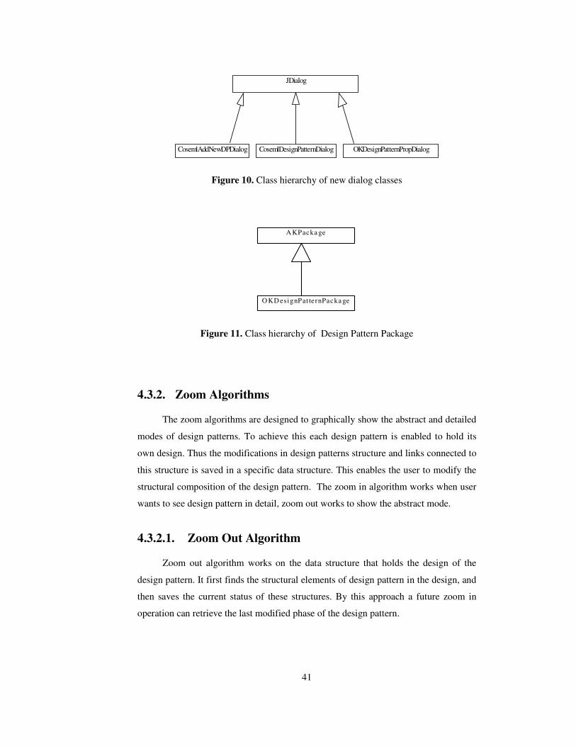
41
JDialog
CosemlAddNewDPDialog CosemlDesignPatternDialog OKDesignPatternPropDialog
Figure 10. Class hierarchy of new dialog classes
A KPacka ge
O KD esignPat ternPacka ge
Figure 11. Class hierarchy of Design Pattern Package
4.3.2. Zoom Algorithms
The zoom algorithms are designed to graphically show the abstract and detailed
modes of design patterns. To achieve this each design pattern is enabled to hold its
own design. Thus the modifications in design patterns structure and links connected to
this structure is saved in a specific data structure. This enables the user to modify the
structural composition of the design pattern. The zoom in algorithm works when user
wants to see design pattern in detail, zoom out works to show the abstract mode.
4.3.2.1. Zoom Out Algorithm
Zoom out algorithm works on the data structure that holds the design of the
design pattern. It first finds the structural elements of design pattern in the design, and
then saves the current status of these structures. By this approach a future zoom in
operation can retrieve the last modified phase of the design pattern.

42
ZoomOut(Input: designPattern; Output: abstract phase of design pattern)
(Shows the abstract phase of design pattern)
begin
Create abstract design pattern
Current = root of design pattern
While design pattern has structural element
Begin
Current = next structural element
If current is node
Begin
While current has connected link
Begin
If link is not connected to the same design pattern
begin
Connect local part to the abstract design pattern
Save connection information
end
end
Read the properties of node and save to the design pattern
End
Else
Read properties of link and save to the design pattern
End
Delete current from the main design
4.3.2.2. Zoom In Algorithm
Zoom in algorithm is the reverse of the zoom out algorithm. Zoom in algorithm
works on the data structure that holds the design of the design pattern. It first reads the
structural elements of the design pattern. Nodes are created in the order of read
operation. At each create operation, external links are updated in the structure that
holds the design pattern. When all the elements are created and updated the old
abstract element for the design pattern is removed from the model.

43
ZoomIn(Input: designPattern; Output: detail of design pattern)
(Shows the detail of design pattern)
begin
Current = root of design pattern
While design pattern has structural element
Begin
Read the next structural element
Current = next structural element
Create a new structural element according to current
Update properties of the new element according to current
If current is node
Begin
While current has connected link
Begin
If link is not connected to the same design pattern
Begin
Remove the connection from the abstract design pattern
Make Connections of link to the new created structure
end
end
End
End
Delete abstract design pattern from the main design

44
CHAPTER 5
CONCLUSIONS AND FUTURE WORK
In this chapter a brief conclusion is presented regarding the use of design
patterns as super components in COSE. Next, the results of a comparison between
COSEML and other popular CASE tools is interpreted. Finally, a section suggesting
the directions for future work is presented.
5.1. Conclusions
The aim of this work is using design patterns in Component Oriented Software
Engineering. To achieve this, a facility for using design patterns is added to the
Component Oriented Software Development tool: COSECASE. Then the use of
design patterns is discussed in details.
The first problem is the representation of a design patterns. A design pattern is
represented as a special kind of package to indicate that it is an abstract structure. It
was initially thought that only abstract level representation of a pattern would be
adequate. After some experiments and observations, it was realized that abstract level
demonstration will not be sufficient because of the detail in the structures and
definitions of design patterns. Design patterns capture a good solution to a recurring
problem in a theoretical and general way. But the practice (design and use of design
patterns) can be different in some cases. Users of design patterns can design it in
different ways according to the requirements and the framework used. Users usually
specialize the generalized solution that design patterns provide while adapting them.
However the concept of ‘generalized solutions’ of design patterns still exists. This
brought the necessity of using design patterns in detailed mode. Therefore a new
symbol and also a new representation are developed such that design patterns can be

45
used both in abstract mode and in detailed mode. User is enabled to make
modifications on a design pattern, defining a design pattern and removing a design
pattern from the system.
After conducting some case studies, it was observed that design patterns could be
used as super components in a component-based design. However this does not mean
that all design patterns can be used as super components directly. To use a design
pattern as a super component in the component-oriented design, this design pattern
must be usable as a component by itself not as a part of a component. Also it must
contain information about how to use; not how to code. It is observed that creational
design patterns can not be used as super components but some structural and
behavioural design patterns can be used as super components in component oriented
development. Creational design patterns can be used in methods of a component but
this is not in the concern area of this research. Structural and behavioural design
patterns that are concerned with the objects can be used as super components.
Incorporating design patterns in COSE has been a valuable experience. The case
studies demonstrated the increased efficiency in reuse. It can be easily felt that bigger
sub-problems are being solved faster in developing system models. The usage of the
pure design pattern definition however had to be extended. The mere abstract
definition of a pattern is a strong idea but our practice shows that in a development
environment, some more concrete definition of a design pattern can be more effective.
Even, implemented variations of a design pattern as its instantiations surfaced as a
valid idea in especially a “built by integration’ avenue to development. If this practice
has a chance to be adopted by the industry, a widely appreciated interpretation of the
concept (design pattern) may settle that suggests more concrete than abstract
utilization of design patterns. Finally, it is observed to be a very effective
enhancement, to provide design pattern incorporations into COSE.
Since design pattern concept is not a specialized concept for component-oriented
development, the usage of design patterns in the other CASE tools and languages are
studied. It is observed that design patterns are widely used in especially object
oriented approach and other software engineering disciplines. This usage has not been
specifically supported by the CASE tools for these approaches.
46
5.2. Future Work
The current version of COSECASE does not support error checking or syntax
enforcement. For now, every symbol can be connected with any other symbol. Such
abilities could be added to develop the application towards a more complete CASE
tool. Design Patterns can be used both in abstraction and detailed mode. But
automatically code generation for components (and also design patterns) is not
available. The need of a component and design pattern catalog is clear. The ability of
searching design patterns from the catalog and using them, and then automatically
generating code could be added to the CASE tool.
Design patterns are used as super components in COSECASE. The mechanism
created for design patterns can be utilized for other widely used designs. The ability to
use abstraction for widely used designs, or some part of a big design can be added to
COSECASE. This may mean selecting a section of an existing design and naming the
selection as a new design pattern.
Inclusion of at least another view and consistency checking among the views
can be done. COSECASE provides, for now, only the structural view using nodes and
connectors. The nodes or alternatively, connectors in a model can be hidden to yield a
single-concern view. Other views, like data or control, can be added. The abstract part
of the model includes data, function and control concepts. Different views only
displaying related abstract components will yield a hierarchically organized data view,
function view and a network of multi-tasking control structures. Connectors are an
important concept in Component Oriented modeling. COSEML includes primitives to
represent them as only graphical links or more detailed specifications of a connection.
Therefore, two different detail level views for “connectors” are possible to implement.
An existing component framework, such as Enterprise JavaBeans (EJB), can be
integrated with COSECASE so that an implementation could be generated, especially
for specific domains. A help facility is also missing. A complete and user-friendly
help option could be added after the completion of the syntax enforcement and error
checking facilities.

47
REFERENCES
[1] A. H. Do�ru, “Component Oriented Software Engineering Modeling Language:
COSEML,” TR-99-3, Computer Engineering Department, Middle East
Technical University, Dec. 1999.
[2] Erich Gamma, Richard Helm, Ralp Johnson, John Vlissides, “Design Patterns,”
Addison & Wesley, 1994.
[3] Floyd Marinescu , “EJB Design Patterns: Advanced Patterns, Processes, and
Idioms,” Jon Wiley & Sons, 2002.
[4] D. Alur, J. Crupi, D. Malks, “Core J2EE Patterns,” Prentice Hall, 2001.
[5] Ed Roman, “Mastering Enterprise Java Beans,” John Wiley & Suns, 2002.
[6] Kara Aydin, “A Graphical Editor For Component Oriented Modeling,”
Engineering Department, Middle East Technical University, Dec. 2001.
[7] Thomas Larsson1, Mikael Sandberg, “Building Flexible Components Based on
Design Patterns,” State of Art, Technical Report, p144 - p152, Mälardalen
University, Department of Computer Engineering, Sweden, 2000
[8] Felix Bachmann, Len Bass, Charles Buhman, Santiago Comella-Dorda, Fred
Long, John Robert, Robert Seacord, Kurt Wallnau, “Volume II: Technical
Concepts of Component-Based Software Engineering, 2nd Edition,” CMU/SEI-
2000-TR-008 ESC-TR-2000-007, May 2000.
[9] R.Schmidt, U. Assmann, “Concepts For Developing Component-based
Systems,” International Workshop on Component-Based Software Engineering,
Forschungszentrum Informatik and Universität Karlsruhe, 1998

48
[10] Ivica Crnkovic, “Concepts For Developing Component-Based Systems,’ John
Wiley & Suns, December 2001.
[11] Wolfgang Pree, “Component Based Software Development: A New Paradigm
in Software Engineering,” Software Concepts and Tools, 18: p169 – p174,
Springer-Verlag, 1997.
[12] Wolfgang Pree, “Essential Framework Design Patterns,” University of
Constance, Germany, 1997.
[13] Alan B., Simon J.,Kelly K., “Using Component Based Development to Built
Web Service Applications,” Rational Software, New York, April 2003.
[14] Frantisek P., Micheal S, “An architectural View of Distributed Objects and
Components,” H. A. Simon, Software Concepts and Tools,66 , 1998.
[15] Kiziltan Z., Jonsson T., Hnich B., “On the Definition of Concepts in
Component Based Software Development,” Department of Information
Science, Uppsala University, July 1997.
[16] M. M. Tanik and E. S. Chan, “Fundamentals of Computing for Software
Engineers,“ Van Nostrand Reinhold, New York, 1991.
[17] E. J. Weyuker, “Testing Component-Based Software: A Cautionary Tale,”
IEEE Software, vol. 15, no. 5, pp. 54-59, Sept./Oct. 1998.
[18] C. Wohlin and P. Runeson, “Certification of Software Components,” IEEE
Trans. Software Eng., vol. 20, no. 6, pp. 494-499, June 1994.
[19] Woodman M., Benediktsson O., Lefever B., Stallinger F., “Issues in CBD
Product Quality and Process Quality,” Computer Science Department,
Middlesex University, London.
[20] Quatrani Terry, “ Visual Modeling With Rational Rose 2000 and UML,”
Addison & Wesley, 1999.

49
APPENDIX A
A BRIEF USER MANUAL FOR USING DESIGN PATTERNS IN COSECASE
A manual for using COSECASE was incorporated in thesis “A Graphical Editor
For Component Oriented Modeling ” by Aydin Kara [6]. Only new added capabilities
are explained here. The new added capabilities are defining and removing design
patterns into and from the system and using them in abstract and detailed mode. These
capabilities are described by figures and examples in the subsequent subsections. The
main window and all other capabilities in COSECASE version 1.0 are kept. Besides,
new buttons for adding/removing design patterns and using design patterns in the main
window are added.
A.1. Design Pattern Dialog
The design pattern dialog box of the improved tool contains four buttons. OK,
Cancel, Add New Pattern and Remove From View As shown in Figure A.1. The
dialog can be activated by using the Design Pattern button in main window. Each
added design pattern is shown to the user through this dialog box. The design pattern
that user wants to use is selected using this dialog box. Add New Pattern button
activates Add New Design Pattern dialog and enables user to add a new design pattern
to the system. Remove From View button removes the selected design pattern from
the system. To remove a design pattern from the system the steps shown in Figure
A.6. should be followed.

50
Figure A.1. Design Pattern Dialog Box
A.1.1. Add New Design Pattern Dialog
Add New Design Pattern Dialog, shown in Figure A.2., is activated when Add
New Pattern button in the Design Pattern dialog is pressed. Dialog contains choose
file, OK and Cancel buttons. Choose File button activates Choose Design Pattern File
Dialog shown in Figure A.3.. This dialog is used to choose the COSEML file that
contains the structure design of the design pattern. User must choose a file and give a
name to the design pattern to add it to the system. In case of the absance of one of
these the tool will generate the corresponding error messages shown in Figure A.4.. To
define a design pattern user must enter a name and choose a file. After this operation if
user presses OK button the new created design pattern will be added to the system and
after this it will be shown in Design Pattern dialog as shown with all steps in Figure
A.5..
Figure A.2. Add New Design Pattern Dialog Box

51
Figure A.3. Choose Design Pattern File Dialog
Figure A.4. Error Dialogs For Add New Design Pattern Dialog
STEP 1. User Enters A Design Pattern Name

52
STEP 2. User Chooses A Coseml File For Design Pattern
STEP 3. User Presses OK Button
STEP 4. System Adds Design Pattern to System For Future Use
Figure A.5. Steps For Adding a Design Pattern to System

53
STEP 1. User Selects the Design Pattern To Remove
STEP 2. User Presses Remove From View Button
Figure A.6. Steps For Removing a Design Pattern from System
A.2. The New Symbols and Usage of Them
To use Design Patterns in COSECASE two new symbols added to the system.
The first one is for Design Patterns. This symbol represents the design pattern in the
detailed mode and it can be only created under a package. This symbol is also added
to the symbol menu found in the bottom of the COSECASE main window. The other
symbol is the Design Pattern Package symbol. This symbol is not added to the symbol
menu because it is generated automatically when needed.

54
A.2.1. Design Pattern Symbol and Its Attributes
Since one of our aim is using design patterns in component system designs,
there must be a unique and standard symbol for design patterns. To achieve this the
design pattern symbol shown in Figure A.7. is used. The similarity of this figure with
other COSEML symbols is clear. This figure represents the abstract mode of the
design patterns. It has four options as shown in Figure A.8.. These options are delete,
Properties, Open Specification and Zoom In. Delete operation deletes the design
pattern from the model. The properties attributes enables the properties dialog. Open
Specification shows user the detail of the design pattern in an another COSEML
window. Zoom In is used to use the detail of the design pattern instead of the abstract
mode.
Figure A.7. The COSEML Figure Represents Abstract Mode of a Design Pattern
Figure A.8. Attributes of a Design Pattern
A.2.1.1. Design Pattern Properties Dialog
Design Pattern properties dialog shown in Figure A.9. is activated when the
“properties” item on the submenu is pressed. It has two attributes “Design Pattern
Name” and Text Area. Design Pattern Name is used to give a specific name to the
Design Pattern in the model. The text area is used to enter the important and necessary
expressions.

55
Figure A.9. Design Pattern Properties Dialog
A.2.2. Design Pattern Package Symbol and Its Attributes
The Design Pattern Package Symbol is shown in Figure A.10. It is similar to a
regular package symbol but differs in some ways. It is not used by the user directly. It
is generated when a design pattern’s zoom in function is activated. Users are enabled
to use design patterns in both abstract and detailed modes. In abstract level, a design
pattern is represented by the design pattern symbol. But in detail use of design
patterns the need to distinguish the design pattern structure and other structures in the
model has occurred. To achieve this distinction, the Design Pattern Package Symbol is
created. This symbol has all the properties that a regular package has. All the design
patterns structure are created under this package and the user can clearly see which
part of the design originates from design patterns. Since one of our aim is to use
design patterns both in abstract and detailed mode there must be a way to return from
detailed modes to abstract mode. This special package handles this issue. The zoom
out option shown in Figure A.11. realize this requirement. When zoom out property is
activated the design pattern package and other structures that are created under this
package are all removed and the abstraction is created again. The “zoom in” and
“zoom out “ capabilities enable the user to switch between the abstract and detailed
modes of a design pattern at any time during development. Other capabilities of design

56
pattern package are “delete” and “properties”. These are derived from the normal
package defined in COSECASE v1.0 and they are the same.
Figure A.10. COSEML Figure Represents Design Pattern Package (when design
pattern is used in detailed mode)
Figure A.11. Action options on a Design Pattern Package

57
APPENDIX B
CONSTRUCTION STEPS OF A SAMPLE MODEL
A COSEML model for the beginning of the J2EE framework development is
shown in Figure 8. To construct the model, the user starts with creating design patterns
which will be used. First front controller design pattern is created and defined as the
framework to the system. Front Controller is a design pattern which is used to abstract
a generic servlet mechanism which is responsible for taking requests from clients and
sending these request to the server side by parameters. Therefore it has two functions :
Give respond and take request.
Building the J2EE framework model continuous in a similar fashion: new
design patterns are included and then their details are modified. The enhancement
includes forming of connectors also.
Figure B.1. Detail of Front Controller Design Pattern

58
Figure B.2. Add New Design Pattern for Front Controller Design Pattern
Figure B.3. Defining Name and Path for Design Pattern
Figure B.4. Existing Design Patterns List After Front Controller Design Pattern is
Added
By the same approach all other design patterns are created and defined to the
system. Command design pattern is responsible for taking the request from client side
and then decides the external system that must be interacted and sends the request to
this external system. There is a file which holds the commands, the external system
and operation which will run on this external system. Since it is responsible for taking
request from client, front controller design pattern is used in command design pattern.
The following figures illustrate the introduction of new patterns and then, their
modification in the effort to build the J2EE framework.

59
Figure B.5. Detail of the Command Design Pattern
Figure B.6. Command Pattern After Front Controller Design Pattern is Created
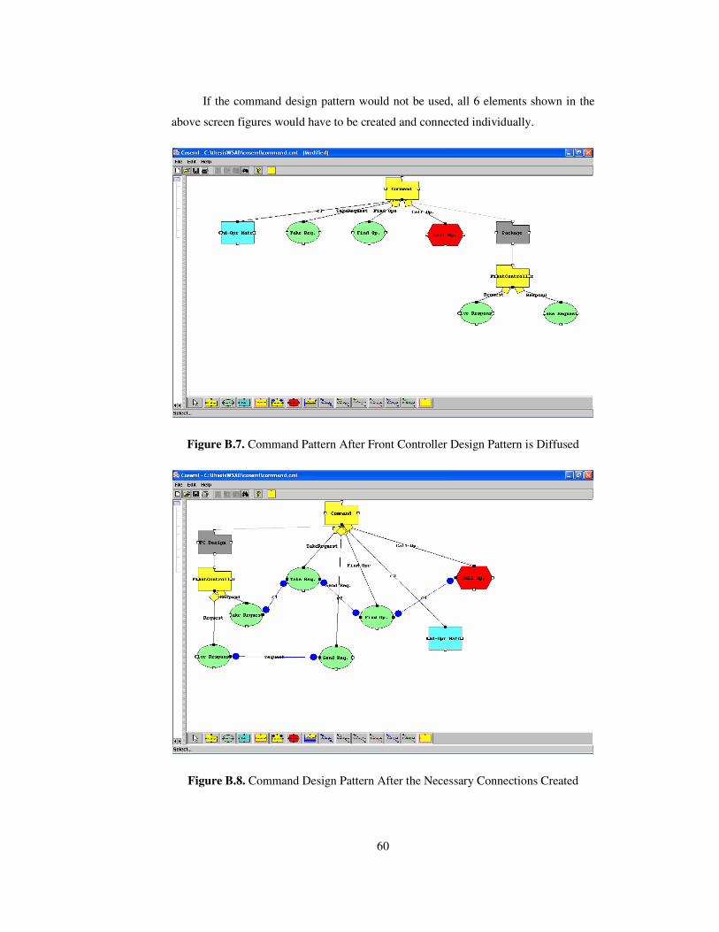
60
If the command design pattern would not be used, all 6 elements shown in the
above screen figures would have to be created and connected individually.
Figure B.7. Command Pattern After Front Controller Design Pattern is Diffused
Figure B.8. Command Design Pattern After the Necessary Connections Created

61
The wrapper design pattern is the pattern that is the first leg for database
operations in the framework. This design pattern is an EJB design pattern that decides
which session base class or classes will be activated and in which order these will be
activated. Since there is a decide activity by using a file, command design pattern is
used in the design phase of wrapper design pattern.
Figure B.9. Existing Design Patterns List After Command Design Pattern is Added
Figure B.10. Wrapper Design Pattern After Command Design Pattern is Created

62
Figure B.11. Wrapper Pattern After Call Sessions Sequentially Function is Created
Figure B.12. Wrapper Pattern Before Command Pattern is Diffused

63
Figure B.13. Wrapper Pattern After Command Pattern is Diffused
Session Base design patterns use session beans or in other words session beans
inherit session base design patterns. Session base design patterns handles all the
responsibilities for transaction and rollback operation. It also decides how to connect
to database, by using entity beans or Data Access Object Design patterns. Since again
there exist a decide activity by using a file, command design pattern is again used in
the design phase of session base design pattern.
Figure B.14. Session Base Pattern After Command Design Pattern is Created

64
Figure B.15. Session Base Pattern After Prepare Transactions Function is Created
Figure B.16. Session Base Pattern After Rollback Function is Created

65
Figure B.17. Session Base Pattern Before Command Design Pattern is Diffused
Figure B.18. Session Base Pattern After Command Design Pattern is Diffused

66
The data access object design pattern handles all the JDBC (Java Database
Connection) requirements such as providing a connection and resources from the pool,
removing connections and handling exceptions. The queries that will run is decided by
the DAO using the command. A file is used to hold the relation between the command
and queries.
Figure B.19. Detail of Data Access Design Pattern
Since the necessary design patterns are defined to the system, framework design
can be done easily. First a package is inserted which describes the framework. And
then a package is inserted which describes the client operations and classes. Since
command design pattern will be used to make operations between the client and server
sides, this design pattern is added to the framework. The necessary relations to use
command design pattern are introduced in the detail mode of the super component.
External systems are defined by creating packages and necessary links are created to
these packages.

67
Figure B.20. Design of Example After Client Package Created
Figure B.21. Design of Example After Command Pattern Created

68
Figure B.22. Design of Example Before Command Pattern Diffused
Figure B.23. Design of Example Before Command Pattern Diffused

69
Figure B.24. Design of Example After Connections with External Systems Done
After external systems are created, the wrapper design pattern is added to the
framework in case us database operations will be used. After the wrapper design
pattern is added, the session base design pattern and data access object design pattern
are added. Finally a package that represents the database is created.
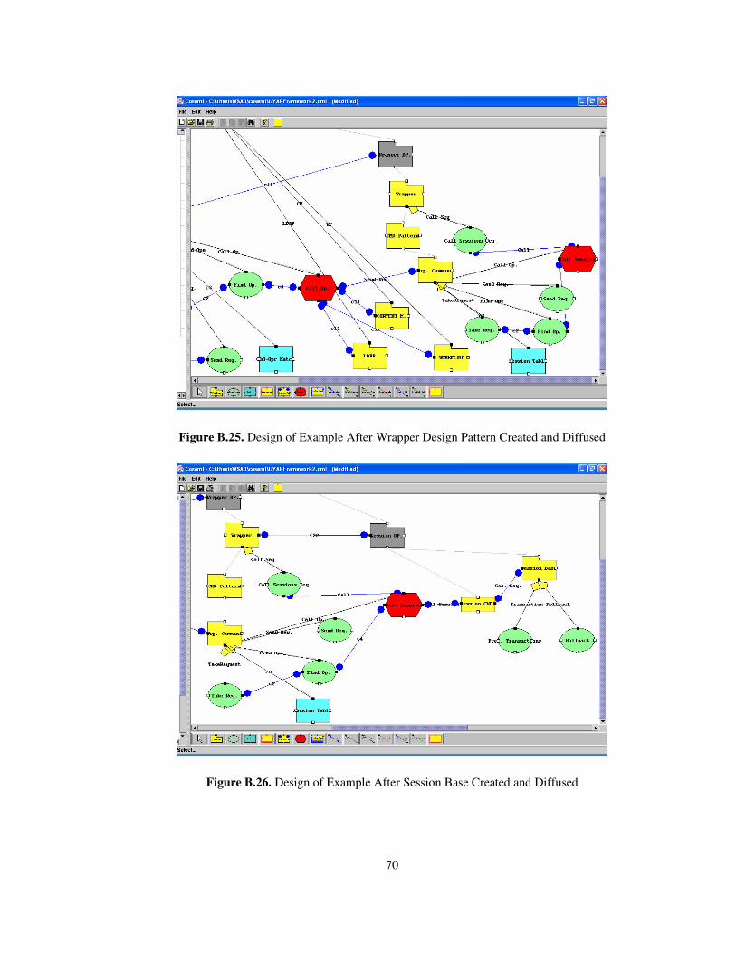
70
Figure B.25. Design of Example After Wrapper Design Pattern Created and Diffused
Figure B.26. Design of Example After Session Base Created and Diffused

71
Figure B.27. Design of Example After Data Access Pattern Created and Diffused
Figure B.28. Design of Example After All Connections Created

72
If the capability of using design patterns was not added to the COSECASE, then these
detailed designs of design patterns had to be created at each use. The final design
would be the same except for the packages that represent the design pattern’s detailed
design. These design patterns are modified in some way to make them appropriate and
specific to this design. For example the original design of the command design pattern
does not have an extra file to find the appropriate external system or wrapper
component. For each operation a new class inherited from the base command class
would be implemented. But in this design instead of all of these classes, a generic
class that conducts the same operation by using a file and a parameter set. Therefore
the original detailed design of the command design pattern is modified. The same
approach is repeated for the data access object design pattern. Instead of implementing
a different class that is inherited from data access design pattern, a hash map file that
contains the queries and relations of these queries with commands and parameters of
these commands is used. Data access design pattern is modified to achieve these
modifications.
Related Documents