Chapter 1 Introduction A water cooler is a device that cools and supplies water for drinking purposes. They are extensively used for home as well as commercial applications. For home applications, they are more commonly referred to as water dispensers, which along with cooling water also purify it. The cooling capacities range from around 3 L/h to 5 L/h and they consume 100 W to 200 W power for a family of five to six people. In the latest models, water heating systems are also being coupled with water coolers to enhance their productivity. For commercial applications the cooling capacities could range from 40 L/h for small establishments to 200 L/h for large commercial establishments like hospitals, malls, railway stations, hostels and educational institutions. (a) (b) Photo 1. (a) An USHA 3 L/h water dispenser for home applications (b) A 200 L/h large USHA water cooler for commercial usage Most of today’s water coolers work on vapour compression cycle. R134a is widely used as the refrigerant due to its low boiling point (-23 o C) and very low ozone layer depletion potential. The major components of vapour compression cycle are the compressor, condenser, expansion valve

Report.pdf
Dec 24, 2015
Refrigeration report
Welcome message from author
This document is posted to help you gain knowledge. Please leave a comment to let me know what you think about it! Share it to your friends and learn new things together.
Transcript

Chapter 1
Introduction
A water cooler is a device that cools and supplies water for drinking purposes. They are extensively
used for home as well as commercial applications. For home applications, they are more
commonly referred to as water dispensers, which along with cooling water also purify it. The
cooling capacities range from around 3 L/h to 5 L/h and they consume 100 W to 200 W power for
a family of five to six people. In the latest models, water heating systems are also being coupled
with water coolers to enhance their productivity. For commercial applications the cooling
capacities could range from 40 L/h for small establishments to 200 L/h for large commercial
establishments like hospitals, malls, railway stations, hostels and educational institutions.
(a) (b)
Photo 1. (a) An USHA 3 L/h water dispenser for home applications (b) A 200 L/h large USHA
water cooler for commercial usage
Most of today’s water coolers work on vapour compression cycle. R134a is widely used as the
refrigerant due to its low boiling point (-23oC) and very low ozone layer depletion potential. The
major components of vapour compression cycle are the compressor, condenser, expansion valve

and the evaporator. The diagrammatic representation of a typical single stage vapour compression
cycle is shown in Figure 1.
(a)
(b)
Figure 1. (a) A typical vapour absorption refrigeration cycle (b) Temperature-entropy diagram
of the vapour absorption refrigeration cycle

The temperature-enthalpy diagram of the cycle is shown in Figure 2. The circulating refrigerant
vapour enters the compressor at point 1 (shown in figure 3). In the compressor, the vapour is
compressed at nearly constant entropy and exits it at a higher temperature but still below vapour
pressure at point 2. From point 2 to 3, the vapour cools to the vapour pressure and then enters the
condenser, where it condenses to form liquid refrigerant. Between points 4 and 5, the vapour passes
through the expansion valve, its pressure decreases abruptly at a constant enthalpy. The resultant
liquid-vapour refrigerant enters the evaporator, where it boils by absorbing heat from water,
thereby cooling it.

Chapter 2
Compressors
A refrigeration compressor is a machine used to continuously draw the refrigerant vapour from the
evaporator, so that a low pressure and low temperature can be maintained in the evaporator at
which the refrigerant can boil by extracting heat from the refrigerated space. The compressor then
has to raise the pressure of the refrigerant to a level at which condensation can occur by rejecting
heat to the cooling medium in the condenser. It also continually circulates the refrigerant through
the refrigerating system. The compressor is driven by some prime mover.
2.1 Classification of Compressors
Compressors can be of various different types, based on the fluid flow, the method of compression,
the number of working strokes, the number of stages, the method of drive employed and the
location of prime mover.
2.2.1 Based on the fluid flow
1. Positive displacement compressors
In positive displacement compressors, the fluid flow is intermittent. These compressors
ensure positive admission and delivery of fluid preventing undesired reversal of flow
within the machine.
2. Rotodynamic compressors
In rotodynamic compressors, the flow is continuous. The fluid is subject to flow processes
and the work is transferred by virtue of the change of momentum of stream of fluid flowing
at a high speed over blades or vanes attached to a rotor.
2.2.2 Based on the method of compression
1. Reciprocating compressors

The compressors in which the vapour refrigerant is compressed by the back and forth
motion of the piston are called reciprocating compressors.
2. Rotary compressors
The compressors in which the vapour refrigerant is compressed due to the movement of
blades are called rotary compressors.
3. Centrifugal compressors
The compressors in which rise of pressure of vapour refrigerant is done by a centrifugal
force are called centrifugal compressors.
2.2.3 Based on the number of stages
1. Single-stage compressors
In a single-stage compressors, the vapour refrigerant is compressed in a single cylinder
and then delivered at high pressures. These compressors need a crankshaft seal to prevent
the leakage of refrigerant.
2. Multi-stage compressors
In multi-stage compressors, vapour refrigerant is delivered at high pressures using two or
more cylinders placed in series. In these compressors, use of crankshaft seal is eliminated.
They are used for small capacity refrigeration systems like domestic refrigerators and home
freezers.
2.2.4 Based on the location of prime mover
1. Semi-hermetic compressors
In semi-hermetic compressors, the direct drive, motor and the compressor are all placed
in separate housings.
2. Hermetic compressors

In hermetic compressors, the direct drive, motor and compressor are all placed in the same
housing.
2.2 Reciprocating Compressors
The compressors in which vapour refrigerant is compressed by the reciprocating motion of the
piston are called reciprocating compressors. This compressors are used for refrigerants which have
comparatively low specific volume and large differential pressure such as R17, R12, R22 and R40.
Reciprocating compressors are available in sizes as small as 1/12 KW which are used in domestic
refrigerators and up to about 150 KW for large capacity installations. Two types of reciprocating
compressors in general use are single acting vertical compressor and double acting horizontal
compressor. Single acting compressors have their cylinders arranged vertically, radially or in a V
or W form. Double acting compressors usually have their cylinders arranged horizontally.
Figure 2. Sectional view of a reciprocating compressor
Reciprocating compressors can be of two different types:
Single acting reciprocating compressors
The reciprocating compressors are the compressors in which the compression is
accomplished using only side of the piston.
Double acting reciprocating compressors

The compressors using both sides of the piston during compression are known as double
acting reciprocating compressors.
2.3 Rotary Compressors
Rotary compressors are positive displacement machines in which compression of the fluid is
affected directly by a rotor. Since the clearance in rotary compressors is negligible, therefore they
have high volumetric efficiency. These compressors may be used with refrigerants R-12, R-22, R-
114 and R-17. Rotary compressors can be of three basic types:
Rotating blade type rotary compressors
The rotating blade type rotary compressors consist of a cylinder and a slotted rotor
containing a number of blades. The centre of the rotor is eccentric with the centre of the
cylinder. The blades are forced against the cylinder wall by centrifugal action during the
rotation of the rotor.
Figure 3. Rotating blade type rotary compressor
Screw compressors
Rotary screw compressors consist of two helically grooved rotors which rotate in a
housing. The male rotor consists of lobes and is normally the driving motor. The female
rotor has gullies and is normally the driven rotor. A four lobe male rotor will drive a six
gully female rotor at two third of its speed. As they are high speed rotary machines, a large

volume can be handled by them therefore they are found extremely suitably for large
capacity, low-temperature applications like central air conditioning plants.
Figure 4. Screw compressor
Scroll compressors
Scroll compressors are valve-less positive displacement machines like rotary and screw
compressors. Because of their simplicity, they have become very popular with the industry
in recent years. Here the compression is achieved by two intermitting, spiral shaped scroll
members, one of which is a fixed screw and the other one is an orbiting scroll. The capacity
ranges from 1 to 14 TR.
Figure 5. Scroll compressor

2.4 Centrifugal Compressors
Centrifugal compressors increase the pressure of low pressure vapour refrigerant to high pressure
by centrifugal force. The centrifugal compressor is generally used for refrigerants that require large
displacement and condensing pressure such as R11, R113. A simple centrifugal compressor
consists of an impeller to which a number of curved vanes are fitted symmetrically. The impeller
rotates in an airtight volute casing with inlet and outlet points.
Figure 6. Centrifugal compressor
2.5 Selection
The compressor chosen for the desired application, i.e. a medium capacity water cooler is a single-
acting, reciprocating type, single-stage, hermetic sealed compressor.
The hermetic, reciprocating type compressor has been chosen for the desired application because
it offers several advantages as compared to its other counterparts. These are as follows:
Hermetic sealed compressors prevent the leakage of refrigerant.
Hermetic compressors require small space because of their compactness.
The lubrication of hermetic compressors is simple as the motor and compressor operates
in a sealed space with the lubricating oil.
Hermetic compressors are less noisy.

Reciprocating compressors are available in sizes as small as 1/12 KW which are used in
small domestic refrigerators and up to about 150KW.
Centrifugal compressors are not practical below 50TR capacity.
Manufacturing cost is high for centrifugal compressors.
Power requirement is lower for reciprocating compressors as compared to centrifugal
compressors.
The cost of a typical rotary screw compressor, in terms of initial purchase price and
installation, is generally less than a reciprocating compressor. However, provided that it is
properly maintained, a reciprocating compressor can be expected to last between two and
five times longer.

Chapter 3
Condensers
Condenser is a heat exchanger which removes heat of the hot refrigerant discharged from the
compressor, thus condensing the vapour refrigerant in the process. Condensation is the change of
the physical state of matter from gas phase into liquid phase. Condensation processes can be
classified into two types:
Film wise condensation
Drop wise condensation
Compared to film-wise condensation, drop-wise condensation has a greater surface heat-transfer
coefficient as it has a greater area exposed to the saturation vapour. Hence the design of the
condenser changes with the type of condensation phenomenon occurring too.
The hot vapour refrigerant which is condensed consists of the heat absorbed by the evaporator and
the heat of compression added by the mechanical energy of the compressor motor. The heat from
the hot vapour refrigerant is removed first by transferring it to the walls of the condenser tubes and
then from the tubes to the condensing medium, which may be air or water or a combination of
both.
3.1 Stages in Condensation
Condensation in a condenser occurs in three stages:
De-superheating of the hot gas.
Condensing of the gas to liquid state and release of the latent heat.
Sub-cooling of the liquid refrigerant.
Since the phase in each stage is different, the design of each stage must be taken separately.
Generally sub-cooling part in the condensers is very less and is neglected. But in systems with
very high sub-cooling, sub-cooling cannot be neglected.

Figure. Temperature profile during condensation
3.2 Classification of Condensers
Condensers are classified on the basis of type of cooling method employed. Application wise
condensers are widely used in HVAC-R industry and hence further discussion on condensers is
carried out in the context of HVAC-R industry. Hence condensers are classified into air cooled,
water cooled, and evaporative condensers.
3.2.1 Water cooled condenser
In a water cooled condenser, the heat rejected in all of the stages of the condensation is received
as sensible heat by the water which is acting as coolant. Water cooled condensers require regular
maintenance due to scaling. Due to large heat transfer coefficient of water the area required for
heat transfer is less. Hence where there is no scarcity of water and space is a constraint, water
cooled condensers are preferred. A water cooled condenser can be shell and coil condenser, tube
in tube condenser, or shell and tube condenser.
3.2.1.1 Shell and coil condenser
This type of condenser is used for medium capacity refrigeration. It is a variant or rather simpler
version of shell and tube condenser. The tubes are replaced by a spiral coil. The coil is inserted in

the shell and according to the capacity requirement, the refrigerant can flow inside or outside the
coil. Finned coils can also be used to increase the rate of heat transfer.
Figure. A shell and coil condenser
3.2.1.2 Tube in tube/Double tube condenser
This type of condenser is used for low capacity refrigeration up to 10 TR. The refrigerant flows in
the annulus. Long tubes cannot be used as it increases the pressure drop on the refrigerant side.
Hence long tubes are not suitable for large capacity condensers.
Figure. A tube in tube condenser
3.2.1.3 Shell and tube condenser
This is the most common type of condenser used in systems from 2 TR up to thousands of TR
capacity. In these condensers the refrigerant flows through the shell while water flows through the

tubes in single to four passes. The condensed refrigerant collects at the bottom of the shell. The
coldest water contacts the liquid refrigerant so that some sub cooling can also be obtained.
Figure. A schematic of a shell and tube type condenser
3.2.2 Air cooled condenser
In an air cooled condenser the secondary fluid is air. Due to lesser heat transfer coefficient as
compared to water, a larger heat transfer area is required. Air cooled condenser is widely used in
commercial refrigeration system with low to medium capacity. An air cooled condenser can be of
natural convection type or forced convection type.
3.2.2.1 Natural convection type
Natural convection type condensers are used for small capacity units like household refrigerators
and freezers. No power is required to run these type of condensers. The heat transfer coefficient in
this type is very less when compared to forced type. Hence a large heat transfer area and thereby
a larger length of the condenser is required.

Figure. A natural convection type condenser
3.2.2.2 Forced convection type
In a forced convection type condenser, the circulation of air over the condenser surface is
maintained by using a fan or a blower. These condensers normally use fins on air-side for good
heat transfer. Forced convection type condensers are commonly used in window air conditioners,
water coolers and packaged air conditioning plants. An evaporative condenser uses the evaporation
of water spray to remove the latent heat of condensation of the refrigerant during condensation. It
is actually a simplified combination of a water cooled condenser and cooling tower.
Figure. A forced convection type condenser

3.2.3 Evaporative condenser
Evaporative condensers are used in medium to large capacity systems. These are normally cheaper
compared to water cooled condensers, which require a separate cooling tower. Evaporative
condensers are used in places where water is scarce. Water is used in a closed loop in this type of
condenser. Since condenser has to be kept outside, this type of condenser requires a longer length
of refrigerant tubing, which calls for larger refrigerant inventory and higher pressure drops.
Figure. A diagram of evaporative condenser
3.3 Selection
For the required application, design of both water cooled and air cooled condensers will be carried
out. Among air-cooled condensers, the forced convection type condenser is selected because the
natural convection type has larger space requirements. Among the water-cooled condensers, the
shell and coil type condenser is selected for design because shell and tube type requires frequent
maintenance due to high fouling rate, whereas tube and tube type requires a very large length,
which increases the pressure losses beyond the permissible limits, which is undesirable.
Chapter 4
Evaporators
An evaporator is a heat exchanger in which refrigerant is evaporated, thereby cooling a fluid (here
water) circulating through the evaporator. The latent heat absorbed by the refrigerant cools the
water around it.
4.1 Boiling in Evaporators
Boiling is a liquid-to-vapour phase change just like evaporation, but there are significant
differences between the two. Evaporation occurs at the liquid-vapour interface when the pressure
is less than the saturation pressure of the liquid at the given temperature. Boiling, on the other
hand, occurs at the solid-liquid interface when the liquid is brought into contact with a surface
maintained at a temperature Ts sufficiently above the saturation temperature of the Tsat of the liquid.
Boiling is classified as pool boiling or flow boiling, depending on the presence bulk fluid motion.
4.1.1 Pool boiling
In pool boiling, the fluid is not forced to flow by a mover such as a pump, and any motion of the
fluid is due to natural convection currents and the motion of bubbles under the influence of
buoyancy.
Boiling regimes and boiling curve
During boiling four different regimes are observed: natural convection boiling, nucleate boiling,
transition boiling and film boiling.
1. Natural Convection Boiling (up to point A): During this stage the liquid is slightly
superheated and evaporates as it rises to the free surface. The motion of the fluid in this
case is purely due to natural convection currents.

2. Nucleate Boiling (between points A and C): The first bubbles start forming at A of the
boiling curve at various preferential sites of the heating surface. Point A is called onset of
nucleate boiling.
3. Transition boiling (between points C and D): As the heater temperature is increased beyond
C, the heat flux decreases. In transition boiling, both nucleate as well as film boiling occur.
4. Film boiling (beyond point D): In this region the heat transfer is completely covered by a
continuous vapour film. The heat transfer coefficients are low in this regime.
Figure 4.1. Various regimes obtained during boiling
4.1.1 Flow Boiling
In flow boiling, the fluid is forced to move by an external source such as a pump as it undergoes a
phase change process. The boiling in this case exhibits the combined effects of convection and
pool boiling. The flow boiling can also be classified as either external flow boiling or internal flow
boiling.
External flow boiling over a plate or cylinder is similar to pool boiling, but the added
motion increases both the nucleate boiling heat flux and the critical heat flux considerably.

Internal flow boiling is much more complicated in nature because there is no free surface
for the vapour to escape, and thus both the liquid and the vapour are forced to flow together.
The two-phase flow in a tube exhibits different flow boiling regimes, depending on the
relative amounts of the liquid and the vapour phases. This complicates the analysis even
further.
4.2 Classification
Evaporators are primarily classified on the basis of the type of construction, on the basis of
refrigerant circulation and the mode of heat transfer. This classification is further discussed in the
following sections.
4.2.1 Based on the type of construction
Bare-Tube-Coil Evaporators
They were one of the first types of evaporators used. They consist of long run of coils,
through which the refrigerant flows. They are simple in construction and hence can be
easily fabricated and cleaned. However, they provide a very little contact area and hence
the length of the tube has to be very long even for low capacity refrigeration systems. They
are usually constructed of either steel pipe or copper tubing. Steel pipes are used for large
evaporators while copper tubing is for smaller evaporators. Common shapes are flat, oval
trombone and spiral.
(a) (b)
Figure 1. Common designs of bare tube evaporators. (a) Flat zigzag coil (b) Oval trombone

Finned-Tube Evaporator
These consist of bare tubes or coils over which metal plates or fins are fastened. The fins,
serving as secondary heat absorbing surfaces, have the effect of increasing the overall
surface are of the evaporator, thereby improving its efficiency. The metal fins are
constructed of thin sheets of metal having good thermal conductivity. Fin spacing is kept
large for larger tubes and small for smaller tubes. Formation of frost drastically reduces
their performance, as the frost restricts the passage of fluid between the fins. Hence, they
should never be used for refrigeration temperatures below 0oC. They are primarily
designed for air-conditioning applications.
Figure 2. Actual Finned Tube Evaporator
Plate-Surface Evaporator
These evaporators consist of formed tubing installed between two metal plates, which are
welded together at edges. In order to provide good thermal contact between the welded
plates and the tubing carrying is evacuated so that the pressure of the atmosphere exerted
on the outside surface of plates, holds the plates firmly against the tubing inside. These are
widely used as partitions in freezers, frozen food display cases, ice-cream cabinets, etc.
They are helpful when unusual peak load conditions are experienced frequently.

Figure 3. Standard Serpentine Plate Evaporator
Shell-and-Tube Evaporator
The shell-and-tube evaporators are very efficient, require minimum floor space and head
space. They are easy to maintain, and hence are widely used in medium to large capacity
refrigeration systems. They consist of a shell and a large number of tubes arranged parallel
to each other. The shell diameters range from 150 mm to 1.5 m. The number of tubes may
vary from fifty to several thousand, each of length 1.5 m to 6 m. A series of baffles channels
the fluid throughout the shell side. The baffles create cross flow through the tube bundle
and increase the velocity of fluid, thereby increasing its heat transfer coefficient. The
velocity of fluid flowing perpendicular to the tubes should be at least 0.6 m/s to clean the
tubes and less than the velocity limit of the tube and baffle materials, to prevent erosion.
Figure 5. An actual shell and tube type evaporator

Shell-and-Coil Evaporator
These evaporators consist of a tank in which the fluid to be cooled is placed. A simple
coiled tube is used for cooling the fluid. The fluid in shell gives large amount of thermal
storage capacity and hence has can give good performance with small but infrequent peak
loads. Sometimes, the refrigerant is placed inside the shell and the fluid to be cooled flows
through the tube. These types of shell-and-coil evaporators can give instantaneous cooling.
They are mostly used at low capacities, e.g., for bakeries, photographic labs and to cool
drinking water.
Figure 7. A shell and coil type evaporator
Baudelot Evaporator
These evaporators are used to cool the fluid to near its freezing temperature. The fluid
circulates over the outside of vertical plates, which are easy to clean. The inside surface
of the plates is cooled by evaporating the refrigerant. The fluid to be cooled flows
uniformly from the top of the evaporator to the bottom. Insulation is usually provided to
prevent heat loss. They are mainly used for industrial applications and especially in dairy
industry.

Figure 8. A Baudelot evaporator
4.2.2 Based on refrigerant circulation
Direct-Expansion Evaporator
The refrigerant evaporates inside the tubes of this evaporator. They are usually used with
positive displacement compressors like reciprocating compressors, rotary screw
compressors etc. The distribution of refrigerant is critical in these types of evaporators, as
any imbalance causes a drastic decrease in heat transfer coefficient. The number of passes
can be single or multiple. They are generally used for low to medium capacity refrigeration
applications.
Figure. Direct-Expansion shell and tube type evaporator

Flooded Evaporator
The flooded type of evaporator is always completely filled with the refrigerant. The
evaporated vapour is taken away by the compressor. The inside surface of these
evaporators is always completely wetted with liquids and hence they have very high heat
transfer coefficient. However, they are bulky and require a large amount of refrigerant
charge. One variation of flooded shell-and-tube evaporator is spray shell-and-tube
evaporator. When the refrigerant pressure has an adverse effect on heat transfer coefficient,
the liquid is sprayed in the tubes, rather than flooding them.
Figure. Flooded shell and tube type evaporator
4.2.3 Based on the mode of heat transfer
Forced convection evaporators
A fan or a pump is used to circulate the fluid being refrigerated. As the fluid moves at a
high velocity over the heat transfer surface, the heat transfer coefficient is quite high.
However they cost more and are bulkier.
Natural convection evaporators
The fluid being refrigerated flows by natural convective currents set due to density
difference that arises due to variation in temperature. They are generally used for home and
medium applications, as the heat transfer coefficient is less, but they are cheaper and less
bulky.
4.3 Selection
For the required application, which is a medium capacity water cooler, shell and coil type
evaporator is chosen. The reasons which dictate the choice of shell and coil type evaporator are:
Since only one coil of larger diameter is used, the construction is easier. The single coiled
tube has only to be soldered inside the shell at opening and exit.
The coiled tubing is free to expand and contract with temperature changes because of its
spring action.
The coil can withstand strain caused by temperature changes.
It is suitable for small capacity liquid cooling of around 2-10 TR.
Shell and coil type evaporator is specifically used in applications where cleanliness is
required, e.g. bakeries, photographic laboratories, drinking water, etc. Since the application
involves drinking water which should not be contaminated while being refrigerated, this
type is thus chosen.

Chapter 5
Expansion Devices
Expansion devices are the devices which are used to lower the pressure of the refrigerant from the
high value at the compressor, condenser side to the low value at the evaporator side. There are
basically two functions of expansion devices:
To reduce the pressure from the condenser pressure to evaporator pressure.
To regulate the refrigerant flow rate from the high pressure liquid line into the evaporator
at a rate equal to the evaporation rate in the evaporator.
In cases where constant evaporator temperature is to be maintained, or where it is desired that no
liquid refrigerant should enter the compressor, the mass flow rate has to be controlled in a manner
that only superheated vapour exits the evaporator. It is therefore, required that this control be done
in such a way that minimum energy is used, while meeting the criteria of temperature and cooling
load.
5.1 Classification
The expansion devices which are employed in refrigeration systems can be divided into two broad
categories:
Fixed opening type, in which the flow area remains fixed. These include capillary tubes.
Variable opening type, in which the flow area changes with the changing mass flow rates.
These include Constant Pressure Automatic Expansion Valves, Thermostatic Expansion
Valves and Float type Expansion Valves.
5.1.1 Capillary Tube
Capillary tube is one of the most widely used throttling devices in the refrigeration systems. The
capillary tube is a long copper tube of very small internal diameter coiled to several turns so that
it would occupy less space. The internal diameter varies from 0.5 to 2.28 mm. Capillary tube used
as the throttling device in the domestic refrigerators, deep freezers, water coolers and air
conditioners.
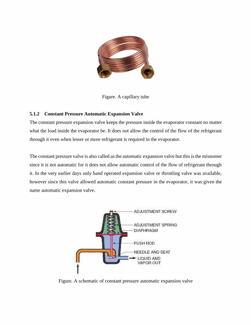
Figure. A capillary tube
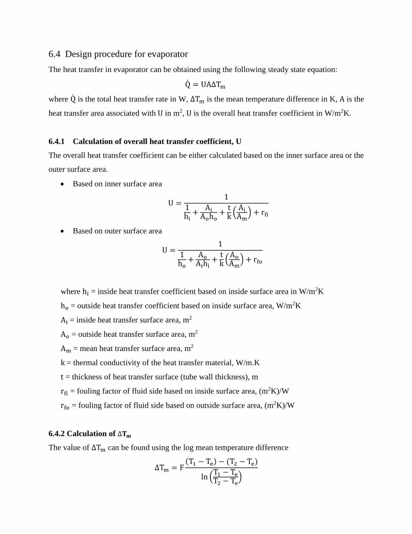
5.1.2 Constant Pressure Automatic Expansion Valve
The constant pressure expansion valve keeps the pressure inside the evaporator constant no matter
what the load inside the evaporator be. It does not allow the control of the flow of the refrigerant
through it even when lesser or more refrigerant is required in the evaporator.
The constant pressure valve is also called as the automatic expansion valve but this is the misnomer
since it is not automatic for it does not allow automatic control of the flow of refrigerant through
it. In the very earlier days only hand operated expansion valve or throttling valve was available,
however since this valve allowed automatic constant pressure in the evaporator, it was given the
name automatic expansion valve.
Figure. A schematic of constant pressure automatic expansion valve

5.1.3 Thermostatic Expansion Valve
The thermostatic expansion valve is the automatic valve that maintains proper flow of the
refrigerant in the evaporator as per the load inside the evaporator. If the load inside the evaporator
is higher it allows the increase in flow of the refrigerant and when the load reduces it allows the
reduction in the flow of the refrigerant. This leads to highly efficient working of the compressor
and the whole refrigeration and the air conditioning plant. The thermostatic expansion valve also
prevents the flooding of the refrigerant to the compressor ensuring that the plant would run safely
without any risk of breakage of the compressor due to compression of the liquid.
Figure. A thermostatic expansion valve
5.1.4 Float Valve
Float type expansion valves are normally used with flooded evaporators in large capacity
refrigeration systems. A float type valve opens or closes depending upon the liquid level as sensed
by a buoyant member, called as float. The float could take the form of a hollow metal or plastic
ball, a hollow cylinder or a pan. Thus the float valve always maintains a constant liquid level in a
chamber called as float chamber. Depending upon the location of the float chamber, a float type
expansion valve can be either a low-side float valve or a high-side float valve.

Figure. A sectional view of a Float Valve
5.1.4.1 Low Side Float Valve
A low-side float valve maintains a constant liquid level in a flooded evaporator or a float chamber
attached to the evaporator. When the load on the system increases, more amount of refrigerant
evaporates from the evaporator. As a result, the refrigerant liquid level in the evaporator or the
low-side float chamber drops momentarily.
5.1.4.2 High Side Float Valve
A high-side float valve maintains the liquid level constant in a float chamber that is connected to
the condenser on the high pressure side. When the load increases, more amount of refrigerant
evaporates and condenses. As a result, the liquid level in the float chamber rises momentarily.
5.2 Selection
For the medium capacity water cooler application, expansion valve selection is based on the type
of evaporator employed. A table showing different types of evaporators for various capacity ranges
and the expansion valves employed for the corresponding evaporator types. It can be seen that for
the required application, since power requirement is less than 10 kW, a shell and coil type
evaporator in conjunction with a thermostatic expansion valve is used.

A thermostatic expansion valve provides several advantages which make its use suitable. Some of
them are listed as follows:
It maintains the flow of the refrigerant to the evaporator as per the load inside. Thus the
refrigeration or the air conditioning plant can run to the optimum capacity as per the
requirements.
It keeps the evaporator fully active and helps getting the optimum cooling effect from it.
Since the entire refrigerant in the evaporator gets vaporized the chances of the liquid
refrigerant particles going to the compressor are reduced. This reduces the chances of the
breakdown of the compressor due to compression of the liquid.
Table. Summary of characteristics of various types of evaporators for different power capacities
and the corresponding expansion devices used
Type of
Evaporator Subtype Usual Expansion Device
Capacity Range
(kW)
Direct-Expansion
Shell-and-Tube
Thermal Expansion Valve 7-3500
Electronic Modulation
Valve 7-3500
Brazed Plate Thermal Expansion Valve 2-700
Semi Welded
Plate Thermal Expansion Valve 175-7000
Flooded
Shell-and-Tube Low Pressure Float 90-7000
High Pressure Float 90-21100
Spray shell-tube Low Pressure Float 180-35000
High Pressure Float 180-35000
Brazed-Plate Low Pressure Float 2-700
Semi Welded
Plate Low Pressure Float 175-7000
Baudelot Flooded Low Pressure Float 35-350
Direct-Expansion Thermal Expansion Valve 18-90
Shell-and-Coil - Thermal Expansion Valve 7-35

Chapter 6
Design procedure of a water cooler
Design of a water cooler involves design of various components, i.e. compressor, condenser,
evaporator and expansion device. During the study of these components, we have chosen the types
of these components. Now, the design of these components will follow.
6.1 Initial procedure
The water cooler design would be based on Vapour Compression Refrigeration System. The sub
cooling is assumed to be negligible. R134a is selected as the refrigerant.
The temperature reduction and capacity of the water cooler required are assumed. The temperature
of evaporation and condensation are also assumed initially. The compression process is assumed
to be isentropic, and heat losses are assumed to be negligible.
With these assumptions, the Refrigeration Effect can be obtained. Dividing the energy required to
be removed from the water by the enthalpy difference across the evaporator will yield the mass
flow rate of the refrigerant. This mass flow rate can then be used for further design of individual
components of the system.
6.2 Design procedure for reciprocating compressor
The design of a reciprocating compressor for water coolers can be carried out in the following
steps:
1. Find out the index of compression and expansion (both assumed to be same), using the
equation:
k = ln (
pspd)
ln(vdvs)
where ps is the suction pressure in Pa, pd is the discharge pressure in Pa, vs is the
suction volume in m3/kg and vd is the discharge volume, m3/kg.
2. Find out specific compressor work as:

w = psvs (k
k − 1) [(
pdps)
k−1k
− 1]
3. Assume an appropriate clearance ratio (clearance ratio is less than 5% for well-designed
compressors):
ε = vcvsw
where vc is the clearance volume and vsw is the swept volume.
4. Find out the volumetric efficiency as:
ηv = 1 + ε − ε (pdps)
1k
5. Find out the compressor power consumption as:
W = m × w
where m is the mass flow rate of the refrigerant and w is the compressor work.
6. Find out volumetric flow rate of compressor as:
Vr = m× vs
7. Find out required compressor displacement rate
Vs =Vrηv
where Vr is the volumetric flow rate of the refrigerant through the compressor, and ηv is
the volumetric efficiency of the compressor.
8. Assume some stroke to bore ratio, θ based on the following guidelines:
a. Vacuum pumps and high speed air compressors: θ < 0.5
b. Fluorocarbon compressors: θ = 0.8
c. Ammonia compressors: θ = 1.0
d. High pressure compressors: θ = 4.6
9. Assume suitable mean piston speed (1.5 m/s to 5 m/s) and find out rotational speed of
compressor as:
N = 30CmL
where Cm is the mean piston speed in m/s, N is the rotational speed of crank in rad/s, D
is the diameter of the compressor cylinder in m, L is the length of compressor cylinder in
m.

10. Find out bore of the cylinder (assuming single cylinder) as:
D = (240 × Vsπ × θ × N
)
1/3
11. Find out the length of the cylinder as:
L = θ × D
6.3 Design procedure for condenser
Two types of condensers are to be designed – air cooled and water cooled type.
The heat transfer in condenser can be obtained using the following steady state equation:
Q = UA∆Tm
where Q is the total heat transfer rate in W, ∆Tm is the logarithmic mean temperature difference in
K, A is the heat transfer area associated withU in m2, U is the overall heat transfer coefficient in
W/m2K.
Calculation of ∆𝐓𝐦
There are three stages in condensation viz. desuperheating, condensation, sub cooling. Neglecting
the amount of sub cooling, an average Tmis to be found to approximate that condensation takes
place all over the length of condenser.
If Q is the total amount of heat removed in condensation process,
Q = Cpw(Twc − Twi)
For desuperheating zone, Qsv = mrCpv(Tri − Thi)
Twd = Twi +Qsv
mwCpw
LMTDdesuperheat =(Tri − Twi) − (Thi − Twd)
ln(Tri − Twi)(Thi − Twd)
For condensation zone, Qc = mr(hti − hto)

Twc = Twd +Qc
mwCpw
LMTDdesuperheat =(Thi − Twc) − (Tho − Twd)
ln(Thi − Twc)(Tho − Twd)
∆Tm =Qc + Qsv
Σ (Q
LMTD)
Where mwis mass flow rate of coolant stream, Cpwis heat capacity of coolant stream, Qcis heat
released during condensation, Qsvis heat released during desuperheating, Twiis inlet temperature
of coolant stream, Twdis temperature of coolant steam after desuperheating, Twcis temperature of
coolant stream after condensation, Triis temperature of the refrigerant before desuperheating, Thiis
temperature of refrigerant before condensation, Thois temperature of refrigerant after
condensation.
6.3.1 Forced convection air-cooled condensor
The overall heat transfer coefficient for a finned condenser is formulated as,
U0 =1
(AoAihi
) + (AoAirfw) + (
Ao
Aitk) + (
1hr(Ab + Afηf)
)
Where Ao is the outer surface area , Ai is the internal surface area,hi is heat transfer coefficient of
refrigerant, rfwis the resistance due to fouling, t is the thickness of tube, k is thermal conductivity
of metal, hr is heat transfer coefficient of air, Ab is bare area of tube, Af is area of fin, ηfis efficiency
of fin.
The refrigerant side heat transfer coefficient can be estimated from one of the following
correlations:

Chaddock and Chato’s correlation
The average value of heat transfer coefficient over the legth of condenser is estimated as
ho = 0.555 [kf3ρf(ρf − ρg)gh′fg
DiµfΔt]
Where the modified enthalpy of evaporation is defined as, h′fg = hfg + 3CpfΔt/8 , kf is the
conductivity of fluid refrigerant, ρf is density of fluid refrigerant at saturation temperature, ρg is
density of gaseous refrigerant at dry saturation temperature, gis acceleration due to gravity, Diis
internal diameter of the tube, µf is viscosity of fluid refrigerant at saturation temperature.
Shah’s correlation
This correlation takes into consideration the effect of pressure of the refrigerant and also the
quality of mixture. This correlation can also be used for calculating local condensation heat
transfer coefficient. This equation is much similar to Dittus – Boelter equation.
hi = hl [(1 − x)0.8 +3.8x0.76(1 − x)0.04
pr0.38 ]
hl = 0.023(Ref)0.8(Prf)
0.4Kf
Di
pr =p
pcritical
Where Diis internal diameter of the tube, x is dryness fraction, Ref is Reynold number of fluid
refrigerant, Prf is Prandtl number of fluid at saturation temperature, Kf is the conductivity of
fluid refrigerant, p is pressure
Akers, Dean and Crosser relation
This equation is used for turbulent flow of refrigerant inside the tubes.
hl = 5.06(Rem)0.333(Prf)
0.333Kf
Di∶ Reg < 5X10⁴

hl = 0.0265(Rem)0.8(Prf)
0.333Kf
Di∶ Reg > 5X10⁴
Rem = Ref [1 + (ρfρg)
0.5
]
Where Diis internal diameter of the tube, x is dryness fraction, Ref is Reynold number of fluid
refrigerant, Prfis prandtl number of fluid at saturation temperature, Kf is the conductivity of fluid
refrigerant, Reg is Reynold number of gaseous refrigerant,ρf is density of fluid refrigerant at
saturation temperature, ρg is density of gaseous refrigerant at dry saturation temperature.
6.3.2 Water cooled condenser
The overall heat transfer coefficient for shell and tube heat exchanger with refrigerant flowing
outside the tubes and water flowing inside the tubes,
U0 =1
(AoAihi
) + (AoAirfw) + (
AoAm
tk) + (
1hrϕs
)
Where Ao is the outer surface area , Ai is the internal surface area,hi is heat transfer coefficient of
refrigerant, rfwis the resistance due to fouling, t is the thickness of tube, k is thermal conductivity
of metal, hr is heat transfer coefficient of water, ϕsis surface efficiency of fin
Now, heat transfer coefficient on the water side is given by,
hwD
k= 0.023 (
DG
µ)0.8
(cpµ
k)0.4
Where hwis heat transfer coefficient of water, D is hydraulic diameter of the tube, kis thermal
conductivity of water, Gis density of water, µ is viscosity of water, cpis specific heat of water.
6.4 Design procedure for evaporator
The heat transfer in evaporator can be obtained using the following steady state equation:
Q = UA∆Tm
where Q is the total heat transfer rate in W, ∆Tm is the mean temperature difference in K, A is the
heat transfer area associated withU in m2, U is the overall heat transfer coefficient in W/m2K.
6.4.1 Calculation of overall heat transfer coefficient, U
The overall heat transfer coefficient can be either calculated based on the inner surface area or the
outer surface area.
Based on inner surface area
U =1
1hi+
AiAoho
+tk(AiAm
) + rfi
Based on outer surface area
U =1
1ho
+AoAihi
+tk(AoAm
) + rfo
where hi = inside heat transfer coefficient based on inside surface area in W/m2K
ho= outside heat transfer coefficient based on inside surface area, W/m2K
Ai= inside heat transfer surface area, m2
Ao = outside heat transfer surface area, m2
Am= mean heat transfer surface area, m2
k= thermal conductivity of the heat transfer material, W/m.K
t = thickness of heat transfer surface (tube wall thickness), m
rfi = fouling factor of fluid side based on inside surface area, (m2K)/W
rfo = fouling factor of fluid side based on outside surface area, (m2K)/W
6.4.2 Calculation of ∆𝐓𝐦
The value of ∆Tm can be found using the log mean temperature difference
∆Tm = F(T1 − Te) − (T2 − Te)
ln (T1 − TeT2 − Te
)
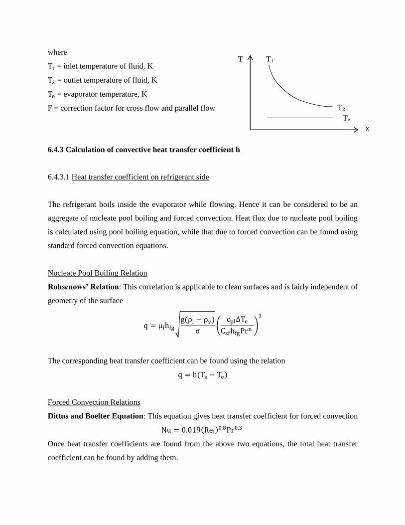
where
T1 = inlet temperature of fluid, K
T2 = outlet temperature of fluid, K
Te = evaporator temperature, K
F = correction factor for cross flow and parallel flow
6.4.3 Calculation of convective heat transfer coefficient h
6.4.3.1 Heat transfer coefficient on refrigerant side
The refrigerant boils inside the evaporator while flowing. Hence it can be considered to be an
aggregate of nucleate pool boiling and forced convection. Heat flux due to nucleate pool boiling
is calculated using pool boiling equation, while that due to forced convection can be found using
standard forced convection equations.
Nucleate Pool Boiling Relation
Rohsenows’ Relation: This correlation is applicable to clean surfaces and is fairly independent of
geometry of the surface
q = µlhfg√g(ρl − ρv)
σ(
cpl∆Te
CsfhfgPrn)
3
The corresponding heat transfer coefficient can be found using the relation
q = h(Ts − Te)
Forced Convection Relations
Dittus and Boelter Equation: This equation gives heat transfer coefficient for forced convection
Nu = 0.019(Rel)0.8Pr0.3
Once heat transfer coefficients are found from the above two equations, the total heat transfer
coefficient can be found by adding them.
T1
T2
Te
T
x

Combined Flow Boiling Equations:
Bo-Pierre’s Equation: This equation can be used when the inlet dryness is greater than 0.1 and
less than 0.16
Nu = 0.0082(Re2Kf)0.5
Kf is called load factor, given by the equation
Kf =∆xhfg
L
Legend for conventions used in this section are:
q = heat flux, W/m2
µl = viscosity of refrigerant, Pa.s
hfg = latent heat of vaporization of refrigerant, J/kg
g = acceleration due to gravity, m2/s
ρl = density of liquid refrigerant, kg/m3
ρv = density of vapour refrigerant, kg/m3
σ = surface tension, N/m
cpl = specific heat of refrigerant, J/kgK
∆Te = Ts − Te
Ts= surface temperature of tubing, K
Te = evaporation temperature of the refrigerant, K
Pr = Prandtl number of the refrigerant
n = a constant (usually 1.7)
Csf = constant, 0.013 for halocarbons
Nu= Nusselt number, hD
k
Rel = Reynolds number of liquid refrigerant, ρlvD
μl
v = velocity of refrigerant, m/s
L= length of the tube, m
x = dryness fraction
∆x = change in dryness fraction

6.4.3.2 Heat transfer coefficient on the fluid side
The heat transfer c
6.5 Design procedure for thermostatic expansion valve
Determine the evaporator temperature Te and the degree of superheat ∆Ts.
Find out the saturation pressures, psat (Te) and psat (Te + ∆Ts) of the refrigerant at Te and
Te + ∆Ts, either from standard refrigeration tables or using Antoine’s equation for R134a
psat = e14.41−2094
T−33.06
where psat is in kPa and T is in K
Find out the required adjustable spring pressure:
ps = psat(Te + ∆Ts) − psat(Te)
Based on the required deflection of spring, find out the area of the bellows:
Ab =Fsps
Related Documents