General rights Copyright and moral rights for the publications made accessible in the public portal are retained by the authors and/or other copyright owners and it is a condition of accessing publications that users recognise and abide by the legal requirements associated with these rights. • Users may download and print one copy of any publication from the public portal for the purpose of private study or research. • You may not further distribute the material or use it for any profit-making activity or commercial gain • You may freely distribute the URL identifying the publication in the public portal If you believe that this document breaches copyright please contact us providing details, and we will remove access to the work immediately and investigate your claim. Downloaded from orbit.dtu.dk on: May 27, 2018 Solid fuel interactions in co-combustion a literature survey Wu, Hao; Jappe Frandsen, Flemming; Dam-Johansen, Kim Publication date: 2011 Document Version Publisher's PDF, also known as Version of record Link back to DTU Orbit Citation (APA): Wu, H., Jappe Frandsen, F., & Dam-Johansen, K. (2011). Solid fuel interactions in co-combustion: a literature survey. Technical University of Denmark, Department of Chemical Engineering.

Welcome message from author
This document is posted to help you gain knowledge. Please leave a comment to let me know what you think about it! Share it to your friends and learn new things together.
Transcript

General rights Copyright and moral rights for the publications made accessible in the public portal are retained by the authors and/or other copyright owners and it is a condition of accessing publications that users recognise and abide by the legal requirements associated with these rights.
• Users may download and print one copy of any publication from the public portal for the purpose of private study or research. • You may not further distribute the material or use it for any profit-making activity or commercial gain • You may freely distribute the URL identifying the publication in the public portal
If you believe that this document breaches copyright please contact us providing details, and we will remove access to the work immediately and investigate your claim.
Downloaded from orbit.dtu.dk on: May 27, 2018
Solid fuel interactions in co-combustiona literature survey
Wu, Hao; Jappe Frandsen, Flemming; Dam-Johansen, Kim
Publication date:2011
Document VersionPublisher's PDF, also known as Version of record
Link back to DTU Orbit
Citation (APA):Wu, H., Jappe Frandsen, F., & Dam-Johansen, K. (2011). Solid fuel interactions in co-combustion: a literaturesurvey. Technical University of Denmark, Department of Chemical Engineering.

Solid fuel interactions in co-combustion – a literature survey
Hao Wu, Peter Glarborg, Flemming Jappe Frandsen, Kim Dam-Johansen
May, 2011
CHEC Research Centre
Department of Chemical and Biochemical Engineering
Technical University of Denmark
Søltofts Plads, Building 229, DK-2800 Kgs.Lyngby, Denmark
Phone: 45 25 28 00

i
Table of Contents
1. Introduction ...................................................................................................................................... 1
2. Combustion fundamentals and gaseous emissions .......................................................................... 2
2.1 Devolatilization .......................................................................................................................... 2
2.2 Ignition and flame stability ......................................................................................................... 5
2.3 Char reactivity and burnout ........................................................................................................ 6
2.4 NOx emission .............................................................................................................................. 9
2.5 SOx emission ............................................................................................................................ 12
3. Ash formation, deposition and utilization ...................................................................................... 14
3.1 Ash forming elements in solid fuels ......................................................................................... 14
3.2 Association of ash forming elements ....................................................................................... 17
3.3 General ash formation mechanism ........................................................................................... 21
3.4 Release of ash forming elements .............................................................................................. 22
3.5 Interactions in ash chemistry .................................................................................................... 28
3.5.1 Reactions between vaporized alkali metals and kaolinite ................................................. 29
3.5.2 Reactions between vaporized alkali metals and other minerals ........................................ 30
3.5.3 Reactions between alkali metals and gaseous sulphur ...................................................... 32
3.5.4 Ash interactions during co-combustion of coal and high alkali biomass/waste ................ 33
3.6 Fine particle formation ............................................................................................................. 35
3.6.1 Fine particle formation in pulverized coal combustion ..................................................... 36
3.6.2 Fine particle formation in pulverized biomass combustion ............................................... 37
3.6.3 Fine particle formation in co-combustion o f pulverized coal and biomass ...................... 39
3.7 Ash deposition .......................................................................................................................... 40
3.7.1 Ash deposition mechanisms .............................................................................................. 40
3.7.2 Influence of co-combustion on deposition rate/tendency .................................................. 41
3.7.3 Influence of co-combustion on deposit properties ............................................................. 42
3.8 High temperature corrosion ...................................................................................................... 44
3.8.1 Corrosion mechanisms....................................................................................................... 44
3.8.2 Influence of co-combustion on corrosion .......................................................................... 45
3.9 Fly ash utilization ..................................................................................................................... 46
References .......................................................................................................................................... 48

1
1. Introduction
Direct co-combustion of coal and secondary fuels in existing coal-fired power plants is regarded as an advantageous approach to replace part of the fossil fuel consumption by more CO2-friendly fuels such as biomass and waste. The major advantages of this technique have been summarized by several reviews available on this subject [1-8]. Compared to dedicated biomass- or waste-fired plants, the addition of biomass or waste to high efficiency coal-fired power plants can greatly increase the electrical efficiency of utilizing these fuels [4]. Besides, the cost of retrofitting an existing coal-fired power plant to a co-combustion plant can be considerably lower than building a new dedicated biomass- or waste-fired plant [9]. Furthermore, co-combustion can be operated in a flexible mode (i.e. with different share of secondary fuels) which can minimize the fluctuating supply of some secondary fuels (such as straw) and secure the power generation [1].
Although with many advantages, co-combustion may involve a number of technical issues which need to be addressed [1,3,4]. For example, the cost of co-combustion may be considerably higher than that of dedicated coal combustion due to the relatively high price of the secondary fuels (including the transportation expense) and the cost associated with the required pretrements (such as drying, grinding and densification). In addition, co-combustion of coal and a secondary fuel in a coal-fired power plant may affect the performance of the plant, and lead to problems associated with ash deposition, fuel conversion, pollutant formation (such as NOx, SO2, and fine particles), corrosion, and fly ash utilization [4]. These issues have been the major technical barriers of co-combustion, and have become the topics of extensive research in the past two decades. In addition, with the growing interest in utilizing biomass and waste in heat and power production, the understanding of the fundamentals of biomass and waste combustion has improved considerably in recent years through extensive research. These advances, together with the relatively well-established knowledge on coal combustion, can generally allow us to achieve a good understanding on the co-combustion processes.
This review aims to provide an outline of the fundamental fuel and ash conversion processes during co-combustion of coal and different secondary fuels, particularly at conditions relevant to pulverized fuel combustion. Through a detailed assessment of the differences and interactions of coal and various secondary fuels in different fuel/ash conversion processes, the possible effect of co-combustion on a number of technical aspects, such as ignition, burnout, pollutants formation, ash deposition, corrosion, and ash utilization, are evaluated and interpreted based on literature.

2
2. Combustion fundamentals and gaseous emissions
2.1 Devolatilization
When a solid fuel particle is exposed to a high temperature environment, the organic structure can undergo thermal decomposition and release volatile matter. This process is described as devolatilization, with the major products containing light gases (mainly CO2, CO, H2O, H2, CH4 and other light hydrocarbons), tar/soot and char. The characteristics of devolatilization, such as decomposition temperature, rate and product distributions, can subsequently influence the ignition, burnout and pollutant formation during solid fuel combustion [10-12].
The devolatilization behavior of coal has been well characterized through experiments and modeling, with several detailed reviews available on this subject [10,11,13]. The major organic structures in coal can be categorized as aromatic clusters, side chains, aliphatic bridges and loops [14]. During the primarily devolatilization, the aromatic clusters are largely converted to tar and char, while the other organic structures are the main precursors of light gases [11]. The product distribution from the primary devolatilization of coal is influenced by factors such as coal properties (rank), heating rate, environmental temperature and pressure. The coals with lower rank generally produce more light gases during the primary devolatilization [10,15-18], due to the presence of smaller amount of aromatic carbon and larger amount of aliphatic chains. The formation of tar is usually most significant for the devolatilization of intermediate-rank coals (such as bituminous coals) [10,15-18], as these coals contain more aliphatic chains than the high-rank coals (such as anthracite) and more aromatic carbon than the low-rank coals (such as lignite), which favor tar formation. The formation of light gases such as CO, CO2 and CH4 during the primary devolatilization is reported to be promoted by increasing the temperature of the pyrolysis environment [19,20]. The formation of tar may also increase with increasing environmental temperature [19,20], whereas the effect may become insignificant when the temperature is above 800 oC [20]. When the primary devolatilization is carried out at elevated pressure, the formation of tar as well as the total volatile species can be inhibited to some extent [10].
Once the tar and light gases are released from the primary devolatilization of coal, they may undergo secondary reactions and produce soot and different light gases [21-24]. The secondary reactions of tar usually involve thermal cracking and/or soot formation. During the thermal cracking, the side chains and functional groups in the tar are cracked to produce light gases [25]. On the other hand, the main mechanisms of soot formation are considered to be the direct conversion of tar and the addition of light gases to soot [21].
Compared to coal, biomass and waste are often characterized by a higher volatile content and a lower char content [26]. Extensive research has been carried out on devolatilization of biomass and waste [27-31]. For biomass and biomass-originated waste, such as waste wood and paper, the major organic components are usually cellulose, hemicellulose and lignin [26,27]. During the devolatilization, the hemicellulose often decomposes at lower temperature compared to cellulose, and produces more volatiles, less tar and less char. Lignin is an amorphous cross-linked resin, which can produce more char during devolatilization than that of cellulose or hemicellulose [27]. Due to the structural differences between biomass and coal, their devolatilization characteristics are usually quite different. A typical example is given in Figure 1, showing that the devolatilization of the biomass mixture occurs at much lower temperature than that of coal, and produces much more light gases and tar. The devolatilization of biomass is greatly influenced by the biomass properties

3
and the process parameters such as environmental temperature and heating rate [28]. A higher environmental temperature usually inhibits the char yield and promotes the light gas formation. The maximum yield of tar is often observed at intermediate environmental temperature range (~500–700 oC), which is related to both the primary release and secondary reactions of tar [28]. More detailed investigations on biomass devolatilization are summarized in [27,28].
An important constituent of waste materials is highly polymerized materials such as plastics and rubbers. Compared to biomass, devolatilization of plastics and rubbers generally occurs at higher temperature and produces more volatiles. According to the thermogravimetric analysis (TGA), the devolatilization of various plastics primarily takes place in the temperature range of ~400–550 oC, while the devolatilization of biomass (lignocellulosic materials) mainly happens in the temperature range of ~200–400 oC [29-31]. PVC (Polyvinylchloride) is a special type of plastics, which starts to decompose at lower temperatures than most other plastics [29-32]. The devolatilization of PVC primarily follows two steps. The first step (dehyrochlorination) occurs in the temperature range of ~200–370oC, in which a fraction of hydrocarbons is released as benzene and the Cl is almost fully released as HCl. The second step takes place in the temperature range of ~400–500oC, which is accompanied by the evolution of toluene and alkyl aromatics [29-32].
Figure 1 Mass loss and product distribution during devolatilization of a bituminous coal and a biomass mixture at a heating rate of 30 oC/min, adapted from [33].
The interactions between coal and biomass/waste during devolatilization have been investigated through TGA, fixed-bed, and entrained flow experiments [34-43]. A number of studies show that the interactions between coal and biomass/waste are negligible during the devolatilization [34,39,41,43,44], suggesting that the devolatilization behavior of the fuel mixture is additive (i.e. no obvious synergy effect between the fuels). On the other hand, some others report that small interactions may exist, when coal is pyrolyzed together with biomass/waste [35,36,38,40,42]. The mechanisms which may cause the interactions are discussed in the following.
When coal is pyrolyzed together with biomass, the volatiles released from biomass may react with coal or coal volatiles. These reactions may promote the formation of volatiles from the fuel mixture,

4
and meanwhile inhibit the char yield [36,38,40,42]. A possible explanation is that the devolatilization of typical biomass/waste may produce relatively large amount of H2, which can prevent the recombination and cross-linking reactions of free radicals, thereby suppressing the char formation [36]. Alternatively, the free radicals such as H* and CH3* originated from the decomposition of aliphatic components of coal may react with the methoxyphenolic compounds from biomass devolatilization and form benzene substitutes [38]. The presence of such reactions may influence the distribution of volatile products from co-pyrolysis, and result in an increased formation of tar [35,42]. However, the extent of the secondary reactions among the released volatiles and the fuel mixture are to a large extent dependent on their mixing level and contacting time [39]. This may be an explanation to the insignificant synergy effect reported in other co-pyrolysis experiments [34,39,41,43,44]. The extent of synergy may be also dependent on the characteristics of the fuels, such as coal rank and biomass properties [37,40].
Besides the organic species, inorganic elements in biomass/waste may induce certain interactions during co-pyrolysis of coal and biomass/waste, since these elements may catalyze solid fuel devolatilization [45-47]. When biomass is demineralized, the initial devolatilization temperature is often increased compared to that of raw biomass, indicating that the cations in biomass, such as Ca, Mg, and K, may catalyze fuel decomposition to start at lower temperatures. Besides, the demineralization process may affect the distribution of the devolatilization products and result in an increased formation of volatiles [45-47]. As a result, when coal is co-pyrolyzed with biomass/waste of high ash content, the catalytic effect of inorganic elements may lead to interactions. As an example, during co-pyrolysis of coal and MBM (meat and bone meal), the DTG (derivative thermogravimetric analysis) curve of the mixture is found to be shifted to lower temperature, compared to that calculated from the pure fuels. This is partly explained by the catalytic effect of the inorganic elements in MBM, as the interactions are weakened in a mixture of demineralized MBM and coal [48].
Synergy effects have also been observed when coal is pyrolyzed with plastic materials, such as LDPE (low density polyethylene) and PP (polypropylene) [49-51]. At temperatures lower than the decomposition temperature of plastics, the devolatilization of the mixture is reported to be inhibited, which is probably because the softening and melting of plastics may inhibit the evolution of volatile matter during coal pyrolysis [49,51]. However, when the temperature becomes higher than the decomposition temperature of the plastics, the devolatilization of the mixture may be promoted and result in an increased formation of volatiles [49,51]. A possible explanation is that the hydrocarbon species originated from cleavage of polymer bonds may react with the radicals from coal thermal decomposition, which stabilize the primary decomposition products and thereby promote the formation of volatiles [49].
The presence of PVC in fuel mixtures may significantly affect the devolatilization behavior of other solid fuels, particularly for the lignocellulosic materials [30,52]. Co-pyrolysis of PVC and lignocellulosic materials may lower the decomposition temperature of the lignocellulosic materials and increase the char yield [30,52]. These interactions are primarily linked to the HCl released from the dehyrochlorination of PVC. The evolution of HCl may facilitate dehydration and aldehyde formation from the lignocellulosic materials, which could inhibit depolymerization and thereby promote the char formation [52].
It should be noted that the majority of the interactions during co-pyrolysis of coal and biomass/waste are observed during TGA experiments, in which fuel particles are intimately contacted and the heating rate is relatively slow. In the case of co-pyrolysis at suspension-fired
5
conditions, the extent of interactions may be limited, due to the constraints in mixing and contacting time among the fuel particles and the volatiles.
2.2 Ignition and flame stability
During solid fuel combustion, ignition and flame stability are important for carbon burnout and formation of pollutants such as NOx [53,54]. The ignition of solid fuel particles can follow two mechanisms, i.e. heterogeneous ignition and homogeneous ignition. The heterogeneous ignition usually results from the direct attack of oxygen on the fuel/char particle surface, while the homogeneous ignition describes the ignition of the volatiles released from the fuel particles [53,54]. The ignition characteristics of solid fuels, including ignition mechanism, time (delay) and temperature, are influenced by a number of factors such as fuel characteristics, particle size/shape, ambient temperature/heating rate, ambient gas compositions, particle number density and fluid flow [53-59].
In co-combustion of pulverized coal and biomass, the applied biomass particles are usually considerably larger than the coal particles [3,60-62]. Biomass is more difficult and costly to grind than coals [3,9], and the characteristics of biomass (such as the high volatile content) allows it to have a relatively large particle size in co-combustion. Due to the differences in particle size and in the inherent fuel characteristics, the ignition behavior of biomass and coal particles may be quite different, which can influence the flame characteristics in co-combustion.
With the purpose of comparing the ignition/flame characteristics of pulverized coal and biomass (sawdust), experiments have been conducted in a semi-industrial-scale reactor [63]. Compared to the coal flame, a more intense and wide flame is observed near the burner during the sawdust combustion, which is attributed to the volatiles released from the fine fraction of sawdust particles. On the other hand, a second flame stage appears downstream of the near-burner region during sawdust combustion, which is presumably related to the combustion of the large sawdust particles. These large sawdust particles usually require more devolatilization time and could more easily penetrate the IRZ (internal recirculation zone) of the burner compared to the coal particles [63].
A similar two-stage flame has been seen during co-combustion of coal and straw [64], as indicated by the O2 and CO distributions shown in Figure 2. Particle sampling suggests that the second flame stage results from the large and dense straw knee particles. These particles can have sufficient momentum to penetrate the IRZ of the burner [65], and the large particle size may cause a significant intra-particle temperature gradient which prolongs the devolatilization process [66]. By decreasing the primary air flow (i.e. inertia of straw particles), the flame is found to be shortened and the second flame stage disappears, suggesting that the flame structure in co-combustion is largely dependent on the injection method of biomass [64]. This is supported by the experiments carried out in a down-fired furnace, showing that the injection method of biomass can greatly affect the burnout and NO emissions [67].
The influence of co-firing coal and different biomass on the flame temperature, stability and other characteristics has been investigated by using vision-based measurement techniques on an industrial-scale combustion test facility [68]. The addition of 10% (thermal basis) biomass generally resulted in a delayed ignition of the fuel particles compared to the coal flame. This is presumably a result of the relatively large particle size and high moisture content of the biomass particles. For biomass with smaller moisture content, the ignition time is shorter than that of other co-combustion experiments. The brightness of the co-firing flames is consistently higher than that of coal flames,

6
presumably because biomass may generate more soot with high radiant intensity. The oscillation of the co-firing flames is quite similar to a coal flame, indicating that the flame stability is not significantly affected when part of the coal is replaced by biomass [68]. The temperature of the co-firing flame is slightly greater than that of coal flame, which is attributed to a faster heat release caused by the volatiles from biomass [68]. Similar increased flame temperature is observed when coal is co-combusted with sawdust in an electrically heated drop tube reactor [69].
Figure 2 O2 and CO distributions in a flame of co-firing coal and straw (50% thermal basis); the straw was injected through a center tube with an air flow of 16.5 kg/h and the coal was injected via an annular tube with an air flow of 15.0 kg/h [64].
In general, the influence of adding biomass to a coal flame is to a large extent dependent on the physical and chemical properties of the biomass particles and their injection method. The relatively large size of biomass particles, together with a high moisture content, may result in a delayed ignition [68] or devolatilization [64,66]. If the delayed devolatilization is associated with a significant momentum of large biomass particles, it may result in a two-stage flame structure [63,64]. Besides, biomass usually contains relatively large volatile content and starts to decompose at lower temperatures [70], which is a favorable condition for generating a more intensive flame than coal flame [63,64,68,69]. The injection method of biomass particles also significantly affects the extent of fuel interactions, and subsequently impacts the ignition and flame characteristics during co-combustion [64,67,68].
2.3 Char reactivity and burnout
The degree of carbon burnout refers to the fraction of combustion matter in the parent fuel that is converted to gaseous products, with the remainder being left as carbonaceous residue [71]. In pulverized fuel combustion, the carbon burnout does not only influence the thermal efficiency of the plant, but also affects the quality of fly ash to be used in cement or concrete production [71,72]. The typical combustion history of a solid fuel particle is illustrated in Figure 3. It can be seen that the characteristic time of char oxidation is much longer than that of heating or devolatilization. Therefore the burnout in pulverized fuel combustion is to a large extent dependent on the char reactivity of the fuel particles.

7
Figure 3 Typical combustion history of a biomass particle (switchgrass), also representative for a coal particle [3].
The global reactivity of a char particle is governed by the mass and heat transport across the external boundary layer of the particle, by the mass and heat transport through the porous structures of the particle, and by the chemical reactions occurring between oxygen and the carbonaceous surfaces within the particle [28]. In general, the combustion of char particles can follow three regimes [28,71].When the diffusion rate is much faster than the chemical reaction rate, the combustion of char particles follows the regime I (kinetic control), which is usually established for low temperatures and small char particles. For the regime II, the chemical reaction rate becomes comparable with the pore diffusion rate. Thus the char combustion is controlled both by pore diffusion and chemical reaction. For the regime III, the char combustion is controlled by the diffusion from the bulk gas to the external surface of the particle [28,71]. During pulverized fuel combustion the char oxidation generally follows the regime I and II, whereas the regime III is often favored by fixed-bed combustion where larger particles are combusted [71].
The reactivity of char particles can be influenced by various factors such as fuel characteristics, heating rate, temperature, and pressure [28,71]. For co-combustion where different fuel particles are combusted at similar conditions, the discrepancy in the char reactivity of different fuel particles is largely attributed to the fuel characteristics. A comparison of the char reactivity of different solid fuels has been performed through TGA experiments at kinetic control conditions (regime I) [73]. Figure 4 shows the obtained reactivities for 17 char samples prepared at 1000 oC. The reactivities of different solid fuels vary almost 4 orders of magnitude under identical conditions. For coal chars, the char reactivity generally decreases with increasing carbon (daf) content of the coals, which is consistent with the tendency observed in another study [71]. The reactivity of biomass chars is generally greater than that of coal chars, which is in agreement with several other studies [74-77]. Since the non-catalytic model/pure materials (such as cellulose) shown in Figure 4 exhibit uniformly low char reactivity, the variations of the char reactivity of biomass and coal samples are primarily attributed to the catalytic effect of the inorganic elements (such as Ca, Mg and K) present in these fuels. The char surface area can also influence the reactivity, but this effect is believed to be less significant compared to the catalytic effect of the inorganic elements at the given experimental conditions [73].

8
Figure 4 Measured reactivity of chars prepared at 1000 oC from 17 samples versus the carbon content (daf) of the fuels [73].
To investigate the catalytic effect of inorganic elements on char reactivity, Zolin et al. have carried out a detailed investigation on the char reactivity of a straw and a low rank coal [78]. For the char samples produced in a TGA, the catalytic effect of the inorganic elements appears to be significant both for the straw and the coal at heat treatment temperatures up to 1000 oC, as reflected by a much lower char reactivity of the demineralized coal and washed straw compared to raw fuels. However, when the char is produced in the TGA at temperatures higher than 1200 oC, the catalytic effect of the inorganic elements is reduced, which is interpreted by the transformation of the inorganic elements and/or the char thermal deactivation such as annealing. On the other hand, for the char produced in an entrained flow reactor (EFR) at 1200 oC/1400 oC, the reactivity of the char from raw straw is still about 30-40 times higher than that of leached straw, indicating that the reduction of the catalytic effect at high temperatures is insignificant at this condition. A possible explanation is that the time scale of the heating stage in the EFR may be shorter than that needed for the deactivation or vaporization of the inorganic catalysts. In addition, the char sampling method in the EFR may recombine inorganic aerosols such as KCl on the char surfaces [78].
Although the reactivity of biomass char particles is generally greater than that of coals [73-78], the carbon burnout in co-combustion of coal and biomass is affected by other factors, such as the residence time, the shape, and the ignition/heating characteristics of fuel particles. The investigations on the influence of co-combustion on the burnout have been carried out on with a number of different coals and biomass [79-81]. Depending on the fuel characteristics and combustion environment, co-combustion of coal and biomass may either increase or decrease the burnout, compared to dedicated coal combustion.
During co-combustion of coal and straw in a pulverized coal-fired power plant [79], the unburnt carbon in the fly ash is found to decrease progressively with increasing share of straw. On the other hand, the unburnt carbon in the bottom ash is increased with increasing share of straw, which is interpreted as a result of insufficient residence time for some dense straw particles [79]. Similar results are obtained during co-combustion of pulverized coal and sawdust in a full-scale plant [80],
9
showing that the residue carbon in fly ash is decreased by the addition of sawdust and some large unburnt wood particles are seen in the bottom ash. The beneficial effect of biomass addition on the burnout is also observed during co-combustion of lignite and sawdust in an isothermal flow reactor [81], during co-combustion of coal and a number of different biomass in a down-fired combustor [82], and during co-combustion of different coal and biomass both under air and oxy-fuel combustion conditions [83]. In general, the observed effect is likely a combination of several factors. Because of the catalytic effect of inorganic elements and the porous structure, the reactivity of biomass char is usually greater than that of coal char [73-78]. Besides, the biomass char particles are usually non-spherical and have large aspect ratios, which are more favorable in terms of heat transfer and residence time, compared to the equivalent spherical particles [84]. The possible higher flame temperature during co-combustion of coal and biomass may also be an advantage for the burnout [68,69]. Moreover, during co-combustion of coal and biomass, the particle size of biomass char is often larger than that of coal char, which can result in a higher slip velocity between char particles and local gas [3]. Therefore, in the same boiler, the residence time of a biomass char may be longer than that of coal char, and result in an increased burnout.
In contrast to the enhancing effect, some studies show that the addition of biomass can reduce the burnout during co-combustion. The experiments in a pulverized fuel combustion test facility reveal that co-combustion of coal and biomass (straw/wood/miscanthus) results in a reduced burnout compared to dedicated coal combustion [9]. The observed decreased burnout is primarily attributed to the large biomass particle size used in the experiments and the relative short residence time in the test facility [9]. Similar decreased burnout is observed when coal is co-fired with wood in a pulverized coal-fired power plant [85]. Generally, the decreased burnout during co-combustion of coal and biomass is most likely linked to the large particle size and high moisture content of the biomass particles, which may delay the devolatilization and subsequently the char oxidation processes [66]. Selection of biomass with suitable particle size and moisture content is therefore of key importance to ensure a satisfactory burnout in co-combustion of coal and biomass [3,9].
2.4 NOx emission
The formation of NOx during solid fuel combustion mainly follows three mechanisms, namely thermal NO, prompt NO, and fuel NO [12]. The thermal NO is formed from the reactions between N2 and O2, according to the so called extended Zeldovich mechanism:
2O N NO N (1.1)
2N O NO O (1.2)
N OH NO O (1.3)
The prompt NO formation is initiated by the attacking of hydrocarbon radicals on the N2 triple bond. The reactions can generate cyanide species which can be subsequently oxidize to NO [12].
The fuel NO is formed from the oxidation of the nitrogen species present in solid fuels. When solid fuels are exposed to high temperature, the nitrogen species are released as volatiles or retained in char during the devolatilization stage. The volatile-N released from primary devolatilization consists of light gases (mainly HCN and NH3) and tar-N. The tar-N may be decomposed to light gases and soot-N during secondary devolatilization. With the presence of oxygen, the nitrogen in char, soot and light gases may be oxidized to NO or recycled to N2. The comprehensive fuel-N conversion processes during solid fuel combustion have been reviewed in [12]. The emphasis here is on identifying the possible interactions on NOx formation during co-combustion of different solid

10
fuels, especially coal and biomass.
For coal and biomass, the characteristics of the nitrogen species released during devolatilization are usually quite different, with respect to the onset decomposition temperature and product distributions. The release of volatile-N during biomass devolatilization may start at lower temperatures than that of coal [12,86-89]. The release of volatile-N may begin at 200-300 oC during biomass devolatilization and up to about 50-80% of the fuel-N may be released as volatile-N at 500 oC [86]. However, for coal, the onset temperature for volatile-N release is usually about 500-600 oC [33,86]. This difference may be attributed different initial devolatilization temperatures of coal and biomass, which has been discussed previously, with a typical example given in Figure 5. Besides the onset temperature, the distribution of nitrogen products from coal and biomass devolatilization may also be different. A typical example of the distribution of nitrogen species from coal and biomass (chicken litter) devolatilization is given in Figure 5. It shows that the formation of gas-N during the biomass devolatilization is much more pronounced than that of coal, whereas the devolatilization of coal produces significantly more tar-N and slightly more char-N [33]. Other studies also support that the formation of gas-N during biomass devolatilization is more pronounced compared to coal [33,87,90]. The major gas-N species from coal/biomass devolatilization are HCN and NH3. Compared to coal, biomass devolatilization may evolve more NH3 [12]. This is presumably related to the presence of amino groups in biomass which may directly yield NH3 through thermal decomposition [90]. In addition, biomass may have more oxygen functional groups that that of coal, which is a favorable condition for the hydrogenation of NH3 from HCN [12].
Figure 5 Partitioning of fuel nitrogen between gas, tar and char for coal and chicken litter obtained from an experiment carried out at a wire mesh reactor at 1300 oC [33].
The variations in the distribution of nitrogen species from biomass and coal devolatilization may lead to some interactions for the NOx formation during co-combustion. In addition, the formation of NOx during co-combustion is closely related to the flame characteristics, which are affected by the properties and injection method of the secondary fuels. Therefore, the observed effect of co-combustion on NOx formation is often resulted from a combination of several factors. The formation of NOx during co-combustion of straw and different coals has been studied in a pilot-scale reactor and a full-scale pulverized coal-fired power plant [91]. As shown in Figure 6, the conversion of fuel-N to NO generally decreases with increasing shares of straw. This is conceivably
0
20
40
60
80
100
Gas-N Tar-N Char-N
Wei
ght
%
Coal
Chicken litter

11
related to the higher volatile and fuel-N release at the near-burner region, which may lower the excess air ratio in the region and thereby reduce the NO formation. In addition, the observed darker flame (lower flame temperature) with increasing share of straw may also be a possible reason for the reduced NO formation. Compared to the low NOx flames, the effect of straw addition seems to be even more pronounced for the high NOx flames, suggesting that burner configuration may be important to the NOx formation in co-combustion [91]. Similar reducing effect of biomass addition on the conversion of fuel-N to NO during co-combustion has been reported in other studies [7,60,82,92], which generally support the results shown in Figure 6. The influence of burner configuration and air staging on NOx formation during co-combustion is investigated [9,82]. It appears that air staging may enhance the reducing effect of biomass on NOx formation, if the residence time in the reducing zone is sufficiently long for completing the devolatilization of biomass [9]. The influence of burner configurations on the NOx formation may be dependent on the characteristics of secondary fuels, as different burner mode is favored when coal is co-fired with straw or sewage sludge [9].
Figure 6 Conversion of fuel-N to NO (%) during co-combustion of different coal and straw under pulverized combustion conditions. Solid symbols denote the results from high NOx flames, while the open symbols denote the results from low NOx flames [91].
It is worthwhile to mention that the reduced conversion of fuel-N to NO obtained during co-combustion of coal and biomass may not necessarily indicate the presence of net interactions between coal and biomass on NOx formation. As shown in Figure 6, the conversion of fuel-N to NO is lower for pure straw combustion than that for coal combustion. Therefore, the observed reduced fuel-N conversion may simply be an additive effect, since the fuel-N in biomass may have a lower propensity to generate NOx than that of coal. The experiments carried out by Robinson et al. support that the net interactions of coal and biomass on NOx emission are insignificant [93], suggesting that the fuels in co-combustion may behave as they are combusted in isolation. However, the experimental results of Robinson et al. are obtained under carefully controlled combustion conditions [93]. In practical applications, the addition of secondary fuels may influence the temperature and stoichiometry of combustion, and certain interactions may exist. A significant reduction on NOx formation may be achievable through optimizing the burner configurations and
0
10
20
30
40
50
60
70
80
0 20 40 60 80 100
Fu
el-N
con
vers
tion
to
NO
(%
)
Straw share (% thermal)
12
air staging during co-combustion [9,82]. In addition, biomass may also be applied as a reburn fuel to minimize the NOx emission [94,95].
2.5 SOx emission
During solid fuel combustion, the sulphur in the fuel may be converted to gaseous SO2/SO3 or partitioned to ash/aerosols. Global equilibrium calculations show that SO2 is the only stable sulphur species at temperatures above 1200 oC during pulverized fuel combustion at oxidation condition [96]. At lower temperatures, part of the SO2 may be transformed to solid phase, through reacting with inorganic elements such as Ca and K. In addition, a small fraction of SO2 may be oxidized to SO3, which may be further condensed as sulfuric acid at certain conditions [97]. However, the formation of SO3 during pulverized fuel combustion is generally limited to about 0.5-1.5% of the fuel-S [97]. Thus the major SOx emission from pulverized fuel combustion is SO2, and the major mechanism for reducing the SO2 emission during combustion is the reaction between SO2 and other ash forming elements.
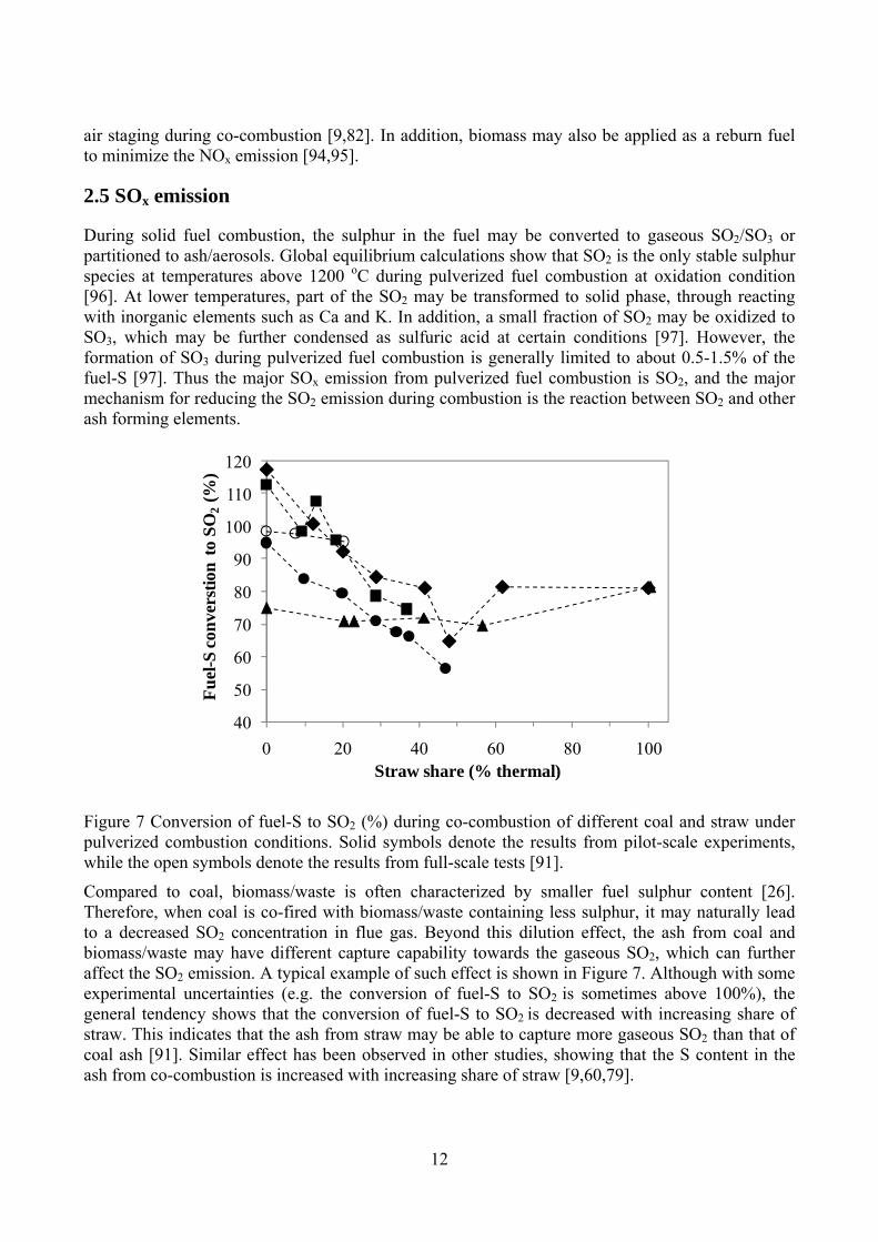
Figure 7 Conversion of fuel-S to SO2 (%) during co-combustion of different coal and straw under pulverized combustion conditions. Solid symbols denote the results from pilot-scale experiments, while the open symbols denote the results from full-scale tests [91].
Compared to coal, biomass/waste is often characterized by smaller fuel sulphur content [26]. Therefore, when coal is co-fired with biomass/waste containing less sulphur, it may naturally lead to a decreased SO2 concentration in flue gas. Beyond this dilution effect, the ash from coal and biomass/waste may have different capture capability towards the gaseous SO2, which can further affect the SO2 emission. A typical example of such effect is shown in Figure 7. Although with some experimental uncertainties (e.g. the conversion of fuel-S to SO2 is sometimes above 100%), the general tendency shows that the conversion of fuel-S to SO2 is decreased with increasing share of straw. This indicates that the ash from straw may be able to capture more gaseous SO2 than that of coal ash [91]. Similar effect has been observed in other studies, showing that the S content in the ash from co-combustion is increased with increasing share of straw [9,60,79].
40
50
60
70
80
90
100
110
120
0 20 40 60 80 100
Fu
el-S
con
vers
tion
to
SO
2(%
)
Straw share (% thermal)

13
The effect of straw addition on the fuel-S conversion in co-combustion is mainly attributed to the high ash and K content of straw [91]. When a secondary fuel with low ash and sulphur content (such as wood) is applied, it probably has a negligible impact on the fuel-S conversion during co-combustion [98]. Besides the properties of the secondary fuel, the fuel injection method and other combustion conditions may also play a role on the fuel-S conversion during co-combustion. Through comparing the experimental results with the predictions of global equilibrium calculations [91], it seems that the reactions between SO2 and other ash forming elements are kinetically limited. Therefore, if sufficient mixing and long residence time can be provided, the effect of the secondary fuel on fuel-S conversion may become more significant, and vice versa.

14
3. Ash formation, deposition and utilization
Ash related issues such as slagging, fouling, corrosion and particulate emissions are of significant concerns in co-combustion of solid fuels. This is mainly because the secondary fuels applied in co-combustion, such as agricultural residues and waste-derived fuels, usually contain large amount of alkalis and chlorine that may be easily released to gas phase during combustion. The released alkali and chlorine may generate alkali chlorides and may cause severe ash deposition and corrosion on the heat transfer surfaces. In addition, the vaporized inorganic elements are a major precursor of the aerosols generated from combustion. These aerosols are not only the main source of particular matters emitted to the environment, but also a major reason for the deactivation of SCR units in the plant. Therefore, it is critical to understand and address the ash related problems in co-combustion. With this objective, the fundamentals on ash formation, deposition, corrosion and utilization in solid fuel combustion are reviewed in this section. In addition, the possible interactions among different solid fuels on ash related issues are also evaluated. It should be noted that the present section mainly focuses on the behavior of the major ash forming elements in co-combustion, since these elements dominate the ash formation.
3.1 Ash forming elements in solid fuels
The ash forming elements that are significantly concerned during co-combustion of coal and biomass/waste are K, Na and Cl, since the ash related problems mentioned earlier are to a large extent induced by these elements. Despite of the diverse nature of coal, biomass and waste, the content of K, Na and Cl in these fuels shows some general tendency, which may be related to the origins/biological features of these fuels. Figure 8 shows the concentrations of ash, alkali (K+Na), and Cl in several different groups of biomass, waste and coals. These biomass/waste are chosen because they are extensively used in co-combustion [93,99-104]. Although the data shown in Figure 8 are comprehensive, they can still reveal some general features of these fuel groups. The features observed are: (1) woody biomass is generally of the lowest ash, alkali and Cl content among the fuel groups; (2) grasses usually have slightly larger ash, alkali and Cl content than that of woody biomass; (3) coals are comparable to grasses or woody biomass in terms of alkali and Cl content, but the ash content is often considerably larger and varies significantly; (4) the ash and alkali content in RDFs (refuse derived fuels) is generally within the range of coals, but the Cl content is significantly larger; (5) the straws are comparable to RDFs in terms of Cl and ash content, but have a significantly larger alkali content than that of other fuel groups.
Comparison of the alkali and Cl content of the fuel groups in Figure 8 indicates that straw may be the most problematic fuel group to be used in co-combustion, since it has both large Cl and alkali content. On the other hand, a fuel with large Cl and alkali contents may not necessarily lead to severe ash related problems in combustion, since the Cl and alkalis in the fuel may undergo complicated reactions with other ash forming elements during combustion. These reactions may prevent the formation of alkali chlorides, by converting the Cl and alkalis to less harmful species (such as HCl, alkali aluminosilicates/sulphates). Therefore, in addition to the content of Cl and alkali in the fuel, the content of other ash forming elements also plays an important role on the ash behavior during combustion.

15
Figure 8 (a) alkali content (wt% db.) versus ash content (wt% db.) in different solid fuels, (b) chlorine content (wt% db.) versus ash content (wt% db.) in different solid fuels. The data are derived from open literature [26,93,99,101-106].
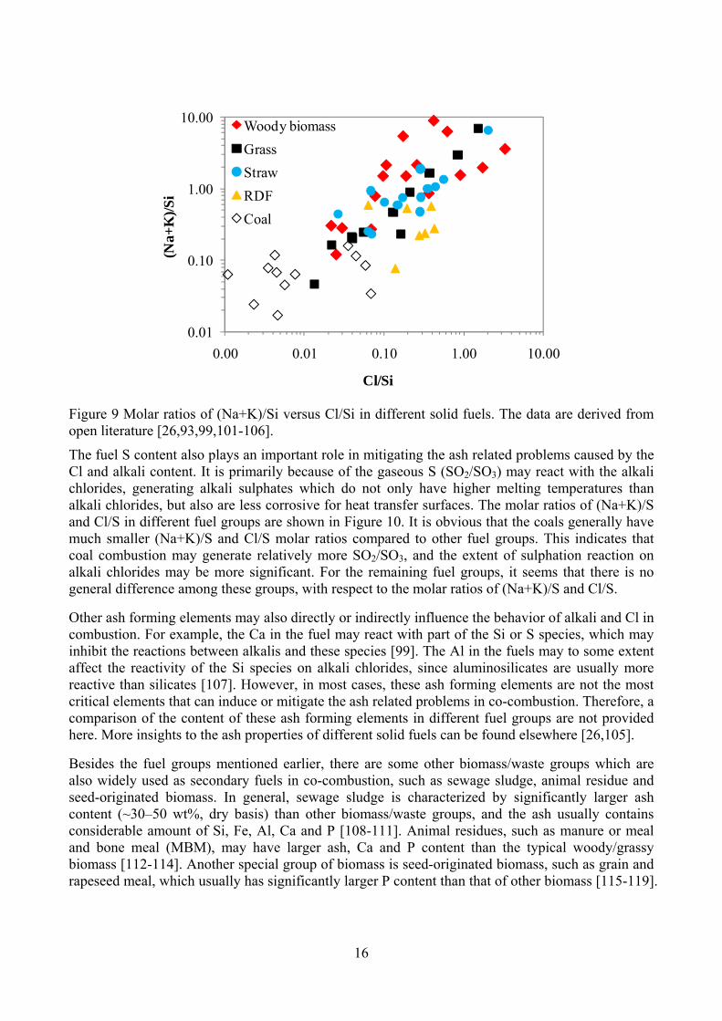
One of the major inorganic elements that may influence the behavior of alkali and Cl during combustion is Si. This is because some Si containing minerals in the fuel (such as kaolinite) may react with the gaseous alkali chlorides generated from combustion, and lead to the formation of high-melting temperature alkali aluminosilicates/silicates and gaseous HCl. The molar ratios of (Na+K)/Si and Cl/Si in different fuel groups are plotted in Figure 9. It shows that the molar ratios of (Na+K)/Si and Cl/Si in coals are generally much smaller than that of other fuel groups, indicating that coals may contain relatively more reactive Si species than other fuel groups, which may prevent the formation of alkali chlorides during combustion. For the remaining fuel groups, the variations of the molar ratios of (Na+K)/Si and Cl/Si are significant, and no general tendency can be observed.
0.0
1.0
2.0
3.0
4.0
5.0
0 10 20 30 40
Alk
ali (
wt%
db
.)
Ash (wt% db.)
Woody biomass
Grass
Straw
RDF
Coal
(a)
0.0
0.5
1.0
1.5
2.0
0 10 20 30 40
Ch
lori
ne
(wt%
db
.)
Ash (wt% db.)
Woody biomass
Grass
Straw
RDF
Coal
(b)
16
Figure 9 Molar ratios of (Na+K)/Si versus Cl/Si in different solid fuels. The data are derived from open literature [26,93,99,101-106].
The fuel S content also plays an important role in mitigating the ash related problems caused by the Cl and alkali content. It is primarily because of the gaseous S (SO2/SO3) may react with the alkali chlorides, generating alkali sulphates which do not only have higher melting temperatures than alkali chlorides, but also are less corrosive for heat transfer surfaces. The molar ratios of (Na+K)/S and Cl/S in different fuel groups are shown in Figure 10. It is obvious that the coals generally have much smaller (Na+K)/S and Cl/S molar ratios compared to other fuel groups. This indicates that coal combustion may generate relatively more SO2/SO3, and the extent of sulphation reaction on alkali chlorides may be more significant. For the remaining fuel groups, it seems that there is no general difference among these groups, with respect to the molar ratios of (Na+K)/S and Cl/S.
Other ash forming elements may also directly or indirectly influence the behavior of alkali and Cl in combustion. For example, the Ca in the fuel may react with part of the Si or S species, which may inhibit the reactions between alkalis and these species [99]. The Al in the fuels may to some extent affect the reactivity of the Si species on alkali chlorides, since aluminosilicates are usually more reactive than silicates [107]. However, in most cases, these ash forming elements are not the most critical elements that can induce or mitigate the ash related problems in co-combustion. Therefore, a comparison of the content of these ash forming elements in different fuel groups are not provided here. More insights to the ash properties of different solid fuels can be found elsewhere [26,105].
Besides the fuel groups mentioned earlier, there are some other biomass/waste groups which are also widely used as secondary fuels in co-combustion, such as sewage sludge, animal residue and seed-originated biomass. In general, sewage sludge is characterized by significantly larger ash content (~30–50 wt%, dry basis) than other biomass/waste groups, and the ash usually contains considerable amount of Si, Fe, Al, Ca and P [108-111]. Animal residues, such as manure or meal and bone meal (MBM), may have larger ash, Ca and P content than the typical woody/grassy biomass [112-114]. Another special group of biomass is seed-originated biomass, such as grain and rapeseed meal, which usually has significantly larger P content than that of other biomass [115-119].
0.01
0.10
1.00
10.00
0.00 0.01 0.10 1.00 10.00
(Na+
K)/
Si
Cl/Si
Woody biomass
Grass
Straw
RDF
Coal

17
Figure 10 Molar ratios of (Na+K)/S versus Cl/S in different solid fuels. The data are derived from open literature [26,93,99,101-106].
3.2 Association of ash forming elements
The concentration of the ash forming elements in the fuel is not the only factor that influences the ash behavior during combustion. An additional factor which can play an important role is the association of these elements. Although different classification methods may be used, the ash forming elements in solid fuels can be generally categorized as organic association (elements that are organically bound, ionically bound or water dissolvable) and mineral association (elements that exist as included or excluded minerals) [120,121]. The association of the ash forming elements may not only greatly affect the vaporization behavior of these elements during combustion but also influence their reactions.
A number of methods have been applied to evaluate the association of ash forming elements in coal, such as microscopy based techniques (e.g. CCSEM) and spectroscopy based techniques (e.g. XAFS and XRD) [122,123]. However, some of these techniques developed for coal may not be appropriate for biomass, since biomass is often characterized by a low degree of mineralization. A widely used method for identifying the association of ash forming elements in biomass/waste is the chemical fractionation method, which was initially developed for coal [124,125], and later adapted to biomass/waste [126,127]. The chemical fraction method is a sequential leaching method. According to the standardization proposed by Zevenhoven et al. [127,128], the fuel sample is leached successively by water, 1 M ammonium acetate and 1 M hydrochloric acid, and then the concentrations of ash forming elements in these solutions as well as in the residue are analyzed. The partitioning of the ash forming elements to different fractions can provide information about the occurrence mode of these elements. In general, it is considered that the easily soluble salts such as alkali chlorides and sulphates would appear in the water soluble fraction; the organically associated ions would be mostly present in the ammonium acetate solution; the acid solution would consist of acid-soluble salts or minerals like earth alkaline carbonates and sulphates; and the residues would be primarily comprised of mineral materials such silicates or aluminosilicates [127,129]. It has to be
0.01
0.10
1.00
10.00
0.00 0.01 0.10 1.00 10.00
(Na+
K)/
S
Cl/S
Woody biomass
Grass
Straw
RDF
Coal

18
mentioned that the interpretations to the chemical fractionation results are quite fuel/element specific, and there is no general agreed guidelines for quantifying the results [129]. Nevertheless, the chemical fractionation analysis is still considered to provide valuable information about the speciation of ash forming elements in different solid fuels, and the information is important for understanding the behavior of these elements during combustion [128].
Based on the chemical fractionation analysis [130-134], the association of some critical ash forming elements in different solid fuels is compared in Figure 11–Figure 13. In the figures, the fractions that are leached by water and ammonium acetate are summed together, since these fractions are considered to behave similarly during combustion (i.e. relatively easier to be released to gas phase). The remaining fractions, i.e. acid soluble fraction and residue fraction, are considered to be more difficult to be released during combustion.
Figure 11 Percentage of K and Na (%) that appears as H2O and NH4Ac (ammonium acetate) soluble in different solid fuels. The data are derived from open literature [130-135].
From Figure 11, it is seen that the majority of the K (60–100%) in biomass/waste is leachable by water and ammonium acetate, while this fraction in most coals is usually less than 10% (except for some low rank coals). This indicates that the association of K in biomass/waste may be quite different from that of coal. In live plants, such as wood and straw, the K may predominantly exist as mobile ions surrounded by water molecules, or present as organically associated K such as oxalates and oxygen-containing functional groups. When the plants are harvested and dried, part of the K ions may be converted to KOH, KCl and K2CO3, and the remaining may still be dissolved in water, depending on the extent of the drying process [136]. The K species mentioned above are mostly leachable by water and ammonium acetate. However, the K in coals may be mainly present as minerals, such as illite and muscovite [131,136-138], which are difficult to leach by water and ammonium acetate. However, for some low rank coals, such as lignite, a considerable fraction of K may exist as water and ammonium acetate soluble [135]. Compared to K, the fraction of water/ammonium acetate soluble Na in coals is larger (20–100%) and shows greater variations. This is presumable because a certain fraction of Na in coals is present as water soluble salts such as NaCl or organically associated [131,139]. For biomass/waste, the percentage of Na that is leachable by
0
20
40
60
80
100
0 20 40 60 80 100 120
K s
olu
ble
in
H2O
an
d N
H4A
c (%
)
Na soluble in H2O and NH4Ac(%)
Woody biomass Grass Straw RDF Coal

19
water and ammonium acetate varies significantly for different biomass/waste, and no general tendency is observable.
Figure 12 shows the percentage of Cl and Si that are present as water and ammonium acetate soluble in different solid fuels. It is seen that the Cl is almost fully soluble in water and ammonium acetate in different solid fuels. This may be explained by the association of Cl in these fuels. In coals, the Cl may exist as chloride anions in moisture, inorganic chlorides (such as NaCl and KCl), or organic chlorine compounds (such as covalently bonded Cl or Cl combined to organic complexes) [140]. For biomass, the majority of Cl may be associated with the nutrient cycle and the living portion of the biomass materials [140], in forms of free anions or loosely bound to exchange sites [141]. These Cl species are generally leachable by water and acetate solution. However, for some plastics materials, such as PVC, the Cl may not be soluble in water and acetate solution, but still can be released to gas phase during combustion [131]. This may explain the large fraction of insoluble (by water and acetate) Cl found in RDF in Figure 12. Besides, in some coals, the Cl may be associated with minerals such as sodalite (Na8(AlSIO4)6Cl2) [140], which may be a possible explanation for the insoluble Cl part. It has to be mentioned that there are some limitations in determining the partitioning of Cl through the chemical fractionation analysis [131,132]. For some low-Cl fuels, such as coal and wood, the concentration of Cl in the water or acetate solution may be below the detection limit of the analysis method, and the analysis uncertainties may be considerably high [129]. Besides, since it is not possible to determine the fuel-Cl that is leached by the HCl solution and the Cl content in the residue is often greatly influenced by the HCl leaching process, the reliability of the chemical fractionation method on Cl partitioning may not be evaluated through mass balance calculations. These limitations need to be considered when evaluating/utilizing the results from chemical fractionation analysis.
Figure 12 Percentage of Cl and Si (%) that appears as H2O and NH4Ac (ammonium acetate) soluble in different solid fuels. The data are derived from open literature [130-135].
In contrast to Cl, the Si in different solid fuels is mostly (>90%) not soluble by water and ammonium acetate, as shown in Figure 12. For coals, the Si may predominantly exist as minerals such as quartz, kaolinite and illite [137]. In biomass, the Si may be present as polymerized silicic
0
20
40
60
80
100
0 20 40 60 80 100
Cl s
olu
ble
in
H2O
an
d N
H4A
c (%
)
Si soluble in H2O and NH4Ac(%)
Woody biomass Grass Straw RDF Coal

20
acid, which is an amorphous mineral of silica with varying amount of crystal water (SiO2·nH2O) [129,141]. In addition, a certain fraction of Si in biomass may be from the soil contaminations during the collection process, which may exist as quartz and clay materials [142].
Figure 13 Percentage of Ca and S (%) that appears as H2O and NH4Ac (ammonium acetate) soluble in different solid fuels. The data are derived from open literature [130-135].
Figure 13 shows the percentage of S and Ca that is present as water and ammonium acetate soluble in different solid fuels. It appears that coals generally contain less water and acetate soluble S than that of grasses and straws, indicating that the association of S may be different in these fuels. In coals, the S may be mainly present as minerals (mainly as pyrite but also as other sulfides and sulphates) or organically associated with aliphatic, aromatic, and heterocyclic structures. The sulphide minerals, which are usually the dominant inorganic S components in coals, are largely insoluble in water or ammonium acetate solutions. In addition, the organically associated S in coals is also found to have a low solubility in water or other organic solutions [143]. This may explain the relatively small fraction of the water and ammonium acetate soluble S found in coals. On the other hand, the S in biomass may be mainly present as inorganic sulphates or organically associated S with aliphatic nature such as in proteins, sulphate ester and sulphur lipids [141,142]. The sulphates may be easily leachable by the water and ammonium acetate solution, whereas the organically associated S may be difficult to be dissolved in these solutions [129]. For annual crops such as straw and grass, a large fraction (>50%) of S in these biomass may be present as sulphates, as indicated by the S release characteristics during the pyrolysis of these biomass [144]. However, for woody biomass, the majority of S may be organically associated, thus the water and ammonium acetate soluble fraction is usually only around 25% [129]. Compared to S, the percentage of Ca that is present as water and ammonium acetate soluble varies significantly for different fuels, and no tendency can be seen for different fuel groups. In biomass, the Ca that is leachable by water and ammonium acetate may be mainly ionic Ca (acting as counter ions for organic and inorganic anions such as malate and nitrate), Ca oxalate and other calcium salts of carboxylic acids [131,141]. In coals, the majority of Ca that is water and ammonium acetate leachable may be present as carboxylic groups and carbonate [131].
0
20
40
60
80
100
0 20 40 60 80 100
Ca
solu
ble
in
H2O
an
d N
H4A
c (%
)
S soluble in H2O and NH4Ac(%)
Woody biomass Grass Straw RDF Coal

21
3.3 General ash formation mechanism
The ash formation mechanism in pulverized fuel combustion has been well-established [121,139,145-151]. As shown in Figure 14, the ash particles generated during pulverized fuel combustion primarily originate from excluded minerals, included minerals and organically associated ash forming species in the fuel particles. When the fuel particles are combusted, a fraction of the included minerals and organically associated ash forming elements may be released to gas phase, either through a direct release mechanism or a mechanism involving reducing reactions. After that, the vaporized inorganic elements may nucleate to ultrafine particles, condense on the surface of the existing particles, or chemically react with other particles. The partitioning of the vaporized inorganic elements may be dependent on the fuel properties and the combustion conditions such as cooling rate and particle density in the flue gas [121]. The ultrafine particles generated from the nucleation of inorganic vapors may aggregate/coalesce with themselves to form larger particles, which are usually an important source of submicron ash particles formed during pulverized fuel combustion. On the other hand, the ultrafine particles may also attach to the surface of the existing large fly ash particles, which may therefore partition to the supermicron ash particles.
Figure 14 Ash formation pathways during solid fuel combustion, adapted from [121] .
In addition to the fraction that is vaporized, the remaining minerals and organically associated ash forming elements in the fuel particles may undergo fragmentation, melting and coalescence during the fuel conversion process. The majority of these ash forming elements may result in the formation of supermicron ash particles, while a small fraction may contribute to the formation of submicron

22
ash particles, probably via the fragmentation mechanism. The excluded minerals may also experience melting and a small extent of fragmentation/coalescence (depending on the mineral type), and may be converted mainly to supermicron ash particles during the combustion process.
Figure 14 shows that ash formation during solid fuel combustion is a complicated physical and chemical process, and may be affected by a number of factors. In the following sections, the release and transform of ash forming species during solid fuel combustion will be described in detail, with a special focus on the possible interactions during different fuels.
3.4 Release of ash forming elements
As mentioned earlier, the release of ash forming elements during pulverized fuel combustion may follow a direct release mechanism or a mechanism involving reducing reactions. The direct release mechanism may involve the release of organically associated elements during devolatilization or char oxidation, and the direct vaporization of some volatile inorganic species, such as NaCl and KCl. The reducing mechanism is usually applied for the species having low vapor pressure during combustion, such as SiO2 and CaO. With the reducing environment generated by devolatilization or char oxidation, these oxides may be reduced to more volatile sub oxides or elemental vapor, which would facilitate the vaporization of these elements [149,150,152,153].
The vaporization of ash forming elements during pulverized coal combustion has been studied extensively through experiments and modeling [152,154-161]. These studies generally suggest that the vaporization of refractory oxides (such as SiO2, Al2O3, CaO and MgO) during pulverized coal combustion is mainly achieved through the reducing mechanism described by the following global reaction:
1 2( ) ( )n nMO c CO MO v CO (1.4)
where MOn and MOn-1 refer to the refractory oxide and the corresponding volatile suboxide or metal vapor, respectively. In the modeling approach of Quann and Sarofim [152], it is assumed that the equation above is in equilibrium on the surface of mineral inclusions in the char particle and the CO2 is only produced from the reaction above (i.e. the vapor pressure of MOn-1 and CO2 is the same). With these assumptions, the vapor pressure of MOn-1 on the surface of the mineral inclusions can be predicted from the partial pressure of CO and the equilibrium constant of the reaction. By taking into account the internal and external diffusion of the vaporized MOn-1 in the char particle as well as the interactions between different mineral inclusions, the vaporization of MOn during pulverized coal combustion has been reasonably well modeled [152]. However, as pointed out later by some following work [156,157,160], there are some limitations in the model developed by Quann and Sarofim [152]. In their model, the vapor pressure of CO2 on the mineral inclusion surface may be underestimated, which may result in an over estimation of the vapor pressure of MOn-1 [156,157]. Besides, the model also neglects the enlargement of the pores and the corresponding increase in effective diffusivity near the surface of burning char particle, which may overestimate the diffusion resistance to vaporization [160].
In addition to the reducing mechanism mentioned above, direct release mechanism may also play a role, particularly for low rank coals, such as lignites, which contain substantial amount of alkali and earth alkali metals. A typical example is the release of Na during the combustion of low rank coals [139,153,162,163]. The Na in low-rank coals may be primarily associated with organic matter or exist as halide (NaCl) [139,153]. During combustion this organically associated Na and halide may

23
be vaporized to gas phase as metal, oxide or chloride, due to the high vapor pressure of these species [153]. For lignite, above 40% of the Na in the fuel was found to be vaporized at a furnace temperature of 1477 oC and at 20% O2 condition [153]. A significant percentage (~18%) of the Mg was also found to be vaporized at the same experimental condition, consistent with the large amount of organically associated Mg in the low rank coal [152]. However, the vaporization of organically associated Mg may still follow a reducing mechanism, but with significantly reduced diffusion resistances compared to mineral inclusions [152].
The vaporization of ash forming elements during pulverized coal combustion may be influenced by various factors. In general, with higher combustion temperature, the vaporization of ash forming elements through the reducing mechanism can be promoted [152,160], whereas the vaporization of alkali metals (such as Na) may be reduced by an increased reaction rate between the vaporized alkali metals and silicates/aluminosilicates in the coal [153,163]. The particle size of coal may affect the vaporization of refractory oxides as well. With decreasing particle size, the vaporization of refractory oxides through the reducing mechanism may be promoted, presumably related to distribution of mineral inclusions in the particle [152]. The gas environment may also play an important role on the vaporization of ash forming elements. According to the model developed in [152], it is obvious that a more reducing environment is favorable for the vaporization of refractory oxides, when the combustion temperature is fixed. The association of ash forming elements also greatly influences their vaporization behavior. The organically associated elements are usually easier vaporized compared to mineral associations [152,153]. On the other hand, the distribution between excluded and included minerals may also have some impact. A positive correlation may be found between the vaporization of refractory oxides and their association as included minerals [152,164]. This is likely because included minerals may experience higher combustion temperature and more reducing conditions that of excluded minerals.
It should be noted that in the majority of the studies mentioned ealier, the vaporization of ash forming elements is quantified by sampling fine particles after combustion [152,154-161]. Therefore, the obtained vaporization results are naturally interfered by the secondary reactions between the vaporized species and other ash forming species. Such influence is particularly pronounced for the vaporized alkali species [153,163]. These possible secondary reactions will be discussed in detail in the following section.
Compared to pulverized coal combustion, the vaporization of ash forming elements during pulverized biomass/waste combustion has been less investigated and literature on this subject is scarce. Recently, Shah et al. has attempted to quantify the release of inorganic elements during pulverized biomass combustion, by performing experiments in a lab-scale combustion simulator with high initial heating rate (105 oC/S) and temperature (1450–1600 oC) [165,166]. The release of inorganic elements is quantified by assuming the elements present in vapor phase and in the submicron aerosols are vaporized during the combustion. The results obtained after complete combustion (with a residence time of about 1300 ms) are shown in Figure 15. It can be seen that the release of S and Cl is fairly complete (>80%) during the combustion of pulverized biomass or coal, and no significant deviation is observed for different biomass or coal. However, the release behavior of alkali metals is considerably different for coals and biomass. For K, it appears that above 90% of the K in woody biomass has been released to gas phase, which is only slightly higher than that of straw (~80%) but significantly greater than that of coals (<20%). Such difference may be primarily related to the different associations of K in biomass and coal, as illustrated in Figure 11. In addition, the secondary reactions between the vaporized K and the mineral matters in the fuels may also influence the K release obtained in the experiments. Compared to the K release, the

24
deviations between the Na release in biomass and coal seem to be less significant, which may be explained by the variety of the Na association in coals, as shown in Figure 11. Compared to alkali metals, the release of Mg and Ca is generally less pronounced during pulverized biomass/coal combustion. However, for woody biomass, a considerable fraction of the Mg and Ca (20-50%) may still be released to gas phase during combustion. For Al and Si, the release is generally found to be negligible for different fuels [165,166].
Figure 15 Release of ash forming elements under pulverized fuel combustion condition. The data are derived from [165,166], with a residence time of about 1300 ms (almost complete combustion). The woody biomass refers to bark, wood chips and waste wood, and the coals are a UK and a Polish coal.
The release of ash forming elements during biomass/waste combustion has been better characterized at grate-firing conditions [128,141,142,144,167-173]. Although the results may not be directly transferred to pulverized fuel combustion conditions, these studies can provide valuable insights to the release mechanisms of these elements, and the guidelines for the important parameters that may influence the release.
Figure 16 shows the release of Cl at a function of temperature during the combustion of different biomass groups such as straw and woody biomass as well as some waste materials such as fiber board and PVC [142,168,172]. The results presented are obtained from the same laboratory-scale reactor and the experimental conditions are similar for different fuels. Thus the deviations shown in the figure mainly result from the different fuel characteristics. From the figure, it is seen that approximately 20-60% of the Cl is released from straw at a combustion temperature of 500 oC, and
0
20
40
60
80
100
0 20 40 60 80 100 120
S r
elea
se (
%)
Cl release (%)
Woody biomass Straw Coal
0
20
40
60
80
100
0 20 40 60 80 100 120
Na
rele
ase
(%)
K release (%)
Woody biomass Straw Coal
0
20
40
60
80
100
0 20 40 60 80 100 120
Mg
rele
ase
(%)
Ca release (%)
Woody biomass Straw Coal
0
20
40
60
80
100
0 20 40 60 80 100 120
Al r
elea
se (
%)
Si release (%)
Woody biomass Straw Coal

25
the remaining Cl is mostly released in a temperature range of 500–800 oC. For woody biomass, the release of Cl (>80%) seems to be greater than that of straw at 500 oC. However, the quantification of Cl release during wood combustion is usually rather difficult to perform due to the low Cl content in most of woody biomass, thereby only very limited woody biomass data are shown in Figure 16. Different from the woody biomass and straw, the Cl in the fiber board/PVC is almost completely released at a combustion temperature of 500 oC.
Figure 16 Release of Cl at different temperatures under grate-firing conditions [142,168,172].
The release of Cl at combustion temperature below 500 oC is primarily due to the vaporization of HCl (g) [141,142,167,168,172]. Since the majority of Cl in straw or woody biomass is leachable by water [131,174], it is suggested that the Cl in straw or woody biomass may predominantly exist as KCl. Thus a major mechanism for the release of Cl at temperatures below 500 oC is considered to be the reaction between KCl and the carboxylic groups of the fuel, which could result in the formation of HCl (g) and char-K [141,142,167,168,172]. The presence of such a reaction is supported by the considerable Cl release observed at 400 oC, when pure KCl is mixed with wood or cellulose [175]. However, the extent of the reaction may be confined by the available proton-donating sites in the char/fuel. In general, a negative correlation is found between the Cl release at 500 oC and the Cl content in straw [142]. This indicates that for a fuel with high Cl content compared to the number of proton-donating sites, the conversion of KCl to HCl (g) may be relatively low. This may be an explanation to the observed deviations of the Cl release at 500 oC in Figure 16, especially the general difference between the low-Cl woody biomass and the high-Cl straw. On the other hand, a small fraction of Cl in biomass may be combined to the organic structures. The Cl may be released directly during the devolatilization, either in tar or decomposed to HCl (g) [142,173]. A typical example of the release of the organically associated Cl is the combustion of PVC. As shown in Figure 16, almost all of the Cl in PVC is released to gas phase at 500 oC, which is because the organically bound Cl has been decomposed to HCl (g) during devolatilization in a temperature range of ~200–370oC [29-32].
0
20
40
60
80
100
400 600 800 1000 1200
Cl r
elea
se (
%)
Temperature (oC)
Woody biomass Straw Fiber board PVC

26
The second stage of Cl release during biomass combustion, which mainly happens in the temperature range of 500–800 oC, is mostly a result of KCl or NaCl vaporization [141,142,167,168,172]. The vaporization of KCl and NaCl during biomass combustion has been detected directly by a molecular beam mass spectrometer system [174]. It should be noted that at lower temperatures, such as 650 oC, the vaporization of KCl may be limited by the diffusion resistances, particularly in the reactor used in [142,168,172]. However, at higher temperatures, such as 800 oC, the diffusion resistances would become negligible, due to the high vapor pressure of KCl [167].
Figure 17 Release of S at different temperatures under grate-firing conditions [142,168,172].
Figure 17 shows the release of S during the combustion of biomass and waste materials at different temperature [142,168,172]. For straw, it appears that approximately 20–60% of the S is released at 500 oC. With increasing temperature, the release of S increases progressively and for most of straw the S is almost completely released at a combustion temperature of 1150 oC. Compared to straw, the release of S during woody biomass combustion is generally greater in the temperature range of 500–1000 oC. At 500 oC, the S release for woody biomass is mostly in the range 60–80%, and the release is not significantly increased up to 850 oC. In the temperature range of 850–1150 oC, a considerable increase of the S release is observed for woody biomass, and an almost complete release is achieved at 1150 oC. Different from biomass, the S release during PVC combustion seems to be completed already at 500 oC. For fiber board, the characteristics of the S release are quite similar to that of straw.
The release of S during biomass combustion at temperatures below 500 oC is mainly attributed to the release of organically associated S during the devolatilization process [141,142,167,168]. This is supported by the fact that the S release obtained during straw pyrolysis and combustion is similar at 500 oC [142]. In addition, the S release obtained during woody biomass combustion at 500 oC seems to be correlated well with the organic S fraction derived from the chemical fractionation analysis [168]. Thus the deviations of the released S at 500 oC for different woody biomass and straw may be explained by the different S associations in these fuels.
0
20
40
60
80
100
400 600 800 1000 1200
S r
elea
se (
%)
Temperature (oC)
Woody biomass Straw Fiber board PVC

27
Figure 18 Release of K at different temperatures under grate-firing conditions [142,168,172].
The release of S at higher temperatures may follow more complicated mechanisms. For straw with relatively high Si content, the reaction between K2SO4 and silicates may contribute to the S release at temperatures above 700–800 oC, through the formation of K-silicates and SO2 (g). The contribution of this reaction to the S release may be greatly affected by the molar ratio of K/Si in the fuel [142]. Besides, the Cl in the fuel may also indirectly affect the S release at temperatures above 500 oC. With a greater Cl/K molar ratio in the fuel, the S release in the temperature range of 700–950 oC is found to be increased, presumably due to the fact that part of the alkali sulphate is converted to alkali chloride and SO2 [142]. On the other hand, the direct vaporization or decomposition of sulphate (such as K2SO4 or CaSO4) may also constitute an important S release mechanism at high temperatures, particularly for fuels with relatively low Si and Cl content (such as woody biomass) [142,168]. However, in most cases, the contribution of this mechanism to S release is insignificant at temperatures below 1000 oC, due to the low vapor pressure and high thermal stability of the sulphates. At higher temperatures, this mechanism becomes increasingly important, and contributes greatly to the almost complete S release at about 1150 oC.
The release of K during the combustion of biomass and waste materials at different temperature is shown in Figure 18. It is seen that for the majority of the woody biomass and straw, the release of K is insignificant at temperatures below 600 oC. Most of the K in woody biomass and straw is released in the temperature interval of 700–1150oC. At 1150 oC, the release of K from woody biomass and straw is found to be in a range of 60–90%. In general, large deviations are observed for different biomass with respect to the K release and no general tendency is seen between straw and woody biomass. Compared to biomass, the K release in PVC seems to be greater and occurring at lower temperatures. For the fiber board, a general low K release is seen up to 1150 oC, which may be related to the high Ti content in the fuel [168].
Several different mechanisms may contribute to the K release during woody biomass and straw combustion. At temperatures below 500 oC, although the release of K is generally insignificant and
-20
0
20
40
60
80
100
400 600 800 1000 1200
K r
elea
se (
%)
Temperature (oC)
Woody biomass Straw Fiber board PVC

28
may be greatly affected by the experimental uncertainties, a small fraction of K (0–10%) may still be released due to the decomposition of organically associated K [142,168]. In the temperature range of 500–800 oC, the release of K for Cl rich biomass is mainly via the vaporization of KCl, which is supported by the fact that the molar ratio of the released K/Cl is about 1 [142]. The release of K through KCl vaporization may be promoted by increasing the molar ratio of Cl/K in the fuel [142]. On the other hand, for biomass with relatively low Cl content such as wood, the contribution of KCl vaporization to K release is rather limited. Thus the major K release mechanism for these biomass during 500–800 oC is considered to be the decomposition of the K associated with the char matrix or the decomposition of K2CO3 [167,168]. At temperatures above 800 oC, irrespective of the original Cl content in the fuel, a major K release mechanism is considered to the vaporization of K or KOH originated from the decomposition of K2CO3 or the char associated K. In a dry environment, the decomposition of K2CO3 may produce elemental K, which may be vaporized and subsequently react with other gaseous species. With the presence of water vapor, the K2CO3 may be decomposed to KOH (g), which may considerably promote the release of K [167,169]. However, the K release during biomass combustion may be adversely affected by the reaction between the vaporized K and the silicates in the ash. The extent of such reaction is closely related to the availability of reactive silicates in the fuel and the contacting and reaction rate between the silicates and vaporized K. At higher combustion temperatures, the vaporization rate of K may greatly exceed the reaction rate of K and silicates, which could be an explanation to the increasing K release observed in the temperature range of 900–1150 oC. On the other hand, the presence of other inorganic elements, such as Ca and Mg, may compete with K for reacting with silicates, thus may promote the release of K to some extent [167-169].
In addition to S, Cl and K, the release of Na is also found to be significant during biomass/waste combustion at grate-firing conditions [168,171,172]. However, the Na content in most biomass is considerably lower than that of K. Thus a detailed quantification of Na release is difficult to achieve via experiments. Besides, the mechanisms for Na release during biomass combustion are in most cases analogous to that of K. Therefore, a detailed discussion on the Na release is not performed here, but can be found elsewhere [168,172]. Besides the elements mentioned above, the release of other elements such as Si, Al, Ca and Mg during biomass/waste combustion are generally found to be negligible [142,168,172]. An additional element which may exhibit high volatility during biomass/waste combustion is phosphorus. However, detailed investigations on the release characteristics of phosphorus are scarce in literature.
3.5 Interactions in ash chemistry
During pulverized fuel combustion, complicated interactions may occur among the ash forming elements, which cannot only alter the chemical form of these elements in the flue gas but also greatly affect the partitioning of these elements into fly ash of different particle size. These interactions are mostly achieved through gas-gas reactions of the vaporized ash forming elements, or the gas-solid reactions between the solid ash particles and the vaporized ash forming elements. The major vaporized ash forming elements during pulverized coal combustion can be categorized as S, Cl, refractory metals (such as Si, Al, Fe, Ca and Mg), and alkali metals (such as K and Na). Since the refractory metals are mostly vaporized through a reducing mechanism, these metals are usually quickly re-oxidized at the vicinity of a burning char particle and nucleate to small solid/liquid ash particles [155]. Thus the major vaporized ash forming elements, which may have relatively long residence time during pulverized coal combustion, are S, Cl and alkali metals. Since these elements are also the major ash forming elements released from biomass or waste combustion and are the most critical elements for ash deposition and corrosion in pulverized fuel combustion, the possible

29
reactions of vaporized alkali metals, S and Cl are mainly emphasized in this section.
3.5.1 Reactions between vaporized alkali metals and kaolinite
The vaporized alkali metals during pulverized coal combustion usually exist as alkali hydroxides or alkali chlorides. These alkali species may react with the coal minerals at high combustion temperature, resulting in the formation of alkali aluminosilicates/silicates as well as gaseous HCl/H2O. A typical example is the reaction between vaporized Na species and kaolinite, which has been the subject of extensive research [146,163,176-184]. At combustion temperatures and particle residence times similar to pulverized coal combustion, the kaolinite (Al2O3·2SiO2·2H2O) particles can be readily converted to metakaolinite (Al2O3·2SiO2), however further conversion to mullite (3Al2O3·2SiO2) may be greatly confined by the residence time. The formed metakaolinite can react with the vaporized sodium species (such as NaOH or NaCl), and generate sodium aluminosilicates such as nephelite and carnegieite (both with a chemical form of Na2O·Al2O3·2SiO2). The transformation from kaolinite to metakaolinite and then to sodium aluminosilicates may cause some free silica to be released. Thus some sodium silicates may be formed initially along with the sodium aluminosilicates. As the reaction proceeds, the basic metakaolinite crystal structure may break down into silicates and aluminates, allowing accommodating more vaporized sodium species than the predicted product (Na2O·Al2O3·2SiO2). It should be noted that the initial generated sodium aluminosilicates can form an eutectic with the remaining metakaolinite, and cause melting. This melt can enhance the reaction rate between the kaolinite and vaporized sodium by breaking apart and opening up the tightly parked metakaolinite crystal structure, and by inducing a surface renewal to allow access to the unutilized metakaolinite buried under the unexposed platelet layers [180]. On the other hand, as the reaction progresses, the entire kaolinite particle may transform to a catastrophic melt, which can deactivate the reaction by closing the pores [176].
The reactions between the kaolinite and vaporized sodium are influenced by different factors such as temperature, particle size, molar ratio between the sodium and kaolinite, residence time, and gas environment [163,179,180]. The optimum temperature window for the reaction between the vaporized sodium and kaolinite has been proposed to be 900–1100 oC [179], since a higher temperature may result in a significant melt-induced deactivation, particularly when the molar ratio of the vaporized sodium and kaolinite is high [180,185]. The particle size of kaolinite may also impact the reaction rate. Under the same experimental conditions, the conversion of submicron kaolinite particles is found to be at least 6 times greater than the particles around 9 µm [179]. The results suggest that the reaction between vaporized sodium and kaolinite particles in the range of 3–9 µm are controlled by pore diffusion, whereas the smaller particles (0.65–3µm) are in a transition of pore diffusion and reaction control [179]. A lower molar ratio between the vaporized sodium and kaolinite is usually preferable in order to completely capture the sodium, but the effect becomes less significant when the molar ratio is already below 0.5 [180]. The presence of gaseous Cl and S may inhibit the reaction between the vaporized Na and kaolinite [163,179].With the presence of gaseous Cl, part of the vaporized Na may be converted to NaCl [162], which may react much slower with kaolinite than that of NaOH [163]. On the other hand, the presence of gaseous S may result in the formation of sodium sulphate, which may condense at higher temperature and reduce the residence time for the gas–solid reaction [179].
Several mathematical models have been proposed to simulate the reaction between kaolinite and vaporized sodium [163,177,179,180,182]. Punjak et al. have developed a model which describes the simultaneous diffusion and reaction of sodium vapor in a porous kaolinite particle [182,183]. The model fits well with the experimental data obtained at 800 oC, but it did not take into account the

30
possible deactivation at higher temperatures [182,183]. Recently, Gale and Wendt have proposed a model which utilizes two global reactions to describe the reaction between kaolinite and sodium vapor as well as the deactivation at high temperature [180]. The simulation results are in good agreement with the experimental results, and the feature of the high temperature deactivation has been well-characterized by using the two-step approach [180].
The reactions between the vaporized K species and kaolinite are generally analogous to that of kaolinite and vaporized Na species [107,184,186,187]. A direct comparison indicated that the adsorption rate of kaolinite on NaCl and KCl was similar at 850 oC [184]. The experiments carried out by Tran et al. show that kaolinite can capture vaporized potassium (such as KCl and KOH) both by chemical reaction and physical adsorption at 850 oC [186]. In the temperature range of 750–950 oC, the capture efficiency of kaolinite on KCl is found to decrease with increasing temperature, which is explained as an increased desorption rate of KCl at higher temperatures, since the kaolinite sintering is insignificant at the experimental temperature range. The influence of different K species on the capture efficiency is also investigated, showing that the K capture efficiency is similar for KCl and KOH but significantly lower for K2SO4 [186].
Zheng et al. have studied the reactions between kaolinite and vaporized potassium at a temperature range of 900–1500 oC [107]. They reveal that in the temperature range of 900–1300 oC, the amount of potassium captured by kaolinite decreases with increasing temperature, which is explained as a higher degree of sintering in the kaolinite pellet with increasing temperature. However, at temperatures above 1300 oC, the amount of potassium captured by kaolinite starts to increase with increasing temperature. This is presumably because of the appearance of a molten phase in the kaolinite pellet at temperatures above 1300 oC, which could facility the transportation of KCl and increase the reaction rate. A mathematical model similar to that in [182,183] is developed to describe the diffusion and reaction between vaporized KCl and kaolinite pellet at 900 oC [107]. However, this model neglects the effect of sintering and melting, which limits its application at higher temperatures.
3.5.2 Reactions between vaporized alkali metals and other minerals
In addition to kaolinite, other minerals in coal may react with the vaporized alkali metals. Punjak et al. have compared the capture efficiency of kaolinite, emathlite and bauxite on the vaporized Na at 800 oC, showing that all of these minerals could capture the vaporized Na through chemical reactions [182,183]. In comparison with kaolinite, bauxite shows a higher initial capture rate and a lower ultimate capture capability (mass basis). However, the capturing of vaporized Na by bauxite is partly attributed to physical adsorption, which is different from the other two minerals where chemical reaction is dominated. The initial capture rate of emathlite is similar to that of kaolinite, while the capture capability of emathlite is close to that of bauxite. XRD (X-ray diffraction) analysis suggests that the formation of nephelite, carnegieite and glassy silicates may be responsible for the sodium capture by bauxite, whereas the formation of abite (Na2O·Al2O3·6SiO2) may account for the sodium captured by emathlite [182,183].
Silica (SiO2) is able to react with the vaporized sodium or potassium, although the reaction rate is usually much lower than that of kaolinite [107,163]. A direct comparison of the reaction rate of kaolinite and SiO2 under conditions similar to pulverized coal combustion indicates that the reaction rate of NaCl and kaolinite is 5–8 times higher than that of NaCl and silica [163]. A similar tendency is observed in fixed-bed experiments [107], showing that much less vaporized K is captured by silica compared to kaolinite and the capture efficiency of silica is almost not influenced by the

31
exposure temperature in the range of 900–1500 oC.
There are other mineral matters that could react with the vaporized alkali species. Kyi et al. have tested the reactions between sodium species (NaCl, NaOH and Na2SO4) and minerals such as kaolinite, bentonite, diatomite, miclay, pumice and pyrophyliite at 1000 oC and 1200 oC, showing that these Si and Al containing minerals generally exhibit a high reactivity that is comparable to kaolinite [188]. Mullite (3Al2O3·2SiO2) is usually considered to be an inert material towards vaporized alkali species. However, experimental results in a fixed bed reactor indicated that reaction starts to take place between mullite and vaporized potassium at temperatures above 1300 oC, possibly related to the formation of a molten phase inside the mullite pellet which reduces the transportation limitations [107]. Alumina (Al2O3) is found to be an effective sorbent to capture vaporized alkali species at moderate temperatures (e.g. <1000 oC). However, the alkali species captured by alumina is primarily achieved by physical adsorption, rather than chemical reactions [107,189]. Besides Si or Al based minerals, calcium phosphates, such as Ca(PO3)2, could also react with K species (such as K2CO3 and KCl) at 900–1000 oC through the formation of (K2O)k·(CaO)l·(P2O5)m structures, but such reactions may be greatly influenced by the temperature and the applied Ca/P molar ratio [169].
Direct study on the reactions between the vaporized potassium and coal ash has been carried out [107], showing that a Columbia bituminous coal (COPRIB) ash exhibits a capture behavior that is similar to kaolinite, both with respect to the capture efficiency on the vaporized potassium and its dependence on the exposure temperature. The capture efficiency of the COPRIB ash decreases with increasing temperature in the range of 900–1200 oC, but it increases significantly when the temperature becomes 1300 oC. The similarity between the capture efficiency of COPRIB ash and kaolinite is considered to be related to their similar Al and Si content. On the other hand, the lignite ash exhibits a much lower capture efficiency than the COPRIB ash, which is possibly related to the relatively small Si and Al content in the lignite ash. In addition, the lignite ash contains relatively large content of Ca and Mg, which may compete with K to react with the alumina and silica [107]. The competition between Ca and K on reacting with silica is further demonstrated through fixed bed experiments, showing that less K is captured by silica with the dosage of Ca [169]. The influence of coal ash properties on reaction with alkali species has been further studied through co-firing different coals with chlorine rich biomass [134], showing that the coal with a larger Al and Si content and a smaller K content reacts more easily with the gaseous alkali chlorides. CCSEM analysis of the fly ash from lignite combustion shows that the majority of the Na is combined to Al and Si (rather than Si alone), suggesting that the aluminosilicates are the preferred scavengers during coal combustion [178]. This conclusion is in agreement with experimental results obtained from different coal ashes [107,134], and the tendency indicated by global equilibrium calculations [96].
When the vaporized potassium and sodium are presented in the flue gas at the same time, they may interact with each other in reacting with minerals. The capture rates of an Al and Si based sorbent on vaporized KCl, NaCl and their mixture have been compared in fixed-bed experiments at 800 oC [190]. It is shown that the sorbent could capture KCl much faster than NaCl. For the mixture of NaCl and KCl, the observed capture rate is lower than the summation from pure components, indicating that the capturing of KCl by the sorbent may be inhibited by the presence of NaCl and the overall capture rate becomes similar to that of NaCl [190]. On the other hand, when a sorbent containing potassium (emathlite) is exposed to NaCl vapor at 800 oC, the potassium content in the sorbent is found to be decreased, indicating that a significant amount of potassium is released to the gas phase with the presence of NaCl vapor [183]. This tendency is supported by coal combustion

32
experiments under suspension-firing conditions [146], showing that the vaporization of potassium is not closely related to the association of potassium and the amount of silicates in the coal, but rather exhibiting a positive correlation with the vaporization of sodium. This indicates that that vaporized sodium may be able to displace some mineral bound potassium and facilitate its vaporization to gas phase [146].
3.5.3 Reactions between alkali metals and gaseous sulphur
During pulverized fuel combustion, significant interactions can occur between the vaporized alkali species and the gaseous sulphur such as SO2/SO3. The reactions between the vaporized alkalis (such as alkali chlorides) and the gaseous sulphur could potentially minimize the risk of ash deposition and corrosion in pulverized fuel-fired boiler, since alkali sulphates usually have much higher melting temperature and are less corrosive than alkali chlorides. The sulphation reactions of alkali species have been studied both through experiments and detailed kinetic modeling [191-199]. According to the detailed gas phase mechanism proposed by Hindiyarti et al. [194], the formation of K2SO4 at 1100 oC may follow the reaction pathways shown in Figure 19. It can be seen that the sulphation of KCl to K2SO4 may proceed with and without the presence of SO3/OH radical as an intermediate. At low temperatures (e.g.< 900 oC), the pathway involving the formation of KHSO3 is considered to be the major pathway, with the reaction from KHSO3 to KHSO4 being the rate-limiting step. However, at higher temperatures (e.g. > 1100 oC), the other pathways may also become important for K2SO4 formation, probably related to an increased generation of radicals at these temperatures. The mechanism proposed by Hindiyarti et al. [194] is found to be consistent with several experimental results [63,173,191], although further experiments in a rigorously homogeneous system are still needed for obtaining more insights into the mechanism [194].
Figure 19 Pathway diagram for potassium transformation at 1100 oC (under the conditions of Iisa et al. [191]) [194].
In addition to the homogeneous mechanism, the formation of alkali sulphates may also follow a heterogeneous mechanism involving the condensation of alkali containing species (such as alkali chlorides or hydroxides) on a surface and the subsequent sulphation in liquid or solid phase. According to the experimental and modeling studies carried out by Steinberg and Schofield [195,200-202], the formation of Na2SO4 (g) under fuel lean-flame conditions is considered to be kinetically limited through an analysis of the detailed reaction mechanism. Therefore they suggest that the heterogeneous sulphation mechanism is responsible for the formation of Na2SO4 at these conditions. This hypothesis is supported by the Na2SO4 formation rate obtained on a deposition probe, which is proportional to the total sodium content in the flame, but is independent of the fuel

33
type, equivalence ratio, flame temperature and sulphur concentration [195]. The heterogeneous sulphation of alkali chlorides has been studied directly through fixed-bed experiments in a temperature range of 400–850 oC [203,204]. It is revealed that the sulphation rate of the solid NaCl is very slow at temperatures below 600 oC, with only 0.5–1.1% of the NaCl being converted to Na2SO4 in 3 h. At these temperatures, the rate-limiting step is considered to be the adsorption of SO2 on the NaCl surface [203]. One the other hand, the sulphation rate of KCl or NaCl is increased considerably at temperatures above 650 oC, which is probably caused by a change in the reaction mode from a gas-solid to a gas-liquid and/or a gas phase reactions [204]. However, even at 850 oC, a quite large residence time (~hours) is needed in order to fully convert the alkali chlorides to sulphates [204].
The sulphation of KCl particles has been studied by Iisa et al. in a laminar entrained-flow reactor at 900–1100 oC, with the residence times of 0.2–1.2 s [191]. The results reveal that up to 100% conversion can be achieved for the vaporized KCl in the reactor, whereas only about 0.5–2% conversion is obtained for the melted KCl. This suggests that at residence times similar to pulverized fuel combustion condition, the homogeneous sulphation rate would be significantly higher than that of heterogeneous sulphation [191]. The importance of the the homogeneous sulphation mechanism over heterogeneous mechanism at entrained flow conditions is further supported by studying aerosol formation through laboratory-scale experiments and modeling [205,206]. The significant increase of the aerosol number concentration observed by adding SO2 to NaCl and KCl vapor indicate that the alkali sulphates result from the homogeneous sulphation of the vaporized alkali chlorides, rather than the heterogeneous sulphation of the condensed alkali chlorides [205]. However, it should be noted that the conversion of the vaporized alkali chlorides to sulphates may be thermodynamically limited at high temperatures (e.g. >1000 oC) [191,206,207]. Thus a high conversion of vaporized alkali chlorides to sulphates may be only achievable at moderate temperature (e.g. ~900 oC) [191].
The reactions between the alkali species and gaseous sulphur have been investigated in practical combustion systems, mostly through the injection of sulphur based additives (such as elementary sulphur, SO2, and ammonium sulphate) during the combustion of high alkali fuels such as straw [197,198,208-210]. These studies generally reveal that the addition of sulphur based additives can effectively reduce the concentration of alkali chlorides in the flue gas. However, among the different additives, ammonium sulphate seems to be more effective than other additives such as SO2 and elemental S [199]. It is probably because that the decomposition of ammonium sulphate could generate SO3 which can react with alkali chlorides more efficiently than that of SO2 [191,192].[192]
3.5.4 Ash interactions during co-combustion of coal and high alkali biomass/waste
It has been shown earlier that the vaporized alkali species, minerals, and gaseous sulphur can lead to significant interactions during combustion. Therefore, when coal with relatively large mineral and sulphur content is co-combusted with biomass containing large alkali and chlorine content, significant interactions may take place between the alkali species released from the biomass and the minerals and sulphur in the coal. A typical example of such interactions is co-combustion of straw and coal, which has been studied extensive through laboratory-, pilot-, and full-scale experiments as well as modeling [60-62,79,96,100,211]. Figure 20 shows the influence of the silicate based-minerals in coal on the partitioning of K in the fly ash [99]. The percentage of the water soluble K in the total K in fly ash provides an approximation of the percentage of K appearing as KCl and K2SO4 in the fly ash. It can been seen that when straw is co-fired with bituminous coals, the percentage of K present as water soluble form in the fly ash generally decreases with decreasing

34
K/Si molar ratio in the fuel mixture. This indicates that the formation of KCl and K2SO4 may be inhibited when straw is co-fired with a bituminous coal with large amount of silicate based-minerals, due to the formation of water insoluble K aluminosilicates. On the other hand, when straw is co-fired with lignite, it appears that the influence of K/Si molar ratio in the fuel mixture is insignificant for the formation of water soluble K in the fly ash. This is probably because the relatively high Na and Ca content in the lignite could inhibit the reactions between the alkali species from the straw and the Si-based minerals in the lignite [99].
Figure 20 The percentage of K present as water soluble form in fly ash (wt%) versus the K/Si molar ratio in the fuel mixture. The results are derived from laboratory- and full-scale co-combustion of straw and different coals [99].
As shown in Figure 20, although the majority of the K in the fly ash is present in water insoluble form during co-combustion of straw and bituminous coal, a certain percentage of K (up to ~30 wt%) still exists in water soluble form. The water soluble K in the fly ash may primarily be present as KCl and K2SO4, and the distribution between these two species would be greatly influenced by the sulphation reactions of the vaporized alkali species and the gaseous sulphur. The effect of co-combustion of coal and straw on the formation of K2SO4 is shown in Figure 21 [99]. It is seen that when straw is co-fired with coal, the molar ratio of S/Cl in the fuel mixture is in most cases above 5. This is considerably larger than that of pure straw, which normally has a S/Cl molar ratio below 1 (see Figure 10). During co-combustion of coal and straw in full-scale pulverized coal-fired plants, it appears that approximately 80–100% of the water soluble K in the fly ash is present as K2SO4, and the influence of the S/Cl molar ratio seems to be insignificant on the formation of K2SO4 when it is above 5. On the other hand, in the laboratory scale experiments, it seems that the percentage of water soluble K appearing as K2SO4 in the fly ash is increased with increasing S/Cl molar ration in the fuel mixture, and is considerably lower than that of full-scale data. This indicates that in laboratory experiments, the formation of K2SO4 may be kinetically limited, possibly due to the short residence time in the temperature range of 1300–500 oC (~0.1 s) [99]. According to the global equilibrium calculations performed by Wei et al. [96], the formation of K2SO4 during co-combustion of hard coal and straw seems to be only thermodynamically feasible at temperatures
0
20
40
60
80
100
0.0 0.2 0.4 0.6
Per
cen
tage
of
K in
pre
sen
t as
wat
er
solu
ble
for
m in
fly
ash
(w
t%)
K/Si molar ratio in fuel mixture
Bituminous coal Lignite

35
below 1000 oC. This indicates that the sulphation reaction in co-combustion may only happen at a certain temperature range, since the reaction would be thermodynamically restricted at high temperature and kinetically limited at low temperature. Thus a relatively long residence time at moderate temperature is preferable for the sulphation reaction. This is supported by the results obtained from fluidized bed combustion, where the residence time at around 800 oC is relatively long. Under these conditions, a significant reduction on the gaseous KCl concentration is seen when sulphur based additives are injected during biomass combustion, particularly during the addition of ammonium sulphates or other sulphates [197-199,212]. In contrast to the sulphation reaction, the reaction between alkali species and Si-based minerals is likely not thermodynamically limited at high temperature [96]. This may explain the similarity of the full-scale and laboratory-scale results with respect to the reaction between alkali species and Si-based additives [99].
Figure 21 The percentage of water soluble K appearing as K2SO4 in the fly ash from full-scale and lab-scale co-combustion of coal and straw [99].
3.6 Fine particle formation
The formation of fine particles, here defined as particles with aerodynamic diameters less than 2.5 µm [151], is a significant concern in pulverized fuel combustion. This is primarily because these particles can much more easily penetrate the electrostatic precipitator (ESP) of a pulverized coal-fired power plant than larger particles, and dominates the particulate matter (PM) emission from the plant [121]. In addition, the fine particles are often rich in trace elements which are highly toxic to the environment [213-215]. Besides the influence on the PM emission, the formation of fine particles during pulverized fuel combustion may also significantly affect the performance of the SCR (selective catalytic reduction) catalyst [216,217]. Extensive studies have been carried out to study the formation of fine particles during pulverized coal combustion through laboratory- and pilot-scale experiments [138,145,151,155,164,218-224] as well as full-scale sampling [213,214,225-228]. These studies generally lead to a well established mechanism of fine particle formation during pulverized coal combustion, with several reviews available on this subject [121,149-151]. On the other hand, the formation of fine particles in pulverized biomass/waste
0
20
40
60
80
100
0 5 10 15 20
Per
cen
tage
of
wat
er s
olu
ble
K i
n f
ly
ash
ap
pea
rin
g as
K2S
O4 (w
t%)
S/Cl molar ratio in fuel mixture
Full-scale data
Lab-scale data

36
combustion is generally less studied, with only a few laboratory- or pilot- scale investigations available on this subject [109,208,209,229-231]. The fine particle formation during co-combustion of pulverized coal and biomass/waste has also been investigated in laboratory- and pilot-scale reactors as well as full-scale power plants [109,208,226,227,232]. In this section, the mechanism of fine particle formation during pulverized fuel combustion will be introduced, and the effect of co-combustion on fine particle formation will be assessed based on literature.
3.6.1 Fine particle formation in pulverized coal combustion
The mass-based particle size distribution of the fly ash from pulverized coal combustion is conventionally considered to be bimodal, i.e. a fragmentation mode which is mainly responsible for the formation of supermicron particles and normally has a peak concentration at around 20 µm, and a vaporization mode primarily contributes to the formation of submicron particles and usually has a concentration peak around 0.1 µm [213,233,234]. Recently, it is proposed that the particle size distributions in the fly ash from pulverized coal combustion may be trimodal [151,222-224]. In addition to the two modes mentioned earlier, a fine fragmentation mode, which is normally between approximately 0.7 and 3.0 µm, is suggested to be present in pulverized coal combustion [151].
Figure 22 Typical mass-based particle size distributions of the fine particles from pulverized coal and biomass combustion as well as grate-firing of biomass. The pulverized coal data is derived from a pulverized coal-fired power plant [235]; the pulverized biomass data is obtained from an entrained flow reactor using Orujillo (a residue of olive oil production process) as fuel and combusted at 1300 oC [236]; and the grate-firing biomass data is derived from a full-scale grate-firing plant using straw as fuel [237].
A typical particle size distribution of the fine particles formed from a pulverized coal-fired power plant is shown in Figure 22 [235]. Consistent with the results shown in [151], a small peak is seen at around 0.1 µm, and the mass-based particle concentration is significant at around 3 µm. As mentioned earlier, the ash particles around 0.1 µm is mainly generated from the inorganic elements in coal which are vaporized through a reducing mechanism [152]. According to the experimental and theoretical analyses conducted by Helble and Sarofim [155], the inorganic elements vaporized
0
100
200
300
400
500
600
700
0
50
100
150
200
250
300
0.01 0.1 1 10
dm
/d(l
n D
p) (
mg/
Nm
3 )
Aerodynamic diamter (µm)
Pulverized coal Pulverized biomass Grate-firing biomass

37
in a suboxide or elemental form during char oxidation can be quickly re-oxidized in the boundary layer of the char particle. This will lead to a supersaturation followed by nucleation. With sufficiently high temperature and short coalescence time, these nucleated particles would grow through a Brownian collision and coalescence mechanism, which can either occur through solid state diffusion or viscous flow. The resulting primary particle size is found to increase with increasing gas and char particle temperature. Besides, the addition of sodium to a silicon system is also seen to greatly increase the primary particle size of the particles, by decreasing the viscosity of the nucleated particles and therefore permitting coalescence at lower temperatures. On the other hand, with low temperature at which the time needed for coalescence is comparable to the time between collisions, the colliding particles would generate aggregates, which may be preserved if the temperature reduction is sufficiently rapid [155]. According to the TEM analysis on the ultrafine particles from pulverized coal-fired power plant, the primary particle size (diameter) of these vaporization mode particles is mostly found to be in the range of 10-30 nm [225,238]. These primary particles are mostly present in a form of aggregates and result in a peak concentration around an aerodynamic diameter of 0.1 µm [213,225].
In addition to the ultrafine particles generated from the vaporized inorganic elements, the remaining fine particles, which dominate the mass of the fine particles from pulverized coal combustion, are mainly generated from the fragmentation and coalescence of coal minerals [149,151]. For excluded minerals, the fragmentation is usually insignificant for silicate minerals, quartz, illite and muscovite. On the other hand, excluded pyrite or carbonate particles may experience a large extent of fragmentation at a high heating rate, due to the evolution of CO2 or gaseous sulphur [149]. However, according to the modeling and experimental analyses in a drop tube furnace [239], it appears that the fragmentation of excluded minerals may influence the particle size distribution above 20 µm. The results indicate that the formation of fine particles from fragmentation of excluded minerals may be quite limited [239], although this process may be largely affected by the particle size and the composition of the originally excluded minerals as well as the combustion conditions.
Included minerals in coal particles may undergo a significant extent of fragmentation and coalescence during char oxidation, and result in the formation of fine particles [149,151,240]. Helble and Sarofim propose that the char fragmentation is the main mechanism responsible for the formation of ash particles in the range of 1–5 µm [240]. Therefore the porosity of a char particle may greatly influence the number of the ash particles produced from one char particle as well as the ash particle size distribution. This is supported by the observations that the macroporous synthetic char doped with sodium silicate yields about 75 ash particles per char particle, whereas the non-macroporous char doped with sodium silicate only yield one ash particle per char particles. The results obtained by Helble and Sarofim [240] indicate that the shedding of liquid minerals from the surface of a rotating char particle would not occur during pulverized coal combustion. However, some other studies advocate that the shedding of ash from rotating char particle may be an important mechanism for the formation of fine particles from pulverized coal combustion [151,224]. In addition, the fragmentation of char cenospheres from combustion may also contribute to the formation of fine particles during pulverized coal combustion, as summarized in [149,151].
3.6.2 Fine particle formation in pulverized biomass combustion
The fine particle formation during pulverized biomass combustion is considerably different from that of pulverized coal combustion. An example of the fine particles formed from pulverized biomass combustion is shown in Figure 22, which is obtained from combustion of Orujillo (a biomass with ash rich in K, Cl, Ca and Si) in an entrained flow reactor [236]. The particle size

38
distribution is considered to be representative for a number of biomasses tested in the same reactor [209,231,236]. Compared to pulverized coal combustion, the fine particles from pulverized biomass combustion appear to have a significantly larger concentration peak at around 0.1–0.2 µm. Chemical composition analyses of these particles reveal that they are almost only composed of alkali, Cl, S and P, indicating that the observed concentration peak is a result of the vaporization of the inorganic elements during biomass combustion. Based on the molar ratios of the inorganic elements and the results from XRD (X-ray diffraction) analysis, the dominant species in these particles are found to be KCl and K2SO4 during the combustion of pulverized Orujillo [231]. The similarity of the compositions of submicron particles in different size implies that the submicron particles are primarily generated from the vaporized inorganic elements. On the other hand, the composition of the supermicron particles is found to be closer to the fuel ash composition, suggesting that to a large extent these ash particles may be formed from the coalescence of the minerals in biomass, which is supported by the spherical appearance of the supermicron particles [231].
The formation of fine particles during pulverized biomass combustion seems to be analogous to that of biomass grate-firing, in terms of the mass-based particle concentration as well as the chemical composition. In Figure 22, the particle size distribution of the fine particles from grate-firing of straw [237] is compared with that of pulverized combustion of Orujillo [236]. It can be seen that the peak concentration of the fine particles is similar (~ 700 mg/Nm3) during grate-firing of straw and pulverized combustion of Orujillo. In addition, the composition of the submicron particles from grate-firing of straw is comprised of K, Cl, S and P [237], which is also quite similar to the submicron particles obtained during Orujillo combustion [236]. These similarities suggest that the fine particle formation mechanism in pulverized Orujillo combustion [231] may be analogue to that of grate-firing of straw, which has been characterized extensively through full-scale measurements [207,237,241], laboratory-scale experiments [205,242] and modeling [206,242]. According to these experimental and theoretical investigations [205-207,237,241,242], the formation of fine particles during grate-firing of straw is believed to be initiated by the homogeneous nucleation of K2SO4 from the gas phase, followed by condensation of KCl and K2SO4 on the nucleated sulphate seeds. Therefore the number concentration of the fine particles is mainly dependent on the formation of gaseous alkali sulphate, whereas the concentration of alkali chloride may only change of the mass concentration of the aerosols. The contribution of the homogeneous nucleation of alkali chlorides is considered to be negligible for the formation of fine particles during grate-firing of straw, due to the presence of other seed particles [205-207,237,241,242]. The fine particle formation mechanism derived from grate-firing of straw seems to reasonably well explain the formation of fine particles during pulverized Orujillo combustion, in which only K2SO4 nucleates is obtained at a sampling temperature of 900 oC and the condensation of KCl is only found to be significant below 560 oC [231]. For other biomass with different fuel properties, homogeneous nucleation of K2SO4 followed by condensation of KCl/K2SO4 is still considered to be an important fine particle formation mechanism, although these processes may initiate at different temperatures for different biomass [231]. Besides homogeneous nucleation of K2SO4, homogeneous nucleation of K-phosphates may also take place at high temperature during the combustion of phosphorus rich biomass, and contribute to the formation of fine particles [230,231]. For biomass containing relatively large amount of Na, the formation and homogeneous nucleation of Na-species (such as Na2SO4), may also significantly contribute to the formation of fine particles, although detailed investigations are still lacking [231].

39
3.6.3 Fine particle formation in co-combustion o f pulverized coal and biomass
Figure 23. Mass-based particle size distributions of the fine particles from dedicated coal combustion, co-combustion of coal and 10% (thermal basis) straw, and co-combustion of coal and 20% straw. The data are derived from an impactor measurement in a full-scale pulverized coal-fired power plant at 100% load [235].
When coal is co-fired with biomass, the formation of fine particles would be greatly influenced by the interactions between the coal and biomass. Therefore the obtained particle size distribution of the fine particles can be significantly different from that added from the pure fuels. A typical example of fine particle formation during co-combustion of coal and biomass is shown in Figure 23, where different thermal shares of straw (10% and 20%) are co-fired with coal in a pulverized coal-fired power plant [235]. It can be seen that the mass-based particle size distribution from co-combustion of coal and straw is quite similar to that of dedicated coal combustion. The significant submicron concentration peak appearing during dedicated biomass combustion (see Figure 22) is not observed in co-combustion of coal and straw (up to 20 th%). This indicates that the minerals in the coal (South American bituminous coal) can effectively react with the alkali species vaporized during straw combustion. As a result, the majority of the alkali species released from straw combustion would partition to coal mineral particles with relatively large particle size, thus inhibiting the homogenous nucleation of these vaporized alkali species. This is supported by fact that the composition of the submicron particles from co-firing of coal and different share of straw (up to 20 th%) is generally quite similar [235]. Nevertheless, during co-firing of coal and 20 th% straw, a considerable increase of the K and S content in the submicron particles, particularly in the ultrafine particles around 0.1 µm, has been observed for different coals and at different boiler loads [235]. This indicates that the formation of K2SO4 may have been promoted during co-firing of coal and 20 th% straw, which is probably linked to the alkali species released from straw and the relatively high sulphur content in the coal. The K2SO4 would prefer to partition to fine particles either through homogeneous nucleation or condensation on existing ash particles. However, according to the particle size distribution shown in Figure 23, the influence of the increased K2SO4 formation is insignificant on the particle size distribution during co-combustion of coal and straw
0
50
100
150
200
250
0.01 0.1 1 10
dm
/d(l
n D
p) (
mg/
Nm
3 )
Aerodynamic diamter (µm)
Pulverized coal
Coal+10 th% Straw
Coal+20 th% Straw
40
(up to 20 th%) . It should be noted that the results shown in Figure 23 are closely associated to the properties of the fuels used in co-firing as well as the operation conditions [235]. With different fuels or operation conditions, the influence of co-firing on the formation of fine particles may become more significant, and possibly result in a larger concentration of fine particles
3.7 Ash deposition
3.7.1 Ash deposition mechanisms
Ash formed during pulverized fuel combustion may deposit on the furnace or heat exchange surfaces of the boiler. The formed deposits are usually classified as slagging and fouling, where the slagging is defined as the formation of fused or sintered deposits on the heat-transfer surfaces and refractory in the furnace subjected to radiant heat exchange, and fouling describes the deposition of ash in the non-radiant convective heat-transfer portion of the steam generator immersed in the flue gas [243]. The major ash deposition mechanisms during coal and biomass combustion are inertial impaction, thermophoresis, condensation and chemical reaction [244].
Inertial impaction describes the deposition of ash particles which have sufficient inertia to traverse the stream lines around a tube (e.g. a superheater tube in the boiler) and deposit on the tube surface. The deposit formation through this mechanism is mainly dependent on the impaction efficiency and the capture efficiency of the ash particles. The impaction efficiency, defined as the ratio of the number of particles that impact on the tube surface to the number that are directed at the tube in the free stream, is influenced by various factors such as ash particle size, density, and gas flow properties. One the other hand, the capture efficiency, which describes the propensity of the impacted particles to stay on the surface, is greatly affected by factors such as composition, morphology and viscosity of the particles and deposits. During pulverized fuel combustion, the formation of deposits through inertial impaction is usually most important for large particles (>5–10 µm), and the formed deposits typically have an elliptic shape on the windward side of the tube [244,245].
Thermophoresis describes the particle transport from the bulk gas to the heat transfer surface by local temperature gradients. This process results from the collisions of gas molecules having different kinetic energy on the surface of a particle, and is influenced by different factors such as particle diameter, gas properties, and temperature gradient. In general, thermophoretic deposition is most important for small ash particles (<3 µm), and the formed deposits are fine-grained and evenly distributed around the whole circumference of the tube [244-246].
Condensation is a process by which vapors are liquefied on the surfaces cooler than the surrounding gas. Thus it is closely related to the concentration of the vaporized inorganic species in the flue gas as well as the gas and surface temperatures. The deposits formed by condensation often consist of a uniform layer extending the entire circumference of the tube. Although the mass fraction of the deposits formed by condensation may not be significant, the condensed inorganic species may lower the porosity of a granular deposit and increase the contact area between the deposit and surface, thus greatly influencing the strength and thermal conductivity of the deposit. Besides, the condensed inorganic species may be molten at the surface temperature, which may enhance the capture efficiency of the impacted particles [244,245].
Once deposits are formed through the mechanisms mentioned above, they may further react with the gaseous species in the flue gas. The presence of such chemical reactions can influence both the mass and the composition of the deposits. Typical examples are the sulphation of the condensed

41
alkali chlorides and the oxidation of the deposited carbon particles [244,245].
The mechanisms mentioned above are recognized as the major mechanisms for the buildup of deposits during biomass and coal combustion. On the other hand, it should be noted that the deposits buildup may occur simultaneously with the deposits shedding. The deposit shedding mechanisms have been reviewed recently by Zbogar et al. [247], and will not be described in detail in this work.
3.7.2 Influence of co-combustion on deposition rate/tendency
The influence of co-combustion on ash deposition under pulverized fuel combustion conditions has been investigated extensively through full-scale measurements and laboratory-/pilot-scale experiments [62,93,99-101,246,248-259]. These studies mainly focus on co-combustion of coal with different biomass, but other secondary fuels, such as sewage sludge and refuse derived fuel (RDF), have also been investigated. The major research emphases are on the effect of the secondary fuels on the ash deposition rate/tendency as well as the chemical and physical characteristics of the deposits. Since the ash deposition rate/tendency can differ by several orders of magnitude for different secondary fuels [100,254], the main emphasis here is on the secondary fuels with high deposition tendency/rate, such as straw [99,100,254]. The secondary fuels with relatively low deposition rate/tendency, such as sawdust, are not focused, since co-firing coal with these secondary fuels would not significantly influence or even decrease the ash deposition rate/tendency [101,256].
Figure 24. Particle collection efficiency on a probe during combustion of a bituminous coal, a wheat straw and their mixtures in a pilot-scale reactor simulating pulverized fuel combustion conditions [100].
Figure 24 shows the particle collection efficiency (ash deposition rate/mass fraction of ash in the fuel) on a probe during co-combustion of coal and different mass share of straw in a pilot-scale reactor [100], which is a representative case for co-firing coal with biomass having a high fouling tendency. It is shown that the particle collection efficiency of pure straw combustion is remarkably higher than that of dedicated coal combustion. A primary reason is that straw combustion may
0
5
10
15
20
25
0 20 40 60 80 100
Par
tcile
col
lect
ion
effi
cien
cy (
%)
Straw share (wt.%)
Pure fuels
Fuel mixture

42
result in a large concentration of KCl in the flue gas. At the given experimental conditions (i.e. a flue gas temperature of 1000 oC and a probe surface temperature of 540 oC), part of the gaseous KCl may condense on the probe and result in partially melted deposits which would significantly increase the capture efficiency of the impacted fly ash particles. The particle collection efficiency during co-combustion of coal and straw is between those of pure fuels. With increasing straw share, an increasing tendency is seen for the particle collection efficiency. However, the collection efficiency obtained in the experiments is generally lower than that interpolated from the pure fuels, and the difference is not due to the experimental uncertainties. This implies that the interactions between the coal and straw have affected the ash deposition. As discussed earlier, the KCl released from straw combustion may react with the aluminosilicates in the coal, which would result in the formation of K-aluminosilicates with high melting temperature and gaseous HCl. On the other hand, the relatively high S content in the coal may promote the conversion of KCl to K2SO4. These reactions would generally deplete the concentration of KCl in the flue gas, thus reducing the stickiness of the fly ash and deposits, as compared to the combustion in isolation [100].
Similar to the deposition tendency shown in Figure 24, non-linear ash deposition behavior has been observed in other co-combustion experiments [99,249-251,256,259]. According to a detailed investigation on co-firing peat and straw [249,250,259], the obtained ash deposition rate in co-firing is almost the same as that of pure peat combustion, when the mass share of straw is below 70 wt%,. However, when the mass share of straw is between 70 wt% and 100 wt%, a significant increase of the ash deposition rate is observed. This non-linear ash deposition behavior during co-firing of peat and straw is presumably caused by the reactions between gaseous alkali from straw and Si-Al compounds from peat, rather than the sulphate reactions of the alkali chlorides. In addition, the erosion effect of the peat ash may also play a role on the observed non-linear ash deposition behavior [249,250,259]. On the other hand, when peat is co-fired with bark, the obtained non-linear ash deposition behavior seems to be governed by the interactions between Cl and S, i.e. a larger extent of sulphation may reduce the melted fraction of the deposits at the experimental conditions thus decreasing the ash deposition [249,250,259].
3.7.3 Influence of co-combustion on deposit properties
In addition to the deposition rate/tendency, the influence of co-firing on the chemical and physical properties of the fouling deposits has also been evaluated through laboratory-scale experiments and full-scale measurements [62,99,100]. The full-scale investigations of co-firing coal with straw (10% and 20%, thermal basis) in a pulverized coal-fired power plant [62] reveal that the amount and tenacity of the fouling deposits collected at the probe position 1–3 (with flue gas temperature of ~1250–900 oC and probe surface temperature of ~620–540 oC) are generally increased with increasing share of straw, although the effect of straw may vary for different coals. Chemical analyses of the deposits indicate an increased K and S content during co-combustion of coal and 20% straw, and the presence of Cl is negligible. Thus the increased tenacity of the deposits obtained during co-combustion is attributed to an effect of K2SO4 melting, which is believed to be a main species that consolidates the mature deposits [62].
The influence of co-firing on fouling deposit composition has also been characterized under well-controlled conditions during laboratory-scale experiments [99,100]. During co-combustion of coal and straw, it appears that the composition of the deposits obtained from co-combustion somehow deviates from that predicted from pure fuels [100]. In comparison with the deposit composition interpolated from the pure fuels, the S content is significantly enhanced and the Cl content is considerably decreased in the deposits collected from the co-combustion experiments, whereas the
43
content of Al, Fe, Ca and Si appears to be similar. The observed tendency of the S and Cl content in deposits is mainly attributed to the interactions between the alkali chlorides from straw and the sulphur from coal. When the ratio of the fuel-S to available alkali is in excess of 5 times the S-to-alkali stoichiometric ratio, the Cl content in the fouling deposits is found to be negligible, indicating that part of the vaporized alkali chlorides from straw may have been converted to sulphates during co-combustion [100]. One the other hand, through comparing the composition of the deposits and the fly ash obtained in entrained flow co-combustion of coal and straw [99], it is evident that the Cl content in the deposits is smaller than that of fly ash, whereas the S content is much larger. This implies that sulphation of the condensed alkali chlorides on the deposition probe may also contribute to the small Cl content in the deposits. However, compared to the effect of Si and Al species, the reducing effect of SO2 on the gaseous KCl seems to be less significant in the experiments, even at a high ratio of the fuel-S to available alkali [99].
Besides the effect on fouling, the influence of co-firing on the formation of slagging deposits has been investigated either by directly deposit sampling during combustion experiments [101,246,248] or indirectly by measuring the properties of the fly ash samples from co-combustion [253,257,258]. Heinzel et al. have evaluated the impact of co-firing coal and straw on slagging in a pilot-scale test facility by using deposition probes [248]. When coal is co-fired with 50% straw (thermal basis), a sintered layer is observed on the probe placed at a flue gas temperature of 1050 oC. This is quite different from dedicated coal combustion and co-firing of coal with 25% straw, where no slagging is detected. Through the analyses in a hot stage microscopy, the soften temperature of the ash from coal and straw blends (up to 50%) appears to be similar to that of coal ash, whereas the fluidization temperature is considerably lower in the blended ash, which may induce a higher slagging risk in co-firing [248].
Similar conclusions have been made when the fly ashes from full-scale co-firing of coal and straw are analyzed by using a CCSEM (computer-controlled scanning electron microscopy), a STA (simultaneous thermal analysis) and the viscosity calculations based on the fly ash compositions [253]. In comparison with dedicated coal combustion, the initial melting temperature of the fly ash from 20% straw (thermal basis) co-combustion is about 150 oC lower, whereas the value in 10% straw co-combustion is similar. The difference in the melting temperature of the fly ash appears to be in good agreement with the observed ash deposition tendency in the full-scale plant. CCSEM analysis indicates that the formation of K-aluminosilicates is increased when coal is co-fired with straw. These K-aluminosilicates particles may have relatively low viscosity and thus more likely form deposits on the heat transfer surfaces compared to the unreacted aluminosilicates. The viscosity of the fly ash from different tests has been evaluated by using a viscosity model, showing that the viscosity of the fly ash from co-combustion is considerably lower than that of dedicated coal combustion, which may not only increase the tendency of slagging formation, but also lower the sintering temperature of the deposits [253]. The viscosity of the fly ash from co-combustion of coal and straw has been directly measured by using a high temperature viscometer [257,258], which supports that co- firing coal with straw may lower the ash viscosity and lead to a higher stickiness of the ash particles.
Kupka et al. has studied the slagging formation during co-combustion of a bituminous coal and sewage sludge or refuse derived fuel (RDF) in a pilot-scale reactor [246,260]. The deposition rate on a slagging probe is considerably increased when coal is co-fired with sewage sludge (up to 20%, thermal basis) or 5% RDF. The results are compared with the predictions by a slagging index based on the ratio of fluxing oxides to sintering oxides, showing that intensive slagging has been observed when the index is in the range of 0.75–2 range. The slagging intensity is decreased when moving
44
away from this range in either direction [246,260].
3.8 High temperature corrosion
3.8.1 Corrosion mechanisms
High temperature corrosion in the superheater region of a pulverized fuel-fired power plant may be induced by the sulphur and/or chlorine species generated from combustion. In conventional coal-fired boilers, the corrosion of superheater tubes is mainly caused by the presence of molten alkali-metal-trisulfates [261,262]. During pulverized coal combustion, the interactions between the vaporized alkali species and the gaseous sulphur may generate alkali sulphates, which can deposit on the superheater tubes either through condensation or thermophoresis. The deposited alkali sulphates may react with SO2 and iron oxide to generate alkali-iron-trisulfates. This reaction often requires a relatively high concentration of SO3, which may be generated from the catalytic oxidation of SO2 in the deposits. The resulting alkali-iron-trisulfates may form a molten layer at the outer surface of the oxide layer, which can increase the sulfidation potential of the superheater tubes and promote corrosion. The rate of corrosion on superheater tubes appears to be temperature dependent, often showing a bell-shaped curve in the temperature range of 600–750 oC. At low metal temperature (e.g. <550 oC), the ash deposit is normally a porous layer allowing relatively free gas diffusion between the tube surface and the bulk gas, thus the corrosion rate can be approximately correlated to the gas phase oxidation rate of the metal. At higher metal temperatures, the corrosion rate can be significantly increased by the appearance of a molten layer of alkali-metal-trisulfates adjacent to the tube surface. When the metal temperature is further increased (e.g. >700 oC), the stability of the iron sulphates can be decreased due to thermodynamic limitations, thus leading to a decreased corrosion rate [261].
In biomass-fired boilers, the deposits formed on the superheater tubes may contain a considerabe amount of alkali chlorides, which can cause higher corrosion rates than alkali sulphates. The mechanisms of the chlorine associated corrosion in biomass combustion have been reviewed in [140,261]. The corrosion can be either induced by the gaseous chlorine species (such as HCl or Cl2) or the solid/molten alkali chlorides deposited on the superheater tubes. The HCl and Cl2 in the flue gas may diffuse to the interface of scale and metal, where they react with the metal alloys to form metal chlorides. The depletion of the oxygen at the interface of scale and metal favors the metal chlorides to be present in a vapor phase. Once generated, these volatile metal chlorides may diffuse to the flue gas and gradually being oxidized to solid metal oxides, since the oxygen concentration is increased with increasing distance from the metal surface. The formed metal oxides usually have a very loose structure providing limited protection for further attack. On the other hand, the chlorine released from the oxidation reaction may diffuse back to the metal surface and lead to further corrosion. However, the corrosion mechanism described above requires a relatively high gaseous chlorine concentration in the flue gas, which may not be achieved during biomass combustion. Alternatively, the relatively high chlorine concentration may result from the sulphation of the deposited alkali chlorides. Such reactions are thermodynamically favorable at the temperatures of the superheater region, and can result in a significantly high local gaseous chlorine concentration. Once the gaseous chlorine is formed through the sulphation reactions, the corrosion would follow the same mechanism as described earlier [261].
Besides the corrosion caused the attacking of gaseous chlorine, the presence of molten chlorine species may also cause a fast corrosion rate on superheater tubes [261]. These molten chlorine species are usually not only alkali chlorides, but rather a mixture of alkali chlorides and other

45
chlorides (such as FeCl2), which can form low-temperature eutectics. The presence of these low-temperature eutectics may induce some direct corrosion reactions and in general results in a remarkably high corrosion rate [261]. In addition to the major mechanisms mentioned above, some other chlorine associated mechanisms may also contribute to the corrosion of superheater tubes. These mechanisms are described in more detail in [261].
3.8.2 Influence of co-combustion on corrosion
Figure 25. Arrhenius plot showing the corrosion rate of TP347HFG during 100% coal firing, 100 straw firing and co-firing of coal and straw [263] .
The most practical approach to assess the influence of co-combustion on corrosion is to insert corrosion probes in a full-scale co-combustion plant and to conduct long-term tests. This has been carried out during co-combustion of coal and straw in pulverized coal-fired power plants, with controlled probes at different locations of the superheater region [79,263,264]. Figure 25 shows the corrosion rate obtained on the probes made of TP347HFG under different co-firing conditions at the Studstrup power plant Unit 1, in which 10% and 20% (thermal basis) of straw is co-fired with coal [263]. The co-firing results are obtained at an exposure time of about 3000 h and are compared with that of dedicated coal and straw combustion. It appears that when coal is co-fired with 10% straw, the corrosion rates are similar to dedicated coal combustion at all temperatures. On the other hand, when coal is coal-fired with 20% straw, a slight increase compared to 10% straw co-firing is observed, particularly at high metal surface temperatures. Nevertheless, the corrosion rate in co-firing of coal and 20% straw is remarkably lower than that of 100% straw combustion, and is considered to be comparable to that of medium-corrosive coals [79]. The main corrosion mechanism for dedicated coal combustion and co-firing of coal and 10% straw is believed to be sulphidation and oxidation. The oxidants needed by these reactions originate from the potassium sulphate present in the deposits, and the corrosion products are Fe2O3 and FeS. However, for 20% straw co-firing, low temperature hot corrosion constitutes an additional important corrosion
46
mechanism, especially at high metal surface temperatures. This mechanism is induced by a melt formed by a mixture of iron sulphate and potassium sulphate, which can considerably increase the corrosion rate through increasing the dissolution of gaseous oxidants at the salt-flue gas interface and the transport of oxidants (e.g. SO3) to the salt-oxide interface. The chlorine associated corrosion is found to be negligible in co-firing of 10% or 20% straw [263].
The effect of 10% straw co-firing on the corrosion of superheater tubes has been tested at longer exposure time (7231 h, 17719h and 22597h) in the Studstrup power plant Unit 4 [264]. The results also support that sulphidation and oxidation is the main corrosion mechanism, and the contribution of low temperature hot corrosion is negligible. However, compared to the results obtained in unit 1 of the Studstrup power plant [263], high corrosion rate is observed in this longer test, which is attributed to the occurrence of internal sulphidation [264].
3.9 Fly ash utilization
Fly ash from pulverized coal combustion can be used in concrete or cement production [72,265]. In Europe, the standardizations EN 197-1 and EN 450-1+A1 have specified the requirements of utilizing coal fly ash in cement and concrete production, respectively [266,267]. The utilization of fly ash from co-combustion of coal and secondary fuels in cement production is restricted in EN 197-1. However, the recently released EN 450-1+A1 permits the utilization of fly ash from co-combustion in concrete production when the criteria are fulfilled. In order to meet the requirements of EN 450-1+A1, the amount of the secondary fuels used in co-combustion must not exceed 20 wt%, and the contribution of the secondary fuels to the fly ash must not exceed 10 wt%. The types of the secondary fuels allowed by En 450-1+A1 include vegetable materials like wood chip and straw, green wood and cultivated biomass, animal meal, municipal sewage sludge, paper sludge, petroleum coke, and virtually ash free liquid and gaseous fuels [267]. Besides the specific requirements mentioned above, the fly ash from co-combustion must also meet the general requirements for the fly ash properties, which are partly given in Table 1. The parameters given in Table 1 may be affected when coal is co-fired with a secondary fuel, particularly when the secondary fuel has relatively large ash content. A typical example is straw, which does not only have an ash content comparable to coal, but also contains considerable amount of K and Cl. Thus co-firing of coal and straw may increase the Cl and K content in the fly ash, which may confine the utilization of fly ash in concrete production. Based on the fly ash composition obtained from full-scale co-firing of coal and straw [79], the chlorine and alkali content in the fly ash is found to meet the criteria of EN 450-1+A1, even at about 25 wt% straw condition. However, the results are limited to the fuels in the plant and the applied operation conditions [79]. Different results may be achieved for different coal/secondary fuels and different operation conditions [60].
The influence of the fly ash from co-combustion on the quality of concrete has been investigated by Wang et al. [268] through replacing 25 wt% of cement by different fly ashes. In their tests, the fly ash from co-firing of coal and 10 wt% or 20 wt% switchgrass is compared with the coal ash of the same class (Class F according to the ASTM C618). In addition, the ash from pure wood combustion (20 wt%) is blended with two different coal fly ash (Class C and Class F, respectively), and compared with the original coal fly ash. The results reveal that the fly ash from co-firing and the blended fly ash exhibit slightly greater water demand than the traditional Class C and Class F fly ash, but the difference is marginally significant. Compared to pure cement, the air-entraining agent demand and the setting time are increased, when part of the cement is replaced by different ashes. The increased air-entraining agent demand is presumably related to the relatively high loss of ignition in the co-firing or blended ash. Up to 7 days, the compression strength of the concrete
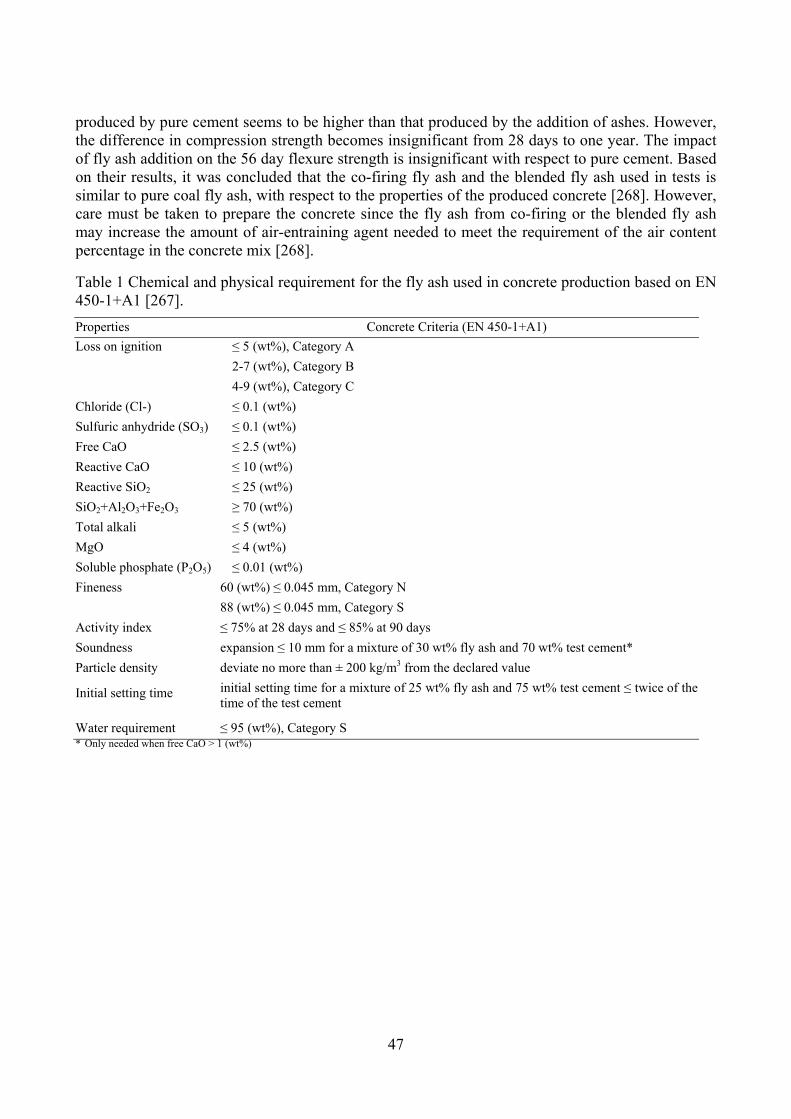
47
produced by pure cement seems to be higher than that produced by the addition of ashes. However, the difference in compression strength becomes insignificant from 28 days to one year. The impact of fly ash addition on the 56 day flexure strength is insignificant with respect to pure cement. Based on their results, it was concluded that the co-firing fly ash and the blended fly ash used in tests is similar to pure coal fly ash, with respect to the properties of the produced concrete [268]. However, care must be taken to prepare the concrete since the fly ash from co-firing or the blended fly ash may increase the amount of air-entraining agent needed to meet the requirement of the air content percentage in the concrete mix [268].
Table 1 Chemical and physical requirement for the fly ash used in concrete production based on EN 450-1+A1 [267].
Properties Concrete Criteria (EN 450-1+A1)
Loss on ignition ≤ 5 (wt%), Category A
2-7 (wt%), Category B
4-9 (wt%), Category C
Chloride (Cl-) ≤ 0.1 (wt%)
Sulfuric anhydride (SO3) ≤ 0.1 (wt%)
Free CaO ≤ 2.5 (wt%)
Reactive CaO ≤ 10 (wt%)
Reactive SiO2 ≤ 25 (wt%)
SiO2+Al2O3+Fe2O3 ≥ 70 (wt%)
Total alkali ≤ 5 (wt%)
MgO ≤ 4 (wt%)
Soluble phosphate (P2O5) ≤ 0.01 (wt%)
Fineness 60 (wt%) ≤ 0.045 mm, Category N
88 (wt%) ≤ 0.045 mm, Category S
Activity index ≤ 75% at 28 days and ≤ 85% at 90 days
Soundness expansion ≤ 10 mm for a mixture of 30 wt% fly ash and 70 wt% test cement*
Particle density deviate no more than ± 200 kg/m3 from the declared value
Initial setting time initial setting time for a mixture of 25 wt% fly ash and 75 wt% test cement ≤ twice of the time of the test cement
Water requirement ≤ 95 (wt%), Category S * Only needed when free CaO > 1 (wt%)

48
References
[1] Leckner B. Co-combustion: A summary of technology. Thermal Science 2007;11:5-40.
[2] Sami M, Annamalai K, Wooldridge M. Co-firing of coal and biomass fuel blends. Prog Energy Combust Sci 2001;27:171-214.
[3] Baxter L Biomass-Coal Cofiring: an Overview of Technical Issues. In: Grammelis P, editor. Solid Biofuels for Energy. : Springer, 2011:43-73.
[4] Baxter L. Biomass-coal co-combustion: opportunity for affordable renewable energy. Fuel 2005;84:1295-302.
[5] Nussbaumer T. Combustion and co-combustion of biomass: fundamentals, technologies, and primary measures for emission reduction. Energy Fuels 2003;17:1510-21.
[6] Hupa M. Interaction of fuels in co-firing in FBC. Fuel 2005;84:1312-9.
[7] Tillman DA. Biomass cofiring: the technology, the experience, the combustion consequences. Biomass Bioenergy 2000;19:365-84.
[8] Sondreal EA, Benson SA, Hurley JP, et al. Review of advances in combustion technology and biomass cofiring. Fuel Process Technol 2001;71:7-38.
[9] Spliethoff H, Hein KRG. Effect of co-combustion of biomass on emissions in pulverized fuel furnaces. Fuel Process Technol 1998;54:189-205.
[10] Niksa S, Liu G, Hurt RH. Coal conversion submodels for design applications at elevated pressures. Part I. devolatilization and char oxidation. Prog Energy Combust Sci 2003;29:425-77.
[11] Solomon PR, Serio MA, Suuberg EM. Coal pyrolysis: Experiments, kinetic rates and mechanisms. Prog Energy Combust Sci 1992;18:133-220.
[12] Glarborg P, Jensen AD, Johnsson JE. Fuel nitrogen conversion in solid fuel fired systems. Prog Energy Combust Sci 2003;29:89-113.
[13] Solomon P, Fletcher T, Pugmire R. Progress in coal pyrolysis. Fuel 1993;72:587-97.
[14] Fletcher TH, Kerstein AR, Pugmire RJ, Solum MS, Grant DM. Chemical percolation model for devolatilization. 3. Direct use of carbon-13 NMR data to predict effects of coal type. Energy Fuels 1992;6:414-31.
[15] Chen JC, Niksa S. Coal devolatilization during rapid transient heating. 1. Primary devolatilization. Energy Fuels 1992;6:254-64.
[16] Serio MA, Hamblen DG, Markham JR, Solomon PR. Kinetics of volatile product evolution in coal pyrolysis: experiment and theory. Energy Fuels 1987;1:138-52.
[17] Suuberg EM, Peters WA, Howard JB. Proc Combust Inst 1979;17:117-30.
[18] Xu WC, Tomita A. Effect of coal type on the flash pyrolysis of various coals. Fuel 1987;66:627-31.
[19] Griffin TP, Howard JB, Peters WA. Pressure and temperature effects in bituminous coal pyrolysis: experimental observations and a transient lumped-parameter model. Fuel 1994;73:591-601.

49
[20] Xu WC, Tomita A. Effect of temperature on the flash pyrolysis of various coals. Fuel 1987;66:632-6.
[21] Chen JC, Castagnoli C, Niksa S. Coal devolatilization during rapid transient heating. 2. Secondary pyrolysis. Energy Fuels 1992;6:264-71.
[22] Zhang H, Fletcher TH. Nitrogen transformations during secondary coal pyrolysis. Energy Fuels 2001;15:1512-22.
[23] Xu WC, Tomita A. The effects of temperature and residence time on the secondary reactions of volatiles from coal pyrolysis. Fuel Process Technol 1989;21:25-37.
[24] Serio MA, Peters WA, Howard JB. Kinetics of vapor-phase secondary reactions of prompt coal pyrolysis tars. Ind Eng Chem Res 1987;26:1831-8.
[25] Doolan KR, Mackie JC, Tyler RJ. Coal flash pyrolysis: secondary cracking of tar vapours in the range 870-2000 K. Fuel 1987;66:572-8.
[26] Jenkins BM, Baxter LL, Miles Jr TR, Miles TR. Combustion properties of biomass. Fuel Process Technol 1998;54:17-46.
[27] Mohan D, Pittman Jr CU, Steele PH. Pyrolysis of wood/biomass for bio-oil: a critical review. Energy Fuels 2006;20:848-89.
[28] Di Blasi C. Combustion and gasification rates of lignocellulosic chars. Prog Energy Combust Sci 2009;35:121-40.
[29] Grammelis P, Basinas P, Malliopoulou A, Sakellaropoulos G. Pyrolysis kinetics and combustion characteristics of waste recovered fuels. Fuel 2009;88:195-205.
[30] Sørum L, Grønli MG, Hustad JE. Pyrolysis characteristics and kinetics of municipal solid wastes. Fuel 2001;80:1217-27.
[31] Heikkinen JM, Hordijk JC, De Jong W, Spliethoff H. Thermogravimetry as a tool to classify waste components to be used for energy generation. J Anal Appl Pyrolysis 2004;71:883-900.
[32] Zevenhoven R, Axelsen EP, Hupa M. Pyrolysis of waste-derived fuel mixtures containing PVC. Fuel 2002;81:507-10.
[33] De Jong W, Di Nola G, Venneker B, Spliethoff H, Wójtowicz M. TG-FTIR pyrolysis of coal and secondary biomass fuels: determination of pyrolysis kinetic parameters for main species and NOx precursors. Fuel 2007;86:2367-76.
[34] Vuthaluru HB. Investigations into the pyrolytic behaviour of coal/biomass blends using thermogravimetric analysis. Bioresour Technol 2004;92:187-95.
[35] Collot AG, Zhuo Y, Dugwell DR, Kandiyoti R. Co-pyrolysis and co-gasification of coal and biomass in bench-scale fixed-bed and fluidised bed reactors. Fuel 1999;78:667-79.
[36] Park DK, Kim SD, Lee SH, Lee JG. Co-pyrolysis characteristics of sawdust and coal blend in TGA and a fixed bed reactor. Bioresour Technol 2010;101:6151-6.
[37] Cordero T, Rodriguez-Mirasol J, Pastrana J, Rodriguez JJ. Improved solid fuels from co-pyrolysis of a high-sulphur content coal and different lignocellulosic wastes. Fuel 2004;83:1585-90.
[38] Ulloa CA, Gordon AL, Garcia XA. Thermogravimetric study of interactions in the pyrolysis of blends of coal with radiata pine sawdust. Fuel Process Technol 2009;90:583-90.
50
[39] Jones JM, Kubacki M, Kubica K, Ross AB, Williams A. Devolatilisation characteristics of coal and biomass blends. J Anal Appl Pyrolysis 2005;74:502-11.
[40] Haykiri-Acma H, Yaman S. Interaction between biomass and different rank coals during co-pyrolysis. Renewable Energy 2010;35:288-92.
[41] Moghtaderi B, Meesri C, Wall TF. Pyrolytic characteristics of blended coal and woody biomass. Fuel 2004;83:745-50.
[42] Zhang L, Xu S, Zhao W, Liu S. Co-pyrolysis of biomass and coal in a free fall reactor. Fuel 2007;86:353-9.
[43] Idris SS, Rahman NA, Ismail K, Alias AB, Rashid ZA, Aris MJ. Investigation on thermochemical behaviour of low rank Malaysian coal, oil palm biomass and their blends during pyrolysis via thermogravimetric analysis (TGA). Bioresour Technol 2010;101:4584-92.
[44] Biagini E, Lippi F, Petarca L, Tognotti L. Devolatilization rate of biomasses and coal-biomass blends: an experimental investigation. Fuel 2002;81:1041-50.
[45] Vamvuka D, Troulinos S, Kastanaki E. The effect of mineral matter on the physical and chemical activation of low rank coal and biomass materials. Fuel 2006;85:1763-71.
[46] Raveendran K, Ganesh A, Khilar KC. Influence of mineral matter on biomass pyrolysis characteristics. Fuel 1995;74:1812-22.
[47] Jensen A, Dam-Johansen K, Wójtowicz MA, Serio MA. TG-FTIR study of the influence of potassium chloride on wheat straw pyrolysis. Energy Fuels 1998;12:929-38.
[48] Skodras G, Grammelis P, Basinas P. Pyrolysis and combustion behaviour of coal-MBM blends. Bioresour Technol 2007;98:1-8.
[49] Cai J, Wang Y, Zhou L, Huang Q. Thermogravimetric analysis and kinetics of coal/plastic blends during co-pyrolysis in nitrogen atmosphere. Fuel Process Technol 2008;89:21-7.
[50] Sharma S, Ghoshal AK. Study of kinetics of co-pyrolysis of coal and waste LDPE blends under argon atmosphere. Fuel 2010;89:3943-51.
[51] Sharypov VI, Beregovtsova NG, Kuznetsov BN, et al. Influence of reaction parameters on brown coal-polyolefinic plastic co-pyrolysis behavior. J Anal Appl Pyrolysis 2007;78:257-64.
[52] Matsuzawa Y, Ayabe M, Nishino J. Acceleration of cellulose co-pyrolysis with polymer. Polym Degrad Stab 2001;71:435-44.
[53] Du X, Annamalai K. The transient ignition of isolated coal particle. Combust Flame 1994;97:339-54.
[54] Essenhigh RH, Misra MK, Shaw DW. Ignition of coal particles: a review. Combust Flame 1989;77:3-30.
[55] Sun CL, Zhang MY. Ignition of Coal Particles at High Pressure in a Thermogravimetric Analyzer. Combust Flame 1998;115:267-74.
[56] Katalambula H, Hayashi J, Chiba T, Kitano K, Ikeda K. Dependence of single coal particle ignition mechanism on the surrounding volatile matter cloud. Energy Fuels 1997;11:1033-9.
[57] Du X, Gopalakrishnan C, Annamalai K. Ignition and combustion of coal particle streams. Fuel 1995;74:487-94.

51
[58] Zhao Y, Kim HY, Yoon SS. Transient group combustion of the pulverized coal particles in spherical cloud. Fuel 2007;86:1102-11.
[59] Wendt C, Eigenbrod C, Moriue O, Rath HJ. A model for devolatilization and ignition of an axisymmetric coal particle. Proc Combust Inst 2002;29:449-57.
[60] Pedersen LS, Nielsen HP, Kiil S, et al. Full-scale co-firing of straw and coal. Fuel 1996;75:1584-90.
[61] Hansen PFB, Andersen KH, Wieck-Hansen K, et al. Co-firing straw and coal in a 150-MWe utility boiler: in situ measurements. Fuel Process Technol 1998;54:207-25.
[62] Andersen KH, Frandsen FJ, Hansen PFB, et al. Deposit formation in a 150 MWe utility PF-boiler during co-combustion of coal and straw. Energy Fuels 2000;14:765-80.
[63] Ballester J, Barroso J, Cerecedo LM, Ichaso R. Comparative study of semi-industrial-scale flames of pulverized coals and biomass. Combust Flame 2005;141:204-15.
[64] Damstedt B, Pederson JM, Hansen D, et al. Biomass cofiring impacts on flame structure and emissions. Proc Combust Inst 2007;31:2813-20.
[65] Yin C, Kær SK, Rosendahl L, Hvid SL. Co-firing straw with coal in a swirl-stabilized dual-feed burner: Modelling and experimental validation. Bioresour Technol 2010;101:4169-78.
[66] Lu H, Robert W, Peirce G, Ripa B, Baxter LL. Comprehensive study of Biomass particle combustion. Energy Fuels 2008;22:2826-39.
[67] Abbas T, Costen P, Kandamby NH, Lockwood FC, Ou JJ. The influence of burner injection mode on pulverized coal and biomass co-fired flames. Combust Flame 1994;99:617-25.
[68] Lu G, Yan Y, Cornwell S, Whitehouse M, Riley G. Impact of co-firing coal and biomass on flame characteristics and stability. Fuel 2008;87:1133-40.
[69] Gani A, Morishita K, Nishikawa K, Naruse I. Characteristics of co-combustion of low-rank coal with biomass. Energy Fuels 2005;19:1652-9.
[70] Arias B, Pevida C, Rubiera F, Pis JJ. Effect of biomass blending on coal ignition and burnout during oxy-fuel combustion. Fuel 2008;87:2753-9.
[71] Hurt RH. Structure, properties, and reactivity of solid fuels. Proc Combust Inst 1998;27:2887-904.
[72] Pedersen KH, Jensen AD, Skjøth-Rasmussen MS, Dam-Johansen K. A review of the interference of carbon containing fly ash with air entrainment in concrete. Prog Energy Combust Sci 2008;34:135-54.
[73] Lang T, Hurt RH. Char combustion reactivities for a suite of diverse solid fuels and char-forming organic model compounds. Proc Combust Inst 2002;29:423-31.
[74] Campbell PA, Mitchell RE, Ma L. Characterization of coal char and biomass char reactivities to oxygen. Proc Combust Inst 2002;29:519-26.
[75] Zolin A, Jensen A, Dam-Johansen K. Kinetic analysis of char thermal deactivation. Proc Combust Inst 2000;28:2181-8.
[76] Zolin A, Jensen AD, Jensen PA, Dam-Johansen K. Experimental study of char thermal deactivation. Fuel 2002;81:1065-75.

52
[77] Kastanaki E, Vamvuka D. A comparative reactivity and kinetic study on the combustion of coal-biomass char blends. Fuel 2006;85:1186-93.
[78] Zolin A, Jensen A, Jensen PA, Frandsen F, Dam-Johansen K. The influence of inorganic materials on the thermal deactivation of fuel chars. Energy Fuels 2001;15:1110-22.
[79] Wieck-Hansen K, Overgaard P, Larsen OH. Cofiring coal and straw in a 150 MWe power boiler experiences. Biomass Bioenergy 2000;19:395-409.
[80] Kostamo JA. Co-firing of sawdust in a coal fired utility boiler. IFRF Combustion Journal 2000.
[81] Kruczek H, RĄCzka P, Tatarek A. The effect of biomass on pollutant emission and burnout in co-combustion with coal. Combust Sci Technol 2006;178:1511-39.
[82] Munir S, Nimmo W, Gibbs BM. The effect of air staged, co-combustion of pulverised coal and biomass blends on NOx emissions and combustion efficiency. Fuel 2011;90:126-35.
[83] Smart JP, Patel R, Riley GS. Oxy-fuel combustion of coal and biomass, the effect on radiative and convective heat transfer and burnout. Combust Flame 2010;157:2230-40.
[84] Gera D, Mathur MP, Freeman MC, Robinson A. Effect of large aspect ratio of biomass particles on carbon burnout in a utility boiler. Energy Fuels 2002;16:1523-32.
[85] Boylan DM. Southern company tests of wood/coal cofiring in pulverized coal units. Biomass Bioenergy 1996;10:139-47.
[86] Lang T, Jensen AD, Jensen PA. Retention of organic elements during solid fuel pyrolysis with emphasis on the peculiar behavior of nitrogen. Energy Fuels 2005;19:1631-43.
[87] Tian FJ, Yu J, McKenzie LJ, Hayashi J, Li CZ. Conversion of fuel-N into HCN and NH3 during the pyrolysis and gasification in steam: a comparative study of coal and biomass. Energy Fuels 2007;21:517-21.
[88] Di Nola G, de Jong W, Spliethoff H. TG-FTIR characterization of coal and biomass single fuels and blends under slow heating rate conditions: Partitioning of the fuel-bound nitrogen. Fuel Process Technol 2010;91:103-15.
[89] Di Nola G, de Jong W, Spliethoff H. The fate of main gaseous and nitrogen species during fast heating rate devolatilization of coal and secondary fuels using a heated wire mesh reactor. Fuel Process Technol 2009;90:388-95.
[90] Li CZ, Tan LL. Formation of NOx and SOx precursors during the pyrolysis of coal and biomass. Part III. Further discussion on the formation of HCN and NH3 during pyrolysis. Fuel 2000;79:1899-906.
[91] Pedersen LS, Morgan DJ, Van de Kamp WL, Christensen J, Jespersen P, Dam-Johansen K. Effects on SOx and NOx emissions by co-firing straw and pulverized coal. Energy Fuels 1997;11:439-46.
[92] Annamalai K, Thien B, Sweeten J. Co-firing of coal and cattle feedlot biomass (FB) fuels. Part II. Performance results from 30 kWt (100,000) BTU/h laboratory scale boiler burner. Fuel 2003;82:1183-93.
[93] Robinson AL, Junker H, Buckley SG, Sclippa G, Baxter LL. Interactions between coal and biomass when cofiring. Proc Combust Inst 1998;27:1351-9.
[94] Vilas E, Skifter U, Jensen AD, López C, Maier J, Glarborg P. Experimental and modeling study of biomass reburning. Energy Fuels 2004;18:1442-50.
53
[95] Harding NS, Adams BR. Biomass as a reburning fuel: a specialized cofiring application. Biomass Bioenergy 2000;19:429-45.
[96] Wei X, Lopez C, von Puttkamer T, Schnell U, Unterberger S, Hein KRG. Assessment of Chlorine− Alkali− Mineral Interactions during Co-Combustion of Coal and Straw. Energy Fuels 2002;16:1095-108.
[97] Cao Y, Zhou HC, Jiang W, Chen CW, Pan WP. Studies of the Fate of Sulfur Trioxide in Coal-Fired Utility Boilers Based on Modified Selected Condensation Methods. Environ Sci Technol 2010;44:3429-34.
[98] Leckner B, Karlsson M. Gaseous emissions from circulating fluidized bed combustion of wood. Biomass Bioenergy 1993;4:379-89.
[99] Zheng Y, Jensen PA, Jensen AD, Sander B, Junker H. Ash transformation during co-firing coal and straw. Fuel 2007;86:1008-20.
[100] Robinson AL, Junker H, Baxter LL. Pilot-scale investigation of the influence of coal-biomass cofiring on ash deposition. Energy Fuels 2002;16:343-55.
[101] Kupka T, Mancini M, Irmer M, Weber R. Investigation of ash deposit formation during co-firing of coal with sewage sludge, saw-dust and refuse derived fuel. Fuel 2008;87:2824-37.
[102] Ferrer E, Aho M, Silvennoinen J, Nurminen RV. Fluidized bed combustion of refuse-derived fuel in presence of protective coal ash. Fuel Process Technol 2005;87:33-44.
[103] Fernandez A, Wendt JOL, Wolski N, Hein KRG, Wang S, Witten ML. Inhalation health effects of fine particles from the co-combustion of coal and refuse derived fuel. Chemosphere 2003;51:1129-37.
[104] Wei X, Wang Y, Liu D, Sheng H, Tian W, Xiao Y. Release of Sulfur and Chlorine during Cofiring RDF and Coal in an Internally Circulating Fluidized Bed. Energy Fuels 2009;23:1390-7.
[105] Vassilev SV, Baxter D, Andersen LK, Vassileva CG. An overview of the chemical composition of biomass. Fuel 2010;89:913-33.
[106] Vainikka P, Enestam S, Silvennoinen J, et al. Bromine as an ash forming element in a fluidised bed boiler combusting solid recovered fuel. Fuel 2011;90:1101-12.
[107] Zheng Y, Jensen PA, Jensen AD. A kinetic study of gaseous potassium capture by coal minerals in a high temperature fixed-bed reactor. Fuel 2008;87:3304-12.
[108] Cenni R, Frandsen F, Gerhardt T, Spliethoff H, Hein KRG. Study on trace metal partitioning in pulverized combustion of bituminous coal and dry sewage sludge. Waste Manage 1998;18:433-44.
[109] Seames WS, Fernandez A, Wendt JOL. A study of fine particulate emissions from combustion of treated pulverized municipal sewage sludge. Environ Sci Technol 2002;36:2772-6.
[110] Yao H, Mkilaha ISN, Naruse I. Screening of sorbents and capture of lead and cadmium compounds during sewage sludge combustion. Fuel 2004;83:1001-7.
[111] Werther J, Ogada T. Sewage sludge combustion. Prog Energy Combust Sci 1999;25:55-116.
[112] Sweeten JM, Annamalai K, Thien B, McDonald LA. Co-firing of coal and cattle feedlot biomass (FB) fuels. Part I. Feedlot biomass (cattle manure) fuel quality and characteristics* 1. Fuel 2003;82:1167-82.
54
[113] Tortosa Masiá AA, Buhre BJP, Gupta RP, Wall TF. Characterising ash of biomass and waste. Fuel Process Technol 2007;88:1071-81.
[114] Sable SP, De Jong W, Meij R, Spliethoff H. Effect of secondary fuels and combustor temperature on mercury speciation in pulverized fuel CO-combustion: Part 1. Energy Fuels 2007;21:1883-90.
[115] Lindström E, Sandström M, Boström D, Öhman M. Slagging characteristics during combustion of cereal grains rich in phosphorus. Energy Fuels 2007;21:710-7.
[116] Bäfver LS, Rönnbäck M, Leckner B, Claesson F, Tullin C. Particle emission from combustion of oat grain and its potential reduction by addition of limestone or kaolin. Fuel Process Technol 2009;90:353-9.
[117] Piotrowska P, Zevenhoven M, Davidsson K, et al. Fate of Alkali Metals and Phosphorus of Rapeseed Cake in Circulating Fluidized Bed Boiler Part 1: Cocombustion with Wood. Energy Fuels 2010;24:333-45.
[118] Piotrowska P, Zevenhoven M, Davidsson K, et al. Fate of Alkali Metals and Phosphorus of Rapeseed Cake in Circulating Fluidized Bed Boiler Part 2: Cocombustion with Coal. Energy Fuels 2010;24:4193-205.
[119] Eriksson G, Hedman H, Boström D, Pettersson E, Backman R, Öhman M. Combustion Characterization of Rapeseed Meal and Possible Combustion Applications. Energy Fuels 2009;23:3930-9.
[120] Davidson RM, Clarke LB. Trace elements in coal. : IEA Coal Research, 1996.
[121] Lighty JS, Veranth JM, Sarofim AF. Combustion aerosols: factors governing their size and composition and implications to human health. J Air Waste Manage Assoc 2000;50:1565-618.
[122] Gupta RP, Wall TF, Kajigaya I, Miyamae S, Tsumita Y. Computer-controlled scanning electron microscopy of minerals in coal--Implications for ash deposition. Prog Energy Combust Sci 1998;24:523-43.
[123] Huggins FE. Overview of analytical methods for inorganic constituents in coal. Int J Coal Geol 2002;50:169-214.
[124] Benson SA, Holm PL. Comparison of inorganic constituents in three low-rank coals. Ind Eng Chem Prod Res Dev 1985;24:145-9.
[125] Miller RN, Given PH. The association of major, minor and trace inorganic elements with lignites. I. Experimental approach and study of a North Dakota lignite. Geochim Cosmochim Acta 1986;50:2033-43.
[126] Baxter LL, Miles TR, Miles Jr TR, et al. The behavior of inorganic material in biomass-fired power boilers: field and laboratory experiences. Fuel Process Technol 1998;54:47-78.
[127] Zevenhoven-Onderwater M, Blomquist JP, Skrifvars BJ, Backman R, Hupa M. The prediction of behaviour of ashes from five different solid fuels in fluidised bed combustion. Fuel 2000;79:1353-61.
[128] Frandsen FJ, van Lith SC, Korbee R, et al. Quantification of the release of inorganic elements from biofuels. Fuel Process Technol 2007;88:1118-28.
[129] Werkelin J, Skrifvars BJ, Zevenhoven M, Holmbom B, Hupa M. Chemical forms of ash-forming elements in woody biomass fuels. Fuel 2010;89:481-93.

55
[130] Miles TR, Miles Jr. TR, Baxter LL, Bryers RW, Jenkin BM, Oden LL. Alkali deposits found in biomass power plants: a preliminary investigation of their extent and nature: Vol I, SAND96-8225, Vol. 2 and NREL/TP-433-8142. 1996.
[131] Pettersson A, Zevenhoven M, Steenari BM, Åmand LE. Application of chemical fractionation methods for characterisation of biofuels, waste derived fuels and CFB co-combustion fly ashes. Fuel 2008;87:3183-93.
[132] Zevenhoven-Onderwater M, Öhman M, Skrifvars BJ, Backman R, Nordin A, Hupa M. Bed agglomeration characteristics of wood-derived fuels in FBC. Energy Fuels 2006;20:818-24.
[133] Aho M, Gil A, Taipale R, Vainikka P, Vesala H. A pilot-scale fireside deposit study of co-firing Cynara with two coals in a fluidised bed. Fuel 2008;87:58-69.
[134] Aho M, Ferrer E. Importance of coal ash composition in protecting the boiler against chlorine deposition during combustion of chlorine-rich biomass. Fuel 2005;84:201-12.
[135] Baxter LL. Ash Deposit Formation and Deposit Properties. A Comprehensive Summary of Research Conducted at Sandia's Combustion Research Facility. Ash Deposit Formation and Deposit Properties.A Comprehensive Summary of Research Conducted at Sandia's Combustion Research FacilitySandia National Labs., Albuquerque, NM (US); Sandia National Labs., Livermore, CA (US), 2000.
[136] Westberg HM, Bystrom M, Leckner B. Distribution of potassium, chlorine, and sulfur between solid and vapor phases during combustion of wood chips and coal. Energy Fuels 2003;17:18-28.
[137] Huggins FE, Seidu LBA, Shah N, et al. Elemental modes of occurrence in an Illinois# 6 coal and fractions prepared by physical separation techniques at a coal preparation plant. Int J Coal Geol 2009;78:65-76.
[138] Zhang L, Ninomiya Y, Yamashita T. Occurrence of inorganic elements in condensed volatile matter emitted from coal pyrolysis and their contributions to the formation of ultrafine particulates during coal combustion. Energy Fuels 2006;20:1482-9.
[139] Wall TF. Mineral matter transformations and ash deposition in pulverised coal combustion. Proc Combust Inst 1992;24:1119-26.
[140] Tillman DA, Duong D, Miller B. Chlorine in solid fuels fired in pulverized fuel boilers - sources, forms, reactions and consequences: a literature review. Energy Fuels 2009;23:3379-91.
[141] van lith SC. Release of inorganic elements during wood-firing on a grate. PhD thesis, Department of Chemical Engineering, Technical University of Denmark, 2005.
[142] Knudsen JN. Volatilization of inorganic matter during combustion of annual biomass. PhD thesis. Department of Chemical Engineering, Technical University of Denmark, 2004.
[143] Calkins WH. The chemical forms of sulfur in coal: a review. Fuel 1994;73:475-84.
[144] Knudsen JN, Jensen PA, Lin W, Frandsen FJ, Dam-Johansen K. Sulfur transformations during thermal conversion of herbaceous biomass. Energy Fuels 2004;18:810-9.
[145] Senior CL, Helble JJ, Sarofim AF. Emissions of mercury, trace elements, and fine particles from stationary combustion sources. Fuel Process Technol 2000;65:263-88.
[146] Linak WP, Wendt JOL. Toxic metal emissions from incineration: mechanisms and control. Prog Energy Combust Sci 1993;19:145-85.

56
[147] Buhre BJP, Hinkley JT, Gupta RP, Wall TF, Nelson PF. Submicron ash formation from coal combustion. Fuel 2005;84:1206-14.
[148] Linak WP, Wendt JOL. Trace metal transformation mechanisms during coal combustion. Fuel Process Technol 1994;39:173-98.
[149] Xu M, Yu D, Yao H, Liu X, Qiao Y. Coal combustion-generated aerosols: Formation and properties. Proc Combust Inst 2011;33:1681-97.
[150] Frandsen FJ, Visser R, Jokiniemi J, Wigley F, Sarofim AF. A humble note on gaps in the understanding of release fly ash and combustion aerosol formation in boilers. Proceedings of the Impacts of Fuel Quality on Power Generation and the Environment, 2010, Lapland, Finland.
[151] Linak WP, Miller CA, Seames WS, et al. On trimodal particle size distributions in fly ash from pulverized-coal combustion. Proc Combust Inst 2002;29:441-7.
[152] Quann RJ, Sarofim AF. Vaporization of refractory oxides during pulverized coal combustion. Proc Combust Inst 1982;19:1429-40.
[153] Neville M, Sarofim AF. The fate of sodium during pulverized coal combustion. Fuel 1985;64:384-90.
[154] Quann RJ, Neville M, Janghorbani M, Mims CA, Sarofim AF. Mineral matter and trace-element vaporization in a laboratory-pulverized coal combustion system. Environ Sci Technol 1982;16:776-81.
[155] Helble JJ, Sarofim AF. Factors determining the primary particle size of flame-generated inorganic aerosols. J Colloid Interface Sci 1989;128:348-62.
[156] Lee CM, Davis KA, Heap MP, Eddings E, Sarofim A. Modeling the vaporization of ash constituents in a coal-fired boiler. Proc Combust Inst 2000;28:2375-82.
[157] Eddings EG, Sarofim AF, Lee CM, Davis KA, Valentine JR. Trends in predicting and controlling ash vaporization in coal-fired utility boilers. Fuel Process Technol 2001;71:39-51.
[158] Flagan RC, Taylor DD. Laboratory studies of submicron particles from coal combustion. Proc Combust Inst 1981;18:1227-37.
[159] Senior CL, Flagan RC. Ash vaporization and condensation during combustion of a suspended coal particle. Aerosol Sci Tech 1982;1:371-83.
[160] Senior CL, Flagan RC. Synthetic chars for the study of ash vaporization. Proc Combust Inst 1984;20:921-9.
[161] McNallan MJ, Yurek GJ, Elliott JF. The formation of inorganic particulates by homogeneous nucleation in gases produced by the combustion of coal. Combust Flame 1981;42:45-60.
[162] Srinivasachar S, Helble JJ, Ham DO, Domazetis G. A kinetic description of vapor phase alkali transformations in combustion systems. Prog Energy Combust Sci 1990;16:303-9.
[163] Lindner ER, Wall TF. Sodium ash reactions during combustion of pulverised coal. Proc Combust Inst 1991;23:1313-21.
[164] Zhang L, Wang Q, Sato A, Ninomiya Y, Yamashitas T. Interactions among Inherent Minerals during Coal Combustion and Their Impacts on the Emission of PM10. 2. Emission of Submicrometer-Sized Particles. Energy Fuels 2007;21:766-77.

57
[165] Korbee R, Shah KV, Cieplik MK, Betrand CI, Vuthaluru HB, van de Kamp WL. First Line Ash Transformations of Coal and Biomass Fuels during PF Combustion. Energy Fuels 2010;24:897-909.
[166] Shah KV, Cieplik MK, Betrand CI, Van de Kamp WL, Vuthaluru HB. Correlating the effects of ash elements and their association in the fuel matrix with the ash release during pulverized fuel combustion. Fuel Process Technol 2010;91:531-45.
[167] Knudsen JN, Jensen PA, Dam-Johansen K. Transformation and release to the gas phase of Cl, K, and S during combustion of annual biomass. Energy Fuels 2004;18:1385-99.
[168] van Lith SC, Jensen PA, Frandsen FJ, Glarborg P. Release to the Gas Phase of Inorganic Elements during Wood Combustion. Part 2: Influence of Fuel Composition. Energy Fuels 2008;22:1598-609.
[169] Novaković A, van Lith SC, Frandsen FJ, Jensen PA, Holgersen LB. Release of Potassium from the Systems K− Ca− Si and K− Ca− P. Energy Fuels 2009;23:3423-8.
[170] van Lith SC, Alonso-Ramírez V, Jensen PA, Frandsen FJ, Glarborg P. Release to the gas phase of inorganic elements during wood combustion. Part 1: development and evaluation of quantification methods. Energy Fuels 2006;20:964-78.
[171] Pedersen AJ, Frandsen FJ, Riber C, et al. A Full-scale Study on the Partitioning of Trace Elements in Municipal Solid Waste Incineration—Effects of Firing Different Waste Types. Energy Fuels 2009;23:3475-89.
[172] Pedersen AJ, Van Lith SC, Frandsen FJ, Steinsen SD, Holgersen LB. Release to the gas phase of metals, S and Cl during combustion of dedicated waste fractions. Fuel Process Technol 2010;91:1062-72.
[173] Jensen PA, Frandsen FJ, Dam-Johansen K, Sander B. Experimental investigation of the transformation and release to gas phase of potassium and chlorine during straw pyrolysis. Energy Fuels 2000;14:1280-5.
[174] Dayton DC, Jenkins BM, Turn SQ, et al. Release of inorganic constituents from leached biomass during thermal conversion. Energy Fuels 1999;13:860-70.
[175] Björkman E, Strömberg B. Release of Chlorine from Biomass at Pyrolysis and Gasification Conditions1. Energy Fuels 1997;11:1026-32.
[176] Wendt JOL, Lee SJ. High-temperature sorbents for Hg, Cd, Pb, and other trace metals: Mechanisms and applications. Fuel 2010;89:894-903.
[177] Gale TK, Wendt JOL. High-temperature interactions between multiple-metals and kaolinite. Combust Flame 2002;131:299-307.
[178] Gallagher NB, Peterson TW, Wendt JOL. Sodium Partitioning in a Pulverized Coal Combustion Environment. Proc Combust Inst 1996;26:3197-204.
[179] Mwabe PO, Wendt JOL. Mechanisms governing trace sodium capture by kaolinite in a downflow combustor. Proc Combust Inst 1996;26:2447-53.
[180] Gale TK, Wendt JOL. Mechanisms and Models Describing Sodium and Lead Scavenging by a Kaolinite Aerosol at High Temperatures. Aerosol Sci Tech 2003;37:865-76.
[181] Takuwa T, Naruse I. Detailed kinetic and control of alkali metal compounds during coal combustion. Fuel Process Technol 2007;88:1029-34.

58
[182] Uberoi M, Punjak WA, Shadman F. The kinetics and mechanism of alkali removal from flue gases by solid sorbents. Prog Energy Combust Sci 1990;16:205-11.
[183] Punjak WA, Uberoi M, Shadman F. High‐temperature adsorption of alkali vapors on solid sorbents. AICHE J 1989;35:1186-94.
[184] Punjak WA, Shadman F. Aluminosilicate sorbents for control of alkali vapors during coal combustion and gasification. Energy Fuels 1988;2:702-8.
[185] Gale TK, Wendt JOL. In-furnace capture of cadmium and other semi-volatile metals by sorbents. Proc Combust Inst 2005;30:2999-3007.
[186] Tran KQ, Iisa K, Steenari BM, Lindqvist O. A kinetic study of gaseous alkali capture by kaolin in the fixed bed reactor equipped with an alkali detector. Fuel 2005;84:169-75.
[187] Steenari BM, Lindqvist O. High-temperature reactions of straw ash and the anti-sintering additives kaolin and dolomite. Biomass Bioenergy 1998;14:67-76.
[188] Kyi S, Chadwick BL. Screening of potential mineral additives for use as fouling preventatives in Victorian brown coal combustion. Fuel 1999;78:845-55.
[189] Dou B, Shen W, Gao J, Sha X. Adsorption of alkali metal vapor from high-temperature coal-derived gas by solid sorbents. Fuel Process Technol 2003;82:51-60.
[190] Wu B, Jaanu KK, Shadman F. Multi-functional sorbents for the removal of sulfur and metallic contaminants from high-temperature gases. Environ Sci Technol 1995;29:1660-5.
[191] Iisa K, Lu Y, Salmenoja K. Sulfation of potassium chloride at combustion conditions. Energy Fuels 1999;13:1184-90.
[192] Glarborg P, Marshall P. Mechanism and modeling of the formation of gaseous alkali sulfates. Combust Flame 2005;141:22-39.
[193] Glarborg P. Hidden interactions--Trace species governing combustion and emissions. Proc Combust Inst 2007;31:77-98.
[194] Hindiyarti L, Frandsen F, Livbjerg H, Glarborg P, Marshall P. An exploratory study of alkali sulfate aerosol formation during biomass combustion. Fuel 2008;87:1591-600.
[195] Steinberg M, Schofield K. The controlling chemistry in flame generated surface deposition of Na2SO4 and the effects of chlorine. Proc Combust Inst 1996;26:1835-43.
[196] Wolf KJ, Smeda A, Müller M, Hilpert K. Investigations on the influence of additives for SO2 reduction during high alkaline biomass combustion. Energy Fuels 2005;19:820-4.
[197] Aho M, Vainikka P, Taipale R, Yrjas P. Effective new chemicals to prevent corrosion due to chlorine in power plant superheaters. Fuel 2008;87:647-54.
[198] Davidsson KO, Åmand LE, Steenari BM, Elled AL, Eskilsson D, Leckner B. Countermeasures against alkali-related problems during combustion of biomass in a circulating fluidized bed boiler. Chemical Engineering Science 2008;63:5314-29.
[199] Kassman H, Bäfver L, Åmand LE. The importance of SO2 and SO3 for sulphation of gaseous KCl-An experimental investigation in a biomass fired CFB boiler. Combust Flame 2010;157:1649-57.
[200] Steinberg M, Schofield K. The chemistry of sodium with sulfur in flames. Prog Energy Combust Sci 1990;16:311-7.

59
[201] Schofield K, Steinberg M. Sodium/sulfur chemical behavior in fuel-rich and-lean flames. J Phys Chem 1992;96:715-26.
[202] Steinberg M, Schofield K. The controlling chemistry of surface deposition from sodium and potassium seeded flames free of sulfur or chlorine impurities. Combust Flame 2002;129:453-70.
[203] Boonsongsup L, Iisa K, Frederick Jr WJ. Kinetics of the sulfation of NaCl at combustion conditions. Ind Eng Chem Res 1997;36:4212-6.
[204] Matsuda H, Ozawa S, Naruse K, Ito K, Kojima Y, Yanase T. Kinetics of HCl emission from inorganic chlorides in simulated municipal wastes incineration conditions. Chem Eng Sci 2005;60:545-52.
[205] Jensen JR, Nielsen LB, Schultz-Møller C, Wedel S, Livbjerg H. The nucleation of aerosols in flue gases with a high content of alkali-A laboratory study. Aerosol Sci Tech 2000;33:490-509.
[206] Christensen KA, Livbjerg H. A plug flow model for chemical reactions and aerosol nucleation and growth in an alkali-containing flue gas. Aerosol Sci Tech 2000;33:470-89.
[207] Christensen KA, Stenholm M, Livbjerg H. The formation of submicron aerosol particles, HCl and SO2 in straw-fired boilers. J Aerosol Sci 1998;29:421-44.
[208] Jimenez S, Ballester J. Effect of co-firing on the properties of submicron aerosols from biomass combustion. Proc Combust Inst 2005;30:2965-72.
[209] Jimenez S, Ballester J. Influence of operating conditions and the role of sulfur in the formation of aerosols from biomass combustion. Combust Flame 2005;140:346-58.
[210] Nielsen HP, Baxter LL, Sclippab G, Morey C, Frandsen FJ, Dam-Johansen K. Deposition of potassium salts on heat transfer surfaces in straw-fired boilers: a pilot-scale study. Fuel 2000;79:131-9.
[211] Frandsen FJ. Utilizing biomass and waste for power production—a decade of contributing to the understanding, interpretation and analysis of deposits and corrosion products. Fuel 2005;84:1277-94.
[212] Broström M, Kassman H, Helgesson A, et al. Sulfation of corrosive alkali chlorides by ammonium sulfate in a biomass fired CFB boiler. Fuel Process Technol 2007;88:1171-7.
[213] McElroy MW, Carr RC, Ensor DS, Markowski GR. Size distribution of fine particles from coal combustion. Science 1982;215:13.
[214] Kauppinen EI, Pakkanen TA. Coal combustion aerosols: a field study. Environ Sci Technol 1990;24:1811-8.
[215] Yi H, Hao J, Duan L, Tang X, Ning P, Li X. Fine particle and trace element emissions from an anthracite coal-fired power plant equipped with a bag-house in China. Fuel 2008;87:2050-7.
[216] Zheng Y, Jensen AD, Johnsson JE. Deactivation of V2O5-WO3-TiO2 SCR catalyst at a biomass-fired combined heat and power plant. Appl Catal B-Environ 2005;60:253-64.
[217] Beck J, Brandenstein J, Unterberger S, Hein KRG. Effects of sewage sludge and meat and bone meal co-combustion on SCR catalysts. Applied Catalysis B: Environmental 2004;49:15-25.
[218] Zhang L, Ninomiya Y, Yamashita T. Formation of submicron particulate matter (PM1) during coal combustion and influence of reaction temperature. Fuel 2006;85:1446-57.

60
[219] Senior CL, Bool LE, Srinivasachar S, Pease BR, Porle K. Pilot scale study of trace element vaporization and condensation during combustion of a pulverized sub-bituminous coal. Fuel Process Technol 2000;63:149-65.
[220] Senior CL, BoolIII LE, Morency JR. Laboratory study of trace element vaporization from combustion of pulverized coal. Fuel Process Technol 2000;63:109-24.
[221] Linak WP, Yoo JI, Wasson SJ, et al. Ultrafine ash aerosols from coal combustion: Characterization and health effects. Proc Combust Inst 2007;31:1929-37.
[222] Yu D, Xu M, Yao H, Liu X, Zhou K. A new method for identifying the modes of particulate matter from pulverized coal combustion. Powder Technol 2007.
[223] Yu D, Xu M, Yao H, et al. Use of elemental size distributions in identifying particle formation modes. Proc Combust Inst 2007;31:1921-8.
[224] Seames WS. An initial study of the fine fragmentation fly ash particle mode generated during pulverized coal combustion. Fuel Process Technol 2003;81:109-25.
[225] Nielsen MT, Livbjerg H, Fogh CL, et al. Formation and emission of fine particles from two coal-fired power plants. Combust Sci Technol 2002;174:79-113.
[226] Nielsen LB, Livbjerg H. Aerosol measurement at MKS1: supplementary measurements 3a, 8a, and 9a. Department of Chemical Engineering, Technical University of Denmark, 1997.
[227] Nielsen LB, Pedersen C, Røkke M, Livbjerg H. Aerosol measurements at MKS1 - final report. Department of Chemical Engineering, Technical University of Denmark, 1996.
[228] Markowski GR, Filby R. Trace element concentration as a function of particle size in fly ash from a pulverized coal utility boiler. Environ Sci Technol 1985;19:796-804.
[229] Skrifvars BJ, Laurén T, Hupa M, Korbee R, Ljung P. Ash behaviour in a pulverized wood fired boiler--a case study. Fuel 2004;83:1371-9.
[230] Tissari J, Sippula O, Kouki J, Vuorio K, Jokiniemi J. Fine particle and gas emissions from the combustion of agricultural fuels fired in a 20 kW burner. Energy Fuels 2008;22:2033-42.
[231] Jimenez S, Ballester J. Particulate matter formation and emission in the combustion of different pulverized biomass fuels. Combustion Sci Technol 2006;178:655-83.
[232] Wolski N, Maier J, Hein KRG. Fine particle formation from co-combustion of sewage sludge and bituminous coal. Fuel Process Technol 2004;85:673-86.
[233] Sarofim AF, Howard JB, Padia AS. The physical transformation of the mineral matter in pulverized coal under simulated combustion conditions. Combustion Sci Technol 1977;16:187-204.
[234] Damle AS, Ensor DS, Ranade MB. Coal combustion aerosol formation mechanisms: a review. Aerosol Sci Tech 1982;1:119-33.
[235] Nielsen LB. Combustion aerosols from potassium-containing fuels, PhD Thesis. Department of Chemical Engineering, Technical University of Denmark, 1998.
[236] Jimenez S. Submicron particle formation in biomass combustion, PhD Thesis. LITEC/Fluid Mechanics Group, University of Zaragoza, Spain, 2004.
[237] Zeuthen JH, Jensen PA, Jensen JP, Livbjerg H. Aerosol formation during the combustion of straw with addition of sorbents. Energy Fuels 2007;21:699-709.

61
[238] Kauppinen EI, Lind TM, Valmari T, et al. The structure of submicron ash from combustion of pulverized South African and Colombian coals. Applications of Advanced Technology to Ash-Related Problems in Boilers 1996:471.
[239] Yan L, Gupta RP, Wall TF. A mathematical model of ash formation during pulverized coal combustion. Fuel 2002;81:337-44.
[240] Helble JJ, Sarofim AF. Influence of char fragmentation on ash particle size distributions. Combust Flame 1989;76:183-96.
[241] Christensen KA, Livbjerg H. A field study of submicron particles from the combustion of straw. Aerosol Sci Tech 1996;25:185-99.
[242] Zeuthen JH. The formation of aerosol particles during combustion of biomass and waste, PhD Thesis. Department of Chemical Engineering, Technical University of Denmark, 2007.
[243] Bryers RW. Fireside slagging, fouling, and high-temperature corrosion of heat-transfer surface due to impurities in steam-raising fuels. Prog Energy Combust Sci 1996;22:29-120.
[244] Baxter LL. Ash deposition during biomass and coal combustion: a mechanistic approach. Biomass Bioenergy 1993;4:85-102.
[245] Nielsen HP. Deposition and high-temperature corrosion in biomass-fired boilers, PhD Thesis. Department of Chemical Engineering, Technical University of Denmark, 1998.
[246] Kupka T, Zając K, Weber R. Effect of Fuel Type and Deposition Surface Temperature on the Growth and Structure of an Ash Deposit Collected during Co-firing of Coal with Sewage Sludge and Sawdust. Energy Fuels 2009;23:3429-36.
[247] Zbogar A, Frandsen F, Jensen PA, Glarborg P. Shedding of ash deposits. Prog Energy Combust Sci 2009;35:31-56.
[248] Heinzel T, Siegle V, Spliethoff H, Hein KRG. Investigation of slagging in pulverized fuel co-combustion of biomass and coal at a pilot-scale test facility. Fuel Process Technol 1998;54:109-25.
[249] Theis M, Skrifvars BJ, Hupa M, Tran H. Fouling tendency of ash resulting from burning mixtures of biofuels. Part 1: Deposition rates. Fuel 2006;85:1125-30.
[250] Theis M, Skrifvars BJ, Zevenhoven M, Hupa M, Tran H. Fouling tendency of ash resulting from burning mixtures of biofuels. Part 2: Deposit chemistry. Fuel 2006;85:1992-2001.
[251] Wigley F, Williamson J, Malmgren A, Riley G. Ash deposition at higher levels of coal replacement by biomass. Fuel Process Technol 2007;88:1148-54.
[252] Fryda L, Sobrino C, Cieplik M, Van de Kamp WL. Study on ash deposition under oxyfuel combustion of coal/biomass blends. Fuel 2010;89:1889-902.
[253] Hansen LA, Frandsen FJ, Dam-Johansen K, Sorensen HS, Skrifvars BJ. Characterization of ashes and deposits from high-temperature coal− straw co-firing. Energy Fuels 1999;13:803-16.
[254] Lokare SS, Dunaway JD, Moulton D, Rogers D, Dale R, Baxter LL. Investigation of ash deposition rates for a suite of biomass fuels and fuel blends. Energy Fuels 2006;20:1008-14.
[255] Bartolomé C, Gil A, Ramos I. Ash deposition behavior of cynara-coal blends in a PF pilot furnace. Fuel Process Technol 2010;91:1576-84.
[256] Abreu P, Casaca C, Costa M. Ash deposition during the co-firing of bituminous coal with pine sawdust and olive stones in a laboratory furnace. Fuel 2010;89:4040-8.

62
[257] Arvelakis S, Frandsen FJ. Rheology of fly ashes from coal and biomass co-combustion. Fuel 2010;89:3132-40.
[258] Arvelakis S, Frandsen FJ. Melting Behavior of Ashes from the Co-combustion of Coal and Straw. Energy Fuels 2007;21:3004-9.
[259] Theis M, Skrifvars BJ, Zevenhoven M, Hupa M, Tran H. Fouling tendency of ash resulting from burning mixtures of biofuels. Part 3. Influence of probe surface temperature. Fuel 2006;85:2002-11.
[260] Weber R, Kupka T, Zając K. Jet flames of a refuse derived fuel. Combust Flame 2009;156:922-7.
[261] Nielsen HP, Frandsen FJ, Dam-Johansen K, Baxter LL. The implications of chlorine-associated corrosion on the operation of biomass-fired boilers. Prog Energy Combust Sci 2000;26:283-98.
[262] Harb JN, Smith EE. Fireside corrosion in pc-fired boilers. Prog Energy Combust Sci 1990;16:169-90.
[263] Montgomery M, Larsen OH. Field test corrosion experiments in Denmark with biomass fuels. Part 2: Co‐firing of straw and coal. Materials and Corrosion 2002;53:185-94.
[264] Montgomery M, Vilhelmsen T, Jensen SA. Potential high temperature corrosion problems due to co‐firing of biomass and fossil fuels. Materials and Corrosion 2008;59:783-93.
[265] Cenni R, Janisch B, Spliethoff H, Hein KRG. Legislative and environmental issues on the use of ash from coal and municipal sewage sludge co-firing as construction material. Waste Manage 2001;21:17-31.
[266] European Committee for Standardization (CEN). EN 197-1: Cement-part 1: composition, specifications and conformity criteria for common cements. 2000.
[267] European Committee for Standardization (CEN). EN 450-1:2005+A1: Fly ash for concrete-part 1: definition, specifications and conformity criteria. 2007.
[268] Wang S, Miller A, Llamazos E, Fonseca F, Baxter L. Biomass fly ash in concrete: Mixture proportioning and mechanical properties. Fuel 2008;87:365-71.
Related Documents


![[8] Principles and Models of Solid Fuel Combustion](https://static.cupdf.com/doc/110x72/544feca9af7959ff088b484f/8-principles-and-models-of-solid-fuel-combustion.jpg)