Report On Steam Power Plant Submitted to Mafizul Haque Faculty, Dept. of Mechanical Engieering Submitted by Group-3 Sl Name ID 1. Saddam Hussain Sohag 10107077 2. Md. Jahiduzzaman Rubel 10307029 3. Md. Mohsin Uddin 10307019 4. Mohammad Mojibur Rahman Chowdhury 10307027 5. Sohag Biswas 10307036 Date of Submission: April 5, 2014

Welcome message from author
This document is posted to help you gain knowledge. Please leave a comment to let me know what you think about it! Share it to your friends and learn new things together.
Transcript
Report On
Steam Power Plant
Submitted to Mafizul Haque
Faculty, Dept. of Mechanical Engieering
Submitted by Group-3 Sl Name ID 1. Saddam Hussain Sohag 10107077 2. Md. Jahiduzzaman Rubel 10307029 3. Md. Mohsin Uddin 10307019 4. Mohammad Mojibur Rahman Chowdhury 10307027 5. Sohag Biswas 10307036
Date of Submission: April 5, 2014

Table of Contents 1. Introduction
1.1 History 1.2 Objectives
2. Theory 2.1 The Ideal Reheat Rankine Cycle 2.2 A Reheat Rankine-Cycle Power Plant
3. Description of Steam Power Plant 3.1 Boiler 3.1.1 Essentials of Steam Power Plant Equipment 3.1.2 Steam production 3.1.3 Types of Boilers 3.1.4 Major Components of ST and Their Functions 3.2 Super Heater 3.2.1 Types of Super Heater 3.2.2 Steam Temperature Control 3.3 Feed Water Heater 3.4 Steam Turbines 3.4.1 Types 3.4.2 Steam Turbine Classification 3.4.3 Principle of Operation and Design 3.4.4 Turbine Efficiency 3.4.5 Impulse Turbines 3.4.6 Reaction Turbines 3.5 Condenser 3.5.1 Functions of Condensers 3.5.2 Condenser Types 3.5.3 Surface Condenser 3.6 Cooling Tower 3.6.1 Cooling Tower 3.6.2 Cooling Towers Working Procedure 3.6.3 Types of Cooling Towers 3.7 Steam Power Station Control 3.7.1 Basic Components of a Control System
4. Steam power plant in Bangladesh 5. Recommendation 6. Conclusions
Steam Power Plant
1. Introduction:
A steam power station is a power plant in which the prime mover is
steam driven. Water is heated, turns into steam and spins a steam turbine which
either drives an electrical generator or does some other work, like ship
propulsion. After it passes through the turbine, the steam is condensed in a
condenser and recycled to where it was heated; this is known as a Rankine cycle.
The greatest variation in the design of steam power stations is due to the
different fuel sources. Some prefer to use the term energy center because such
facilities convert forms of heat energy into electrical energy.
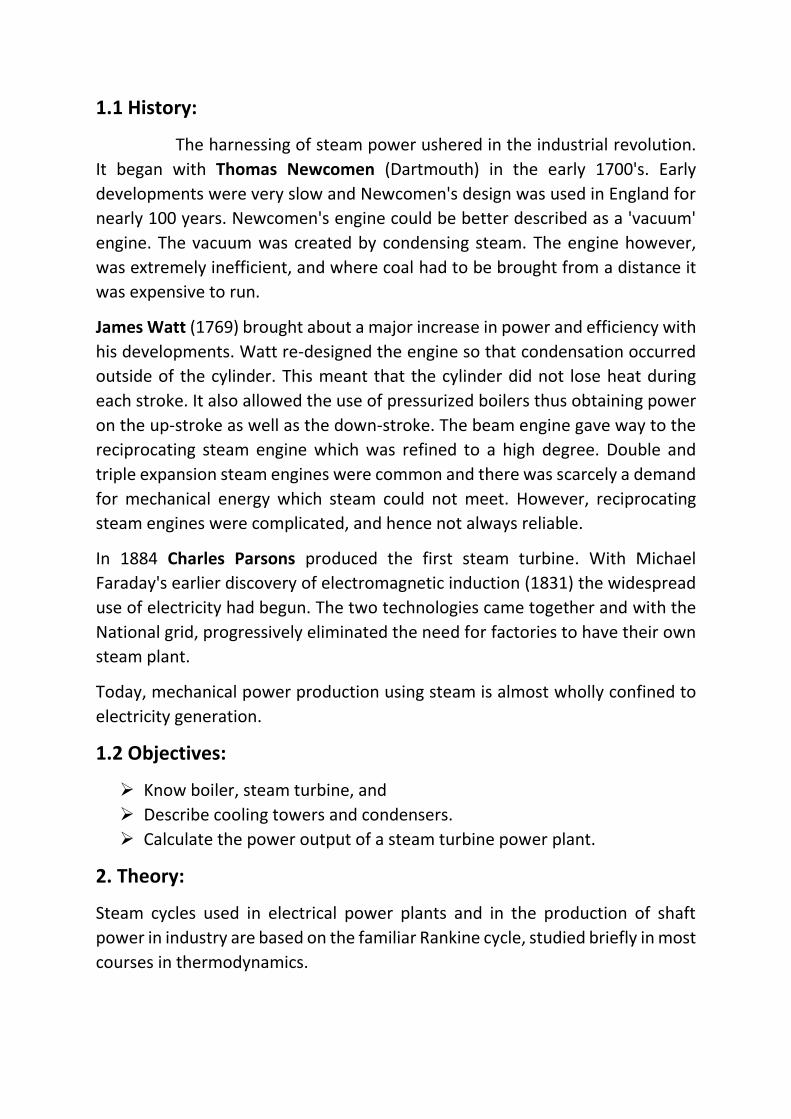
Power Plants is an establishment for power generation. In Bangladesh, the
consumption of per capita generation is very low only 220 kWh. Presently about
47% of the total population have access to electricity. Bangladesh Power
Development Board (BPDB) is the sole government authority for generation of
electricity. Major power distribution agencies include the BPDB itself and the
rural electrification board (REB). The Dhaka Electric Supply Authority (desa) and
Dhaka Electric Supply Company (DESCO) for Dhaka or the Khulna Electric Supply
Company (KESCO) for Khulna. The power division of the Ministry of Energy and
Mineral Resources is the umbrella organization that controls power generation,
transmission and distribution. An Independent Power Project (IPP) of the
ministry is under implementation for improvement in generation and
distribution of electricity by government and private agencies.
1.1 History:
The harnessing of steam power ushered in the industrial revolution.
It began with Thomas Newcomen (Dartmouth) in the early 1700's. Early
developments were very slow and Newcomen's design was used in England for
nearly 100 years. Newcomen's engine could be better described as a 'vacuum'
engine. The vacuum was created by condensing steam. The engine however,
was extremely inefficient, and where coal had to be brought from a distance it
was expensive to run.
James Watt (1769) brought about a major increase in power and efficiency with
his developments. Watt re-designed the engine so that condensation occurred
outside of the cylinder. This meant that the cylinder did not lose heat during
each stroke. It also allowed the use of pressurized boilers thus obtaining power
on the up-stroke as well as the down-stroke. The beam engine gave way to the
reciprocating steam engine which was refined to a high degree. Double and
triple expansion steam engines were common and there was scarcely a demand
for mechanical energy which steam could not meet. However, reciprocating
steam engines were complicated, and hence not always reliable.
In 1884 Charles Parsons produced the first steam turbine. With Michael
Faraday's earlier discovery of electromagnetic induction (1831) the widespread
use of electricity had begun. The two technologies came together and with the
National grid, progressively eliminated the need for factories to have their own
steam plant.
Today, mechanical power production using steam is almost wholly confined to
electricity generation.
1.2 Objectives:
Know boiler, steam turbine, and
Describe cooling towers and condensers.
Calculate the power output of a steam turbine power plant.
2. Theory:
Steam cycles used in electrical power plants and in the production of shaft
power in industry are based on the familiar Rankine cycle, studied briefly in most
courses in thermodynamics.
2.1 The Ideal Reheat Rankine Cycle:
The efficiency of the Rankine cycle can increase by expanding the steam in the
turbine in two stages, and reheating it in between. Reheating is a practical
solution to the excessive moisture problem in turbines, and it is commonly used
in modern steam power plants.
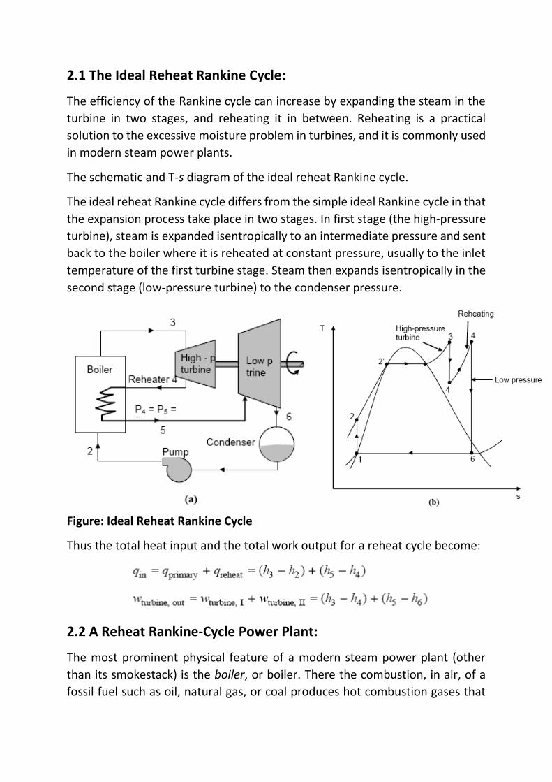
The schematic and T-s diagram of the ideal reheat Rankine cycle.
The ideal reheat Rankine cycle differs from the simple ideal Rankine cycle in that
the expansion process take place in two stages. In first stage (the high-pressure
turbine), steam is expanded isentropically to an intermediate pressure and sent
back to the boiler where it is reheated at constant pressure, usually to the inlet
temperature of the first turbine stage. Steam then expands isentropically in the
second stage (low-pressure turbine) to the condenser pressure.
Figure: Ideal Reheat Rankine Cycle
Thus the total heat input and the total work output for a reheat cycle become:
2.2 A Reheat Rankine-Cycle Power Plant:
The most prominent physical feature of a modern steam power plant (other
than its smokestack) is the boiler, or boiler. There the combustion, in air, of a
fossil fuel such as oil, natural gas, or coal produces hot combustion gases that
transfer heat to water passing through tubes in the boiler. The heat transfer to
the incoming water (feed water) first increases its temperature until it becomes
a saturated liquid, then evaporates it to form saturated vapor, and usually then
further raises its temperature to create superheated steam.
Steam power plants operate on sophisticated variants of the Rankine cycle.
These are considered later. The simple Rankine cycle from which the cycles of
large steam power plants are derived.
In the simple Rankine cycle, steam flows to a turbine, where part of its energy is
converted to mechanical energy that is transmitted by rotating shaft to drive an
electrical generator. The reduced-energy steam flowing out of the turbine
condenses to liquid water in the condenser. A feed water pump returns the
condensed liquid (condensate) to the boiler. The heat rejected from the steam
entering the condenser is transferred to a separate cooling water loop that in
turn delivers the rejected energy to a neighboring lake or river or to the
atmosphere.
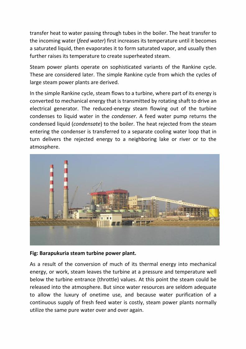
Fig: Barapukuria steam turbine power plant.
As a result of the conversion of much of its thermal energy into mechanical
energy, or work, steam leaves the turbine at a pressure and temperature well
below the turbine entrance (throttle) values. At this point the steam could be
released into the atmosphere. But since water resources are seldom adequate
to allow the luxury of onetime use, and because water purification of a
continuous supply of fresh feed water is costly, steam power plants normally
utilize the same pure water over and over again.

We usually say that the working fluid (water) in the plant operates in a cycle or
undergoes of cyclic process. In order to return the steam to the high-pressure of
the boiler to continue the cycle, the low- pressure steam leaving the turbine at
state 2 is first condensed to a liquid at state 3 and then pressurized in a pump to
state 4. The high pressure liquid water is then ready for its next pass through the
boiler to state 1 and around the Rankine cycle again.
The boiler and condenser both may be thought of as types of heat exchangers,
the former with hot combustion gases flowing on the outside of water filled
tubes, and the latter with external cooling water passing through tubes on which
the low- pressure turbine exhaust steam condenses. In a well-designed heat
exchanger, both fluids pass through with little pressure loss.
Figure: Ideal Reheat Rankine Cycle
Therefore, as an ideal, it is common to think of boilers and condensers as
operating with their fluids at unchanging pressures.
It is useful to think of the Rankine cycle as operating between two fixed pressure
levels, the pressure in the boiler and pressure in the condenser. A pump provides
the pressure increase, and a turbine provides the controlled pressure drop
between these levels.
Looking at the overall Rankine cycle as a system, we see that work is delivered
to the surroundings (the electrical generator and distribution system) by the
turbine and extracted from the surroundings by a pump (driven by an electric
motor or a small steam turbine). Similarly, heat is received from the
surroundings (combustion gas) in the boiler and rejected to cooling water in the
condenser.
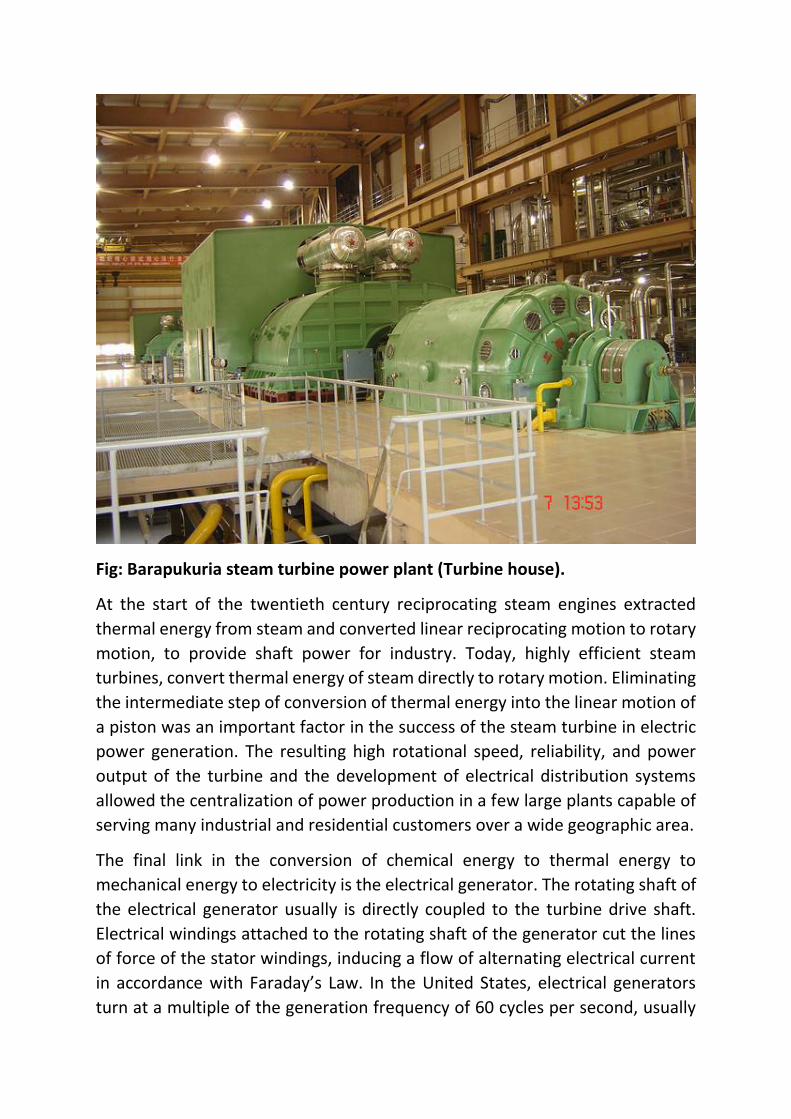
Fig: Barapukuria steam turbine power plant (Turbine house).
At the start of the twentieth century reciprocating steam engines extracted
thermal energy from steam and converted linear reciprocating motion to rotary
motion, to provide shaft power for industry. Today, highly efficient steam
turbines, convert thermal energy of steam directly to rotary motion. Eliminating
the intermediate step of conversion of thermal energy into the linear motion of
a piston was an important factor in the success of the steam turbine in electric
power generation. The resulting high rotational speed, reliability, and power
output of the turbine and the development of electrical distribution systems
allowed the centralization of power production in a few large plants capable of
serving many industrial and residential customers over a wide geographic area.
The final link in the conversion of chemical energy to thermal energy to
mechanical energy to electricity is the electrical generator. The rotating shaft of
the electrical generator usually is directly coupled to the turbine drive shaft.
Electrical windings attached to the rotating shaft of the generator cut the lines
of force of the stator windings, inducing a flow of alternating electrical current
in accordance with Faraday’s Law. In the United States, electrical generators
turn at a multiple of the generation frequency of 60 cycles per second, usually
1800 or 3600 rpm. Elsewhere, where 50 cycles per second is the standard
frequency, the speed of 3000 rpm is common.
Through transformers at the power plant, the voltage is increased to several
hundred thousand volts for transmission to distant distribution centers. At the
distribution centers as well as neighborhood electrical transformers, the
electrical potential is reduced, ultimately to the 110- and 220-volt levels used in
homes and industry.
Since at present there is no economical way to store the large quantities of
electricity produced by a power plant, the generating system must adapt, from
moment to moment, to the varying demands for electricity from its customers.
It is therefore important that a power company have both sufficient generation
capacity to reliably satisfy the maximum demand and generation equipment
capable of adapting to varying load.
3. Description of Steam Power Plant:
Basic Steam Plant consists of a:
a. Boiler
b. Steam Turbine
c. Condenser
d. Feed pump
e. Economizer
f. Pre-heater
3.1 Boiler:
The purpose of the boiler is to convert water (pumped into it under pressure) to
steam. The steam may emerge wet, dry saturated, or superheated depending
on the boiler design. Thermal electrical power generation is one of the major
methods. For a thermal power plant the range of pressure may vary from 10
kg/cm2 to super critical pressures and the range of temperature may be from
250°C to 650°C.
3.1.1 Essentials of Steam Power Plant Equipment:
A steam power plant must have following equipment:
(a) A furnace to burn the fuel.
(b) Boiler or boiler containing water. Heat generated in the furnace is utilized
to convert water into steam.
(c) Main power unit such as a turbine to use the heat energy of steam and
perform work.
(d) Piping system to convey steam and water.
In addition to the above equipment the plant requires various auxiliaries and
accessories depending upon the availability of water, fuel and the service for
which the plant is intended.
The flow sheet of a thermal power plant consists of the following four main
circuits:
(a) Feed water and steam flow circuit.
(b) Coal and ash circuit.
(c) Air and gas circuit.
(d) Cooling water circuit.
A steam power plant using steam as working substance works basically on
Rankine cycle.
Steam is generated in a boiler, expanded in the prime mover and condensed in
the condenser and fed into the boiler again.
The different types of systems and components used in steam power plant are
as follows:
(a) High pressure boiler
(b) Prime mover
(c) Condensers and cooling towers
(d) Coal handling system
(e) Ash and dust handling system
(f) Draught system
(g) Feed water purification plant
(h) Pumping system
(i) Air preheater, economizer, super heater, feed heaters.
Figure 2.11 shows a schematic arrangement of equipment of a steam power
station. Coal received in coal storage yard of power station is transferred in the
furnace by coal handling unit. Heat produced due to burning of coal is utilized in
converting water contained in boiler drum into steam at suitable pressure and
temperature. The steam generated is passed through the super heater.
Superheated steam then flows through the turbine. After doing work in the
turbine the pressure of steam is reduced. Steam leaving the turbine passes

through the condenser which is maintained the low pressure of steam at the
exhaust of turbine. Steam pressure in the condenser depends upon flow rate
and temperature of cooling water and on effectiveness of air removal
equipment. Water circulating through the condenser may be taken from the
various sources such as river, lake or sea. If sufficient quantity of water is not
available the hot water coming out of the condenser may be cooled in cooling
towers and circulated again through the condenser. Bled steam taken from the
turbine at suitable extraction points is sent to low pressure and high pressure
water heaters.
Air taken from the atmosphere is first passed through the air pre-heater, where
it is heated by flue gases. The hot air then passes through the furnace. The flue
gases after passing over boiler and super heater tubes, flow through the dust
collector and then through economizer, air pre-heater and finally they are
exhausted to the atmosphere through the chimney.
Steam condensing system consists of the following:
(a) Condenser
(b) Cooling water
(c) Cooling tower
(d) Hot well
(e) Condenser cooling water pump
(f) Condensate air extraction pump
(g) Air extraction pump
(h) Boiler feed pump
(i) Make up water pump.
3.1.2 Steam production:
Boiler is an apparatus to produce steam. Thermal energy released by
combustion of fuel is transferred to water, which vaporizes and gets converted
into steam at the desired temperature and pressure.
The steam produced is used for:
(a) Producing mechanical work by expanding it in steam engine or steam
turbine.
(b) Heating the residential and industrial buildings.
(c) Performing certain processes in the sugar mills, chemical and textile
industries.
Boiler is a closed vessel in which water is converted into steam by the application
of heat. Usually boilers are coal or oil fired.
3.1.3 Types of Boilers
The boilers can be classified according to the following criteria. According to flow
of water and hot gases:
(a) Water tube
(b) Fire tube.
In water tube boilers, water circulates through the tubes and hot products of
combustion flow over these tubes. In fire tube boiler the hot products of
combustion pass through the tubes, which are surrounded, by water. Fire tube
boilers have low initial cost, and are more compacts. But they are more likely to
explosion, water volume is large and due to poor circulation they cannot meet
quickly the change in steam demand. For the same output the outer shell of fire
tube boilers is much larger than the shell of water-tube boiler.
Water tube boilers require less weight of metal for a given size, are less liable to
explosion, produce higher pressure, are accessible and can respond quickly to
change in steam demand. Tubes and drums of water-tube boilers are smaller
than that of fire-tube boilers and due to smaller size of drum higher pressure
can be used easily. Water-tube boilers require lesser floor space. The efficiency
of water-tube boilers is more.
Water tube boilers are classified as follows:
Horizontal Straight Tube Boilers
(a) Longitudinal drum
(b) Cross-drum.
Bent Tube Boilers
(a) Two drum
(b) Three drum
(c) Low head three drum
(d) Four drum.
(e) Cyclone Fired Boilers
Various advantages of water tube boilers are as follows:
(a) High pressure can be obtained.
(b) Heating surface is large. Therefore steam can be generated easily.
(c) Large heating surface can be obtained by use of large number of tubes.
(d) Because of high movement of water in the tubes the rate of heat transfer
becomes large resulting into a greater efficiency.
Fire tube boilers are classified as follows:
External Furnace
(a) Horizontal return tubular
(b) Short fire box
(c) Compact.
Internal Furnace
Horizontal Tubular
(a) Short firebox
(b) Locomotive
(c) Compact
(d) Scotch.
Vertical Tubular
(a) Straight vertical shell, vertical tube
(b) Cochran (vertical shell) horizontal tube.
Various advantages of fire tube boilers are as follows:
(a) Low cost
(b) Fluctuations of steam demand can be met easily
(c) It is compact in size.
According to position of furnace:
(a) Internally fired
(b) Externally fired
In internally fired boilers the grate combustion chamber are enclosed within the
boiler shell whereas in case of extremely fired boilers and furnace and grate are
separated from the boiler shell.
According to the position of principle axis:
(a) Vertical
(b) Horizontal
(c) Inclined.
According to application:
(a) Stationary
(b) Mobile, (Marine, Locomotive).
According to the circulating water:
(a) Natural circulation
(b) Forced circulation.
According to steam pressure:
(a) Low pressure
(b) Medium pressure
(c) Higher pressure.
3.1.4 Major Components of Steam Power Plant and Their Functions
Economizer
The economizer is a feed water heater, deriving heat from the flue gases. The
justifiable cost of the economizer depends on the total gain in efficiency. In turn
this depends on the flue gas temperature leaving the boiler and the feed water
inlet temperature. A typical return bend type economizer is shown in the Figure.
Air Pre-heater
The flue gases coming out of the economizer is used to preheat the air before
supplying it to the combustion chamber. An increase in air temperature of 20
degrees can be achieved by this method. The pre heated air is used for
combustion and also to dry the crushed coal before pulverizing.
Soot Blowers
The fuel used in thermal power plants causes soot and this is deposited on the
boiler tubes, economizer tubes, air pre heaters, etc. This drastically reduces the
amount of heat transfer of the heat exchangers. Soot blowers control the
formation of soot and reduce its corrosive effects. The types of soot blowers are
fixed type, which may be further classified into lane type and mass type
depending upon the type of spray and nozzle used. The other type of soot
blower is the retractable soot blower. The advantages are that they are placed
far away from the high temperature zone, they concentrate the cleaning
through a single large nozzle rather than many small nozzles and there is no
concern of nozzle arrangement with respect to the boiler tubes.
Condenser
The use of a condenser in a power plant is to improve the efficiency of the power
plant by decreasing the exhaust pressure of the steam below atmosphere.
Another advantage of the condenser is that the steam condensed may be
recovered to provide a source of good pure feed water to the boiler and reduce
the water softening capacity to a considerable extent. A condenser is one of the
essential components of a power plant.
Cooling Tower
The importance of the cooling tower is felt when the cooling water from the
condenser has to be cooled. The cooling water after condensing the steam
becomes hot and it has to be cooled as it belongs to a closed system. The Cooling
towers do the job of decreasing the temperature of the cooling water after
condensing the steam in the condenser.
The type of cooling tower used in the Columbia Power Plant was an Inline
Induced Draft Cross Flow Tower. This tower provides a horizontal air flow as the
water falls down the tower in the form of small droplets. The fan centered at
the top of units draws air through two cells that are paired to a suction chamber
partitioned beneath the fan. The outstanding feature of this tower is lower air
static pressure loss as there is less resistance to air flow. The evaporation and
effective cooling of air is greater when the air outside is warmer and dryer than
when it is cold and already saturated.
Superheater
The superheater consists of a superheater header and superheater elements.
Steam from the main steam pipe arrives at the saturated steam chamber of the
superheater header and is fed into the superheater elements. Superheated
steam arrives back at the superheated steam chamber of the superheater
header and is fed into the steam pipe to the cylinders. Superheated steam is
more expansive.
Reheater
The reheater functions similar to the superheater in that it serves to elevate the
steam temperature. Primary steam is supplied to the high pressure turbine.
After passing through the high pressure turbine, the steam is returned to the
boiler for reheating (in a reheater) after which it is sent to the low pressure
turbine. A second reheat cycle may also be provided.
3.2 SUPER HEATER:
One of the most important accessories of a boiler is a super heater. It effects
improvement and economy in the following ways:
a) The super heater increases the capacity of the plant.
b) Eliminates corrosion of the steam turbine.
c) Reduces steam consumption of the steam turbine.
3.2.1 Types of Super Heater
(a) Plate Super heaters.
(b) Pendant Super heaters.
(c) Radiant Super heaters.
(d) Final Super heaters.
3.2.2 Steam Temperature Control
The nominal control of reheat steam temperature is by tilting the burners. The
super heater steam temperature is controlled by spraying water.
Other control methods that are according to the need and design are:
(a) Excess Air Control
(b) Flue Gas Recirculation
(c) Gas by-pass Control
(d) Control of Combination Superheaters
(e) Adjustable Burner Control
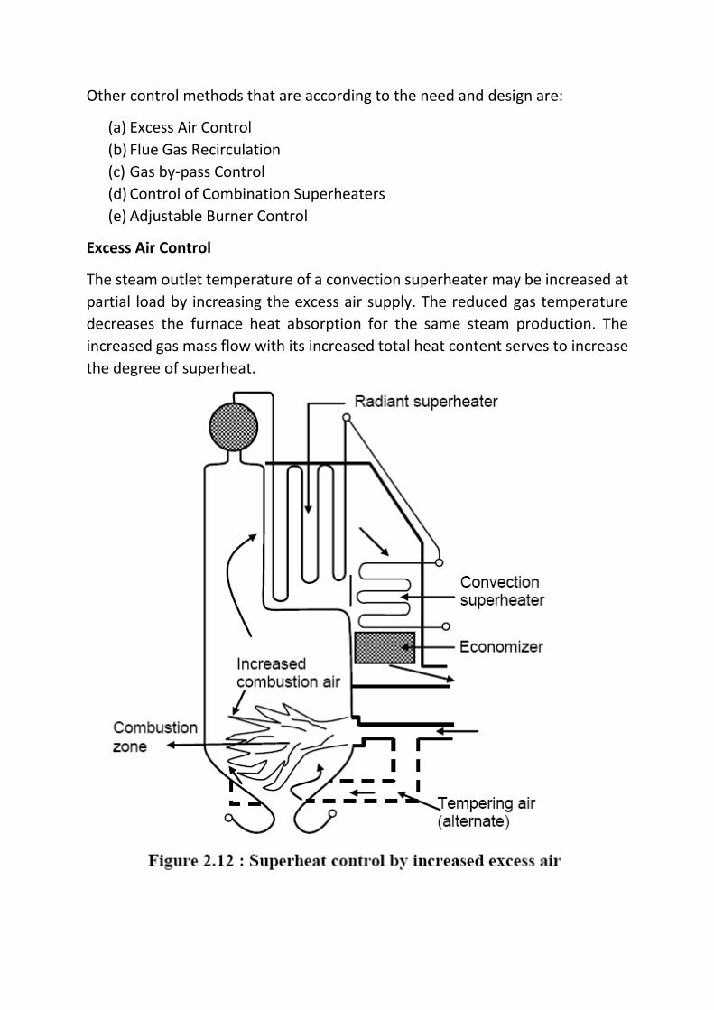
Excess Air Control
The steam outlet temperature of a convection superheater may be increased at
partial load by increasing the excess air supply. The reduced gas temperature
decreases the furnace heat absorption for the same steam production. The
increased gas mass flow with its increased total heat content serves to increase
the degree of superheat.
Flue Gas Recirculation
The recirculation of some percentage of the combustion gases serves to control
steam temperature in the same manner as does an increase in excess air. By
introducing the hot gases below the combustion zone, relatively high efficiency
may be maintained.
Gas By-pass Control
The boiler convection banks can be arranged in such a manner that portion of
the gases can be by-passed around the superheater elements. The superheater
is oversized so that it will produce the required degree of superheat at partial
load conditions. As the load increases, some of the flue gases are by-passed.
Control of Combination Superheaters
The control of combination radiant-convection superheaters is relatively simple
because of their compensating characteristics. An increase in excess air reduces
the radiant heat transfer but increases the convection heat transfer. The
reduction in excess air has the opposite effect. Thus the combination
superheaters can be operated over the entire control range without additional
equipment.
Adjustable Burner Control
With a multiple burner furnace it is possible to distribute the burners over a
considerable burner wall height. This control is obtained by selective firing.
Tiltable furnace may be adjusted to shift the position of the combustion zone.
3.3 FEED WATER HEATER
Low pressure feed water heaters are used in the condensate system between
the condensate pump discharge and boiler feed pumps, and utilize low pressure
turbine extraction or auxiliary turbine exhaust steam for heating the
condensate.
High pressure feed water heaters are used in the feed water system between
the boiler feed pump discharge and the boiler, and utilize high pressure turbine
extraction steam for heating the feed water. The condensate or feed water
temperature increase for each feed water heater will be in the range of 28 to 56
degrees C with the actual value determined by turbine manufacturer`s stage
location of steam extraction nozzles. Depending on turbine size, some turbines
offer alternate number of extraction nozzles with usually a choice of using the
highest pressure extraction nozzle. The selection, in this case, of the total
number of feed water heaters to use should be based on economic evaluation.
Low Pressure Heater(s)
Use one or more low pressure feed water heaters to raise the temperature of
condensate from condensate pump discharge temperature to the de-aerator
inlet temperature. The heater drains are cascaded from the higher pressure
heater to the next lower pressure heater with the lowest pressure heater
draining to the condenser.
High Pressure Heater(s)
Use one or more high pressure feed water heaters to raise the temperature of
feed water from de-aerator outlet temperature to the required boiler
economizer inlet temperature. The heater drains are cascaded from heater to
heater, back to the de-aerator in a fashion similar to the heater drain system for
the low pressure heaters.
Advantages
(a) Fuel economy.
(b) Longer life of the boiler.
(c) Increase in steaming capacity.
A feedwater heater is a power plant component used to pre-heat water
delivered to a steam generating boiler. Preheating the feedwater reduces the
irreversibilities involved in steam generation and therefore improves the
thermodynamic efficiency of the system. This reduces plant operating costs and
also helps to avoid thermal shock to the boiler metal when the feedwater is
introduced back into the steam cycle.
In a steam power plant (usually modeled as a modified Rankine cycle),
feedwater heaters allow the feedwater to be brought up to the saturation
temperature very gradually. This minimizes the inevitable irreversibilities
associated with heat transfer to the working fluid (water).
3.4 STEAM TURBINES
A steam turbine is a mechanical device that extracts thermal energy from
pressurized steam, and converts it into rotary motion. It has almost completely
replaced the reciprocating piston steam engine primarily because of its greater
thermal efficiency and higher power-to-weight ratio. Because the turbine
generates rotary motion, it is particularly suited to be used to drive an electrical
generator – about 80% of all electricity generation in the world is by use of steam
turbines. The steam turbine is a form of heat engine that derives much of its
improvement in thermodynamic efficiency through the use of multiple stages in
the expansion of the steam, which results in a closer approach to the ideal
reversible process.
3.4.1 Types
Steam turbines are made in a variety of sizes ranging from small 0.75 kW units
(rare) used as mechanical drives for pumps, compressors and other shaft driven
equipment, to 1,500,000 kW turbines used to generate electricity. There are
several classifications for modern steam turbines.
3.4.2 Steam Turbine Classification
Steam Turbines have been classified by:
(i) Details of stage design as
(a) impulse
(b) reaction
(ii) Steam supply and exhaust conditions as:
(a) Condensing
(b) Back Pressure (Non Condensing)
(c) Mixed Pressure
(d) Reheat
(e) Extraction type (Auto or Controlled)
(iii) Casing or shaft arrangement as:
(a) Single Casing
(b) Tandem compound
(c) Cross Compound
Condensing turbines are most commonly found in electrical power plants. These
turbines exhaust steam in a partially condensed state, typically of a quality near
90%, at a pressure well below atmospheric to a condenser.
Non-condensing or backpressure turbines are most widely used for process
steam applications. The exhaust pressure is controlled by a regulating valve to
suit the needs of the process steam pressure. These are commonly found at
refineries, district heating units, pulp and paper plants, and desalination
facilities where large amounts of low pressure process steam are available.
Reheat turbines are also used almost exclusively in electrical power plants. In a
reheat turbine, steam flow exits from a high pressure section of the turbine and
is returned to the boiler where additional superheat is added. The steam then
goes back into an intermediate pressure section of the turbine and continues its
expansion.
Extracting type turbines are common in all applications. In an extracting type
turbine, steam is released from various stages of the turbine, and used for
industrial process needs or sent to boiler feedwater heaters to improve overall
cycle efficiency. Extraction flows may be controlled with a valve, or left
uncontrolled.
Induction turbines introduce low pressure steam at an intermediate stage to
produce additional power.
Single casing units are the most basic style where a single casing and shaft are
coupled to a generator. Tandem compound are used where two or more casings
are directly coupled together to drive a single generator. A cross compound
turbine arrangement features two or more shafts not in line driving two or more
generators that often operate at different speeds. A cross compound turbine is
typically used for many large applications.
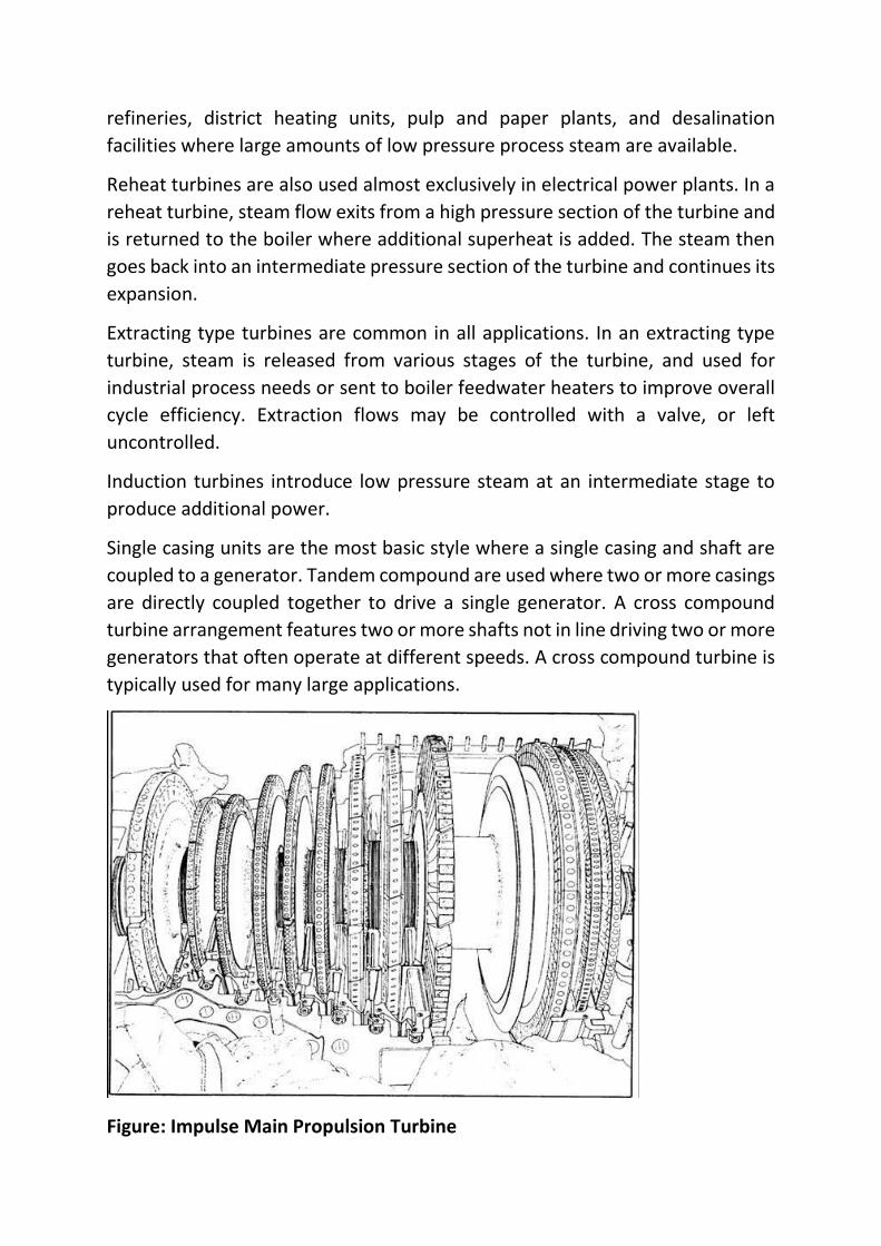
Figure: Impulse Main Propulsion Turbine
(iv) Number of Exhaust Stages in Parallel
(v) Direction of steam flow
(vi) Steam supply – Superheated or saturated.
3.4.3 Principle of Operation and Design
An ideal steam turbine is considered to be an isentropic process, or constant
entropy process, in which the entropy of the steam entering the turbine is equal
to the entropy of the steam leaving the turbine. No steam turbine is truly
“isentropic”, however, with typical isentropic efficiencies ranging from 20%-90%
based on the application of the turbine. The interior of a turbine comprises
several sets of blades, or “buckets” as they are more commonly referred to. One
set of stationary blades is connected to the casing and one set of rotating blades
is connected to the shaft. The sets intermesh with certain minimum clearances,
with the size and configuration of sets varying to efficiently exploit the
expansion of steam at each stage.
3.4.4 Turbine Efficiency
To maximize turbine efficiency the steam is expanded, generating work, in a
number of stages. These stages are characterized by how the energy is extracted
from them and are known as either impulse or reaction turbines. Most steam
turbines use a mixture of the reaction and impulse designs each stage behaves
as either one or the other, but the overall turbine uses both. Typically, higher
pressure sections are impulse type and lower pressure stages are reaction type.
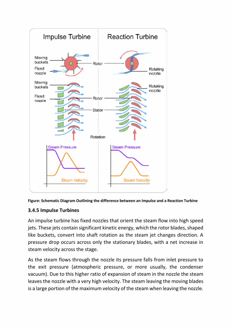
Figure: Schematic Diagram Outlining the difference between an Impulse and a Reaction Turbine
3.4.5 Impulse Turbines
An impulse turbine has fixed nozzles that orient the steam flow into high speed
jets. These jets contain significant kinetic energy, which the rotor blades, shaped
like buckets, convert into shaft rotation as the steam jet changes direction. A
pressure drop occurs across only the stationary blades, with a net increase in
steam velocity across the stage.
As the steam flows through the nozzle its pressure falls from inlet pressure to
the exit pressure (atmospheric pressure, or more usually, the condenser
vacuum). Due to this higher ratio of expansion of steam in the nozzle the steam
leaves the nozzle with a very high velocity. The steam leaving the moving blades
is a large portion of the maximum velocity of the steam when leaving the nozzle.
The loss of energy due to this higher exit velocity is commonly called the “carry
over velocity” or “leaving loss”.
3.4.6 Reaction Turbines
In the reaction turbine, the rotor blades themselves are arranged to form
convergent nozzles. This type of turbine makes use of the reaction force
produced as the steam accelerates through the nozzles formed by the rotor.
Steam is directed onto the rotor by the fixed vanes of the stator. It leaves the
stator as a jet that fills the entire circumference of the rotor. The steam then
changes direction and increases its speed relative to the speed of the blades. A
pressure drop occurs across both the stator and the rotor, with steam
accelerating through the stator and decelerating through the rotor, with no net
change in steam velocity across the stage but with a decrease in both pressure
and temperature, reflecting the work performed in the driving of the rotor.
3.5 CONDENSER
3.5.1 Functions of Condensers
The main purposes of the condenser are to condense the exhaust steam from
the turbine for reuse in the cycle and to maximize turbine efficiency by
maintaining proper vacuum. As the operating pressure of the condenser is
lowered (vacuum is increased), the enthalpy drop of the expanding steam in the
turbine will also increase. This will increase the amount of available work from
the turbine (electrical output). By lowering the condenser operating pressure,
the following will occur:
(a) Increased turbine output
(b) Increased plant efficiency
(c) Reduced steam flow (for a given plant output)
It is therefore very advantageous to operate the condenser at the lowest
possible pressure (highest vacuum).
3.5.2 Condenser Types
There are two primary types of condensers that can be used in a power plant:
(a) Direct Contact
(b) Surface
Direct contact condensers condense the turbine exhaust steam by mixing it
directly with cooling water. The older type Barometric and Jet-Type condensers
operate on similar principles.
Steam surface condensers are the most commonly used condensers in modern
power plants. The exhaust steam from the turbine flows on the shell side (under
vacuum) of the condenser, while the plant’s circulating water flows in the tube
side. The source of the circulating water can be either a closed-loop (i.e. cooling
tower, spray pond, etc.) or once through (i.e. from a lake, ocean, or river). The
condensed steam from the turbine, called condensate, is collected in the bottom
of the condenser, which is called a hotwell. The condensate is then pumped back
to the boiler to repeat the cycle.
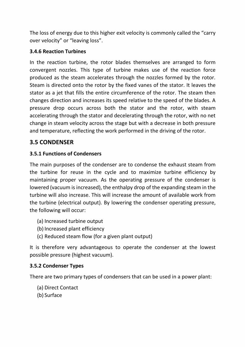
3.5.3 Surface Condenser
The surface condenser is a shell and tube heat exchanger in which cooling water
is circulated through the tubes. The exhaust steam from the low pressure
turbine enters the shell where it is cooled and converted to condensate (water)
by flowing over the tubes as shown in the diagram. Such condensers use steam
ejectors or rotary motor-driven exhausters for continuous removal of air and
gases from the steam side to maintain vacuum.
Figure: Diagram of a Typical Water-cooled Surface Condenser
For best efficiency, the temperature in the condenser must be kept as low as
practical in order to achieve the lowest possible pressure in the condensing
steam. Since the condenser temperature can almost always be kept significantly
below 100oC where the vapor pressure of water is much less than atmospheric
pressure, the condenser generally works under vacuum. Thus leaks of non-
condensable air into the closed loop must be prevented.
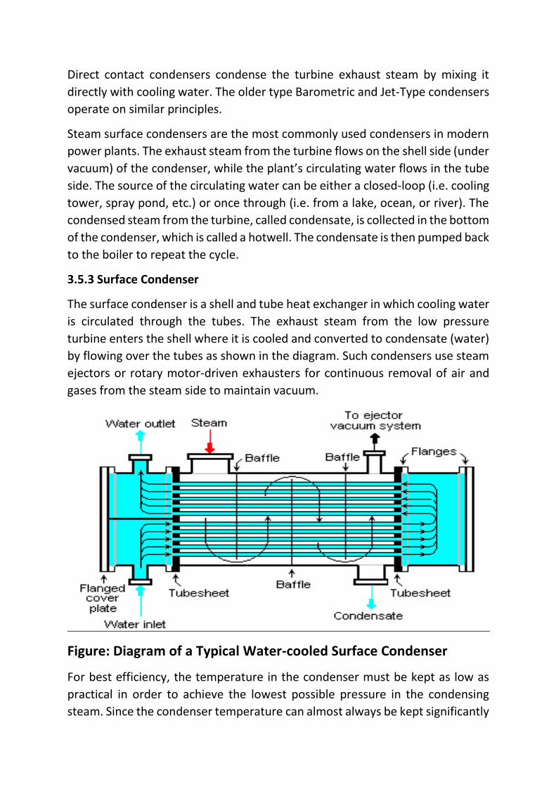
The condenser generally uses either circulating cooling water from a cooling
tower to reject waste heat to the atmosphere, or once-through water from a
river, lake or ocean.
Figure: Typical Power Plant Condenser
The diagram depicts a typical water-cooled surface condenser as used in power
stations to condense the exhaust steam from a steam turbine driving an
electrical generator as well in other applications.
3.6 COOLING TOWER
3.6.1 Cooling Tower
A cooling tower extracts heat from water by evaporation. In an evaporative
cooling tower, a small portion of the water being cooled is allowed to evaporate
into a moving air stream to provide significant cooling to the rest of that water
stream.
Cooling Towers are commonly used to provide lower than ambient water
temperatures and are more cost effective and energy efficient than most other
alternatives. The smallest cooling towers are structured for only a few litres of
water per minute while the largest cooling towers may handle upwards of
thousands of litres per minute. The pipes are obviously much larger to
accommodate this much water in the larger towers and can range up to 12
inches in diameter.
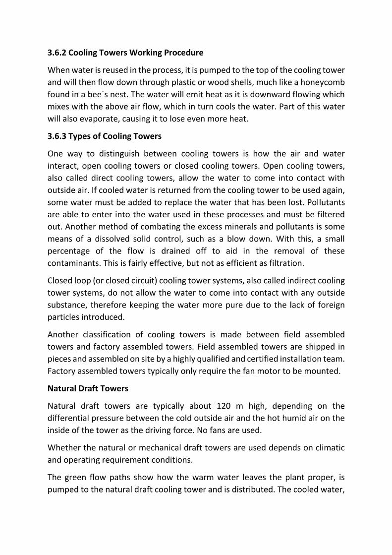
3.6.2 Cooling Towers Working Procedure
When water is reused in the process, it is pumped to the top of the cooling tower
and will then flow down through plastic or wood shells, much like a honeycomb
found in a bee`s nest. The water will emit heat as it is downward flowing which
mixes with the above air flow, which in turn cools the water. Part of this water
will also evaporate, causing it to lose even more heat.
3.6.3 Types of Cooling Towers
One way to distinguish between cooling towers is how the air and water
interact, open cooling towers or closed cooling towers. Open cooling towers,
also called direct cooling towers, allow the water to come into contact with
outside air. If cooled water is returned from the cooling tower to be used again,
some water must be added to replace the water that has been lost. Pollutants
are able to enter into the water used in these processes and must be filtered
out. Another method of combating the excess minerals and pollutants is some
means of a dissolved solid control, such as a blow down. With this, a small
percentage of the flow is drained off to aid in the removal of these
contaminants. This is fairly effective, but not as efficient as filtration.
Closed loop (or closed circuit) cooling tower systems, also called indirect cooling
tower systems, do not allow the water to come into contact with any outside
substance, therefore keeping the water more pure due to the lack of foreign
particles introduced.
Another classification of cooling towers is made between field assembled
towers and factory assembled towers. Field assembled towers are shipped in
pieces and assembled on site by a highly qualified and certified installation team.
Factory assembled towers typically only require the fan motor to be mounted.
Natural Draft Towers
Natural draft towers are typically about 120 m high, depending on the
differential pressure between the cold outside air and the hot humid air on the
inside of the tower as the driving force. No fans are used.
Whether the natural or mechanical draft towers are used depends on climatic
and operating requirement conditions.
The green flow paths show how the warm water leaves the plant proper, is
pumped to the natural draft cooling tower and is distributed. The cooled water,
including makeup from the lake to account for evaporation losses to the
atmosphere, is returned to the condenser.
Mechanical Draft
Mechanical draft towers uses fans (one or more) to move large quantities of air
through the tower. They are two different classes:
(a) Forced draft cooling towers
(b) Induced draft cooling towers
The air flow in either class may be cross flow or counter flow with respect to the
falling water. Cross flow indicates that the airflow is horizontal in the filled
portion of the tower while counter flow means the air flow is in the opposite
direction of the falling water.
The counter flow tower occupies less floor space than a cross flow tower but is
taller for a given capacity. The principle advantages of the cross flow tower are
the low pressure drop in relation to its capacity and lower fan power
requirement leading to lower energy costs.
All mechanical towers must be located so that the discharge air diffuses freely
without recirculation through the tower, and so that air intakes are not
restricted. Cooling towers should be located as near as possible to the
refrigeration systems they serve, but should never be located below them so as
to allow the condenser water to drain out of the system through the tower basin
when the system is shut down.
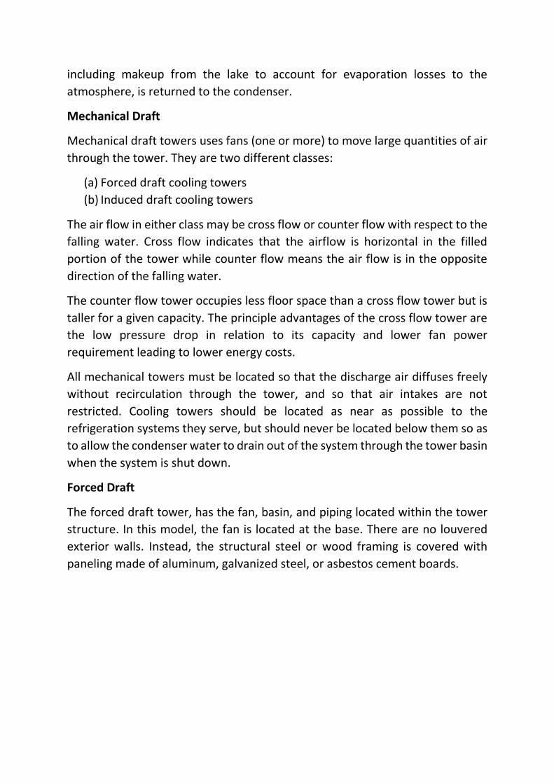
Forced Draft
The forced draft tower, has the fan, basin, and piping located within the tower
structure. In this model, the fan is located at the base. There are no louvered
exterior walls. Instead, the structural steel or wood framing is covered with
paneling made of aluminum, galvanized steel, or asbestos cement boards.
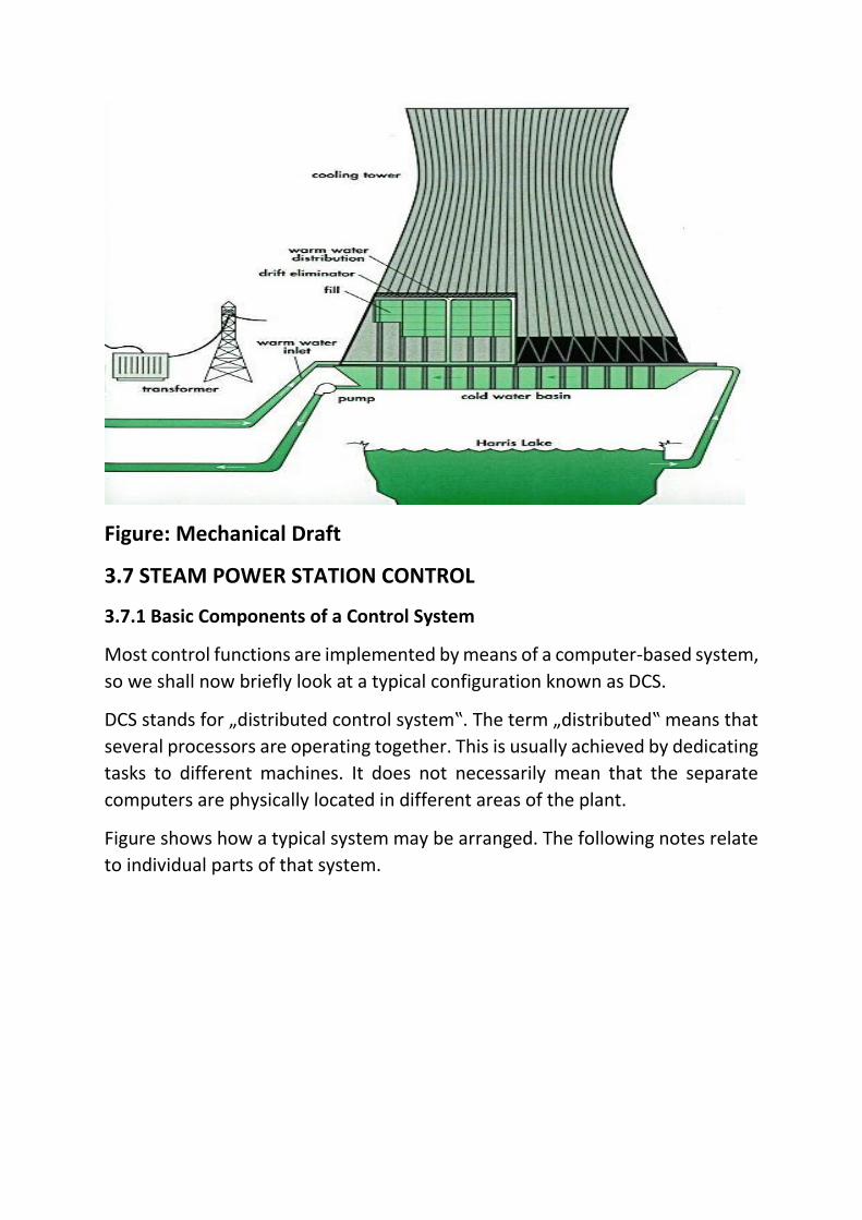
Figure: Mechanical Draft
3.7 STEAM POWER STATION CONTROL
3.7.1 Basic Components of a Control System
Most control functions are implemented by means of a computer-based system,
so we shall now briefly look at a typical configuration known as DCS.
DCS stands for „distributed control system‟. The term „distributed‟ means that
several processors are operating together. This is usually achieved by dedicating
tasks to different machines. It does not necessarily mean that the separate
computers are physically located in different areas of the plant.
Figure shows how a typical system may be arranged. The following notes relate
to individual parts of that system.
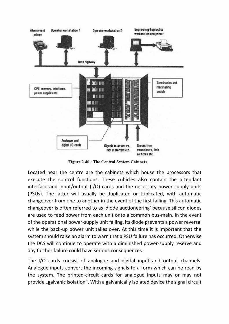
Located near the centre are the cabinets which house the processors that
execute the control functions. These cubicles also contain the attendant
interface and input/output (I/O) cards and the necessary power supply units
(PSUs). The latter will usually be duplicated or triplicated, with automatic
changeover from one to another in the event of the first failing. This automatic
changeover is often referred to as 'diode auctioneering' because silicon diodes
are used to feed power from each unit onto a common bus-main. In the event
of the operational power-supply unit failing, its diode prevents a power reversal
while the back-up power unit takes over. At this time it is important that the
system should raise an alarm to warn that a PSU failure has occurred. Otherwise
the DCS will continue to operate with a diminished power-supply reserve and
any further failure could have serious consequences.
The I/O cards consist of analogue and digital input and output channels.
Analogue inputs convert the incoming signals to a form which can be read by
the system. The printed-circuit cards for analogue inputs may or may not
provide „galvanic isolation‟. With a galvanically isolated device the signal circuit
is electrically isolated from others, from the system earth and from the power-
supply common rail.
Termination and Marshalling
It is important to understand that the grouping of inputs and outputs on the I/O
cards does not always correspond with the grouping of signals into multipair
cables, which is dictated by the physical arrangement of equipment on the plant.
While it is sensible to avoid mixing different control systems (e.g. feed water
control and combustion control) onto a single card, the signals associated with
a single system will not necessarily all be carried in the same cable. The result is
that a certain degree of cross connection or 'marshalling' is always required.
Operator Workstations
The operator workstations consist of screens on which plant information can be
observed, plus keyboards, trackballs or „mouse‟ devices allowing the operator
to send commands to the system. They also comprise printers for operational
records, logging of events (such as start-up of a pump), or alarms. Some systems
also provide plotters
4. Steam power plant in Bangladesh:
Steam Turbine Plants is mainly based on natural gas. Also in some cases coal and
furnace oil are used as primary fuel in small amount. The largest steam turbine
power plant based on natural gas is situated at Ghorasal, Narsingdi. There are
six numbers of units (per units 55 and 210 MW) having capacity (55x2+210x4)
950 MW. Installation of 200-300 MW capacity duel fuel plants at the existing
Ghorasal premises is under process.
The only coal fired steam power plant of Bangladesh is situated in the district of
Dinajpur at Barapukuria. There are two units of having capacity 125 MW each
i.e. total capacity of 250 MW. The Barapukuria coal base power plant is using
domestic high quality coal. Installation of another coal base power plant unit of
125 MW at the same premises is also under process.
Barapukuria Power Station is located to the west of, and adjacent to, the
Barapukuria Coal Mine. Its generating capacity will be 2 x 125 megawatt (MW)
of electricity. Approximately 900 L/s (77 ML/day) of water will be required for
cooling. Groundwater will be extracted from 14 production tubewells to the
north of the site.
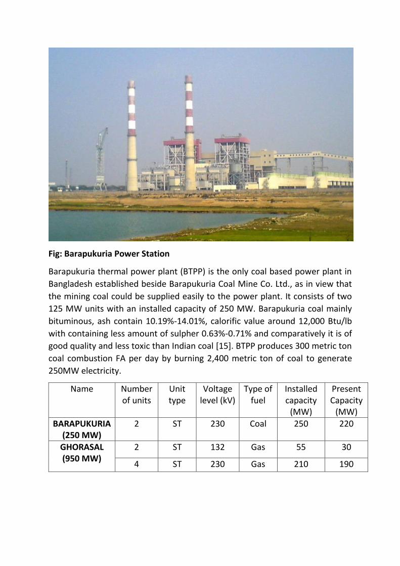
Fig: Barapukuria Power Station
Barapukuria thermal power plant (BTPP) is the only coal based power plant in
Bangladesh established beside Barapukuria Coal Mine Co. Ltd., as in view that
the mining coal could be supplied easily to the power plant. It consists of two
125 MW units with an installed capacity of 250 MW. Barapukuria coal mainly
bituminous, ash contain 10.19%-14.01%, calorific value around 12,000 Btu/lb
with containing less amount of sulpher 0.63%-0.71% and comparatively it is of
good quality and less toxic than Indian coal [15]. BTPP produces 300 metric ton
coal combustion FA per day by burning 2,400 metric ton of coal to generate
250MW electricity.
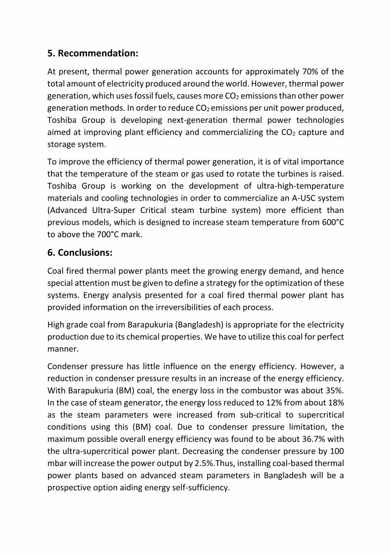
Name
Number of units
Unit type
Voltage level (kV)
Type of fuel
Installed capacity
(MW)
Present Capacity
(MW)
BARAPUKURIA (250 MW)
2 ST 230 Coal 250 220
GHORASAL (950 MW)
2 ST 132 Gas 55 30
4 ST 230 Gas 210 190
5. Recommendation:
At present, thermal power generation accounts for approximately 70% of the
total amount of electricity produced around the world. However, thermal power
generation, which uses fossil fuels, causes more CO2 emissions than other power
generation methods. In order to reduce CO2 emissions per unit power produced,
Toshiba Group is developing next-generation thermal power technologies
aimed at improving plant efficiency and commercializing the CO2 capture and
storage system.
To improve the efficiency of thermal power generation, it is of vital importance
that the temperature of the steam or gas used to rotate the turbines is raised.
Toshiba Group is working on the development of ultra-high-temperature
materials and cooling technologies in order to commercialize an A-USC system
(Advanced Ultra-Super Critical steam turbine system) more efficient than
previous models, which is designed to increase steam temperature from 600°C
to above the 700°C mark.
6. Conclusions:
Coal fired thermal power plants meet the growing energy demand, and hence
special attention must be given to define a strategy for the optimization of these
systems. Energy analysis presented for a coal fired thermal power plant has
provided information on the irreversibilities of each process.
High grade coal from Barapukuria (Bangladesh) is appropriate for the electricity
production due to its chemical properties. We have to utilize this coal for perfect
manner.
Condenser pressure has little influence on the energy efficiency. However, a
reduction in condenser pressure results in an increase of the energy efficiency.
With Barapukuria (BM) coal, the energy loss in the combustor was about 35%.
In the case of steam generator, the energy loss reduced to 12% from about 18%
as the steam parameters were increased from sub-critical to supercritical
conditions using this (BM) coal. Due to condenser pressure limitation, the
maximum possible overall energy efficiency was found to be about 36.7% with
the ultra-supercritical power plant. Decreasing the condenser pressure by 100
mbar will increase the power output by 2.5%.Thus, installing coal-based thermal
power plants based on advanced steam parameters in Bangladesh will be a
prospective option aiding energy self-sufficiency.
Related Documents