Independent Expert Engineering Investigation and Review Panel Report on Mount Polley Tailings Storage Facility Breach Appendix C: ATTACHMENTS Attachment C1: Laboratory Test Results Attachment C2: Block Sampling

Welcome message from author
This document is posted to help you gain knowledge. Please leave a comment to let me know what you think about it! Share it to your friends and learn new things together.
Transcript

Independent Expert Engineering Investigation and Review Panel
Report on Mount Polley Tailings Storage Facility Breach
Appendix C: ATTACHMENTS
Attachment C1: Laboratory Test Results
Attachment C2: Block Sampling
Independent Expert Engineering Investigation and Review Panel | January 30, 2015 | ATTACHMENT C 11
APPENDIX C: Surface Investigations Attachment C1
ATTACHMENT C1: LABORATORY TEST RESULTS
Laboratory testing on the grab samples collected during the field mapping and remnant till core excavation consisted
of classification and moisture content testing. Selected samples also underwent grain size analyses (GSA), and/or
Atterberg Limit testing. Where silt and clay fractions are separately reported, the GSA also included hydrometer testing.
Table 1 provides the results of laboratory testing.
TABLE 1. SURFACE INVESTIGATION LABORATORY TEST RESULTS
SAMPLE # DESCRIPTION UCS MC %GRAIN SIZE LIMITS
% GRAVEL % SAND % SILT % CLAY LL PL PI
Sa #1 Till Core SM/ML 7.0 9.5 38.2 39.7 12.6 - - -
Sa #2 Till SM/SC 8.8 10.2 37.2 34.6 18.0 - - -
Sa #3 Clayey Silt ML 38.8 0.0 0.5 72.6 26.9 42 29 13
Sa #4 Till CL/ML 9.2 8.0 30.4 43.7 17.9 - - -
Sa #5 Silt & Sand ML/SM 10.7 0.0 57.9 42.1 - - -
Sa #6 Sand SM 1.8 0.0 78.6 21.4 - - -
Sa #7 Till Core SC/SM 5.5 6.0 37.1 41.4 15.6 - - -
Sa #8 Gravel GP-GM 9.3 60.9 27.5 11.6 - - -
Sa #9 Clayey Silt ML 35.5 0.0 1.5 75.0 23.5 39 29 10
Sa #10 Silt & Sand ML/SM 15.9 0.0 58.4 41.6 - - -
Sa #11 Till SM/SC 6.7 13.6 36.0 34.5 15.9 - - -
Sa #12 Till CL/SC 6.9 22.1 32.1 31.6 14.2 - - -
Sa #13 Till CL/ML 4.7 11.4 34.8 39.1 14.6 - - -
Slice 4 Till Core (S) SC/CL 10.1 - - - - - - -
Slice 6 Till Core (S) SM 12.9 - - - - - - -
Slice 9 Till Core (S) SC/CL 11.8 - - - - - - -
Slice 14 Filter (F) GW-GM 7.1 51.4 37.6 11 - - -
Slice 14 Till Core (S) SC/CL 10.8 - - - - - - -
Slice 18 Filter (F) GW-GM 6.8 58.3 32 9.7 - - -
Slice 18 Sand SM 15.7 1 77.6 21.4 - - -
Slice 20 Till Core (S) CL 9 12.5 32.6 38.5 16.4 - - -
Slice 20 Filter (F) SM/GM 8.1 50.6 37.5 12 - - -
Slice 24 Gravel (Shear) GM 11.1 - - - - - - -
Slice 27 Till Core (S) CL 11.4 - - - - - - -
Slice 27 Till Core (S) SC/CL 10.3 - - - - - - -
Slice 31 Till Core (S) (U/S) CL 10.6 7.6 38.4 37.8 16.2 - - -
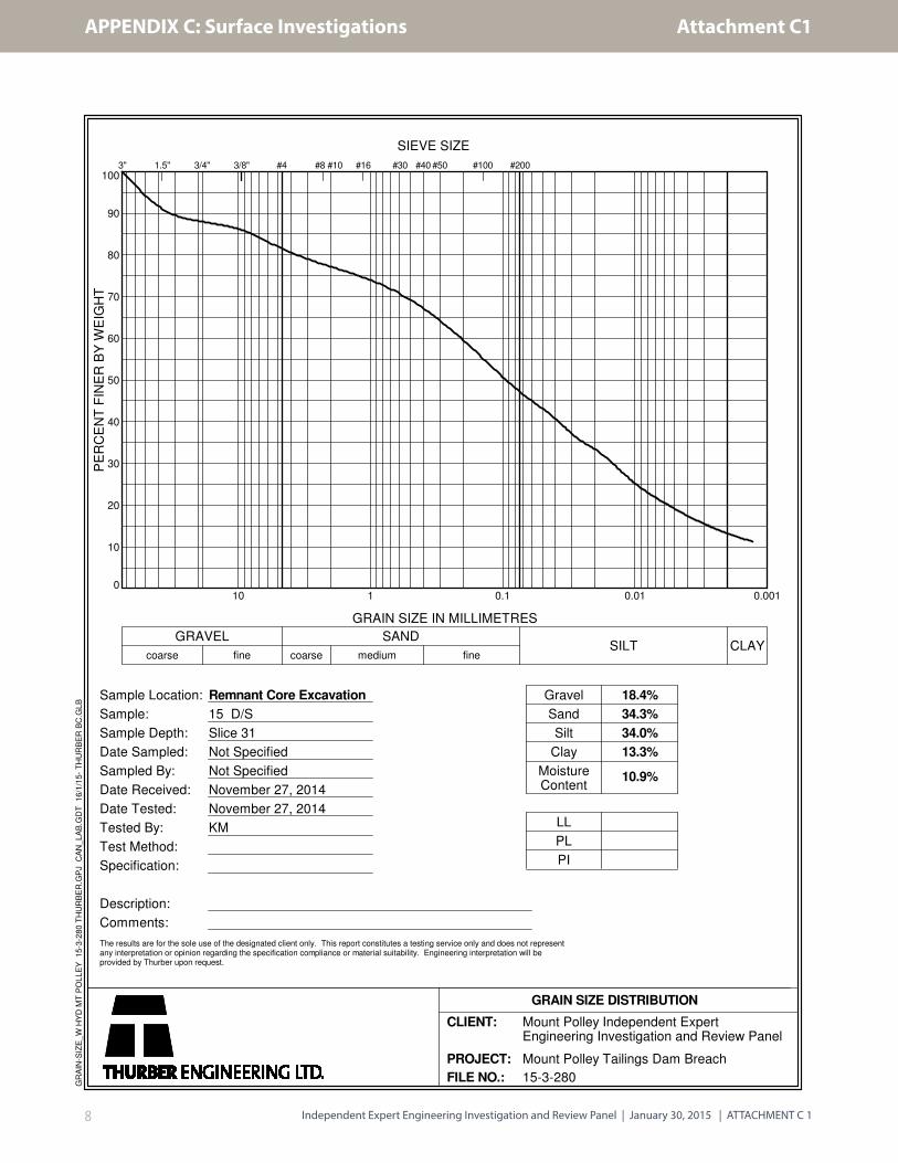
Slice 31 Till Core (S) (D/S) SC 10.9 18.4 34.3 34 13.3 - - -

Independent Expert Engineering Investigation and Review Panel | January 30, 2015 | ATTACHMENT C 12
APPENDIX C: Surface Investigations
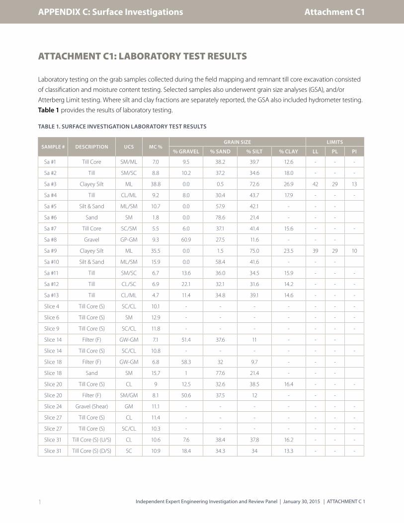
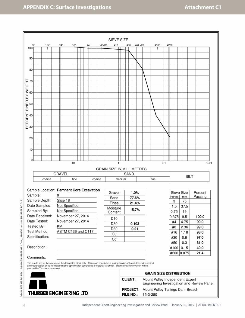
Gradation curves are shown on the following grain size plots. 1
1 MP00008
0
10
20
30
40
50
60
70
80
90
100
0.010.1110
3/8" #4 #30 #50 #2003" 3/4"1.5" #16 #40 #100
GRAIN SIZE IN MILLIMETRES
Sample Location:
Sample:
Sample Depth:
Date Sampled:
Sampled By:
Gravel
Fines
51.4%
37.6%
11.0%75
37.5
19
9.5
4.75
2.36
1.18
0.6
0.3
0.15
0.075
100.0
97.3
71.9
48.6
36.1
27.2
21.4
17.4
14.0
11.0
fine
#8#10
GRAIN SIZE DISTRIBUTION
SIEVE SIZE
GRAVELSILT
Date Received:
Date Tested:
Tested By:
Test Method:
Specification:
Description:
Comments:
Sand
7.1%
1.468
6.666
112.76
5.47
D10
D30
D60
Cu
Cc
Sieve Size PercentPassinginches
The results are for the sole use of the designated client only. This report constitutes a testing service only and does not representany interpretation or opinion regarding the specification compliance or material suitability. Engineering interpretation will beprovided by Thurber upon request.
mediumcoarse
mm
PE
RC
EN
T F
INE
R B
Y W
EIG
HT
SAND
MoistureContent
3
1.5
0.75
0.375
#4
#8
#16
#30
#50
#100
#200
finecoarse
November 27, 2014
November 27, 2014
KM
ASTM C136 and C117
Filter Sand Type B
Remnant Core Excavation
4
Slice 14
Not Specified
Not Specified
GR
AIN
SIZ
E M
T P
OL
LE
Y
15
-3-2
80
TH
UR
BE
R.G
PJ
CA
N_
LA
B.G
DT
1
6/1
/15
- T
HU
RB
ER
BC
.GL
B
CLIENT:
PROJECT:
FILE NO.: 15-3-280
Mount Polley Independent ExpertEngineering Investigation and Review Panel
Mount Polley Tailings Dam Breach
Attachment C1

Independent Expert Engineering Investigation and Review Panel | January 30, 2015 | ATTACHMENT C 13
APPENDIX C: Surface Investigations
0
10
20
30
40
50
60
70
80
90
100
0.010.1110
3/8" #4 #30 #50 #2003" 3/4"1.5" #16 #40 #100
GRAIN SIZE IN MILLIMETRES
Sample Location:
Sample:
Sample Depth:
Date Sampled:
Sampled By:
Gravel
Fines
58.3%
32.0%
9.7%75
37.5
19
9.5
4.75
2.36
1.18
0.6
0.3
0.15
0.075
100.0
96.9
64.0
41.7
30.7
23.4
19.0
15.7
12.6
9.7
fine
#8#10
GRAIN SIZE DISTRIBUTION
SIEVE SIZE
GRAVELSILT
Date Received:
Date Tested:
Tested By:
Test Method:
Specification:
Description:
Comments:
Sand
6.8%
0.08
2.208
8.39
104.59
7.24
D10
D30
D60
Cu
Cc
Sieve Size PercentPassinginches
The results are for the sole use of the designated client only. This report constitutes a testing service only and does not representany interpretation or opinion regarding the specification compliance or material suitability. Engineering interpretation will beprovided by Thurber upon request.
mediumcoarse
mm
PE
RC
EN
T F
INE
R B
Y W
EIG
HT
SAND
MoistureContent
3
1.5
0.75
0.375
#4
#8
#16
#30
#50
#100
#200
finecoarse
November 27, 2014
November 27, 2014
KM
ASTM C136 and C117
Filter Sand Type B
Remnant Core Excavation
7
Slice 18
Not Specified
Not Specified
GR
AIN
SIZ
E M
T P
OL
LE
Y
15
-3-2
80
TH
UR
BE
R.G
PJ
CA
N_
LA
B.G
DT
1
6/1
/15
- T
HU
RB
ER
BC
.GL
B
CLIENT:
PROJECT:
FILE NO.: 15-3-280
Mount Polley Independent ExpertEngineering Investigation and Review Panel
Mount Polley Tailings Dam Breach
Attachment C1
Independent Expert Engineering Investigation and Review Panel | January 30, 2015 | ATTACHMENT C 14
APPENDIX C: Surface Investigations
0
10
20
30
40
50
60
70
80
90
100
0.010.1110
3/8" #4 #30 #50 #2003" 3/4"1.5" #16 #40 #100
GRAIN SIZE IN MILLIMETRES
Sample Location:
Sample:
Sample Depth:
Date Sampled:
Sampled By:
Gravel
Fines
1.0%
77.6%
21.4%75
37.5
19
9.5
4.75
2.36
1.18
0.6
0.3
0.15
0.075
100.0
99.0
99.0
98.0
97.0
81.0
40.0
21.4
fine
#8#10
GRAIN SIZE DISTRIBUTION
SIEVE SIZE
GRAVELSILT
Date Received:
Date Tested:
Tested By:
Test Method:
Specification:
Description:
Comments:
Sand
15.7%
0.103
0.21
D10
D30
D60
Cu
Cc
Sieve Size PercentPassinginches
The results are for the sole use of the designated client only. This report constitutes a testing service only and does not representany interpretation or opinion regarding the specification compliance or material suitability. Engineering interpretation will beprovided by Thurber upon request.
mediumcoarse
mm
PE
RC
EN
T F
INE
R B
Y W
EIG
HT
SAND
MoistureContent
3
1.5
0.75
0.375
#4
#8
#16
#30
#50
#100
#200
finecoarse
November 27, 2014
November 27, 2014
KM
ASTM C136 and C117
Remnant Core Excavation
8
Slice 18
Not Specified
Not Specified
GR
AIN
SIZ
E M
T P
OL
LE
Y
15
-3-2
80
TH
UR
BE
R.G
PJ
CA
N_
LA
B.G
DT
1
6/1
/15
- T
HU
RB
ER
BC
.GL
B
CLIENT:
PROJECT:
FILE NO.: 15-3-280
Mount Polley Independent ExpertEngineering Investigation and Review Panel
Mount Polley Tailings Dam Breach
Attachment C1
Independent Expert Engineering Investigation and Review Panel | January 30, 2015 | ATTACHMENT C 15
APPENDIX C: Surface Investigations
0
10
20
30
40
50
60
70
80
90
100
0.010.1110
3/8" #4 #30 #50 #2003" 3/4"1.5" #16 #40 #100
GRAIN SIZE IN MILLIMETRES
Sample Location:
Sample:
Sample Depth:
Date Sampled:
Sampled By:
Gravel
Fines
50.6%
37.5%
12.0%75
37.5
19
9.5
4.75
2.36
1.18
0.6
0.3
0.15
0.075
100.0
99.1
73.5
49.4
37.6
29.2
23.1
18.7
15.0
12.0
fine
#8#10
GRAIN SIZE DISTRIBUTION
SIEVE SIZE
GRAVELSILT
Date Received:
Date Tested:
Tested By:
Test Method:
Specification:
Description:
Comments:
Sand
8.1%
1.262
6.439
134.50
5.17
D10
D30
D60
Cu
Cc
Sieve Size PercentPassinginches
The results are for the sole use of the designated client only. This report constitutes a testing service only and does not representany interpretation or opinion regarding the specification compliance or material suitability. Engineering interpretation will beprovided by Thurber upon request.
mediumcoarse
mm
PE
RC
EN
T F
INE
R B
Y W
EIG
HT
SAND
MoistureContent
3
1.5
0.75
0.375
#4
#8
#16
#30
#50
#100
#200
finecoarse
November 27, 2014
November 27, 2014
KM
ASTM C136 and C117
Filter Sand Type B
Remnant Core Excavation
9
Slice 20
Not Specified
Not Specified
GR
AIN
SIZ
E M
T P
OL
LE
Y
15
-3-2
80
TH
UR
BE
R.G
PJ
CA
N_
LA
B.G
DT
1
6/1
/15
- T
HU
RB
ER
BC
.GL
B
CLIENT:
PROJECT:
FILE NO.: 15-3-280
Mount Polley Independent ExpertEngineering Investigation and Review Panel
Mount Polley Tailings Dam Breach
Attachment C1

Independent Expert Engineering Investigation and Review Panel | January 30, 2015 | ATTACHMENT C 16
APPENDIX C: Surface Investigations
0
10
20
30
40
50
60
70
80
90
100
0.0010.010.1110
3" #16#8 #10 #30 #501.5" 3/4" #1003/8"
coarse
#40 #200
medium fine
#4
PE
RC
EN
T F
INE
R B
Y W
EIG
HT
GRAVEL
Date Received:
Date Tested:
Tested By:
Test Method:
Specification:
Description:
Comments:
coarse fine
The results are for the sole use of the designated client only. This report constitutes a testing service only and does not representany interpretation or opinion regarding the specification compliance or material suitability. Engineering interpretation will beprovided by Thurber upon request.
GRAIN SIZE IN MILLIMETRES
SANDSILT CLAY
Sample Location:
Sample:
Sample Depth:
Date Sampled:
Sampled By:
Remnant Core Excavation
10
Slice 20
Not Specified
Not Specified
Gravel
Sand
Silt
Clay
MoistureContent
9.0%
12.5%
32.6%
38.5%
16.4%
LL
PL
PI
SIEVE SIZE
GRAIN SIZE DISTRIBUTION
November 27, 2014
November 27, 2014
KM
CLIENT:
PROJECT:
FILE NO.: 15-3-280
Mount Polley Independent ExpertEngineering Investigation and Review Panel
Mount Polley Tailings Dam Breach
GR
AIN
-SIZ
E_
W H
YD
MT
PO
LL
EY
1
5-3
-28
0 T
HU
RB
ER
.GP
J
CA
N_
LA
B.G
DT
1
6/1
/15
- T
HU
RB
ER
BC
.GL
B
Attachment C1

Independent Expert Engineering Investigation and Review Panel | January 30, 2015 | ATTACHMENT C 17
APPENDIX C: Surface Investigations
0
10
20
30
40
50
60
70
80
90
100
0.0010.010.1110
3" #16#8 #10 #30 #501.5" 3/4" #1003/8"
coarse
#40 #200
medium fine
#4
PE
RC
EN
T F
INE
R B
Y W
EIG
HT
GRAVEL
Date Received:
Date Tested:
Tested By:
Test Method:
Specification:
Description:
Comments:
coarse fine
The results are for the sole use of the designated client only. This report constitutes a testing service only and does not representany interpretation or opinion regarding the specification compliance or material suitability. Engineering interpretation will beprovided by Thurber upon request.
GRAIN SIZE IN MILLIMETRES
SANDSILT CLAY
Sample Location:
Sample:
Sample Depth:
Date Sampled:
Sampled By:
Remnant Core Excavation
14 U/S
Slice 31
Not Specified
Not Specified
Gravel
Sand
Silt
Clay
MoistureContent
10.6%
7.6%
38.4%
37.8%
16.2%
LL
PL
PI
SIEVE SIZE
GRAIN SIZE DISTRIBUTION
November 27, 2014
November 27, 2014
KM
CLIENT:
PROJECT:
FILE NO.: 15-3-280
Mount Polley Independent ExpertEngineering Investigation and Review Panel
Mount Polley Tailings Dam Breach
GR
AIN
-SIZ
E_
W H
YD
MT
PO
LL
EY
1
5-3
-28
0 T
HU
RB
ER
.GP
J
CA
N_
LA
B.G
DT
1
6/1
/15
- T
HU
RB
ER
BC
.GL
B
Attachment C1
Independent Expert Engineering Investigation and Review Panel | January 30, 2015 | ATTACHMENT C 18
APPENDIX C: Surface Investigations
0
10
20
30
40
50
60
70
80
90
100
0.0010.010.1110
3" #16#8 #10 #30 #501.5" 3/4" #1003/8"
coarse
#40 #200
medium fine
#4
PE
RC
EN
T F
INE
R B
Y W
EIG
HT
GRAVEL
Date Received:
Date Tested:
Tested By:
Test Method:
Specification:
Description:
Comments:
coarse fine
The results are for the sole use of the designated client only. This report constitutes a testing service only and does not representany interpretation or opinion regarding the specification compliance or material suitability. Engineering interpretation will beprovided by Thurber upon request.
GRAIN SIZE IN MILLIMETRES
SANDSILT CLAY
Sample Location:
Sample:
Sample Depth:
Date Sampled:
Sampled By:
Remnant Core Excavation
15 D/S
Slice 31
Not Specified
Not Specified
Gravel
Sand
Silt
Clay
MoistureContent
10.9%
18.4%
34.3%
34.0%
13.3%
LL
PL
PI
SIEVE SIZE
GRAIN SIZE DISTRIBUTION
November 27, 2014
November 27, 2014
KM
CLIENT:
PROJECT:
FILE NO.: 15-3-280
Mount Polley Independent ExpertEngineering Investigation and Review Panel
Mount Polley Tailings Dam Breach
GR
AIN
-SIZ
E_
W H
YD
MT
PO
LL
EY
1
5-3
-28
0 T
HU
RB
ER
.GP
J
CA
N_
LA
B.G
DT
1
6/1
/15
- T
HU
RB
ER
BC
.GL
B
Attachment C1

Independent Expert Engineering Investigation and Review Panel | January 30, 2015 | ATTACHMENT C 19
APPENDIX C: Surface Investigations
The following describes an assessment of the origin of the reddish sand observed in the remnant core in cracks,
pockets and the shear during the remnant till core excavation. Grain size analyses (GSA) were conducted on the Slice
18 sand sample, three of the till samples, and on the sand grab samples collected during the initial field mapping
investigation for comparison.
The GSA of the Slice 18 sand sample was compared to the coarse and fine limits of cycloned sand underflow measured
during construction in 1999. 2 The particle shape, colour and visual mineralogy of the sand-size particles from the Slice
18 sand were also compared to the till core samples. The Slice 18 sample has a similar distribution of particle sizes to the
cycloned sand, but is at or beyond the coarse limit of the 1999 samples.
Observations made from comparison of sand particles retained on the 0.3 mm sieves are as follows:
• The Slice 18 sand particles can be described as angular, immature sediments that have not been transported
a significant distance. The composition of the sand is primarily a mix of lithic fragments of unknown
mineralogy and less than about 5% quartz. This is consistent with the mineralogical composition of the
tailings, which consist predominantly of feldspar with only trace amounts of quartz. 3
• The till core samples are sub-angular to sub-rounded in shape. The particles are considered to have
moderate to low maturity and appear to have been transported some distance. However, they have
not been significantly eroded and rounded off. In contrast to the low quartz content of the tailings,
the mineralogy of this part of the till sample consists of primarily quartz (50% or more). The remaining
proportion of the sample is a mix of several unidentified minerals.
2 MP000143 MP00023
Attachment C1
Independent Expert Engineering Investigation and Review Panel | January 30, 2015 | ATTACHMENT C 110
APPENDIX C: Surface Investigations
ATTACHMENT C2: BLOCK SAMPLING
This attachment describes details of block sampling conducted during the remnant till core excavation. Two block
samples of the till were collected beyond Slice 29. Block Sample 1 was collected from within the till core downstream of
the shear plane and Block Sample 2 was collected at the shear.
The block sample collection work procedure was carried out as follows:
• The excavator was used to cut a pedestal of soil approximately 0.9 m to 1.2 m wide, long and high.
• The pedestal was then visually examined to determine the preferred sample location.
• Hand tools were used to trim the pedestal to a sample 0.3 m W x 0.3 m D x 0.3 m H. The tools used consisted
of pick axe, chisels, hammer, and putty knives.
• The samples were then wrapped with shrink wrap plastic and labelled with top, upstream, downstream and
north arrow marks.
• To remove the sample at the base, an SDS hammer drill with a 300 mm long 15 mm bit was used to line drill
across the base. The line drilling was then used as a guide for chisels to be inserted around the perimeter for
the block.
• The blocks were then packaged in heavy duty ¾” plywood boxes using Polystyrene foam and expanding
polyurethane foam for transport.
• Sample 2 at the shear was considered fragile and it was feared that the removal process would result in
deformation at the shear. It was decided to allow the sample to freeze overnight (in place with approximate
overnight temperature of -20°C) prior to final trimming and removal.
• Sample 2 was removed the following day and the freezing appeared to assist holding the sample together.
The sample was then transported in its frozen state until delivery to Thurber’s laboratory in Vancouver.
Attachment C2

Independent Expert Engineering Investigation and Review Panel | January 30, 2015 | ATTACHMENT C 111
APPENDIX C: Surface Investigations
Figure 1 below shows the pedestal prepared for Block Sample 1.
FIGURE 1: EXCAVATED PEDESTAL FOR BLOCK SAMPLE 1
Attachment C2
Independent Expert Engineering Investigation and Review Panel | January 30, 2015 | ATTACHMENT C 112
APPENDIX C: Surface Investigations
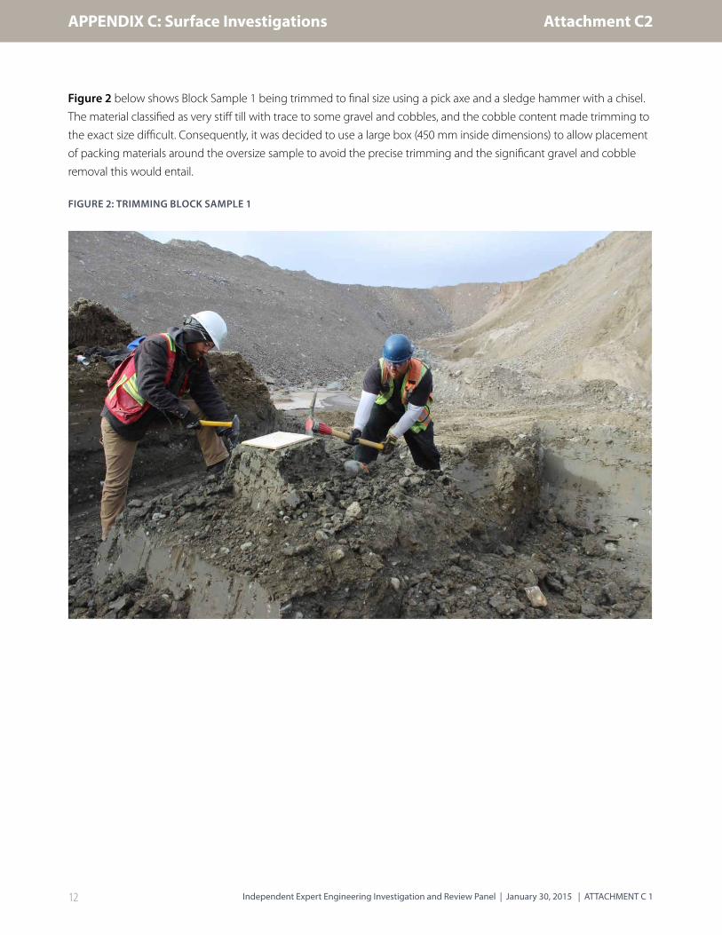
Figure 2 below shows Block Sample 1 being trimmed to final size using a pick axe and a sledge hammer with a chisel.
The material classified as very stiff till with trace to some gravel and cobbles, and the cobble content made trimming to
the exact size difficult. Consequently, it was decided to use a large box (450 mm inside dimensions) to allow placement
of packing materials around the oversize sample to avoid the precise trimming and the significant gravel and cobble
removal this would entail.
FIGURE 2: TRIMMING BLOCK SAMPLE 1
Attachment C2

Independent Expert Engineering Investigation and Review Panel | January 30, 2015 | ATTACHMENT C 113
APPENDIX C: Surface Investigations
Figure 3 below shows the final trimming step using 50 mm wide, 5 mm thick steel chisels with a single-beveled tip to
cut the sample from the base of the pedestal. Once the chisels had been inserted from all sides, the sample was pried
off the foundation using a flat shovel underneath the fully inserted chisels.
FIGURE 3: CHISELING THE BASE OF BLOCK SAMPLE 1
Attachment C2

Independent Expert Engineering Investigation and Review Panel | January 30, 2015 | ATTACHMENT C 114
APPENDIX C: Surface Investigations
Figure 4 below shows the pedestal prepared for Block Sample 2. The shear (A) passing through the pedestal is
denoted by a distinct contact between brown till fill on the upstream side and grey on the downstream side. It is not
known if the shear is also associated with a construction material interface.
FIGURE 4: PEDESTAL FOR BLOCK SAMPLE 2
Attachment C2
Independent Expert Engineering Investigation and Review Panel | January 30, 2015 | ATTACHMENT C 115
APPENDIX C: Surface Investigations
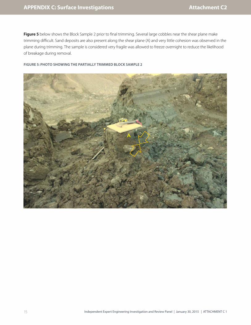
Figure 5 below shows the Block Sample 2 prior to final trimming. Several large cobbles near the shear plane make
trimming difficult. Sand deposits are also present along the shear plane (A) and very little cohesion was observed in the
plane during trimming. The sample is considered very fragile was allowed to freeze overnight to reduce the likelihood
of breakage during removal.
FIGURE 5: PHOTO SHOWING THE PARTIALLY TRIMMED BLOCK SAMPLE 2
Attachment C2

Independent Expert Engineering Investigation and Review Panel | January 30, 2015 | ATTACHMENT C 116
APPENDIX C: Surface Investigations
Figure 6 below shows Block Sample 2 being prepared for transport. The open plywood box was lowered over the
sample and packed with polystyrene foam on the sides. The top was then packed with polystyrene foam and the lid
screwed in place. The sample was tilted on its side for final trimming of the base and installation of the box bottom.
FIGURE 6: BASE OF BLOCK SAMPLE 2 READY FOR FINAL TRIMMING
Block sample 2 across the shear zone was subjected to scanning at FP Innovations at the University of British Columbia,
a facility capable of completing X-rays and CT scanning on large items. CT scanning on the block samples was
performed following several rounds of CT scans on thin-walled tube samples, which included a prototyping scanning
exercise to determine the scanning technique and orientation providing the best information.
The block sample remained in the field packaging and was oriented vertically when placed on the scanning platform.
CT scans were completed at horizontal slices at a 50 mm vertical spacing up the entire height of the sample. The CT
scanning method utilized does produce some noise in the images due to wave interference, typically manifesting as
small scale lineal features. A select CT scan is shown in Figure 7 where the shear zone can be clearly identified.
Attachment C2

Independent Expert Engineering Investigation and Review Panel | January 30, 2015 | ATTACHMENT C 117
APPENDIX C: Surface Investigations
FIGURE 7: ORIENTATION AND CONFIGURATION OF SHEAR ZONE IN BLOCK SAMPLE SCAN
Attachment C2
Related Documents