i PREFACE As an undergraduate from Electrical and Information engineering department of University of Ruhuna, I was assigned to 12 weeks industrial training program which was conducted by collaboration of National Apprentice and Industrial Training Authority (NAITA) and Engineering Education Centre of faculty of engineering. My industrial training establishment was ZTE Lanka (Pvt) Ltd which is one of the leading telecommunication corporation in Sri Lanka at Colombo 02. This report is a brief presentation of knowledge and experience I have obtained during my three month training period from 04 th of January to 25 th of March. This report consists of four main chapters. The first chapter of this report demonstrates a brief introduction to ZTE Lanka (Pvt) Ltd, Including history, vision and mission, present performance and organizational structure of ZTE Lanka (Pvt) Ltd. Second chapter describes the technical training experience that I got from ZTE Lanka (Pvt) Ltd. The chapter is further subdivided into Mobile Communication overview, BTS Installation, Drive Test, Transmission Technologies, Evaluation and Optimization. Technical and theoretical information are described under each sub headings. Third chapter gives the experience on management side, the administrative and office practices and safety procedures. Fourth chapter summarizes the training experience and it has conclusion of the training program from ZTE Lanka (Pvt) Ltd adopted by the EEC and NAITA. Anujan.K Department of Electrical and Information Engineering Faculty of Engineering University of Ruhuna

Welcome message from author
This document is posted to help you gain knowledge. Please leave a comment to let me know what you think about it! Share it to your friends and learn new things together.
Transcript
i
PREFACE
As an undergraduate from Electrical and Information engineering department of University
of Ruhuna, I was assigned to 12 weeks industrial training program which was conducted
by collaboration of National Apprentice and Industrial Training Authority (NAITA) and
Engineering Education Centre of faculty of engineering. My industrial training
establishment was ZTE Lanka (Pvt) Ltd which is one of the leading telecommunication
corporation in Sri Lanka at Colombo 02. This report is a brief presentation of knowledge
and experience I have obtained during my three month training period from 04th
of January
to 25th
of March.
This report consists of four main chapters. The first chapter of this report demonstrates a
brief introduction to ZTE Lanka (Pvt) Ltd, Including history, vision and mission, present
performance and organizational structure of ZTE Lanka (Pvt) Ltd.
Second chapter describes the technical training experience that I got from ZTE Lanka (Pvt)
Ltd. The chapter is further subdivided into Mobile Communication overview, BTS
Installation, Drive Test, Transmission Technologies, Evaluation and Optimization.
Technical and theoretical information are described under each sub headings.
Third chapter gives the experience on management side, the administrative and office
practices and safety procedures.
Fourth chapter summarizes the training experience and it has conclusion of the training
program from ZTE Lanka (Pvt) Ltd adopted by the EEC and NAITA.
Anujan.K
Department of Electrical and Information Engineering
Faculty of Engineering
University of Ruhuna
ii
ACKNOWLEDGEMENT
First of all I would like to pay my gratitude to those who helped, encouraged, and guided
me to successfully completing my first industrial training of 12 weeks at ZTE Lanka (Pvt)
Ltd. Also I must thank to Our Training Coordinator, Staff of Engineering Education Center
of Faculty of Engineering University of Ruhuna and Staff of NAITA for giving me an
opportunity to have a good training experience.
Specially I must thank to the Human Resource Manager of ZTE Lanka (Pvt) Ltd, Project
Manager of Mobitel Project, Staff from Mobitel project, My Training Coordinator,
Managers, Engineers, Technical officers in our project and those who spent their most
valuable time for me from other projects of ZTE Lanka (Pvt) Ltd.
Anujan.K
Department of Electrical and Information Engineering
Faculty of Engineering
University of Ruhuna
iii
Contents
PREFACE ............................................................................................................................... i
ACKNOWLEDGEMENT ..................................................................................................... ii
CHAPTER 01 ........................................................................................................................ 1
1. Introduction ............................................................................................................... 1
1.1 History of ZTE......................................................................................................... 1
1.2 Vision of ZTE .......................................................................................................... 2
1.3 Mission of ZTE ........................................................................................................ 2
1.4 Present Performance ................................................................................................ 2
1.5 Organizational Structure .......................................................................................... 3
CHAPTER 02 ........................................................................................................................ 4
2. Training Experiences-Technical ................................................................................ 4
2.1 Mobile Communication Overview .......................................................................... 5
2.1.1 First Generation Mobile Communication ......................................................... 5
2.1.2 Second Generation Mobile Communication .................................................... 6
2.1.3 Third Generation Mobile Communication ....................................................... 6
2.2 GSM Overview ........................................................................................................ 7
2.2.1 Introduction to GSM ......................................................................................... 7
2.2.2 Timeslot and Frame Structure .......................................................................... 8
2.2.3 Channel Structure ............................................................................................. 9
2.2.4 Type of GSM Standards ................................................................................. 10
2.2.5 Frequency reuse and cell planning ................................................................. 11
2.2.6 GSM System Architecture .............................................................................. 12
2.2.7 GSM Location Update .................................................................................... 15
2.2.8 Outgoing Call Process .................................................................................... 16
2.3 Base Trnsceiver Station (BTS) Installation ........................................................... 17
iv
2.3.1 BTS ................................................................................................................. 17
2.3.2 Hardware Structure of BTS ............................................................................ 18
2.3.3 Function Description of a BTS ....................................................................... 19
2.3.4 Hardware Installation Flow ............................................................................ 20
2.3.5 Working Process ............................................................................................. 21
2.3.6 My Experience in BTS installation ................................................................ 21
2.4 Transmission Technologies ................................................................................... 22
2.4.1 Microwave Links ............................................................................................ 22
2.4.2 PDH ................................................................................................................ 23
2.4.3 SDH ................................................................................................................ 23
Advantages of SDH ............................................................................................. 23
SDH Frame Structure .......................................................................................... 24
2.5 Drive Test .............................................................................................................. 26
2.5.1 Setting azimuth angle ..................................................................................... 26
2.5.2 Setting Tilting angle ....................................................................................... 27
2.5.3 Criteria on Drive Test ..................................................................................... 27
2.5.4 Devices ........................................................................................................... 28
2.5.5 Test Items ....................................................................................................... 28
2.5.6 Drive test Procedure ....................................................................................... 28
2.6 VSWR Test ............................................................................................................ 30
2.6.1 Measuring VSWR........................................................................................... 30
2.6.2 Return loss Measurement ............................................................................... 31
2.6.3 Distance-to-Fault Measurement ..................................................................... 31
2.6.4 My Experience on using Site Master .............................................................. 32
2.7 Reports on Telecommunication ............................................................................. 33
2.7.1 Technical Site Survey Report ......................................................................... 33
2.7.2 Single Site Verification Report....................................................................... 34
v
2.8 Key Performance Indicators .................................................................................. 36
2.8.1 LTE KPIs ........................................................................................................ 36
Accessibility KPIs ............................................................................................... 36
Retainability KPIs................................................................................................ 37
Mobility KPIs ...................................................................................................... 38
Traffic KPIs ......................................................................................................... 39
Availability KPIs ................................................................................................. 40
2.8.2 2GKPIs ........................................................................................................... 40
SDCCH Congestion Rate .................................................................................... 40
SDCCH Call Drop Rate ....................................................................................... 40
TCH Assignment Success Rate ........................................................................... 41
TCH Call Drop Rate ............................................................................................ 42
Handover Success Rate ....................................................................................... 42
Success Rate of Call Setup .................................................................................. 42
Call Complete Success Rate ................................................................................ 43
Drop Call ............................................................................................................. 43
CHAPTER 03 ...................................................................................................................... 44
3. Training Experience – Management ........................................................................ 44
3.1 Transport Management .......................................................................................... 44
3.2 Office Practices ...................................................................................................... 45
CHAPTER 04 ...................................................................................................................... 46
4. Summary and Conclusion ........................................................................................ 46
4.1 Summary ................................................................................................................ 46
4.2 Conclusion ............................................................................................................. 46
References ........................................................................................................................... 48
List of Corrections ............................................................................................................... 49
vi
Figures
Figure 1.1-Global Logo of ZTE ---------------------------------------------------------------------- 1
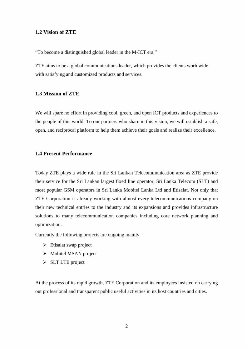
Figure 1.2- Organizational Structure ---------------------------------------------------------------- 3
Figure 2.1-Frequency sharing by Operators -------------------------------------------------------- 8
Figure 2.2-GSM Frame Structure -------------------------------------------------------------------- 9
Figure 2.3-GSM Channel Structure ---------------------------------------------------------------- 10
Figure 2.4-Cell Planning ----------------------------------------------------------------------------- 11
Figure 2.5-Frequency reuse pattern for N=4 & N=7 --------------------------------------------- 12
Figure 2.6-a BTS Site -------------------------------------------------------------------------------- 17
Figure 2.7-BTS Shelf --------------------------------------------------------------------------------- 18
Figure 2.8-BTS shelf in Gale Oya site ------------------------------------------------------------- 19
Figure 2.9-BTS Function Flow---------------------------------------------------------------------- 19
Figure 2.10-BTS Hardware installation flow ----------------------------------------------------- 20
Figure 2.11-Connections in BTS-------------------------------------------------------------------- 21
Figure 2.12-MW Equipment ------------------------------------------------------------------------ 22
Figure 2.13-SDH Frame Structure ------------------------------------------------------------------ 24
Figure 2.14-Setting azimuth angle ------------------------------------------------------------------ 26
Figure 2.15-Setting tilting angle -------------------------------------------------------------------- 27
Figure 2.16-Voice long call RSCP plot of a drive test ------------------------------------------- 29
Figure 2.17-Call drop plot of a drive test ---------------------------------------------------------- 29
Figure 2.18-Site Master ------------------------------------------------------------------------------ 30
Figure 2.19-Ruturn loss ------------------------------------------------------------------------------ 31
Figure 2.20-DTF measurement --------------------------------------------------------------------- 32
Figure 2.21-Some details in TSSR ----------------------------------------------------------------- 33
Figure 2.22-Location plots in TSSR---------------------------------------------------------------- 34
Figure 2.23-Site details in SSV --------------------------------------------------------------------- 35
Figure 2.24-Plots in SSV ----------------------------------------------------------------------------- 35
Figure 2.25-RRC Establishment -------------------------------------------------------------------- 36
vii
Tables
Table 2.1-Training Schedule ................................................................................................. 4
Table 2.2-Different between 1st and 2nd Generations .......................................................... 7
Table 2.3-Frequncy Resource .............................................................................................. 11
Table 2.4-GSM System Architecture .................................................................................. 12
Table 2.5-Function Description of BTS .............................................................................. 20
Table 2.6-Test items of Drive test ....................................................................................... 28
1
CHAPTER 01
1. Introduction
1.1 History of ZTE
ZTE (Zhong Xing Telecommunication Equipment Company Limited) Corporation is a
global leader in telecommunications and information technology. As part of ZTE’s M-ICT
strategy, the company is committed to provide integrated end-to-end innovations to deliver
excellence and value to consumers, carriers, businesses and public sector customers around
the world, enabling increased connectivity and productivity to unlock the power of
technology for society. Founded in 1985, ZTE is listed on both the Hong Kong and
Shenzhen Stock Exchanges and is China’s largest-listed telecommunications equipment
company.
As one of the first Chinese telecoms equipment provider to pursue business in overseas
markets, ZTE now has about 62,000 employees and 8,000 of them are working in about
140 representative offices around the world including Sri Lanka.
ZTE Corporation established their branch at Sri Lanka in 2003 which was located at 3rd
floor, IBM building, Nawam Mawatha, Colombo02. ZTE is already working with almost
every telecom company on their new technical entries to the industry and its expansions.
ZTE Lanka branch has established other regional offices at Kandy, Dambulla and also
Kurunagala. Now ZTE Corporation handles all of leading operator's networks in Sri Lanka
in mobile and fixed lines including Sri Lanka Telecom, Etisalat and also Mobitel Lanka
Ltd.
Figure 1.1-Global Logo of ZTE
2
1.2 Vision of ZTE
“To become a distinguished global leader in the M-ICT era.”
ZTE aims to be a global communications leader, which provides the clients worldwide
with satisfying and customized products and services.
1.3 Mission of ZTE
We will spare no effort in providing cool, green, and open ICT products and experiences to
the people of this world. To our partners who share in this vision, we will establish a safe,
open, and reciprocal platform to help them achieve their goals and realize their excellence.
1.4 Present Performance
Today ZTE plays a wide rule in the Sri Lankan Telecommunication area as ZTE provide
their service for the Sri Lankan largest fixed line operator, Sri Lanka Telecom (SLT) and
most popular GSM operators in Sri Lanka Mobitel Lanka Ltd and Etisalat. Not only that
ZTE Corporation is already working with almost every telecommunications company on
their new technical entries to the industry and its expansions and provides infrastructure
solutions to many telecommunication companies including core network planning and
optimization.
Currently the following projects are ongoing mainly
Etisalat swap project
Mobitel MSAN project
SLT LTE project
At the process of its rapid growth, ZTE Corporation and its employees insisted on carrying
out professional and transparent public useful activities in its host countries and cities.
3
1.5 Organizational Structure
Figure 1.2- Organizational Structure
4
CHAPTER 02
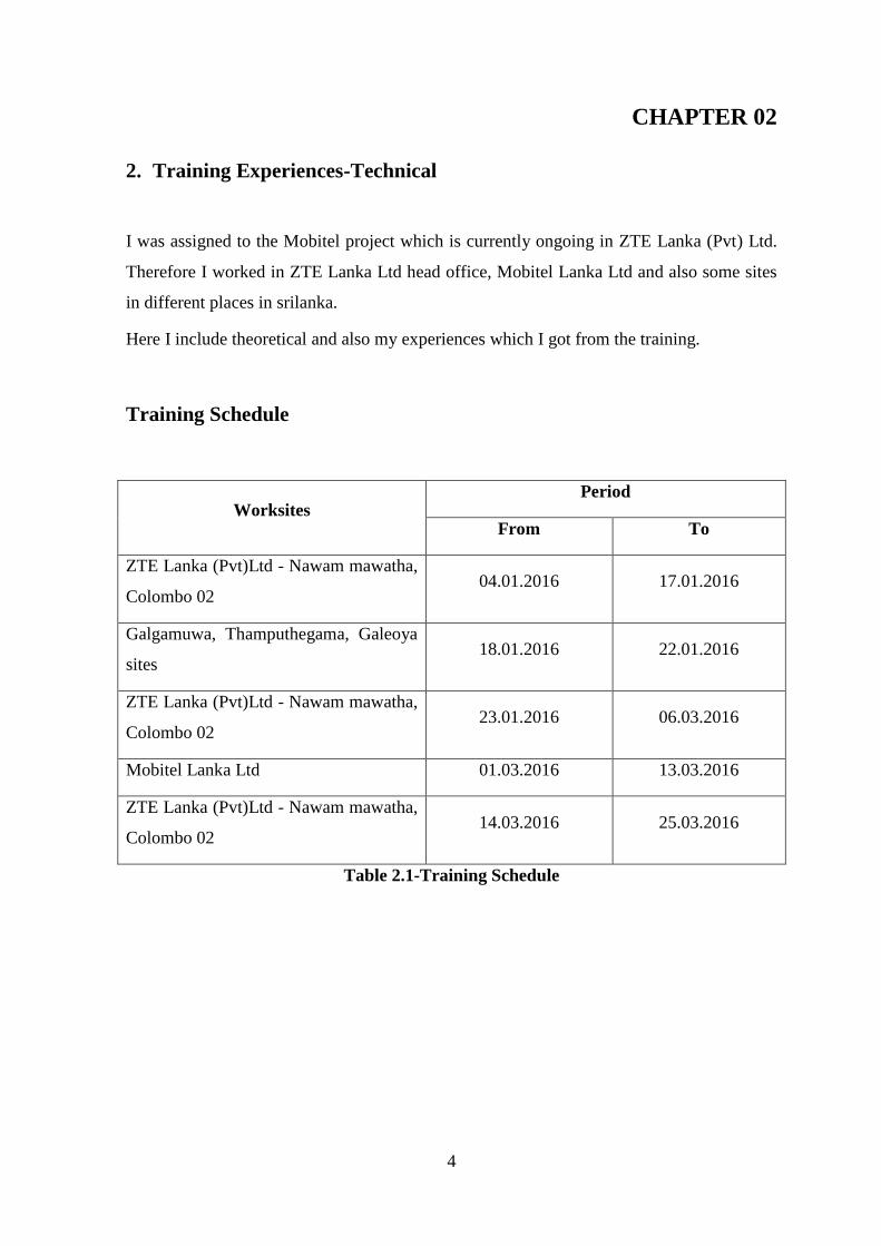
2. Training Experiences-Technical
I was assigned to the Mobitel project which is currently ongoing in ZTE Lanka (Pvt) Ltd.
Therefore I worked in ZTE Lanka Ltd head office, Mobitel Lanka Ltd and also some sites
in different places in srilanka.
Here I include theoretical and also my experiences which I got from the training.
Training Schedule
Worksites Period
From To
ZTE Lanka (Pvt)Ltd - Nawam mawatha,
Colombo 02 04.01.2016 17.01.2016
Galgamuwa, Thamputhegama, Galeoya
sites 18.01.2016 22.01.2016
ZTE Lanka (Pvt)Ltd - Nawam mawatha,
Colombo 02 23.01.2016 06.03.2016
Mobitel Lanka Ltd 01.03.2016 13.03.2016
ZTE Lanka (Pvt)Ltd - Nawam mawatha,
Colombo 02 14.03.2016 25.03.2016
Table 2.1-Training Schedule
5
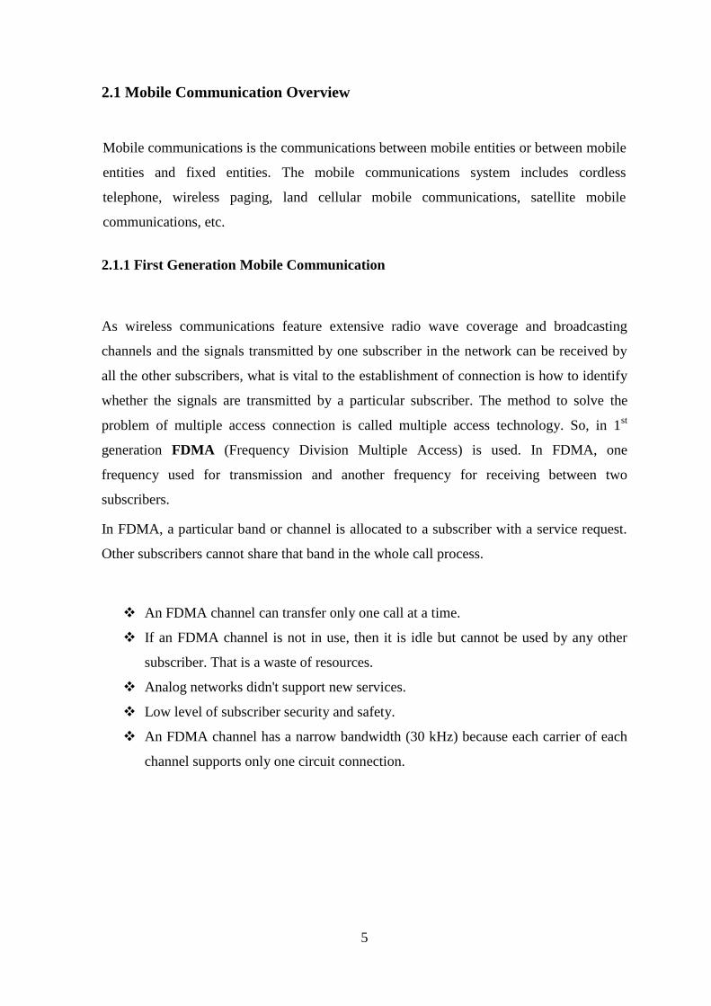
2.1 Mobile Communication Overview
Mobile communications is the communications between mobile entities or between mobile
entities and fixed entities. The mobile communications system includes cordless
telephone, wireless paging, land cellular mobile communications, satellite mobile
communications, etc.
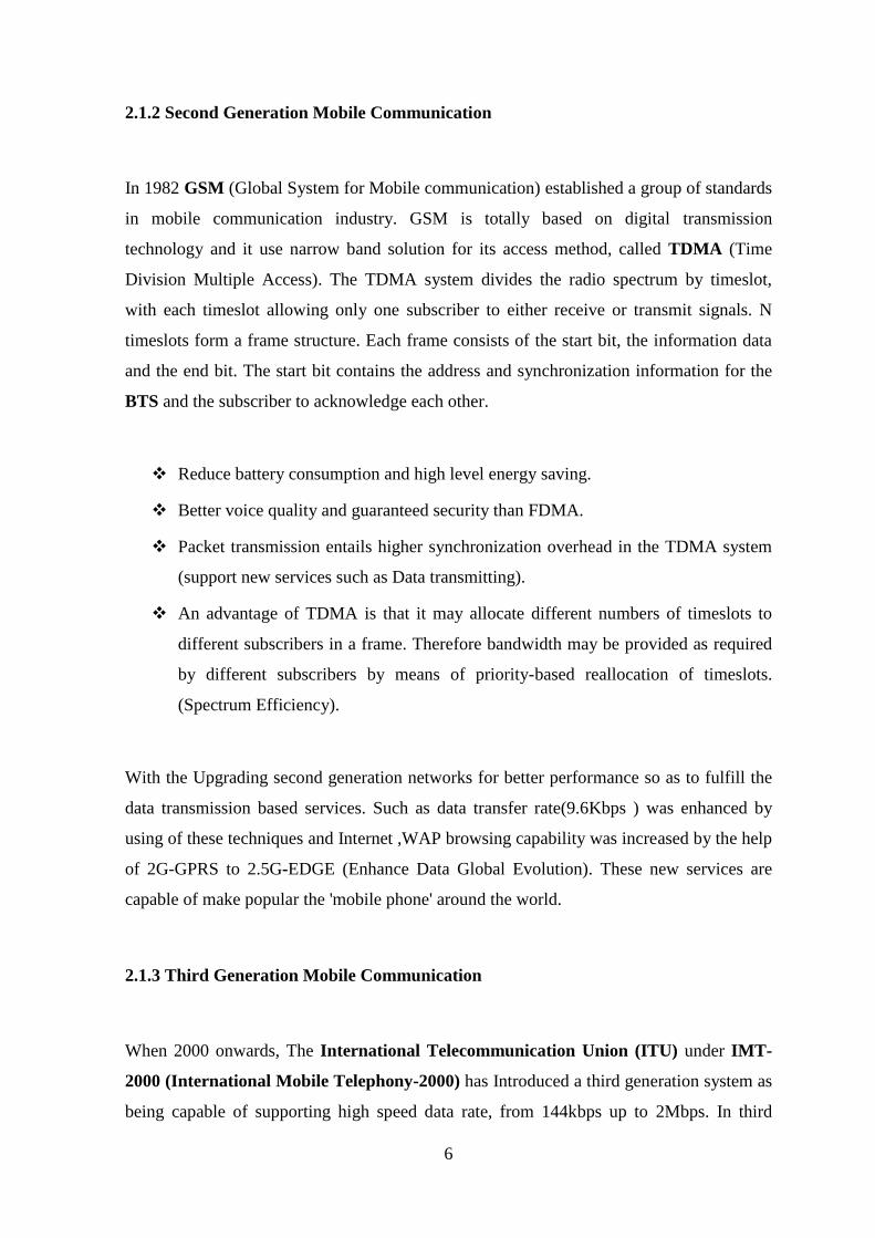
2.1.1 First Generation Mobile Communication
As wireless communications feature extensive radio wave coverage and broadcasting
channels and the signals transmitted by one subscriber in the network can be received by
all the other subscribers, what is vital to the establishment of connection is how to identify
whether the signals are transmitted by a particular subscriber. The method to solve the
problem of multiple access connection is called multiple access technology. So, in 1st
generation FDMA (Frequency Division Multiple Access) is used. In FDMA, one
frequency used for transmission and another frequency for receiving between two
subscribers.
In FDMA, a particular band or channel is allocated to a subscriber with a service request.
Other subscribers cannot share that band in the whole call process.
An FDMA channel can transfer only one call at a time.
If an FDMA channel is not in use, then it is idle but cannot be used by any other
subscriber. That is a waste of resources.
Analog networks didn't support new services.
Low level of subscriber security and safety.
An FDMA channel has a narrow bandwidth (30 kHz) because each carrier of each
channel supports only one circuit connection.
6
2.1.2 Second Generation Mobile Communication
In 1982 GSM (Global System for Mobile communication) established a group of standards
in mobile communication industry. GSM is totally based on digital transmission
technology and it use narrow band solution for its access method, called TDMA (Time
Division Multiple Access). The TDMA system divides the radio spectrum by timeslot,
with each timeslot allowing only one subscriber to either receive or transmit signals. N
timeslots form a frame structure. Each frame consists of the start bit, the information data
and the end bit. The start bit contains the address and synchronization information for the
BTS and the subscriber to acknowledge each other.
Reduce battery consumption and high level energy saving.
Better voice quality and guaranteed security than FDMA.
Packet transmission entails higher synchronization overhead in the TDMA system
(support new services such as Data transmitting).
An advantage of TDMA is that it may allocate different numbers of timeslots to
different subscribers in a frame. Therefore bandwidth may be provided as required
by different subscribers by means of priority-based reallocation of timeslots.
(Spectrum Efficiency).
With the Upgrading second generation networks for better performance so as to fulfill the
data transmission based services. Such as data transfer rate(9.6Kbps ) was enhanced by
using of these techniques and Internet ,WAP browsing capability was increased by the help
of 2G-GPRS to 2.5G-EDGE (Enhance Data Global Evolution). These new services are
capable of make popular the 'mobile phone' around the world.
2.1.3 Third Generation Mobile Communication
When 2000 onwards, The International Telecommunication Union (ITU) under IMT-
2000 (International Mobile Telephony-2000) has Introduced a third generation system as
being capable of supporting high speed data rate, from 144kbps up to 2Mbps. In third
7
generation mobile networks wide frequency band was used with CDMA (Code Division
Multiple Access method).
In the CDMA system, all subscribers use the same frequency and can transmit signals at
the same time. Every subscriber has its own pseudo-random code, which is almost
orthogonal to the codes of other subscribers. The receiver performs a time-dependent
operation to detect the unique code needed. All other irrelevant codes are regarded as
noise. To detect signals, the receiver needs to know the code used by the transmitter.
Many subscribers in the CDMA system share the same frequency.
Unlike TDMA and FDMA, CDMA does not strictly limit the number of
subscribers. Of course the performance of the system will deteriorate with the
increase of subscribers and, correspondingly, will improve with the decrease of
subscribers.
Self-interference is a problem of the CDMA system. Self-interference results from
incomplete orthogonality of the spread spectrum sequences of different subscribers.
2.2 GSM Overview
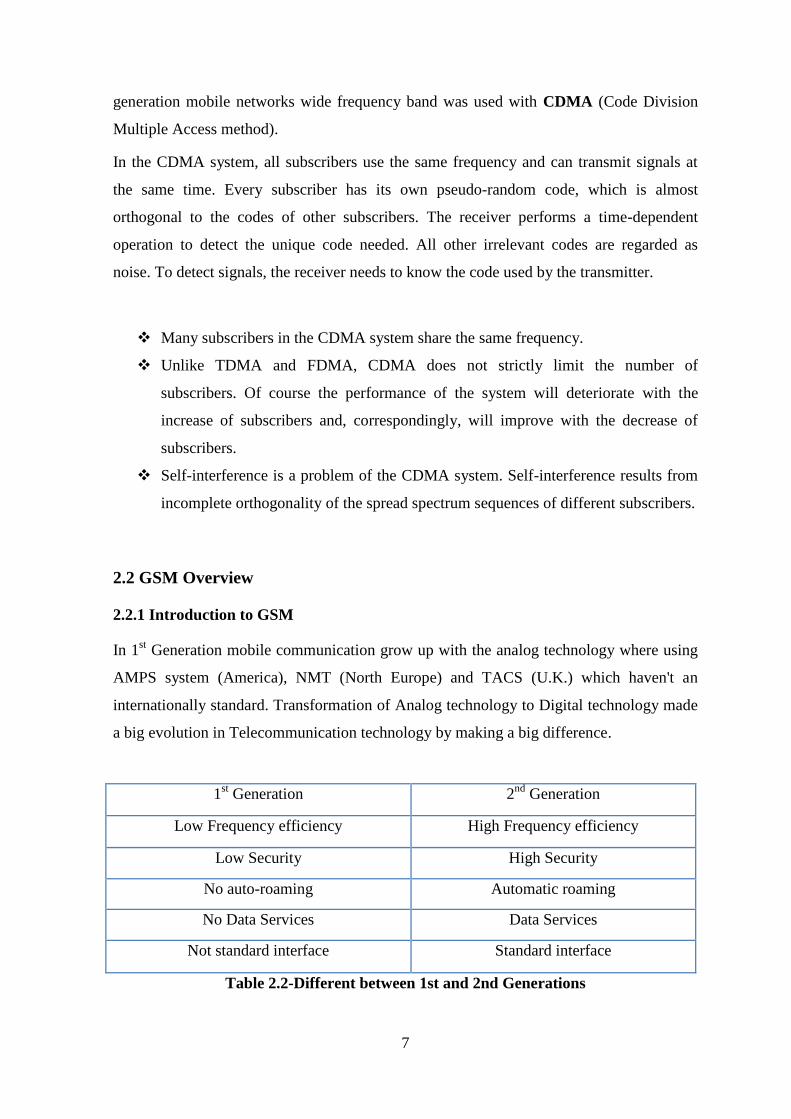
2.2.1 Introduction to GSM
In 1st Generation mobile communication grow up with the analog technology where using
AMPS system (America), NMT (North Europe) and TACS (U.K.) which haven't an
internationally standard. Transformation of Analog technology to Digital technology made
a big evolution in Telecommunication technology by making a big difference.
1st Generation 2
nd Generation
Low Frequency efficiency High Frequency efficiency
Low Security High Security
No auto-roaming Automatic roaming
No Data Services Data Services
Not standard interface Standard interface
Table 2.2-Different between 1st and 2nd Generations
8
Also technique that use for the mobile communication has changed with the evolution of
analog to digital conversion.
2.2.2 Timeslot and Frame Structure
First, the user voice is digitalizing using a RPE-LPC code (Regular Pulse Excited-Linear
Productive Code). Then this binary code id time allocating for each user in the call
duration time. In range of radio frequency range, there are two frequency range groups
used for the down-link & up-link.
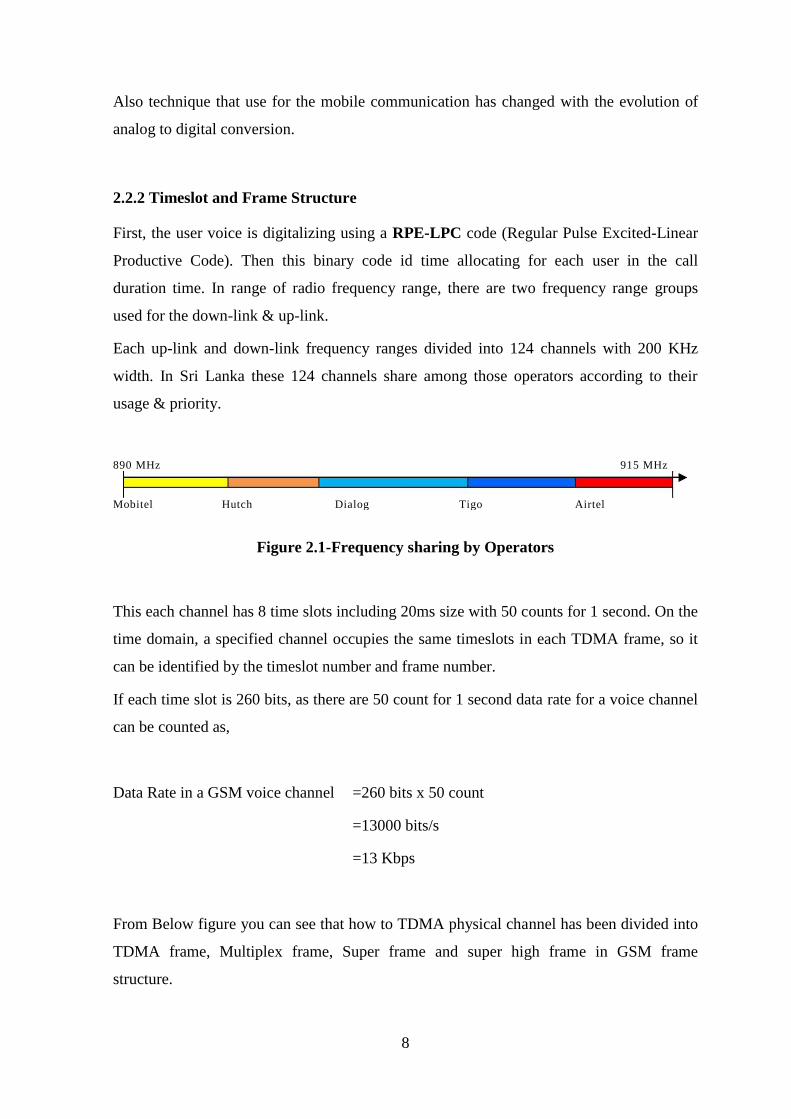
Each up-link and down-link frequency ranges divided into 124 channels with 200 KHz
width. In Sri Lanka these 124 channels share among those operators according to their
usage & priority.
Figure 2.1-Frequency sharing by Operators
This each channel has 8 time slots including 20ms size with 50 counts for 1 second. On the
time domain, a specified channel occupies the same timeslots in each TDMA frame, so it
can be identified by the timeslot number and frame number.
If each time slot is 260 bits, as there are 50 count for 1 second data rate for a voice channel
can be counted as,
Data Rate in a GSM voice channel =260 bits x 50 count
=13000 bits/s
=13 Kbps
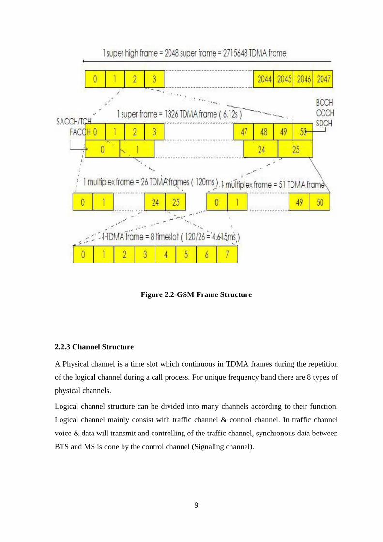
From Below figure you can see that how to TDMA physical channel has been divided into
TDMA frame, Multiplex frame, Super frame and super high frame in GSM frame
structure.
890 MHz 915 MHz
Mobitel Hutch Dialog Tigo Airtel
9
Figure 2.2-GSM Frame Structure
2.2.3 Channel Structure
A Physical channel is a time slot which continuous in TDMA frames during the repetition
of the logical channel during a call process. For unique frequency band there are 8 types of
physical channels.
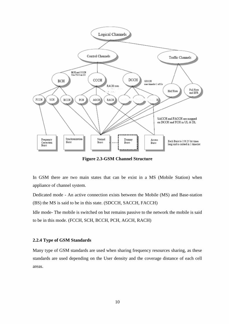
Logical channel structure can be divided into many channels according to their function.
Logical channel mainly consist with traffic channel & control channel. In traffic channel
voice & data will transmit and controlling of the traffic channel, synchronous data between
BTS and MS is done by the control channel (Signaling channel).
10
Figure 2.3-GSM Channel Structure
In GSM there are two main states that can be exist in a MS (Mobile Station) when
appliance of channel system.
Dedicated mode - An active connection exists between the Mobile (MS) and Base-station
(BS) the MS is said to be in this state. (SDCCH, SACCH, FACCH)
Idle mode- The mobile is switched on but remains passive to the network the mobile is said
to be in this mode. (FCCH, SCH, BCCH, PCH, AGCH, RACH)
2.2.4 Type of GSM Standards
Many type of GSM standards are used when sharing frequency resources sharing, as these
standards are used depending on the User density and the coverage distance of each cell
areas.
11
GSM900 GSM1800 EGSM900 GSM1900
Up 890-915 MHz 1710-1785 MHz 880-915 MHz 1850-1910 MHz
Down 935-960 MHz 1805-1880 MHz 925-960 MHz 1930-1990 MHz
Duplex interval 45 MHz 95 MHz 45 MHz 80 MHz
Band width 25 MHz 75 MHz 35 MHz 60 MHz
Frequency interval 200 KHz 200 KHz 200 KHz 200 KHz
Table 2.3-Frequncy Resource
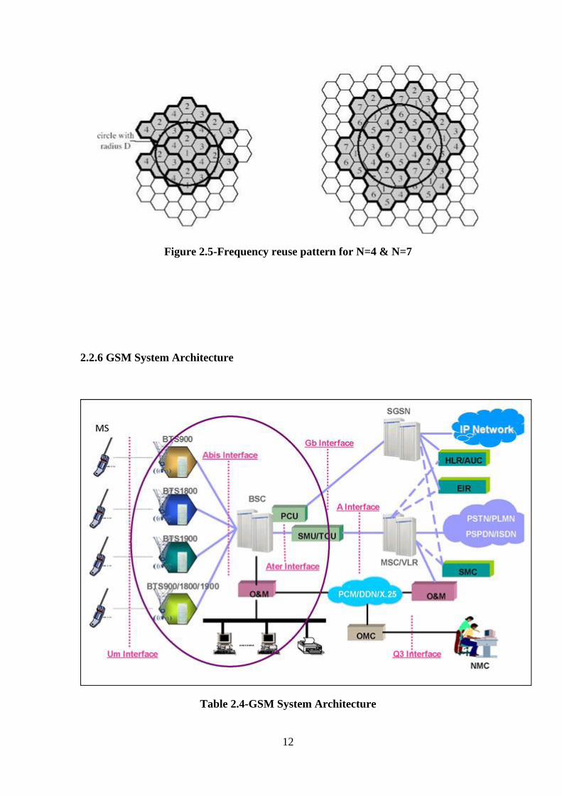
2.2.5 Frequency reuse and cell planning
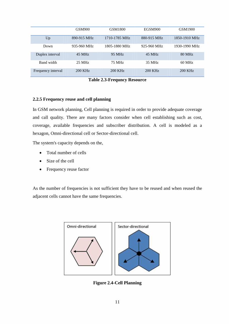
In GSM network planning, Cell planning is required in order to provide adequate coverage
and call quality. There are many factors consider when cell establishing such as cost,
coverage, available frequencies and subscriber distribution. A cell is modeled as a
hexagon, Omni-directional cell or Sector-directional cell.
The system's capacity depends on the,
Total number of cells
Size of the cell
Frequency reuse factor
As the number of frequencies is not sufficient they have to be reused and when reused the
adjacent cells cannot have the same frequencies.
Figure 2.4-Cell Planning
12
Figure 2.5-Frequency reuse pattern for N=4 & N=7
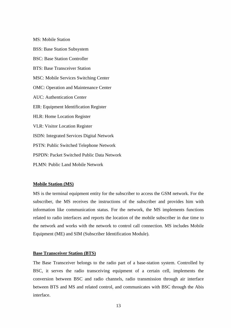
2.2.6 GSM System Architecture
Table 2.4-GSM System Architecture
13
MS: Mobile Station
BSS: Base Station Subsystem
BSC: Base Station Controller
BTS: Base Transceiver Station
MSC: Mobile Services Switching Center
OMC: Operation and Maintenance Center
AUC: Authentication Center
EIR: Equipment Identification Register
HLR: Home Location Register
VLR: Visitor Location Register
ISDN: Integrated Services Digital Network
PSTN: Public Switched Telephone Network
PSPDN: Packet Switched Public Data Network
PLMN: Public Land Mobile Network
Mobile Station (MS)
MS is the terminal equipment entity for the subscriber to access the GSM network. For the
subscriber, the MS receives the instructions of the subscriber and provides him with
information like communication status. For the network, the MS implements functions
related to radio interfaces and reports the location of the mobile subscriber in due time to
the network and works with the network to control call connection. MS includes Mobile
Equipment (ME) and SIM (Subscriber Identification Module).
Base Transceiver Station (BTS)
The Base Transceiver belongs to the radio part of a base-station system. Controlled by
BSC, it serves the radio transceiving equipment of a certain cell, implements the
conversion between BSC and radio channels, radio transmission through air interface
between BTS and MS and related control, and communicates with BSC through the Abis
interface.
14
Base Station Controller (BSC)
One end of the BSC can be connected with one or more BTSs, while its other end can be
connected with MSC and OMC.BTS implements radio network management and BTS
monitoring and it also controls the establishment, connection and disconnection of radio
connection between MS and BTS. Not only that BSC control the positioning, handoff and
paging of MS, voice coding and rate adjustment and carries out operation and maintenance
of the BSS.
Mobile Switching Center (MSC)
MSC is the core of the GSM/CDMA network. It controls and implements voice channel
connection for MSs within its coverage, namely serving as an interface between GSM and
other networks. The functions MSC carries out the include call connection, charging, BSS-
MSC handoff and assist radio resource management. Besides, MSC also implements the
call route establishment to the MS, namely to query the location information of each MS.
Visitor Location Register (VLR)
The VLR is a dynamic user database, storing the related user data of all MSs (visitors)
within the MSC's management range, including user ID, MS's location are information,
user status and services available for the user. VLR gets and stores all necessary data from
the HLR of a mobile subscriber. Once the mobile subscriber leaves the control area of the
VLR, it will be registered in another VLR, and the previous VLR will delete its data log.
The interface between MSC and VLR is B interface.
Home Location Register (HLR)
The HLR is a static database, storing the data for mobile subscriber management. Each
mobile subscriber should be registered in its HLR. It stores two kinds of information:
parameters related with the mobile subscriber, including the subscriber's ID, access
capability, user type and current location information of the subscriber for call route
establishment.
15
Authentication Center (AUC)
The AUC, a functional entity managing the authentication information related with mobile
stations(MS).It implements the MS authentication, stores the MS authentication
parameters, generate and sends the corresponding authentication parameters according to
the request of MSC or VLR and then calculates all random numbers to get the
authentication result.
Short Message Center (SC)
The SC is responsible for receiving, storing and forwarding short messages between the
mobile to mobile. It serves as a postal office, receiving mils from every place, sorts them
out then distribute them to the corresponding users. Through SC, the messages can be sent
to destination more reliably using point-to-point server and cell broadcast service. The
interface between SC and HLR is M interface.
Operation and Maintenance Management Subsystem (OMC)
The OMC provides equipment operators with network operation and maintenance services,
makes network planning and improve the efficiency and service quality of the whole
system. OMC includes OMC-S and OMC-R, depending on the part for maintenance.
OMC-S is responsible for the maintenance on the MSS side while OMC-R is responsible
for the maintenance on the BSS side. Its specific functions include: maintenance test,
obstacle check and handling, real-time system control, subscriber tracking, alarm and
traffic measurement. . The interface between BSC, MSC and OMM is M interface.
2.2.7 GSM Location Update
A GSM network is divided into cells. A group of cells is considered a location area. A
mobile phone in motion keeps the network informed about changes in the location area. If
the mobile moves from a cell in one location area to a cell in another location area, the
mobile phone should perform a location area update to inform the network about the exact
location of the mobile phone. Location area update only happen in Idle state (Phone is not
16
busy) of the phone. Always LU happens by requesting IMSI information from phone and
requesting user data HLR to VLR.
2.2.8 Outgoing Call Process
MS sends a channel request message to the BSC, requesting BSC to assign the
dedicated control channel to the MS, and BSC assigns a channel to the MS.
The MS sends the service request message CM-SER-REQ to the MSC/VLR. The
MSC/VLR sets up a SCCP connection first and then sends connection confirmation
message to the MS.
MSC/VLR authenticates the user and verifies its legality.
If ciphering is required, the MSC/VLR requests the BSC to encipher the air
channels for the user. The BSC sends a ciphering command to the mobile phone.
And after the mobile phone starts the ciphering mode, it sends the ciphering
completion message to BSC and then BSC sends an acknowledgement to
MSC/VLR.
After the MS receives the service request accept message, it sends MSC/VLR the
SETUP message. If it is allowed by the call, MSC/VLR sends the "Call Proceeding
message" to MS through BSC, indicating that the call request has been accepted.
Terrestrial circuit assignment for the mobile phone of the calling party.
The called party rings, informing the calling party. The called party responds,
sending a response message to the calling party, thus entering the conversation
status.
17
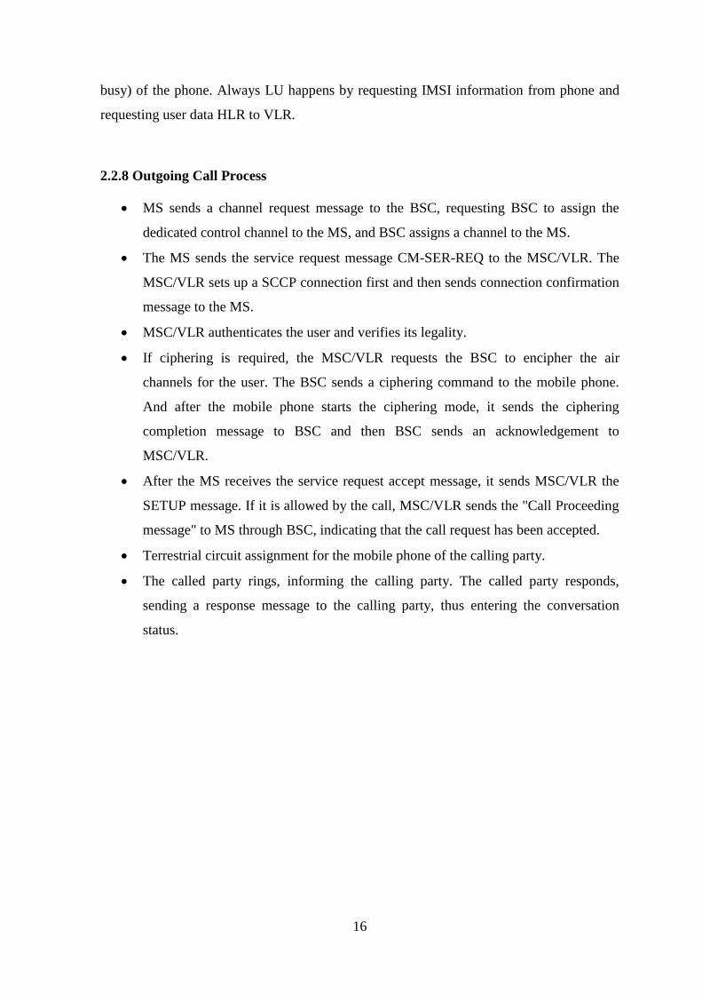
2.3 Base Trnsceiver Station (BTS) Installation
2.3.1 BTS
A base transceiver station or cell site (BTS) is a piece of equipment that facilitates wireless
communication between user equipment (UE) and a network BTS is also referred to as the
radio base station (RBS), node B (in 3G Networks) or, simply, the base station (BS). BTS
is controlled by a parent base station controller (BSC).
Figure 2.6-a BTS Site
1. Lightning arrester
2. Antenna jumper
3. Tower top amplifier
4. Pole
18
5. Antenna
6. Feeder cable
7. Feeder clip
8. Iron tower
9. Copper grounding bar
10. Feeder window
11. Cabling rack
12. Cabinet-top jumper
13. BTS equipment
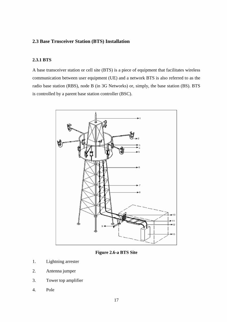
2.3.2 Hardware Structure of BTS
There are versions of BTS equipments are made by many manufactures/Vendors. Today,
from those products ZXG10-BTS family have gotten a good place in radio network system
in ZTE products. The ZXG10-BTS (V1.0) is an indoor macro-cell BTS with large
capacity, great integration and high reliability.
Figure 2.7-BTS Shelf
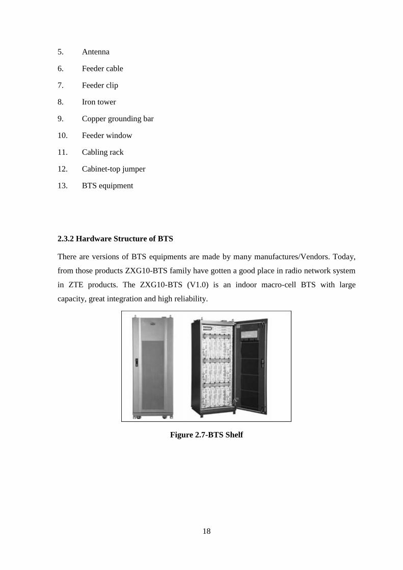
19
Figure 2.8-BTS shelf in Gale Oya site
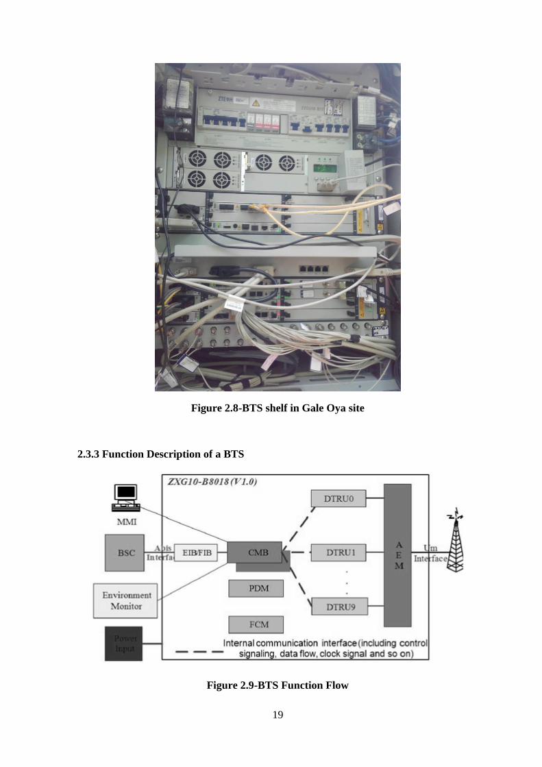
2.3.3 Function Description of a BTS
Figure 2.9-BTS Function Flow
20
Module Description
EIB/FIB EIB supports E1/T1 interfaces. FIB supports 100BASE-T interface.
CMB CMB provides basic operation including Alarm control,
Synchronization and radio resource control.
DTRU Providing all the radio functions related with terminal
communications.
AEM AEM is in charge of combining several TX signals towards antenna,
including CDU, ECDU, CEUT.
PDM PDM provides the power distribution function.
Table 2.5-Function Description of BTS
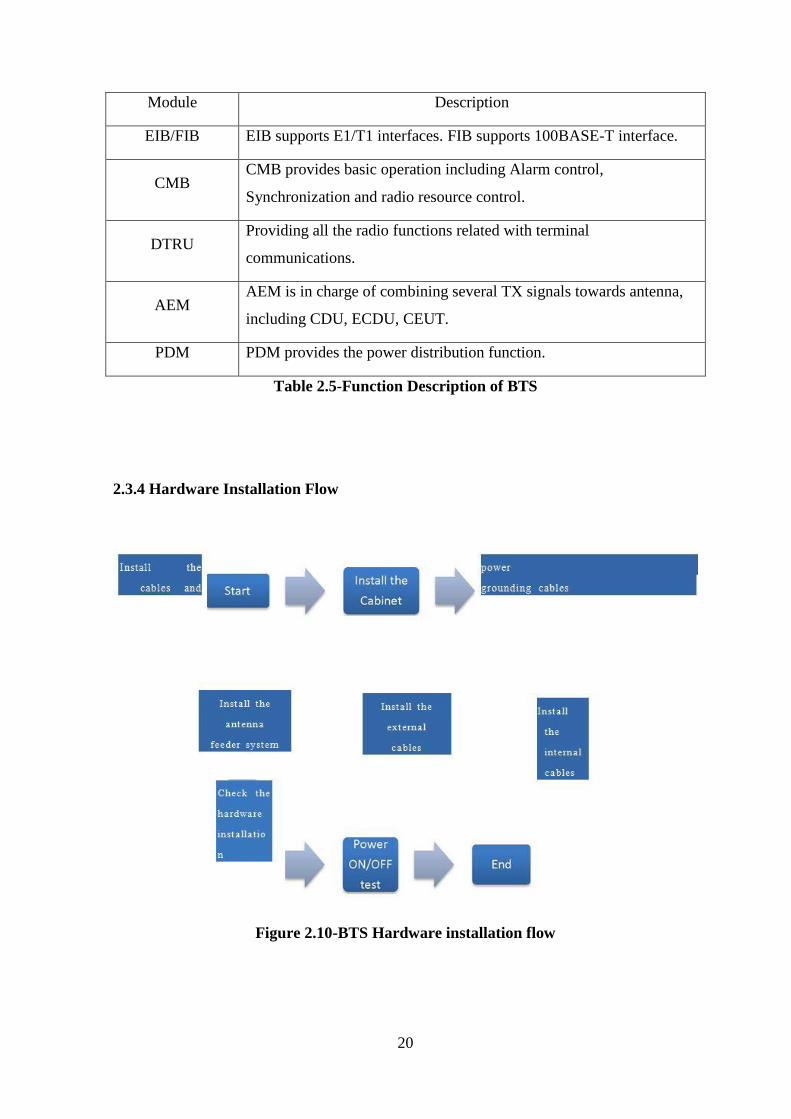
2.3.4 Hardware Installation Flow
Figure 2.10-BTS Hardware installation flow
21
2.3.5 Working Process
ZXG10 M8206 (V1.00) provides perfect signal flow in uplink and downlink direction. On
the antenna side the duplexers are used to duplex the uplink and down link signal.
Duplexers take uplink signals from power amplifiers and provide down link signals to low
noise amplifiers. On the other side MEIB (Micro Base Station E1 Interface Board) board
provide Abis interface with the BSC. MEIB gives the downlink signals and takes uplink
signals to the CMB. CMB controls and switches uplink and down link signal to other parts
of BTS.
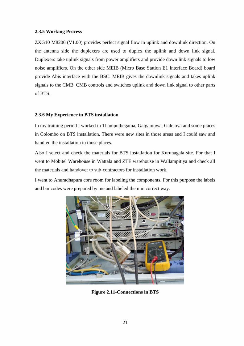
2.3.6 My Experience in BTS installation
In my training period I worked in Thamputhegama, Galgamuwa, Gale oya and some places
in Colombo on BTS installation. There were new sites in those areas and I could saw and
handled the installation in those places.
Also I select and check the materials for BTS installation for Kurunagala site. For that I
went to Mobitel Warehouse in Wattala and ZTE warehouse in Wallampitiya and check all
the materials and handover to sub-contractors for installation work.
I went to Anuradhapura core room for labeling the components. For this purpose the labels
and bar codes were prepared by me and labeled them in correct way.
Figure 2.11-Connections in BTS
22
2.4 Transmission Technologies
In data transmission there are many transmission types can be used. The data transfer rates
are varying according to the technique that has been used. In the telecommunication area
there are many methods to transfer data BTS-to-BTS or BTS-to-BSC.
Radio Link (Microwave)
Coaxial cable link
Satellite air way
Fiber-optic cable
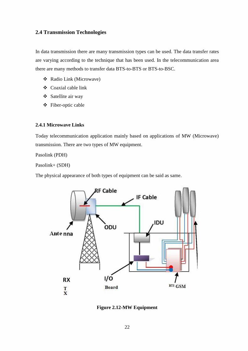
2.4.1 Microwave Links
Today telecommunication application mainly based on applications of MW (Microwave)
transmission. There are two types of MW equipment.
Pasolink (PDH)
Pasolink+ (SDH)
The physical appearance of both types of equipment can be said as same.
Figure 2.12-MW Equipment
23
2.4.2 PDH
The Plesiochronous Digital Hierarchy (PDH) is a technology used in telecommunications
networks to transport large quantities of data over digital signal transmit path. A PDH fiber
link consists of two fibers, one for data in each direction, and a terminal station at each end
to drive light into one fiber, and detect it from the other, whilst sending and receiving data
to nearby equipment with electrical signals. If the link (E1 or T1) is more than about 50 km
long, then regenerator stations must be installed, to detect the light from the fiber on the
first leg of the link, recover the data bits and use this to modulate a laser to drive the
second leg. PDH systems are point-to-point, bi- directional digital data links at rates of up
to 2 Mbps.
2.4.3 SDH
Synchronous Digital Hierarchy defines the frame structure, multiplexing method, and
transmission rate and interface code pattern. Wherever SDH only use in main ring.
Advantages of SDH
Interface
Electrical interface-SDH provides a set of standard rate levels, STM-N (N=4n=1, 4,
16, 64....)
Optical interface-Optical interface adopt universal standards.
Multiplexing method
Low-rate SDH signals High-rate SDH (Byte interleaved multiplexing method).
Synchronous multiplexing method and flexible mapping structure.
Operation and Maintenance
Abundant overhead bits are used for OAM.
Unnecessary to add redundancy bits to monitor line performance during line
coding.
24
Compatibility
SDH network and the existing PDH network can work together.
SDH network can accommodate the signals of other hierarchies such as ATM,
FDDI and Ethernet.
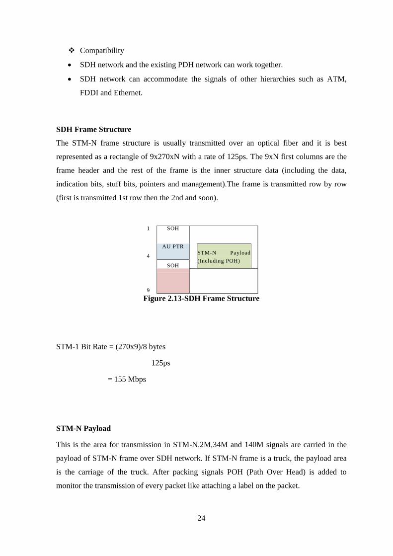
SDH Frame Structure
The STM-N frame structure is usually transmitted over an optical fiber and it is best
represented as a rectangle of 9x270xN with a rate of 125ps. The 9xN first columns are the
frame header and the rest of the frame is the inner structure data (including the data,
indication bits, stuff bits, pointers and management).The frame is transmitted row by row
(first is transmitted 1st row then the 2nd and soon).
1 SOH
4
AU PTR
STM-N Payload
(Including POH)
SOH
9
Figure 2.13-SDH Frame Structure
STM-1 Bit Rate = (270x9)/8 bytes
125ps
= 155 Mbps
STM-N Payload
This is the area for transmission in STM-N.2M,34M and 140M signals are carried in the
payload of STM-N frame over SDH network. If STM-N frame is a truck, the payload area
is the carriage of the truck. After packing signals POH (Path Over Head) is added to
monitor the transmission of every packet like attaching a label on the packet.
25
SOH
Monitors the whole STM-N frame, monitor performance of all packages in the carriage of
the truck .There are 2 types of SOH structures. RSOH (Regenerator Section Overhead) is
to monitor the whole STM-N frame and MSOH (Multiplex Section Overhead) is to
monitors each STM-1 of the STM-N frame.
AU-PTR
This is used for alignment of lower rate signals in the payload of STM-N frame to
accurately locate the payload.AU-PTR is added in transmission end, when the signal is
packed in to the payload of STM-N frame like setting a coordinate value to identify the
package. At receiving end, the low rate signals are dropped from STM-N frame according
to the AU-PTR coordinate value.
26
2.5 Drive Test
Drive testing is the most common and maybe the best way to analyze Network
performance by means of coverage evaluation, system availability, network capacity,
network retainibility and call quality. Although it gives idea only on downlink side of the
process, it provides huge perspective to the service provider about what’s happening with a
subscriber point of view.
The drive testing is basically collecting measurement data with a TEMS phone, but the
main concern is the analysis and evaluation part that is done after completion of the test.
Before starting drive test we have to set angles of GSM antenna of the tower according to
operator specification on their subscriber distribution of the cell coverage area.
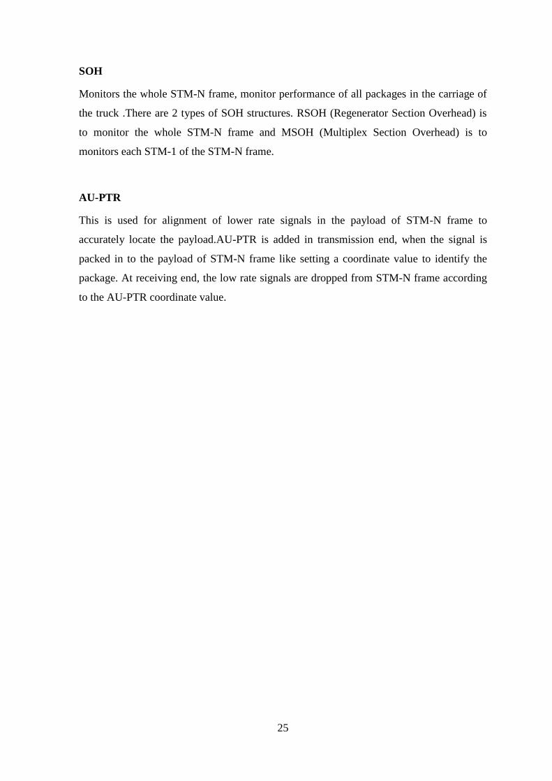
2.5.1 Setting azimuth angle
Figure 2.14-Setting azimuth angle
Normally, there are 3 couples of GSM antenna for a tower. So there 3 sectors can be
identified in the cell. The purpose of this test is to adjust the angle which coverage
maximum number of subscribers.
27
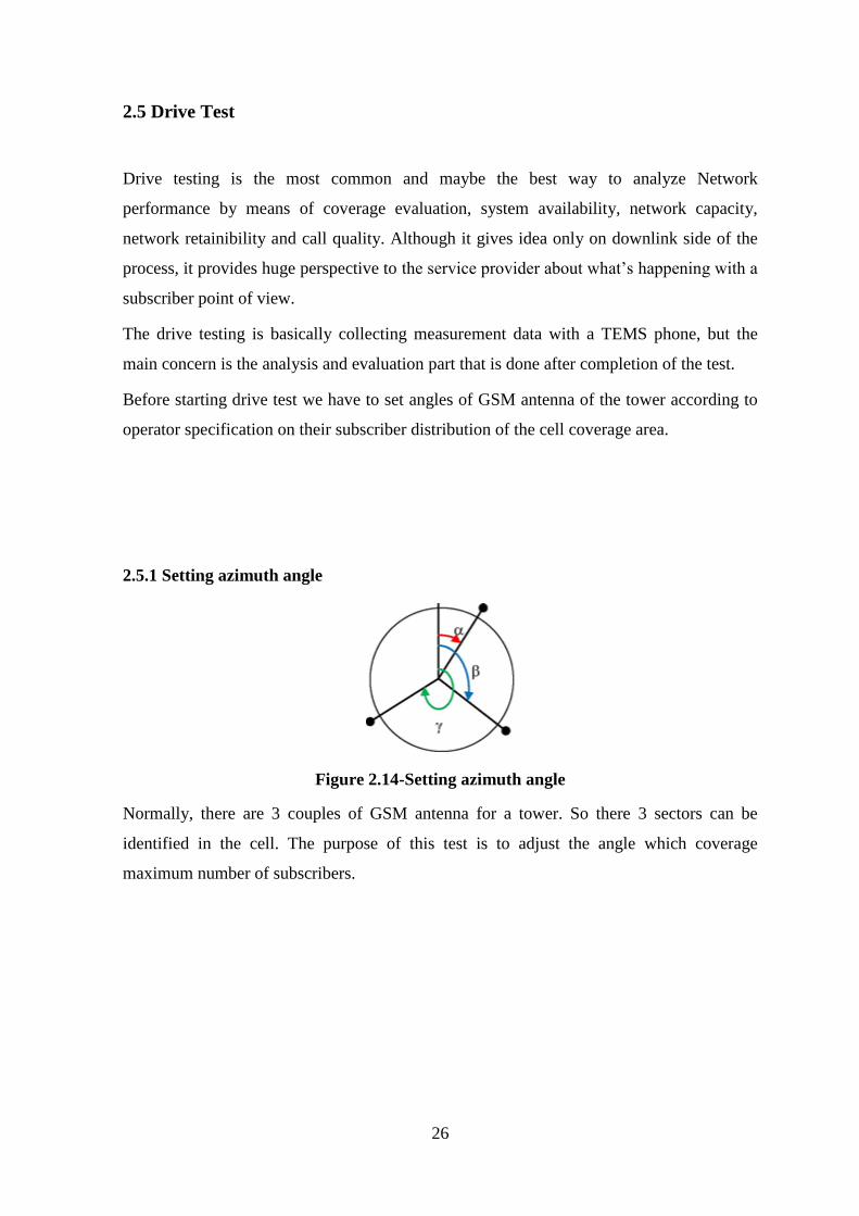
2.5.2 Setting Tilting angle
Figure 2.15-Setting tilting angle
Setting tilting angle means change the vertical angle according to client specification.
2.5.3 Criteria on Drive Test
A drive test system is set up to evaluate statistical call data. Drive test will be terminated at
the point of detection or handover to the second tier neighbor cells. Events should be
included in the drive test plots.
Idle mode drive test should performed by locking to the site’s Primary Scrambling
Code.
Dedicated mode drive test should be performed for both short (Dual mode) and
long (3G only) calls using mobiles.
HSDPA data session drive test should be performed using dongles.
Pre and Post Drive Tests should be performed using the same mobiles and dongles
for both tests.
Phone models / Dongle models / Local server used for throughput testing should be
shared with the Purchaser prior to carrying out the testing.
28
2.5.4 Devices
The test devices must be well prepared before field strength test, and the main devices are
as follows:
Test mobile phone
GPS
External antenna to GPS
Data collection software
Computer/Laptop
Test vehicle
2.5.5 Test Items
Categories Test Item Evaluation Object
Idle Mode RSCP cell
SINR cell
Voice Long Call
RSCP cell
Ec/Io cell
Handover Success Rate cell
Voice Short Call
RSCP/RxLev cell
Ec/Io cell
Call Setup Success Rate cell
Call Drop Rate cell
Data Call Average HSDPA Throughput cell
Average HSUPA Throughput cell
Table 2.6-Test items of Drive test
2.5.6 Drive test Procedure
First we have to enter the location information of the site(Longitude and Latitude) to the
GPS unit. Then these data and cell no. are entered to the application of the Notebook PC.
By using this application (TEMS) an empty digital map is imported to the application
which shows all the geographic representation of the area.
Then the both GPS unit and mobile phone are connected to the PC. By using automatically
generated calls from mobile device we can measure the signal strength of the area from the
display of the PC.
29
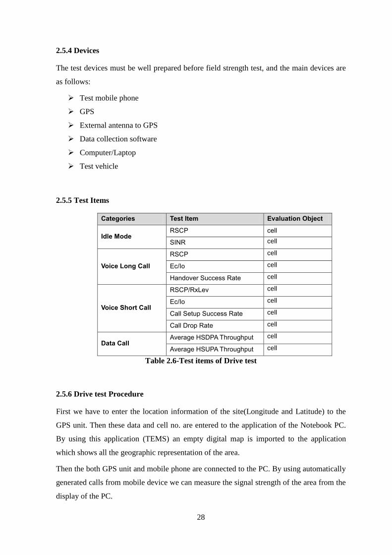
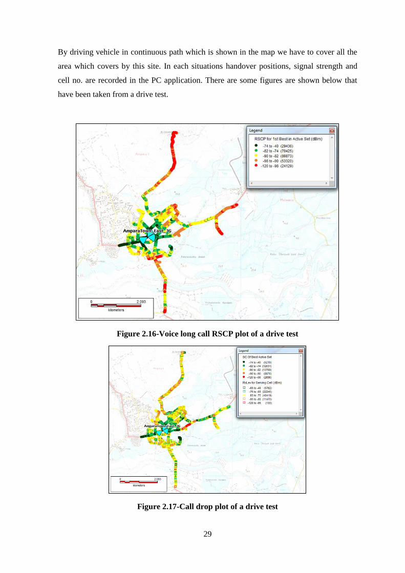
By driving vehicle in continuous path which is shown in the map we have to cover all the
area which covers by this site. In each situations handover positions, signal strength and
cell no. are recorded in the PC application. There are some figures are shown below that
have been taken from a drive test.
Figure 2.16-Voice long call RSCP plot of a drive test
Figure 2.17-Call drop plot of a drive test
30
2.6 VSWR Test
Voltage Standing Wave Ratio (VSWR) is the ratio of the maximum voltage to the
minimum voltage in the standing wave on a transmission line. Standing waves are the
result of reflected RF energy. The most common case for measuring and examining SWR
is when installing and tuning transmitting antennas. When a transmitter is connected to an
antenna by a feed line, the impedance of the antenna and feed line must match exactly for
maximum energy transfer from the feed line to the antenna to be possible. The impedance
of the antenna varies based on many factors including: the antenna's natural resonance at
the frequency being transmitted, the antenna's height above the ground, and the size of the
conductors used to construct the antenna. Radio Frequency (RF) energy losses increase,
distortion on transmitter due to reflected power from load and damage to the transmitter
can occur.
2.6.1 Measuring VSWR
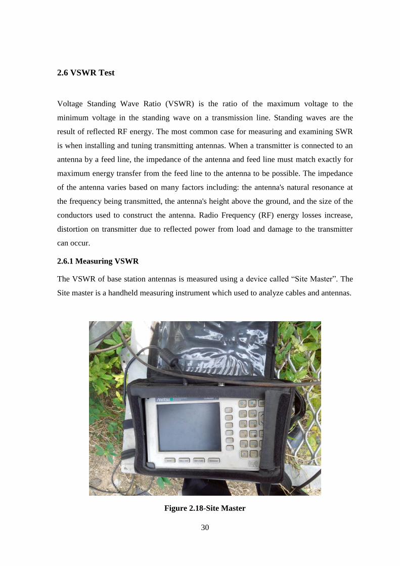
The VSWR of base station antennas is measured using a device called “Site Master”. The
Site master is a handheld measuring instrument which used to analyze cables and antennas.
Figure 2.18-Site Master
31
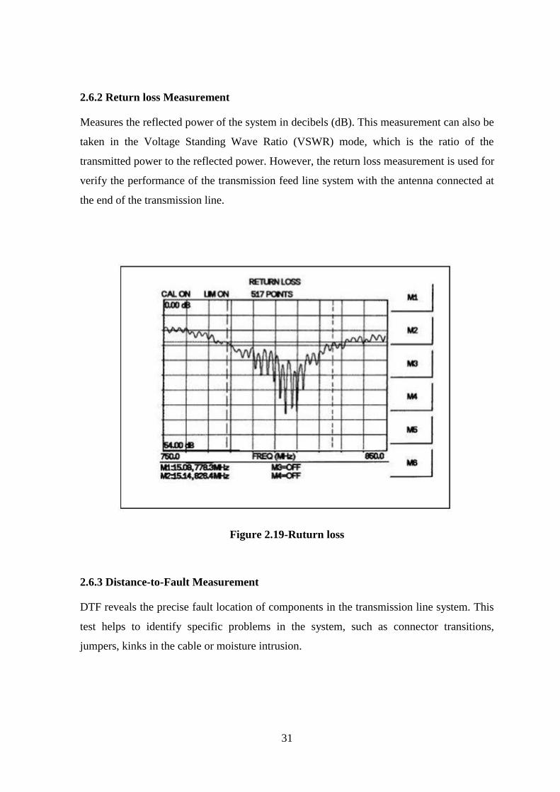
2.6.2 Return loss Measurement
Measures the reflected power of the system in decibels (dB). This measurement can also be
taken in the Voltage Standing Wave Ratio (VSWR) mode, which is the ratio of the
transmitted power to the reflected power. However, the return loss measurement is used for
verify the performance of the transmission feed line system with the antenna connected at
the end of the transmission line.
Figure 2.19-Ruturn loss
2.6.3 Distance-to-Fault Measurement
DTF reveals the precise fault location of components in the transmission line system. This
test helps to identify specific problems in the system, such as connector transitions,
jumpers, kinks in the cable or moisture intrusion.

32
Figure 2.20-DTF measurement
2.6.4 My Experience on using Site Master
In my training period I went to some sites in Thamputhegama and Galgamuwa for
inspection. I measured VSWR, Return loss and DTF using site master in those sites.
33
2.7 Reports on Telecommunication
Even though as a vendor ZTE prepared many reports, both of these are very important.
TSSR
SSV
In my training period mostly I spent time with preparing these reports.
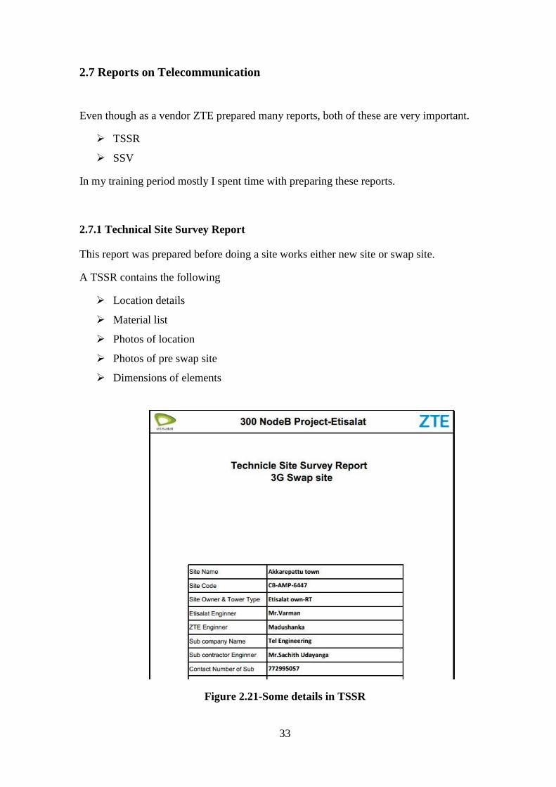
2.7.1 Technical Site Survey Report
This report was prepared before doing a site works either new site or swap site.
A TSSR contains the following
Location details
Material list
Photos of location
Photos of pre swap site
Dimensions of elements
Figure 2.21-Some details in TSSR
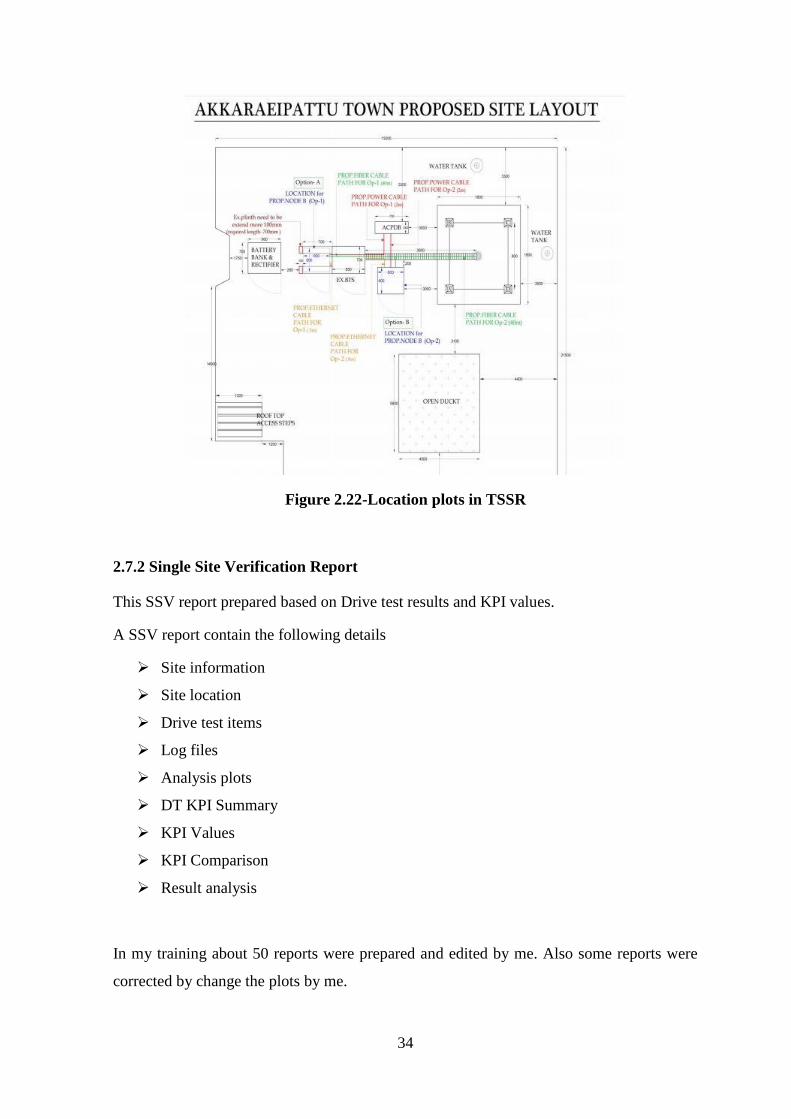
34
Figure 2.22-Location plots in TSSR
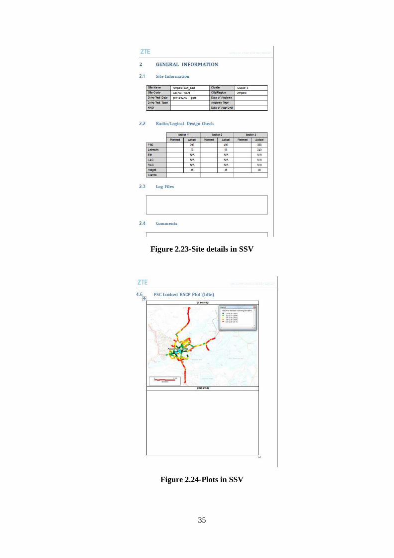
2.7.2 Single Site Verification Report
This SSV report prepared based on Drive test results and KPI values.
A SSV report contain the following details
Site information
Site location
Drive test items
Log files
Analysis plots
DT KPI Summary
KPI Values
KPI Comparison
Result analysis
In my training about 50 reports were prepared and edited by me. Also some reports were
corrected by change the plots by me.
35
Figure 2.23-Site details in SSV
Figure 2.24-Plots in SSV
36
2.8 Key Performance Indicators
KPIs are important criteria used to evaluate the operation of wireless networks.
KPIs reflect the network running status.
I prepared reports based on LTE and 2G KPIs
2.8.1 LTE KPIs
Based on the measurement targets the KPIs are classified as follows.
Accessibility
Retainability
Mobility
Traffic
Availability
Accessibility KPIs
Accessibility KPIs are used to measure the probability whether services requested by a user
can be accessed within specified tolerances in the given operating conditions.
The accessibility KPIs can be calculated per cell or cluster.
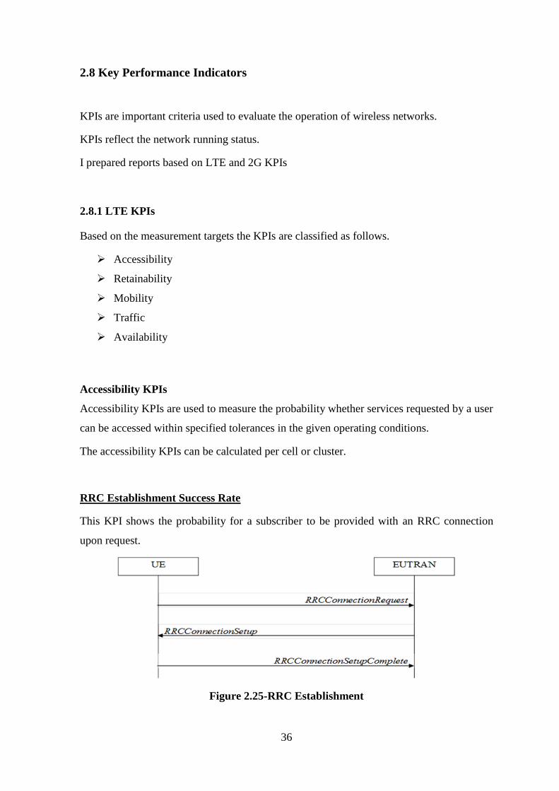
RRC Establishment Success Rate
This KPI shows the probability for a subscriber to be provided with an RRC connection
upon request.
Figure 2.25-RRC Establishment
37
RRC – Radio Resource Control
UE – User Equipment
EUTRAN – Evolved Universal Terrestrial Access Network
E-RAB Setup Success Rate
This KPI shows probability for an end-user to successfully setup an ERAB at request.
E-RAP – Radio Access Bearers
Call Setup Success Rate
This KPI can be used to evaluate the call setup success rate of all services including the
VoIP service in a cell or a cluster.
VoIP – Voice over Internet Protocol
Also some other accessibility KPIs
E-RAB Block Rate
Initial E-RAB Setup Success Rate
Added E-RAB Setup Success Rate
Retainability KPIs
Retainability KPIs are used to evaluate the network capability to retain services requested
by a user for a desired duration once the user is connected to the services.
Retainability KPIs are important in evaluating whether the system can maintain the service
quality at certain level.
38
E-RAB Drop Rate
This KPI shows the probability for a subscriber to loss the E-RAB, such as an event being
released by the eNodeB due to overload control.
VoIP Drop Rate
This KPI can be used to evaluate the call drop rate of the VoIP service in a cell or a cluster.
The call drop rate is calculated by monitoring the VoIP ERAB abnormal release rate.
Mobility KPIs
Mobility KPIs are used to evaluate the performance of E-UTRAN mobility, which is
critical to the customer experience.
Intra-Frequency Handover Success Rate
This KPI can be used to evaluate the intra-frequency Handover success rate in a cell or a
cluster.
The intra-frequency handover includes both inter-eNodeB and intra-eNodeB scenarios.
Inter-Frequency Handover Success Rate
Similar to Intra-frequency Handover Success Rate, the target eNodeB and source eNodeB
are at different frequencies.
This KPI can be used to evaluate the inter-frequency handover out success rate in a cell or
a cluster.
UMTS to LTE Handover Success Rate
LTE to UMTS Handover Success Rate
39
Traffic KPIs
Traffic KPIs are used to measure the traffic volume on the LTE Radio Access Network
(RAN).
Maximum Cell DL PDCP Throughput
Maximum Cell UL PDCP Throughput
Average Cell DL PDCP Throughput
Average Cell UL PDCP Throughput
Average Active State User Number
This KPI evaluate the average number of users which has the RRC connection in the cell.
This value is calculated based on samples, eNodeB will record the user number in the cell
to be a sample every second, and then calculate the average value of these samples in the
measurement period.
Peak Active State User Number
This KPI evaluate the maximum number of users which has the RRC connection in the cell
in a period.
This value is calculated based on samples, eNodeB will record the user number in the cell
to be a sample every second, and then get the maximum value of these samples in the
measurement period.
40
Availability KPIs
Availability is the percentage of time that a cell is available.
A cell is available when the eNodeB can provide EPS bearer services.
Cell Availability
The cell availability measures the ratio of in-service time to measurement granularity time.
The in-service time indicates the time interval between cell establishment and cell deletion.
By counting the cell in-service time, this KPI forms a foundation for analyzing system
failures and measuring system stability.
2.8.2 2GKPIs
SDCCH Congestion Rate
SDCCH - Standalone Dedicated Control Channel
SDCCH is a dedicated channel which is using for LAC updating, Call setup, SMS
in idle mode.
It works in UL & DL.
Congestion ratio on SDCCH is one of the most important accessibility KPIs in the
CS service.
The congestion ratio on SDCCH can be obtained through the traffic measurement
results.
If the congestion ratio on SDCCH is high, MSs cannot access the signaling channel,
and thus the services requested by MSs Fail.
SDCCH Call Drop Rate
SDCCH Call Drop Rate indicates the probability of call drops that occur when MSs
occupy SDCCHs.
41
SDCCH Call Drop Rate is one of accessibility KPIs. This KPI reflects the seizure
condition of signaling channels. If the value of this KPI is high, user experience is
adversely affected.
Environment Factors That Affect SDCCH Call Drop Rate
Coverage - Blind coverage area, low coverage level, or cross coverage,
which cannot be solved through network optimization.
Interference - Unavoidable inter-network interference, interference from
repeaters, or high and unavoidable intra-network interference caused by
aggressive frequency reuse.
Transmission - Poor transmission quality and unstable transmission links
over the Abis interface.
Antenna System - High VSWR due to feeders leads to the reduction in the
transmit power and in the receiver sensitivity. In consequence, the network
has poor coverage and call drops occur.
Device - A large number of unavailable terrestrial resources or faulty
devices.
SDCCH Call Drop Rate is one of traffic measurement KPIs and can be obtained
through traffic measurement. There is a great difference between the drive test data
and the actual SDCCH Call Drop Rate. Therefore, SDCCH Call Drop Rate cannot
be measured through drive tests.
TCH Assignment Success Rate
TCH – Traffic Channel
TCH Assignment Success Rate is one of accessibility KPIs. It indicates the ratio of
successfully seizing TCHs and making calls.
This KPI directly affects user experience.
TCH Assignment Success Rate is obtained through traffic measurement.
TCH Assignment Success Rate refers to the successful seizure ratio of TCHs
assigned by the BSC during the assignment procedure. The TCH assignment
procedure refers to the process between the time the BSC receives the assignment
request message from the MSC and the time the BSC receives the assignment
complete message.
42
Generally, this KPI is not measured through drive tests because of the limited
samples and incomplete test routes.
TCH Call Drop Rate
Call Drop Ratio on TCH indicates the ratio of the number of call drops to the
number of successful TCH seizures after the BSC successfully assigns TCHs to
MSs.
Call Drop Ratio on TCH contains the probability of call drops after the
establishment of TCHs and the probability of call drops during call establishment.
Call Drop Ratio on TCH is one of retainability KPIs.
It reflects the probability of call drops due to various reasons after the MSs Access
the TCHs properly. If Call Drop Ratio on TCH is high, user experience is adversely
affected.
Handover Success Rate
The purpose of handover is to ensure the call continuity, improve the speech
quality, and reduce the cross interference in the network, thus providing better
services for the subscribers.
Success ratio of handover is the ratio of the total number of successful handovers to
the total number of handover requests.
This counter directly affects the user experience and is one of the most significant
KPIs for the telecom operator.
The success rate of handover is an important retainability KPI.
Success Rate of Call Setup
It can be abbreviated as CSSR, which reflects the probability of successful calls
initiated by the MS.
The CSSR is a key counter in evaluating the network performance. If the value of
this counter is low, the MS is not likely to successfully initiate a call, thus severely
affecting the user experience.
43
Call Complete Success Rate
Call Complete Establishment Success Rate is abbreviated as CCSR, which is the
ratio of the number of established calls to the total number of initiated calls.
A complete call procedure starts from the initiation of a call or the response to the
paging to the moment of hang-up.
This counter is an important retainability KPI, which directly indicates the
probability of complete calls. This counter directly affects user experience.
The Call Complete Establishment Success Rate is a comprehensive counter. For its
measurement point, refer to those of the specific counters.
SDCCH Congestion Rate
SDCCH Call Drop Rate
TCH Congestion Rate
TCH Call Drop Rate
Drop Call
All cell resources are available but calls are failing, then we have a call drop
scenario.
This could be caused by software errors, congestion, C7 link failures, HW problems
or many other reasons.
44
CHAPTER 03
3. Training Experience – Management
During my training period at the ZTE Lanka (Pvt) Ltd, I could not able to interact much
with the marketing side. But from some of lectures, I was able to get some idea about the
management procedure of the establishment. Basically the staff can be divided into
categories starting from SGM, Engineers, Technical Officers, Clerical staff and
maintenance employees. And when considering the salary of the employees, the overall
performance is quite good. Staffs of ZTE were rapidly discussed about their ongoing
projects. Then they get decisions for success of ZTE. It should be mentioned that all the
employees including Managers, Engineers, and Technical Officers and normal office staff
treats each other with brotherhood. So in this training period we experienced well in such
friendly background.
3.1 Transport Management
ZTE Lanka (Pvt) Ltd is currently maintaining high volume of Transport service because of
the increasing mobile requirements. There are lots of vehicles (Vans) that the ZTE is using
for carrying tools and equipment with triggermen, and for Drive tests, to do site surveys,
tools like repeater installation and configuration, and even for employee transporting. All
the engineers have dedicated vehicles for their official necessities and even some Technical
officers also. There is a special vehicle coordination unit for arrange the vehicles according
to the requirements. Once we need to go out for some official work, then we can call for
that unit and then they will prepare a free vehicle in a flash. So the overall transportation
facility is good in the division.
45
3.2 Office Practices
As a well-established organization, there are guidelines for the company. The working staff
has to contribute for the development of the company and to increase the revenues of the
company. The company has regular working hours from 9.00 a.m. to 5.30 p.m. For trainees
also they are implementing work schedules.
46
CHAPTER 04
4. Summary and Conclusion
4.1 Summary
I was assigned as a trainee at ZTE Lanka (Pvt) Ltd. During that 03months period I
achieved lot of knowledge and experience relating to the mobile communication
field, inner workings of an Engineering firm, interactions with the officials and more. I
was appointed to the currently ongoing Mobitel Project.
At the ZTE Lanka (Pvt) Ltd I had lot of chances to get hands on experience with the tools,
cables, hardware, etc. Thus the project consisted mostly site visits thus involved lot
of practical works.
This was my first experience as a trainee Engineer as well as this was my first experience
at a professional worksite. At the end of the training I was able to collect lot of experiences
regarding practical Engineering, professionalism and management.
4.2 Conclusion
Industrial training plays a vital role in the overall Engineering undergraduate curriculum in
integrating the skills, the knowledge and the attitudes about the industry of the
undergraduate. I've got a good opportunity to have my first industrial training in ZTE
Lanka (Pvt) Ltd. As an engineering student of University of Ruhuna, I took a lot of
practical knowledge about telecommunication area and its technologies when I was in the
ZTE Lanka (Pvt) Ltd. During this valuable period I was able to take so much experiences
and mobile telecommunication equipment that is used currently in the world and also was
able to have hands on experience on installation and troubleshooting of much
telecommunication equipment.
The reason for chosen ZTE as my first training place, as I interested in telecommunication
subject area very much and this training establishment which I chosen is capable of
providing training practically on any area related to telecommunication.
47
I feel discontented about the amount of technological knowledge gained in this 12 weeks
period. We could have created more opportunities ourselves and most importantly more
opportunities had to be created by the organization.
I got the more experience how to work and deal with company staff, sub-contractors. I'm
pleased with the training experiences Here I should mention that I was able to get an
opportunity to work with mechanics, technical officers, engineers and share their
knowledge and experiences. Those things gave me a really good training as an engineering
undergraduate.
Finally I would like to mention that the three month in training experience given to us as a
result of the dedication and commitment of a large group of people and it has been a rather
successful one which provided basic foundation for an Engineering undergraduate to
launch into the industry and start a successful carrier.

48
References
Official website of ZTE Corporation, www.zte.com.cn
ZTE University presentations / Coursework Material of ZTE for trainees.
www.google.com/search.html
www.wikipedia.org / Wikipedia the free encyclopedia.html
49
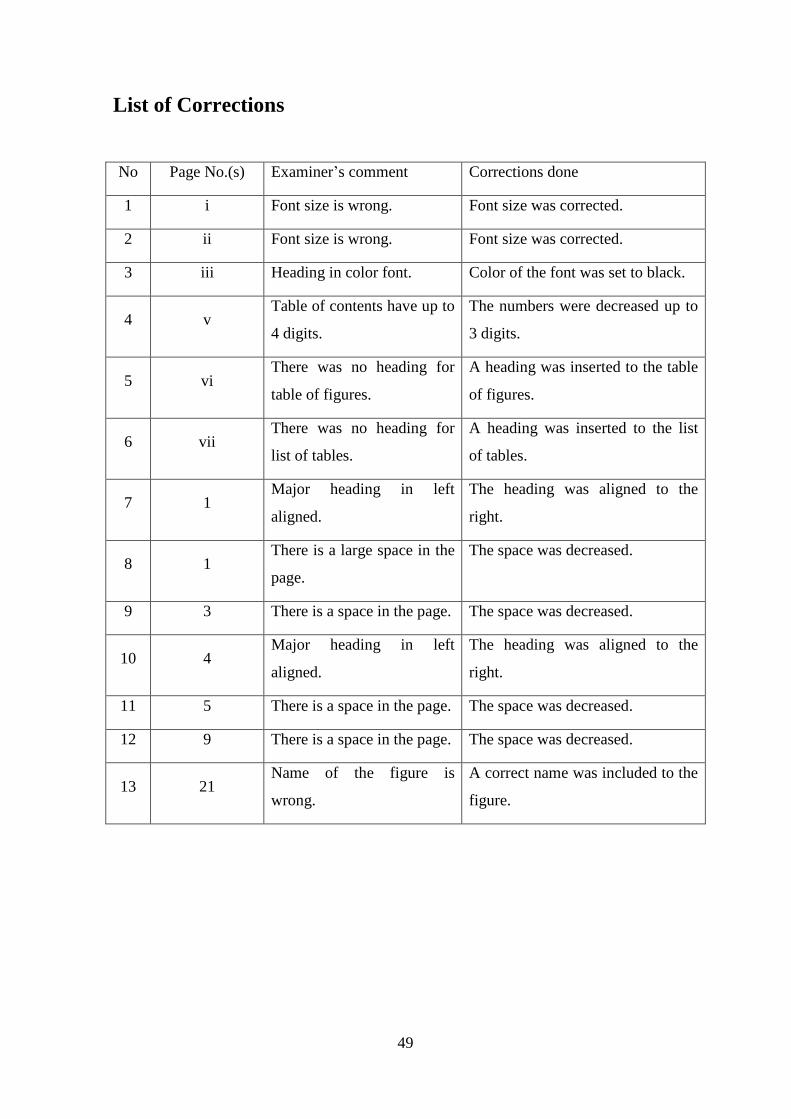
List of Corrections
No Page No.(s) Examiner’s comment Corrections done
1 i Font size is wrong. Font size was corrected.
2 ii Font size is wrong. Font size was corrected.
3 iii Heading in color font. Color of the font was set to black.
4 v Table of contents have up to
4 digits.
The numbers were decreased up to
3 digits.
5 vi There was no heading for
table of figures.
A heading was inserted to the table
of figures.
6 vii There was no heading for
list of tables.
A heading was inserted to the list
of tables.
7 1 Major heading in left
aligned.
The heading was aligned to the
right.
8 1 There is a large space in the
page.
The space was decreased.
9 3 There is a space in the page. The space was decreased.
10 4 Major heading in left
aligned.
The heading was aligned to the
right.
11 5 There is a space in the page. The space was decreased.
12 9 There is a space in the page. The space was decreased.
13 21 Name of the figure is
wrong.
A correct name was included to the
figure.
Related Documents